KR20130129059A - A cleaner comprising rag portion without an electricity - Google Patents
A cleaner comprising rag portion without an electricity Download PDFInfo
- Publication number
- KR20130129059A KR20130129059A KR1020120110271A KR20120110271A KR20130129059A KR 20130129059 A KR20130129059 A KR 20130129059A KR 1020120110271 A KR1020120110271 A KR 1020120110271A KR 20120110271 A KR20120110271 A KR 20120110271A KR 20130129059 A KR20130129059 A KR 20130129059A
- Authority
- KR
- South Korea
- Prior art keywords
- lamp
- cleaner
- mop
- unit
- sterilizing water
- Prior art date
Links
- 230000005611 electricity Effects 0.000 title claims description 8
- XLYOFNOQVPJJNP-UHFFFAOYSA-N water Substances O XLYOFNOQVPJJNP-UHFFFAOYSA-N 0.000 claims abstract description 106
- 230000001954 sterilising effect Effects 0.000 claims abstract description 98
- 238000005507 spraying Methods 0.000 claims abstract description 26
- 239000000460 chlorine Substances 0.000 claims abstract description 21
- 238000000034 method Methods 0.000 claims abstract description 11
- ZAMOUSCENKQFHK-UHFFFAOYSA-N Chlorine atom Chemical compound [Cl] ZAMOUSCENKQFHK-UHFFFAOYSA-N 0.000 claims abstract description 10
- 229910052801 chlorine Inorganic materials 0.000 claims abstract description 10
- 239000003595 mist Substances 0.000 claims abstract description 4
- QWPPOHNGKGFGJK-UHFFFAOYSA-N hypochlorous acid Chemical group ClO QWPPOHNGKGFGJK-UHFFFAOYSA-N 0.000 claims description 16
- 238000002347 injection Methods 0.000 claims description 16
- 239000007924 injection Substances 0.000 claims description 16
- BASFCYQUMIYNBI-UHFFFAOYSA-N platinum Chemical group [Pt] BASFCYQUMIYNBI-UHFFFAOYSA-N 0.000 claims description 9
- 239000007921 spray Substances 0.000 claims description 7
- 238000004140 cleaning Methods 0.000 claims description 4
- 239000007769 metal material Substances 0.000 claims description 4
- WQYVRQLZKVEZGA-UHFFFAOYSA-N hypochlorite Chemical compound Cl[O-] WQYVRQLZKVEZGA-UHFFFAOYSA-N 0.000 claims description 3
- 150000003254 radicals Chemical class 0.000 claims description 3
- 239000000203 mixture Substances 0.000 claims description 2
- 239000007800 oxidant agent Substances 0.000 claims description 2
- 230000001590 oxidative effect Effects 0.000 claims description 2
- 239000003054 catalyst Substances 0.000 claims 1
- 238000004659 sterilization and disinfection Methods 0.000 abstract description 33
- 239000003792 electrolyte Substances 0.000 abstract description 9
- 238000005868 electrolysis reaction Methods 0.000 abstract description 7
- KZBUYRJDOAKODT-UHFFFAOYSA-N Chlorine Chemical compound ClCl KZBUYRJDOAKODT-UHFFFAOYSA-N 0.000 abstract description 3
- 230000000694 effects Effects 0.000 abstract description 2
- 230000015572 biosynthetic process Effects 0.000 abstract 1
- FAPWRFPIFSIZLT-UHFFFAOYSA-M Sodium chloride Chemical compound [Na+].[Cl-] FAPWRFPIFSIZLT-UHFFFAOYSA-M 0.000 description 10
- 239000011780 sodium chloride Substances 0.000 description 5
- VEXZGXHMUGYJMC-UHFFFAOYSA-M Chloride anion Chemical compound [Cl-] VEXZGXHMUGYJMC-UHFFFAOYSA-M 0.000 description 4
- 239000000428 dust Substances 0.000 description 4
- KDLHZDBZIXYQEI-UHFFFAOYSA-N Palladium Chemical compound [Pd] KDLHZDBZIXYQEI-UHFFFAOYSA-N 0.000 description 3
- 230000007935 neutral effect Effects 0.000 description 3
- 239000000126 substance Substances 0.000 description 3
- 230000003197 catalytic effect Effects 0.000 description 2
- 230000003247 decreasing effect Effects 0.000 description 2
- 239000010948 rhodium Substances 0.000 description 2
- 241000894006 Bacteria Species 0.000 description 1
- RYGMFSIKBFXOCR-UHFFFAOYSA-N Copper Chemical compound [Cu] RYGMFSIKBFXOCR-UHFFFAOYSA-N 0.000 description 1
- 241000588724 Escherichia coli Species 0.000 description 1
- KJTLSVCANCCWHF-UHFFFAOYSA-N Ruthenium Chemical compound [Ru] KJTLSVCANCCWHF-UHFFFAOYSA-N 0.000 description 1
- 230000002378 acidificating effect Effects 0.000 description 1
- 238000006243 chemical reaction Methods 0.000 description 1
- 150000001805 chlorine compounds Chemical class 0.000 description 1
- 239000004020 conductor Substances 0.000 description 1
- 229910052802 copper Inorganic materials 0.000 description 1
- 239000010949 copper Substances 0.000 description 1
- 238000004090 dissolution Methods 0.000 description 1
- 239000003814 drug Substances 0.000 description 1
- 229940079593 drug Drugs 0.000 description 1
- 150000002500 ions Chemical class 0.000 description 1
- 239000000463 material Substances 0.000 description 1
- 238000012986 modification Methods 0.000 description 1
- 230000004048 modification Effects 0.000 description 1
- 229910052763 palladium Inorganic materials 0.000 description 1
- 230000000737 periodic effect Effects 0.000 description 1
- 229910052697 platinum Inorganic materials 0.000 description 1
- 238000003825 pressing Methods 0.000 description 1
- 229910052703 rhodium Inorganic materials 0.000 description 1
- MHOVAHRLVXNVSD-UHFFFAOYSA-N rhodium atom Chemical compound [Rh] MHOVAHRLVXNVSD-UHFFFAOYSA-N 0.000 description 1
- 229910052707 ruthenium Inorganic materials 0.000 description 1
- 229910001925 ruthenium oxide Inorganic materials 0.000 description 1
- WOCIAKWEIIZHES-UHFFFAOYSA-N ruthenium(iv) oxide Chemical compound O=[Ru]=O WOCIAKWEIIZHES-UHFFFAOYSA-N 0.000 description 1
- 239000008223 sterile water Substances 0.000 description 1
- 239000003206 sterilizing agent Substances 0.000 description 1
- 238000003756 stirring Methods 0.000 description 1
- 238000005406 washing Methods 0.000 description 1
Images


Classifications
-
- A—HUMAN NECESSITIES
- A47—FURNITURE; DOMESTIC ARTICLES OR APPLIANCES; COFFEE MILLS; SPICE MILLS; SUCTION CLEANERS IN GENERAL
- A47L—DOMESTIC WASHING OR CLEANING; SUCTION CLEANERS IN GENERAL
- A47L11/00—Machines for cleaning floors, carpets, furniture, walls, or wall coverings
- A47L11/26—Floor-scrubbing machines, hand-driven
-
- A—HUMAN NECESSITIES
- A47—FURNITURE; DOMESTIC ARTICLES OR APPLIANCES; COFFEE MILLS; SPICE MILLS; SUCTION CLEANERS IN GENERAL
- A47L—DOMESTIC WASHING OR CLEANING; SUCTION CLEANERS IN GENERAL
- A47L11/00—Machines for cleaning floors, carpets, furniture, walls, or wall coverings
- A47L11/40—Parts or details of machines not provided for in groups A47L11/02 - A47L11/38, or not restricted to one of these groups, e.g. handles, arrangements of switches, skirts, buffers, levers
- A47L11/4036—Parts or details of the surface treating tools
- A47L11/4038—Disk shaped surface treating tools
-
- A—HUMAN NECESSITIES
- A47—FURNITURE; DOMESTIC ARTICLES OR APPLIANCES; COFFEE MILLS; SPICE MILLS; SUCTION CLEANERS IN GENERAL
- A47L—DOMESTIC WASHING OR CLEANING; SUCTION CLEANERS IN GENERAL
- A47L11/00—Machines for cleaning floors, carpets, furniture, walls, or wall coverings
- A47L11/40—Parts or details of machines not provided for in groups A47L11/02 - A47L11/38, or not restricted to one of these groups, e.g. handles, arrangements of switches, skirts, buffers, levers
- A47L11/4036—Parts or details of the surface treating tools
- A47L11/405—Machines using UV-lamps, IR-lamps, ultrasound or plasma cleaning
-
- A—HUMAN NECESSITIES
- A47—FURNITURE; DOMESTIC ARTICLES OR APPLIANCES; COFFEE MILLS; SPICE MILLS; SUCTION CLEANERS IN GENERAL
- A47L—DOMESTIC WASHING OR CLEANING; SUCTION CLEANERS IN GENERAL
- A47L11/00—Machines for cleaning floors, carpets, furniture, walls, or wall coverings
- A47L11/40—Parts or details of machines not provided for in groups A47L11/02 - A47L11/38, or not restricted to one of these groups, e.g. handles, arrangements of switches, skirts, buffers, levers
- A47L11/408—Means for supplying cleaning or surface treating agents
- A47L11/4083—Liquid supply reservoirs; Preparation of the agents, e.g. mixing devices
-
- A—HUMAN NECESSITIES
- A47—FURNITURE; DOMESTIC ARTICLES OR APPLIANCES; COFFEE MILLS; SPICE MILLS; SUCTION CLEANERS IN GENERAL
- A47L—DOMESTIC WASHING OR CLEANING; SUCTION CLEANERS IN GENERAL
- A47L11/00—Machines for cleaning floors, carpets, furniture, walls, or wall coverings
- A47L11/40—Parts or details of machines not provided for in groups A47L11/02 - A47L11/38, or not restricted to one of these groups, e.g. handles, arrangements of switches, skirts, buffers, levers
- A47L11/408—Means for supplying cleaning or surface treating agents
- A47L11/4088—Supply pumps; Spraying devices; Supply conduits
-
- A—HUMAN NECESSITIES
- A47—FURNITURE; DOMESTIC ARTICLES OR APPLIANCES; COFFEE MILLS; SPICE MILLS; SUCTION CLEANERS IN GENERAL
- A47L—DOMESTIC WASHING OR CLEANING; SUCTION CLEANERS IN GENERAL
- A47L11/00—Machines for cleaning floors, carpets, furniture, walls, or wall coverings
- A47L11/40—Parts or details of machines not provided for in groups A47L11/02 - A47L11/38, or not restricted to one of these groups, e.g. handles, arrangements of switches, skirts, buffers, levers
- A47L11/4094—Accessories to be used in combination with conventional vacuum-cleaning devices
-
- A—HUMAN NECESSITIES
- A61—MEDICAL OR VETERINARY SCIENCE; HYGIENE
- A61L—METHODS OR APPARATUS FOR STERILISING MATERIALS OR OBJECTS IN GENERAL; DISINFECTION, STERILISATION OR DEODORISATION OF AIR; CHEMICAL ASPECTS OF BANDAGES, DRESSINGS, ABSORBENT PADS OR SURGICAL ARTICLES; MATERIALS FOR BANDAGES, DRESSINGS, ABSORBENT PADS OR SURGICAL ARTICLES
- A61L2/00—Methods or apparatus for disinfecting or sterilising materials or objects other than foodstuffs or contact lenses; Accessories therefor
- A61L2/02—Methods or apparatus for disinfecting or sterilising materials or objects other than foodstuffs or contact lenses; Accessories therefor using physical phenomena
- A61L2/08—Radiation
- A61L2/10—Ultraviolet radiation
Landscapes
- Physics & Mathematics (AREA)
- Engineering & Computer Science (AREA)
- Plasma & Fusion (AREA)
- Apparatus For Disinfection Or Sterilisation (AREA)
- Health & Medical Sciences (AREA)
- Epidemiology (AREA)
- Life Sciences & Earth Sciences (AREA)
- Animal Behavior & Ethology (AREA)
- General Health & Medical Sciences (AREA)
- Public Health (AREA)
- Veterinary Medicine (AREA)
- Water Treatment By Electricity Or Magnetism (AREA)
Abstract
Description
The present invention relates to a vacuum cleaner, and more particularly, to apply electric power to raw water that does not add a separate electrolyte to prepare and spray sterilized water including a mixed oxide (MO), and a cleaner including a mop part in which a mop part can be rotated without power. It is about.
Conventional vacuum cleaners are generally devices for sucking dust and foreign matter, but recently, various cleaners having a disinfection function using ultraviolet rays or steam have appeared.
However, the vacuum cleaners having the disinfection function have a sterilizing effect, and thus do not play a role of more than a conventional vacuum cleaner. In order to solve this problem, a "cleaner having a mop function (Korean Patent Publication No. 10-2006-0032058) (hereinafter referred to as" a conventional electrolytic sterilizing water cleaner ") that provides sterilizing water using electrolysis is used. Started.
A conventional electrolytic sterilizing water cleaner will be described with reference to FIG. 1. In the conventional electrolytic sterilizing water cleaner, a separate electrolyte sodium chloride (NaCl), which is a kind of chloride, is introduced into the
The positive electrode plate and the negative electrode plate are made of copper, which is a conductor, and sterilization water is generated by applying electricity to the positive electrode plate and the negative electrode plate. Strong acidic water is produced in the anode chamber, and strong alkaline water is produced in the cathode chamber and used as sterilizing water.
Hereinafter, the sterilizing power of the sterilizing water generated by the conventional electrolytic sterilizing water cleaner will be described in detail.
residual chlorine according to the pH change is present in the neutral form but most HOCl, if the pH increases, the OCl-is present in the form-and to increase the (alkaline), most OCl not less than a pH of 8. On the contrary, when the pH is decreased, the amount of Cl 2 is increased. When the pH is 2 or less, the amount of Cl 2 is rapidly increased and the amount of HOCl is decreased.
At this time, the order of the sterilizing effect is HOCl, OCl -, and the order of, NH Cl 2, HOCl is OCl - will have a sterilization capacity of about 300 times of 70 times, the NH 2 Cl. Thus, it can be seen that HOCl is most advantageous when the same amount of residual chlorine is present.
However, in the sterilizing water of the conventional electrolytic sterilizing water cleaner which dissolves NaCl in water to form residual chlorine, the amount of HOCl is significantly reduced, and most of it exists in the form of OCl − (cathode chamber) or Cl 2 (anode chamber).
In this case, since the strength of the sterilizing power is about 1/70 of the HOCl, the sterilizing water having a capacity of about 70 times larger than that of the HOCl is required.
In the case of using the sterilized drug has a Cl dissolved in water - instead of using, the Cl is supplied from NaCl - because of using a plurality beyond the solubility of the Cl-the-so discharged to the outside of the water a Cl supplied from NaCl Not all can be used, due to this there is a problem that chlorine gas occurs.
In addition, the conventional electrolytic sterilization water cleaners require a user to periodically input a separate electrolyte and require a chloride supply device. Since the sterilization apparatus requiring the chloride supply device has to wait until the chloride is completely dissolved, it takes a long time, and there is a problem that an additional structure such as a stirring device is required to reduce the dissolution time.
In addition, the conventional electrolytic sterilizing water cleaner supplies the generated sterilizing water to the mop 2 through the supply pipe to clean the surface to be cleaned. This results in indirectly spraying sterilized water on the surface to be cleaned, and the sterilization of the surface to be cleaned is insufficient, and a large amount of the sterilized water is only absorbed by the mop and is not used for sterilization.
(Patent Document 1) KR10-2006-0032058 A
An object of the present invention for solving the conventional problems as described above is to provide a cleaner including a mop portion that can be rotated by the mop part at the same time without mist spraying to have a high sterilization effect.
According to an embodiment of the present invention, a cleaner including an intake port and a mop operation unit through which air is sucked, wherein the mop operation unit comprises: a mop unit; A wing portion rotated by the air sucked through the suction port; And a worm gear that rotates by the rotation of the wing portion, wherein the mop portion rotates by the rotation of the worm gear.
Preferably, the cleaner, sterilizing water generation unit including an electrode coated with a catalytic means to generate the sterilized water containing mixed oxide (Mixed Oxidant, MO) by applying electricity to the raw water introduced; And a spraying unit connected to the sterilizing water generating unit and spraying the sterilizing water generated by the sterilizing water generating unit onto the surface to be cleaned, wherein the mop part cleans the surface to be sprayed with the sterilizing water sprayed. .
Preferably, the spraying unit is characterized in that the mist spraying the sterilizing water.
Preferably, the electrode is characterized by being coated with a platinum group metal material.
Preferably, the mixture is hypochlorous acid (HOCl), hypochlorite ion (OCl -) is characterized in that it comprises, at least one of chlorine (Cl 2) and a free radical.
Preferably, the sterilizing water generated in the sterilizing water generating unit is stored, characterized in that it further comprises a removable storage.
Preferably, further comprising a pump connected to the injection unit, characterized in that the pump can adjust the injection range of the sterilizing water injected through the injection unit.
Preferably, it further comprises a UV lamp disposed on the bottom of the cleaner.
Preferably, the UV lamp, the suction port, the injection unit, and the mop are sequentially positioned on the bottom surface of the cleaner according to the forward direction of movement of the cleaner, so that the surface to be cleaned sequentially moves as the cleaner moves. Sterilized by a lamp, air is sucked by the inlet, sterilized water is sprayed by the spraying unit and wiped by the mop unit.
Preferably, the apparatus further comprises a UV lamp unit including the UV lamp, wherein the UV lamp unit includes: a reflection unit surrounding the UV lamp outside the UV lamp and reflecting and diffusing light generated by the UV lamp; And a UV lamp switch for applying power to the UV lamp.
According to an embodiment of the present invention, it is possible to generate sterilized water using electrolysis without adding an electrolyte to raw water. The generated sterilizing water is neutral, and the residual chlorine is mostly present in the form of HOCl, which has excellent sterilizing power.
In addition, since the user does not need to add a separate electrolyte, the user's convenience is increased, and a phenomenon in which undissolved chlorine is generated as chlorine gas is prevented.
In addition, the sterilization power is maximized by spraying the generated sterilization water directly on the surface to be cleaned.
In addition, by using the force of the air flowing through the inlet port by rotating the mop without a separate power member it is possible to reduce the power consumption and efficient cleaning.
In addition, UV lamps enable more effective sterilization of various bacteria.
In addition, the spraying range of the sterilized water to be sprayed can be changed according to the use environment.
In addition, the mop can be rotated without a separate power supply.
1 is a perspective view of a cleaner according to the prior art,
2 is an exploded perspective view of a cleaner inlet assembly according to an embodiment of the present disclosure;
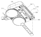
3 is a bottom perspective view of a cleaner suction assembly according to an exemplary embodiment of the present invention.
"EW" used below is an abbreviation of Electrolyzed Water and is defined as sterilized water including mixed oxides produced by electrolyzing raw water without adding sterilizing agents or chlorides.
One. Mop Description of the components of the cleaner containing
2 and 3 will be described the main components of the cleaner including a mop according to an embodiment of the present invention.
The cleaner including a mop according to an embodiment of the present invention includes an
The EW
The sterilizing
Electrolysis occurs as electricity by an external power source is applied to the coated electrode of the sterilizing
One or more
The
In addition, the
In addition, one or
The
In addition, the
The
In addition, the
The
The
Mop 210 may be any operation for cleaning the sterilization water, according to an embodiment of the present invention can be wiped through the rotation of the sterilization water.
The
The worm-
The
The
The
Dust and foreign matter are sucked into the cleaner by using the suction force of the cleaner in the
2. Mop Description of the operation of the cleaner to include
Hereinafter, an operation of the cleaner including the mop will be described with reference to FIGS. 2 to 3 to which an embodiment according to the present invention is attached.
First, when raw water is input, electricity is applied to generate sterilized water including a sterilizing substance at an electrode of the sterilized

The sterilizing water containing the mixed oxide as described above is generated in the sterilizing
Separately, the
In addition, the
The processes described herein can occur simultaneously or sequentially, thus reducing the cleaning time of the user and enabling the sterilization of the surface to be cleaned.
It will be apparent to those skilled in the art that various modifications and variations can be made in the present invention without departing from the spirit or scope of the invention. Therefore, the technical scope of the present invention should not be limited to the contents described in the detailed description of the specification, but should be defined by the claims.
100: EW sterilization unit
110: sterilization water generator
130: injection unit
150:
170: pump
200: mop operation unit
210: mop
230: wing portion
250: Worm Gear
270: PBA Assembly
290: solenoid valve
300: lamp unit
310: UV Lamp
330: reflector
350: UV Lamp Switch
400: inlet
Claims (10)
The mop operation unit,
Mop;
A wing portion rotated by the air sucked through the suction port; And
It further comprises a worm gear that rotates by the rotation of the wing,
The mop portion is characterized in that for rotating by the rotation of the worm gear,
vacuum cleaner.
The cleaner,
A sterilizing water generating unit including an electrode coated with a catalyst means to apply sterilized water containing mixed oxides (Mixed Oxidant, MO) by applying electricity to the introduced raw water; And
And a spraying unit connected to the sterilizing water generating unit and spraying the sterilizing water generated by the sterilizing water generating unit to the surface to be cleaned,
The mop portion is characterized in that for cleaning the surface to be sprayed with the sterilized water,
vacuum cleaner.
The spraying unit is characterized in that the mist spraying the sterilizing water,
vacuum cleaner.
The electrode is coated with a platinum group metal material,
vacuum cleaner.
The mixture is hypochlorous acid (HOCl), hypochlorite ion (OCl -), it characterized in that it comprises, at least one of chlorine (Cl 2) and a free radical,
vacuum cleaner.
The sterilized water generated by the sterilizing water generating unit is stored, characterized in that it further comprises a removable storage,
vacuum cleaner.
Further comprising a pump connected to the injection portion,
The pump can adjust the spraying range of the sterilizing water sprayed through the spraying,
vacuum cleaner.
Further comprising a UV lamp disposed on the bottom of the cleaner,
vacuum cleaner.
The UV lamp, the suction port, the spraying portion, and the mop are sequentially positioned on the bottom of the cleaner according to the moving forward direction of the cleaner,
As the cleaner moves, the surface to be cleaned is sequentially sterilized by the UV lamp, the air is sucked by the suction port, and the sterilizing water is sprayed by the spray unit and wiped by the mop unit.
vacuum cleaner.
Further comprising a UV lamp unit including the UV lamp,
The UV lamp unit,
A reflector which surrounds the UV lamp outside the UV lamp and reflects and diffuses the light generated by the UV lamp; And
UV lamp switch for applying power to the UV lamp
Lt; RTI ID = 0.0 > 1, < / RTI &
vacuum cleaner.
Applications Claiming Priority (2)
| Application Number | Priority Date | Filing Date | Title |
|---|---|---|---|
| KR20120052579 | 2012-05-17 | ||
| KR1020120052579 | 2012-05-17 |
Publications (1)
| Publication Number | Publication Date |
|---|---|
| KR20130129059A true KR20130129059A (en) | 2013-11-27 |
Family
ID=49856010
Family Applications (2)
| Application Number | Title | Priority Date | Filing Date |
|---|---|---|---|
| KR1020120110271A KR20130129059A (en) | 2012-05-17 | 2012-10-04 | A cleaner comprising rag portion without an electricity |
| KR1020120110272A KR20130129060A (en) | 2012-05-17 | 2012-10-04 | A cleaner comprising transducer for mist spray |
Family Applications After (1)
| Application Number | Title | Priority Date | Filing Date |
|---|---|---|---|
| KR1020120110272A KR20130129060A (en) | 2012-05-17 | 2012-10-04 | A cleaner comprising transducer for mist spray |
Country Status (1)
| Country | Link |
|---|---|
| KR (2) | KR20130129059A (en) |
Cited By (13)
| Publication number | Priority date | Publication date | Assignee | Title |
|---|---|---|---|---|
| KR101655684B1 (en) * | 2015-06-15 | 2016-09-07 | 김인기 | Cleaner |
| KR102027386B1 (en) * | 2019-01-30 | 2019-10-02 | 주식회사 브랜뉴인터내셔널 | Wireless wet-cloth vacuum cleaner easy to assemble |
| KR20200013534A (en) * | 2018-07-30 | 2020-02-07 | 엘지전자 주식회사 | Nozzle for cleaner |
| KR20200063259A (en) * | 2016-07-14 | 2020-06-04 | 엘지전자 주식회사 | Cleaner |
| KR20210017586A (en) * | 2019-08-09 | 2021-02-17 | 박남숙 | A pad for attaching cleaning paper and dual rotary steam water mop cleaner |
| KR20210055572A (en) * | 2019-11-06 | 2021-05-17 | 주식회사 미로 | Cleaner head device and cleaner including the same |
| US11058278B2 (en) | 2018-04-30 | 2021-07-13 | Lg Electronics Inc. | Nozzle for cleaner |
| US11096536B2 (en) | 2018-04-30 | 2021-08-24 | Lg Electronics Inc. | Nozzle for cleaner |
| KR102312759B1 (en) * | 2020-05-06 | 2021-10-15 | 주식회사 미로 | Cleaner head device and cleaner including the same |
| US11154172B2 (en) | 2018-04-30 | 2021-10-26 | Lg Electronics Inc. | Nozzle for cleaner |
| US11191415B2 (en) | 2018-04-30 | 2021-12-07 | Lg Electronics Inc. | Nozzle for cleaner |
| WO2022181872A1 (en) * | 2020-10-23 | 2022-09-01 | 주식회사 쓰리엠탑 | Three-mop robot cleaning device having disinfectant module |
| US11786093B2 (en) | 2018-04-30 | 2023-10-17 | Lg Electronics Inc. | Nozzle for cleaner |
Families Citing this family (4)
| Publication number | Priority date | Publication date | Assignee | Title |
|---|---|---|---|---|
| KR101664686B1 (en) * | 2015-04-30 | 2016-10-11 | 엘지전자 주식회사 | Clearner |
| KR101634905B1 (en) * | 2015-06-22 | 2016-06-29 | 엘지전자 주식회사 | Cleaner and water cleaning devce |
| KR101671116B1 (en) | 2015-07-09 | 2016-10-31 | 엘지전자 주식회사 | Cleaner and water cleaning devce |
| KR101769232B1 (en) | 2016-01-14 | 2017-08-17 | 엘지전자 주식회사 | Cleaner and water cleaning devce |
-
2012
- 2012-10-04 KR KR1020120110271A patent/KR20130129059A/en not_active Application Discontinuation
- 2012-10-04 KR KR1020120110272A patent/KR20130129060A/en not_active Application Discontinuation
Cited By (42)
| Publication number | Priority date | Publication date | Assignee | Title |
|---|---|---|---|---|
| KR101655684B1 (en) * | 2015-06-15 | 2016-09-07 | 김인기 | Cleaner |
| US11253126B2 (en) | 2016-07-14 | 2022-02-22 | Lg Electronics Inc. | Robot cleaner |
| US11141034B2 (en) | 2016-07-14 | 2021-10-12 | Lg Electronics Inc. | Cleaner |
| US12075955B2 (en) | 2016-07-14 | 2024-09-03 | Lg Electronics Inc. | Cleaner washing apparatus |
| US11930973B2 (en) | 2016-07-14 | 2024-03-19 | Lg Electronics Inc. | Cleaner |
| US11864697B2 (en) | 2016-07-14 | 2024-01-09 | Lg Electronics Inc. | Robot cleaner and method of controlling the same |
| US11564546B2 (en) | 2016-07-14 | 2023-01-31 | Lg Electronics Inc. | Cleaner |
| US10993598B2 (en) | 2016-07-14 | 2021-05-04 | Lg Electronics Inc. | Robot cleaner and method of controlling the same |
| KR20200063259A (en) * | 2016-07-14 | 2020-06-04 | 엘지전자 주식회사 | Cleaner |
| US11019975B2 (en) | 2016-07-14 | 2021-06-01 | Lg Electronics Inc. | Robot cleaner |
| US11051671B2 (en) | 2016-07-14 | 2021-07-06 | Lg Electronics Inc. | Cleaner |
| US11202547B2 (en) | 2016-07-14 | 2021-12-21 | Lg Electronics Inc. | Cleaner |
| US11071429B2 (en) | 2016-07-14 | 2021-07-27 | Lg Electronics Inc. | Robot cleaner |
| US11937752B2 (en) | 2018-04-30 | 2024-03-26 | Lg Electronics Inc. | Nozzle for cleaner |
| US11957296B2 (en) | 2018-04-30 | 2024-04-16 | Lg Electronics Inc. | Nozzle for cleaner |
| US12082756B2 (en) | 2018-04-30 | 2024-09-10 | Lg Electronics Inc. | Nozzle for cleaner |
| US11154172B2 (en) | 2018-04-30 | 2021-10-26 | Lg Electronics Inc. | Nozzle for cleaner |
| US12042116B2 (en) | 2018-04-30 | 2024-07-23 | Lg Electronics Inc. | Nozzle for cleaner |
| US11191415B2 (en) | 2018-04-30 | 2021-12-07 | Lg Electronics Inc. | Nozzle for cleaner |
| US11058278B2 (en) | 2018-04-30 | 2021-07-13 | Lg Electronics Inc. | Nozzle for cleaner |
| US12035862B2 (en) | 2018-04-30 | 2024-07-16 | Lg Electronics Inc. | Nozzle for cleaner |
| US12029364B2 (en) | 2018-04-30 | 2024-07-09 | Lg Electronics Inc. | Nozzle for cleaner |
| US12029361B2 (en) | 2018-04-30 | 2024-07-09 | Lg Electronics Inc. | Nozzle for cleaner |
| US11096536B2 (en) | 2018-04-30 | 2021-08-24 | Lg Electronics Inc. | Nozzle for cleaner |
| US11517174B2 (en) | 2018-04-30 | 2022-12-06 | Lg Electronics Inc. | Nozzle for cleaner |
| US11517173B2 (en) | 2018-04-30 | 2022-12-06 | Lg Electronics Inc. | Nozzle for cleaner |
| US11944249B2 (en) | 2018-04-30 | 2024-04-02 | Lg Electronics Inc. | Nozzle for cleaner |
| US11659973B2 (en) | 2018-04-30 | 2023-05-30 | Lg Electronics Inc. | Nozzle for cleaner |
| US11786093B2 (en) | 2018-04-30 | 2023-10-17 | Lg Electronics Inc. | Nozzle for cleaner |
| US11896188B2 (en) | 2018-04-30 | 2024-02-13 | Lg Electronics Inc. | Nozzle for cleaner |
| US11426041B2 (en) | 2018-07-30 | 2022-08-30 | Lg Electronics Inc. | Nozzle for cleaner |
| KR20200013534A (en) * | 2018-07-30 | 2020-02-07 | 엘지전자 주식회사 | Nozzle for cleaner |
| US20220361724A1 (en) * | 2018-07-30 | 2022-11-17 | Lg Electronics Inc. | Nozzle for cleaner |
| US11944257B2 (en) | 2018-07-30 | 2024-04-02 | Lg Electronics Inc. | Nozzle for cleaner |
| AU2019100837B4 (en) * | 2018-07-30 | 2020-04-09 | Lg Electronics Inc. | Nozzle for cleaner |
| KR102027386B1 (en) * | 2019-01-30 | 2019-10-02 | 주식회사 브랜뉴인터내셔널 | Wireless wet-cloth vacuum cleaner easy to assemble |
| KR20210017586A (en) * | 2019-08-09 | 2021-02-17 | 박남숙 | A pad for attaching cleaning paper and dual rotary steam water mop cleaner |
| KR20210055572A (en) * | 2019-11-06 | 2021-05-17 | 주식회사 미로 | Cleaner head device and cleaner including the same |
| KR20210055573A (en) * | 2019-11-06 | 2021-05-17 | 주식회사 미로 | Cleaner head device and cleaner including the same |
| WO2021225391A1 (en) * | 2020-05-06 | 2021-11-11 | 주식회사 미로 | Cleaner head device and cleaner comprising same |
| KR102312759B1 (en) * | 2020-05-06 | 2021-10-15 | 주식회사 미로 | Cleaner head device and cleaner including the same |
| WO2022181872A1 (en) * | 2020-10-23 | 2022-09-01 | 주식회사 쓰리엠탑 | Three-mop robot cleaning device having disinfectant module |
Also Published As
| Publication number | Publication date |
|---|---|
| KR20130129060A (en) | 2013-11-27 |
Similar Documents
| Publication | Publication Date | Title |
|---|---|---|
| KR20130129059A (en) | A cleaner comprising rag portion without an electricity | |
| US20220241824A1 (en) | Sensor control of electrochemical activation | |
| JP5313695B2 (en) | Electrochemically activated anolyte and catholyte | |
| JP5043043B2 (en) | Method and apparatus for producing, applying and neutralizing electrochemically activated liquids | |
| KR101576189B1 (en) | Water duster cleaner with electrolysis sterilizing water generator | |
| BRPI0707575A2 (en) | Surface cleaning apparatus and method | |
| KR101192001B1 (en) | Washing machine | |
| US8016996B2 (en) | Method of producing a sparged cleaning liquid onboard a mobile surface cleaner | |
| US20120097201A1 (en) | Method and Apparatus for Cleaning Surfaces with High Pressure Electrolyzed Fluid | |
| JP5066533B2 (en) | Movable surface washer having a spraying device and method for generating sprayed cleaning liquid on a movable surface washer | |
| KR20110031190A (en) | Electrolysis de-scaling method with constant output | |
| KR20080098510A (en) | Cleaning apparatus having a functional generator,and method for producing electrochemically activated cleaning liquid | |
| KR20110059609A (en) | Apparatus having electrolysis cell and indicator light illuminating through liquid | |
| JP2003266073A (en) | Apparatus for producing electrolytic water | |
| KR20170075554A (en) | Wetmop cleaner | |
| JP4934683B2 (en) | Method and apparatus for producing a sprayed electrochemically activated liquid | |
| US20090165823A1 (en) | Electrolytic cells | |
| KR20220001215A (en) | Cleaner Nozzle | |
| JP4467354B2 (en) | Cleaning device and disinfecting device | |
| KR20240055917A (en) | Electrolyzed water sterilization vacuum cleaner | |
| KR102116575B1 (en) | An apparatus of car-washer | |
| CN221512961U (en) | Cleaning sterilizer | |
| KR20240073682A (en) | Sterilization washer | |
| GB2617832A (en) | Electrolytic cell for the production of hypochlorous acid | |
| JP2004154491A (en) | Dishwasher |
Legal Events
| Date | Code | Title | Description |
|---|---|---|---|
| WITN | Withdrawal due to no request for examination |