KR20130128565A - Mobile terminal - Google Patents
Mobile terminal Download PDFInfo
- Publication number
- KR20130128565A KR20130128565A KR1020120052371A KR20120052371A KR20130128565A KR 20130128565 A KR20130128565 A KR 20130128565A KR 1020120052371 A KR1020120052371 A KR 1020120052371A KR 20120052371 A KR20120052371 A KR 20120052371A KR 20130128565 A KR20130128565 A KR 20130128565A
- Authority
- KR
- South Korea
- Prior art keywords
- power
- mobile terminal
- unit
- battery
- charging
- Prior art date
Links
Images


Classifications
-
- H—ELECTRICITY
- H02—GENERATION; CONVERSION OR DISTRIBUTION OF ELECTRIC POWER
- H02J—CIRCUIT ARRANGEMENTS OR SYSTEMS FOR SUPPLYING OR DISTRIBUTING ELECTRIC POWER; SYSTEMS FOR STORING ELECTRIC ENERGY
- H02J50/00—Circuit arrangements or systems for wireless supply or distribution of electric power
- H02J50/10—Circuit arrangements or systems for wireless supply or distribution of electric power using inductive coupling
- H02J50/12—Circuit arrangements or systems for wireless supply or distribution of electric power using inductive coupling of the resonant type
-
- H—ELECTRICITY
- H02—GENERATION; CONVERSION OR DISTRIBUTION OF ELECTRIC POWER
- H02J—CIRCUIT ARRANGEMENTS OR SYSTEMS FOR SUPPLYING OR DISTRIBUTING ELECTRIC POWER; SYSTEMS FOR STORING ELECTRIC ENERGY
- H02J50/00—Circuit arrangements or systems for wireless supply or distribution of electric power
- H02J50/80—Circuit arrangements or systems for wireless supply or distribution of electric power involving the exchange of data, concerning supply or distribution of electric power, between transmitting devices and receiving devices
-
- H—ELECTRICITY
- H02—GENERATION; CONVERSION OR DISTRIBUTION OF ELECTRIC POWER
- H02J—CIRCUIT ARRANGEMENTS OR SYSTEMS FOR SUPPLYING OR DISTRIBUTING ELECTRIC POWER; SYSTEMS FOR STORING ELECTRIC ENERGY
- H02J7/00—Circuit arrangements for charging or depolarising batteries or for supplying loads from batteries
- H02J7/007—Regulation of charging or discharging current or voltage
- H02J7/00712—Regulation of charging or discharging current or voltage the cycle being controlled or terminated in response to electric parameters
-
- H—ELECTRICITY
- H02—GENERATION; CONVERSION OR DISTRIBUTION OF ELECTRIC POWER
- H02J—CIRCUIT ARRANGEMENTS OR SYSTEMS FOR SUPPLYING OR DISTRIBUTING ELECTRIC POWER; SYSTEMS FOR STORING ELECTRIC ENERGY
- H02J7/00—Circuit arrangements for charging or depolarising batteries or for supplying loads from batteries
- H02J7/02—Circuit arrangements for charging or depolarising batteries or for supplying loads from batteries for charging batteries from ac mains by converters
- H02J7/04—Regulation of charging current or voltage
Landscapes
- Engineering & Computer Science (AREA)
- Power Engineering (AREA)
- Computer Networks & Wireless Communication (AREA)
- Charge And Discharge Circuits For Batteries Or The Like (AREA)
- Telephone Function (AREA)
Abstract
Description
본 발명은 무선 충전 기술에 관한 것으로, 보다 상세하게는, 자기 유도 방식에 따라 배터리를 고속으로 충전시킬 수 있는 무선 충전 기술에 관한 것이다.The present invention relates to a wireless charging technology, and more particularly, to a wireless charging technology capable of charging the battery at high speed according to a magnetic induction method.
노트북, 휴대폰, 스마트폰 등과 같은 이동 단말기(mobile terminal)는 기능이 다양화됨에 따라, 이동 단말기는 사진이나 동영상의 촬영, 음악이나 동영상 파일의 재생, 게임, 방송의 수신 등의 복합적인 기능들을 갖춘 멀티미디어 기기(multimedia player) 형태로 구현되고 있다.2. Description of the Related Art As a mobile terminal such as a notebook computer, a mobile phone, or a smart phone has diversified functions, a mobile terminal has a variety of functions such as photographing, video shooting, music or video file playback, And is implemented in the form of a multimedia player.
이러한 이동 단말기의 기능 지지 및 증대를 위해, 단말기의 구조적인 부분 및/또는 소프트웨어적인 부분을 개량하는 것이 고려될 수 있다. 최근 이동 단말기를 포함한 다양한 단말기들은 복합적이고 다양한 기능들을 제공함에 따라 메뉴 구조 또한 복잡해지고 있다.In order to support and enhance the functionality of such a mobile terminal, it may be considered to improve the structural and / or software portion of the terminal. Recently, a variety of terminals including a mobile terminal provide a complex and various functions, and the menu structure is also becoming complicated.
특히, 최근에는 상기 이동 단말기에 포함된 배터리를 무선으로 충전하기 위한 기술에 대한 관심과 연구가 폭발적으로 증가하고 있다.In particular, in recent years, there has been an explosion of interest and research on a technique for wirelessly charging a battery included in the mobile terminal.
본 발명이 해결하고자 하는 기술적 과제는 전자 기기에 포함된 배터리를 무선으로 고속 충전할 수 있는 무선 충전 장치를 제공하는 것이다.SUMMARY The present invention has been made in an effort to provide a wireless charging device capable of wirelessly fast charging a battery included in an electronic device.
본 발명이 해결하고자 하는 다른 기술적 과제는 무선 충전 장치로부터의 수신 전력에 기초하여 내장된 배터리를 고속으로 충전할 수 있는 이동 단말기를 제공하는 것이다.Another technical problem to be solved by the present invention is to provide a mobile terminal capable of charging the built-in battery at high speed based on the received power from the wireless charging device.
본 발명이 이루고자 하는 기술적 과제들은 이상에서 언급한 기술적 과제들로 제한되지 않으며, 언급되지 않은 또 다른 기술적 과제들은 아래의 기재로부터 본 발명이 속하는 기술분야에서 통상의 지식을 가진 자에게 명확하게 이해될 수 있을 것이다.It is to be understood that both the foregoing general description and the following detailed description are exemplary and explanatory and are not intended to limit the invention to the precise forms disclosed. Other objects, which will be apparent to those skilled in the art, It will be possible.
상기 기술적 과제를 해결하기 위한 본 발명에 따른 이동 단말기는, 일반 충전 모드(normal charging mode) 및 고속 충전 모드(fast charging mode)를 지원하는 배터리; 자기 유도(magnetic induction)에 기초하여 무선 충전 장치에서 전송된 전력을 픽업하고, 상기 픽업 전력(picked-up power)에 기초하여 충전 전압을 발생하며, 상기 발생한 충전 전압을 상기 배터리에 공급하는 전력 픽업 유닛(power pick-up unit); 및 고속 충전 모드에서는, 상기 전력 픽업 유닛의 임피던스를 제어함으로써 상기 픽업 전력을 증가시키고, 상기 증가된 픽업 전력에 기초하여 상기 배터리의 충전 속도를 증가시키는 제어 유닛(control unit)을 포함할 수 있다.According to an aspect of the present invention, there is provided a mobile terminal comprising: a battery supporting a normal charging mode and a fast charging mode; A power pickup that picks up power transmitted from the wireless charging device based on magnetic induction, generates a charging voltage based on the picked-up power, and supplies the generated charging voltage to the battery A power pick-up unit; And in a fast charge mode, a control unit that increases the pickup power by controlling the impedance of the power pickup unit and increases the charging speed of the battery based on the increased pickup power.
상기 기술적 과제를 해결하기 위한 본 발명에 따른 무선 충전 장치는, 일반 충전 모드 및 고속 충전 모드를 지원하는 전자 기기로부터 배터리 충전 모드 정보를 수신하는 무선 통신부; 수신되는 입력 전압에 기초하여 배터리 충전용 전력 신호를 발생하고, 상기 발생한 전력 신호를 자기 유도 방식에 따라서 상기 전자 기기로 전송하는 전력 변환 유닛(power conversion unit); 및 고속 충전 모드에서는, 상기 전력 변환 유닛의 임피던스를 제어함으로써 상기 전력 신호에 기초하여 상기 전자 기기로 전송되는 전력을 증가시키는 제어 유닛(control unit)을 포함할 수 있다.According to an aspect of the present invention, there is provided a wireless charging device including a wireless communication unit configured to receive battery charging mode information from an electronic device supporting a normal charging mode and a fast charging mode; A power conversion unit generating a power signal for charging the battery based on the received input voltage and transmitting the generated power signal to the electronic device according to a magnetic induction method; And in the fast charging mode, it may include a control unit (control unit) for increasing the power transmitted to the electronic device based on the power signal by controlling the impedance of the power conversion unit.
본 발명에 따른 이동 단말기는 무선 충전 장치로부터 수신되는 전력에 기초하여 내장된 배터리를 고속으로 충전할 수 있다.The mobile terminal according to the present invention can charge the built-in battery at high speed based on the power received from the wireless charging device.
본 발명에 따른 무선 충전 장치는 전자 기기에 포함된 배터리를 무선으로 고속 충전시킬 수 있다.The wireless charging device according to the present invention can wirelessly fast charge the battery included in the electronic device.
도 1은 본 발명의 실시예에 따른 이동 단말기의 블락도(block diagram)이다.
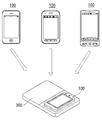
도 2는 본 발명의 실시예에 따른 이동 단말기들이 무선 충전 장치를 통하여 배터리를 무선으로 충전할 수 있음을 나타낸다.
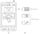
도 3은 사용자가 이동 단말기에서 제공하는, 배터리 충전 모드를 선택하기 위한 사용자 인터페이스를 나타낸다.
도 4는 본 발명에 따른 이동 단말기에서 제공하는, 배터리 충전 모드를 변경하기 위한 사용자 인터페이스를 나타낸다.
도 5는 본 발명에 따른 이동 단말기 및 무선 충전 장치의 개략적인 구성도를 나타낸다.
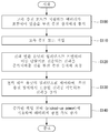
도 6은 본 발명에 따른 이동 단말기에서 수행되는 배터리 고속 충전 방법의 일예를 나타내는 흐름도이다.
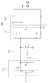
도 7은 본 발명에 따른 이동 단말기의 전력 픽업 유닛의 일예를 나타내는 회로도이다.
도 8 및 도 9는 본 발명에 따른 이동 단말기에서 배터리 충전 모드에 따라서 자기 유도 코일의 인덕턴스 값이 변경되는 예를 나타낸다.
도 10은 본 발명에 따른 이동 단말기에서 수행되는 배터리 고속 충전 방법의 다른 예를 나타내는 흐름도이다.
도 11은 도 10에 도시된 배터리 고속 충전 방법을 설명하기 위한 본 발명에 따른 이동 단말기의 전력 픽업 유닛의 블락도이다.
도 12는 본 발명에 따른 무선 충전 장치에서 수행되는 다른 전자 기기에 포함된 배터리 고속 충전 방법의 일예를 나타내는 흐름도이다.
도 13은 본 발명에 따른 무선 충전 장치의 전력 송신부의 일예를 나타내는 블락도이다.
도 14는 본 발명에 따른 무선 충전 장치의 전력 변환 유닛의 일예를 나타내는 회로도이다.1 is a block diagram of a mobile terminal according to an embodiment of the present invention.
2 shows that mobile terminals according to an embodiment of the present invention can wirelessly charge a battery through a wireless charging device.
3 illustrates a user interface for selecting a battery charging mode provided by a user in a mobile terminal.
4 illustrates a user interface for changing a battery charging mode provided by a mobile terminal according to the present invention.
5 is a schematic configuration diagram of a mobile terminal and a wireless charging device according to the present invention.
6 is a flowchart illustrating an example of a battery fast charging method performed in a mobile terminal according to the present invention.
7 is a circuit diagram illustrating an example of a power pickup unit of a mobile terminal according to the present invention.
8 and 9 illustrate an example in which an inductance value of a magnetic induction coil is changed according to a battery charging mode in a mobile terminal according to the present invention.
10 is a flowchart illustrating another example of a battery fast charging method performed in a mobile terminal according to the present invention.
FIG. 11 is a block diagram of a power pickup unit of a mobile terminal according to the present invention for explaining the fast charging method of the battery illustrated in FIG. 10.
12 is a flowchart illustrating an example of a battery fast charging method included in another electronic device performed by a wireless charging device according to the present invention.
13 is a block diagram illustrating an example of a power transmitter of the wireless charging apparatus according to the present invention.
14 is a circuit diagram illustrating an example of a power conversion unit of the wireless charging device according to the present invention.
본 발명의 상술한 목적, 특징들 및 장점은 첨부된 도면과 관련된 다음의 상세한 설명을 통하여 보다 분명해질 것이다. 이하 첨부된 도면을 참조하여 본 발명에 따른 바람직한 실시예들을 상세히 설명한다. 명세서 전체에 걸쳐서 동일한 참조번호들은 동일한 구성요소들을 나타낸다. 또한, 본 발명과 관련된 공지 기능 혹은 구성에 대한 구체적인 설명이 본 발명의 요지를 불필요하게 흐릴 수 있다고 판단되는 경우, 그 상세한 설명을 생략한다.The foregoing objects, features and advantages of the present invention will become more apparent from the following detailed description taken in conjunction with the accompanying drawings. DETAILED DESCRIPTION OF THE PREFERRED EMBODIMENTS Reference will now be made in detail to the preferred embodiments of the present invention, examples of which are illustrated in the accompanying drawings. Like numbers refer to like elements throughout. In the following description, well-known functions or constructions are not described in detail since they would obscure the invention in unnecessary detail.
이하, 본 발명과 관련된 이동단말기에 대하여 도면을 참조하여 보다 상세하게 설명한다. 이하의 설명에서 사용되는 구성요소에 대한 접미사 "모듈" 및 "부"는 명세서 작성의 용이함만이 고려되어 부여되거나 혼용되는 것으로서, 그 자체로 서로 구별되는 의미 또는 역할을 갖는 것은 아니다.Hereinafter, a mobile terminal related to the present invention will be described in detail with reference to the drawings. The suffix "module" and " part "for the components used in the following description are given or mixed in consideration of ease of specification, and do not have their own meaning or role.
본 명세서에서 설명되는 이동 단말기에는 휴대폰, 스마트 폰(smart phone), 노트북 컴퓨터(laptop computer), 디지털방송용 단말기, PDA(Personal Digital Assistants), PMP(Portable Multimedia Player), 네비게이션, 전용 단말기 등이 포함될 수 있다. 그러나 본 발명의 범위가 이에 한정되는 것은 아니다.The mobile terminal described herein may include a mobile phone, a smart phone, a laptop computer, a digital broadcasting terminal, a personal digital assistant (PDA), a portable multimedia player (PMP), navigation, a dedicated terminal, and the like. have. However, the scope of the present invention is not limited thereto.
도 1은 본 발명의 실시예에 따른 이동 단말기(100)의 블락도(block diagram)이다. 도 1을 참조하면, 상기 이동 단말기(100)는 무선 통신부(110), A/V(Audio/Video) 입력부(120), 사용자 입력부(130), 센싱부(140), 출력부(150), 저장부(160), 인터페이스부(170), 제어부(180) 및 전원부(190) 등을 포함할 수 있다. 도 1에 도시된 구성요소들이 필수적인 것은 아니어서, 이동 단말기(100)는 그보다 많은 구성요소들을 갖거나 그보다 적은 구성요소들을 가질 수도 있다.1 is a block diagram of a
이하, 상기 구성요소들에 대해 차례로 살펴본다.Hereinafter, the components will be described in order.
무선 통신부(110)는 이동 단말기(100)와 무선 통신 시스템 사이 또는 이동 단말기(100)와 이동 단말기(100)가 위치한 네트워크 사이의 무선 통신을 가능하게 하는 하나 이상의 모듈을 포함할 수 있다. 예를 들어, 무선 통신부(110)는 방송 수신 모듈(111), 이동통신 모듈(112), 무선 인터넷 모듈(113), 근거리 통신 모듈(114) 및 위치 정보 모듈(115) 등을 포함할 수 있다.The
방송 수신 모듈(111)은 방송 채널을 통하여 외부의 방송 관리 서버로부터 방송 신호 및/또는 방송 관련된 정보를 수신한다.The
상기 방송 채널은 위성 채널, 지상파 채널을 포함할 수 있다. 상기 방송 관리 서버는, 방송 신호 및/또는 방송 관련 정보를 생성하여 송신하는 서버 또는 기 생성된 방송 신호 및/또는 방송 관련 정보를 제공받아 단말기에 송신하는 서버를 의미할 수 있다. 상기 방송 신호는, TV 방송 신호, 라디오 방송 신호, 데이터 방송 신호를 포함할 뿐만 아니라, TV 방송 신호 또는 라디오 방송 신호에 데이터 방송 신호가 결합한 형태의 방송 신호도 포함할 수 있다.The broadcast channel may include a satellite channel and a terrestrial channel. The broadcast management server may refer to a server for generating and transmitting broadcast signals and / or broadcast related information, or a server for receiving broadcast signals and / or broadcast related information generated by the broadcast management server and transmitting the generated broadcast signals and / or broadcast related information. The broadcast signal may include a TV broadcast signal, a radio broadcast signal, a data broadcast signal, and a broadcast signal in which a data broadcast signal is combined with a TV broadcast signal or a radio broadcast signal.
상기 방송 관련 정보는, 방송 채널, 방송 프로그램 또는 방송 서비스 제공자에 관련한 정보를 의미할 수 있다. 상기 방송 관련 정보는, 이동통신망을 통하여도 제공될 수 있다. 이러한 경우에는 상기 이동통신 모듈(112)에 의해 수신될 수 있다.The broadcast-related information may refer to a broadcast channel, a broadcast program, or information related to a broadcast service provider. The broadcast related information may also be provided through a mobile communication network. In this case, it may be received by the
상기 방송 관련 정보는 다양한 형태로 존재할 수 있다. 예를 들어, DMB(Digital Multimedia Broadcasting)의 EPG(Electronic Program Guide) 또는 DVB-H(Digital Video Broadcast-Handheld)의 ESG(Electronic Service Guide) 등의 형태로 존재할 수 있다.The broadcast-related information may exist in various forms. For example, it may exist in the form of Electronic Program Guide (EPG) of Digital Multimedia Broadcasting (DMB) or Electronic Service Guide (ESG) of Digital Video Broadcast-Handheld (DVB-H).
상기 방송 수신 모듈(111)은, 각종 방송 시스템을 이용하여 방송 신호를 수신하는데, 특히, DMB-T(Digital Multimedia Broadcasting-Terrestrial), DMB-S(Digital Multimedia Broadcasting-Satellite), MediaFLO(Media Forward Link Only), DVB-H(Digital Video Broadcast-Handheld), ISDB-T(Integrated Services Digital Broadcast-Terrestrial) 등의 디지털 방송 시스템을 이용하여 디지털 방송 신호를 수신할 수 있다. 물론, 상기 방송 수신 모듈(111)은, 상술한 디지털 방송 시스템뿐만 아니라 방송 신호를 제공하는 다른 방송 시스템에 적합하도록 구성될 수도 있다.The
방송 수신 모듈(111)을 통해 수신된 방송 신호 및/또는 방송 관련 정보는 저장부(160)에 저장될 수 있다.The broadcast signal and / or broadcast related information received through the
이동통신 모듈(112)은 이동 통신망 상에서 기지국, 외부의 단말, 서버 중 적어도 하나와 무선 신호를 송수신한다. 상기 무선 신호는, 음성 콜(call) 신호, 화상 통화 콜 신호 또는 문자/멀티미디어 메시지 송수신에 따른 다양한 형태의 데이터를 포함할 수 있다.The
무선 인터넷 모듈(113)은 무선 인터넷 접속을 위한 모듈을 말하는 것으로, 무선 인터넷 모듈(113)은 이동 단말기(100)에 내장되거나 외장될 수 있다. 무선 인터넷 기술로는 WLAN(Wireless LAN)(Wi-Fi), Wibro(Wireless broadband), Wimax(World Interoperability for Microwave Access), HSDPA(High Speed Downlink Packet Access), LTE(Long Term Evolution) 등이 이용될 수 있다. The
근거리 통신 모듈(114)은 근거리 통신을 위한 모듈을 말한다. 근거리 통신 기술로 블루투스(Bluetooth), RFID(Radio Frequency Identification), 적외선 통신(IrDA, infrared Data Association), UWB(Ultra Wideband), ZigBee 등이 이용될 수 있다.The short
위치정보 모듈(115)은 이동 단말기의 위치를 확인하거나 얻기 위한 모듈이다. 상기 위치정보 모듈(115)은 범지구적 위성항법시스템(Global Navigation Satellite System, GNSS)를 이용하여 위치정보를 획득할 수 있다. 여기서, 범지구적 위성 항법 시스템(GNSS)은 지구를 공전하여 무선 항법 수신기들의 소정의 타입들이 지표면 또는 지표면 근처의 그들의 위치를 결정할 수 있는 기준 신호들을 보내는 무선 항법위성 시스템들을 설명하기 위해 이용되는 용어이다. 상기 범지구적 위성 항법 시스템(GNSS)에는 미국에서 운영하는 GPS(Global Position System), 유럽에서 운영하는 갈릴레오(Galileo), 러시아에서 운영하는 GLONASS(Global Orbiting Navigational Satelite System), 중국에서 운영하는 COMPASS 및 일본에서 운영하는 QZSS(Quasi-Zenith Satellite System)등이 있다.The
GNSS의 대표적인 예를 들면, 상기 위치정보 모듈(115)은 GPS(Global Position System) 모듈일 수 있다. 상기 GPS 모듈은, 일 지점(개체)이 3개 이상의 위성으로부터 떨어진 거리에 관한 정보와, 상기 거리 정보가 측정된 시간에 관한 정보를 산출한 다음 상기 산출된 거리 정보에 삼각법을 적용함으로써, 일 시간에 일 지점(개체)에 대한 위도, 경도, 및 고도에 따른 3차원의 위치 정보를 산출할 수 있다. 나아가, 3개의 위성을 이용하여 위치 및 시간 정보를 산출하고, 또 다른 1개의 위성을 이용하여 상기 산출된 위치 및 시간 정보의 오차를 수정하는 방법 또한 사용되고 있다. 상기 GPS 모듈은 현 위치를 실시간으로 계속 산출하고 그를 이용하여 속도 정보를 산출하기도 한다.As a representative example of the GNSS, the
도 1을 참조하면, A/V(Audio/Video) 입력부(120)는 오디오 신호 또는 비디오 신호 입력을 위한 것으로, 이에는 카메라(121)와 마이크(122) 등이 포함될 수 있다. 카메라(121)는 화상 통화 모드 또는 촬영 모드에서 이미지 센서에 의해 얻어지는 정지영상 또는 동영상 등의 화상 프레임을 처리한다. 처리된 화상 프레임은 디스플레이부(151)에 표시될 수 있다.Referring to FIG. 1, an A / V (Audio / Video)
카메라(121)에서 처리된 화상 프레임은 저장부(160)에 저장되거나 무선 통신부(110)를 통하여 외부로 전송될 수 있다. 카메라(121)는 단말기의 구성 태양에 따라 2개 이상이 구비될 수도 있다.The image frame processed by the
마이크(122)는 통화 모드 또는 녹음 모드, 음성 인식 모드 등에서 마이크로폰(Microphone)에 의해 외부의 음향 신호를 입력받아 전기적인 음성 데이터로 처리한다. 처리된 음성 데이터는 통화 모드인 경우 이동통신 모듈(112)을 통하여 이동통신 기지국으로 송신 가능한 형태로 변환되어 출력될 수 있다. 마이크(122)에는 외부의 음향 신호를 입력받는 과정에서 발생되는 잡음(noise)을 제거하기 위한 다양한 잡음 제거 알고리즘이 구현될 수 있다.The
사용자 입력부(130)는 사용자가 단말기의 동작 제어를 위한 입력 데이터를 발생시킨다. 사용자 입력부(130)는 키 패드(key pad) 돔 스위치 (dome switch), 터치 패드(정압/정전), 조그 휠, 조그 스위치 등으로 구성될 수 있다.The
센싱부(140)는 이동 단말기(100)의 개폐 상태, 이동 단말기(100)의 위치, 사용자 접촉 유무, 특정 부위에 대한 사용자의 터치 동작, 이동 단말기의 방위, 이동 단말기의 가속/감속 등과 같이 이동 단말기(100)의 현 상태를 감지하여 이동 단말기(100)의 동작을 제어하기 위한 센싱 신호를 발생시킨다. 이러한 센싱 신호는 상기 제어부(180)에 전달되어, 상기 제어부(180)가 특정 기능을 수행하는 기초가 될 수 있다.The
상기 센싱부(140)는 사용자의 터치 여부를 감지하기 위한 터치 센서, 상기 사용자의 터치에 기초하여 발생하는 진동을 감지하기 위한 진동 센서, 상기 이동 단말기(100)의 회전을 감지하는 자이로(gyro) 센서, 가속도 센서, 지자기 센서 등을 포함할 수 있다. 그러나 본 발명의 범위가 이에 한정되는 것은 아니다.The
예를 들어 이동 단말기(100)가 슬라이드 폰 형태인 경우 슬라이드 폰의 개폐 여부를 센싱할 수 있다. 또한, 전원부(190)의 전원 공급 여부, 인터페이스부(170)의 외부 기기 결합 여부 등과 관련된 센싱 기능을 담당할 수도 있다. 한편, 상기 센싱부(140)는 근접 센서를 포함할 수 있다.For example, when the
출력부(150)는 시각, 청각 또는 촉각 등과 관련된 출력을 발생시키기 위한 것으로, 이에는 디스플레이부(151), 음향 출력부(152), 알람부(153) 및 햅틱 모듈(154) 등이 포함될 수 있다.The
디스플레이부(151)는 이동 단말기(100)에서 처리되는 정보를 표시 출력한다. 예를 들어, 이동 단말기가 통화 모드인 경우 통화와 관련된 UI(User Interface) 또는 GUI(Graphic User Interface)를 표시한다. 이동 단말기(100)가 화상 통화 모드 또는 촬영 모드인 경우에는 촬영 또는/및 수신된 영상 또는 UI, GUI를 표시한다. The
디스플레이부(151)는 액정 디스플레이(liquid crystal display), 박막 트랜지스터 액정 디스플레이(thin film transistor-liquid crystal display), 유기 발광 다이오드(organic light-emitting diode), 플렉시블 디스플레이(flexible display), 3차원 디스플레이(3D display) 중에서 적어도 하나를 포함할 수 있다. The
이들 중 일부 디스플레이는 그를 통해 외부를 볼 수 있도록 투명형 또는 광투과형으로 구성될 수 있다. 이는 투명 디스플레이라 호칭될 수 있는데, 상기 투명 디스플레이의 대표적인 예로는 투명 LCD 등이 있다. 디스플레이부(151)의 후방 구조 또한 광 투과형 구조로 구성될 수 있다. 이러한 구조에 의하여, 사용자는 단말기 바디의 디스플레이부(151)가 차지하는 영역을 통해 단말기 바디의 후방에 위치한 사물을 볼 수 있다.Some of these displays may be transparent or light transmissive so that they can be seen through. This may be referred to as a transparent display. A typical example of the transparent display is a transparent LCD or the like. The rear structure of the
이동 단말기(100)의 구현 형태에 따라 디스플레이부(151)가 2개 이상 존재할 수 있다. 예를 들어, 이동 단말기(100)에는 복수의 디스플레이부들이 하나의 면에 이격되거나 일체로 배치될 수 있고, 또한 서로 다른 면에 각각 배치될 수도 있다. There may be two or
디스플레이부(151)와 터치 동작을 감지하는 센서(이하, '터치 센서'라 함)가 상호 레이어 구조를 이루는 경우(이하, '터치 스크린'이라 함)에, 디스플레이부(151)는 출력 장치 이외에 입력 장치로도 사용될 수 있다. 터치 센서는, 예를 들어, 터치 필름, 터치 시트, 터치 패드 등의 형태를 가질 수 있다.When the
터치 센서는 디스플레이부(151)의 특정 부위에 가해진 압력 또는 디스플레이부(151)의 특정 부위에 발생하는 정전 용량 등의 변화를 전기적인 입력신호로 변환하도록 구성될 수 있다. 터치 센서는 터치 되는 위치 및 면적뿐만 아니라, 터치 시의 압력까지도 검출할 수 있도록 구성될 수 있다.The touch sensor may be configured to convert a change in a pressure applied to a specific portion of the
터치 센서에 대한 터치 입력이 있는 경우, 그에 대응하는 신호(들)는 터치 제어기로 보내진다. 터치 제어기는 그 신호(들)를 처리한 다음 대응하는 데이터를 제어부(180)로 전송한다. 이로써, 제어부(180)는 디스플레이부(151)의 어느 영역이 터치 되었는지 여부 등을 알 수 있게 된다.If there is a touch input to the touch sensor, the corresponding signal (s) is sent to the touch controller. The touch controller processes the signal (s) and transmits the corresponding data to the
상기 터치스크린에 의해 감싸지는 이동 단말기의 내부 영역 또는 상기 터치스크린의 근처에 근접 센서가 배치될 수 있다. 상기 근접 센서는 소정의 검출면에 접근하는 물체, 혹은 근방에 존재하는 물체의 유무를 전자계의 힘 또는 적외선을 이용하여 기계적 접촉이 없이 검출하는 센서를 말한다. 근접 센서는 접촉식 센서보다는 그 수명이 길며 그 활용도 또한 높다.A proximity sensor may be disposed in an inner region of the mobile terminal or in the vicinity of the touch screen that is wrapped by the touch screen. The proximity sensor refers to a sensor that detects the presence or absence of an object approaching a predetermined detection surface or a nearby object without mechanical contact using the force of an electromagnetic field or infrared rays. The proximity sensor has a longer life span than the contact sensor and its utilization is also high.
상기 근접 센서의 예로는 투과형 광전 센서, 직접 반사형 광전 센서, 미러 반사형 광전 센서, 고주파 발진형 근접 센서, 정전용량형 근접 센서, 자기형 근접 센서, 적외선 근접 센서 등이 있다.Examples of the proximity sensor include a transmission photoelectric sensor, a direct reflection photoelectric sensor, a mirror reflection photoelectric sensor, a high frequency oscillation proximity sensor, a capacitive proximity sensor, a magnetic proximity sensor, and an infrared proximity sensor.
상기 터치 스크린이 정전식인 경우에는 상기 커서의 근접에 따른 전계의 변화로 상기 커서의 근접을 검출하도록 구성된다. 이 경우 상기 터치 스크린(터치 센서)은 근접 센서로 분류될 수도 있다.And to detect the proximity of the cursor with the change of the electric field along the proximity of the cursor when the touch screen is electrostatic. In this case, the touch screen (touch sensor) may be classified as a proximity sensor.
상기 근접센서는, 근접 터치 및 근접 터치 패턴(예를 들어, 근접 터치 거리, 근접 터치 방향, 근접 터치 속도, 근접 터치 시간, 근접 터치 위치, 근접 터치 이동 상태 등)을 감지한다. 상기 감지된 근접 터치 동작 및 근접 터치 패턴에 상응하는 정보는 터치 스크린 상에 출력될 수 있다.The proximity sensor detects a proximity touch and a proximity touch pattern (e.g., a proximity touch distance, a proximity touch direction, a proximity touch speed, a proximity touch time, a proximity touch position, a proximity touch movement state, and the like). Information corresponding to the detected proximity touch operation and the proximity touch pattern may be output on the touch screen.
음향 출력부(152)는 콜 신호 수신, 통화모드 또는 녹음 모드, 음성인식 모드, 방송수신 모드 등에서 무선 통신부(110)로부터 수신되거나 저장부(160)에 저장된 오디오 데이터를 출력할 수도 있다. 음향 출력부(152)는 이동 단말기(100)에서 수행되는 기능(예를 들어, 콜 신호 수신음, 메시지 수신음 등)과 관련된 음향 신호를 출력한다. 이러한 음향 출력부(152)에는 리시버(Receiver), 스피커(speaker), 버저(Buzzer) 등이 포함될 수 있다. 또한 상기 음향 출력부(152)는 이어폰잭(116)을 통해 음향을 출력할 수 있다. 사용자는 상기 이어폰잭(116)에 이어폰을 연결하여 출력되는 음향을 들을 수 있다.The
알람부(153)는 이동 단말기(100)의 이벤트 발생을 알리기 위한 신호를 출력할 수 있다. 이동 단말기에서 발생 되는 이벤트의 예로는 콜 신호 수신, 메시지 수신, 키 신호 입력, 터치 입력 등이 있다. 알람부(153)는 비디오 신호나 오디오 신호 이외에 다른 형태, 예를 들어 진동으로 이벤트 발생을 알리기 위한 신호를 출력할 수도 있다. 비디오 신호나 오디오 신호는 디스플레이부(151)나 음향 출력부(152)를 통해서도 출력될 수 있다.The
햅틱 모듈(haptic module, 154)은 사용자가 느낄 수 있는 다양한 촉각 효과를 발생시킨다. 햅틱 모듈(154)이 발생시키는 촉각 효과의 대표적인 예로는 진동이 있다. 햅택 모듈(154)이 발생하는 진동의 세기와 패턴 등은 제어가능하다. 예를 들어, 서로 다른 진동을 합성하여 출력하거나 순차적으로 출력할 수도 있다.The
햅틱 모듈(154)은, 진동 외에도, 접촉 피부면에 대해 수직 운동하는 핀 배열에 의한 자극에 의한 효과, 분사구나 흡입구를 통한 공기의 분사력이나 흡입력을 통한 자극에 의한 효과, 피부 표면을 스치는 자극에 의한 효과, 전극(eletrode)의 접촉을 통한 자극에 의한 효과, 정전기력을 이용한 자극에 의한 효과, 흡열이나 발열 가능한 소자를 이용한 냉온감 재현에 의한 효과 등 다양한 촉각 효과를 발생시킬 수 있다.In addition to the vibration, the
햅틱 모듈(154)은 직접적인 접촉을 통해 촉각 효과의 전달할 수 있을 뿐만 아니라, 사용자의 손가락이나 팔 등의 근 감각을 통해 촉각 효과를 느낄 수 있도록 구현할 수도 있다. 햅틱 모듈(154)은 휴대 단말기(100)의 구성 태양에 따라 2개 이상이 구비될 수 있다.The
저장부(160)는 제어부(180)의 동작을 위한 프로그램을 저장할 수 있고, 입/출력되는 데이터들(예를 들어, 폰북, 메시지, 정지영상, 동영상 등)을 임시 저장할 수도 있다. 상기 저장부(160)는 상기 터치스크린 상의 터치 입력시 출력되는 다양한 패턴의 진동 및 음향에 관한 데이터를 저장할 수 있다.The
저장부(160)는 플래시 메모리 타입(flash memory type), 하드디스크 타입(hard disk type), 멀티미디어 카드 마이크로 타입(multimedia card micro type), 카드 타입의 메모리(예를 들어 SD 또는 XD 메모리 등), 램(Random Access Memory, RAM), SRAM(Static Random Access Memory), 롬(Read-Only Memory, ROM), EEPROM(Electrically Erasable Programmable Read-Only Memory), PROM(Programmable Read-Only Memory) 자기 메모리, 자기 디스크, 광디스크 중 적어도 하나의 타입의 저장매체를 포함할 수 있다. 이동 단말기(100)는 인터넷(internet)상에서 상기 저장부(160)의 저장 기능을 수행하는 웹 스토리지(web storage)와 관련되어 동작할 수도 있다.The
인터페이스부(170)는 이동 단말기(100)에 연결되는 모든 외부기기와의 통로 역할을 한다. 인터페이스부(170)는 외부 기기로부터 데이터를 전송받거나 전원을 공급받아 이동 단말기(100) 내부의 각 구성 요소에 전달하거나 이동 단말기(100) 내부의 데이터가 외부 기기로 전송되도록 한다.The
예를 들어, 유/무선 헤드셋 포트, 외부 충전기 포트, 유/무선 데이터 포트, 메모리 카드(memory card) 포트, 식별 모듈이 구비된 장치를 연결하는 포트, 오디오 I/O(Input/Output) 포트, 비디오 I/O(Input/Output) 포트, 이어폰 포트 등이 인터페이스부(170)에 포함될 수 있다.For example, a wired / wireless headset port, an external charger port, a wired / wireless data port, a memory card port, a port for connecting a device having an identification module, an audio I / O port, A video input / output (I / O) port, an earphone port, and the like may be included in the
상기 인터페이스부(170)는 상기 카드 형식의 사용자 식별 모듈이 장착될 수 있는 카드 슬롯을 포함할 수 있다. 그러면, 상기 사용자 식별 모듈은 상기 카드 슬롯을 통하여 이동 단말기(100)와 연결될 수 있다. 이때, 상기 인터페이스부(170)에는 복수의 사용자 식별 모듈이 연결될 수 있다.The
상기 인터페이스부(170)는 이동단말기(100)가 외부 크래들(cradle)과 연결될 때 상기 크래들로부터의 전원이 상기 이동단말기(100)에 공급되는 통로가 되거나, 사용자에 의해 상기 크래들에서 입력되는 각종 명령 신호가 상기 이동단말기로 전달되는 통로가 될 수 있다. 상기 크래들로부터 입력되는 각종 명령 신호 또는 상기 전원은 상기 이동단말기가 상기 크래들에 정확히 장착되었음을 인지하기 위한 신호로 동작될 수도 있다.When the
제어부(180)는 통상적으로 이동 단말기의 전반적인 동작을 제어한다. 예를 들어 음성 통화, 데이터 통신, 화상 통화 등을 위한 관련된 제어 및 처리를 수행한다. 제어부(180)는 멀티 미디어 재생을 위한 멀티미디어 모듈(181)을 구비할 수도 있다. 멀티미디어 모듈(181)은 제어부(180) 내에 구현될 수도 있고, 제어부(180)와 별도로 구현될 수도 있다.The
상기 제어부(180)는 상기 터치스크린 상에서 행해지는 필기 입력 또는 그림 그리기 입력을 각각 문자 및 이미지로 인식할 수 있는 패턴 인식 처리를 행할 수 있다.The
전원부(190)는 제어부(180)의 제어에 의해 외부의 전원, 내부의 전원을 인가받아 각 구성요소들의 동작에 필요한 전원을 공급한다. 상기 전원부(190)는 자기 유도 방식(magnetic induction method)에 의하여 무선 충전 장치로부터 전력을 수신하여 배터리(195)를 충전할 수 있다. 상기 전원부(190)는 일반 충전 모드(normal charging mode)로 상기 배터리를 충전할 수도 있고, 고속 충전 모드(fast charging mode)로 상기 배터리를 충전할 수도 있다.Under the control of the
상기 전원부(190)의 전력 수신부(power receiver, 200)는 상기 무선 충전 장치로부터의 수신 전력에 기초하여 상기 배터리(195)에 대한 충전 전압을 발생할 수 있다. 상기 제어부(180)는 충전 모드에 따라서, 상기 전력 수신부(200)에서 자기 유도에 관여된 적어도 하나의 소자의 임피던스를 제어함으로써 상기 무선 충전 장치로부터의 수신 전력을 제어하고, 상기 제어된 수신 전력에 기초하여 상기 배터리(195)의 충전 속도를 제어할 수 있다. 상기 전원부(190)의 상기 배터리(195)에 대한 충전 동작에 대해서는 향후, 도 2 내지 도 14를 참조하여 보다 상세히 설명한다.The
여기에 설명되는 다양한 실시예는 예를 들어, 소프트웨어, 하드웨어 또는 이들의 조합된 것을 이용하여 컴퓨터 또는 이와 유사한 장치로 읽을 수 있는 기록매체 내에서 구현될 수 있다.The various embodiments described herein may be embodied in a recording medium readable by a computer or similar device using, for example, software, hardware, or a combination thereof.
하드웨어적인 구현에 의하면, 여기에 설명되는 실시예는 ASICs (application specific integrated circuits), DSPs (digital signal processors), DSPDs (digital signal processing devices), PLDs (programmable logic devices), FPGAs (field programmable gate arrays, 프로세서(processors), 제어기(controllers), 마이크로 컨트롤러(micro-controllers), 마이크로 프로세서(microprocessors), 기능 수행을 위한 전기적인 유닛 중 적어도 하나를 이용하여 구현될 수 있다. 일부의 경우에 그러한 실시예들이 제어부(180)에 의해 구현될 수 있다.According to a hardware implementation, the embodiments described herein may be implemented as application specific integrated circuits (ASICs), digital signal processors (DSPs), digital signal processing devices (DSPDs), programmable logic devices (PLDs), field programmable gate arrays May be implemented using at least one of processors, controllers, micro-controllers, microprocessors, and electrical units for performing functions. In some cases, And may be implemented by the
소프트웨어적인 구현에 의하면, 절차나 기능과 같은 실시예들은 적어도 하나의 기능 또는 작동을 수행하게 하는 별개의 소프트웨어 모듈과 함께 구현될 수 있다. 소프트웨어 코드는 적절한 프로그램 언어로 쓰여진 소프트웨어 어플리케이션에 의해 구현될 수 있다. 또한, 소프트웨어 코드는 저장부(160)에 저장되고, 제어부(180)에 의해 실행될 수 있다.According to a software implementation, embodiments such as procedures or functions may be implemented with separate software modules that perform at least one function or operation. The software code may be implemented by a software application written in a suitable programming language. Also, the software codes may be stored in the
이상에서는 도 1을 참조하여, 본 발명에 따른 이동 단말기(100)의 구성에 대하여 살펴 보았다. 이하에서는, 도 2 내지 도 11을 참조하여 본 발명에 따른 이동 단말기(100)의 배터리 고속 충전 기능에 대하여 보다 구체적으로 살펴 본다. 또한, 도 12 내지 도 14를 참조하여서는 상기 이동 단말기(100)를 포함하는 전자 기기의 배터리를 고속으로 충전시킬 수 있는 본 발명에 따른 무선 충전 장치(300)에 대해 보다 상세히 살펴 본다.In the above, the configuration of the
도 2는 본 발명의 실시예에 따른 이동 단말기들(100)이 무선 충전 장치(300)를 통하여 배터리(195)를 무선으로 충전할 수 있음을 나타낸다. 도 2를 참조하면, 상기 이동 단말기들(100)은 충전 기능이 활성화된 상기 무선 충전 장치(300) 상에 배치됨으로써, 상기 무선 충전 장치(300)로부터 자기 유도 방식에 따라 전력을 수신하고, 상기 수신된 전력에 기초하여 상기 배터리(195)를 충전시킬 수 있다.2 shows that the
상기 무선 충전 장치(300)는 상기 이동 단말기(100)로부터 배터리(195)의 고속 충전이 요청되는 경우에는 상기 이동 단말기(100)로 전송되는 전력을 증가시킬 수 있다. 한편, 상기 무선 충전 장치(300)는 상기 이동 단말기(100)의 무선 통신부(110)를 통한 무선 통신에 기초하여 상기 이동 단말기(100)의 고속 충전 요청을 수신할 수도 있고, 상기 이동 단말기(100)의 전원부(190)에 포함된 전력 수신부(200)를 통한 무선 통신에 기초하여 상기 이동 단말기(100)의 고속 충전 요청을 수신할 수도 있다.When the fast charging of the
상기 배터리(195)의 고속 충전이 필요한 경우에도, 상기 무선 충전 장치(300)는 배터리(195)의 충전 모드에 상관없이 동일한 전력을 전송할 수 있다. 다만, 이때에는 상기 이동 단말기(100)는 상기 무선 충전 장치(300)로부터 전송된 전력 중 픽업되는 전력(즉, 수신 전력, picked-up power)을 증가시킬 수 있다.Even when fast charging of the
본 발명의 구현 형태에 따라서는, 상기 배터리(195)의 고속 충전이 필요한 경우, 상기 무선 충전 장치(300)의 송신 전력 및 상기 이동 단말기(100)에서의 수신 전력 모두가 증가될 수도 있다.According to an embodiment of the present invention, when the fast charging of the
도 3은 사용자가 이동 단말기(100)에서 제공하는, 배터리 충전 모드를 선택하기 위한 사용자 인터페이스를 나타낸다. 도 3의 (a)를 참조하면, 상기 이동 단말기(100)에서는 일반 충전 모드 및 고속 충전 모드를 제공하는 것을 알 수 있다. 도 3의 (a)에 도시된 바와 같이, 사용자가 고속 충전 모드를 선택하면, 상기 이동 단말기(100)에는 도 3의 (b)에 도시된 바와 같은, 고속 충전 중임을 나타내는 인디케이터(indicator)를 인디케이터 영역에 표시할 수 있다.3 illustrates a user interface for selecting a battery charging mode provided by a user in the
도 3에 도시된 바와 같이, 배터리(195)의 고속 충전은 사용자의 선택에 의하여 실행될 수 있다. 그러나, 본 발명의 다른 구현 형태 따르면, 상기 이동 단말기(100)는 상기 배터리(195)의 충전 레벨이 미리 정해진 레벨 이하인 경우에는 자동으로 고속 충전 모드로 상기 배터리(195)를 충전할 수도 있다.As shown in FIG. 3, fast charging of the
도 4는 본 발명에 따른 이동 단말기(100)에서 제공하는, 배터리 충전 모드를 변경하기 위한 사용자 인터페이스를 나타낸다. 도 4를 참조하면, 상기 이동 단말기(100)는 상기 배터리(195)의 충전 레벨이 소정의 레벨(즉, 75%)에 도달하면, 배터리(195) 충전 모드를 고속 충전 모드로 유지할지를 선택할 수 있음을 알 수 있다.4 illustrates a user interface for changing a battery charging mode provided by the
한편, 본 발명의 다른 구현 형태에 따르면, 상기 이동 단말기(100)는 상기 배터리(195)의 충전 레벨이 소정의 레벨에 도달할 경우, 자동으로 배터리(195) 충전 모드를 고속 충전 모드에서 일반 충전 모드로 전환할 수도 있다. 왜냐하면, 고속 충전 모드에서의 충전 효율이 일반 충전 모드에서의 충전 효율보다 낮을 수 있기 때문이다.Meanwhile, according to another embodiment of the present invention, the
도 5는 본 발명에 따른 이동 단말기(100) 및 무선 충전 장치(300)의 개략적인 구성도를 나타낸다. 도 5에서는 상기 이동 단말기(100) 및 무선 충전 장치(300) 각각의 구성요소 중 배터리(195) 충전에 관여되는 필요한 구성요소만이 간략 기재되었다.5 shows a schematic configuration diagram of a
상기 무선 충전 장치(300)는 시스템 유닛(system unit, 305)으로부터 전력을 공급받고, 상기 공급된 전력에 기초하여 자기 유도 방식으로 상기 이동 단말기(100)로 전력을 송신하기 위한 복수의 전력 송신부(power transmitter, 310 및 340)를 포함할 수 있다. 상기 복수의 전력 송신부(310 및 340) 각각은 서로 다른 이동 단말기에 포함된 배터리를 충전하는데 이용될 수 있다.The
상기 복수의 전력 송신부(310 및 340)의 기능 및 구성은 서로 동일 또는 유사할 수 있다. 그러므로 하나의 전력 송신부(310)에 대해서만 그 기능 및 동작에 대해 살펴 본다. 상기 전력 송신부(310)는 전력 변환 유닛(320) 및 통신 제어 유닛(330)을 포함한다. 상기 전력 변환 유닛(320)은 자기 유도 방식에 따라 수신되는 전력을 상기 이동 단말기(100)로 전송할 수 있다. 상기 통신 제어 유닛(330)은 상기 시스템 유닛(305)의 제어하에 상기 전력 변환 유닛(320)의 동작을 제어하거나, 상기 전력 변환 유닛(320)을 통하여 송수신되는 신호를 이용하여 상기 이동 단말기(100)와의 통신을 수행할 수 있다. The functions and configurations of the plurality of
한편, 상기 통신 제어 유닛(330)은 상기 이동 단말기(100)의 배터리(195) 충전 모드에 기초하여 상기 전력 변환 유닛(320)의 임피던스를 변경함으로써 상기 이동 단말기(100)로 전송되는 전력을 증가시킬 수 있다. 보다 구체적으로, 상기 통신 제어 유닛(330)은 고속 충전 모드에서는 상기 전력 변환 유닛(320)의 자기 유도 코일(321)의 임피던스를 증가시킴으로써 상기 이동 단말기(100)로 전송되는 전력을 증가시킬 수 있다. 상기 자기 유도 코일(311)은 자기 유도 방식에 따르면, 자기장을 유도하는 1차 코일(Primary Coil)에 해당된다.Meanwhile, the
도 5에서는 상기 전력 송신부(310)의 통신 및 제어 유닛(330)이 상기 이동 단말기(100)와의 통신 기능 및 상기 전력 송신부(310)에 대한 제어 기능을 모두 수행할 수 있다. 그러나 본 발명의 다른 구현 형태에 따르면, 상기 전력 송신부(310)는 서로 분리된 제어 유닛과 무선 통신 유닛을 포함할 수도 있다. 또한, 상기 전력 송신부(310)의 제어 유닛은 상기 무선 충전 장치(300) 전체의 동작을 제어하는 제어부(미도시)의 일부를 구성할 수도 있다.In FIG. 5, the communication and
상기 이동 단말기(100)는 전력 수신부(200) 및 배터리(195)를 포함할 수 있다. 상기 전력 수신부(200)는 전력 픽업 유닛(210) 및 통신 제어 유닛(220)을 포함할 수 있다. 상기 전력 픽업 유닛(210)은 자기 유도 코일(211)을 통하여 상기 무선 충전 장치(300)에서 송신된 전력을 수신하고, 수신된 전력에 기초하여 배터리(195)를 충전하기 위한 전압을 발생하여 상기 배터리(195)를 충전시킬 수 있다.The
상기 통신 제어 유닛(220)은 상기 전력 픽업 유닛(210)의 동작을 제어할 수 있고, 상기 전력 픽업 유닛(210)을 통하여 송수신되는 신호를 이용하여 상기 무선 충전 장치(300)와의 통신을 수행할 수 있으며, 상기 배터리(195)의 상태를 센싱하거나 상기 배터리(195)의 충전 동작을 직접 제어할 수도 있다.The
한편, 상기 통신 제어 유닛(220)은 상기 이동 단말기(100)의 배터리(195) 충전 모드에 기초하여 상기 전력 픽업 유닛(210)의 임피던스를 변경함으로써 상기 이동 단말기(100)가 수신하는 전력을 증가시킬 수 있다. 보다 구체적으로, 상기 통신 제어 유닛(220)은 고속 충전 모드에서는 상기 전력 픽업 유닛(210)의 자기 유도 코일(211)의 임피던스를 증가시킴으로써 상기 이동 단말기(100)에서 수신하는 전력을 증가시킬 수 있다. 상기 자기 유도 코일(211)은 자기 유도 방식에 따르면, 자기장을 유도하는 2차 코일(Secondary Coil)에 해당된다.Meanwhile, the
한편, 도 5에서는 상기 전력 수신부(200)의 통신 및 제어 유닛(220)이 상기 무선 충전 장치(300)와의 통신 기능 및 상기 전력 수신부(200)에 대한 제어 기능을 모두 수행할 수 있다. 그러나 본 발명의 다른 구현 형태에 따르면, 상기 전력 수신부(200)는 서로 분리된 제어 유닛과 무선 통신 유닛을 포함할 수도 있다. 또한, 상기 전력 수신부(200)의 제어 유닛은 상기 이동 단말기(100) 전체의 동작을 제어하는 제어부(180)의 일부를 구성할 수도 있다.Meanwhile, in FIG. 5, the communication and
도 6은 본 발명에 따른 이동 단말기(100)에서 수행되는 배터리 고속 충전 방법의 일예를 나타내는 흐름도이다. 이하, 필요한 도면들을 참조하여 상기 배터리 고속 충전 방법을 설명한다.6 is a flowchart illustrating an example of a battery fast charging method performed in the
먼저, 상기 이동 단말기(100)의 통신 및 제어 유닛(220)은 상기 이동 단말기(100)에 고속 충전 모드를 지원하는 배터리가 포함되어 있음을 무선 충전 장치(300)에게 통지한다(S100). 상기 이동 단말기(100)가 상기 무선 충전 장치(300)로 고속 충전 모드를 지원하는 배터리의 내장을 통지하는 방법은, 무선 통신부(110)를 통한 근거리 무선 통신을 이용하는 방법과 전력 픽업 유닛(210)을 통한 무선 통신을 이용하는 방법이 이용될 수 있다.First, the communication and
그런 다음, 상기 이동 단말기(100)는 고속 충전 모드로 진입하며(S110), 전력 변환 유닛(320)의 임피던스를 가변하여 상기 이동 단말기(100)로 전송되는 전력을 증가시켜줄 것을 상기 무선 충전 장치(300)에 요청함과 동시에(S120), 전력 픽업 유닛(210)의 임피던스를 제어하여 상기 무선 충전 장치(300)에서 전송된 전력 중 픽업되는 전력을 일반 충전 모드 시보다 증가시킨다(S130).Then, the
그런 다음, 상기 이동 단말기(100)는 상기 증가된 픽업 전력에 기초하여 상기 배터리(195)의 충전 속도를 증가시킬 수 있다(S140). 예컨대, 상기 이동 단말기(100)의 통신 및 제어 유닛(220)은 상기 증가된 픽업 전력에 기초하여 상기 배터리(195)로 제공되는 충전 전압을 증가시킴으로써 상기 배터리(195)의 충전 속도를 증가시킬 수 있다. 이하에서는 도 7 내지 도 9를 참조하여, 상기 이동 단말기(100)에서 고속 충전 모드를 수행하는 구체적인 예들을 살펴 본다.Then, the
도 7은 본 발명에 따른 이동 단말기(100)의 전력 픽업 유닛(210)의 일예를 나타내는 회로도이다. 도 7에 도시된 상기 전력 픽업 유닛(210)의 구성요소들은 필수적인 것들이 아니다. 그러므로 본 발명의 구현 형태에 따라, 상기 전력 픽업 유닛(210)에는 도시된 것 이외의 구성요소가 포함될 수도 있으며, 도시된 구성요소가 포함되지 않을 수도 있다.7 is a circuit diagram illustrating an example of the
도 7을 참조하면, 상기 전력 픽업 유닛(210)은 자기 유도 코일(211), 상기 자기 유도 코일(Ls, 211)와 듀얼 공진 회로(dual resonant circuit, 215)를 구성하는 커패시터들(Cs 및 Cd), 통신 모듈레이터(communication modulator, 216), 정류 회로(217), 및 출력 차단부(output disconnect, 218)를 포함하는 것을 알 수 있다.Referring to FIG. 7, the
상기 자기 유도 코일(211)은 무선 충전 장치(300)에서 전송된 전력을 자기 유도 방식에 따라 수신할 수 있다. 상기 자기 유도 코일(211)에 직렬로 연결된 커패시터(Cs)는 전력 전송 효율을 증가시키기 위한 커패시터이며, 상기 자기 유도 코일(211)에 병렬로 연결된 커패시터(Cd)는 공진 검출 방식을 가능케 하는 커패시터이다. 이러한 자기 유도 코일(211) 및 커패시터들(Cs 및 Cd)의 기능 및 동작은 본 발명이 속하는 기술분야에서 통상의 지식을 가진 자에게는 자명한 사항이라 할 것인바, 이들에 대한 상세한 설명은 생략한다. 더욱이, 이러한 듀얼 공진 구성은 무선 충전 표준인 치(Qi)의 스펙(specification)에 상세히 기술되어 있다.The
그러나, 도 7을 참조하면, 본 발명에 따른 이동 단말기(100)에서 상기 자기 유도 코일(211) 및 커패시터들(Cs 및 Cd)의 용량이 가변적임을 알 수 있다. 이는 상기 이동 단말기(100)의 배터리(195) 충전 모드와 관련된다. 예컨대, 상기 이동 단말기(100)에서 통신 및 제어 유닛(220)은 배터리(195) 충전 모드에 따라서 상기 자기 유도 코일(211) 및 커패시터들(Cs 및 Cd)의 용량을 가변할 수 있다.However, referring to FIG. 7, it can be seen that the capacity of the
보다 상세하게는, 상기 통신 및 제어 유닛(220)은 고속 충전 모드에서는 상기 자기 유도 코일(211)의 인덕턴스를 증가시켜 상기 자기 유도 코일(211)에 의하여 유도되는 전압의 크기를 증가시킴으로써 픽업 전력을 증가시킬 수 있다. 증가된 픽업 전력은 상기 배터리(195)의 충전 속도를 증가시키는 기초가 될 수 있다. 물론, 상기 자기 유도 코일(211)의 인덕턴스 값이 증가되면, 그에 따라 상기 커패시터들(Cs 및 Cd)의 용량 역시 그 용도에 따라 변경될 수 있다.More specifically, the communication and
또한, 상기 통신 및 제어 유닛(220)는 배터리(195)의 고속 충전을 구현하기 위하여 상기 커패시터들(Cs 및 Cd)의 용량을 변경할 수도 있다. 이때에도, 상기 커패시터들(Cs 및 Cd)의 변경분을 반영하여 상기 자기 유도 코일(211)의 용량 역시 변경될 수 있다.In addition, the communication and
상기 통신 모듈레이터(216)는 무선 충전 장치(300)로부터 전송된 전력 신호(power signal)에 기초하여 프라이머리 셀 전류(primary cell current) 및/또는 프라이머리 셀 전압(primary cell voltage)를 모듈레이트할 수 있다. 이러한 통신 모듈레이터(216)의 구조, 기능, 및 동작에 대해서도 무선 충전 표준인 치(Qi)의 스펙에 상세히 설명되어 있는바, 이에 대한 상세한 설명은 생략한다.The
상기 정류 회로(217)는 상기 듀얼 공진 회로(215)로부터 출력되는 교류 신호를 직류 신호로 정류하여 직류 신호로 변환하여 출력할 수 있다. 상기 출력 차단부(218)는 통신 및 제어 유닛(220)의 제어하에 상기 정류 회로(217)의 출력단의 상기 배터리(195)로의 연결 여부를 결정한다. 예컨대, 상기 통신 및 제어 유닛(220)은 무선 충전 장치(300)로부터 충분한 전력이 공급되지 않은 경우에는 상기 출력 차단부(218)의 개방 상태를 유지할 수 있다.The
이하, 도 6에 도시된 배터리(195) 고속 충전 방법을 도 7에 도시된 전력 픽업 유닛(210)에 적용해 본다. 고속 충전 모드에서 상기 통신 및 제어 유닛(220)은 상기 자기 유도 코일(211)의 인덕턴스를 증가시키고, 상기 자기 유도 코일(211)의 증가분을 반영하여 상기 듀얼 공진 회로(215)에 포함된 커패시터들(Cs 및 Cd)의 용량으 가변한다. 그러면, 상기 듀얼 공진 회로(215)로부터 출력되는 교류 전압은 일반 충전 모드 시보다 증가한다. 그러면, 상기 정류 회로(217)를 통하여 출력되는 직류 전압 역시 증가하며, 최종적으로 배터리(195)에 공급되는 충전 전압 역시 증가하게 되어 상기 배터리(195)의 충전 속도가 빨라질 수 있다.Hereinafter, the fast charging method of the
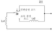
도 8 및 도 9는 본 발명에 따른 이동 단말기(100)에서 배터리(195) 충전 모드에 따라서 자기 유도 코일(211)의 인덕턴스 값이 변경되는 예를 나타낸다. 도 8을 참조하면, 일반 충전 모드에서는 상기 자기 유도 코일(211)의 인덕턴스 값은 하나의 코일(Ls1)에 의해 결정되나, 고속 충전 모드에서는 서로 직렬로 연결된 두 개의 코일(Ls1 및 Ls2)에 의해 결정됨을 알 수 있다.8 and 9 illustrate an example in which an inductance value of the
도 9의 (a)는 일반 충전 모드에서 상기 자기 유도 코일(211)의 인덕턴스 값을 결정하는, 미리 정해진 내경(di), 외경(do), 및 두께(dc)를 갖는, 기본 코일을 나타낸다. 도 9의 (b)는 제1 고속 충전 모드에서 도 9의 (a)에 도시된 기본 코일 2개가 적층된 상태로 직렬 연결되어 상기 자기 유도 코일(211)의 인덕턴스 값이 증가될 수 있음을 나타낸다. 도 9의 (c)는 제2 고속 충전 모드에서 도 9의 (a)에 도시된 기본 코일 3개가 3층으로 적층된 상태로 직렬 연결되어 상기 자기 유도 코일(211)의 인덕턴스 값이 증가될 수 있음을 나타낸다. 즉, 도 9에 도시된 바와 같이, 본 발명에 따른 이동 단말기(100)는 복수의 고속 충전 모드를 지원할 수도 있다.FIG. 9A shows a basic coil having a predetermined inner diameter di, outer diameter do, and thickness dc that determine the inductance value of the
이상에서는 도 7 내지 도 9를 참조하여, 본 발명에 따른 이동 단말기(100)의 전력 픽업 유닛(210)의 자기 유도 코일(211)의 인덕턴스가 코일의 직렬 연결에 기초하여 증가될 수 있음을 살펴 보았다. 그러나 본 발명의 다른 예에 따르면, 상기 자기 유도 코일(211)은 사용자의 조작 또는 상기 통신 및 제어 유닛(220)의 제어에 따라서 연속적으로 변경되는 인덕턴스 값을 갖도록 구현될 수도 있다. 이는 듀얼 공진 회로(215)에 포함된 커패시터들(Cs 및 Cd)에 대해서도 마찬가지이다.In the above, referring to FIGS. 7 to 9, the inductance of the
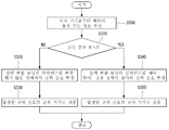
도 10은 본 발명에 따른 이동 단말기(100)에서 수행되는 배터리 고속 충전 방법의 다른 예를 나타내는 흐름도이다. 도 11은 도 10에 도시된 배터리 고속 충전 방법을 설명하기 위한 본 발명에 따른 이동 단말기(100)의 전력 픽업 유닛(210)의 블락도이다. 이하, 도 10 및 도 11등 필요한 도면들을 참조하여 상기 배터리 고속 충전 방법을 설명한다.10 is a flowchart illustrating another example of a battery fast charging method performed in the
배터리(195)에 대한 충전이 개시되면, 상기 이동 단말기(100)의 통신 및 제어 유닛(220)은 상기 배터리(195)의 충전 모드를 판단한다(S200). 배터리(195) 충전 모드가 일반 충전 모드로 판단되면(S210), 상기 통신 및 제어 유닛(220)은 정류 회로(217)의 출력 전압을 레귤레이터(219)에 인가한다(S220). 여기서, 핸드폰이나 스마트폰 등의 소형 전자 기기에서, 상기 레귤레이터(219)는 입출력단의 전압 강하가 상대적으로 낮은 LDO(Low Drop Output) 레귤레이터로 구현됨이 바람직하다. When charging of the
그러면, 상기 레귤레이터(219)는 상기 정류 회로(217)의 출력 전압에 기초하여 일정 전압을 출력하고, 충전 전압 발생 회로(222)는 상기 레귤레이터(219)의 출력 전압에 기초하여 제1 충전 전압(V1)을 발생하여 상기 배터리(195)에 인가한다(S230).Then, the
만약, 배터리(195) 충전 모드가 고속 충전 모드로 판단되면(S210), 상기 통신 및 제어 유닛(220)은 상기 정류 회로(217)의 출력 전압을 상기 충전 전압 발생 회로(222)에 바로 인가한다(S240). 그러면, 충전 전압 발생 회로(222)는 상기 정류 회로(217)의 출력 전압에 기초하여 제2 충전 전압(V2)을 발생하여 상기 배터리(195)에 인가한다(S250).If the
여기서, 상기 제2 충전 전압(V2)는 상기 제1 충전 전압(V1)보다 더 높다. 상기 정류 회로(217)의 출력 전압이 앞서 살펴본 바와 같이, 일반 충전 모드일 때보다 고속 충전 모드일 때 더 높고 레귤레이터에 의한 전압 강하 역시 배제되기 때문이다. 그러므로 고속 충전 모드에서는 보다 빠른 배터리(195) 충전이 가능할 수 있다.Here, the second charging voltage V2 is higher than the first charging voltage V1. This is because the output voltage of the
본 발명의 일 구현 형태에 따르면, 상기 충전 전압 발생 회로(222)는 상기 정류 회로(217)의 출력 전압 및 상기 레귤레이터(219)의 출력 전압에 기초하여 서로 다른 충전 전압을 발생하여 상기 배터리(195)에 인가할 수 있는 이중 입력 충전 IC(dual input charging Integrated Circuit)으로 구현될 수 있다. 본 발명의 다른 구현 형태에 따르면, 상기 전력 픽업 유닛(210)은 상기 충전 전압 발생 회로(222)에서 발생한 서로 다른 충전 전압을 이용하여 상기 배터리(195)의 충전을 제어하는 이중 입력 충전 IC를 더 포함할 수도 있다.According to the exemplary embodiment of the present invention, the charging
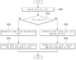
도 12는 본 발명에 따른 무선 충전 장치(300)에서 수행되는 다른 전자 기기에 포함된 배터리 고속 충전 방법의 일예를 나타내는 흐름도이다. 이하, 필요한 도면들을 참조하여 상기 배터리 고속 충전 방법을 설명한다.12 is a flowchart illustrating an example of a battery fast charging method included in another electronic device performed by the
상기 무선 충전 장치(300)는 상기 전자 기기로부터 배터리 충전 모드 정보를 무선 통신부를 통하여 수신한다(S300). 앞서 살펴본 바와 같이, 상기 전자 기기는 일반 충전 모드와 고속 충전 모드 모두를 지원하는 배터리를 포함하는 이동 단말기일 수 있다.The
배터리 충전 모드가 일반 충전 모드로 판단되면(S310), 상기 무선 충전 장치(300)의 통신 및 제어 유닛(330)은 전력 변환 유닛(320)의 임피던스를 변경하지 않은 상태에서 전력 신호를 발생한 다음(S320), 상기 발생된 전력 신호를 상기 전자 기기로 전송한다(S330). 여기서, 상기 전력 변환 유닛(320)의 임피던스를 변경하지 않는다는 것은, 일반 충전 모드로 세팅된 상기 전력 변환 유닛(320)의 설정 상태를 변경하지 않음을 의미할 수 있다.When the battery charging mode is determined as the normal charging mode (S310), the communication and
그러나, 배터리 충전 모드가 일반 충전 모드로 판단되면(S310), 상기 무선 충전 장치(300)의 통신 및 제어 유닛(330)은 전력 변환 유닛(320)의 임피던스를 제어하여 전송 전력이 증가된 전력 신호를 발생한 다음(S340), 상기 발생된 전력 신호를 상기 전자 기기로 전송한다(S350).However, when it is determined that the battery charging mode is the normal charging mode (S310), the communication and
예를 들면, 상기 통신 및 제어 유닛(330)은 상기 전력 변환 유닛(320)에 포함된 자기 유도 코일의 인덕턴스를 증가시켜 상기 자기 유도 코일에 의하여 유도되는 전압을 높임으로써 전송 전력이 증가된 전력 신호를 발생할 수 있다. 물론, 이경우에 상기 통신 및 제어 유닛(330)은 상기 자기 유도 코일의 인덕턴스 증가를 반영하여 상기 전력 변환 유닛(320)에 대한 임피던스 매칭을 수행한다.For example, the communication and
도 13은 본 발명에 따른 무선 충전 장치(300)의 전력 송신부(310)의 일예를 나타내는 블락도이다. 도 13에 도시된 상기 전력 송신부(310)의 구성요소들은 필수적인 것들이 아니다. 그러므로 본 발명의 구현 형태에 따라, 상기 전력 송신부(310)에는 도시된 것 이외의 구성요소가 포함될 수도 있으며, 도시된 구성요소가 포함되지 않을 수도 있다.13 is a block diagram illustrating an example of the
도 13을 참조하면, 상기 전력 송신부(310)는 전력 변환 유닛(320) 및 통신 및 제어 유닛(330)을 포함한다. 상기 전력 변환 유닛(320)은 입력 전압에 기초하여 외부 전자 기기의 배터리 충전용 전력 신호를 발생하며, 상기 발생된 전력 신호를 자기 유도 방식에 따라서 상기 전자 기기로 전송할 수 있다. 경우에 따라서 상기 전력 변환 유닛(320)은 상기 통신 및 제어 유닛(330)의 제어하에 상기 전자 기기와의 무선 통신을 수행하는데 이용될 수도 있다.Referring to FIG. 13, the
상기 전력 변환 유닛(320)은 인버터(322), 자기 유도 코일(321), 및 전류 센싱 유닛(323)을 포함한다. 상기 인버터(322)는 인가되는 직류 신호를 교류 신호로 변환하여 출력한다. 상기 교류 신호는 상기 자기 유도 코일(321)을 포함하는 공진 회로를 구동하는데 이용될 수 있다.The
상기 전류 센싱 유닛(323)은 상기 전력 변환 유닛(320)을 통해 흐르는 전류값을 센싱하여 상기 통신 및 제어 유닛(330)에 전달할 수 있다. 그러면, 상기 통신 및 제어 유닛(330)은 전류 센싱 결과에 기초하여 상기 전력 송신부(310)의 동작을 제어할 수 있다.The
상기 통신 및 제어 유닛(330)은 상기 전력 변환 유닛(320)을 통한 상기 전자 기기와의 무선 통신 기능을 수행할 수도 있고, 상기 전력 송신부(310)의 동작을 전반적으로 제어할 수 있다. 예를 들면, 상기 통신 및 제어 유닛(330)은, 상기 전자 기기의 배터리 충전 모드가 고속 충전 모드인 경우에는, 상기 자기 유도 코일(321)의 인덕턴스를 증가시켜 상기 전력 변환 유닛(320)에서 발생하는 전력 신호를 통하여 상기 전자 기기로 전달되는 전력을 증가시킬 수 있다. 이때, 상기 통신 및 제어 유닛(330)은 상기 자기 유도 코일(321)의 인덕턴스 증가분을 반영하여 상기 전력 변환 유닛(320)에 대한 임피던스 매칭을 수행할 수 있다.The communication and
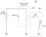
도 14는 본 발명에 따른 무선 충전 장치(300)의 전력 변환 유닛(320)의 일예를 나타내는 회로도이다. 도 14에 도시된 상기 전력 변환 유닛(320)의 구성요소들은 필수적인 것들이 아니다. 그러므로 본 발명의 구현 형태에 따라, 상기 전력 변환 유닛(320)에는 도시된 것 이외의 구성요소가 포함될 수도 있으며, 도시된 구성요소가 포함되지 않을 수도 있다.14 is a circuit diagram illustrating an example of the
도 14를 참조하면, 상기 전력 변환 유닛(320)에는 하프-브리지 인버터(half-bridge inverter, 322) 및 자기 유도 코일(321)을 포함하는 공진 회로(324)를 포함하는 것을 알 수 있다. 상기 공진 회로(324)는 상기 인버터(322)로부터 출력되는 교류 신호에 기초하여 전력 신호를 발생한 다음, 상기 발생된 전력 신호를 상기 전자 기기로 전송한다.Referring to FIG. 14, it can be seen that the
상기 공진 회로(324) 상기 자기 유도 코일(321) 및 커패시터(Cp)의 용량이 가변적이다. 이는 상기 전자 기기의 배터리 충전 모드와 관련된다. 예컨대, 통신 및 제어 유닛(330)은 상기 전자 기기의 배터리 충전 모드에 따라서 상기 자기 유도 코일(321) 및 커패시터(Cp)의 용량을 가변할 수 있다. The
보다 상세하게는, 상기 통신 및 제어 유닛(330)은 고속 충전 모드에서는 상기 자기 유도 코일(321)의 인덕턴스를 증가시켜 상기 자기 유도 코일(211)에 의하여 유도되는 전압의 크기를 증가시킴으로써 상기 전자 기기로 전송되는 전력을 증가시킬 수 있다. 증가된 송신 전력은 상기 전자 기기의 배터리의 충전 속도를 증가시키는 기초가 될 수 있다. 물론, 상기 자기 유도 코일(321)의 인덕턴스 값이 증가되면, 그에 따라 상기 커패시터(Cp)의 용량 역시 변경될 수 있다. 앞서 본 발명에 따른 이동 단말기(100)에서의 배터리 고속 충전 방법에서 살펴본 바와 유사하게, 고속 충전 모드에서 상기 자기 유도 코일(321)의 인덕턴스 값 역시 사용자의 조작 또는 상기 통신 및 제어 유닛(330)의 제어에 따라서 단계적 또는 연속적으로 증가될 수 있다.More specifically, the communication and
또한, 상기 통신 및 제어 유닛(330)은 상기 전자 기기의 배터리의 고속 충전을 구현하기 위하여 상기 커패시터(Cp)의 용량을 변경할 수도 있다. 이때, 상기 커패시터(Cp)의 변경분을 반영하여 상기 자기 유도 코일(321)의 용량 역시 변경될 수 있다.In addition, the communication and
이상에서 살펴본, 본 발명에 따른 이동 단말기(100) 또는 무선 충전 장치(300)에서의 배터리 충전 방법들 각각은 다양한 컴퓨터 수단을 통하여 수행될 수 있는 프로그램 형태로 구현되어 컴퓨터 판독 가능 매체에 기록될 수 있다. 상기 컴퓨터 판독 가능 매체는 프로그램 명령, 데이터 파일, 데이터 구조 등을 단독으로 또는 조합하여 포함할 수 있다. 상기 매체에 기록되는 프로그램은 본 발명을 위하여 특별히 설계되고 구성된 것들이거나 컴퓨터 소프트웨어 당업자에게 공지되어 사용 가능한 것일 수도 있다.As described above, each of the battery charging methods in the
컴퓨터 판독 가능 기록 매체의 예에는 하드 디스크, 플로피 디스크 및 자기 테이프와 같은 자기 매체(magnetic media), CD-ROM, DVD와 같은 광기록 매체(optical media), 플롭티컬 디스크(floptical disk)와 같은 자기-광 매체(magneto-optical media), 및 롬(ROM), 램(RAM), 플래시 메모리 등과 같은 프로그램 명령을 저장하고 수행하도록 특별히 구성된 하드웨어 장치가 포함된다. 프로그램의 예에는 컴파일러에 의해 만들어지는 것과 같은 기계어 코드뿐만 아니라 인터프리터 등을 사용해서 컴퓨터에 의해서 실행될 수 있는 고급 언어 코드를 포함한다. 상기된 하드웨어 장치는 본 발명의 동작을 수행하기 위해 하나 이상의 소프트웨어 모듈로서 작동하도록 구성될 수 있으며, 그 역도 마찬가지이다.Examples of computer-readable recording media include magnetic media such as hard disks, floppy disks, and magnetic tape, optical media such as CD-ROMs, DVDs, and magnetic disks, such as floppy disks. Magneto-optical media, and hardware devices specifically configured to store and execute program instructions, such as ROM, RAM, flash memory, and the like. Examples of programs include high-level language code that can be executed by a computer using an interpreter or the like, as well as machine code as produced by a compiler. The hardware device described above may be configured to operate as one or more software modules to perform the operations of the present invention, and vice versa.
이상과 같이 본 발명은 비록 한정된 실시예와 도면에 의해 설명되었으나, 본 발명은 상기의 실시예에 한정되는 것은 아니며, 본 발명이 속하는 분야에서 통상의 지식을 가진 자라면 이러한 기재로부터 다양한 수정 및 변형이 가능하다. As described above, the present invention has been described by way of limited embodiments and drawings, but the present invention is not limited to the above embodiments, and those skilled in the art to which the present invention pertains various modifications and variations from such descriptions. This is possible.
그러므로, 본 발명의 범위는 설명된 실시예에 국한되어 정해져서는 아니되며, 후술하는 특허청구범위뿐 아니라 이 특허청구범위와 균등한 것들에 의해 정해져야 한다.Therefore, the scope of the present invention should not be limited to the described embodiments, but should be determined not only by the claims below but also by the equivalents of the claims.
100: 이동 단말기 110: 무선 통신부
116: 입력부 120: A/V 입력부
130: 사용자 입력부 140: 센싱부
150: 출력부 151: 디스플레이부
152: 음향 출력부 160: 저장부
170: 인터페이스부 180: 제어부
190: 전원부 195: 배터리
200: 전력 수신부 210: 전력 픽업 유닛
211: 자기 유도 코일 215: 듀얼 공진 회로
216: 통신 모듈레이터 217: 정류 회로
218: 출력 차단부 219: 레귤레이터
220: 통신 및 제어 유닛 222: 충전 전압 발생 회로
300: 무선 충전 장치 305: 시스템 유닛
310: 전력 송신부 320: 전력 변환 유닛
321: 자기 유도 코일 322: 인버터
323: 전류 센싱 유닛 324: 공진 회로100: mobile terminal 110: wireless communication unit
116: input unit 120: A / V input unit
130: user input unit 140: sensing unit
150: output unit 151: display unit
152: Acoustic output unit 160:
170: interface unit 180: control unit
190: Power supply unit 195: Battery
200: power receiver 210: power pickup unit
211: magnetic induction coil 215: dual resonant circuit
216: communication modulator 217: rectifier circuit
218: output block 219: regulator
220: communication and control unit 222: charging voltage generating circuit
300: wireless charging device 305: system unit
310: power transmission unit 320: power conversion unit
321: magnetic induction coil 322: inverter
323: current sensing unit 324: resonant circuit
Claims (8)
자기 유도(magnetic induction)에 기초하여 무선 충전 장치에서 전송된 전력을 픽업하고, 상기 픽업 전력(picked-up power)에 기초하여 충전 전압을 발생하며, 상기 발생한 충전 전압을 상기 배터리에 공급하는 전력 픽업 유닛(power pick-up unit); 및
고속 충전 모드에서는, 상기 전력 픽업 유닛의 임피던스를 제어함으로써 상기 픽업 전력을 증가시키고, 상기 증가된 픽업 전력에 기초하여 상기 배터리의 충전 속도를 증가시키는 제어 유닛(control unit)을 포함하는 이동 단말기.A battery supporting a normal charging mode and a fast charging mode;
A power pickup that picks up power transmitted from the wireless charging device based on magnetic induction, generates a charging voltage based on the picked-up power, and supplies the generated charging voltage to the battery A power pick-up unit; And
In the fast charging mode, the mobile terminal including a control unit for increasing the pickup power by controlling the impedance of the power pickup unit, and increases the charging speed of the battery based on the increased pickup power.
고속 충전 모드에서는, 상기 전력 픽업 유닛에 포함된 자기 유도 코일의 인덕턴스를 증가시킴으로써 상기 픽업 전력을 증가시키는 것을 특징으로 하는 이동 단말기.The method of claim 1, wherein the control unit,
In the fast charging mode, the pickup power is increased by increasing the inductance of the magnetic induction coil included in the power pickup unit.
고속 충전 모드에서는, 상기 증가된 픽업 전력에 기초하여 상기 배터리로 공급되는 충전 전압을 증가시키는 것을 특징으로 하는 이동 단말기.3. The apparatus according to claim 2,
In the fast charging mode, the mobile terminal, characterized in that for increasing the charging voltage supplied to the battery based on the increased pickup power.
상기 자기 유도 코일에서 유도되는 교류 전압을 직류 전압으로 변환하는 정류 회로(rectification circuit);
상기 정류 회로의 출력 단자에 연결되는 레귤레이터(regulator); 및
일반 충전 모드에서는 상기 레귤레이터의 출력 전압에 기초하여 제1 충전 전압을 발생하여 상기 배터리에 공급하며, 고속 충전 모드에서는 상기 정류 회로의 출력 전압에 기초하여 제2 충전 전압을 발생하여 상기 배터리에 공급하는 충전 전압 발생 회로를 포함하는 것을 특징으로 하는 이동 단말기.The method of claim 3, wherein the power pickup unit,
A rectification circuit for converting an AC voltage induced in the magnetic induction coil into a DC voltage;
A regulator connected to the output terminal of the rectifier circuit; And
In the normal charging mode, a first charging voltage is generated and supplied to the battery based on the output voltage of the regulator. In the fast charging mode, a second charging voltage is generated and supplied to the battery based on the output voltage of the rectifier circuit. A mobile terminal comprising a charging voltage generating circuit.
고속 충전 모드에서는, 상기 무선 충전 장치에 포함된 전력 변환 유닛(power conversion unit)의 임피던스를 가변하여 상기 이동 단말기로 전송하는 전력을 증가시켜줄 것을 상기 무선 충전 장치에 요청하는 것을 특징으로 하는 이동 단말기.The mobile terminal of claim 1,
In the fast charging mode, the mobile terminal characterized in that the request for the wireless charging device to increase the power transmitted to the mobile terminal by varying the impedance of the power conversion unit (power conversion unit) included in the wireless charging device.
고속 충전 모드에서는 상기 전력 변환 유닛의 자기 유도 코일의 인덕턴스를 증가시킴으로써 상기 이동 단말기로 전송하는 전력을 증가시켜줄 것을 상기 무선 충전 장치에 요청하는 것을 특징으로 하는 이동 단말기.The method of claim 5, wherein the control unit,
And in the fast charging mode, requesting the wireless charging device to increase the power transmitted to the mobile terminal by increasing the inductance of the magnetic induction coil of the power conversion unit.
수신되는 입력 전압에 기초하여 배터리 충전용 전력 신호를 발생하고, 상기 발생한 전력 신호를 자기 유도 방식에 따라서 상기 전자 기기로 전송하는 전력 변환 유닛(power conversion unit); 및
고속 충전 모드에서는, 상기 전력 변환 유닛의 임피던스를 제어함으로써 상기 전력 신호에 기초하여 상기 전자 기기로 전송되는 전력을 증가시키는 제어 유닛(control unit)을 포함하는 무선 충전 장치.A wireless communication unit configured to receive battery charging mode information from an electronic device supporting a normal charging mode and a fast charging mode;
A power conversion unit generating a power signal for charging the battery based on the received input voltage and transmitting the generated power signal to the electronic device according to a magnetic induction method; And
In the fast charging mode, a wireless charging device including a control unit for increasing the power transmitted to the electronic device based on the power signal by controlling the impedance of the power conversion unit.
고속 충전 모드에서는, 상기 전력 변환 유닛의 자기 유도 코일의 인덕턴스를 증가시킴으로써 상기 전력 신호에 기초하여 상기 전자 기기로 전송되는 전력을 증가시키는 것을 특징으로 하는 이동 단말기.The method of claim 7, wherein the control unit,
In the fast charging mode, the mobile terminal, characterized in that to increase the power transmitted to the electronic device based on the power signal by increasing the inductance of the magnetic induction coil of the power conversion unit.
Priority Applications (3)
| Application Number | Priority Date | Filing Date | Title |
|---|---|---|---|
| KR1020120052371A KR101976176B1 (en) | 2012-05-17 | 2012-05-17 | Mobile terminal |
| US13/889,501 US20130307473A1 (en) | 2012-05-17 | 2013-05-08 | Mobile terminal |
| EP13167499.6A EP2665153B1 (en) | 2012-05-17 | 2013-05-13 | Mobile terminal |
Applications Claiming Priority (1)
| Application Number | Priority Date | Filing Date | Title |
|---|---|---|---|
| KR1020120052371A KR101976176B1 (en) | 2012-05-17 | 2012-05-17 | Mobile terminal |
Publications (2)
| Publication Number | Publication Date |
|---|---|
| KR20130128565A true KR20130128565A (en) | 2013-11-27 |
| KR101976176B1 KR101976176B1 (en) | 2019-05-08 |
Family
ID=48366223
Family Applications (1)
| Application Number | Title | Priority Date | Filing Date |
|---|---|---|---|
| KR1020120052371A KR101976176B1 (en) | 2012-05-17 | 2012-05-17 | Mobile terminal |
Country Status (3)
| Country | Link |
|---|---|
| US (1) | US20130307473A1 (en) |
| EP (1) | EP2665153B1 (en) |
| KR (1) | KR101976176B1 (en) |
Cited By (4)
| Publication number | Priority date | Publication date | Assignee | Title |
|---|---|---|---|---|
| US9825485B2 (en) | 2014-09-26 | 2017-11-21 | Samsung Electronics Co., Ltd | Wireless power transmitter and wireless power receiver |
| WO2018008963A1 (en) * | 2016-07-07 | 2018-01-11 | 삼성전자 주식회사 | Apparatus and method for altering wireless charging mode |
| US10355527B2 (en) | 2014-07-16 | 2019-07-16 | Taiwan Semiconductor Manufacturing Company Limited | Wireless charging receiver with variable resonant frequency |
| US10770637B2 (en) | 2014-11-04 | 2020-09-08 | Samsung Electronics Co., Ltd. | Energy harvester |
Families Citing this family (23)
| Publication number | Priority date | Publication date | Assignee | Title |
|---|---|---|---|---|
| WO2015015205A1 (en) * | 2013-08-01 | 2015-02-05 | The University Of Manchester | Liquid crystal device and method of manufacture |
| CN106532884B (en) | 2014-01-28 | 2019-07-19 | Oppo广东移动通信有限公司 | Battery charger and method |
| CN103762695A (en) * | 2014-02-11 | 2014-04-30 | 联想(北京)有限公司 | Electronic equipment with wireless charging function and electronic equipment with wireless charged function |
| KR102320853B1 (en) | 2014-09-02 | 2021-11-02 | 삼성전자 주식회사 | Electronic device, method for charging control of the electronic device, charging device, and method for providing power of the charging device |
| EP3216107B1 (en) | 2014-11-05 | 2022-03-02 | Hewlett-Packard Development Company, L.P. | Assisting wireless transfer of power to a machine |
| EP3220506B1 (en) * | 2014-11-11 | 2020-02-19 | Guangdong Oppo Mobile Telecommunications Corp., Ltd. | Communication method, power adaptor and terminal |
| EP4064521B1 (en) * | 2015-03-10 | 2024-05-01 | Samsung Electronics Co., Ltd. | Method and apparatus for wireless charging |
| KR102154779B1 (en) * | 2015-03-10 | 2020-09-10 | 삼성전자주식회사 | Method and apparatus for wireless charging |
| KR102514140B1 (en) * | 2015-08-12 | 2023-03-27 | 삼성전자주식회사 | Electronic device and method for controlling fan of the electronic device |
| US20170093168A1 (en) * | 2015-09-24 | 2017-03-30 | Qualcomm Incorporated | Wireless power transfer receiver having closed loop voltage control |
| US9985442B2 (en) | 2015-09-24 | 2018-05-29 | Qualcomm Incorporated | Wireless power transfer receiver having closed loop voltage control |
| DK3378238T3 (en) * | 2015-11-16 | 2023-06-12 | Sonova Ag | METHOD OF CHARGING A BATTERY IN A HEARING AID AND A HEARING AID WITH A BATTERY CHARGER |
| US10601249B2 (en) * | 2016-03-09 | 2020-03-24 | Lg Electronics Inc. | Wireless power transmitter and receiver |
| KR102572577B1 (en) * | 2016-04-15 | 2023-08-30 | 삼성전자주식회사 | Charging apparatus and method for controlling wireless charging |
| KR102534961B1 (en) * | 2016-05-04 | 2023-05-23 | 삼성전자주식회사 | Wireless power transmitter and wireless power receiver and method for operating thereof |
| CN107231013B (en) * | 2016-05-24 | 2019-01-15 | 华为技术有限公司 | A kind of method of charging, terminal, charger and system |
| CN106094967B (en) * | 2016-06-13 | 2017-08-08 | 国网上海市电力公司 | A kind of CT electricity getting devices for selecting mode of operation according to cable load and battery status |
| US10315526B2 (en) * | 2017-01-25 | 2019-06-11 | Witricity Corporation | Switched-capacitor power ramping for soft switching |
| CN111615784B (en) * | 2018-05-04 | 2023-11-21 | Oppo广东移动通信有限公司 | Step-down conversion circuit assembly and electronic equipment |
| CN110718944B (en) * | 2018-07-12 | 2023-08-04 | 中兴通讯股份有限公司 | Dual-battery charging and discharging method, device, terminal and storage medium |
| DE102019210479A1 (en) * | 2019-07-16 | 2021-01-21 | Volkswagen Aktiengesellschaft | Method for electrically charging a portable communication terminal in a motor vehicle with a charging function, as well as charging system and motor vehicle |
| DE102019210481A1 (en) * | 2019-07-16 | 2021-01-21 | Volkswagen Aktiengesellschaft | Method for electrically charging a portable communication terminal in a motor vehicle with a corresponding charging function, as well as charging system and motor vehicle |
| KR20210031335A (en) * | 2019-09-11 | 2021-03-19 | 주식회사 엘지화학 | Wireless charging receiver integrated battery management system and method |
Citations (2)
| Publication number | Priority date | Publication date | Assignee | Title |
|---|---|---|---|---|
| US20100213895A1 (en) * | 2009-02-24 | 2010-08-26 | Qualcomm Incorporated | Wireless power charging timing and charging control |
| US20110207995A1 (en) * | 2010-02-25 | 2011-08-25 | Allergan, Inc. | Inductively powered remotely adjustable gastric banding system |
Family Cites Families (11)
| Publication number | Priority date | Publication date | Assignee | Title |
|---|---|---|---|---|
| US3646439A (en) * | 1970-07-21 | 1972-02-29 | Gen Electric | Regulator with optical feedback arrangement wherein both input and output voltage are sensed |
| KR20040048005A (en) * | 2002-12-02 | 2004-06-07 | 한국전자통신연구원 | Variable impedance matching circuit |
| KR100572470B1 (en) * | 2003-09-05 | 2006-04-18 | 주식회사 팬택 | Charging mode control device of wireless communication terminal |
| KR101380748B1 (en) * | 2006-10-10 | 2014-04-02 | 삼성전자 주식회사 | Computer system and control method thereof capable of changing battery charging mode according to user's selection |
| KR101474421B1 (en) * | 2007-11-23 | 2014-12-19 | 엘지전자 주식회사 | Mobile terminal having charging menu setting function and mutual charging method using the same |
| CN103944196B (en) * | 2008-03-13 | 2017-09-22 | 捷通国际有限公司 | Induction power supply system with multiple coil primaries |
| US8374545B2 (en) * | 2009-09-02 | 2013-02-12 | Qualcomm Incorporated | De-tuning in wireless power reception |
| KR101794348B1 (en) * | 2010-10-21 | 2017-11-07 | 삼성전자주식회사 | Apparatus and method for displaying power strength and expected charged time in performing wireless charging |
| JP5804698B2 (en) * | 2010-12-10 | 2015-11-04 | キヤノン株式会社 | Power supply apparatus and method |
| US9178369B2 (en) * | 2011-01-18 | 2015-11-03 | Mojo Mobility, Inc. | Systems and methods for providing positioning freedom, and support of different voltages, protocols, and power levels in a wireless power system |
| US10332676B2 (en) * | 2011-03-24 | 2019-06-25 | Triune Systems, LLC | Coupled inductor system having multi-tap coil |
-
2012
- 2012-05-17 KR KR1020120052371A patent/KR101976176B1/en active IP Right Grant
-
2013
- 2013-05-08 US US13/889,501 patent/US20130307473A1/en not_active Abandoned
- 2013-05-13 EP EP13167499.6A patent/EP2665153B1/en not_active Not-in-force
Patent Citations (2)
| Publication number | Priority date | Publication date | Assignee | Title |
|---|---|---|---|---|
| US20100213895A1 (en) * | 2009-02-24 | 2010-08-26 | Qualcomm Incorporated | Wireless power charging timing and charging control |
| US20110207995A1 (en) * | 2010-02-25 | 2011-08-25 | Allergan, Inc. | Inductively powered remotely adjustable gastric banding system |
Cited By (6)
| Publication number | Priority date | Publication date | Assignee | Title |
|---|---|---|---|---|
| US10355527B2 (en) | 2014-07-16 | 2019-07-16 | Taiwan Semiconductor Manufacturing Company Limited | Wireless charging receiver with variable resonant frequency |
| US9825485B2 (en) | 2014-09-26 | 2017-11-21 | Samsung Electronics Co., Ltd | Wireless power transmitter and wireless power receiver |
| US10770637B2 (en) | 2014-11-04 | 2020-09-08 | Samsung Electronics Co., Ltd. | Energy harvester |
| WO2018008963A1 (en) * | 2016-07-07 | 2018-01-11 | 삼성전자 주식회사 | Apparatus and method for altering wireless charging mode |
| KR20180005853A (en) * | 2016-07-07 | 2018-01-17 | 삼성전자주식회사 | Method and Apparatus for changing Mode of Wireless Charging |
| US11063464B2 (en) | 2016-07-07 | 2021-07-13 | Samsung Electronics Co., Ltd. | Apparatus and method for altering wireless charging mode |
Also Published As
| Publication number | Publication date |
|---|---|
| KR101976176B1 (en) | 2019-05-08 |
| EP2665153A2 (en) | 2013-11-20 |
| US20130307473A1 (en) | 2013-11-21 |
| EP2665153A3 (en) | 2015-02-18 |
| EP2665153B1 (en) | 2016-06-29 |
Similar Documents
| Publication | Publication Date | Title |
|---|---|---|
| KR101976176B1 (en) | Mobile terminal | |
| EP2701277B1 (en) | Method and apparatus for wireless charging an electronic device | |
| KR101881936B1 (en) | wireless charging device and mobile terminal | |
| KR20140087628A (en) | Mobile terminal | |
| KR20150006237A (en) | Electronic device and operating method thereof | |
| KR101951473B1 (en) | Mobile terminal | |
| KR20150027614A (en) | Mobile terminal | |
| US11695301B2 (en) | Wireless charging method and device, foldable-screen electronic device and storage medium | |
| KR20140086277A (en) | Mobile communication terminal and electric aharging mobile of wireless and control method thereof | |
| KR20110004185A (en) | Mobile terminal and control method of mobile terminal | |
| KR101937480B1 (en) | Mobile terminal | |
| KR102006488B1 (en) | Mobile terminal | |
| KR102003005B1 (en) | Mobile Terminal and method of operating mobile terminal | |
| KR20140100051A (en) | Mobile terminal | |
| KR101627713B1 (en) | Mobile Terminal And Control Method Thereof | |
| KR101979841B1 (en) | Mobile terminal | |
| KR102088866B1 (en) | Mobile terminal | |
| KR101735518B1 (en) | Mobile terminal | |
| KR101659035B1 (en) | Car management system and method thereof | |
| KR20150021394A (en) | Wearable Device and Mobile Terminal Associated With Each Other | |
| KR101658567B1 (en) | Mobile terminal and control method thereof | |
| KR101948920B1 (en) | Mobile terminal | |
| KR20130042735A (en) | Electornic device | |
| KR20150040436A (en) | Electronic Device And Method Of Controlling The Same | |
| KR20120045126A (en) | Mobile terminal and operating method thereof |
Legal Events
| Date | Code | Title | Description |
|---|---|---|---|
| A201 | Request for examination | ||
| E902 | Notification of reason for refusal | ||
| E90F | Notification of reason for final refusal | ||
| E701 | Decision to grant or registration of patent right | ||
| GRNT | Written decision to grant |