KR20130126731A - Device for the automatic operation of a manual gear box - Google Patents
Device for the automatic operation of a manual gear box Download PDFInfo
- Publication number
- KR20130126731A KR20130126731A KR1020137026018A KR20137026018A KR20130126731A KR 20130126731 A KR20130126731 A KR 20130126731A KR 1020137026018 A KR1020137026018 A KR 1020137026018A KR 20137026018 A KR20137026018 A KR 20137026018A KR 20130126731 A KR20130126731 A KR 20130126731A
- Authority
- KR
- South Korea
- Prior art keywords
- shifting
- rotation
- actuating device
- axis
- slide
- Prior art date
Links
Images


Classifications
-
- F—MECHANICAL ENGINEERING; LIGHTING; HEATING; WEAPONS; BLASTING
- F16—ENGINEERING ELEMENTS AND UNITS; GENERAL MEASURES FOR PRODUCING AND MAINTAINING EFFECTIVE FUNCTIONING OF MACHINES OR INSTALLATIONS; THERMAL INSULATION IN GENERAL
- F16H—GEARING
- F16H63/00—Control outputs from the control unit to change-speed- or reversing-gearings for conveying rotary motion or to other devices than the final output mechanism
- F16H63/02—Final output mechanisms therefor; Actuating means for the final output mechanisms
- F16H63/08—Multiple final output mechanisms being moved by a single common final actuating mechanism
- F16H63/20—Multiple final output mechanisms being moved by a single common final actuating mechanism with preselection and subsequent movement of each final output mechanism by movement of the final actuating mechanism in two different ways, e.g. guided by a shift gate
-
- F—MECHANICAL ENGINEERING; LIGHTING; HEATING; WEAPONS; BLASTING
- F16—ENGINEERING ELEMENTS AND UNITS; GENERAL MEASURES FOR PRODUCING AND MAINTAINING EFFECTIVE FUNCTIONING OF MACHINES OR INSTALLATIONS; THERMAL INSULATION IN GENERAL
- F16H—GEARING
- F16H61/00—Control functions within control units of change-speed- or reversing-gearings for conveying rotary motion ; Control of exclusively fluid gearing, friction gearing, gearings with endless flexible members or other particular types of gearing
- F16H61/26—Generation or transmission of movements for final actuating mechanisms
- F16H61/28—Generation or transmission of movements for final actuating mechanisms with at least one movement of the final actuating mechanism being caused by a non-mechanical force, e.g. power-assisted
- F16H61/32—Electric motors actuators or related electrical control means therefor
-
- F—MECHANICAL ENGINEERING; LIGHTING; HEATING; WEAPONS; BLASTING
- F16—ENGINEERING ELEMENTS AND UNITS; GENERAL MEASURES FOR PRODUCING AND MAINTAINING EFFECTIVE FUNCTIONING OF MACHINES OR INSTALLATIONS; THERMAL INSULATION IN GENERAL
- F16H—GEARING
- F16H63/00—Control outputs from the control unit to change-speed- or reversing-gearings for conveying rotary motion or to other devices than the final output mechanism
- F16H63/02—Final output mechanisms therefor; Actuating means for the final output mechanisms
- F16H63/30—Constructional features of the final output mechanisms
-
- F—MECHANICAL ENGINEERING; LIGHTING; HEATING; WEAPONS; BLASTING
- F16—ENGINEERING ELEMENTS AND UNITS; GENERAL MEASURES FOR PRODUCING AND MAINTAINING EFFECTIVE FUNCTIONING OF MACHINES OR INSTALLATIONS; THERMAL INSULATION IN GENERAL
- F16H—GEARING
- F16H63/00—Control outputs from the control unit to change-speed- or reversing-gearings for conveying rotary motion or to other devices than the final output mechanism
- F16H63/02—Final output mechanisms therefor; Actuating means for the final output mechanisms
- F16H63/08—Multiple final output mechanisms being moved by a single common final actuating mechanism
- F16H63/20—Multiple final output mechanisms being moved by a single common final actuating mechanism with preselection and subsequent movement of each final output mechanism by movement of the final actuating mechanism in two different ways, e.g. guided by a shift gate
- F16H2063/208—Multiple final output mechanisms being moved by a single common final actuating mechanism with preselection and subsequent movement of each final output mechanism by movement of the final actuating mechanism in two different ways, e.g. guided by a shift gate using two or more selecting fingers
-
- F—MECHANICAL ENGINEERING; LIGHTING; HEATING; WEAPONS; BLASTING
- F16—ENGINEERING ELEMENTS AND UNITS; GENERAL MEASURES FOR PRODUCING AND MAINTAINING EFFECTIVE FUNCTIONING OF MACHINES OR INSTALLATIONS; THERMAL INSULATION IN GENERAL
- F16H—GEARING
- F16H63/00—Control outputs from the control unit to change-speed- or reversing-gearings for conveying rotary motion or to other devices than the final output mechanism
- F16H63/02—Final output mechanisms therefor; Actuating means for the final output mechanisms
- F16H63/30—Constructional features of the final output mechanisms
- F16H63/3009—Constructional features of the final output mechanisms the final output mechanisms having elements remote from the gearbox
-
- Y—GENERAL TAGGING OF NEW TECHNOLOGICAL DEVELOPMENTS; GENERAL TAGGING OF CROSS-SECTIONAL TECHNOLOGIES SPANNING OVER SEVERAL SECTIONS OF THE IPC; TECHNICAL SUBJECTS COVERED BY FORMER USPC CROSS-REFERENCE ART COLLECTIONS [XRACs] AND DIGESTS
- Y10—TECHNICAL SUBJECTS COVERED BY FORMER USPC
- Y10T—TECHNICAL SUBJECTS COVERED BY FORMER US CLASSIFICATION
- Y10T74/00—Machine element or mechanism
- Y10T74/20—Control lever and linkage systems
- Y10T74/20012—Multiple controlled elements
- Y10T74/20018—Transmission control
- Y10T74/2003—Electrical actuator
-
- Y—GENERAL TAGGING OF NEW TECHNOLOGICAL DEVELOPMENTS; GENERAL TAGGING OF CROSS-SECTIONAL TECHNOLOGIES SPANNING OVER SEVERAL SECTIONS OF THE IPC; TECHNICAL SUBJECTS COVERED BY FORMER USPC CROSS-REFERENCE ART COLLECTIONS [XRACs] AND DIGESTS
- Y10—TECHNICAL SUBJECTS COVERED BY FORMER USPC
- Y10T—TECHNICAL SUBJECTS COVERED BY FORMER US CLASSIFICATION
- Y10T74/00—Machine element or mechanism
- Y10T74/20—Control lever and linkage systems
- Y10T74/20012—Multiple controlled elements
- Y10T74/20018—Transmission control
- Y10T74/20177—Particular element [e.g., shift fork, template, etc.]
Abstract
본 발명은 자동적으로 전환되는 수동 기어박스를 위한 작동 장치에 관한 것이다. 기어박스에는 각각의 기어를 위한 이동가능한 맞물림 요소가 구비되어 있다. 작동 장치에는 회전축(1) 및 선택된 맞물림 요소를 이동시키기 위한 회전가능한 변속 핑거(2, 3, 4)가 구비되어 있다. 본 발명에 따라 변속 핑거 수단(2, 3, 4)은 특정한 맞물림 요소와 각각 결합되는 다수의 분리된 변속 핑거(2, 3, 4)를 포함하고 있다. 각각의 변속 핑거(2, 3, 4)는 다른 변속 핑거(2, 3, 4)와 무관하게 별개로 회전할 수 있도록 형성되어 있다.The present invention relates to an actuating device for a manual gearbox that is automatically switched over. The gearbox is equipped with a movable engagement element for each gear. The actuating device is equipped with rotatable shifting fingers 2, 3, 4 for moving the rotating shaft 1 and the selected engagement element. According to the invention the shifting finger means 2, 3, 4 comprise a plurality of separate shifting fingers 2, 3, 4 which are respectively engaged with a particular engagement element. Each shifting finger 2, 3, 4 is formed so as to be able to rotate separately independently of the other shifting fingers 2, 3, 4.
Description
본 발명은 자동적으로 전환되는 수동 기어박스의 작동 장치에 관한 것이며, 기어박스에는 각각의 기어를 위한 이동가능한 맞물림 요소가 구비되어 있고, 작동 장치에는 회전축 및 선택된 맞물림 요소를 이동시키기 위한 회전가능한 변속 핑거 수단이 구비되어 있다.The present invention relates to an actuating device of a manual gearbox which is automatically switched, the gearbox being provided with a movable engagement element for each gear, the actuating device being a rotatable shifting finger for moving the axis of rotation and the selected engagement element. Means are provided.
자동적으로 전환되는 수동 기어박스에서 보편적으로 나타나는 구조는 각각의 기어가 일반적으로 축의 형태인 맞물림 요소를 이동시키는 것에 의해서 맞물리거나 맞물림 해제된다는 것이다. 맞물림 요소는 변속 핑거에 의해 기어의 맞물림 또는 맞물림 해제를 위한 각각의 방향에서 노치에 맞물리고 맞물림 요소를 밀어낼 때 작동되는 요크 형상의 쇼울더 또는 노치를 가지고 있다. A common feature in manual gearboxes that are automatically switched is that each gear is engaged or disengaged by moving the engagement elements, which are generally in the form of shafts. The engagement element has a yoke shaped shoulder or notch actuated by the shifting finger to engage the notch and push the engagement element in each direction for engagement or disengagement of the gear.
변속 핑거는 회전축에 대하여 회전되는 것에 의해서 이러한 이동을 실행한다. 이것은 변속 핑거가 각각의 맞물림 축과 함께 작동하기 위한 위치로 축선방향으로 배치되도록 변속 핑거와 회전 작동 축이 먼저 축선방향으로 이동되는 것을 수반한다. The shift finger performs this movement by being rotated about an axis of rotation. This entails the shifting of the shifting finger and the rotational actuation axis first axially such that the shifting finger is positioned axially in a position for actuating with each engagement axis.
변속 핑거와 함께 회전축을 축선방향으로 이동시키는 것은 일반적으로 공압 또는 유압 동력 수단을 사용하여 상대적으로 큰 힘을 가하는 것을 내포하고 있다. 그러므로, 기어 변속은 번거롭고 부정확하게 되는 경향이 있다.Moving the axis of rotation axially with the shifting finger generally involves applying relatively large forces using pneumatic or hydraulic power means. Therefore, gear shifting tends to be cumbersome and inaccurate.
이러한 종류의 기어박스가 미국 특허 출원공개 공보 20040154419호, 미국 특허 출원공개 공보 20020189388호, 미국 특허 출원공개 공보 2001037698호 및 프랑스 특허 공보 2860567호에 기재되어 있다. Gearboxes of this kind are described in US Patent Application Publication No. 20040154419, US Patent Application Publication No. 20020189388, US Patent Application Publication No. 2001037698 and French Patent Publication No. 2860567.
미국 특허 출원공개 공보 20040154419A1호에는 기어박스에서 기어가 맞물리게 됨에 따라 변속 핑거, 조립체에서 두개 이상의 핑거를 배제시킬 수 있는, 솔레노이드 또는 전기 모터가 축 및 흡인 솔레노이드를 회전시키는 기어박스 작동을 위한 기구가 기재되어 있다. 배제시키는 것은 이중 기어 변경, 즉 두개의 셀렉터 축이 동시에 맞물리는 것을 방지한다. 배제시키는 것은 회전 운동과 축선방향 운동을 전달하는 셀렉터 축을 따라 축선방향으로 일어난다. U.S. Patent Application Publication No. 20040154419A1 describes a mechanism for gearbox operation in which a solenoid or electric motor rotates an axis and a suction solenoid, which may exclude a shifting finger, two or more fingers from the assembly as the gear is engaged in the gearbox. It is. Excluding prevents double gear changes, ie the two selector shafts meshing at the same time. Exclusion takes place axially along the selector axis, which transmits rotational and axial movement.
미국 특허 출원공개 공보 20020189388A1호에는 솔레노이드와 단지 하나의 변속 핑거에 기초하여, 7개의 상이한 위치로 변속 핑거를 전환하기 위하여 솔레노이드를 사용하는 기어 변경 기구가 기재되어 있다. 이 기구에는 전환을 실행하기 위한 3개의 솔레노이드가 있다. U.S. Patent Application Publication No. 20020189388A1 describes a gear change mechanism that uses a solenoid to shift the shift finger to seven different positions based on the solenoid and only one shift finger. This mechanism has three solenoids for carrying out the changeover.
미국 특허 출원공개 공보 2001037698호에는 솔레노이드에 의해 회전되는 변속 핑거가 기재되어 있다.U.S. Patent Application Publication No. 2001037698 describes shifting fingers rotated by solenoids.
프랑스 특허 공보 2860567호에는 다른 기어가 작동될 때 부정확한 기어가 맞물리는 것을 방지하는 잠금 슬라이드 종류의 슬라이드, 그리고 서로에 대하여 개별적으로 맞물릴 수 있는 다수의 변속 핑거가 기재되어 있다.French patent publication 2860567 describes slides of the locking slide type which prevent incorrect gears from being engaged when other gears are operated, and a number of shifting fingers which can be engaged with each other individually.
본 발명의 목적은 전술한 단점이 해소되는 작동 장치를 제공하고, 기어의 맞물림 및 맞물림 해제가 종래 기술에서 가능한 것보다 더욱 원활하고 간단하게 이루어질 수 있도록 하는 작동 장치를 제공하는 것이다. It is an object of the present invention to provide an actuating device in which the above-mentioned disadvantages are eliminated, and to provide an actuating device in which the engagement and disengagement of the gears can be made more smoothly and simply than is possible in the prior art.
전술한 목적은, 변속 핑거 수단은 다수의 분리된 변속 핑거를 포함하고 있고, 각각의 변속 핑거는 특정한 맞물림 요소(engagement element)와 결합되고 다른 변속 핑거와 무관하게 별개로 회전가능하게 되는 특징을 갖는 수동 기어박스를 자동적으로 전환하기 위한 작동 장치에 의해서 달성된다. The above object is characterized in that the shifting finger means comprise a plurality of separate shifting fingers, each shifting finger being associated with a particular engagement element and being rotatable independently of the other shifting finger. This is achieved by an actuating device for automatically switching the manual gearbox.
각각의 변속 핑거의 독립적이고 분리된 작동은 기어를 맞물림 또는 맞물림 해제하는 것과 관련하여 임의의 변속 핑거를 축선방향으로 이동시켜야 하는 필요성을 제거한다. 그러므로 원칙적으로, 변속 핑거 및 회전축은 축선방향으로 이동가능하지 않도록 변속 핑거와 회전축이 배열될 수 있다. 이것은 기어박스를 더욱 용이하게 작동시키고 정확성을 더욱 높인다. 가해지는 힘은 더욱 작아지며, 회전축의 축선 방향에서 요구되는 힘은 현저하게 감소되거나 또는 생략된다. 그러므로, 동력 장치는 단순화될 수 있고 공압 수단을 구비하지 않고 구성될 수 있다. 또한, 변속 핑거를 축선방향으로 이동시킬 수 있어야 하는 필요성을 제거함으로써 공지된 유사한 장치보다 더욱 간단하게 작동 장치를 구성할 수 있게 한다. Independent and separate operation of each shifting finger eliminates the need to move any shifting finger axially in relation to engaging or disengaging gears. Therefore, in principle, the shifting finger and the rotating shaft may be arranged such that the shifting finger and the rotating shaft are not movable in the axial direction. This makes the gearbox easier to operate and further increases accuracy. The force exerted becomes smaller and the force required in the axial direction of the axis of rotation is significantly reduced or omitted. Therefore, the power plant can be simplified and can be configured without the pneumatic means. It also eliminates the need to be able to move the shifting finger in the axial direction, making the actuating device simpler than similar devices known in the art.
양호한 일 실시예에 따르면, 변속 핑거는 다양한 작동 위치를 설정하기 위하여 축선방향으로 이동가능한 회전축을 따라 축선방향으로 차례대로 설치되는데, 각각의 작동 위치에서 회전축은 공동 회전하도록 변속 핑거들 중 오직 하나의 변속 핑거와 연결되고 회전축은 다른 변속 핑거에 대하여 회전가능하다. According to one preferred embodiment, the shifting fingers are installed one after the other in the axial direction along an axis of rotation which is axially movable in order to set various operating positions, in which the axis of rotation rotates only one of the shifting fingers to co-rotate. It is connected with the shifting finger and the rotation axis is rotatable with respect to the other shifting finger.
이것은 회전 운동을 실행하기 위한 매우 간단한 해결방안을 제공하는데, 모든 변속 핑거를 작동시키기 위해 동일한 축이 사용된다. 또한 작동 장치의 임의의 부분을 축선방향으로 이동시켜야 하는 필요성을 제거한다. This provides a very simple solution for carrying out rotational motion, in which the same axis is used to actuate all shifting fingers. It also eliminates the need to move any part of the actuating device in the axial direction.
또 다른 바람직한 실시예에 따르면, 회전축은 각각의 변속 핑거의 구멍을 통하여 뻗어 있고, 각각의 구멍은 축선방향으로 구멍을 따라 뻗어 있는 적어도 하나의 홈을 가지고 있고, 회전축에는 회전축의 작동 위치에 따라 변속 핑거의 적어도 하나에서 각각의 홈과 상호 작용하여 회전하기 위한 적어도 하나의 방사상의 돌출부가 구비되어 있다. According to another preferred embodiment, the axis of rotation extends through the holes of each shifting finger, each hole having at least one groove extending along the hole in the axial direction, and the axis of rotation is shifted according to the operating position of the axis of rotation. At least one radial protrusion is provided for rotating in interaction with each groove in at least one of the fingers.
결과적으로 회전축과 각각의 변속 핑거 사이에는 스플라인 연결이 이루어지고 따라서 효과적이고 확실한 회전 운동의 전달이 이루어진다. 회전축의 이동은 의도한 기어와 관련이 있는 변속 핑거와 상호 작용하여 회전하게 회전축의 돌출부를 집어 넣는 간단한 방식이다.As a result, a spline connection is established between the axis of rotation and each of the shifting fingers, thus providing an effective and reliable transmission of rotational motion. The movement of the axis of rotation is a simple way of interacting with the shifting finger associated with the intended gear to push the projection of the axis of rotation into rotation.
또 다른 바람직한 실시예에 따르면, 각각의 변속 핑거에는 개별적인 스프링에 의해 회전축을 향하여 눌려지는 인덱스 요소(indexing element)가 구비되어 있고, 회전축에는 인덱스 요소를 수용할 수 있는 중공부가 구비되어 있다. According to another preferred embodiment, each shifting finger is provided with an indexing element pressed against the rotational axis by an individual spring, and the rotational axis is provided with a hollow for accommodating the indexing element.
인덱스 요소는 의도한 변속 핑거를 회전시키기 위한 정확한 위치에 회전축이 도달하도록 회전축의 축선방향 위치 결정을 용이하게 한다. 인덱스 요소 중의 하나를 위한 위치로 중공부가 축선방향으로 이동될 때, 스프링은 중공부에 인덱스 요소를 스냅 결합시키며, 이에 의해 기어 변경을 위한 회전을 실행하기 위해서 변속 핑거에 대한 정확한 축선방향 위치를 나타낸다. 이 위치에서 다른 기어와 맞물림 하기 위하여 축선방향 이동할 때, 인덱스 요소는 스프링의 작용에 대항하여 노치의 밖으로 밀쳐져서 회전축의 둘레와 맞닿게 된다. The index element facilitates axial positioning of the axis of rotation such that the axis of rotation reaches the correct position for rotating the intended shifting finger. When the hollow part is moved axially to the position for one of the index elements, the spring snaps the index element to the hollow part, thereby representing the correct axial position with respect to the shifting finger in order to effect rotation for the gear change. . When moving axially to engage the other gear in this position, the index element is pushed out of the notch against the action of the spring and brought into contact with the circumference of the axis of rotation.
바람직하기로는, 인덱스 요소는 볼의 형태 또는 회전축을 향하여 마주하는 적어도 그 측면에서는 구형의 형태를 갖는 것이며, 중공부는 상응하는 구형의 형상으로 되어 있다. 따라서, 인덱스 요소의 스냅 결합 및 결합 해제가 용이하다.Preferably, the index element has a spherical shape at least on its side facing toward the shape of the ball or the axis of rotation, and the hollow portion is in the shape of a corresponding spherical shape. Thus, snap engagement and disengagement of index elements are easy.
또 다른 바람직한 실시예에 따르면, 변속 핑거는 회전축 조립체를 따라 축선방향으로 차례대로 설치되며, 회전축 조립체는 공동 회전하도록 특정한 변속 핑거에 각각 연결되고 서로에 대하여 회전가능한 다수의 동축의 회전축을 포함하고 있다. According to another preferred embodiment, the shifting fingers are installed in an axial order along the axis of rotation assembly, the axis of rotation assembly comprising a plurality of coaxial axis of rotation each connected to a particular shifting finger and rotatable relative to each other for co-rotation. .
이러한 실시예는 개별적인 변속 핑거를 견고하게 잠금하기 위한 잠금 기구를 구비하여야 하는 필요성을 배제시키는데, 이러한 점에서 단순화가 실현된다. 기어 선택은 회전축 중에서 선택된 하나를 회전시키는 것에 의해서 실행된다. This embodiment eliminates the need to have a locking mechanism for firmly locking the individual shifting fingers, in which simplification is realized. Gear selection is performed by rotating a selected one of the rotational axes.
또 다른 바람직한 실시예에 따르면, 각각의 회전축에는 공동 회전하기 위해 회전축과 연결되는 방사상으로 돌출된 피벗 요소가 구비되어 있으며, 이들 피벗 요소는 회전축 조립체를 따라 축선방향으로 차례대로 배치된다. According to another preferred embodiment, each axis of rotation is provided with radially projecting pivot elements connected to the axis of rotation for co-rotation, which are arranged in axial order along the axis of rotation assembly.
피벗 요소는 각각의 회전축의 회전을 용이하게 한다. 피벗 요소가 축선방향으로 분리되어 있다는 사실은 또한 회전축 중의 오직 하나만을 회전시키는 것을 용이하게 한다. 바람직하게, 각각의 피벗 요소는 방사상의 핀 형태이다. Pivot elements facilitate the rotation of each axis of rotation. The fact that the pivot elements are separated in the axial direction also makes it easy to rotate only one of the axes of rotation. Preferably, each pivot element is in the form of a radial pin.
또 다른 바람직한 실시예에 따르면, 본 발명의 장치는 슬라이드를 포함하고 있는데, 슬라이드는 축선방향으로 이동가능하고 회전축 조립체 상에서 회전가능하며, 슬라이드에는 슬라이드의 축선방향의 위치에 따라 선택된 피벗 요소에 대해 회전 작동하도록 되어 있는 쇼울더 요소가 구비되어 있다. According to another preferred embodiment, the device of the present invention comprises a slide, the slide being axially movable and rotatable on the rotary shaft assembly, the slide rotating about a pivot element selected according to the axial position of the slide. There is a shoulder element adapted to operate.
슬라이드와 피벗 요소는 기어의 맞물림을 위한 간단하고 견고하며 신뢰할 수 있는 기구를 구성한다. 기어 선택은 슬라이드를 이동시키는 것에 의해서 쇼율더 요소가 각각의 피벗 요소에 대해 작동하는 위치에 오도록 하는 것이다. 그 다음에 관련된 변속 핑거는 슬라이드를 회전시키는 것에 의해서 관련된 회전축을 통하여 용이하게 회전될 수 있다. The slide and pivot element constitute a simple, rigid and reliable mechanism for the gearing engagement. Gear selection is to move the slide so that the show rater element is in the working position for each pivot element. The associated shifting finger can then be easily rotated through the associated axis of rotation by rotating the slide.
또 다른 바람직한 실시예에 따르면, 슬라이드는 가장 바깥쪽의 회전축에 지지되는 절단된 원통형의 형태이며 축선방향으로 뻗어 있는 개구를 가지고 있고, 이 개구는 작은 둘레 폭을 갖는 제1 구역 및 넓은 둘레 폭을 갖는 적어도 하나의 제2 구역을 포함하고 있으며, 상기 작은 둘레 폭 및 넓은 둘레 폭은 기어를 맞물림 또는 맞물림 해제하기 위해 요구되는 변속 핑거의 이동 각도의 적어도 두배가 되는 각도 크기의 차이에 의해서 형성된다. According to another preferred embodiment, the slide is in the form of a truncated cylinder supported on the outermost axis of rotation and has an opening extending in the axial direction, the opening defining a first zone having a small circumferential width and a wide circumferential width. And at least one second zone, wherein the small circumferential width and the wide circumferential width are formed by a difference in angular magnitude that is at least twice the movement angle of the shifting finger required to engage or disengage the gear.
이와 같이 형성된 슬라이드의 쇼울더 요소는, 개구의 작은 구역의 가장자리가 그 자체로 쇼울더 요소로서의 역할을 하기 때문에 매우 간단한 구조가 될 것이다. 개구의 나머지 구역에서의 큰 폭은 다른 회전축들 그 어느 것의 피벗 요소에 영향을 주지 않으면서 슬라이드의 선회가 일어나는 것을 가능하게 한다. The shoulder element of the slide thus formed will be a very simple structure since the edge of the small section of the opening itself serves as the shoulder element. The large width in the remaining area of the opening allows the pivoting of the slide to take place without affecting the pivot element of any of the other axes of rotation.
또 다른 바람직한 실시예에 따르면, 개구는 큰 폭을 갖는 두개의 구역을 포함하고 있으며, 각각의 구역은 작은 폭을 갖는 구역의 각각의 옆에 축선방향으로 위치된다. According to another preferred embodiment, the opening comprises two zones having a large width, each zone being located axially next to each of the zones having a small width.
따라서, 기어를 맞물리기 위해 요구되는 슬라이드의 최대 축선방향 이동은 최소화된다. Thus, the maximum axial movement of the slide required to engage the gears is minimized.
바람직한 실시예에, 작은 폭은 5 - 10°범위의 각도에 해당하고 넓은 폭은 120 - 175°범위의 각도에 해당한다.In a preferred embodiment, the small width corresponds to an angle in the range 5-10 ° and the wide width corresponds to an angle in the range 120-175 °.
앞에서 언급한 작은 폭 및 넓은 폭의 상대적인 정의는 일반적으로 이와 같은 각도 범위 내에서 충족된다. 작은 폭은 적어도 각각의 피벗 요소의 둘레 크기와 같은 크기가 되어야 하며, 피벗 요소와 슬라이드 사이에 축선방향의 상대 이동의 중단을 회피하는 소정의 허용 공차를 갖는다. 전술한 범위는 이러한 점에서 바람직하다. 전술한 범위 내에서 넓은 폭은 소정의 방향에서의 기어 변경 이동을 위한 공간과 관련하여 충분한 여유를 갖게 한다. 넓은 폭이 180°미만이라는 사실은 회전축 조립체에 대하여 슬라이드를 확실하게 중심에 위치시킬 수 있도록 한다.The relative definitions of the small and wide widths mentioned above are generally satisfied within this angular range. The small width should be at least as large as the circumferential size of each pivot element and has a certain tolerance to avoid interruption of axial relative movement between the pivot element and the slide. The above-mentioned range is preferable in this respect. The wide width within the above-described range allows sufficient margin in relation to the space for the gear change movement in the predetermined direction. The fact that the wide width is less than 180 ° makes it possible to securely center the slide with respect to the axis of rotation assembly.
바람직한 실시예에, 작동 장치는 회전축 또는 회전축의 하나를 회전시키는 솔레노이드 또는 전기 모터를 포함하고 있다.In a preferred embodiment, the actuating device comprises a solenoid or electric motor which rotates one of the rotating shafts or one of the rotating shafts.
본 발명의 작동 장치는 상대적으로 작은 힘만으로도 기어를 맞물림 또는 맞물림 해제할 수 있게 한다. 이 실시예는 공압 또는 유압 작동으로 실행되는 장점을 갖는다. 본 발명의 작동 장치는 특히 간단하고 신뢰할 수 있게 된다.The actuating device of the present invention makes it possible to engage or disengage gears with only relatively small forces. This embodiment has the advantage of being implemented in pneumatic or hydraulic operation. The actuating device of the invention becomes particularly simple and reliable.
본 발명은 또한, 본 발명에 따른, 특히 본 발명의 바람직한 실시예에 따른 작동 장치를 구비한 기어박스에 관한 것이다.The invention also relates to a gearbox with an operating device according to the invention, in particular according to a preferred embodiment of the invention.
본 발명은 또한, 본 발명에 따른 기어박스를 구비한 자동차에 관한 것이다.The invention also relates to a motor vehicle with a gearbox according to the invention.
본 발명의 기어박스 및 본 발명의 자동차는, 본 발명의 작동 장치 및 작동 장치의 바람직한 실시예에 대하여 앞에서 설명한 것과 유사한 장점을 제공한다.
The gearbox of the present invention and the motor vehicle of the present invention provide advantages similar to those described above for the actuating device of the present invention and the preferred embodiment of the actuating device.
*앞에서 설명한 본 발명의 바람직한 실시예는 청구항 1을 인용하는 청구항들에 기재되어 있다. 물론, 더욱 바람직한 실시예가 전술한 바람직한 실시예의 가능한 모든 조합의 형태를 가질 수 있다는 것을 유의해야 한다.Preferred embodiments of the invention described above are described in the claims citing claim 1. Of course, it should be noted that more preferred embodiments may take the form of all possible combinations of the above-described preferred embodiments.
본 발명은 첨부 도면을 참조하여 본 발명에 따른 작동 장치의 몇가지 예로 이하에서 설명되는 상세한 설명에 의해서 더욱 상세하게 설명된다.The invention is explained in more detail by the following detailed description of several examples of operating devices according to the invention with reference to the accompanying drawings.
본 발명에 따르면, 자동적으로 전환되는 수동 기어박스의 작동 장치에서 기어의 맞물림 및 맞물림 해제가 종래 기술의 작동 장치보다 더욱 원활하고 간단하게 이루어질 수 있도록 하는 작동 장치를 제공할 수 있다.According to the present invention, it is possible to provide an operation device that allows the engagement and disengagement of gears in the operating device of the manual gearbox to be automatically switched to be made more smoothly and simply than the prior art operating device.
도 1은 본 발명의 제1 실시예에 따른 작동 장치의 측면도이다.
도 2는 도 1의 작동 장치의 일부 사시도이다.
도 3은 도 2의 작동 장치의 세부적인 단면도이다.
도 4는 제2 실시예에 따른 작동 장치의 사시도이다.
도 5는 도 4의 작동 장치의 세부적인 평면도이다.
도 6은 도 5의 라인 Ⅵ-Ⅵ을 따라 절결한 단면도이다.
도 7은 도 4의 작동 장치의 세부적인 종단면도이다.
도 8은 본 발명에 따른 작동 장치를 구비한 기어박스의 개략도이다.
도 9는 도 8에 도시된 기어박스를 구비한 차량의 개략도이다.1 is a side view of an operating device according to a first embodiment of the present invention.
2 is a partial perspective view of the actuating device of FIG. 1.
3 is a detailed cross-sectional view of the operating device of FIG. 2.
4 is a perspective view of the operating device according to the second embodiment;
5 is a detailed plan view of the operating device of FIG. 4.
6 is a cross-sectional view taken along the line VI-VI of FIG. 5.
7 is a detailed longitudinal cross-sectional view of the actuating device of FIG. 4.
8 is a schematic view of a gearbox with an operating device according to the invention.
9 is a schematic view of a vehicle with a gearbox shown in FIG. 8.
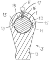
도 1에는 회전축(1)에 다수의 변속 핑거, 본 실시예에서는 3개의 변속 핑거(2, 3, 4)가 구비되어 있는 본 발명에 따른 작동 장치가 측면도로 도시되어 있다. 각각의 변속 핑거는 스플라인 연결에 의해서 회전축과 공동 회전하도록 회전축(1)에 연결가능하게 되어 있다. 변속 핑거 중의 하나가 회전축과 공동 회전하도록 회전축(1)에 견고하게 연결될 때, 다른 두개의 변속 핑거는 자유롭게 움직일 수 있다. 그러므로, 회전축(1)이 회전하면 공동 회전하도록 연결된 변속 핑거(2, 3, 4) 중의 하나가 회전하게 되는데, 이 때 도면에서 아래쪽으로 돌출한 변속 핑거의 부분은 도면에 도시된 평면에 대해 수직으로 회전할 것이다. 다른 두개의 변속 핑거는 정지되어 있게 된다. 회전되는 변속 핑거는 도면에 도시된 평면에 대해 수직으로 움직이는 도시되지 않은 맞물림 축에 연결되어 있으며 도시생략된 기어 박스에서 기어의 하나와 맞물리거나 또는 맞물림 해제하도록 맞물림 축을 이동시킨다. 1 shows a side view of the actuating device according to the invention, which is provided with a plurality of shifting fingers on the rotary shaft 1, in this embodiment three shifting
도면 부호 11은 회전축(1)을 축선방향으로 이동시키기 위한 구동 유닛이다. 바람직하게 구동 유닛(11)은 솔레노이드 또는 전기 모터이다. 도면 부호 10은 회전축을 회전시키기 위한 구동 기구를 상징적으로 나타낸 것이다. Reference numeral 11 denotes a drive unit for moving the rotating shaft 1 in the axial direction. Preferably the drive unit 11 is a solenoid or an electric motor. Reference numeral 10 symbolically represents a drive mechanism for rotating the rotating shaft.
도 2는 더욱 명확하게 나타내기 위하여 변속 핑거 중의 하나가 제거되어 있는 상태에서 사시도로 도 1의 우측 부분을 도시하고 있다. 각각의 변속 핑거(2, 3, 4)는 회전축(1)을 둘러싸는 원형부(12) 및 원형부(12)에서 돌출되어 있고 평판한 형상의 핑거부(13)를 포함하고 있다. 각각의 변속 핑거는 그 원형부에 방사상의 구멍을 가지고 있는데, 방사상의 구멍은 도 3과 관련하여 더욱 상세하게 설명되는 개별적인 인덱스 기구(5, 6, 7)를 수용한다. 회전축(1)은 두개의 돌출부(14)를 가지고 있는데, 도 2에는 단지 하나만 도시되어 있지만 다른 하나는 직경방향으로 반대쪽에 위치되어 있다. 각각의 돌출부(14)는 변속 핑거의 두께보다 약간 작은 축선방향의 크기로 축선방향으로 뻗은 산등성이 형태를 갖고 있다. FIG. 2 shows the right part of FIG. 1 in a perspective view with one of the shifting fingers removed for clarity. Each shifting
도 3은 축선방향에 대한 횡방향의 단면으로 중간의 변속 핑거(3)를 도시하고 있으며, 변속 핑거(3)는 회전축의 돌출부(14)에 대해 축선방향으로 중심에 위치되어 있다. 변속 핑거(3)는 돌출부(14)와 상응하는 형상을 갖고 직경방향으로 배치되어 있는 두개의 홈(15)을 가지고 있다. 따라서, 돌출부(14)와 서로 결합하는 홈(15)에 의해 축선방향으로 위치되는 변속 핑거(3)와 회전축(1) 사이에 스플라인 연결이 이루어진다. FIG. 3 shows an
인덱스 기구(5)는 볼 형태의 인덱스 요소(16)를 회전축 쪽으로 가압하는 스프링(17)을 포함하고 있다. 회전축(1)에는 볼(16)을 수용할 수 있는 구형의 중공부(18)가 구비되어 있다. 도시된 위치에서, 볼(16)은 중공부(19) 안으로 눌려진다. 회전축의 중공부(18)는 회전축의 돌출부(14)에 대해 축선방향으로 중심에 위치되어 있다. The index mechanism 5 comprises a
도 2 및 3을 참조하여 이하에 설명하는 바와 같이 기어 변속이 일어난다. 중립 상태에서, 변속 핑거(2, 3, 4)는 서로에 대해 중심에 위치되어 있으므로 개별적인 홈(15)은 합성된 홈을 형성한다. 이 상태에서, 회전축(1)이 위치결정되어 있으므로 돌출부(14)는 변속 핑거의 홈(15)에 대해 중심에 위치된다. 또한 회전축(1)의 중공부(18)가 변속 핑거 중의 하나, 바람직하게는 중간의 변속 핑거(3)의 볼(16)에 대해 축선방향으로 중심에 위치된다.Gear shifts occur as described below with reference to FIGS. 2 and 3. In the neutral state, the
만약 변속 핑거(4)에 의해 맞물려진 기어가 작동하게 되면, 회전축은 도 2에서 축선방향으로 우측으로 이동된다. 이에 따라 볼(16)이 중공부(18)에서 밀려나서 회전축의 둘레에서 축선방향으로 미끄럼이동을 하게 된다. 축선방향의 이동으로 인하여 중공부(18)는 도면에서 우측에 있는 변속 핑거(4)에 도달하게 되고, 변속 핑거의 볼이 중공부(18) 안으로 스냅 결합하며, 따라서 확실한 축선방향 위치가 선택된다. 이동하는 동안에, 회전축의 돌출부(14)는 우측 변속 핑거(4)의 상응하는 노치에 맞물리도록 이동한다. If the gear engaged by the shifting finger 4 is operated, the axis of rotation is moved to the right in the axial direction in FIG. Accordingly, the
이 위치에서, 회전축(1)이 회전하고, 스플라인 연결(14, 15)을 형성하여 변속 핑거(4)를 회전시키고 도시 생략된 맞물림 축에 대하여 작동시킨다. 회전 운동으로 인하여 변속 핑거(4)의 인덱스 기구(7)의 볼은 바깥으로 밀쳐지고 회전축(1)의 둘레 방향에서 미끄럼이동을 하게 된다. In this position, the rotary shaft 1 rotates, forms spline connections 14, 15 to rotate the shifting finger 4 and acts on the engagement axis, not shown. Due to the rotational movement, the ball of the index mechanism 7 of the shift finger 4 is pushed outward and is slid in the circumferential direction of the rotation shaft 1.
도시된 실시예에서 회전축은 볼 잠금을 위해 단지 하나의 중공부(18)를 가지고 있다. 대안으로, 중립 상태에서 각각의 볼(16)이 개별적인 중공부에 들어가도록 중공부의 수는 변속 핑거의 수와 동일한 것이 될 수 있다. 대안으로, 중공부 또는 중공부(18)들은 둘레 방향으로 뻗어 있는 원형 단면의 홈 형태를 가질 수 있다. In the embodiment shown, the axis of rotation has only one hollow part 18 for ball locking. Alternatively, the number of hollows can be equal to the number of shifting fingers so that each
본 발명에 따른 작동 장치의 다른 실시예가 도 4 내지 도 7에 도시되어 있다. 이 경우에, 회전축 조립체(101)가 변속 핑거(102, 103, 104)를 작동시키도록 되어 있다. 회전축 조립체(101)는 공동 회전하도록 변속 핑거(102, 103, 104)의 각각의 하나와 개별적으로 각각 연결되는 3개의 동축의 회전축(101a, 101b, 101c)으로 이루어져 있다. 따라서, 두개의 외부 회전축(101b, 101c)은 중공 축이고, 한편 내부 회전축(101a)는 중실 축이 될 수 있다. Another embodiment of the actuating device according to the invention is shown in FIGS. 4 to 7. In this case, the
회전축은 도면에서 각각의 좌측 단부에 방사상으로 돌출한 돌출 핀(105, 106, 107)을 구비하고 있으며, 각각의 핀은 중립 상태에서 모두 동일한 축선방향의 평면에 존재한다. 내부 구동축(101a)은 중간 구동축(101b)보다 좌측으로 약간 더 뻗어 있고, 중간 구동축은 가장 바깥쪽의 외부 구동축(101c) 보다 좌측으로 약간 더 뻗어 있다. 이렇게 하는 목적은 두개의 안쪽의 축에 핀(105, 106)을 위한 공간을 제공하기 위한 것이다. 회전축의 회전 운동을 실행하기 위한 슬라이드(110)가 핀의 구역에 구비된다. 회전축 조립체(101)는 도면의 우측 단부에서 제1 실시예와 유사한 방식으로 베어링 브래킷(109)에 의해 지지된 베어링 하우징(108)에 저널 결합된다. The axis of rotation has projecting
슬라이드(110)는 내경이 외부 회전축(101c)의 외경과 상응하는 전체적으로 원통 형상이며, 축선방향으로 이동 가능하고 회전될 수 있도록 외부 회전축에 저널 결합된다. 개구(111)가 슬라이드(110)의 전체 길이를 따라 축선방향으로 뻗어 있다. The
개구는 폭이 상이하며 슬라이드(110)의 길이의 각각 1/3 만큼 뻗어 있는 세개의 구역(111a, 111b, 111c)으로 분할되어 있다. 대략 반 바퀴의 각도에 해당하는 상대적으로 큰 폭의 구역(111a)이 슬라이드(110)의 한쪽 단부에 위치되어 있다. 동일한 폭의 다른 구역(111c)이 슬라이드(110)의 다른쪽 단부에 위치되어 있다. 이들 단부 사이의 슬라이드의 축선방향의 중앙 구역에는 제1 및 제2 구역보다 현저하게 작은 폭의 구역(111c)이 위치되어 있다. 중간 구역(111b)의 폭은 약 10°의 각도에 해당한다. The opening is divided into three
중간 구역은 더욱 넓은 구역(111a, 111c)을 구성하는 개구 에지의 각각의 측면에서 뻗어 있는 혀 모양의 혀형상부(115)이다. 제3 구역(111b)은 다른 두개의 구역에 대해 대칭으로 위치되어 있다. The middle zone is the tongue-shaped tongue 115 extending from each side of the opening edge which constitutes the
기어를 맞물림 및 맞물림 해제하는 것은, 가장 작은 폭을 갖는 구역(111b)이 결합할 기어와 연결되는 핀(105, 106, 107)에 대하여 축선방향으로 중심이 되도록 회전축 조립체(101)를 따라 축선방향으로 슬라이드(110)를 이동시키는 것에 의해서 실행된다. 그 다음에 슬라이드(110)가 회전되고, 이 때 가장 작은 폭의 구역(110b)의 한쪽 에지는 개별적인 핀, 도면에서의 중간 핀(106)에 대하여 눌려지고 공동 회전하게 된다. 그 결과 핀(106)이 체결된 회전축(101b)이 회전하고 따라서 회전축과 체결된 변속 핑거(103)가 회전한다. 그 다음에 변속 핑거(103)는 연결된 맞물림 축(도시 생략)을 전형적인 방식으로 이동시킨다. Engaging and disengaging gears are axially along the axis of
슬라이드(110)가 핀(106)을 이동시키기 위하여 회전할 때, 축선방향으로 위치된 개구의 구역(111a, 111c)이 현저하게 더욱 큰 폭으로 되어 있기 때문에 다른 두개의 핀(105, 107)은 영향을 받지 않게 된다. 이들 구역의 각각의 에지는 회전하는 동안 개별적인 핀에 도달하지 않게 되는데, 왜냐하면 가장 작은 폭의 구역(111b)의 에지와 다른 두개의 구역(111a, 111c)의 대응하는 에지 사이의 각도가 필요한 이동 각도보다 더 크기 때문이다. When the
가장 작은 폭의 구역이 반드시 축선방향으로 슬라이드의 중간에 위치되어야 하는 것은 아니라는 것이 이해될 수 있을 것이다. 대안으로, 슬라이드의 한쪽 단부에 위치될 수 있는데, 이 경우에 다른 두개의 구역은 더욱 큰 폭의 구역을 형성할 것이다. It will be appreciated that the smallest width zone does not necessarily have to be located in the middle of the slide in the axial direction. Alternatively, it can be located at one end of the slide, in which case the other two zones will form a larger width zone.
도면 부호 112는 슬라이드의 축선방향 이동을 위한 제어 수단을 상징적으로 나타낸 것이고, 도면 부호 113은 슬라이드에 구비된 회전 돌기(114) 중의 하나를 통하여 슬라이드를 회전시키기 위한 제어 수단을 상징적으로 나타낸 것이다. 비록 이들 제어 수단은 전형적인 공압 또는 유압 수단을 포함할 수 있지만, 본 발명에 따른 작동 장치는 이러한 목적을 위해 솔레노이드 또는 전기 모터와 같이 더욱 간단하고 비용이 저렴한 수단을 사용하는 것을 가능하게 한다. 그러므로 바람직하게, 작동 장치는 이러한 종류의 것이다.Reference numeral 112 symbolically represents a control means for axial movement of the slide, and
도 7은 각각의 연결된 작동 핑거(102, 103, 104)에 뻗어 있는 각각의 회전축(101a, 101b, 101c)을 도시하고 있는데, 작동 핑거는 회전축과 공동 회전하도록 연결되어 있다. 도면에는 또한 도면의 좌측 단부에서 축 조립체의 외측에 위치된 슬라이드(110)가 도시되어 있다. FIG. 7 shows each
도 8은 본 발명에 따른 작동 장치(200)를 구비한 기어박스(202)를 개략적으로 도시하고 있으며, 이에 의해 맞물림 축(203) 및 전환 요크(204)와 더불어 맞물림 요소(201)를 통하여 기어 변속 이동은 전형적인 방식으로 전달된다. 8 schematically shows a
도 9는 본 발명에 따른 기어박스(202)를 구비한 차량(205)을 도시하고 있다.9 shows a
1 : 회전축 2, 3, 4 : 변속 핑거
5, 6, 7, : 인덱스 기구 11 : 구동 유닛
12 : 원형부 13 : 핑거부
14 : 돌출부 15 : 홈
16 : 인덱스 요소 17 : 스프링
18, 19 : 중공부 101 : 회전축 조립체
102, 103, 104 : 변속 핑거 108 : 하우징
109 : 베어링 브라켓 110 : 슬라이드
111 : 개구 205 : 차량1:
5, 6, 7, index mechanism 11: drive unit
12: circular portion 13: finger portion
14: protrusion 15: groove
16: index element 17: spring
18, 19: hollow portion 101: rotary shaft assembly
102, 103, 104: shifting finger 108: housing
109: bearing bracket 110: slide
111: opening 205: vehicle
Claims (9)
변속 핑거(102, 103, 104)는 회전축 조립체(101)를 따라 축선방향으로 차례대로 설치되어, 회전축 조립체는 서로에 대하여 회전가능하고 공동 회전하도록 특정한 변속 핑거(102, 103, 104)와 각각 연결되는 다수의 동축의 회전축(101a, 101b, 101c)을 포함하고 있는 것을 특징으로 하는 수동 기어박스의 자동 작동 장치.An automatic actuating device of a manual gearbox which is automatically switched, the gearbox is provided with a movable engagement element for each gear, the actuating device having rotatable shifting finger means 2, 3, 4, for moving the selected engagement element. 102, 103, 104 and rotational shafts 1, 101a, 101b, 101c, each shifting finger means 2, 3, 4, 102, 103, 104 coupled with a particular engagement element, respectively, In an automatic actuating device of a manual gearbox, comprising a plurality of separate shifting fingers (2, 3, 4, 102, 103, 104) rotatable independently of the fingers,
The shifting fingers 102, 103, 104 are arranged in turn in the axial direction along the rotational shaft assembly 101, so that the rotational shaft assemblies are respectively connected to specific shifting fingers 102, 103, 104 so as to be rotatable and co-rotating with respect to each other. Automatic operation of the manual gearbox, characterized in that it comprises a plurality of coaxial rotation shaft (101a, 101b, 101c).
각각의 회전축(101a, 101b, 101c)에는 공동 회전하도록 회전축에 연결되는 방사상으로 돌출한 피벗 요소(105, 106, 107)가 구비되어 있고, 피벗 요소는 회전축 조립체(101)를 따라 축선방향으로 차례대로 배치되어 있는 것을 특징으로 하는 수동 기어박스의 자동 작동 장치.The method of claim 1,
Each axis of rotation 101a, 101b, 101c is provided with radially projecting pivot elements 105, 106, 107 connected to the axis of rotation for co-rotation, the pivot elements being axially turned along the axis of rotation assembly 101. Automatic operation device of a manual gearbox, characterized in that arranged as.
작동 장치는 축선방향으로 이동가능하고 회전축 조립체(101)에서 회전가능한 슬라이드(110)를 포함하고 있고, 상기 슬라이드에는 슬라이드(110)의 축선방향 위치에 따라 선택된 피벗 요소(105, 106, 107)에 대하여 회전 작동하는 쇼울더가 구비되어 있는 것을 특징으로 하는 수동 기어박스의 자동 작동 장치.3. The method of claim 2,
The actuating device includes a slide 110 which is axially movable and rotatable in the rotary shaft assembly 101, the slide having a pivot element 105, 106, 107 selected according to the axial position of the slide 110. Automatic operation device of a manual gearbox, characterized in that the shoulder is provided that rotates relative to.
슬라이드(110)는 가장 바깥쪽의 회전축에 저널 결합되는 절단된 원통형의 형태이며 축선방향으로 뻗은 개구(111)를 가지고 있고, 작은 둘레 폭을 갖는 제1 구역(101b) 및 큰 둘레 폭을 갖는 적어도 하나의 제2 구역(101a, 101c)을 포함하고 있으며, 상기 작은 둘레 폭과 큰 둘레 폭은 기어를 맞물리거나 또는 맞물림 해제하기 위하여 요구되는 변속 핑거(102, 103, 104)의 이동 각도의 적어도 2배가 되는 각도 차이에 의해서 형성되는 것을 특징으로 하는 수동 기어박스의 자동 작동 장치.The method of claim 3,
The slide 110 is in the form of a truncated cylindrical shape journaled to the outermost rotational axis and has an axially extending opening 111, the first zone 101b having a small circumferential width and at least a large circumferential width. One second zone 101a, 101c, wherein the small and large circumferential widths are at least two of the angles of movement of the shifting fingers 102, 103, 104 required to engage or disengage the gears. Automatic actuating device of a manual gearbox, characterized in that formed by the angular difference doubled.
개구(111)는 작은 폭 구역(101b)의 각각의 측면에 축선방향으로 각각 위치된 두개의 큰 폭 구역(101a, 101c)을 포함하고 있는 것을 특징으로 하는 수동 기어박스의 자동 작동 장치.5. The method of claim 4,
Automatic opening device of a manual gearbox, characterized in that the opening (111) comprises two large width zones (101a, 101c) positioned axially on each side of each of the small width zones (101b).
작은 폭은 5 - 10°범위의 각도에 해당하고 넓은 폭은 120 - 175°범위의 각도에 해당하는 것을 특징으로 하는 수동 기어박스의 자동 작동 장치.The method of claim 5,
Automatic operation of a manual gearbox, characterized in that the small width corresponds to an angle in the range of 5-10 ° and the wide width corresponds to an angle in the range of 120-175 °.
작동 장치는 회전축 또는 회전축 중의 하나의 회전축을 회전시키는 솔레노이드 또는 전기 모터를 포함하고 있는 것을 특징으로 하는 수동 기어박스의 자동 작동 장치.The method according to claim 6,
The actuating device is an automatic actuating device of a manual gearbox, characterized in that it comprises a solenoid or an electric motor for rotating one of the rotating shafts or one of the rotating shafts.
Applications Claiming Priority (3)
| Application Number | Priority Date | Filing Date | Title |
|---|---|---|---|
| SE0950469-7 | 2009-06-17 | ||
| SE0950469A SE533846C2 (en) | 2009-06-17 | 2009-06-17 | Control unit for a gearbox |
| PCT/SE2010/050664 WO2010147543A1 (en) | 2009-06-17 | 2010-06-14 | Device for the automatic operation of a manual gear box |
Related Parent Applications (1)
| Application Number | Title | Priority Date | Filing Date |
|---|---|---|---|
| KR1020117030105A Division KR20120024780A (en) | 2009-06-17 | 2010-06-14 | Device for the automatic operation of a manual gear box |
Publications (1)
| Publication Number | Publication Date |
|---|---|
| KR20130126731A true KR20130126731A (en) | 2013-11-20 |
Family
ID=43356617
Family Applications (2)
| Application Number | Title | Priority Date | Filing Date |
|---|---|---|---|
| KR1020137026018A KR20130126731A (en) | 2009-06-17 | 2010-06-14 | Device for the automatic operation of a manual gear box |
| KR1020117030105A KR20120024780A (en) | 2009-06-17 | 2010-06-14 | Device for the automatic operation of a manual gear box |
Family Applications After (1)
| Application Number | Title | Priority Date | Filing Date |
|---|---|---|---|
| KR1020117030105A KR20120024780A (en) | 2009-06-17 | 2010-06-14 | Device for the automatic operation of a manual gear box |
Country Status (9)
| Country | Link |
|---|---|
| US (1) | US9127767B2 (en) |
| EP (2) | EP2690323B1 (en) |
| JP (2) | JP5727470B2 (en) |
| KR (2) | KR20130126731A (en) |
| CN (2) | CN104832641A (en) |
| BR (1) | BRPI1008181A2 (en) |
| RU (1) | RU2496040C2 (en) |
| SE (1) | SE533846C2 (en) |
| WO (1) | WO2010147543A1 (en) |
Families Citing this family (14)
| Publication number | Priority date | Publication date | Assignee | Title |
|---|---|---|---|---|
| DE102008000643B4 (en) * | 2008-03-13 | 2022-02-17 | Zf Friedrichshafen Ag | Arrangement for shifting at least one loose wheel on an associated shaft of a transmission |
| SE533846C2 (en) * | 2009-06-17 | 2011-02-08 | Scania Cv Ab | Control unit for a gearbox |
| KR101249813B1 (en) * | 2012-08-31 | 2013-04-02 | 한은수 | Assembly for moving gear and transmission having the same |
| DE112014001017A5 (en) * | 2013-02-27 | 2015-11-05 | Schaeffler Technologies AG & Co. KG | Actuating device for a motor vehicle |
| DE102013004953A1 (en) * | 2013-03-22 | 2014-09-25 | Audi Ag | Actuator device for a transmission of a motor vehicle and corresponding transmission of a motor vehicle |
| CN103291901A (en) * | 2013-06-02 | 2013-09-11 | 安庆市精诚拖拉机零部件有限责任公司 | Sleeve-type compact gear shifting mechanism for tractors |
| JP6164041B2 (en) | 2013-10-22 | 2017-07-19 | スズキ株式会社 | Manual transmission shift device |
| CN104842782A (en) * | 2014-02-17 | 2015-08-19 | 张标 | Truck speed-changing connection system |
| DE102014003238A1 (en) * | 2014-03-10 | 2015-09-10 | GM Global Technology Operations LLC (n. d. Ges. d. Staates Delaware) | manual transmission |
| DE102014103523A1 (en) * | 2014-03-14 | 2015-09-17 | Getrag Getriebe- Und Zahnradfabrik Hermann Hagenmeyer Gmbh & Cie Kg | Switching arrangement for a motor vehicle transmission and switching method |
| DE102015204669A1 (en) * | 2014-04-03 | 2015-10-08 | Schaeffler Technologies AG & Co. KG | actuator assembly |
| CN104019218B (en) * | 2014-05-26 | 2016-05-11 | 西安交通大学 | A kind of variable-speed controller |
| DE102016218340A1 (en) * | 2016-09-23 | 2018-03-29 | Knorr-Bremse Systeme für Nutzfahrzeuge GmbH | Aisle and lanes (XY) gearbox |
| KR101943739B1 (en) * | 2017-06-22 | 2019-01-30 | 현대트랜시스 주식회사 | Shift Apparatus For Manual Transmission |
Family Cites Families (35)
| Publication number | Priority date | Publication date | Assignee | Title |
|---|---|---|---|---|
| US2922315A (en) | 1957-11-29 | 1960-01-26 | Gen Motors Corp | Transmission control |
| US3242759A (en) * | 1963-06-28 | 1966-03-29 | Zahnradfabrik Friedrichshafen | Shifting arrangement for change speed gears of motor vehicles |
| JPS484804U (en) * | 1971-05-21 | 1973-01-20 | ||
| JPS5127767B2 (en) | 1973-05-02 | 1976-08-14 | ||
| JPS5424211Y2 (en) | 1974-08-22 | 1979-08-16 | ||
| DE3136923C1 (en) | 1981-09-17 | 1983-01-27 | Daimler-Benz Ag, 7000 Stuttgart | Manual shift device for 5-gear transmission for motor vehicles |
| DE3432400A1 (en) * | 1983-09-13 | 1985-03-21 | Zahnradfabrik Friedrichshafen Ag, 7990 Friedrichshafen | Detent in a gear-shift device |
| JPS6165517A (en) | 1984-08-29 | 1986-04-04 | ゴーレム ラブス | Digital signal filtering device and method |
| JPS6313548Y2 (en) * | 1984-09-28 | 1988-04-18 | ||
| CS258206B1 (en) * | 1986-02-24 | 1988-07-15 | Vladimir Vaclavik | Device for gear shifting and blocking |
| JPS6380356A (en) | 1986-09-24 | 1988-04-11 | Seiko Instr & Electronics Ltd | Electronic reminder |
| JPS6380356U (en) * | 1986-11-13 | 1988-05-27 | ||
| DE3841780A1 (en) * | 1988-12-12 | 1990-08-23 | Porsche Ag | ACTUATING DEVICE FOR A GEARBOX |
| DE19539599C2 (en) * | 1995-10-25 | 1997-08-14 | Ford Werke Ag | Switching device for motor vehicle change gearbox with braking of the input shaft when switching on the reverse gear |
| ATE202665T1 (en) * | 1998-12-29 | 2001-07-15 | Swisscom Mobile Ag | METHOD AND SYSTEM FOR PROVIDING OBJECTS TO USERS OF A TELECOMMUNICATIONS NETWORK |
| JP2001304406A (en) | 2000-04-27 | 2001-10-31 | Isuzu Motors Ltd | Shift assist device for transmission |
| JP2002089707A (en) | 2000-09-18 | 2002-03-27 | Aisin Ai Co Ltd | Select mechanism of automatic shift manual transmission |
| DE10108881B4 (en) | 2001-02-23 | 2013-05-29 | Volkswagen Ag | Double-clutch transmission and method for shift control of a dual-clutch transmission |
| GB2389880B (en) * | 2001-02-23 | 2005-06-01 | Luk Lamellen & Kupplungsbau | Transmission |
| JP4211244B2 (en) * | 2001-06-18 | 2009-01-21 | いすゞ自動車株式会社 | Shifting operation device |
| DE10142225A1 (en) * | 2001-08-29 | 2003-03-20 | Zahnradfabrik Friedrichshafen | Single-rod switching device for motor vehicle manual transmissions |
| DE10253471A1 (en) * | 2002-11-16 | 2004-08-26 | Zf Friedrichshafen Ag | Gear shift device |
| GB0226934D0 (en) * | 2002-11-19 | 2002-12-24 | Luk Lamellen & Kupplungsbau | Gear engagement mechanism |
| FR2860567B1 (en) | 2003-10-03 | 2006-12-01 | Renault Sa | DEVICE AND METHOD FOR INTERNALLY CONTROLLING AN AUTOMATED GEARBOX |
| FR2863028B1 (en) | 2003-11-27 | 2006-02-24 | Peugeot Citroen Automobiles Sa | DEVICE FOR SELECTING AND TRANSFERRING SPEEDS FOR A PILOT BOX. |
| US8635925B2 (en) * | 2004-11-22 | 2014-01-28 | Eaton Corporation | Transmission auxiliary unit shift inhibitor |
| ITTO20050245A1 (en) | 2005-04-13 | 2006-10-14 | Skf Ab | CONTROL UNIT FOR A CHANGE OF A MOTOR VEHICLE. |
| DE102005058406B4 (en) | 2005-12-07 | 2010-06-17 | Dr. Ing. H.C. F. Porsche Aktiengesellschaft | Actuating device for a manual transmission |
| DE102006054611A1 (en) * | 2006-11-17 | 2008-05-21 | Dr.Ing.H.C. F. Porsche Ag | Actuation device for e.g. double clutch transmission, has shaft holding shift fingers that are mounted in shaft in axially non-movable manner, where shaft is provided with passage holes for holding balls |
| ITTV20060007A1 (en) * | 2006-01-24 | 2007-07-25 | Nice Spa | BRAKE CLUTCH DEVICE |
| DE602006001359D1 (en) * | 2006-03-02 | 2008-07-10 | Elasis Societa Consortile Per | Switching device for a vehicle transmission |
| JP4235845B2 (en) * | 2007-06-11 | 2009-03-11 | 三菱自動車工業株式会社 | Transmission |
| JP4235847B2 (en) | 2007-08-09 | 2009-03-11 | 三菱自動車工業株式会社 | Transmission |
| EP2143979B1 (en) * | 2008-05-13 | 2012-02-08 | Magneti Marelli S.p.A. | Double-clutch gearchange |
| SE533846C2 (en) * | 2009-06-17 | 2011-02-08 | Scania Cv Ab | Control unit for a gearbox |
-
2009
- 2009-06-17 SE SE0950469A patent/SE533846C2/en not_active IP Right Cessation
-
2010
- 2010-06-14 US US13/378,104 patent/US9127767B2/en not_active Expired - Fee Related
- 2010-06-14 RU RU2012101346/11A patent/RU2496040C2/en not_active IP Right Cessation
- 2010-06-14 CN CN201510136843.9A patent/CN104832641A/en active Pending
- 2010-06-14 KR KR1020137026018A patent/KR20130126731A/en not_active Application Discontinuation
- 2010-06-14 KR KR1020117030105A patent/KR20120024780A/en active Search and Examination
- 2010-06-14 CN CN2010800264442A patent/CN102803798A/en active Pending
- 2010-06-14 JP JP2012516033A patent/JP5727470B2/en not_active Expired - Fee Related
- 2010-06-14 BR BRPI1008181A patent/BRPI1008181A2/en not_active IP Right Cessation
- 2010-06-14 EP EP13190013.6A patent/EP2690323B1/en active Active
- 2010-06-14 EP EP10789821A patent/EP2443368A4/en not_active Withdrawn
- 2010-06-14 WO PCT/SE2010/050664 patent/WO2010147543A1/en active Application Filing
-
2013
- 2013-10-18 JP JP2013217428A patent/JP5726979B2/en not_active Expired - Fee Related
Also Published As
| Publication number | Publication date |
|---|---|
| JP5726979B2 (en) | 2015-06-03 |
| EP2690323A1 (en) | 2014-01-29 |
| SE533846C2 (en) | 2011-02-08 |
| CN104832641A (en) | 2015-08-12 |
| US9127767B2 (en) | 2015-09-08 |
| JP2014040923A (en) | 2014-03-06 |
| JP2012530881A (en) | 2012-12-06 |
| US20120090421A1 (en) | 2012-04-19 |
| RU2496040C2 (en) | 2013-10-20 |
| EP2443368A4 (en) | 2012-11-21 |
| KR20120024780A (en) | 2012-03-14 |
| SE0950469A1 (en) | 2010-12-18 |
| RU2012101346A (en) | 2013-09-10 |
| CN102803798A (en) | 2012-11-28 |
| BRPI1008181A2 (en) | 2016-03-01 |
| EP2690323B1 (en) | 2019-08-14 |
| WO2010147543A1 (en) | 2010-12-23 |
| EP2443368A1 (en) | 2012-04-25 |
| JP5727470B2 (en) | 2015-06-03 |
Similar Documents
| Publication | Publication Date | Title |
|---|---|---|
| KR20130126731A (en) | Device for the automatic operation of a manual gear box | |
| US8505403B2 (en) | Gear shifting actuator and method of shifting gear ratios | |
| CN106170636A (en) | Axial action actuator for multi-mode clutch module | |
| EP1830092B1 (en) | Device for synchronization and engagement of a gear change of a motor vehicle | |
| RU2293227C2 (en) | Device for assembling synchronizing members in gear box | |
| EP1156240B1 (en) | Electric drive device for transmission | |
| US8726752B2 (en) | Shift securing device for a multi-speed manual gearbox | |
| JPH05203052A (en) | Range changeover device of car transmission | |
| KR101603795B1 (en) | Shifting Apparatus for Dual Clutch Transmission | |
| KR101628104B1 (en) | Shifting apparatus for vehicle | |
| GB2325714A (en) | Device for operating a selector shaft of a shift transmission | |
| US8151664B2 (en) | Transmission unit provided with a control device for a motor vehicle | |
| JP2000240791A (en) | Gear shift mechanism of transmission | |
| JP2002317871A (en) | Electric driving device for transmission | |
| JP4587066B2 (en) | transmission | |
| KR20170003174A (en) | A device for transmitting gears | |
| JP2016142276A (en) | Shift device for automatic transmission | |
| JP2000179688A (en) | Transmission operating mechanism of transmission | |
| KR101181135B1 (en) | Clutch Actuating Apparatus for Double Clutch Transmission | |
| JP2011052740A (en) | Shift device and transmission equipped therewith | |
| KR20050122704A (en) | Shifting control apparatus for manual transmission |
Legal Events
| Date | Code | Title | Description |
|---|---|---|---|
| A107 | Divisional application of patent | ||
| WITN | Application deemed withdrawn, e.g. because no request for examination was filed or no examination fee was paid |