KR20130112367A - Electric parking brake system - Google Patents
Electric parking brake system Download PDFInfo
- Publication number
- KR20130112367A KR20130112367A KR1020120034681A KR20120034681A KR20130112367A KR 20130112367 A KR20130112367 A KR 20130112367A KR 1020120034681 A KR1020120034681 A KR 1020120034681A KR 20120034681 A KR20120034681 A KR 20120034681A KR 20130112367 A KR20130112367 A KR 20130112367A
- Authority
- KR
- South Korea
- Prior art keywords
- parking brake
- lever
- shaft
- motor
- rotation
- Prior art date
Links
Images


Classifications
-
- B—PERFORMING OPERATIONS; TRANSPORTING
- B60—VEHICLES IN GENERAL
- B60L—PROPULSION OF ELECTRICALLY-PROPELLED VEHICLES; SUPPLYING ELECTRIC POWER FOR AUXILIARY EQUIPMENT OF ELECTRICALLY-PROPELLED VEHICLES; ELECTRODYNAMIC BRAKE SYSTEMS FOR VEHICLES IN GENERAL; MAGNETIC SUSPENSION OR LEVITATION FOR VEHICLES; MONITORING OPERATING VARIABLES OF ELECTRICALLY-PROPELLED VEHICLES; ELECTRIC SAFETY DEVICES FOR ELECTRICALLY-PROPELLED VEHICLES
- B60L7/00—Electrodynamic brake systems for vehicles in general
- B60L7/24—Electrodynamic brake systems for vehicles in general with additional mechanical or electromagnetic braking
-
- B—PERFORMING OPERATIONS; TRANSPORTING
- B60—VEHICLES IN GENERAL
- B60T—VEHICLE BRAKE CONTROL SYSTEMS OR PARTS THEREOF; BRAKE CONTROL SYSTEMS OR PARTS THEREOF, IN GENERAL; ARRANGEMENT OF BRAKING ELEMENTS ON VEHICLES IN GENERAL; PORTABLE DEVICES FOR PREVENTING UNWANTED MOVEMENT OF VEHICLES; VEHICLE MODIFICATIONS TO FACILITATE COOLING OF BRAKES
- B60T13/00—Transmitting braking action from initiating means to ultimate brake actuator with power assistance or drive; Brake systems incorporating such transmitting means, e.g. air-pressure brake systems
- B60T13/74—Transmitting braking action from initiating means to ultimate brake actuator with power assistance or drive; Brake systems incorporating such transmitting means, e.g. air-pressure brake systems with electrical assistance or drive
- B60T13/746—Transmitting braking action from initiating means to ultimate brake actuator with power assistance or drive; Brake systems incorporating such transmitting means, e.g. air-pressure brake systems with electrical assistance or drive and mechanical transmission of the braking action
-
- F—MECHANICAL ENGINEERING; LIGHTING; HEATING; WEAPONS; BLASTING
- F16—ENGINEERING ELEMENTS AND UNITS; GENERAL MEASURES FOR PRODUCING AND MAINTAINING EFFECTIVE FUNCTIONING OF MACHINES OR INSTALLATIONS; THERMAL INSULATION IN GENERAL
- F16D—COUPLINGS FOR TRANSMITTING ROTATION; CLUTCHES; BRAKES
- F16D65/00—Parts or details
- F16D65/14—Actuating mechanisms for brakes; Means for initiating operation at a predetermined position
- F16D65/16—Actuating mechanisms for brakes; Means for initiating operation at a predetermined position arranged in or on the brake
- F16D65/18—Actuating mechanisms for brakes; Means for initiating operation at a predetermined position arranged in or on the brake adapted for drawing members together, e.g. for disc brakes
-
- F—MECHANICAL ENGINEERING; LIGHTING; HEATING; WEAPONS; BLASTING
- F16—ENGINEERING ELEMENTS AND UNITS; GENERAL MEASURES FOR PRODUCING AND MAINTAINING EFFECTIVE FUNCTIONING OF MACHINES OR INSTALLATIONS; THERMAL INSULATION IN GENERAL
- F16D—COUPLINGS FOR TRANSMITTING ROTATION; CLUTCHES; BRAKES
- F16D2121/00—Type of actuator operation force
- F16D2121/18—Electric or magnetic
- F16D2121/24—Electric or magnetic using motors
Landscapes
- Engineering & Computer Science (AREA)
- Mechanical Engineering (AREA)
- Transportation (AREA)
- General Engineering & Computer Science (AREA)
- Physics & Mathematics (AREA)
- Electromagnetism (AREA)
- Power Engineering (AREA)
- Braking Arrangements (AREA)
Abstract
Description
The present invention relates to a parking brake device mounted on a vehicle, and more particularly to an electric parking brake device operated by a motor.
In general, the parking brake device is a device for stopping the vehicle from moving when the vehicle is parked, and serves to hold the wheel of the vehicle against rotation.
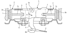
1 is a cross-sectional view showing a partial configuration of a vehicle equipped with a conventional manual parking brake device.
Referring to the drawings, a first brake shoe having a
The first and
The actuating
Rotating lever (8) is one end is rotatably coupled to the support lever (6) through the rotating shaft (8a), the other end extends through the
In addition, a portion where the other end of the
Such a parking brake device includes a
Meanwhile, reference numeral '9', which is not described, is a return spring for returning the two
In the conventional parking brake device, the rotation lever 8 rotates when the
However, such a conventional manual parking brake device has the inconvenience that the driver should pull the parking lever with an appropriate force, the operation radius of the parking lever is large, there is a problem that the utilization of the interior space of the vehicle is inferior.
In order to solve the various disadvantages of the manual parking brake, an electric parking brake that automatically operates the brake using a motor has been proposed, which improves the usability of the installation space, the compactness of the structure, and the improvement of the operating performance. Various research and development are being done to.
The present invention has been made in view of the above technical background, and the connection between the structure and components of each component, such as a motor for generating a driving force, a gear for transmitting the driving force, and a screw-nut member for converting the rotational movement into a linear movement. The purpose of the present invention is to provide an electric parking brake device that can be used more smoothly and stably by improving the structure, and that the parts of the existing parking brake device can be used in common with little or no change.
In order to achieve the above object, the motorized parking brake apparatus according to an aspect of the present invention, a drum that rotates with the wheel of the vehicle, the first and second brakes respectively installed on both sides of the drum for braking the drum A parking brake device comprising a shoe, an actuating lever supporting two brake shoes and pushing the two brake shoes to an inner surface of a drum when the pivoting lever is pulled, the motor generating a driving force for driving the pivoting lever; A cycloid reducer connected to the rotation shaft of the motor to amplify the driving force; A spindle member connected to the cycloid reducer and rotating to form a male thread; And a nut member having a female screw portion that is screwed to allow a linear movement to the male screw portion of the spindle member. The nut member is provided with a lever pin fitted to and engaged with a ring portion formed at an end of the pivot lever.
In addition, the cycloid reducer, the eccentric rotation unit is coupled to the rotary shaft of the motor to transfer the rotation eccentrically; A cycloid gear provided at the center of the eccentric rotation part and having a plurality of through holes radially from the center thereof and eccentrically rotating by the eccentric rotation part; An internal gear formed in engagement with an outer surface of the cycloid gear and allowing the cycloid gear to revolve and rotate by rotation of the rotary shaft; And an output shaft inserted into a plurality of through holes, respectively, to compensate for the eccentric center of the cycloidal gear.
In addition, the internal gear may be fixed to the motor to prevent rotation.
In addition, a bearing may be installed between the cycloid gear and the eccentric rotation part.
The spindle member may further include a spindle shaft having a predetermined length and having a male screw portion formed on an outer circumferential surface thereof; And a flange portion protruding radially from the other end portion of the spindle shaft, wherein the flange portion has a coupling hole formed at a position corresponding to the through hole, and coupled to the output shaft.
In addition, at one end of the spindle shaft may be provided with a polygonal connecting shaft protruding outward from the portion of the male screw formed to rotate the spindle shaft manually from the outside.
The electric parking brake apparatus according to the present invention can be conveniently used by braking using a motor, as well as to reduce the space of the conventional parking lever provided in the driver's seat can improve the space utilization. That is, the assembly of the vehicle can be improved by eliminating the conventional parking cable.
In addition, by using the cycloid reducer, high deceleration is possible, as well as by combining the motor and the cycloid reducer and the spindle member in series to minimize the overall length can provide a compact coupling structure and improve the space utilization.
In addition, by directly installing and using the conventional parking brake device, there is an effect that the existing vehicle parts can be applied with almost no modification.
BRIEF DESCRIPTION OF THE DRAWINGS The present invention will be described in detail with reference to the following drawings, which illustrate preferred embodiments of the present invention, and thus the technical idea of the present invention should not be construed as being limited thereto.
1 is a cross-sectional view schematically showing the configuration of a conventional parking brake device.
2 is a cross-sectional view schematically showing the configuration of an electric parking brake apparatus according to a preferred embodiment of the present invention.
3 is an exploded perspective view showing an actuator provided in the electric parking brake apparatus according to the preferred embodiment of the present invention.
4 is a cross-sectional view showing a braking state of the electric parking brake apparatus according to the preferred embodiment of the present invention.
Hereinafter, preferred embodiments of the present invention will be described in detail with reference to the accompanying drawings. Prior to this, terms or words used in the specification and claims should not be construed as having a conventional or dictionary meaning, and the inventors should properly explain the concept of terms in order to best explain their own invention. Based on the principle that can be defined, it should be interpreted as meaning and concept corresponding to the technical idea of the present invention. Therefore, the embodiments described in this specification and the configurations shown in the drawings are merely the most preferred embodiments of the present invention and do not represent all the technical ideas of the present invention. Therefore, It is to be understood that equivalents and modifications are possible.
2 is a cross-sectional view schematically showing the configuration of an electric parking brake apparatus according to a preferred embodiment of the present invention. Here, the same reference numerals as in the drawings of the conventional parking brake apparatus described above refer to members having the same function.
As shown in FIG. 2, the electric
In the electric
As described above, the actuator unit includes a
Referring to the drawings, the
On the other hand, the
The
The
The
The
The
The
One end of the
When the
For example, when the
That is, since the amount of rotation of the
According to the present invention, by adopting the structure of the
The
The
The connecting
The
The nut member 140 moves along the longitudinal direction of the
Then, the braking operation of the electric parking brake device as described above will be described.
As shown in FIG. 2, the driver of the vehicle in a state in which the two
Here, the
On the other hand, when the braking force is released, the nut member 140 is moved to its original position as the
The electric
While the present invention has been particularly shown and described with reference to exemplary embodiments thereof, it is to be understood that the invention is not limited to the disclosed exemplary embodiments. It will be understood that various modifications and changes may be made without departing from the scope of the appended claims.
100: electric parking brake device 110: motor
111: rotating shaft 120: cycloidal reducer
121: eccentric rotation part 122: bearing
123: cycloidal gear 125: internal gear
126: output shaft 130: spindle member
131: spindle shaft 132: connecting shaft
133: flange 140: nut member
148: lever pin
Claims (6)
A motor generating a driving force for driving the pivot lever;
A cycloid reducer connected to the rotation shaft of the motor to amplify the driving force;
A spindle member connected to the cycloid reducer and rotating to form a male thread; And
And a nut member having a female screw portion that is screwed to allow a linear movement to the male screw portion of the spindle member.
The nut member is an electric parking brake device, characterized in that the lever pin is fitted is coupled to the ring portion formed at the end of the rotation lever.
The cycloid reducer,
An eccentric rotation unit which is coupled to the rotation shaft of the motor to transmit the rotation eccentrically;
A cycloid gear provided at the center of the eccentric rotation part and having a plurality of through holes radially from the center thereof and eccentrically rotating by the eccentric rotation part;
An internal gear formed in engagement with an outer surface of the cycloid gear and allowing the cycloid gear to revolve and rotate by rotation of the rotary shaft; And
And an output shaft inserted into each of the plurality of through-holes to compensate for the eccentric center of the cycloidal gear.
The internal gear of the electric parking brake, characterized in that fixed to the motor to prevent rotation.
Electric parking brake device characterized in that the bearing is installed between the cycloid gear and the eccentric rotation.
The spindle member,
A spindle shaft having a predetermined length and having an external thread formed on an outer circumferential surface thereof; And
And a flange portion protruding radially from the other end portion of the spindle shaft,
The flange portion is an electric parking brake device characterized in that the coupling hole is formed in a position corresponding to the through hole is coupled to the output shaft.
One end of the spindle shaft is an electric parking brake device, characterized in that the connection shaft is formed in a polygonal shape projecting outward from the portion formed with a male screw portion to rotate the spindle shaft manually from the outside.
Priority Applications (1)
| Application Number | Priority Date | Filing Date | Title |
|---|---|---|---|
| KR1020120034681A KR20130112367A (en) | 2012-04-04 | 2012-04-04 | Electric parking brake system |
Applications Claiming Priority (1)
| Application Number | Priority Date | Filing Date | Title |
|---|---|---|---|
| KR1020120034681A KR20130112367A (en) | 2012-04-04 | 2012-04-04 | Electric parking brake system |
Publications (1)
| Publication Number | Publication Date |
|---|---|
| KR20130112367A true KR20130112367A (en) | 2013-10-14 |
Family
ID=49633378
Family Applications (1)
| Application Number | Title | Priority Date | Filing Date |
|---|---|---|---|
| KR1020120034681A KR20130112367A (en) | 2012-04-04 | 2012-04-04 | Electric parking brake system |
Country Status (1)
| Country | Link |
|---|---|
| KR (1) | KR20130112367A (en) |
Cited By (3)
| Publication number | Priority date | Publication date | Assignee | Title |
|---|---|---|---|---|
| KR20160121084A (en) * | 2015-04-10 | 2016-10-19 | 현대모비스 주식회사 | Electronic parking brake |
| KR20180020426A (en) * | 2016-08-18 | 2018-02-28 | 주식회사 만도 | Apparatus for parking brake |
| CN113631835A (en) * | 2019-01-31 | 2021-11-09 | 多重齿轮有限公司 | Transmission device |
-
2012
- 2012-04-04 KR KR1020120034681A patent/KR20130112367A/en not_active Application Discontinuation
Cited By (4)
| Publication number | Priority date | Publication date | Assignee | Title |
|---|---|---|---|---|
| KR20160121084A (en) * | 2015-04-10 | 2016-10-19 | 현대모비스 주식회사 | Electronic parking brake |
| KR20180020426A (en) * | 2016-08-18 | 2018-02-28 | 주식회사 만도 | Apparatus for parking brake |
| CN113631835A (en) * | 2019-01-31 | 2021-11-09 | 多重齿轮有限公司 | Transmission device |
| CN113631835B (en) * | 2019-01-31 | 2024-05-24 | 多重齿轮有限公司 | Transmission device |
Similar Documents
| Publication | Publication Date | Title |
|---|---|---|
| KR20130037875A (en) | Electronic parking brake | |
| JP4359294B2 (en) | Electric parking brake device | |
| KR101250830B1 (en) | Electric parking brake system | |
| US8292042B2 (en) | Electric disk brake | |
| KR20070033627A (en) | Disc brake with parking function | |
| KR20150068566A (en) | Electronic parking brake | |
| JP4611363B2 (en) | Single-motor electronic wedge brake system with fixed parking braking force | |
| US20130087417A1 (en) | Electronic disc brake | |
| KR20130117091A (en) | Electronic parking brake | |
| US8408367B2 (en) | Drum brake | |
| KR20150062441A (en) | Electronic parking brake | |
| US20150362032A1 (en) | Electronic parking brake | |
| JP4496515B2 (en) | Electric brake device | |
| US8151947B2 (en) | Single motor electronic controlled wedge brake system | |
| JP5614528B2 (en) | Disc brake | |
| JP5456164B2 (en) | Brake booster | |
| KR20130112367A (en) | Electric parking brake system | |
| JP2016050629A (en) | Gear unit and brake device | |
| US11932214B2 (en) | Parking actuator and electromechanical brake including the same | |
| KR101227045B1 (en) | Electric parking brake system | |
| US9566956B2 (en) | Electric parking brake device | |
| KR20130109557A (en) | Electronic parking brake | |
| US20230061860A1 (en) | Electric parking brake and vehicle having the same | |
| KR20060134440A (en) | Electric parking brake system | |
| KR20150072582A (en) | Power transmitting device for electric parking brake system |
Legal Events
| Date | Code | Title | Description |
|---|---|---|---|
| A201 | Request for examination | ||
| E902 | Notification of reason for refusal | ||
| E601 | Decision to refuse application |