KR20130108381A - Thermoelectric modules for exhaust system - Google Patents
Thermoelectric modules for exhaust system Download PDFInfo
- Publication number
- KR20130108381A KR20130108381A KR1020137011384A KR20137011384A KR20130108381A KR 20130108381 A KR20130108381 A KR 20130108381A KR 1020137011384 A KR1020137011384 A KR 1020137011384A KR 20137011384 A KR20137011384 A KR 20137011384A KR 20130108381 A KR20130108381 A KR 20130108381A
- Authority
- KR
- South Korea
- Prior art keywords
- thermoelectric module
- heat exchanger
- micro heat
- thermoelectric
- internal combustion
- Prior art date
Links
Images
Classifications
-
- H—ELECTRICITY
- H10—SEMICONDUCTOR DEVICES; ELECTRIC SOLID-STATE DEVICES NOT OTHERWISE PROVIDED FOR
- H10N—ELECTRIC SOLID-STATE DEVICES NOT OTHERWISE PROVIDED FOR
- H10N10/00—Thermoelectric devices comprising a junction of dissimilar materials, i.e. devices exhibiting Seebeck or Peltier effects
-
- F—MECHANICAL ENGINEERING; LIGHTING; HEATING; WEAPONS; BLASTING
- F01—MACHINES OR ENGINES IN GENERAL; ENGINE PLANTS IN GENERAL; STEAM ENGINES
- F01N—GAS-FLOW SILENCERS OR EXHAUST APPARATUS FOR MACHINES OR ENGINES IN GENERAL; GAS-FLOW SILENCERS OR EXHAUST APPARATUS FOR INTERNAL COMBUSTION ENGINES
- F01N5/00—Exhaust or silencing apparatus combined or associated with devices profiting from exhaust energy
- F01N5/02—Exhaust or silencing apparatus combined or associated with devices profiting from exhaust energy the devices using heat
- F01N5/025—Exhaust or silencing apparatus combined or associated with devices profiting from exhaust energy the devices using heat the device being thermoelectric generators
-
- H—ELECTRICITY
- H10—SEMICONDUCTOR DEVICES; ELECTRIC SOLID-STATE DEVICES NOT OTHERWISE PROVIDED FOR
- H10N—ELECTRIC SOLID-STATE DEVICES NOT OTHERWISE PROVIDED FOR
- H10N10/00—Thermoelectric devices comprising a junction of dissimilar materials, i.e. devices exhibiting Seebeck or Peltier effects
- H10N10/10—Thermoelectric devices comprising a junction of dissimilar materials, i.e. devices exhibiting Seebeck or Peltier effects operating with only the Peltier or Seebeck effects
- H10N10/13—Thermoelectric devices comprising a junction of dissimilar materials, i.e. devices exhibiting Seebeck or Peltier effects operating with only the Peltier or Seebeck effects characterised by the heat-exchanging means at the junction
-
- H—ELECTRICITY
- H10—SEMICONDUCTOR DEVICES; ELECTRIC SOLID-STATE DEVICES NOT OTHERWISE PROVIDED FOR
- H10N—ELECTRIC SOLID-STATE DEVICES NOT OTHERWISE PROVIDED FOR
- H10N10/00—Thermoelectric devices comprising a junction of dissimilar materials, i.e. devices exhibiting Seebeck or Peltier effects
- H10N10/10—Thermoelectric devices comprising a junction of dissimilar materials, i.e. devices exhibiting Seebeck or Peltier effects operating with only the Peltier or Seebeck effects
- H10N10/17—Thermoelectric devices comprising a junction of dissimilar materials, i.e. devices exhibiting Seebeck or Peltier effects operating with only the Peltier or Seebeck effects characterised by the structure or configuration of the cell or thermocouple forming the device
-
- F—MECHANICAL ENGINEERING; LIGHTING; HEATING; WEAPONS; BLASTING
- F28—HEAT EXCHANGE IN GENERAL
- F28D—HEAT-EXCHANGE APPARATUS, NOT PROVIDED FOR IN ANOTHER SUBCLASS, IN WHICH THE HEAT-EXCHANGE MEDIA DO NOT COME INTO DIRECT CONTACT
- F28D20/00—Heat storage plants or apparatus in general; Regenerative heat-exchange apparatus not covered by groups F28D17/00 or F28D19/00
- F28D20/02—Heat storage plants or apparatus in general; Regenerative heat-exchange apparatus not covered by groups F28D17/00 or F28D19/00 using latent heat
-
- F—MECHANICAL ENGINEERING; LIGHTING; HEATING; WEAPONS; BLASTING
- F28—HEAT EXCHANGE IN GENERAL
- F28F—DETAILS OF HEAT-EXCHANGE AND HEAT-TRANSFER APPARATUS, OF GENERAL APPLICATION
- F28F2260/00—Heat exchangers or heat exchange elements having special size, e.g. microstructures
- F28F2260/02—Heat exchangers or heat exchange elements having special size, e.g. microstructures having microchannels
-
- Y—GENERAL TAGGING OF NEW TECHNOLOGICAL DEVELOPMENTS; GENERAL TAGGING OF CROSS-SECTIONAL TECHNOLOGIES SPANNING OVER SEVERAL SECTIONS OF THE IPC; TECHNICAL SUBJECTS COVERED BY FORMER USPC CROSS-REFERENCE ART COLLECTIONS [XRACs] AND DIGESTS
- Y02—TECHNOLOGIES OR APPLICATIONS FOR MITIGATION OR ADAPTATION AGAINST CLIMATE CHANGE
- Y02T—CLIMATE CHANGE MITIGATION TECHNOLOGIES RELATED TO TRANSPORTATION
- Y02T10/00—Road transport of goods or passengers
- Y02T10/10—Internal combustion engine [ICE] based vehicles
- Y02T10/12—Improving ICE efficiencies
Abstract
본 발명은, 전기 전도성 접점을 통해 서로 교대로 연결된 p- 및 n-전도성 열전 물질 부품으로 구성된 일체형 열전 모듈로서, 상기 열전 모듈(19)이, 유체 열 교환기 매체가 통과해서 유동할 수 있는 1mm 이하 직경의 복수개의 연속 채널들을 포함하는 마이크로 열 교환기(13)와 열-전도적으로 연결되어 있는 일체형 열전 모듈에 관한 것이다.The present invention is an integral thermoelectric module composed of p- and n-conductive thermoelectric material parts alternately connected to each other via electrically conductive contacts, wherein the thermoelectric module 19 is 1 mm or less through which the fluid heat exchanger medium can flow. An integrated thermoelectric module is thermally conductively connected with a micro heat exchanger 13 comprising a plurality of continuous channels of diameter.
Description
본 발명은, 내연 기관의 배기 시스템에 설치하기에 적합한 열전 모듈에 관한 것이다. The present invention relates to a thermoelectric module suitable for installation in an exhaust system of an internal combustion engine.
열전 발전기 및 펠티에 방식(Peltier arrangement) 등은 오랫동안 알려저 왔다. 한쪽에서는 가열되고 다른쪽에서는 냉각되는, p- 및 n-도핑된 반도체는, 전기 전하를 외부 회로를 통해 수송하여, 회로 내 부하에 대해 전기적 작업을 수행할 수 있다. 이로써 열의 전기 에너지로의 전환을 위해 달성된 효율은, 카르노 효율(Carnot efficiency)에 의해 열역학적으로 제한된다. 따라서, 뜨거운 쪽에서의 온도가 1000 K이고 "찬" 쪽에서의 온도가 400 K인 경우, (1000 - 400) ÷ 1000 = 60%의 효율이 가능하다. 그러나, 현재까지, 6%까지의 효율만이 달성되었다. Thermoelectric generators and Peltier arrangements have long been known. The p- and n-doped semiconductors, which are heated on one side and cooled on the other, can transfer electrical charge through external circuitry to perform electrical work on loads in the circuit. The efficiency thus achieved for the conversion of heat to electrical energy is thermodynamically limited by Carnot efficiency. Therefore, when the temperature on the hot side is 1000 K and the temperature on the “cold” side is 400 K, an efficiency of (1000-400) ÷ 1000 = 60% is possible. However, to date, only up to 6% efficiency has been achieved.
다른 한편으로, 이러한 배열에 직류가 인가되는 경우, 열은 한쪽에서 다른쪽으로 수송된다. 이러한 펠티에 방식은 열 펌프로서 작용하고, 따라서 장치의 부품, 차량 또는 건물 등을 냉각하기에 적합하다. 펠티에 원리를 사용하는 가열은 또한 통상적인 가열에 비해 선호되는데, 그 이유는 공급되는 동등한 에너지에 비해 보다 많은 열이 항상 수송되기 때문이다. On the other hand, when direct current is applied to this arrangement, heat is transported from one side to the other. This Peltier system acts as a heat pump and is therefore suitable for cooling parts of the apparatus, vehicles or buildings and the like. Heating using the Peltier principle is also preferred over conventional heating, since more heat is always transported relative to the equivalent energy supplied.
현재, 직류 발생을 위해 우주 탐색기에서, 파이프라인의 음극방식 도막 보호(cathodic corrosion protection)를 위해, 광 및 라디오 부표의 에너지 공급을 위해, 및 라디오 및 텔레비전의 작동을 위해 사용된다. 열전 발전기의 이점은 그의 뛰어난 신뢰도에 있다. 이것은, 상대습도와 같은 분위기 조건과 무관하게 작동하고, 간섭(interference)되기 쉬운 어떠한 물질 수송도 발생시키지 않고, 단지 전하 수송뿐이다. Currently, it is used in space searchers for direct current generation, for cathodic corrosion protection of pipelines, for energy supply of light and radio buoys, and for operation of radios and televisions. The advantage of thermoelectric generators lies in their excellent reliability. This operates independently of atmospheric conditions such as relative humidity, does not generate any material transport that is susceptible to interference, and is merely charge transport.
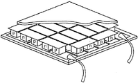
열전 모듈은, 전기적으로 직렬로 연결되어 있고 열적으로는 병렬로 연결되어 있는 p- 및 n-타입 부품들로 구성된다. 도 2는 이러한 모듈을 도시한다. Thermoelectric modules are composed of p- and n-type components electrically connected in series and thermally connected in parallel. 2 shows such a module.
통상적인 구조는 2개의 세라믹 판으로 구성되며, 이러한 세라믹 판들 사이에 개별적인 부품들이 교대로 설치되어 있다. 2개의 부품은 각각의 경우 말단면을 통해 전기-전도적으로 접촉하고 있다.The conventional structure consists of two ceramic plates, in which individual parts are alternately installed between these ceramic plates. The two parts are in each case electrically-conductively contacting through the end faces.
전기 전도성 접촉 이외에, 보호층 또는 납땜층으로서 작용하는 다양한 추가층들이 실제 물질들 위에 제공된다. In addition to the electrically conductive contacts, various additional layers serving as protective or soldering layers are provided on the actual materials.
그러나, 마지막으로, 2개의 부품들 사이의 전기 접점이 금속 브릿지를 경유하여 달성된다. However, finally, an electrical contact between the two parts is achieved via the metal bridge.
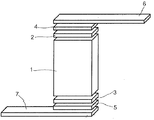
열전 모듈 컴포넌트의 필수 요소는 접점(contacting)이다. 상기 접점은 컴포넌트의 "심장"(컴포넌트의 목적하는 열전 효과를 제공함)에서의 물질과 "외부 세계" 사이를 물리적으로 연결한다. 이러한 접점의 구조는 도 1에 개략적으로 도시된다. An essential element of thermoelectric module components is contacting. The contact physically connects the material in the "heart" of the component (which provides the desired thermoelectric effect of the component) and the "outer world". The structure of this contact is shown schematically in FIG. 1.
컴포넌트 내부의 열전 물질(1)은 컴포넌트의 실제 효과를 제공한다. 이것이 열전 부품이다. 이것이 전체 구조물에서 그의 기능을 이행하도록, 상기 물질(1)을 통해 전류 및 열 플럭스가 흐른다. The
상기 물질(1)은 접점(4 및 5)을 경유하여 납(6 및 7)까지 각각 2개 이상의 측면에서 연결되어 있다. 이러한 경우에, 층(2 및 3)은, 상기 물질과 접점(4 및 5) 사이에 하나 이상의 선택적으로 요구되는 중간층(차단 물질, 납땜, 결합제 등)을 나타내고자 한 것이다. 서로의 쌍과 각각 관련된 2/3, 4/5, 6/7의 분절은 각각 동일할 수 있지만, 그래야만 하는 것은 아니다. 이것은, 결국, 특정한 구조 및 적용례, 뿐만 아니라 구조물을 통한 전류 또는 열 플럭스의 유동 방향에 비슷하게 좌우될 것이다. The
접점(4 및 5)은 중요한 역할을 갖는다. 이들은 상기 물질과 납 사이의 단단한 결합을 보장한다. 접점이 불량한 경우, 여기에서 높은 손실이 발생하고 컴포넌트의 성능을 많이 제한할 수 있다. 이러한 이유로 인하여, 상기 부품들과 접점은 종종 사용을 위해 상기 물질 위로 가압된다. 따라서 상기 접점들은 강한 기계 하중에 노출된다. 상승한(또는 감소한) 온도 및/또는 열 사이클이 포함되는 경우에는 언제나 추가로 이러한 기계 하중이 상승한다. 상기 컴포넌트에 생긴 물질의 열 팽창은, 필연적으로 기계적 응력을 유도하고, 이는 극단적인 경우에 접점의 균열에 의한 컴포넌트의 손상을 유발한다. The
이를 방지하기 위해서, 이러한 열적 응력들이 상쇄될 수 있도록, 사용된 접점들은 특정한 유연성 및 탄성 특성을 가져야만 한다. To prevent this, the contacts used must have specific flexibility and elastic properties so that these thermal stresses can be canceled out.
전체 구조물에 안정성을 부여하고 요구되는 최대로 균일한 열 커플링을 상기 부품들 마다 보장하도록, 캐리어 판이 필수적이다. 이것 때문에, 예를 들어 Al2O3, SiO2 또는 AlN과 같은 옥사이드 또는 니트라이드로 구성된, 세라믹이 통상적으로 사용된다. A carrier plate is essential to give stability to the entire structure and to ensure the required maximum uniform thermal coupling per part. For this reason, ceramics, usually composed of oxides or nitrides such as Al 2 O 3 , SiO 2 or AlN, are usually used.
각각의 경우 단지 편평한 표면만이 열전 모듈과 접촉할 수 있기 때문에, 통상적인 구조물은, 적용에 있어서 종종 한계가 있다. 모듈면과 열원/열 싱크 사이의 단단한 결합은, 충분한 열 플럭스를 보장하기 위해서, 필수적이다. Conventional structures are often limited in application, since in each case only flat surfaces can be in contact with the thermoelectric module. Tight coupling between the module surface and the heat source / heat sink is essential to ensure sufficient heat flux.
예를 들어 둥근 폐열 파이프와 같은 편평하지 않은 표면은, 통상적인 모듈과의 직접적인 접촉에 적합하지 않거나, 상기 편평하지 않은 표면을 편평한 모듈로 전환하기 위해서 상응하는 직선형 열 교환기 구조물이 요구된다. Non-flat surfaces, such as, for example, round waste heat pipes, are not suitable for direct contact with conventional modules or require corresponding straight heat exchanger structures to convert the non-flat surfaces into flat modules.
현재, 배기가스 열의 일부로부터 전기 에너지를 얻기 위해서, 자동차 및 트럭과 같은 차량에, 배기 시스템 또는 배기가스 재순환에 열전 모듈을 제공하고자 하는 시도가 있어왔다. 이러한 경우, 열전 모듈 요소의 뜨거운 쪽이 배기 가스 또는 배기관에 연결되는 반면, 찬 쪽이 냉각기에 연결된다. 발전될 수 있는 전기의 양은, 배기 가스로부터 열전 물질로의 열 플럭스 및 배기 가스의 온도에 좌우된다. 열 플럭스를 극대화시키기 위해서, 장치들이 종종 배기관에 설치된다. 그러나, 예를 들어 열 교환기의 설치가 배기 가스 내 압력 손실을 유도하고, 이는 다시 내연 엔진의 용납할 수 없는 증가된 소비를 유도하기 때문에, 이것은 제한된다. At present, attempts have been made to provide thermoelectric modules for exhaust systems or exhaust gas recirculation in vehicles such as automobiles and trucks in order to obtain electrical energy from a portion of the exhaust gas heat. In this case, the hot side of the thermoelectric module element is connected to the exhaust gas or the exhaust pipe, while the cold side is connected to the cooler. The amount of electricity that can be generated depends on the heat flux from the exhaust gas to the thermoelectric material and the temperature of the exhaust gas. In order to maximize the heat flux, devices are often installed in the exhaust pipe. However, this is limited, for example, because the installation of a heat exchanger leads to a pressure loss in the exhaust gas which in turn leads to an unacceptable increased consumption of the internal combustion engine.
통상적으로, 열전 발전기는 배기 시스템 내 배기 가스 촉매 전환기 밑에서 사용하기 위해 설치된다. 배기 가스 촉매 전환기의 압력 손실을 비롯하여, 이것은 종종 과도한 압력 손실을 유도하여, 열적-전도성 장치는 상기 배기 시스템에 제공될 수 없고; 오히려, 상기 열전 모듈이 배기관의 외부에 놓인다. 이 때문에, 상기 배기관은 다각형 단면을 갖도록 구조화되어야만 하며, 이로써 편평한 외면이 열전 물질과 단단하게 연결될 수 있다. Typically, thermoelectric generators are installed for use under an exhaust gas catalytic converter in an exhaust system. Including pressure loss of the exhaust gas catalytic converter, this often leads to excessive pressure loss such that thermally-conductive devices cannot be provided in the exhaust system; Rather, the thermoelectric module is external to the exhaust pipe. For this reason, the exhaust pipe must be structured to have a polygonal cross section, so that the flat outer surface can be firmly connected with the thermoelectric material.
열 전달 또는 발생되는 압력 손실 어떠한 것도 현재까지 만족스럽지 않다. No heat transfer or pressure loss generated is satisfactory to date.
본 발명의 목적은, 공지된 모듈의 단점을 피하고 낮은 압력 손실을 갖는 우수한 열 전달을 보장하는 것으로, 내연 엔진의 배기 시스템에 설치하기 위한 열전 모듈을 제공하는 것이다. It is an object of the present invention to provide a thermoelectric module for installation in an exhaust system of an internal combustion engine, by avoiding the disadvantages of known modules and ensuring good heat transfer with low pressure losses.
상기 목적은, 본 발명에 따라, 전기 전도성 접점을 통해 서로 교대로 연결된 p- 및 n-전도성 열전 물질 부품들로 구성된 열전 모듈로서, 상기 열전 모듈이, 유체 열 교환기 매체가 통과해서 유동할 수 있는 1mm 이하 직경의 복수개의 연속 채널들을 포함하는 마이크로 열 교환기와 열-전도적으로 연결되어 있는 열전 모듈에 의해 달성된다. The object is, in accordance with the present invention, a thermoelectric module composed of p- and n-conductive thermoelectric material parts alternately connected to each other via electrically conductive contacts, wherein the thermoelectric module is capable of flowing through a fluid heat exchanger medium. It is achieved by a thermoelectric module which is thermally conductively connected with a micro heat exchanger comprising a plurality of continuous channels of diameter up to 1 mm.
특히, 차량 배기 가스 촉매에서, 마이크로 열 교환기의 채널들이 내연 엔진 배기 가스 촉매의 워시코트로 코팅되는 것이 특히 유리하다. 이러한 방식에서는, 개별적인 배기 가스 촉매 전환기가 배제될 수 있고, 배기 시스템 내 압력 손실이 최소화된다. 일체형 디자인은 전체 구조물을 간단하게 만들고 배기 시스템 내 설치를 용이하게 한다. In particular, in vehicle exhaust gas catalysts, it is particularly advantageous for the channels of the micro heat exchanger to be coated with a washcoat of the internal combustion engine exhaust gas catalyst. In this way, individual exhaust gas catalytic converters can be eliminated and pressure losses in the exhaust system are minimized. The one-piece design simplifies the overall structure and facilitates installation in the exhaust system.
마이크로 열 교환기를 사용함으로써, 배기 가스로부터 열전 모듈로의 개선된 열 플럭스를 보장하고, 동시에 충분히 낮은 압력 손실을 보장하는 것이 가능하다. 본 발명에 따르면, 배기 가스는 마이크로 열 교환기의 마이크로채널을 통해 유동한다. 이러한 경우, 채널들은, 특히 NOx로부터 질소, 탄화수소로부터 C02 및 H20, 및 CO로부터 C02의 전환 중 하나 이상을 촉매작용하는 배기 가스 촉매로 코팅되는 것이 바람직하다. 특히 바람직하게는, 모든 이러한 전환들이 촉매작용된다. By using a micro heat exchanger, it is possible to ensure an improved heat flux from the exhaust gas to the thermoelectric module, while at the same time ensuring a sufficiently low pressure loss. According to the invention, the exhaust gas flows through the microchannels of the micro heat exchanger. In this case, the channels are preferably coated with an exhaust gas catalyst which catalyzes at least one of the conversion of nitrogen from NO x , C0 2 and H 2 0 from hydrocarbons, and C0 2 from CO. Especially preferably, all these conversions are catalyzed.
Pt, Ru, Ce, Pd와 같은 적합한 촉매 활성 물질이 공지되어 있고, 예를 들어 문헌[Stone, R. et al., Automotive Engineering Fundamentals, Society of Automotive Engineers 2004]에 기술된다. 이러한 촉매 활성 물질은 적절한 방식으로 마이크로 열 교환기의 채널에 적용된다. 바람직하게, 워시코트 형태의 적용이 예상될 수 있다. 이러한 경우에, 촉매는 현탁액의 형태로 박막으로서 마이크로 열 교환기의 내벽에 또는 그의 채널에 적용된다. 그다음, 촉매는 단일층 또는 동일하거나 다양한 조성을 갖는 다양한 층으로 구성될 수 있다. 그다음, 적용된 촉매는, 마이크로 열 교환기와 그의 코팅의 크기에 따라, 차량 내 사용 중인 내연 엔진에서 일반적으로 사용되는 배기가스 촉매 전환기를 전체적으로 또는 부분적으로 대체할 수 있다. Suitable catalytically active materials such as Pt, Ru, Ce, Pd are known and are described, for example, in Stone, R. et al., Automotive Engineering Fundamentals, Society of Automotive Engineers 2004. This catalytically active material is applied to the channels of the micro heat exchanger in a suitable manner. Preferably, application of the washcoat form may be envisaged. In this case, the catalyst is applied to the inner wall of the micro heat exchanger or to its channel as a thin film in the form of a suspension. The catalyst may then consist of a single layer or of various layers having the same or different compositions. The applied catalyst can then replace, in whole or in part, the exhaust gas catalytic converter commonly used in internal combustion engines in use in vehicles, depending on the size of the micro heat exchanger and its coating.
도 1은 열전 모듈의 접점을 보여주는 개략도이다.
도 2는, p- 및 n- 타입 부품들로 구성된 열전 모듈의 통상적인 구조를 도시한다.
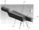
도 3은, 열전 발전기의 구성을 도시한 3차원 도면이다.
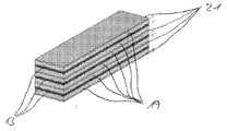
도 4는, 열전 발전기의 층 구성을 도시한 3차원 도면이다. 1 is a schematic view showing a contact of a thermoelectric module.
2 shows a typical structure of a thermoelectric module composed of p- and n- type components.
3 is a three-dimensional view showing the configuration of a thermoelectric generator.
4 is a three-dimensional view showing the layer configuration of the thermoelectric generator.
본 발명에 따르면, "마이크로 열 교환기"라는 용어는, 1mm 이하, 특히 바람직하게는 0.8mm 이하 직경의 복수개의 연속 채널들을 갖는 열 교환기를 의미하고자 한다. 최소 직경은, 기술적 실현가능성에 의해서만 설정되고 바람직하게는, 대략 50㎛, 특히 바람직하게는 대략 100㎛이다. According to the invention, the term "micro heat exchanger" is intended to mean a heat exchanger having a plurality of continuous channels of diameter of 1 mm or less, particularly preferably 0.8 mm or less. The minimum diameter is set only by technical feasibility and is preferably approximately 50 μm, particularly preferably approximately 100 μm.
상기 채널은 임의의 적절한 단면, 예를 들어 둥근형, 타원형, 다각형, 예를 들어 사각형, 삼각형 또는 별형을 가질 수 있다. 여기서, 채널의 마주보는 모서리 또는 지점들 사이 중 가장 짧은 거리를, 직경으로 한다. 채널들은 또한, 편평하도록 형성될 수 있고, 이러한 경우, 직경은 바운딩(bounding) 면들 사이의 거리로서 정의된다. 이것은, 특히 판들 또는 층들로 구성된 열 교환기의 경우이다. 작동하는 동안, 열 교환기 매체는 연속 채널을 통해 유동하고, 이때 열은 열 교환기로 이동한다. 열 교환기는 다른 한편으로 열전 모듈에 열적으로 연결되어, 열 교환기로부터 열전 모듈로 우수하게 열 전달된다. The channel may have any suitable cross section, for example round, oval, polygonal, for example square, triangular or star shaped. Here, the shortest distance between the opposite edges or points of the channel is taken as the diameter. The channels can also be formed to be flat, in which case the diameter is defined as the distance between the bounding faces. This is especially the case for heat exchangers consisting of plates or layers. During operation, the heat exchanger medium flows through the continuous channel, where heat moves to the heat exchanger. The heat exchanger, on the other hand, is thermally connected to the thermoelectric module, for excellent heat transfer from the heat exchanger to the thermoelectric module.
마이크로 열 교환기는, 임의의 적절한 물질로부터 임의의 적절한 방식으로 구성될 수 있다. 예를 들어, 연속 채널이 도입되어 있는, 열 전도성 물질의 블록으로 제조될 수 있다. The micro heat exchanger can be constructed in any suitable manner from any suitable material. For example, it can be made from a block of thermally conductive material, into which continuous channels are introduced.
임의의 적절한 물질들, 예를 들어 플라스틱, 예를 들어 폴리카보네이트, 액정 중합체, 예를 들어 제니쓰(Zenith, 등록상표, 듀퐁(DuPont)), 폴리에터 에터 케톤(PEEK) 등이 재료로서 사용될 수 있다. 금속들, 예를 들어, 철, 구리, 알루미늄 또는 적합한 합금, 예를 들어 알루미늄-철, 페크랄로이(Fecralloy)가 사용될 수 있다. 세라믹 또는 무기 옥사이드 물질, 예를 들어 알루미늄 옥사이드 또는 지르코늄 옥사이드 또는 코르디에라이트(cordierite)가 추가로 사용될 수 있다. 또한, 이것은 복수개의 전술한 물질로 구성된 복합 물질일 수도 있다. 마이크로 열 교환기는 바람직하게는 고온-내성 합금(1000-1200℃), 페크랄로이, Al-함유 철 합금, 스테인레스 강, 코르디에라이트로 구성된다. 마이크로채널은, 예를 들어 레이저 방법, 에칭, 천공 등에 의해 임의의 적절한 방식으로 열 전도성 물질의 블록에 도입될 수 있다.Any suitable materials such as plastics such as polycarbonate, liquid crystalline polymers such as Zenith®, DuPont, polyether ether ketones (PEEK) and the like can be used as the material. Can be. Metals such as iron, copper, aluminum or suitable alloys such as aluminum-iron, Fecralloy can be used. Ceramic or inorganic oxide materials such as aluminum oxide or zirconium oxide or cordierite may further be used. It may also be a composite material composed of a plurality of the aforementioned materials. The micro heat exchanger is preferably composed of a hot-resistant alloy (1000-1200 ° C.), pecralloy, an Al-containing iron alloy, stainless steel, cordierite. The microchannels can be introduced into the block of thermally conductive material in any suitable manner, for example by laser method, etching, perforation or the like.
대안으로서, 마이크로 열 교환기는 또한 상이한 판, 층 또는 튜브로 구성될 수 있으며, 이는 후속적으로 서로 예를 들어 접착제 결합 또는 용접에 의해 연결된다. 판, 층 또는 튜브는, 이러한 경우에, 마이크로채널보다 미리 제공될 수 있고, 그다음 조립될 수 있다. As an alternative, the micro heat exchanger can also be composed of different plates, layers or tubes, which are subsequently connected to one another, for example by adhesive bonding or welding. The plate, layer or tube can in this case be provided in advance of the microchannels and then assembled.
소결 방법에 의해 분말로부터 마이크로 열 교환기를 제조하는 것이 특히 바람직하다. 금속 분말 및 세라믹 분말 둘다가 분말로서 사용될 수 있다. 금속 및 세라믹으로 구성된 혼합물, 또는 상이한 금속들로 구성된 혼합물, 또는 상이한 세라믹들로 구성된 혼합물도 가능하다. 적합한 금속 분말은 예를 들어 페라이트계 강, 페크랄로이 또는 스테인레스 강으로 구성된 분말을 포함한다. 소결 방법에 의한 마이크로 열 교환기의 생성은, 임의의 바람직한 구조물을 제조하는 것을 가능하게 한다. Particular preference is given to producing a micro heat exchanger from the powder by the sintering method. Both metal powders and ceramic powders can be used as the powder. Mixtures of metals and ceramics, or mixtures of different metals, or mixtures of different ceramics are also possible. Suitable metal powders include, for example, powders composed of ferritic steel, pecralloy or stainless steel. The production of the micro heat exchanger by the sintering method makes it possible to produce any desired structure.
마이크로 열 교환기를 위한 물질로서 금속을 사용하면, 우수한 열 전도도의 이점을 제공한다. 대조적으로, 세라믹은 우수한 열 저장능을 갖고, 이들은 온도 요동을 상쇄하기 위해서 특히 사용될 수 있다. The use of metal as the material for the micro heat exchanger provides the advantage of good thermal conductivity. In contrast, ceramics have good heat storage capacity and they can be used particularly to compensate for temperature fluctuations.
플라스틱이 마이크로 열 교환기를 위한 재료로서 사용되는 경우, 마이크로 열 교환기를 통해 유동하는 배기 가스의 온도로부터 플라스틱을 보호하기 위한 코팅을 적용하는 것이 필요하다. 이러한 코팅은 "열 배리어(barrier) 코팅"으로도 지칭된다. 배기가스의 고온을 고려할 때, 플라스틱 물질로 구성된 마이크로 열 교환기의 모든 표면을 코팅하는 것이 필요하다. If plastic is used as the material for the micro heat exchanger, it is necessary to apply a coating to protect the plastic from the temperature of the exhaust gases flowing through the micro heat exchanger. Such coatings are also referred to as “heat barrier coatings”. Given the high temperatures of the exhaust gases, it is necessary to coat all surfaces of micro heat exchangers made of plastic material.
본 발명에 따라 사용된 마이크로 열 교환기의 외부 치수는 바람직하게는 60 x 60 x 20mm3 내지 40 x 40 x 8mm3이다.The external dimensions of the micro heat exchanger used according to the invention are preferably from 60 x 60 x 20 mm 3 to 40 x 40 x 8 mm 3 .
마이크로 열 교환기의 체적과 관련하여 마이크로 열 교환기의 비(specific) 열 전달 면적은 바람직하게는 0.1 내지 5m2/l, 특히 바람직하게는 0.3 내지 3m2/l, 특히 0.5 내지 2m2/l이다.The specific heat transfer area of the micro heat exchanger with respect to the volume of the micro heat exchanger is preferably 0.1 to 5 m 2 / l, particularly preferably 0.3 to 3 m 2 / l, especially 0.5 to 2m 2 / l.
적절한 마이크로 열 교환기는, 예를 들어 인스티튜트 퓌르 마이크로테크닉 마인츠 게임베하(Institut fur Mikrotechnik Mainz GmbH)에서 시판중이다. IMM은 다양한 구조의 마이크로구조화된 열 교환기를 제공하고, 특히 900℃의 최대 작동 온도를 위한 마이크로구조화된 고온 열 교환기를 제공한다. 이러한 고온 열 교환기의 치수는 약 80 x 50 x 70mm3이고 (다른 적용례의 경우) 역류(counterflow) 원리에 따라 작동한다. 이것의 압력 손실은 50 mbar 미만이고, 비 열 전달 면적은 약 1m2/l이다. Suitable micro heat exchangers are commercially available, for example, from Institut fur Mikrotechnik Mainz GmbH. IMM provides microstructured heat exchangers of various structures, in particular microstructured high temperature heat exchangers for maximum operating temperatures of 900 ° C. The dimensions of this high temperature heat exchanger are about 80 x 50 x 70 mm 3 (for other applications) and operate according to the counterflow principle. Its pressure loss is less than 50 mbar and the specific heat transfer area is about 1 m 2 / l.
다른 마이크로 열 교환기는, VDI/VDE-테크놀로지젠트룸 인포메이션스테크닉 게임베하(VDI/VDE-Technologiezentrum Informationstechnik GmbH(www.nanowelten.de))에 의해 공개되었다. 마이크로 열 교환기는 추가로 에르펠트 마이크로테크니크 BTS 게엠베하(Ehrfeld Mikrotechnik BTS GmbH, 벤델스하임 소재) 및 도버 마켓 서비스 게임베하(Dover Market Services GmbH)의 지사인 SWEP 마켓 서비스(퓌르트 소재)에서 공급된다. Another micro heat exchanger was published by VDI / VDE-Technologiezentrum Informationstechnik GmbH (www.nanowelten.de). The micro heat exchanger is additionally supplied by SWEP Market Service (Fuerte), a branch of Ehrfeld Mikrotechnik BTS GmbH, Wendelsheim and Dover Market Services GmbH. .
마이크로 열 교환기는, 가능한 최고의 열 전도도를 갖도록 하는 방식으로 열전 모듈에 연결되도록 한다. 구조 및 재료 구성에 따라, 이것을 열전 모듈에 직접 열-전도적으로 연결할 수 있다. 또한 열전 모듈이 편평한 것이 가능하고, 열전 물질 부품 위에서, 열전 모듈이, 뜨거운 쪽에 마이크로 열 교환기에 열-전도적으로 연결된 캐리어 판을 갖는 것도 가능하다. 캐리어 판을 위한 적절한 재료는 도입부에서 언급하였다. The micro heat exchanger is intended to be connected to the thermoelectric module in such a way as to have the highest thermal conductivity possible. Depending on the structure and material construction, it may be directly thermally conductively connected to the thermoelectric module. It is also possible for the thermoelectric module to be flat, and it is also possible for the thermoelectric module to have a carrier plate thermally conductively connected to the micro heat exchanger on the hot side. Suitable materials for the carrier plate are mentioned in the introduction.
마이크로 열 교환기는 열전 모듈과 일체형으로 형성되는 것이 바람직하다. 이러한 경우에, 예를 들어 열전 모듈에 직접 마이크로 열 교환기를 소결하는 것도 가능하다. 이것은 열전 모듈의 표면의 형태와 무관하게, 고도로 열-전도성인 연결이 수득된다는 이점을 갖는다. The micro heat exchanger is preferably formed integrally with the thermoelectric module. In this case, it is also possible to sinter the micro heat exchanger, for example, directly into the thermoelectric module. This has the advantage that a highly thermally conductive connection is obtained, regardless of the shape of the surface of the thermoelectric module.
이를 통해 유동하는 가스에 대해 열 교환기의 연속 채널들을 통해 발생하는 압력 손실은, 바람직하게는 100 mbar 이하, 특히 50 mbar 이하이다. 이러한 압력 손실은 내연 엔진의 증가된 연료 소비를 유도하지는 않는다. 특히, 배기 가스가 유동하는 채널들이 평행하게 진행되고 한쪽의 주입구 및 다른쪽의 배출구에 연결되도록 마이크로 열 교환기가 배열되는 경우, 압력 손실이 발생할 수 있다. 배기 가스가 유동하는 채널의 길이는, 이러한 경우, 바람직하게는 60 mm 이하, 특히 40 mm 이하이다. 하나 초과의 마이크로 열 교환기가 사용되는 경우, 개별적인 열 교환기들의 채널이 비슷하게 평행하게 진행되도록 마이크로 열 교환기는 비슷하게는 병렬로 연결되고 공통 주입구 및 공통 배출구로 연결된다.The pressure loss occurring through the continuous channels of the heat exchanger for the gas flowing through it is preferably 100 mbar or less, in particular 50 mbar or less. This pressure loss does not lead to increased fuel consumption of the internal combustion engine. In particular, pressure loss may occur when the micro heat exchanger is arranged such that the channels through which the exhaust gas flows run in parallel and are connected to one inlet and the other outlet. The length of the channel through which the exhaust gas flows is in this case preferably 60 mm or less, in particular 40 mm or less. If more than one micro heat exchanger is used, the micro heat exchangers are similarly connected in parallel and connected to a common inlet and common outlet so that the channels of the individual heat exchangers run similarly in parallel.
마이크로 열 교환기의 열-교환면은, 내연 엔진, 특히 차량 내의 내연 엔진의 배기관 또는 배기 시스템에 직접 설치될 수 있다. 이러한 경우에 고정식으로 또는 제거가능하게 설치될 수도 있다. 열-교환면은 또한 열전 모듈로 단단히 캡슐화될 수 있다. The heat-exchange surface of the micro heat exchanger can be installed directly in the exhaust pipe or exhaust system of an internal combustion engine, in particular an internal combustion engine in a vehicle. In such cases it may be fixed or removable. The heat-exchange surface can also be tightly encapsulated in a thermoelectric module.
마이크로 열 교환기에 촉매 물질의 워시코트가 제공되면, 원래 배기가스 촉매 전환기의 위치에서 배기 시스템에 설치될 수도 있다. 이러한 방식으로, 높은 배기 가스 온도가 마이크로 열 교환기에 공급될 수 있다. 심지어 마이크로 열 교환기의 배기 가스 촉매에서의 화학적 전환으로 인하여 온도가 증가하여, 공지된 시스템에서 보다 효율적인 열 전달이 발생할 수도 있다. If the microheat exchanger is provided with a washcoat of catalytic material, it may be installed in the exhaust system at the location of the original exhaust catalytic converter. In this way, high exhaust gas temperatures can be supplied to the micro heat exchanger. Even chemical conversion in the exhaust gas catalyst of the micro heat exchanger may increase the temperature, resulting in more efficient heat transfer in known systems.
열전 모듈의 개선된 효율은 또한 개선된 열 플럭스에 의해 달성된다. The improved efficiency of the thermoelectric module is also achieved by the improved heat flux.
과도한 온도에 대한 보호를 위한 보호층이 추가로 열전 모듈과 마이크로 열 교환기 사이에 제공될 수도 있다. 상 변화 층으로서 지칭되는 이러한 층은, 바람직하게는 250℃ 내지 1700℃의 범위의 융점을 갖는, 무기 금속 염 또는 금속 합금으로 구성된다. 적절한 금속 염은, 예를 들어 리튬, 나트륨, 칼륨, 루비듐, 세슘, 마그네슘, 칼슘, 스트론튬 및 바륨의 불소화물, 염소화물, 브롬화물, 요오드화물, 설페이트, 니트레이트, 카보네이트, 크로메이트, 몰리브데이트, 바나데이트 및 텅스테이트이다. 이원 또는 삼원 공융물을 형성하는, 이러한 유형의 적절한 염의 혼합물이 바람직하게 사용된다. 이들은 또한 4원 공융물 또는 5원 공융물을 형성할 수도 있다. A protective layer for protection against excessive temperatures may additionally be provided between the thermoelectric module and the micro heat exchanger. Such a layer, referred to as a phase change layer, is composed of an inorganic metal salt or metal alloy, preferably having a melting point in the range of 250 ° C to 1700 ° C. Suitable metal salts are, for example, fluorides, chlorides, bromide, iodides, sulfates, nitrates, carbonates, chromates, molybdates of lithium, sodium, potassium, rubidium, cesium, magnesium, calcium, strontium and barium , Vanadate and tungstate. Mixtures of suitable salts of this type, which form binary or ternary eutectics, are preferably used. They may also form quaternary eutectics or five-way eutectics.
다르게는, 예를 들어 아연, 마그네슘, 알루미늄, 구리, 칼슘, 실리콘, 인 및 안티몬인 금속으로부터 출발하는 2원, 3원, 4원 또는 5원 공융물을 형성하는, 상-변화 물질 및 이들의 조합으로서 금속 합금을 사용하는 것도 가능하다. 금속 합금의 융점은, 이러한 경우에, 200℃ 내지 1800℃의 범위이다.Alternatively, phase-change materials and their forming, for example, binary, tertiary, quaternary or 5-membered eutectics starting from metals which are zinc, magnesium, aluminum, copper, calcium, silicon, phosphorus and antimony It is also possible to use metal alloys as a combination. The melting point of the metal alloy is in this case in the range of 200 ° C to 1800 ° C.
열전 모듈은, 특히 니켈, 지르코늄, 티탄, 은 및 철과 같은 금속을 사용하는 경우, 또는 니켈, 크롬, 철, 지르코늄 및/또는 티탄에 기초한 합금을 사용하는 경우, 보호층으로 캡슐화될 수 있다. Thermoelectric modules can be encapsulated in a protective layer, in particular when using metals such as nickel, zirconium, titanium, silver and iron, or when alloys based on nickel, chromium, iron, zirconium and / or titanium are used.
예를 들어 연속으로 연결된, 하나 이상의 열전 모듈들은 내연 엔진의 배기 시스템과 일체화될 수 있다. 이러한 경우에, 상이한 열전 물질을 포함하는 열전 모듈도 조합될 수 있다. 일반적으로, 내연 엔진의 배기 가스의 온도 범위에 적합한 것인 모든 적합한 열전 물질을 사용하는 것이 가능하다. 적합한 열전 물질의 예는 스쿠테루다이트(skutterudite), 예를 들어 CoSb3, RuPdSb6, TX6(여기서, T = Co, Rh, Ir이고 X = P, As, Sb); X2Y8Z24(여기서, X = 란탄족, 악티늄족, 알칼리 토금속, 알칼리 금속, Th, IV족 원소이다); 하프 호이슬러(Heusler) 화합물, 예를 들어 TiNiSn, HfPdSn 및 금속간(intermetallic) 합금; 클라쓰레이트(clathrate), 예를 들어 Zn4Sb3, Sr8Ga16Ge30, Cs8Sn44, Co4TeSb4; 옥사이드, 예를 들어 NaxCoO2, CaCo4O9, Bi2Sr2Co2OySr2TiO4, Sr3Ti2O7, Sr4Ti3O10, R1-xMxCoO3(여기서, R = 희토금속이고 M = 알칼리 토금속이다); Srn+1TinO3n+1(여기서, n은 정수이다); YBa2Cu3O7-x; 실리사이드, 예를 들어 FeSi2, Mg2Si, Mn15Si26; 보라이드, 예를 들어 B4C, CaB6; Bi2Ce3 및 그의 유도체, PbCe 및 그의 유도체, 안티모나이드, 예를 들어 아연 안티모나이드, 진틀(Zintl)상, 예를 들어 Yb14MnSb4이다.For example, one or more thermoelectric modules, connected in series, may be integrated with the exhaust system of the internal combustion engine. In such cases, thermoelectric modules comprising different thermoelectric materials may also be combined. In general, it is possible to use all suitable thermoelectric materials which are suitable for the temperature range of the exhaust gas of the internal combustion engine. Examples of suitable thermoelectric materials include skutterudite, for example CoSb 3 , RuPdSb 6 , TX 6 (where T = Co, Rh, Ir and X = P, As, Sb); X 2 Y 8 Z 24 , wherein X = lanthanide, actinium group, alkaline earth metal, alkali metal, Th, group IV element; Half-Heusler compounds such as TiNiSn, HfPdSn and intermetallic alloys; Clathrates such as Zn 4 Sb 3 , Sr 8 Ga 16 Ge 30 , Cs 8 Sn 44 , Co 4 TeSb 4 ; Oxides such as Na x CoO 2 , CaCo 4 O 9 , Bi 2 Sr 2 Co 2 O y Sr 2 TiO 4 , Sr 3 Ti 2 O 7 , Sr 4 Ti 3 O 10 , R 1-x M x CoO 3 Where R = rare earth metal and M = alkaline earth metal; Sr n + 1 Ti n O 3n + 1 where n is an integer; YBa 2 Cu 3 O 7-x ; Silicides such as FeSi 2 , Mg 2 Si, Mn 15 Si 26 ; Borides such as B 4 C, CaB 6 ; Bi 2 Ce 3 and its derivatives, PbCe and its derivatives, antimonides such as zinc antimonide, Zintl phase, for example Yb 14 MnSb 4 .
본 발명은 바람직하게는 자동차 또는 트럭과 같은 차량에서 내연 엔진의 배기 시스템에서의 전술한 바와 같은 열전 모듈의 용도에 관한 것이다. 이러한 경우에, 상기 열전 모듈은, 배기 가스의 열로부터 전기를 발생시키기 위해 특히 사용된다. The present invention preferably relates to the use of a thermoelectric module as described above in an exhaust system of an internal combustion engine in a vehicle such as an automobile or a truck. In this case, the thermoelectric module is used in particular for generating electricity from the heat of the exhaust gas.
그러나, 마이크로 열 교환기 위에 워시코트가 존재하는 경우, 바람직하게는 차량의 내연 엔진의 상온 시동(cold start) 동안 배기 가스 촉매를 예열하기 위해 열전 모듈이 반대로 사용될 수도 있다. 이러한 경우, 열전 모듈은 펠티에 요소로서 사용된다. 전압차가 상기 모듈에 적용되는 경우, 모듈은 찬쪽으로부터 뜨거운 쪽으로 열을 수송한다. 이로 인한 배기 가스 촉매의 예열은 촉매의 상온 시동 시간을 감소시킨다. However, if a washcoat is present on the micro heat exchanger, the thermoelectric module may be used in reverse to preheat the exhaust gas catalyst, preferably during the cold start of the internal combustion engine of the vehicle. In this case, the thermoelectric module is used as a Peltier element. When a voltage difference is applied to the module, the module transfers heat from the cold side to the hot side. This preheating of the exhaust gas catalyst reduces the startup temperature of the catalyst.
본 발명은 추가로, 배기 시스템과 일체형인, 전술한 하나 이상의 열전 모듈을 포함하는, 내연 엔진, 바람직하게는 차량의 내연 엔진의 배기 시스템에 관한 것이다. The invention further relates to an exhaust system of an internal combustion engine, preferably an internal combustion engine of a vehicle, comprising at least one thermoelectric module described above, which is integral with the exhaust system.
이러한 경우, 배기 시스템은 내연 엔진의 배출구와 연결되고 여기에서 배기 가스가 가공되는 시스템을 의미하고자 한다. In this case, the exhaust system is intended to mean a system which is connected to the outlet of the internal combustion engine and in which the exhaust gas is processed.
본 발명에 따른 열전 모듈은 많은 장점을 갖는다. 특히 마이크로 열 교환기가 배기 가스 촉매의 워시코트로 코팅되는 경우, 내연 엔진의 배기 시스템 내 압력 손실이 낮다. 상기 배기 시스템의 구조는, 하나의 일체화된 컴포넌트에 의해 상당히 간략화될 수 있다. 일체화된 컴포넌트가 배기 시스템 내 내연 엔진에 더욱 가까이 일체화되기 때문에, 보다 높은 배기 가스 온도가 열전 모듈에 공급될 수 있다. 펠티에 요소로서의 열전 모듈의 가열적 사용에 의해, 배기 가스 촉매가, 엔진의 상온 시동 동안 가열될 수 있다. The thermoelectric module according to the invention has many advantages. Especially when the micro heat exchanger is coated with the washcoat of the exhaust gas catalyst, the pressure loss in the exhaust system of the internal combustion engine is low. The structure of the exhaust system can be significantly simplified by one integrated component. Since the integrated component is integrated closer to the internal combustion engine in the exhaust system, higher exhaust gas temperatures can be supplied to the thermoelectric module. By the thermal use of the thermoelectric module as a Peltier element, the exhaust gas catalyst can be heated during the room temperature startup of the engine.
본 발명의 예시적인 실시양태는 도면에 도시되어 있고 하기 설명에서 보다 상세하게 설명된다. Exemplary embodiments of the invention are shown in the drawings and described in more detail in the following description.
도 3은, 예를 들어 차량의 배기 시스템으로 삽입될 수 있는 상태의 열전 발전기의 구성을 도시한 것이다. 3 shows a configuration of a thermoelectric generator in a state that can be inserted into, for example, an exhaust system of a vehicle.
내연 엔진으로부터 배기 가스가 유도되는 배기 파이프(10)는, 다기관(manifold)(11)으로 유도된다. 다기관(11)은, 배기 가스의 유동 방향에서 감소하는 단면적을 갖는다. 다기관(11)은 마이크로 열 교환기(13)에 인접하여 있다. 후자는, 배기 가스가 마이크로 열 교환기(13) 내 채널을 통해 유동하는 방식으로, 다기관(11)에 연결되어 있다. 마이크로 열 교환기 내 채널은 수집기(15)로 유도되고, 배기 가스가 마이크로 열 교환기 내 채널을 통해 유동한 후, 상기 수집기(15)를 통해 배기 가스는 추가 배기 파이프(17)로 안내되며, 추가 배기 파이프(17)가 일반적으로 내연 엔진의 배기가스에서 끝난다. The exhaust pipe 10 through which the exhaust gas is guided from the internal combustion engine is led to a manifold 11. The manifold 11 has a cross-sectional area that decreases in the flow direction of the exhaust gas. Manifold 11 is adjacent to
마이크로 열 교환기(13)는 한쪽에서 열전 모듈(19)에 각각 연결되어 있다. 상기 열전 모듈(19)은 마이크로 열 교환기의 반대쪽에서 냉각된다. 이러한 목적을 위해, 열전 모듈(19) 위로 유동하는 냉각 액체, 예를 들어 냉각수를 사용하는 것이 바람직하다. 이러한 경우, 우선 냉각수를 열 교환기, 예를 들어 마이크로 열 교환기 내 채널을 통해 유동시키는 것이 가능하다. 그러나, 이를 통해 냉각 액체가 냉각될 열전 모듈(19) 쪽 위로 유동하는 냉각 채널(21)을 제공하는 것이 바람직하며, 상기 냉각 채널(21)의 벽은 열전 모듈(19)로 형성된다. The
하나의 바람직한 실시양태에서, 마이크로 열 교환기(13), 열전 모듈(19) 및 냉각 채널(21)이 적층되되, 여기서 안쪽 부분에 위치한 상기 마이크로 열 교환기(13)는 각각의 경우 그의 대향 측면들에서 열전 모듈(19)과 연결되고, 따라서, 내부에 위치한 냉각 채널(21)은 각각의 경우 그의 대향 측면들에서 열전 모듈(19)과 연결된다. 상응하는 층 구조는 도 4의 예로 설명된다. 여기서, 층 구조물은 각각의 경우 상부쪽에서 및 밑면쪽에서 냉각 채널로 둘러싸여 있다. 냉각 채널(21)은 열전 모듈(19)에 인접하고, 상기 열전 모듈(19)은 반대쪽에서 마이크로 열 교환기(13)에 연결되어 있다. 마이크로 열 교환기(13) 다음에는 추가 열전 모듈(19) 및 추가 냉각 채널(21)이 뒤따른다. In one preferred embodiment, the
층 구조는, 배기 가스의 열을 사용하는 것 뿐만 아니라 좁은 공간에서 복수개의 열전 모듈(19)을 사용하는 것을 가능하게 한다. The layer structure makes it possible not only to use the heat of the exhaust gas but also to use the plurality of
개별적인 층들이 배기 파이프(10)의 주요 유동축에 대해 평행하게 진행되는 층 구조를 갖는 도 3 및 4에서 설명한 실시양태 이외에, 개별적인 층들이 배기 파이프(10)의 주요 유동축에 대해 수직으로 진행되도록 층 구조를 고안하는 것도 가능하다. 개별적인 층들의 배향과 무관하게, 마이크로 열 교환기(13)내 채널은 바람직하게는, 다기관(11)으로부터 수집기(15)로의 배기 파이프(10)의 주요 유동 방향에 대해 항상 횡방향으로 진행한다. In addition to the embodiments described in FIGS. 3 and 4, in which the individual layers have a layered structure running parallel to the main flow axis of the exhaust pipe 10, the individual layers are allowed to run perpendicular to the main flow axis of the exhaust pipe 10. It is also possible to devise a layer structure. Regardless of the orientation of the individual layers, the channel in the
도 3 및 4에서 설명한 바와 같은 층들의 배향의 경우, 개별적인 층들은 각각의 경우 하나의 마이크로 열 교환기(13) 및 하나의 열전 모듈(19)을 포함할 수 있거나, 다르게는 각각 서로 나란하게 위치한 복수개의 마이크로 열 교환기들(13) 및/또는 복수개의 열전 모듈(19)들을 포함할 수 있다. 복수개의 마이크로 열 교환기(13) 및 복수개의 열전 모듈(19)이 사용되는 경우, 그다음 이들은 동일한 크기 또는 상이한 크기를 갖는 접점 영역을 가질 수 있다. 바람직하게, 각각의 경우의 하나의 마이크로 열 교환기(13)가 하나의 열전 모듈(19)에 연결되도록 상기 접점 영역이 동일한 크기를 갖는다. 이러한 실시양태에서, 그다음 서로 연속하여 연결되어 있는 복수개의 스택들을 형성하되, 이때 개별적인 냉각 채널들(21)이 그의 주입구 및 배출구와 함께 서로 인접하도록 개별적인 스택들이 바람직하게 배향되어, 따라서 연속되는 스택들 위로 연속적인 냉각 채널을 형성하는 것이 바람직하다. 이러한 경우, 냉각 채널의 배향은, 냉각 액체 및 배기 가스가 서로에 대해 직교류로 안내되도록, 선택된다. 다르게는, 냉각 채널을 요구되는 임의의 다른 방향으로 배향하는 것도 가능하다. 따라서, 예를 들어, 냉각 채널은 마이크로 열 교환기 내 채널과 평행하게 진행할 수도 있다. In the case of the orientation of the layers as described in FIGS. 3 and 4, the individual layers may in each case comprise one
Claims (14)
상기 열전 모듈(19)이 편평하고, 서로 연결된 열전 물질 부품들 위에서, 마이크로 열 교환기(13)와 열-전도적으로 연결되어 있는 뜨거운 쪽에 캐리어 판(carrier plate)을 갖는, 열전 모듈.The method of claim 1,
The thermoelectric module (19) is flat and has a carrier plate on a hot side that is heat-conductively connected to the micro heat exchanger (13), on the interconnected thermoelectric material components.
상기 마이크로 열 교환기(13)가 열전 모듈(19)과 일체형으로 형성되어 있는, 열전 모듈.The method of claim 1,
The thermoelectric module, wherein the micro heat exchanger (13) is formed integrally with the thermoelectric module (19).
상기 열전 모듈(19)과 마이크로 열 교환기(13) 사이에 과도한 온도로부터 보호하기 위한 보호층이 제공되어 있는, 열전 모듈.3. The method according to claim 1 or 2,
A thermoelectric module is provided between the thermoelectric module (19) and the micro heat exchanger (13) for protection against excessive temperatures.
상기 보호 층이 250℃ 내지 1700℃ 범위의 융점을 갖는 무기 금속 염 또는 금속 합금으로 구성된, 열전 모듈.5. The method of claim 4,
And the protective layer is composed of an inorganic metal salt or a metal alloy having a melting point in the range of 250 ° C to 1700 ° C.
상기 마이크로 열 교환기의 채널이 차량 배기 가스 촉매의 워시코트(washcoat)로 코팅되어 있는, 열전 모듈.6. The method according to any one of claims 1 to 5,
The channel of the micro heat exchanger is coated with a washcoat of the vehicle exhaust gas catalyst.
상기 촉매가, NOx로부터 질소로의 전환, 탄화수소로부터 C02와 H20로의 전환, 및 CO로부터 C02로의 전환 중 하나 이상을 촉매작용하는, 열전 모듈.The method according to claim 6,
Wherein the catalyst catalyzes one or more of conversion of NO x to nitrogen, conversion of hydrocarbons to C0 2 and H 2 0, and conversion of CO to C0 2 .
가스 통과를 위한 열 교환기의 연속 채널을 통해 발생하는 압력 손실이 100 mbar 이하인, 열전 모듈.The method according to any one of claims 1 to 7,
Thermoelectric module with a pressure drop of up to 100 mbar occurring through the continuous channel of the heat exchanger for gas passage.
상기 마이크로 열 교환기가, 연속 채널이 도입되어 있는 열 전도성 물질의 블록(block)으로 제조되는, 열전 모듈.The method according to any one of claims 1 to 8,
Wherein the micro heat exchanger is made of a block of thermally conductive material into which a continuous channel is introduced.
마이크로 열 교환기의 체적과 관련된 비(specific) 열 전달 면적이 0.1 내지 5 m2/l인, 열전 모듈.10. The method according to any one of claims 1 to 9,
A thermoelectric module, wherein the specific heat transfer area associated with the volume of the micro heat exchanger is 0.1 to 5 m 2 / l.
상기 배기 가스의 열로부터 전기를 발생시키기 위한 용도.The method of claim 11,
For generating electricity from the heat of the exhaust gas.
Applications Claiming Priority (5)
| Application Number | Priority Date | Filing Date | Title |
|---|---|---|---|
| EP10186366.0 | 2010-10-04 | ||
| EP10186366 | 2010-10-04 | ||
| EP10190614.7 | 2010-11-10 | ||
| EP10190614 | 2010-11-10 | ||
| PCT/IB2011/054295 WO2012046170A1 (en) | 2010-10-04 | 2011-09-29 | Thermoelectric modules for exhaust system |
Publications (1)
| Publication Number | Publication Date |
|---|---|
| KR20130108381A true KR20130108381A (en) | 2013-10-02 |
Family
ID=45927281
Family Applications (1)
| Application Number | Title | Priority Date | Filing Date |
|---|---|---|---|
| KR1020137011384A KR20130108381A (en) | 2010-10-04 | 2011-09-29 | Thermoelectric modules for exhaust system |
Country Status (7)
| Country | Link |
|---|---|
| EP (1) | EP2625727A4 (en) |
| JP (1) | JP6117102B2 (en) |
| KR (1) | KR20130108381A (en) |
| CN (1) | CN103238227B (en) |
| BR (1) | BR112013007718A2 (en) |
| TW (1) | TW201230261A (en) |
| WO (1) | WO2012046170A1 (en) |
Families Citing this family (7)
| Publication number | Priority date | Publication date | Assignee | Title |
|---|---|---|---|---|
| JP6129852B2 (en) * | 2011-10-04 | 2017-05-17 | ビーエーエスエフ ソシエタス・ヨーロピアBasf Se | Exhaust system assembly |
| EP2913857B1 (en) * | 2012-11-27 | 2017-05-24 | Yasunaga Corporation | Mg-Si THERMOELECTRIC CONVERSION MATERIAL, METHOD FOR PRODUCING SAME, SINTERED BODY FOR THERMOELECTRIC CONVERSION, THERMOELECTRIC CONVERSION ELEMENT, AND THERMOELECTRIC CONVERSION MODULE |
| FR3008716B1 (en) | 2013-07-17 | 2015-08-07 | Commissariat Energie Atomique | PROCESS FOR PREPARING A NANOPARTICLE DEPOSITION OF A METAL OR ALLOY ON A SUBSTRATE, SUBSTRATE THUS OBTAINED, AND ITS USES IN A THERMO-ELECTRIC RECUPERATOR OR EGR VALVE |
| EP3195376A1 (en) * | 2014-09-18 | 2017-07-26 | Basf Se | Thermo-compression bonding of thermoelectric materials |
| WO2016074918A1 (en) * | 2014-11-11 | 2016-05-19 | Basf Se | Thermoelectric device |
| US9551257B1 (en) | 2015-07-27 | 2017-01-24 | Tenneco Automotive Operating Company Inc. | Arrangement of catalyzed TEG systems |
| CN111878193B (en) * | 2020-08-26 | 2021-11-05 | 杜慎之 | Heat radiator for engine exhaust system |
Family Cites Families (13)
| Publication number | Priority date | Publication date | Assignee | Title |
|---|---|---|---|---|
| JP3564274B2 (en) * | 1997-10-13 | 2004-09-08 | カルソニックカンセイ株式会社 | Waste heat power generator |
| CN2381023Y (en) * | 1998-12-16 | 2000-05-31 | 北方专业设计工艺局“Nord” | Thermoelectric cooler |
| JP2000286469A (en) * | 1999-03-30 | 2000-10-13 | Nissan Motor Co Ltd | Thermoelectric power-generating device |
| JP2004140202A (en) * | 2002-10-18 | 2004-05-13 | Mitsubishi Heavy Ind Ltd | Thermoelectric conversion system |
| US20050111188A1 (en) * | 2003-11-26 | 2005-05-26 | Anandaroop Bhattacharya | Thermal management device for an integrated circuit |
| JP4305252B2 (en) * | 2004-04-02 | 2009-07-29 | 株式会社デンソー | Waste heat recovery device |
| JP2007329349A (en) * | 2006-06-08 | 2007-12-20 | Denso Corp | Thermoelectric conversion device and manufacturing method thereof |
| EP2050148A2 (en) * | 2006-07-28 | 2009-04-22 | Bsst, Llc | High capacity thermoelectric temperature control systems |
| JP2008111653A (en) * | 2006-10-17 | 2008-05-15 | Cooligy Inc | Cooler |
| JP2009150294A (en) * | 2007-12-20 | 2009-07-09 | Hitachi Ltd | Exhaust gas treatment device |
| DE102008023937A1 (en) * | 2008-05-16 | 2009-11-19 | Emitec Gesellschaft Für Emissionstechnologie Mbh | Device for generating electrical energy from exhaust heat |
| DE102008063487A1 (en) * | 2008-12-17 | 2010-06-24 | Emitec Gesellschaft Für Emissionstechnologie Mbh | Device for generating electrical energy from an exhaust gas |
| CN101459397A (en) * | 2008-12-26 | 2009-06-17 | 大连海事大学 | Residue heat temperature difference electricity conversion power generation system for internal combustion engine |
-
2011
- 2011-09-29 KR KR1020137011384A patent/KR20130108381A/en not_active Application Discontinuation
- 2011-09-29 BR BR112013007718A patent/BR112013007718A2/en not_active IP Right Cessation
- 2011-09-29 JP JP2013532298A patent/JP6117102B2/en active Active
- 2011-09-29 EP EP11830269.4A patent/EP2625727A4/en not_active Withdrawn
- 2011-09-29 WO PCT/IB2011/054295 patent/WO2012046170A1/en active Application Filing
- 2011-09-29 CN CN201180058155.5A patent/CN103238227B/en not_active Expired - Fee Related
- 2011-10-04 TW TW100135936A patent/TW201230261A/en unknown
Also Published As
| Publication number | Publication date |
|---|---|
| TW201230261A (en) | 2012-07-16 |
| WO2012046170A1 (en) | 2012-04-12 |
| CN103238227A (en) | 2013-08-07 |
| EP2625727A4 (en) | 2014-06-11 |
| EP2625727A1 (en) | 2013-08-14 |
| CN103238227B (en) | 2016-05-04 |
| JP2013546167A (en) | 2013-12-26 |
| BR112013007718A2 (en) | 2017-10-10 |
| JP6117102B2 (en) | 2017-04-19 |
Similar Documents
| Publication | Publication Date | Title |
|---|---|---|
| JP6129852B2 (en) | Exhaust system assembly | |
| US9476617B2 (en) | Thermoelectric modules for an exhaust system | |
| JP6117102B2 (en) | Thermoelectric module for exhaust system | |
| US20170250334A1 (en) | Thermo-compression bonding of thermoelectric materials | |
| EP2686531B1 (en) | Exhaust train having an integrated thermoelectric generator | |
| EP2180534B1 (en) | Energy conversion devices and methods | |
| US20080017238A1 (en) | Thermoelectric device | |
| KR20110053353A (en) | Thermoelectric device | |
| US9293679B2 (en) | Thermoelectric module for a thermoelectric generator of a vehicle and vehicle having thermoelectric modules | |
| KR101724847B1 (en) | Thermoelectric Generation Device for vehicle | |
| JP2006086402A (en) | Tubular thermoelectric module and thermoelectric converting device | |
| WO2017126264A1 (en) | Thermoelectric power generation device | |
| TW201245569A (en) | Exhaust train having an integrated thermoelectric generator | |
| JP2017135968A (en) | Thermoelectric generator |
Legal Events
| Date | Code | Title | Description |
|---|---|---|---|
| A201 | Request for examination | ||
| E902 | Notification of reason for refusal | ||
| E601 | Decision to refuse application |