KR20130095264A - Display with coding pattern - Google Patents
Display with coding pattern Download PDFInfo
- Publication number
- KR20130095264A KR20130095264A KR1020137004515A KR20137004515A KR20130095264A KR 20130095264 A KR20130095264 A KR 20130095264A KR 1020137004515 A KR1020137004515 A KR 1020137004515A KR 20137004515 A KR20137004515 A KR 20137004515A KR 20130095264 A KR20130095264 A KR 20130095264A
- Authority
- KR
- South Korea
- Prior art keywords
- grid
- axis
- display
- coding pattern
- marks
- Prior art date
Links
Images


Classifications
-
- G—PHYSICS
- G06—COMPUTING; CALCULATING OR COUNTING
- G06F—ELECTRIC DIGITAL DATA PROCESSING
- G06F3/00—Input arrangements for transferring data to be processed into a form capable of being handled by the computer; Output arrangements for transferring data from processing unit to output unit, e.g. interface arrangements
- G06F3/01—Input arrangements or combined input and output arrangements for interaction between user and computer
- G06F3/03—Arrangements for converting the position or the displacement of a member into a coded form
- G06F3/0304—Detection arrangements using opto-electronic means
- G06F3/0317—Detection arrangements using opto-electronic means in co-operation with a patterned surface, e.g. absolute position or relative movement detection for an optical mouse or pen positioned with respect to a coded surface
- G06F3/0321—Detection arrangements using opto-electronic means in co-operation with a patterned surface, e.g. absolute position or relative movement detection for an optical mouse or pen positioned with respect to a coded surface by optically sensing the absolute position with respect to a regularly patterned surface forming a passive digitiser, e.g. pen optically detecting position indicative tags printed on a paper sheet
-
- G—PHYSICS
- G06—COMPUTING; CALCULATING OR COUNTING
- G06F—ELECTRIC DIGITAL DATA PROCESSING
- G06F3/00—Input arrangements for transferring data to be processed into a form capable of being handled by the computer; Output arrangements for transferring data from processing unit to output unit, e.g. interface arrangements
- G06F3/01—Input arrangements or combined input and output arrangements for interaction between user and computer
- G06F3/03—Arrangements for converting the position or the displacement of a member into a coded form
- G06F3/033—Pointing devices displaced or positioned by the user, e.g. mice, trackballs, pens or joysticks; Accessories therefor
- G06F3/0354—Pointing devices displaced or positioned by the user, e.g. mice, trackballs, pens or joysticks; Accessories therefor with detection of 2D relative movements between the device, or an operating part thereof, and a plane or surface, e.g. 2D mice, trackballs, pens or pucks
- G06F3/03545—Pens or stylus
Abstract
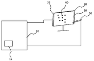
디스플레이(20)는 픽셀들(22)의 어레이를 포함하는 제1 표면을 포함하며, 어레이의 픽셀들(22)은 어레이 x-축 및 어레이 y-축을 규정하기 위하여 정렬된다. 디스플레이(20)는 제1 표면 위에 놓이는 제2 표면(32)을 추가로 포함하고, 제2 표면(32)에는 코딩 패턴(40)이 제공되며, 코딩 패턴(40)은 그리드에 따라 배열되는 마크들(46)을 포함하고, 그리드는 그리드 x-축 및 그리드 y-축을 규정하도록 배열된다. 그리드 x-축은 그리드 x-축이 어레이 x-축에 대해 소정 각도만큼 오프셋되는 방식으로 어레이 x-축 위에 놓인다.Display 20 includes a first surface comprising an array of pixels 22, with the pixels 22 of the array being aligned to define the array x-axis and array y-axis. The display 20 further comprises a second surface 32 overlying the first surface, the second surface 32 being provided with a coding pattern 40, the coding pattern 40 being a mark arranged along the grid. And a grid, the grid is arranged to define a grid x-axis and a grid y-axis. The grid x-axis lies on the array x-axis in such a way that the grid x-axis is offset by an angle relative to the array x-axis.
Description
발명은 디스플레이와의 사용자 상호작용(interaction)에 관한 것이다. 특히, 발명은 디스플레이 상에 배치될 물건에 관한 것이며, 물건에는 디스플레이 상에 인코딩된 정보의 레코딩을 허용하기 위한 코딩 패턴이 제공된다.The invention relates to user interaction with a display. In particular, the invention relates to an object to be placed on a display, the object being provided with a coding pattern to allow recording of the encoded information on the display.
디지털 디바이스들은 삶의 모든 면들에서 사용된다. 디지털 디바이스들이 사용자에게 정보를 제시하기 위한 몇몇 종류의 디스플레이를 갖는 것이 점점 흔해지고 있다. 이것은 TV 스크린들, 컴퓨터 모니터들, 태블릿 PC들, 이동 전화들, 또는 셀프-서비스 키오스크(self-service kiosk)들과 같은 단말들일 수 있다. 디지털 디바이스들은 또한 디바이스와 상호작용하도록 사용자가 정보를 입력하도록 허용한다. 이것과 관련하여, 키보드들, 마우스들, 조이스틱들 및 디지털 펜들과 같은 다수의 상이한 입력 디바이스들이 존재한다.Digital devices are used in all aspects of life. It is increasingly common for digital devices to have some kind of display for presenting information to a user. This may be terminals such as TV screens, computer monitors, tablet PCs, mobile phones, or self-service kiosks. Digital devices also allow a user to enter information to interact with the device. In this regard, there are a number of different input devices such as keyboards, mice, joysticks and digital pens.
디스플레이를 갖는 디지털 디바이스와 상호작용할 때, 종종 디스플레이 자체 상에 정보를 입력할 수 있는 것이 매우 편리할 것이다. 이것은 사용자가 항상 디스플레이 상에 초점을 맞추도록 허용하며, 사용자는 디스플레이와 입력 디바이스 사이에서 자신의 눈을 이동시킬 필요가 없다.When interacting with a digital device having a display, it will often be very convenient to be able to enter information on the display itself. This allows the user to always focus on the display, and the user does not need to move his eyes between the display and the input device.
이것과 관련하여, 터치 스크린들이 개발되었다. 센서 기술이 점점 더 싸지고 더욱 정확해짐에 따라 터치 스크린들은 점점 대중적이 되고 있다. 그러나 터치 감지 기술의 비용은 디스플레이의 사이즈에 따라 크게 좌우된다. 이것은 큰 디스플레이가 사용될 때, 터치 감지 기술을 사용하는 것이 매우 비싸짐을 의미한다. 그러므로 디스플레이 상의 위치(position)들을 감지하기 위한 더욱 저렴한 기술에 대한 필요성이 존재한다.In this regard, touch screens have been developed. As sensor technology becomes cheaper and more accurate, touch screens are becoming increasingly popular. However, the cost of touch sensing technology is highly dependent on the size of the display. This means that when a large display is used, using touch sensing technology is very expensive. Therefore, there is a need for cheaper techniques for sensing positions on the display.
위치들을 코딩하기 위한 패시브(passive) 위치-코딩 패턴을 사용하는 것이 종이 상의 핸드라이팅(handwriting)의 전자적 캡쳐 분야에 공지되었다. 여기서, 디지털 펜에 센서가 배열된다. 이것은 표면에 배열되는 진보된 기술이 존재하지 않음을 의미한다. 이런 이유로, 위치-코딩 패턴을 표면에 제공하는 비용은 다소 낮고, 사실상 표면의 사이즈와 무관하다. 대신에, 센서는 디지털 펜에 배치되며, 이에 따라, 센서 사이즈는 항상 동일하며, 전체 표면에 배열될 필요가 없다.It is known in the field of electronic capture of handwriting on paper to use passive position-coding patterns for coding positions. Here, the sensor is arranged in the digital pen. This means that no advanced technology exists on the surface. For this reason, the cost of providing a location-coding pattern to the surface is rather low and is virtually independent of the size of the surface. Instead, the sensor is placed in a digital pen, so that the sensor size is always the same and does not need to be arranged over the entire surface.
WO 01/48591에서, 위치-코딩 패턴이 컴퓨터 스크린에 통합되거나 컴퓨터 스크린 상에 배열되는 것이 제안된다. 대안적으로, 위치-코딩 패턴은 컴퓨터 스크린 또는 몇몇 다른 디스플레이 스크린 상에 전자적으로 디스플레이될 수 있다. 그러나 제1 해법은 디스플레이가 위치-코딩 패턴을 이용하여 제조되도록 요구한다. 이것은, 기술이 위치-코딩 패턴 없이 이미 생산된, 구(old) 디스플레이들에 대하여 사용될 수 없음을 의미한다. 제2 해법은 달성하기 어려운데, 이는 위치-코딩 패턴이 적절히 검출되게 하기 위하여 매우 정확하게 생성될 필요가 있기 때문이다.In WO 01/48591 it is proposed that the location-coding pattern is integrated into or arranged on a computer screen. Alternatively, the location-coding pattern can be displayed electronically on a computer screen or some other display screen. However, the first solution requires that the display be manufactured using a location-coding pattern. This means that the technology cannot be used for old displays, which have already been produced without a location-coding pattern. The second solution is difficult to achieve because it needs to be generated very accurately in order for the position-coding pattern to be detected properly.
JP 2001-243006에 개시된 바와 같이, 디스플레이 상에 배열될 수 있는 투명판 상에 위치-코딩 패턴을 배열하는 것이 또한 제안되었다. 디스플레이 상의 위치-코딩 패턴의 배열(arrangement)은 바람직하게는, 사용자에 의하여 경험되는 바에 따라, 디스플레이되는 이미지의 가시성(visibility)에 영향을 미치지 않아야 한다. 이것은 JP 2001-243006에 따라, 보이지 않는 엘리먼트들에 의해 위치-코딩 패턴을 형성함으로써 달성된다. 이것과 관련하여, 위치-코딩 패턴은 적외선 방사(radiation) 또는 자외선 방사를 반사하도록 배열될 수 있다.As disclosed in JP 2001-243006, it has also been proposed to arrange a position-coding pattern on a transparent plate which can be arranged on a display. The arrangement of the location-coding patterns on the display should preferably not affect the visibility of the displayed image, as experienced by the user. This is achieved by forming a position-coding pattern with invisible elements, according to JP 2001-243006. In this regard, the location-coding pattern may be arranged to reflect infrared radiation or ultraviolet radiation.
JP 2002-149331에 따라, 투명판 상의 위치-코딩 패턴은 x-좌표 및 y-좌표를 코딩하기 위하여 간헐적으로 배열되는 도트 어레이들에 의하여 형성될 수 있다. x-좌표 값들이 코딩되는 도트 어레이들 및 y-좌표 값들이 코딩되는 도트 어레이들은 교대로 형성되고 디스플레이 픽셀의 픽셀 피치(pitch)와 거의 동일한 피치로 형성된다. 더욱이, 도트들에 의하여 커버되는 전체 영역이 위치-코딩 패턴이 제공되는 판의 전체 영역에 대하여 매우 작도록, 인접한 도트 어레이들은 그들 사이에 큰 공간(spacing)을 두고 배열된다. 그러므로 JP 2002-149331에 따라, 도트 어레이들에 의하여 야기되는, 디스플레이된 이미지에 대한 임의의 역효과가 거의 없다.According to JP 2002-149331, the position-coding pattern on the transparent plate may be formed by dot arrays intermittently arranged to code the x- and y-coordinates. Dot arrays in which x-coordinate values are coded and dot arrays in which y-coordinate values are coded are alternately formed and formed at a pitch substantially equal to the pixel pitch of the display pixel. Moreover, adjacent dot arrays are arranged with large spacing between them so that the entire area covered by the dots is very small relative to the entire area of the plate provided with the position-coding pattern. Therefore, according to JP 2002-149331, there is little any adverse effect on the displayed image caused by the dot arrays.
발명의 목적은 다양한 디스플레이들로의 적용(application)에 적당한 코딩 패턴을 물건(product)에 제공하는 것이다. 발명의 추가적 목적은 코딩 패턴이 디스플레이된 이미지에 간섭하지 않는 것이다.It is an object of the invention to provide a product with a coding pattern suitable for application to various displays. A further object of the invention is that the coding pattern does not interfere with the displayed image.
발명의 제1 양상에 따라, 표면을 포함하는 물건이 관련되며, 표면은 표면 x-축 및 표면 y-축을 규정하기(define) 위한 에지들을 포함하고; 표면에는 코딩 패턴이 추가로 제공되고, 코딩 패턴은 그리드에 따라 배열되는 마크들을 포함하며, 그리드는 그리드 x-축 및 그리드 y-축을 규정하도록 배열되고; 그리드 x-축은 표면 x-축에 대해 소정 각도(an angle)만큼 오프셋된다.According to a first aspect of the invention, an object comprising a surface is involved, the surface comprising edges for defining a surface x-axis and a surface y-axis; The surface is further provided with a coding pattern, the coding pattern comprising marks arranged along the grid, the grid arranged to define the grid x-axis and the grid y-axis; The grid x-axis is offset by an angle with respect to the surface x-axis.
물건은 임의의 디스플레이 상에 코딩 패턴을 배열하는 가능성을 제공한다. 상이한 디스플레이들 사이에서 물건이 스위칭될 수 있도록, 물건은 휴대용이고, 디스플레이에 분리할 수 있게 부착가능할 수 있다.The article offers the possibility of arranging the coding pattern on any display. The article is portable and may be detachably attachable to the display so that the article can be switched between different displays.
디스플레이는 디스플레이 상에 이미지를 형성하기 위하여 제어되는 픽셀들의 어레이를 포함한다. 어레이의 픽셀들은 어레이 x-축 및 어레이 y-축을 규정하도록 정렬된다. 보통은, 어레이 x-축 및 어레이 y-축은 디스플레이의 각각의 에지들에 대해 평행할 것이다. 물건이 디스플레이에 부착될 때, 디스플레이의 각각의 에지들과 평행하게 표면의 에지들을 배열하는 것이 실용적(practical)이다. 이것은 표면 x-축이 어레이 x-축에 맞추어 조정될(aligned with) 것임을 의미한다. 표면 x-축에 관하여 소정 각도(an angle)만큼 오프셋되는 그리드 x-축으로 인하여, 그리드 x-축은 또한 물건이 부착되는 디스플레이의 어레이 x-축에 관하여 소정 각도만큼 오프셋될 것이다. 본 발명에 따라, 어레이 x-축에 대해 소정 각도를 형성하도록 그리드 x-축을 배열하여, 코딩 패턴의 그리드와 디스플레이의 픽셀 피치 간의 간섭 문제들이 방지될 수 있는 것이 실현되었다. 특히, 무아레(moire) 간섭 효과들이 사용자에게 가시적이지 않도록, 코딩 패턴은 디스플레이 픽셀들에 관하여 배열될 수 있다. 이런 이유로, 물건은 디스플레이의 특징들과 무관하게 임의의 디스플레이와 함께 사용하기에 적합할 수 있다. 따라서, 동일한 물건이 디스플레이들의 픽셀 피치를 고려할 필요 없이 상이한 디스플레이들 사이에서 스위칭될 수 있다. 더욱이, 상이한 픽셀 피치들에 대해 특정하게 적용되는(adapted to) 물건들을 생산할 필요는 없다.The display includes an array of pixels that are controlled to form an image on the display. The pixels of the array are aligned to define the array x-axis and the array y-axis. Usually, the array x-axis and array y-axis will be parallel to each edge of the display. When an article is attached to the display, it is practical to arrange the edges of the surface parallel to the respective edges of the display. This means that the surface x-axis will be aligned with the array x-axis. Due to the grid x-axis being offset by an angle with respect to the surface x-axis, the grid x-axis will also be offset by an angle with respect to the array x-axis of the display to which the object is attached. According to the present invention, it has been realized that by arranging the grid x-axis to form an angle with respect to the array x-axis, interference problems between the grid of the coding pattern and the pixel pitch of the display can be prevented. In particular, the coding pattern can be arranged relative to the display pixels such that moire interference effects are not visible to the user. For this reason, an object may be suitable for use with any display regardless of the features of the display. Thus, the same object can be switched between different displays without having to consider the pixel pitch of the displays. Moreover, there is no need to produce objects that are adapted to different pixel pitches.
대안적으로, 물건은 특정 디스플레이에 고정식으로 부착될 수 있다. 그러한 일 실시예에서, 물건이 연관되는 디스플레이의 픽셀 피치는 미리 알려질 수 있다. 이런 이유로, 적어도 이론적으로는 그리드 사이즈를 디스플레이의 픽셀 피치에 대해 맞추는 것이 가능할 것이다. 그러나 그리드 사이즈 및 픽셀 피치가 면밀히 조화되지 않는다면, 즉, 그리드 사이즈가 정수배(integer multiple) 픽셀 피치와 동일하거나 픽셀 피치가 정수배 그리드 사이즈와 동일하다면, 간섭 문제들이 발생할 수 있다. 그러므로 그리드 x-축이 표면 x-축에 대해 소정 각도만큼 오프셋되는 것을 보장함으로써, 물건 상에 코딩 패턴을 배열하는데 있어서의 정확성 요건들은 낮춰질 수 있다. 이것은 물건의 제조 비용들이 감소할 수 있음을 의미한다.Alternatively, the object can be fixedly attached to a particular display. In one such embodiment, the pixel pitch of the display with which the article is associated may be known in advance. For this reason, it would be possible, at least in theory, to match the grid size to the pixel pitch of the display. However, if grid size and pixel pitch are not closely matched, that is, if grid size is equal to integer multiple pixel pitch or pixel pitch is equal to integer grid size, interference problems may occur. Therefore, by ensuring that the grid x-axis is offset by an angle with respect to the surface x-axis, the accuracy requirements in arranging the coding pattern on the object can be lowered. This means that manufacturing costs of the article can be reduced.
뿐만 아니라, 디스플레이의 픽셀 피치에 대해 코딩 패턴의 그리드 사이즈를 맞출 필요성이 존재하지 않기 때문에, 상이한 타입들의 디스플레이들에 대해 의도되는 상이한 물건들은 모두 동일한 그리드 사이즈를 갖는 코딩 패턴들을 제공받을 수 있다. 이것은 코딩 패턴을 판독하기 위한 판독기가 미리 결정된 그리드 사이즈를 갖는 코딩 패턴을 판독할 때 사용하기 위하여 최적화될 수 있음을 의미한다. 그 후 이 판독기는 물건이 연관되는 디스플레이의 타입과 무관하게 임의의 물건의 코딩 패턴을 판독하기 위하여 사용될 수 있다.In addition, since there is no need to match the grid size of the coding pattern to the pixel pitch of the display, different objects intended for different types of displays may all be provided with coding patterns having the same grid size. This means that a reader for reading the coding pattern can be optimized for use when reading a coding pattern having a predetermined grid size. This reader can then be used to read the coding pattern of any object, regardless of the type of display with which the object is associated.
물건은 가시적 방사에 대해 투과성이어야 한다. 이것은 디스플레이에 적용될 때, 물건이 디스플레이된 이미지의 가시성에 영향을 미치지 않을 것임을 의미한다. 그러나 코딩 패턴은 투과성일 필요가 없다. 코딩 패턴은 예컨대, 적외선 방사를 산란식으로(diffusely) 반사할 수 있는 화이트 마크(white mark)들을 포함할 수 있다. 이 코딩 패턴은 사용자에게 거의 가시적이지 않을 것이며, 주로 디스플레이된 이미지의 콘트라스트(contrast)를 낮출 수 있다. 더욱이, 상기 설명된 바와 같이, 그리드 x-축이 디스플레이의 어레이 x-축에 대해 소정 각도만큼 오프셋되기 때문에, 코딩 패턴의 그리드와 디스플레이의 픽셀 피치 간의 간섭 문제들이 방지될 수 있다.The article must be transparent to visible radiation. This means that when applied to a display, the object will not affect the visibility of the displayed image. However, the coding pattern does not need to be transparent. The coding pattern may include, for example, white marks that may reflect infrared radiation scatteredly. This coding pattern will be hardly visible to the user and can mainly lower the contrast of the displayed image. Moreover, as described above, since the grid x-axis is offset by an angle with respect to the array x-axis of the display, interference problems between the grid of the coding pattern and the pixel pitch of the display can be prevented.
코딩 패턴의 마크들은 광학적으로 검출가능할 수 있다. 코딩 패턴을 광학적으로 감지하기 위하여 이미지 센서를 사용하는 판독기에 의하여 코딩 패턴이 검출될 수 있도록, 마크들은 입사 방사와 상호작용하도록 배열될 수 있다. 이것과 관련하여, 코딩 패턴은 적외선 방사를 산란식으로 반사하는 마크들을 포함할 수 있다. 그러나 코딩 패턴은 대안적으로 마크들을 포함할 수 있으며, 이 마크들은, 마크들이 표면의 이미지에서 검출되도록 허용하기 위하여 입사 방사의 정반사(specular reflection), 회절, 굴절, 흡수, 내부 전반사, 또는 브래그(Bragg) 반사를 제공하도록 배열된다.Marks of the coding pattern may be optically detectable. The marks can be arranged to interact with incident radiation so that the coding pattern can be detected by a reader using an image sensor to optically sense the coding pattern. In this regard, the coding pattern may include marks that scatter scatter infrared radiation. However, the coding pattern may alternatively comprise marks, which are specular reflections, diffractions, refractions, absorptions, total internal reflections, or Braggs of incident radiation to allow the marks to be detected in the image of the surface. Bragg) is arranged to provide reflection.
마크들이 자신들이 제공되는 표면으로부터 구분될 수 있도록, 마크들은 바람직하게는 물건의 획득된 이미지에서 큰 신호 대 잡음비를 제공해야 한다. 획득된 이미지에서 충분한 신호 대 잡음비를 제공하기 위하여 요구되는 마크들의 사이즈는 마크들이 입사 방사와 상호작용하는 방식에 따라 좌우될 수 있다. 예컨대, 산란식으로 반사하는 마크들을 사용하며, 이 마크들은 80-110 ㎛ 범위의 직경을 갖는 도트들일 수 있다.The marks should preferably provide a large signal to noise ratio in the acquired image of the object so that the marks can be distinguished from the surface on which they are provided. The size of the marks required to provide a sufficient signal-to-noise ratio in the acquired image may depend on how the marks interact with the incident radiation. For example, scatteringly reflective marks are used, which may be dots having a diameter in the range of 80-110 μm.
일 실시예에서, 코딩 패턴의 마크들은 디스플레이의 서브-픽셀보다 현저히 더 작은 사이즈일 수 있다. 서브-픽셀은 픽셀에 대해 하나의 컬러(colour), 통상적으로 적색, 녹색 또는 청색을 제공하는 엘리먼트이다. 서브-픽셀보다 현저히 작은 마크들로 인하여, 마크는 서브-픽셀을 완전히 커버하지 않을 것이다. 이것은 개별적인 마크들이 디스플레이의 개별 픽셀들의 경험 컬러에 영향을 미치지 않을 것임을 보장한다. 이런 이유로, 디스플레이의 경험 컬러에서의 잡음은 경감되거나 방지될 것이다.In one embodiment, the marks of the coding pattern may be significantly smaller in size than the sub-pixels of the display. A sub-pixel is an element that provides one color, typically red, green or blue, for a pixel. Due to the marks significantly smaller than the sub-pixel, the mark will not fully cover the sub-pixel. This ensures that the individual marks will not affect the experience color of the individual pixels of the display. For this reason, noise in the empirical color of the display will be reduced or prevented.
코딩 패턴의 마크들은 100 ㎛ 보다 작은 직경을 갖는 도트들일 수 있다. 이것은 큰 디스플레이 상에서 물건을 사용할 때 디스플레이의 경험 컬러에서의 잡음을 방지하는 것을 허용할 수 있다. 일 실시예에서, 코딩 패턴의 마크들은 80 ㎛보다 작은 직경을 갖는 도트들일 수 있다. 예컨대, 산란식으로 반사하는 마크들을 사용하며, 이 마크들은 60-80 ㎛ 범위의 직경을 갖는 도트들일 수 있다. 이것은 더 작은 픽셀 사이즈들을 갖는 더 많은 타입들의 디스플레이들을 갖는 물건을 사용하는 것을 가능하게 할 것이다. 다른 실시예들에서, 마크들은 40 ㎛보다 작은 직경을 갖는 도트들일 수 있다.The marks of the coding pattern may be dots with a diameter smaller than 100 μm. This may allow to avoid noise in the experience color of the display when using the object on a large display. In one embodiment, the marks of the coding pattern may be dots with a diameter smaller than 80 μm. For example, using scatteringly reflective marks, these marks may be dots having a diameter in the range of 60-80 μm. This will make it possible to use an object with more types of displays with smaller pixel sizes. In other embodiments, the marks may be dots with a diameter less than 40 μm.
일 실시예에서, 코딩 패턴의 마크들은 10 ㎛보다 큰 직경을 갖는 도트들일 수 있다. 도트의 직경이 더 클수록, 물건의 이미지에서 도트를 검출하는 것은 더 쉬워진다. 이런 이유로, 도트들이 너무 작게 만들어진다면, 도트들은 검출하기에 어려울 것이다. 일 실시예에서, 코딩 패턴의 마크들은 10-40 ㎛ 범위의 직경을 갖는 도트들일 수 있다. 그러한 실시예에서, 마크들은 입사 방사의 정반사를 제공하도록 배열될 수 있다.In one embodiment, the marks of the coding pattern may be dots with a diameter greater than 10 μm. The larger the diameter of the dot, the easier it is to detect the dot in the image of the object. For this reason, if the dots are made too small, the dots will be difficult to detect. In one embodiment, the marks of the coding pattern may be dots having a diameter in the range of 10-40 μm. In such an embodiment, the marks may be arranged to provide specular reflection of incident radiation.
일 실시예에서, 코딩 패턴의 마크들은 비대칭 형상으로 배열된다. 코딩 패턴의 마크들은 예를 들어, 타원형 또는 직사각형 도트들일 수 있다. 물건이 디스플레이 상에 배열될 때, 어레이 x-축에 평행한 방향에서의 마크의 연장부(extension)가 어레이 y-축에 평행한 방향에서의 마크의 연장부보다 더 크도록, 마크들이 표면 상에 배열될 수 있다. 이것은, 어레이 x-축을 따라 배향된 서브픽셀들을 갖는 디스플레이를 구비한 물건을 사용할 때, 즉, 서브픽셀들이 어레이 x-축의 방향으로 연장되는 짧은 면을 갖는 직사각형일 때, 유리할 수 있다. 그러한 배열에서, 마크는 큰 전체 면적을 가지면서 디스플레이의 서브픽셀과의 작은 중첩부를 가질 수 있다. 이것은 디스플레이의 경험 컬러에서의 잡음이 경감되거나 방지될 것임을 의미할 수 있다. 예컨대, 마크들은 70 ㎛의 짧은 직경 및 140 ㎛의 긴 직경을 갖는 타원형 도트들일 수 있다.In one embodiment, the marks of the coding pattern are arranged in an asymmetrical shape. The marks of the coding pattern may be oval or rectangular dots, for example. When the article is arranged on the display, the marks are placed on the surface such that the extension of the mark in the direction parallel to the array x-axis is greater than the extension of the mark in the direction parallel to the array y-axis. Can be arranged to. This may be advantageous when using an article with a display having subpixels oriented along the array x-axis, that is, when the subpixels are rectangular with short sides extending in the direction of the array x-axis. In such an arrangement, the mark may have a large total area while having a small overlap with the subpixels of the display. This may mean that noise in the experience color of the display will be reduced or prevented. For example, the marks may be elliptical dots having a short diameter of 70 μm and a long diameter of 140 μm.
일 실시예에서, 물건과 함께 사용될 디스플레이들의 픽셀 피치는 물건의 생산 이전에 결정된다. 알려진 픽셀 피치들을 사용하며, 상이한 픽셀 피치들과 고정된 그리드 사이즈를 갖는 코딩 패턴 사이의 상이한 오프셋 각도들에 대한 무아레 간섭 효과들에 대한 분석이 이루어진다. 분석은 적절한 오프셋 각도를 결정하는데 사용될 수 있다.In one embodiment, the pixel pitch of the displays to be used with the article is determined prior to production of the article. Using known pixel pitches, an analysis is made of moiré interference effects on different offset angles between different pixel pitches and a coding pattern with a fixed grid size. The analysis can be used to determine the appropriate offset angle.
예컨대, 하나의 물건은 대형 TV 스크린들과 함께 사용되도록 의도될 수 있는 반면, 다른 물건들은 소형 랩탑 디스플레이들 또는 이동 전화 디스플레이들과 함께 사용되도록 의도될 수 있다. 이들 상이한 타입들의 스크린들에 대한 픽셀 피치는 상당히 상이할 수 있다. 이런 이유로, 특정 물건에 대하여 적절한 오프셋 각도를 결정하기 위한 분석이 이루어질 수 있다. 그 후에, 코딩 패턴은 결정된 적절한 오프셋 각도를 사용하여 특정 물건 상에 제공된다.For example, one object may be intended for use with large TV screens, while other objects may be intended for use with small laptop displays or mobile phone displays. The pixel pitch for these different types of screens can be quite different. For this reason, an analysis can be made to determine the appropriate offset angle for a particular object. Thereafter, the coding pattern is provided on a particular object using the determined appropriate offset angle.
다른 실시예에서, 물건은 수 개의 상이한 타입들의 디스플레이들과 함께 사용하기 위하여 예비될 수 있다. 이것과 관련하여, 그리드 x-축은 표면 x-축에 대해 소정 각도만큼 오프셋될 수 있으며, 상기 각도는 코딩 패턴의 그리드 사이즈와 디스플레이의 픽셀 피치 간의 상이한 관계들에 대하여 가시적 무아레 간섭이 방지될 수 있도록 선택된다. 일 실시예에서, 그리드 x-축은 약 10-15°, 25-35°, 또는 대략 45°의 각도만큼 오프셋된다. 적절한 오프셋 각도는 그리드 사이즈와 픽셀 피치 간의 관계에 따라 좌우된다. 약 10-15° 또는 25-35°의 오프셋 각도를 사용하는 것은 표면이 어떠한 가시적 무아레 간섭 효과들도 발생하지 않고 가변 픽셀 피치들을 갖는 디스플레이들과 함께 사용되도록 허용한다. 적어도 몇몇 셋업들에 대해, 대략 45°, 예컨대 40-50°의 각도가 적절할 것임이 관찰되었다. 그러나 다른 오프셋 각도들이 더 적절할 수도 있다.In another embodiment, the article may be reserved for use with several different types of displays. In this regard, the grid x-axis can be offset by an angle relative to the surface x-axis, such that the angle can be prevented for visible moire interference with respect to different relationships between the grid size of the coding pattern and the pixel pitch of the display. Is selected. In one embodiment, the grid x-axis is offset by an angle of about 10-15 °, 25-35 °, or approximately 45 °. The appropriate offset angle depends on the relationship between grid size and pixel pitch. Using an offset angle of about 10-15 ° or 25-35 ° allows the surface to be used with displays with variable pixel pitches without causing any visible moire interference effects. For at least some setups it has been observed that an angle of approximately 45 °, such as 40-50 °, will be appropriate. However, other offset angles may be more appropriate.
코딩 패턴은, 그리드 교차점(intersection)들을 형성하도록 서로 교차하는 가상 그리드 라인들을 포함할 수 있으며, 여기서 적어도 몇몇 마크들은 정보를 코딩하도록 그리드 교차점들로부터 변위되고, 그리드 교차점으로부터의 마크의 변위의 방향은 마크에 의하여 코딩되는 값을 결정한다. 몇몇 그리드 라인들은 그리드 교차점들에 배치되는 마크들에 의하여 표시될 수 있다. 이것은 그리드 라인들의 검출을 가능하게 할 수 있다.The coding pattern may include virtual grid lines that intersect each other to form grid intersections, wherein at least some marks are displaced from the grid intersections to code the information, and the direction of displacement of the mark from the grid intersection is Determine the value coded by the mark. Some grid lines may be indicated by marks placed at grid intersections. This may enable detection of grid lines.
그리드 교차점들로부터의 마크들의 변위는 마크의 위치에서 디스플레이와의 국부적 간섭 효과들을 야기할 수 있다. 그러므로 그리드 교차점들로부터의 마크들의 변위는 어느 방향으로 마크가 변위되었는지 검출하는 능력을 유지하면서, 가능한 한 작아야 한다. 일 실시예에서, 그리드 교차점으로부터의 마크의 변위는 대략 50 ㎛이다. 그러나 다른 실시예에서, 그리드 교차점으로부터의 마크의 변위는 50 ㎛보다 작으며, 바람직하게는 10-30 ㎛ 범위이다. 일 실시예에서, 그리드 교차점으로부터의 마크의 변위는 마크의 직경의 대략 50%이다.Displacement of marks from grid intersections can cause local interference effects with the display at the position of the mark. Therefore, the displacement of the marks from the grid intersections should be as small as possible, while maintaining the ability to detect in which direction the mark has been displaced. In one embodiment, the displacement of the mark from the grid intersection is approximately 50 μm. However, in another embodiment, the displacement of the mark from the grid intersection is less than 50 μm, preferably in the range of 10-30 μm. In one embodiment, the displacement of the mark from the grid intersection is approximately 50% of the diameter of the mark.
다른 실시예에서, 코딩 패턴은 마크들을 포함할 수 있는데, 상기 마크들은 그리드를 규정하기 위하여 규칙적으로 배치된다. 이 실시예에서, 각각의 마크는 가상 그리드 라인들의 그리드 교차점에 배치될 수 있다. 마크들은 그 후 정보를 코딩하기 위하여 상이한 형상들 또는 컬러들을 가질 수 있다.In another embodiment, the coding pattern may include marks, which are regularly arranged to define the grid. In this embodiment, each mark may be placed at a grid intersection of virtual grid lines. The marks may then have different shapes or colors to code the information.
코딩 패턴의 그리드 사이즈는 코딩 패턴의 반복되는(recurring) 특징부들 간의 거리에 대응할 수 있다. 코딩 패턴이 가상 그리드 라인들에 의하여 형성되는 경우, 코딩 패턴의 그리드 사이즈는 인접하는 그리드 라인들 간의 거리에 대응한다.The grid size of the coding pattern may correspond to the distance between the recurring features of the coding pattern. When the coding pattern is formed by virtual grid lines, the grid size of the coding pattern corresponds to the distance between adjacent grid lines.
그리드는 직사각형 패턴을 가질 수 있다. 직사각형 픽셀들을 갖는 디스플레이에 대해, 이것은 그리드 x-축이 어레이 x-축에 관련되는 것과 동일한 방식으로 그리드 y-축이 어레이 y-축과 관련될 것임을 의미한다. 그러나 그리드는 또한 다른 구성들을 가질 수 있다. 예를 들어, 그리드는 삼각형일 수 있다. 이 경우에, 그리드 y-축은 그리드 x-축이 어레이 x-축과 관련되는 것과 동일한 방식으로 어레이 y-축과 관련되지 않을 것이다. 그러나 그리드 y-축이 또한 어레이 y-축에 관해 소정 각도만큼 오프셋되는 한, 가시적 무아레 간섭은 어레이 x-축에 관해 소정 각도만큼 오프셋되도록 그리드 x-축을 배열함으로써 여전히 방지될 수 있다. 이것은 가능한 각도들의 범위가 삼각형 구성에 대하여 상이할 수 있음을 의미한다.The grid may have a rectangular pattern. For a display with rectangular pixels, this means that the grid y-axis will be related to the array y-axis in the same way that the grid x-axis is related to the array x-axis. However, the grid can also have other configurations. For example, the grid may be a triangle. In this case, the grid y-axis will not be related to the array y-axis in the same way that the grid x-axis is related to the array x-axis. However, as long as the grid y-axis is also offset by an angle with respect to the array y-axis, visible moire interference can still be prevented by arranging the grid x-axis to be offset by an angle with respect to the array x-axis. This means that the range of possible angles can be different for the triangular configuration.
코딩 패턴은 위치들을 코딩하도록 배열될 수 있다. 이런 이유로, 표면에는 위치-코딩 패턴이 제공될 수 있으며, 상기 위치-코딩 패턴은 표면의 특정 부분으로부터 위치-코딩 패턴이 판독될 때, 표면 상의 특정 부분의 로케이션(location)을 디코딩하는 것이 가능하도록, 표면 상의 위치들을 코딩한다. 위치-코딩 패턴은 표면이 배열되는 디스플레이에 대해 교정(calibrate)될 수 있다. 이것은 표면 상의 검출된 위치들이 디스플레이 상의 대응 위치들에 관련될 수 있음을 의미한다.The coding pattern can be arranged to code the locations. For this reason, the surface may be provided with a location-coding pattern, which makes it possible to decode the location of a particular part on the surface when the location-coding pattern is read from the particular part of the surface. Code the locations on the surface. The location-coding pattern can be calibrated for the display on which the surface is arranged. This means that the detected positions on the surface can be related to the corresponding positions on the display.
위치-코딩 패턴은 그리드 x-축 및 그리드 y-축을 따르는 좌표들로서 표현되는 위치들을 제공할 수 있다. 그러한 좌표들을 대응 디스플레이 좌표들로 변환하기 위하여, 교정은 디스플레이의 그리드 x-축과 어레이 x-축 간의 오프셋 각도에 대하여 조정할 필요가 있다. 따라서, 교정은 레코딩된 그리드 좌표들을 대응 디스플레이 좌표들로 변환(convert)하기 위한 2-차원 변환(transformation) 함수를 제공할 수 있다.The location-coding pattern can provide locations expressed as coordinates along the grid x-axis and the grid y-axis. To convert such coordinates to corresponding display coordinates, the calibration needs to be adjusted for the offset angle between the grid x-axis and the array x-axis of the display. Thus, the calibration may provide a two-dimensional transformation function for converting the recorded grid coordinates into corresponding display coordinates.
전자 펜과 같은 이동가능한 판독기를 사용하여, 표면 상의 위치들이 판독되고, 디지털 디바이스를 제어하기 위하여 디지털 디바이스로 입력될 수 있다. 예컨대, 전자 펜으로부터의 입력은 마우스를 에뮬레이팅(emulating)하는 것으로서 해석될 수 있고, 그리고 디스플레이 상의 위치들을 포인팅함으로써, 마우스 커서로 포인팅하는 것 및 검출된 위치들에서 클릭하는 것에 대응하는 동작들이 달성될 수 있다.Using a movable reader such as an electronic pen, the locations on the surface can be read and input to the digital device to control the digital device. For example, input from an electronic pen can be interpreted as emulating a mouse, and by pointing locations on the display, actions corresponding to pointing with the mouse cursor and clicking at the detected locations are achieved. Can be.
발명의 제2 양상에 따라, 픽셀들의 어레이를 포함하는 제1 표면 ― 어레이의 픽셀들은 어레이 x-축 및 어레이 y-축을 규정하도록 정렬됨 ― ; 및 제1 표면 위에 놓이는 제2 표면 ― 제2 표면에는 코딩 패턴이 제공되고, 코딩 패턴은 그리드에 따라 배열되는 마크들을 포함하며, 그리드는 그리드 x-축 및 그리드 y-축을 규정하도록 배열됨 ― 을 포함하는 디스플레이가 관련되며, 여기서 그리드 x-축이 어레이 x-축에 대해 소정 각도만큼 오프셋되는 방식으로, 그리드 x-축은 어레이 x-축 위에 놓인다.According to a second aspect of the invention, a first surface comprising an array of pixels, wherein the pixels of the array are aligned to define an array x-axis and an array y-axis; And a second surface overlying the first surface, the second surface being provided with a coding pattern, the coding pattern comprising marks arranged along the grid, the grid arranged to define the grid x-axis and the grid y-axis. A display comprising is involved, wherein the grid x-axis lies on the array x-axis in such a way that the grid x-axis is offset by an angle relative to the array x-axis.
발명의 제2 양상에 따라, 코딩 패턴은 픽셀들의 어레이 위에 놓이게 배열되고, 여기서 그리드 x-축은 어레이 x-축에 관해 소정 각도만큼 오프셋된다. 발명의 제1 양상에 관해 상기 설명된 바와 같이, 이것은 디스플레이의 픽셀 피치와 코딩 패턴의 그리드 간의 간섭 문제들이 방지될 수 있음을 의미한다. 이런 이유로, 디스플레이의 픽셀 피치에 대해 특정하게 적응되는 코딩 패턴을 사용할 필요가 없다.According to a second aspect of the invention, the coding pattern is arranged to overlie an array of pixels, wherein the grid x-axis is offset by an angle with respect to the array x-axis. As described above with respect to the first aspect of the invention, this means that interference problems between the pixel pitch of the display and the grid of the coding pattern can be avoided. For this reason, there is no need to use a coding pattern that is specifically adapted to the pixel pitch of the display.
일 실시예에서, 제2 표면은 디스플레이에 제거가능하게 부착되는 물건 상에 배열될 수 있다. 디스플레이는, 디스플레이에 부착되고 제1 표면의 전방에 제2 표면을 장착하기 위하여 물건을 수용하도록 배열되는 홀더를 추가로 포함할 수 있으며, 여기서 홀더는 그리드 x-축이 어레이 x-축에 관해 소정 각도만큼 오프셋되도록, 제1 표면에 관한 제2 표면의 장착을 제어하도록 배열된다.In one embodiment, the second surface may be arranged on an object that is removably attached to the display. The display may further include a holder attached to the display and arranged to receive the object for mounting the second surface in front of the first surface, wherein the holder is configured such that the grid x-axis is defined relative to the array x-axis. Arranged to control the mounting of the second surface relative to the first surface such that it is offset by an angle.
그리드 x-축이 어레이 x-축에 대해 소정 각도만큼 오프셋되기 때문에, 픽셀들의 어레이에 관한 코딩 패턴의 배열은 간섭 문제들을 방지하는데 있어 중요하지 않다. 이런 이유로, 디스플레이에 관한 홀더의 장착 및 홀더에 관한 물건의 장착은 매우 정확하게 제어될 필요는 없다. 이것은 홀더가 디스플레이에 관한 물건의 배치를 제어하기 위하여 큰 가이딩 표면들을 포함할 필요가 없는 간단한 구조로 만들어질 수 있음을 의미한다. 일 실시예에서, 홀더는, 디스플레이에 부착되며 적소에(in place) 물건을 수용하고 단단히 홀딩하도록 배열되는 2개의 클립들에 의해 간단히 형성될 수 있다. 또한, 사용자는 디스플레이에 물건을 정확하게 장착하기 위하여 크게 주의를 기울일 필요가 없으며, 이는 물건의 장착을 원활하게 한다. 일 실시예에서, 홀더는 그리드 x-축이 어레이 x-축에 대해 약 10-15°, 25-35°, 또는 대략 45°의 각도만큼 오프셋되도록, 디스플레이에 관해 물건을 배열하도록 구성될 수 있다. 더욱이, 코딩 패턴은 일단 물건이 단단히 장착되었으면, 장착된 물건과 디스플레이 간의 관계를 결정하기 위하여 디스플레이에 대해 교정될 수 있다.Since the grid x-axis is offset by an angle with respect to the array x-axis, the arrangement of the coding pattern with respect to the array of pixels is not important in preventing interference problems. For this reason, the mounting of the holder on the display and the mounting of the object on the holder need not be controlled very accurately. This means that the holder can be made of a simple structure that does not need to include large guiding surfaces to control the placement of the object with respect to the display. In one embodiment, the holder may simply be formed by two clips attached to the display and arranged to receive and hold the object in place. Also, the user does not need to pay great attention to accurately mount the object on the display, which facilitates the mounting of the object. In one embodiment, the holder may be configured to arrange the article with respect to the display such that the grid x-axis is offset by an angle of about 10-15 °, 25-35 °, or approximately 45 ° with respect to the array x-axis. . Moreover, the coding pattern can be corrected for the display to determine the relationship between the mounted object and the display once the object is securely mounted.
발명의 제3 양상에 따라, 사용자 상호작용을 위해 디스플레이에 연결되는 프로세싱 디바이스에서의 방법이 관련되며, 상기 디스플레이는, 픽셀들의 어레이를 포함하는 제1 표면 ― 어레이의 픽셀들은 어레이 x-축 및 어레이 y-축을 규정하도록 정렬됨 ― ; 제1 표면 위에 놓이는 제2 표면 ― 제2 표면에는 위치-코딩 패턴이 제공되고, 위치-코딩 패턴은 그리드에 따라 배열되는 마크들을 포함하며, 그리드는 그리드 x-축 및 그리드 y-축을 규정하도록 배열됨 ― 을 포함하고; 여기서 그리드 x-축이 어레이 x-축에 대해 소정 각도만큼 오프셋되는 방식으로, 그리드 x-축은 어레이 x-축 위에 놓이며, 상기 방법은: 프로세싱 디바이스에 의하여 결정되는 디스플레이 좌표들에서 디스플레이 상에 적어도 2개의 교정 마크들을 표시하기 위하여 디스플레이를 제어하는 단계; 디스플레이된 적어도 2개의 교정 마크들에 대응하는 위치-코딩 패턴에서의 위치들을 나타내는 그리드 좌표들을 수신하는 단계; 적어도 2개의 교정 마크들의 알려진 디스플레이 좌표들 및 수신된 그리드 좌표들에 기반하여, 그리드 좌표를 대응 디스플레이 좌표에 상관시키기 위한 변환(conversion) 함수를 결정하는 단계; 디스플레이 상의 사용자 입력을 나타내는 후속 그리드 좌표를 수신하는 단계; 결정된 변환 함수를 사용하여 후속 그리드 좌표를 대응 디스플레이 좌표로 변환하는 단계; 및 디스플레이 좌표와의 사용자 상호작용과 연관되는 동작을 수행하는 단계를 포함한다.According to a third aspect of the invention, a method is provided in a processing device connected to a display for user interaction, wherein the display comprises a first surface—an array of pixels comprising an array x-axis and an array; aligned to define the y-axis ―; A second surface overlying the first surface, the second surface being provided with a location-coding pattern, the location-coding pattern comprising marks arranged along the grid, the grid arranged to define the grid x-axis and the grid y-axis -Includes; Wherein the grid x-axis lies above the array x-axis in such a way that the grid x-axis is offset by an angle with respect to the array x-axis, the method comprising: at least on the display at display coordinates determined by the processing device Controlling the display to display two calibration marks; Receiving grid coordinates indicating locations in a location-coding pattern corresponding to the displayed at least two calibration marks; Determining a conversion function for correlating grid coordinates to corresponding display coordinates based on known display coordinates and received grid coordinates of the at least two calibration marks; Receiving subsequent grid coordinates representing user input on the display; Converting subsequent grid coordinates to corresponding display coordinates using the determined transform function; And performing an action associated with user interaction with the display coordinates.
발명의 제3 양상에 따라, 간섭 문제들을 방지하기 위하여, 그리드 x-축이 디스플레이의 어레이 x-축에 대해 소정 각도만큼 오프셋되는 위치-코딩 패턴을 배열하는 것이 가능하다. 위치-코딩 패턴이 디스플레이에 대해 각을 이룬다는 것을 고려하여 교정이 수행된다. 이런 이유로, 프로세싱 디바이스는 디스플레이와 각을 이루는 위치-코딩 패턴으로 레코딩된 위치들을 여전히 정확히 다룰 수 있다.According to a third aspect of the invention, in order to avoid interference problems, it is possible to arrange a position-coding pattern in which the grid x-axis is offset by an angle with respect to the array x-axis of the display. Calibration is performed taking into account that the position-coding pattern is angled with respect to the display. For this reason, the processing device can still correctly handle the positions recorded in the position-coding pattern angled with the display.
위치-코딩 패턴이 제공된 제2 표면이 픽셀들의 어레이를 포함하는 제1 표면과 평행하게 배열되는 경우, 단 2개의 교정 마크들만을 사용하여 정확한 좌표 변환 함수가 획득될 수 있다. 그러나 제1 및 제2 표면들이 평행하지 않다면, 표면들 간의 3-차원적 관계가 존재한다. 이런 이유로, 평행 관계로 장착되지 않은 제1 및 제2 표면들을 또한 고려할 수 있는 더욱 정확한 교정을 획득하기 위하여, 4개 또는 그 초과의 교정 마크들이 사용될 수 있다.If the second surface provided with the position-coding pattern is arranged in parallel with the first surface comprising the array of pixels, an accurate coordinate transformation function can be obtained using only two calibration marks. However, if the first and second surfaces are not parallel, there is a three-dimensional relationship between the surfaces. For this reason, four or more calibration marks can be used to obtain a more accurate calibration that can also take into account first and second surfaces that are not mounted in a parallel relationship.
일 실시예에서, 프로세싱 디바이스는 디스플레이에 정보를 출력할 수 있고 디스플레이 상의 위치들로서 입력을 수신할 수 있는 하나 또는 그 초과의 애플리케이션들을 실행시킨다. 그 후 디스플레이 좌표와의 사용자 상호작용과 연관되는 동작의 수행은 프로세싱 디바이스상에서 실행되는 활성 애플리케이션에 디스플레이 좌표를 전송하는 것을 포함할 수 있다. 활성 애플리케이션은 디스플레이 좌표를 디스플레이의 해당 위치에서의 마우스 상호작용으로서 해석할 수 있다. 이것은 사용자가 프로세싱 디바이스와의 상호작용을 위한 마우스에 대한 대안으로서, 예를 들어, 전자 펜 형태의, 위치-코딩 패턴을 판독하기 위한 판독기를 사용할 수 있음을 의미한다.In one embodiment, the processing device executes one or more applications that can output information to the display and receive input as locations on the display. Then performing the operation associated with the user interaction with the display coordinates may include sending the display coordinates to an active application running on the processing device. The active application can interpret the display coordinates as mouse interaction at that location on the display. This means that the user can use a reader to read the position-coding pattern, for example in the form of an electronic pen, as an alternative to the mouse for interacting with the processing device.
발명의 실시예들은 이제 첨부된 도면들을 참고하여 더욱 상세히 설명될 것이다.Embodiments of the invention will now be described in more detail with reference to the accompanying drawings.
도 1은 전자 디바이스와의 사용자 상호작용을 제공하기 위한 시스템의 개략도이다.
도 2는 픽셀들의 어레이를 예시하는 디스플레이의 개략도이다.
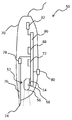
도 3은 코딩 패턴이 제공되는 물건의 개략도이다.
도 4는 디스플레이에 제거가능하게 부착되는 물건을 예시하는 개략도이다.
도 5a-f는 코딩 패턴의 개략도들이다.
도 6은 전자 펜을 개략적으로 예시하는 종단면이다.
도 7은 디스플레이를 통한 전자 디바이스와의 사용자 상호작용을 예시하는 개략도이다.1 is a schematic diagram of a system for providing user interaction with an electronic device.
2 is a schematic diagram of a display illustrating an array of pixels.
3 is a schematic diagram of an article provided with a coding pattern.
4 is a schematic diagram illustrating an object that is removably attached to a display.
5A-F are schematic diagrams of a coding pattern.
6 is a longitudinal cross-sectional view schematically illustrating the electronic pen.
7 is a schematic diagram illustrating user interaction with an electronic device via a display.
도 1을 참고하여, 전자 디바이스(10)와의 사용자 상호작용을 제공하기 위한 시스템이 간략하게 설명될 것이다. 전자 디바이스(10)는 프로세서(12)를 포함하며, 프로세서(12)는 사용자에게 출력을 제공하고 프로세서(12)에 의하여 프로세싱되는 정보의 결과들을 제시하기 위한 디스플레이(20)에 연결된다. 물건(30)은 디스플레이(20)에 고정식으로 또는 제거가능하게 부착된다. 물건(30)은 코딩 패턴(40)이 제공되는 표면(32)을 포함한다. 코딩 패턴(40)은 표면(32) 상의 정보를 코딩한다. 사용자는 코딩 패턴(40)을 판독할 수 있는 판독기(50)를 사용하여 프로세서(12)와 상호작용할 수 있다. 따라서 사용자는 디스플레이의 상이한 부분들에 판독기(50)를 포인팅할 수 있고, 그에 의해 코딩 패턴(40)의 상이한 부분들이 판독기(50)에 의하여 판독되게 트리거링된다. 이러한 방식으로, 판독기(50)는 코딩 패턴(40)에 의하여 인코딩되는 정보를 레코딩하고, 프로세서(12)에 대한 입력으로서 레코딩된 정보를 전송할 수 있다. 프로세서(12)는 레코딩된 정보를 프로세싱하고, 디스플레이(20) 상에 이미지를 업데이트함으로써 사용자에게 결과들을 제시할 수 있다.Referring to FIG. 1, a system for providing user interaction with an
코딩 패턴(40)이 제공되는 표면(32)은 코딩 패턴(40)을 통한 전자 디바이스(10)와의 사용자 상호작용을 허용하기 위해 임의의 종류의 디스플레이에 적용될 수 있다. 이런 이유로, 전자 디바이스(10)는 예컨대, 데스크탑 컴퓨터, 랩탑, 태블릿 PC, 또는 핸드헬드 PC와 같은 개인용 컴퓨터(PC), 이동 전화, 비디오 게임 콘솔, 스마트 TV, 또는 셀프-서비스 키오스크 또는 아케이드 머신과 같은 단말일 수 있다. 프로세서(12)는 통상적으로 전자 디바이스(10) 내에 배열된다. 프로세서(12)는 디스플레이(20) 상에 이미지를 출력하기 위하여 디스플레이(20)에 의해 정확하게 해석될 수 있는 신호를 생성하기 위한 디스플레이 제어기를 포함할 수 있다.
디스플레이(20)는 전자 디바이스(10) 및 프로세서(12)에 연결될 수 있는 개별 유닛일 수 있다. 디스플레이(20)는 예를 들어, 라디오 신호를 사용하는 무선 접속 또는 케이블을 통해 전자 디바이스(10)에 연결될 수 있다. 그러한 디스플레이(20)는 현재 디스플레이(20)에 연결되는 전자 디바이스(10)에 사용자 인터페이스를 제공하기 위하여 상이한 종류들의 전자 디바이스들(10)에 또한 연결가능할 수 있다. 그러한 디스플레이들(20)의 예들은, 음극선관 스크린들, 액정 디스플레이들 또는 플라즈마 디스플레이 패널들과 같은, 이미지들을 디스플레이하기 위해 임의의 타입의 기술을 사용하는 TV 스크린들 또는 컴퓨터 모니터들이다. 대안적으로, 디스플레이(20)는 단일 물리적 유닛에서 전자 디바이스(10)와 통합될 수 있다. 그러한 디스플레이들(20)의 예들에는 랩탑 스크린들, 또는 태블릿 PC, 핸드헬드 PC, 이동 전화, 비디오 게임 콘솔, 스마트 TV, 또는 셀프-서비스 키오스크 또는 아케이드 머신과 같은 단말의 디스플레이들이 있다.
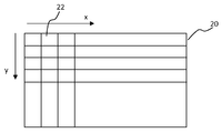
도 2에 도시된 바와 같이, 디스플레이(20)는 디스플레이(20) 상에 이미지를 생성하기 위하여 활성화되는 픽셀들(22)을 포함한다. 컬러 디스플레이에서, 각각의 픽셀(22)은 적색, 녹색 및 청색 컬러를 띄는 3개의 도트들을 포함할 수 있다. 픽셀들(22)은 픽셀들(22)의 어레이를 형성하는 디스플레이(20)의 전체 표면을 커버하도록 배열된다. 픽셀(22)의 사이즈 및 인접한 픽셀들(22) 간의 공간은 디스플레이(20)의 픽셀 피치를 규정하며, 여기서 픽셀(22)은 예를 들어, 각각 적색, 녹색 및 청색 컬러를 제공하는 서브-픽셀들을 포함할 수 있다. 어레이의 픽셀들(22)은 디스플레이 표면에 걸쳐 주기적인 구조를 형성한다. 이런 이유로, 픽셀 피치는 또한 디스플레이(20) 상에 픽셀들(22)의 공간 주파수를 규정한다.As shown in FIG. 2,
픽셀들(22)은 보통 디스플레이 표면 상에 수평 및/또는 수직 라인들로 배열된다. 따라서 픽셀들(22)의 어레이는 어레이 x-축 및 어레이 y-축을 규정할 수 있으며, 어레이 x-축 및 어레이 y-축은 각각, 디스플레이 표면의 수평 및 수직 방향을 따라 배열된다. 종종 서브픽셀들은 어레이 y-축을 따라 더 큰 연장부를 갖는 직사각형 형상을 갖는다. 서브픽셀들은 뿐만 아니라, 픽셀(22)이 전체적으로 정사각형 형상을 갖도록, 어레이 x-축을 따라 나란히(side-by-side) 배열될 수 있다.The
때때로 또한 도트 피치, 라인 피치, 스트라이프 피치 또는 형광체(phosphor) 피치로도 불리는 픽셀 피치는 상이한 디스플레이들(20) 간에 변화할 수 있다. 더 작은 픽셀 피치를 제공함으로써, 디스플레이(20)가 더 예리한 이미지를 생성하는 것이 가능할 수 있다. 또한, 사용자는 통상적으로 상이한 거리들을 두고 상이한 타입들의 디스플레이들(20)을 시청할 수 있다. 예컨대, 사용자는 통상적으로 컴퓨터 스크린보다 이동 전화의 디스플레이에 더 가까울 것이다. 이것은, 컴퓨터 스크린의 이미지 품질이 이동 전화 디스플레이의 이미지 품질보다 더 빠지는 것을 사용자가 경험하지 않게, 컴퓨터 스크린이 이동 전화 디스플레이보다 더 큰 픽셀 피치를 가질 수 있다는 것을 의미한다. 이런 이유로, 픽셀 피치는 디스플레이들(20)의 품질에 따라, 상이한 타입들의 디스플레이들(20) 간에 그리고 또한 동일한 타입의 디스플레이들(20) 간에 상당히 많이 변화한다.The pixel pitch, sometimes also referred to as dot pitch, line pitch, stripe pitch or phosphor pitch, can vary between
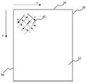
이제 도 3을 참고하여, 코딩 패턴(40)이 제공되는 물건(30)이 추가로 설명될 것이다. 물건(30)은 디스플레이(20)의 제조 동안에, 디스플레이(20)와 통합될 수 있고 디스플레이(20)에 부착될 수 있다. 대안에 따라, 물건(30)은 개별적으로 전달될 수 있으며, 디스플레이(20)에 부착될 수 있다. 물건(30)이 상이한 디스플레이들(20) 사이에서 이동될 수 있도록, 물건(30)은 디스플레이들(20)에 제거가능하게 부착될 수 있다.Referring now to FIG. 3, the
물건(30)은 가시 광에 대해 투과성인 시트 또는 막으로 형성될 수 있다. 이것은 물건(30)이 디스플레이(20)에 적용될 때, 물건(30)이 디스플레이된 이미지의 가시성에 영향을 미치지 않을 것임을 의미한다. 시트 또는 막의 두께는 물건(30)과 함께 사용될 디스플레이(20)의 타입이 무엇인지에 따라 변화할 수 있다. 물건(30)은 적절한 플라스틱 또는 유리 물질과 같은, 적절한 광학적 및 물리적 특징들을 갖는 적절한 물질로 형성될 수 있다.The
디스플레이(20)는 디스플레이 표면과의 터치 상호작용을 허용하기 위하여 예비되거나 이를 위해 예비되지 않을 수 있다. 디스플레이(20)가 터치 상호작용을 위해 예비되는 경우, 디스플레이를 터치하는데 있어 인가되는 압력이 디스플레이(20)를 손상시키지 않도록, 인가되는 압력을 분배할 수 있는 보호 시트가 디스플레이(20)에 제공될 수 있다. 그러나 디스플레이(20)가 터치 상호작용을 위해 예비되지 않는다면, 물건(30)은 터치되는 물건(30)에 의하여 손상되는 것으로부터 디스플레이(20)를 보호하도록 설계될 필요가 있을 수 있다. 그러한 경우들에 있어, 물건(30)은 더 큰 표면에 걸쳐 인가된 압력을 분배할 수 있는, 비교적 두꺼운 시트에 의하여 형성될 수 있다. 이런 이유로, 디스플레이(20)를 보호하기 위하여, 물건(30)은 통상적으로 수(a few) mm의 두께를 갖는 시트에 의하여 형성될 수 있다.
물건(30)은 디스플레이(20)에 대해 일정한 관계로 홀딩될 수 있다. 이것은 코딩 패턴(40)과 디스플레이 위치들 간의 관계가 시간에 따라 변화하지 않음을 의미한다. 디스플레이(20)에 대해 일정한 관계로 물건(30)을 홀딩하는 능력은 몇 개의(several) 인자들에 따라 좌우된다. 예컨대, 두껍고 강성인(rigid) 물건(30)을 제공함으로써, 물건(30)은 일단 디스플레이(20)에 장착되면 그 자리에 유지될 수 있다. 예컨대, 물건(30)이 대형 TV 스크린들과 함께 사용된다면, 큰 사이즈의 물건(30)이 필요할 수 있다. 이런 이유로, 물건(30)은 강성 물건(30)을 제공하기 위하여 1 mm 크기의 두께를 갖는 시트로 형성될 수 있다. 두꺼운 시트 물건(30)은 큰 사이즈의 물건(30)이 디스플레이(20)에 대해 일정한 관계로 단단히 홀딩되는 것을 가능하게 한다.The
반면에, 작은 사이즈의 물건(30)은 1 mm보다 훨씬 작은, 통상적으로 0.1-0.5 mm의 두께를 갖는 박막에 의하여 형성될 수 있다. 그러한 박막은 예를 들어, 이동 전화 디스플레이 또는 랩탑 스크린에 대해 일정한 관계로 물건(30)을 배열하기에 적합할 수 있다. 박막 물건(30)은 또한 물건(30)의 이송을 용이하게 하기 위하여 둘둘 말리기에(rolled up) 충분히 탄력적(elastic)일 수 있다. 이는, 물건(30)이 사용자에 의해 휴대될 수 있고 사용자가 디스플레이(20)와 상호작용할 수 있기를 원할 때, 임의의 디스플레이(20)에 부착될 수 있음을 의미한다.On the other hand, the small
물건(30)은 특정 사이즈의 디스플레이들(20)에 부착되도록 의도될 수 있다. 이것과 관련하여, 물건(30)은 물건(30)과 함께 사용될 디스플레이(20)와 대략 동일한 사이즈일 수 있다. 이것은, 물건(30)이 디스플레이(20)에 딱 맞도록(fit snugly) 디스플레이(20)에 대한 에지-대-에지 관계로 배열될 수 있다는 것을 의미한다. 그러나 물건(30)은 대안적으로 상이한 사이즈들의 디스플레이들(20)과 함께 사용되도록 의도될 수 있다. 그 후, 물건(30)이 디스플레이(20)의 에지들 중 적어도 하나의 에지의 외부로 돌출하도록, 물건(30)이 디스플레이(20)에 부착될 수 있다. 디스플레이(20)의 해당 특정 부분과의 상호작용을 제공하기 위하여 물건(30)이 디스플레이(20)의 단지 일부만을 커버하는 것이 또한 고려될 수 있다. 물건(30)은 대부분의 디스플레이들(20)의 형상에 맞도록 직사각형일 수 있다.The
물건(30)의 하나 또는 그 초과의 부분들에는 물건(30)이 디스플레이(20)에 부착되도록 허용하는 접착제(adhesive material)가 제공될 수 있다. 대안적으로, 물건(30)은 디스플레이(20)에 적용될 때, 그것이 디스플레이 표면에 달라붙도록, 끈적한 표면을 가질 수 있다. 추가적 대안으로서, 물건(30) 및 디스플레이(20)에는 Velcro® 파스너(fastener)들과 같은 후크-앤드-루프(hook-and-loop) 파스너들의 대응하는 하나 또는 그 초과의 패치(patch)들이 제공될 수 있다. 또 다른 대안으로서, 물건(30)에는 디스플레이(20)의 에지를 수용하기 위한 클립이 제공될 수 있다. 물론, 디스플레이(20)에는 접착제 또는 클립과 같은 것에 대신하여 또는 이들 분 아니라, 물건(30)이 디스플레이(20)에 부착되게 하기 위한 수단이 제공될 수 있다.One or more portions of the
또 다른 대안으로서, 물건(30)을 디스플레이(20)에 부착하기 위한 개별적 파스너가 제공될 수 있다. 이것은, 물건(30)이 디스플레이(20)에 적용되기 이전에 물건(30) 또는 디스플레이(20) 중 하나에 부착되는 양면 테잎으로서 달성될 수 있다. 도 4에 예시되는 일 실시예에서, 홀더 어셈블리(60)가 제공된다. 홀더 어셈블리(60)는 예를 들어, 나사들에 의하여 디스플레이(20)에 단단히 부착될 수 있는 프레임(62)을 포함할 수 있다. 홀더 어셈블리(60)는 또한 프레임(62) 상에 장착될 수 있는, 협력 암(cooperating arm)들(64)의 쌍들 또는 하나 또는 그 초과의 클립들을 포함할 수 있다. 물건(30)을 디스플레이(20)에 장착 시, 물건(30)은 디스플레이(20)에 관하여 물건(30)의 위치를 고정시킬, 협력 암들(64)의 쌍들 또는 클립들에 끼워 맞춰진다(fitted).As another alternative, a separate fastener may be provided for attaching the
물건(30)은 코딩 패턴(40)이 제공될 수 있는 표면(32)을 제공한다. 표면(32)이 디스플레이(20)에 대면하여 배열되도록, 물건(30)은 디스플레이(20)에 부착되게 배열될 수 있다. 대안적으로, 표면(32)은 보호 층에 의하여 커버될 수 있다. 이것은, 코딩 패턴(40)이 배열되는 표면(32)과 사용자가 직접 상호작용하지 않을 것임을 의미한다. 이런 이유로, 예를 들어, 판독기(50)를 사용하여 물건을 터치하는 것에 의한 사용자 상호작용이 코딩 패턴(40)을 마모시키지 않도록, 표면(32)은 보호된다.The
물건(30)의 표면(32)은 표면 x-축 및 표면 y-축을 규정하는 에지들(34, 36)에 의하여 제한될 수 있다. 상기 설명된 바와 같이, 물건(30)은 디스플레이들(20)의 가장 흔한 형상에 대응하도록 직사각형일 수 있다. 그러한 경우에, 에지들(34, 36)은 서로에 대해 직각일 수 있으며, 이런 이유로, 표면 x-축 및 표면 y-축은 서로에 직각일 것이다.
코딩 패턴(40)은 정보의 그래픽 코딩을 제공할 수 있다. 이것과 관련하여, 코딩 패턴(40)은 그리드에 따라 배열되는 마크들을 포함할 수 있으며, 여기서 마크들의 배치 및/또는 모폴로지(morphology)로 정보가 코딩된다.
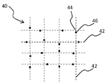
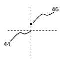
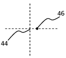
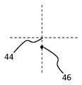
도 5a에 예시된 일 실시예에서, 코딩 패턴(40)은 가상 그리드 라인들(42)을 포함하며, 상기 가상 그리드 라인들(42)은 그들이 실제로 표면(32) 상에 제시되지 않을 수 있기 때문에 가상으로 불린다. 그러므로 그리드 라인들(42)은 도 5a에서 점선들에 의해 마킹된다. 가상 그리드 라인들(42)은 직교 그리드를 형성하게 서로 직각일 수 있다. 가상 그리드 라인들(42)은 그리드 교차점들(44)에서 교차하며, 여기서 그리드 교차점들(44)은 공칭점들을 형성한다. 코딩 패턴(40)의 정보는 마크(46)에 의하여 코딩될 수 있으며, 상기 마크(46)는 자신의 공칭점(44)에 대해 변위된다. 공칭점(44)으로부터의 마크(46)의 변위의 방향은 마크(46)에 의하여 코딩되는 값을 결정한다. 예컨대, 마크(46)는 도 5b-e에 예시되는 바와 같이, 4개의 상이한 방향들 중 하나의 방향으로 변위되도록 허용될 수 있다. 그 후, 각각의 마크(46)는 정보의 2개 비트들을 코딩할 것이다. 마크들(46)은 도 5b-e에 예시되는 바와 같은 가상 그리드 라인들(42) 중 하나를 따라 변위될 수 있다. 이 타입의 코딩 패턴(40)은 US 6,663,008에 추가로 설명되며, 상기 미국 출원은 이로써 인용으로 포함된다.In one embodiment illustrated in FIG. 5A, the
마크들은 또한 그리드 교차점들(44)에 또는 그리드 교차점들(44) 중 일부에 제공될 수 있다. 이것은 가상 그리드 라인들(42)을 검출하는데 도움을 줄 수 있고, 이에 따라 코딩 패턴(40)의 디코딩을 가능하게 할 수 있다. 더욱이, 각각의 그리드 교차점(44)은 정보를 코딩하기 위하여 마크(46)와 연관될 필요가 없다. 일 실시예에서, 그리드 라인들(42)을 표시하기 위한 마크가 제공되는 그리드 교차점들(44)은 정보를 코딩하기 위한 연관된 마크(46)를 갖지 않는 반면, 그리드 라인들을 표시하기 위한 마크가 제공되지 않는 그리드 교차점들(44)은 정보를 코딩하기 위한 마크(46)와 연관된다.Marks may also be provided at
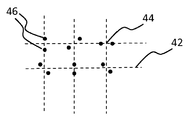
몇몇 공칭점들(44) 또는 각각의 공칭점(44)은 정보를 코딩하기 위한 다수의 마크들(46)과 연관될 수 있다. 이것은 하나의 공칭점(44)에 관해 추가적 정보를 코딩하기 위하여 사용될 수 있다. 도 5f에 예시되는 일 실시예에서, 공칭점(44)은 마크들(46)의 쌍과 연관되며, 마크들(46)의 쌍의 무게 중심(center of gravity)이 공칭점(44)에 있도록, 마크들(46)의 쌍은 공칭점(44)의 대향 면들 상에 배열된다. 이것은 가상 그리드 라인들(42)의 검출을 가능하게 한다.Some
마크들(46)은 정사각형들, 삼각형들, 또는 임의의 다른 단순한 형상에 의해 형성될 수 있다. 일 실시예에서, 마크들(46)은 프린팅하기에 쉬울 수 있는 원형 도트들에 의해 형성된다. 다른 실시예에서, 마크들(46)은 비대칭 형상을 갖는 도트들에 의해 형성된다. 도트들은 예를 들어, 타원형 또는 직사각형일 수 있다. 대안적으로, 마크들(46)은 상이한 형상들을 가질 수 있으며, 여기서 마크(46)의 형상은 코딩 패턴(40)의 정보의 코딩에 기여할 수 있다.
마크들(46)은 적외선 방사를 산란식으로 반사하도록 배열될 수 있다. 이것은 마크들(46)의 검출을 가능하게 할 수 있는데, 이는 다수의 디스플레이들(20)이 적외선 필터를 포함하며, 이에 따라 적외선 방사가 디스플레이(20)로부터 방출되지 않기 때문이다. 판독기(50)는 적외선 방사를 검출하도록 배열될 수 있으며, 적외선 방사를 방출하는 광원과 조합되는 경우, 적외선 반사성 마크들(46)은 판독기(50)에서 어두운 배경 상에 밝은 스팟(spot)들로서 나타날 것이다.
그러나 마크들(46)은 대안적으로 마크들(46)이 표면의 이미지에서 검출되도록 허용하기 위하여, 입사 방사의 정반사, 회절, 굴절, 흡수, 내부 전반사, 또는 브래그 반사를 제공하도록 배열될 수 있다.However, the
디스플레이(20)로부터의 방사가 코딩 패턴(40)의 검출에 간섭하지 않도록 보장하기 위하여, 물건(30)에는 적외선 필터 층이 제공될 수 있다. 이 적외선 필터 층은 그것이 코딩 패턴(40)과 판독기(50) 사이에 있지 않도록, 디스플레이(20)에 대면하게 배열될 것이다.In order to ensure that radiation from the
적외선 반사성 마크들(46)은 적외선 방사 및 가시적 방사 양자 모두를 산란식으로 반사하는 화이트(white) 마크들로서 용이하게 달성될 수 있다. 이것은 코딩 패턴(40)이 사용자에게 가시적일 것임을 의미한다. 그러나 코딩 패턴(40)은 코딩 패턴(40)이 단지 디스플레이된 이미지의 콘트라스트에 있어 약간의 저하로서 경험될 정도의 작은 마크들에 의해 형성될 수 있다.Infrared
코딩 패턴(40)은 위치들을 코딩하도록 배열되는 위치-코딩 패턴일 수 있다. 일 실시예에서, 다수의 마크들(46)의 셀은 다른 물건들로부터 물건(30)을 구분하기 위하여 사용될 수 있는 하나의 위치 그리고 가능하게는 또한 식별자를 코딩하기 위하여 사용될 수 있다. 그러한 셀들은 표면(32)에 걸친 위치들을 코딩하기 위하여 표면(32)에 걸쳐 나란히 배열될 수 있다. 예를 들어, US 6,663,008에 설명된 바와 같이, 다른 실시예에서, 위치-코딩 패턴은 윈도잉(windowing) 특성을 가지며, 이는 미리 결정된 사이즈의 각각의 부분이 위치 코드 내에서 고유하고, 따라서 위치-코딩 패턴의 확실한 위치를 코딩함을 의미한다. 각각의 위치는 도트들과 같은 다수의 간단한 심볼들에 의하여 코딩될 수 있고, 제1 위치를 코딩하기 위하여 사용되는 다수의 심볼들 중 적어도 몇몇은 제2 인접 위치의 코딩에 또한 기여한다.
위치-코딩 패턴은 예를 들어, 하나의 위치를 코딩하기 위하여 6 x 6 마크들(46)을 사용할 수 있다. 이것은 위치-코딩 패턴의 상이한 부분들이 상이한 물건들(30) 상에 배열될 수 있도록, 매우 넓은 영역에서의 위치들의 코딩을 가능하게 한다. 이런 이유로, 물건(30)을 식별하기 위한 코딩된 식별자를 사용하는 대신, 각각의 물건(30)이 위치들의 상이한 범위들을 코딩하도록 배열될 수 있음에 따라, 레코딩된 위치가 물건(30)을 식별할 수 있다. 이것은 물건(30) 상의 위치-코딩 패턴(40)이 넓은 영역 내의 절대(absolute) 위치들을 코딩할 수 있음을 의미한다. 이런 이유로, 영역의 좌표들의 원점(origin)이 물건(30) 자체에 대해 인코딩될 필요가 없다. 절대 위치들은 위치-코딩 패턴에 의하여 인코딩되는 넓은 영역의 서브세트 내에 국부적 위치들로 변환될 수 있다. 서브세트는 물건 표면(32)에 대응하는 영역 내에 위치들을 인코딩할 수 있다. 이것은 절대 위치들을 물건 표면(32) 상의 국부적 위치로서 해석하는 것을 가능하게 할 수 있다.The location-coding pattern may use 6 x 6 marks 46 to code one location, for example. This allows coding of positions in a very wide area so that different parts of the position-coding pattern can be arranged on
그러나 그러한 큰 위치-코딩 패턴을 사용하는 것은 필수적이지 않을 수 있다. 다른 실시예에서, 더 적은 마크들(46)이 하나의 위치를 코딩하기 위하여 사용된다. 이것은 위치의 디코딩을 더 빠르게 할 수 있다.However, using such a large location-coding pattern may not be necessary. In another embodiment,
추가적 실시예에서, 마크들(46)은 표면(32)에 걸쳐 규칙적으로 배치된다. 마크들(46)은 정보를 코딩하기 위하여 상이한 형상들 또는 컬러들을 가질 수 있다. 각각의 마크(46)는 많은 양의 정보의 코딩을 가능하게 하기 위하여 복합 구조를 가질 수 있다. 이런 이유로, 표면(32) 상의 위치는 단일 마크(46)에 의하여 코딩될 수 있다.In a further embodiment, the
코딩 패턴(40)은 표면(32)에 걸쳐 주기적인 구조를 형성할 수 있다. 코딩 패턴(40)은 그리드에 따라 배열되는 마크들(46)을 포함할 수 있으며, 여기서 그리드는 표면 상의 마크들(46)의 주기성을 규정한다. 코딩 패턴(40)의 그리드 사이즈는 코딩 패턴(40)의 2개의 인접한 그리드 라인들(42) 간의 거리로서 규정될 수 있다. 코딩 패턴(40)의 그리드 사이즈는 또한 표면(32) 상의 마크들(46)의 공간 주파수를 규정한다. 개별 마크들(46)이 그리드 교차점들(44)로부터 상이한 방향들로 변위되더라도, 마크들(46)의 공간 주파수는 그리드 사이즈에 의하여 주어질 것이다. 그리드는 또한 그리드 x-축 및 그리드 y-축을 규정할 수 있으며, 그리드 x-축 및 그리드 y-축은 코딩 패턴(40)의 가상 그리드 라인들(42)과 일치한다.
상기 설명된 바와 같이, 픽셀 피치는 디스플레이(20) 상의 픽셀들(22)의 공간 주파수를 규정한다. 더욱이, 디스플레이(20)는 표면(32) 상의 마크들(46)의 공간 주파수를 규정하는 그리드 사이즈를 갖는 그리드에 따라 배열된 마크들(46)에 의해 덮어씌워진다. 이것은, 겹쳐지는 방식으로 배열되는 2개의 주기적 구조들이 존재함을 의미하며, 여기서 2개의 주기적 구조들은 다수의 공간 주파수들을 포함한다. 이런 이유로, 2개의 주기적 구조들의 공간 주파수들의 컨볼루션(convolution)은 다른 결과적 주파수들을 형성할 수 있다. 결과 주파수가 인간에 의해 인지가능한 주파수들 내에 있다면, 즉, 주파수가 상당히 작다면, 사용자는 디스플레이(20) 상에서 무아레 패턴을 볼 수 있다. 무아레 패턴은 매우 독특하고, 디스플레이된 이미지의 가시성에 심각하게 영향을 미칠 수 있다.As described above, the pixel pitch defines the spatial frequency of the
따라서 가시적 무아레 패턴이 디스플레이(20) 상에 형성되지 않음을 보장하는 것이 바람직하다. 무아레 패턴이 형성되지 않음을 보장하는 하나의 방법은 코딩 패턴(40)의 그리드 사이즈가 디스플레이(20)의 픽셀 피치에 적용되는 것을 보장하는 것이다. 그러나 코딩 패턴(40)은 대안적으로, 그리드 x-축이 어레이 x-축에 대해 소정 각도만큼 오프셋되도록, 디스플레이(20)에 대해 회전될 수 있다. 코딩 패턴(40)의 회전은 가시적 무아레 패턴이 발생할 확률이 낮도록, 픽셀들(22)의 어레이와 코딩 패턴(40)의 그리드 간의 관계를 제공할 수 있다.Thus, it is desirable to ensure that no visible moire pattern is formed on the
코딩 패턴(40)의 회전으로 인해, 디스플레이(20)의 픽셀 피치가 코딩 패턴(40)의 그리드 사이즈와 호환되는지 여부를 고려할 필요가 전혀 없이, 동일한 물건(30)이 상이한 디스플레이들(20)과 함께 사용될 수 있다. 이것은 상이한 디스플레이들(20)과 함께 사용될 수 있는 휴대용 물건(30)의 제조를 가능하게 한다.Due to the rotation of the
또한, 동일한 그리드 사이즈의 코딩 패턴(40)이 항상 사용될 수 있다. 이것은 코딩 패턴(40)을 판독하기 위한 판독기(50)가 특정 그리드 사이즈를 갖는 코딩 패턴(40)을 판독하기 위하여 조정되고 최적화될 수 있음을 의미한다. 더욱이, 코딩 패턴(40)이 어떠한 타입의 디스플레이(20)에 적용되는지와 무관하게, 코딩 패턴(40)을 판독하기 위하여 동일한 판독기(50)가 사용될 수 있다.Also,
뿐만 아니라, 코딩 패턴(40)이 디스플레이(20)의 제조 동안에 디스플레이(20)에 고정식으로 장착되는 물건(30) 상에 배열될지라도, 디스플레이(20)에 대해 회전되는 코딩 패턴(40)을 사용하는 것이 유리할 수 있다. 그러한 상황에서, 코딩 패턴(40)이 겹쳐질 디스플레이(20)의 픽셀 피치가 알려지고, 이로 인해, 코딩 패턴(40)의 그리드 사이즈를 이 픽셀 피치에 맞추는 것이 가능하다. 예컨대, 그리드 사이즈는 정수배 픽셀 피치와 동일하게 설정될 수 있다. 그러나 그리드 사이즈는 무아레 효과들을 일으키지 않기 위해 원하는 값에 매우 근접하게(closely) 충족시킬 필요가 있다. 그러므로 디스플레이(20)의 픽셀 피치에 코딩 패턴(40)의 그리드 사이즈를 맞추는 것은 제조 정확성에 대해 엄격한(harsh) 요건들을 부과할 수 있다. 이런 이유로, 생산 면에서의 수율은 디스플레이(20)에 대해 코딩 패턴(40)을 회전시킴으로써 향상될 수 있다.In addition, although the
그리드 x-축이 어레이 x-축에 대하여 소정 각도만큼 오프셋되게 하는 디스플레이(20)에 대한 코딩 패턴(40)의 회전은, 물건 표면(32)의 표면 x-축에 대해 코딩 패턴(40)을 회전시킴으로써 달성될 수 있다. 상기 논의된 바와 같이, 물건(30)은 디스플레이(20)에 맞추어 조정되도록 배열될 수 있다. 그러므로 그리드 x-축이 물건(30)의 표면 x-축에 대해 소정 각도만큼 오프셋되는 경우, 물건(30)이 디스플레이(20)에 부착될 때, 그리드 x-축은 유사하게 디스플레이(20)의 어레이 x-축에 대해 소정 각도만큼 오프셋될 것이다.Rotation of the
가상 그리드 라인들(42)은 직교 그리드를 형성하도록 배열될 필요가 없다. 하나의 대안에서, 마름모꼴 그리드가 서로에 대해 60°의 각도로 배열되는 가상 그리드 라인들(42)로 형성될 수 있다. 추가적 대안들에서, 가상 그리드 라인들(42)은 삼각형 또는 육각형 그리드를 형성할 수 있다. 그러한 경우들에 있어서, 그리드 y-축은 그리드 x-축이 어레이 x-축과 관련되는 것과 동일한 방식으로 어레이 y-축과 관련되지 않을 것이다. 그러나 그리드 y-축이 또한 어레이 y-축에 관하여 적절한 각도만큼 오프셋되는 한, 가시적 무아레 간섭은 그리드 x-축을 어레이 x-축에 관하여 소정 각도만큼 오프셋되도록 배열함으로써 여전히 방지될 수 있다. 이것은, 가능한 각도들의 범위가 가상 그리드 라인들(42)의 비-직교 구성들에 대해 상이하다는 것을 의미한다.
물건(30)은 특정 타입들의 디스플레이들(20)과 함께 사용되도록 정해질 수 있다. 물건(30)의 제조 이전에, 물건(30)과 함께 사용될 디스플레이들(20)의 상이한 픽셀 피치들의 범위가 결정될 수 있다. 더욱이, 사용될 코딩 패턴(40)의 그리드 사이즈가 설정될 수 있다. 일 실시예에서, 그리드 사이즈는 대략 300 ㎛이다. 물론, 다른 그리드 사이즈들이 마찬가지로 사용될 수 있다. 예컨대, 그리드 사이즈는 100 ㎛-2 mm 범위일 수 있다. 세트 그리드 사이즈 및 알려진 범위의 픽셀 피치들을 사용하여, 그리드 x-축과 어레이 x-축 사이에서 상이한 각도들의 효과가 분석될 수 있다. Isaac Amidror 저자의 The Theory of the Moire Phenomenon, Volume 1: Periodic Layers 챕터 3에 설명된 바와 같이, 가시적 무아레 간섭을 일으킬 각도들을 식별하기 위하여 2개의 겹쳐진 주파수들 간의 관계들이 분석될 수 있다.The
그리드 x-축과 어레이 x-축 사이의 상이한 각도들의 효과를 분석하면, 무아레 문제들을 야기하지 않는 각도들이 결정될 수 있다. 이런 이유로, 무아레 효과가 가시적이 되지 않을 범위 내에서 허용가능한 범위의 각도들이 발견될 수 있다. 코딩 패턴(40)은 그 후, 그리드 x-축이 허용가능한 범위 내의 표면 x-축에 대해 소정 각도를 형성하도록, 물건(30)에 적용될 수 있다. 이것은 어레이 x-축에 대한 그리드 x-축의 각도의 작은 변화는 무아레 효과를 도입하지 않을 것이기 때문에, 디스플레이(20)에 물건(30)을 장착하는 데 있어 공차(tolerance)가 허용될 수 있음을 의미한다.By analyzing the effects of different angles between the grid x-axis and the array x-axis, angles that do not cause moire problems can be determined. For this reason, an acceptable range of angles can be found within a range in which the moire effect will not be visible.
예를 들어, 물건(30)은 컴퓨터 모니터와 함께 사용되도록 의도될 수 있다. 19 인치의 스크린 사이즈 및 1280 x 1024 픽셀들의 해상도를 갖는 컴퓨터 모니터는 0.208 mm의 픽셀 피치를 갖는다. 0.300 mm의 그리드 사이즈를 갖는 물건(30)이 이 컴퓨터 스크린과 함께 사용될 것이라면, 그리드 x-축은 가시적 무아레 간섭을 방지하기 위하여 어레이 x-축에 대해 10-35° 범위의 각도만큼 오프셋될 수 있다. 다른 물건(30)이 TV 스크린과 함께 사용되도록 의도될 수 있다. 42 인치의 스크린 사이즈 및 1920 x 1080 픽셀들의 해상도를 갖는 TV 스크린은 0.342 mm의 픽셀 피치를 갖는다. 이 예에서, 0.300 mm의 그리드 사이즈를 갖는 물건(30)이 이 컴퓨터 스크린과 함께 사용될 것이라면, 그리드 x-축은 가시적 무아레 간섭을 방지하기 위하여 어레이 x-축에 대해 30-40° 범위의 각도만큼 오프셋될 수 있다.For example, object 30 may be intended for use with a computer monitor. A computer monitor with a screen size of 19 inches and a resolution of 1280 x 1024 pixels has a pixel pitch of 0.208 mm. If an
다른 대안에 따라, 그리드 x-축과 표면 x-축 사이의 적절한 각도는 사용될 픽셀 피치들에 관한 그리드 사이즈의 특정한 분석을 수행하지 않고 선택될 수 있다. 일 실시예에서, 그리드 x-축은 물건(30)의 표면 x-축에 대해 10-15°의 각도만큼 오프셋되도록 배열될 수 있다. 다른 실시예에서, 그리드 x-축은 물건(30)의 표면 x-축에 대해 25-35°의 각도만큼 오프셋되도록 배열될 수 있다. 이들 실시예들 양자 모두에 있어서, 무아레 효과가 관찰되지 않도록, 디스플레이(20)의 픽셀들(22)의 어레이와 코딩 패턴(40)의 그리드 간의 관계가 제공될 수 있다. 또 다른 실시예에서, 그리드 x-축은 물건의 표면 x-축에 대해 대략 45°, 예컨대 40-50°의 각도만큼 오프셋되도록 배열될 수 있다. 디스플레이(20)의 픽셀들(22)의 어레이와 코딩 패턴(40)의 그리드 간의 이 관계는 가시적 무아레 간섭들이 방지될 수 있는 시스템을 초래하는 것으로 또한 밝혀졌다.According to another alternative, the appropriate angle between the grid x-axis and the surface x-axis can be selected without performing a particular analysis of the grid size with respect to the pixel pitches to be used. In one embodiment, the grid x-axis may be arranged to be offset by an angle of 10-15 ° with respect to the surface x-axis of the
물건 표면(32) 상의 코딩 패턴(40)의 배열은 또한 물건(30)의 표면 x-축과 디스플레이(20)의 어레이 x-축 간의 관계를 고려할 수 있음이 인식되어야 한다. 몇몇 환경들에서, 물건(30)이 디스플레이(20)에 대하여 장착될 방식이 상당히 정확히 알려질 수 있다. 이것은 예를 들어, 물건(30)이 디스플레이(20)의 제조 동안에 디스플레이(20)에 통합되는 경우, 또는 디스플레이(20)에 대한 물건(30)의 부착이 홀더(60)에 의하여 정확하게 제어되는 경우일 수 있다. 그러한 경우들에 있어서, 그리드 x-축과 어레이 x-축 간의 최종적 관계가 잘 알려질 수 있다. 이런 이유로, 그리드 x-축이 허용가능한 범위 내에서 어레이 x-축에 대한 소정 각도를 형성하도록, 코딩 패턴(40)이 물건(30)에 적용될 수 있다.It should be appreciated that the arrangement of the
마크들(46)의 사이즈는 디스플레이(20)의 서브-픽셀보다 상당히 더 작을 수 있다. 이것은 마크(46)가 전체 서브-픽셀을 커버하지 않을 것임을 의미하며, 마크(46)가 전체 서브-픽셀을 커버하지 않는 경우 디스플레이(20) 상에서는 짜증스러운 컬러의 이동이 발생할 수 있다. 따라서 마크들(46)의 사이즈는 디스플레이(20)의 컬러들에 대한 간섭을 방지하기 위하여 가능한 한 작으면서, 마크들(46)의 검출을 가능하게 하기 위하여 가능한 한 커야만 한다.The size of the
주어진 물건에 대해, 모든 마크들(46)은 바람직하게 동일하거나 또는 거의 동일한 사이즈를 갖는다. 마크들(46)이 10 ㎛보다 더 작은 직경을 갖는다면, 마크들(46)은 검출하기에 어려울 수 있는 반면, 마크들(46)이 110 ㎛보다 더 큰 직경을 갖는다면, 마크들(46)은 디스플레이(20)의 컬러들에 간섭할 수 있다. 마크들(46)을 검출하는 어려움은 마크들(46)이 입사 방사와 상호작용하는 방식에 따라 좌우될 수 있다. 예컨대, 마크들(46)이 산란식으로 방사를 반사하도록 배열되는 경우, 마크들(46)은 60-80 ㎛, 또는 80-110 ㎛ 범위의 직경을 가질 수 있다. 마크들(46)이 방사를 전반사하도록 배열되는 경우, 마크들(46)은 10-40 ㎛ 범위의 직경을 갖도록 배열될 수 있다. 더 작은 직경을 갖도록 마크들(46)을 배열함으로써, 물건(30)은 디스플레이(20)의 컬러들에 대한 간섭을 야기하지 않고 다수의 상이한 타입들의 디스플레이들(20)과 함께 사용될 수 있다.For a given object, all marks 46 preferably have the same or nearly the same size. If the
마크들(46)의 사이즈는 물건(30)과 함께 사용되도록 의도되는 디스플레이들(20)의 타입들에 의존하여 선택될 수 있다.The size of the
일 실시예에서, 마크들(46)은 비대칭 형상을 갖도록 배열된다. 마크들(46)은, 마크들(46)이 서브픽셀들의 긴 면에 걸치는 것보다 서브픽셀의 짧은 면에 걸쳐 더 큰 연장부를 갖도록, 디스플레이의 서브픽셀들에 관하여 배열될 수 있다. 이것은, 마크들(46)이 단지 서브픽셀의 긴 면의 일부분(fraction)에 걸쳐서만 연장되는 한편 서브픽셀의 짧은 면에는 완전히 걸쳐 연장되도록 배열될 수 있음을 의미한다. 그러한 비대칭 마크(46)는 개별적 서브픽셀의 더 작은 부분을 커버하면서 원형 도트와 동일한 면적을 가질 수 있다. 대신에, 비대칭 마크(46)는 적어도 2개의 인접한 서브픽셀들과 중첩하도록 배열될 수 있다. 이것은, 디스플레이(20) 상의 경험 컬러에서의 이동이 방지될 수 있음을 의미한다.In one embodiment, the
특정 디스플레이의 서브픽셀들은 어레이 x-축을 따라 80 ㎛ 연장되고, 어레이 y-축을 따라 240 ㎛ 연장될 수 있다. 그러한 일 실시예에 대해, 마크들(46)은 어레이 x-축을 따라 연장되는 140 ㎛의 장축 및 어레이 y-축을 따라 연장되는 70 ㎛의 단축을 갖는 타원형 도트들로서 배열될 수 있다.Subpixels of a particular display may extend 80 μm along the array x-axis and 240 μm along the array y-axis. For one such embodiment, the
마크들(46)은 그리드를 따라 배열되더라도, ― 여기서 그리드 x-축은 표면 x-축에 대해 소정 각도만큼 오프셋됨 ― 비대칭 마크들(46)은 표면 x-축에 맞추어 조정되는 더 긴 면을 가질 수 있음이 유념되어야 한다. 이것은, 디스플레이(20) 상에 물건(30)이 배열될 때, 마크들(46)의 더 긴 면이 어레이 x-축에 맞추어 조정될 것임을 의미한다. 예컨대, 이와 같이 타원형 도트들의 장축은 어레이 x-축에 맞추어 조정될 것이다.Although the
마크들(46)이 그리드 교차점들(44)로부터 변위될 때, 변위는 디스플레이(20)의 픽셀들에 대한 국부적 가시적 간섭을 야기할 수 있다. 이런 이유로, 그리드 x-축이 그리드 사이즈와 픽셀 피치 간의 가시적 무아레 간섭을 방지하기 위하여 디스플레이(20)의 픽셀들의 어레이에 대해 소정 각도만큼 오프셋된다 하더라도, 국부적 간섭이 그리드 교차점(44)으로부터의 마크(46)의 변위에 의하여 야기될 수 있다. 마크들(46)의 변위가 디스플레이의 사용자 경험에 영향을 미치는 것을 방지하기 위하여, 변위의 사이즈가 가능한 한 작게 배열될 수 있다.When the
일 실시예에서, 그리드 교차점(44)으로부터의 마크(46)의 변위는 50 ㎛보다 작은데, 바람직하게는 10-30 ㎛ 범위이다. 이것은, 그리드 교차점(44)으로부터의 마크(46)의 변위가 디스플레이(20)에 대한 가시적 국부적 간섭을 야기하지 않음을 의미할 수 있다.In one embodiment, the displacement of
그리드 교차점(44)으로부터의 마크(46)의 변위는 마크(46)가 그리드 교차점(44)으로부터 변위되는 방향의 검출을 가능하게 하도록 충분히 커야 한다. 일 실시예에서, 그리드 교차점(44)으로부터의 마크(46)의 변위는 마크(46)의 직경의 대략 50%이며, 이는 변위의 방향이 검출될 수 있도록 보장할 수 있다.The displacement of the
물건(30)은 디스플레이(20)의 픽셀들의 어레이에 근접하게(in close vicinity) 배열될 수 있다. 이것은, 사용자가 디스플레이(20)에 대한 시청 각도를 변화시킴에 따라, 사용자가 물건(30) 상의 마크들(46)이 픽셀들에 관하여 움직이는 것을 알아채는 것(또한 시차(parallax) 현상으로서 알려짐)을 방지할 수 있다. 그러나 물건(30)이 디스플레이(20)의 픽셀들의 어레이에 밀접한 관계로(in close relation to) 배열될 때, 마크들(46)과 픽셀들 간의 간섭의 국부적 효과들은 더욱 명확하게 가시화될 수 있다. 이런 이유로, 물건(30)이 디스플레이(20)의 픽셀들의 어레이에 밀접한 관계로 배열될 때, 그리드 교차점들(44)로부터의 마크들(46)의 변위 및 마크들(46)의 사이즈가 가시적인 국부적 간섭 문제들을 방지하기 위하여 가능한 한 작다는 것이 훨씬 더 중요하다. 대안적으로, 국부적 간섭 문제들은 디스플레이(20)의 픽셀들의 어레이로부터 떨어진 소정 거리에 장착되도록 물건(30)을 배열함으로써 방지될 수 있다.The
이제 도 6을 참고하여, 코딩 패턴(40)을 판독하기 위한 판독기(50)가 설명될 것이다. 판독기(50)는 2-차원 이미지를 획득하도록 배열되는, 광학적 이미지 센서(54), 예컨대, 전하 결합 소자(CCD) 또는 상보형 금속 산화물 반도체(CMOS) 센서 위에 물건(32)의 이미지를 형성하기 위한 광학 시스템(52)을 포함할 수 있다. 광학 시스템(52)은 센서 표면 위에 이미지를 포커싱하기 위한 렌즈(56)를 포함할 수 있다. 광학 시스템(52)은 광을 광학적 이미지 센서(54)로 가이딩하기 위한 하나 또는 그 초과의 미러들을 포함할 수 있는 광 가이드(58)를 또한 포함할 수 있다. 또한, 광학 시스템(52)은 원치않는 파장들을 필터링하기 위한 파장 필터를 포함할 수 있다. 상기 설명된 바와 같이, 코딩 패턴(40)은 적외선 반사성 마크들(46)에 의하여 형성될 수 있다. 단지 적외선 방사만이 광학적 이미지 센서 표면에 도달하게 함으로써, 광학적 이미지 센서(54)에 의하여 포착되는 이미지에서의 신호 대 잡음비가 개선된다.Referring now to FIG. 6, a
판독기(50)는 광원(미도시)을 추가로 포함할 수 있다. 광원은 이미지화되는 표면(32)의 부분을 향해 광을 방출할 수 있다. 따라서, 이미지화 조건들이 개선될 수 있다. 광원은, 코딩 패턴(40)이 확실한(strong) 방식으로 상호작용할 적외선 방사를 방출하도록 추가로 배열될 수 있다.
판독기(50)는 도 6에 예시되는 바와 같이 전자 펜(70)으로서 형성될 수 있다. 전자 펜(70)은 전자 펜(70)의 모든 컴포넌트들이 내부에 장착되는 펜-타입 케이싱(casing)을 가질 수 있다.The
전자 펜(70)은 광학적 이미지 센서(54)에 의하여 레코딩되는 이미지에 기반하여 코딩 패턴(40)을 디코딩하도록 배열될 수 있는 분석 유닛(72)을 추가로 포함할 수 있다. 일 실시예에서, 광학적 이미지 센서(54)는 표면(32) 상에 위치-코딩 패턴을 묘사하고, 분석 유닛(72)은 전자 펜(70)의 위치를 디코딩하도록 배열된다. 분석 유닛(72)은 레코딩되는 이미지에 대한 전자 펜(70)의 위치를 직접 결정하기 위하여 광학적 이미지 센서(54)와 통합될 수 있다. 예를 들어, 분석 유닛(72)은 광학적 이미지 센서(54)를 또한 홀딩할 수 있는, 용도에 맞게 적응되는 고객-특정 집적 회로(예를 들어, ASIC(application-specific integrated circuit))로서 실현될 수 있다. 대안으로서, 분석 유닛(72)은 광학적 이미지 센서(54)로부터 레코딩된 이미지들을 수신하도록 배열될 수 있다. 분석 유닛(72)은 그 후 고객-특정 집적 회로로서, 또는 프로그램가능 집적 회로(예를 들어, PROM(Programmable Read-Only Memory), FPGA(Field-Programmable Gate Array)), 또는 획득된 위치 데이터에 기반하여 위치를 결정하기 위하여 특정 소프트웨어 프로그램을 실행시키는 일반적 프로세서의 일부 형태로 여전히 실현될 수 있다.The
추가적 대안으로서, 광학적 이미지 센서(54)는 레코딩된 이미지들을 예비프로세싱하기 위하여 고객-특정 집적 회로에 통합될 수 있다. 예컨대, 이미지들은 이미지의 마크들(46)의 로케이션들을 검출하기 위하여 예비프로세싱될 수 있다. 따라서 고객-특정 집적 회로는 이미지의 마크들(46)의 로케이션들의 리스트를 분석 유닛(72)에 출력할 수 있으며, 분석 유닛(72)은 코딩 패턴(40)을 디코딩하기 위하여 이 리스트를 프로세싱할 수 있다.As a further alternative, the
대안적으로, 전자 펜(70)은 단지 이미지들을 레코딩하고 분석을 위해 전자 디바이스(10)에 이미지들을 송신하도록 배열될 수 있다. 그러한 경우에, 분석 유닛은 전자 디바이스(10)에 배열될 것이다. 추가적 대안으로서, 전자 펜(70)은, 레코딩된 이미지들의 몇몇 예비프로세싱을 수행하고, 이미지화된 코딩 패턴(40)을 최종적으로 디코딩하기 위하여 예비프로세싱된 이미지들을 전자 디바이스(10)에 송신하도록 배열될 수 있다.Alternatively, the
분석 유닛(72)은, 위치-코딩 패턴(40)의 이미지를 분석하고 이미지에 묘사되는 위치-코딩 패턴의 부분에 의해 코딩되는 위치를 디코딩하도록 배열될 수 있다. 분석 유닛(72)은 분석 유닛(72)에서 수행되는 디코딩이 디코딩될 특정 위치-코딩 패턴에 적응되도록, 위치-코딩 패턴(40)의 인코딩 방식에 따라 좌우되는 명령들을 자연적으로 가질 것이다. 그러한 디코딩 알고리즘들의 예들은 US 6,663,008 및 US 6,667,695에 제공된다.The
마크들(46)이 이미지의 어두운 배경 상에 밝은 스팟들로서 나타날 수 있도록, 마크들(46)은 적외선 방사를 산란식으로 반사할 수 있다. 이미지는 광학적 이미지 센서(54)의 센서 픽셀들에 의하여 레코딩되는 방사 휘도(radiance) 값들을 포함하는 그레이스케일 이미지로서 레코딩될 수 있다. 이미지에서 마크들(46)의 로케이션들을 검출하기 위하여, 분석은 먼저, 이진 이미지를 형성하기 위해 이미지를 쓰레숄딩하는(thresholding) 단계를 포함할 수 있다. 이것은, 그레이스케일 이미지의 각각의 휘도 값이 쓰레숄드 값에 비교됨을 의미한다. 방사 휘도 값이 쓰레숄드 값보다 크다면, 이진 이미지의 대응하는 방사 휘도 값은 1로 설정되고, 그렇지 않다면 0으로 설정된다. 따라서 출력 이진 이미지는 어두운 배경(값 0)과 대조적으로, 마크들(46)을 이상적으로 구성하는 밝은 대상물들(값 1)을 포함한다. 분석은 이진 이미지의 밝은 스팟들을 식별하고 밝은 스팟들의 이미지의 로케이션들을 결정하는 단계를 더 포함할 수 있다. 밝은 스팟들은 이진 이미지에 에지 필터를 적용하여 식별될 수 있다. 이진 이미지의 스팟들을 식별하는 단계는 식별된 스팟들의 로케이션들의 리스트를 리턴할 수 있다.
전자 펜(70)은 또한 종이와 같은 또 다른 타입의 표면에 적용되는 코딩 패턴을 검출하도록 배열될 수 있다. 이것은 전자 펜(70)의 융통성(versatility)을 제공한다. 그러나 전자 펜(70)이 종이 상에 프린팅된 코딩 패턴을 판독할 때, 코딩 패턴은 통상적으로 밝은 배경 상의 어두운 도트들에 의해 형성된다. 따라서, 쓰레숄딩 필터는, 이진 이미지가 값 0을 갖는 배경에 대조적으로 값 1을 갖는 스팟들을 여전히 포함하도록, 전자 펜(70)이 어두운 코딩 패턴을 판독할 때, 반전될 수 있다. 사용자는 반전된 필터를 사용하기 위하여 전자 펜(70)을 제어할 수 있다. 대안적으로, 전자 펜(70)은, 이미지의 평균 방사 휘도 값을 검출하고, 이 평균 방사 휘도 값에 기반하여 적절한 필터를 적용하도록 배열될 수 있다.The
전자 펜(70)은 전자 펜(70)이 물건(30)을 포인팅하도록 케이싱으로부터 돌출되는 펜 팁(74)을 추가로 포함할 수 있다. 펜 팁(74)은 전자 펜(70)의 케이싱으로 연장되는 뾰족한 단부의 플라스틱 스타일러스(76)로서 형성될 수 있다. 스타일러스(76)는 물건(30)에 적용될 때, 물건(30) 상에 어떠한 마크도 남기지 않도록 배열된다. 물건(30)은 긴 시간 기간에 걸쳐 디스플레이(20)와의 상호작용을 위해 사용될 것이다. 이런 이유로, 디스플레이(20)와의 이전의 상호작용들로부터의 마크들이 물건(30) 상에서 가시적이지 않은 것이 바람직하다.The
플라스틱 스타일러스(76)는 펜 팁(74)을 형성하는 기록 팁을 갖는 기록 도구(implement)와 교체가능할 수 있다. 기록 도구는 전자 펜(70)으로 기록하는 동안 표면 상에 색소 흔적(pigment trace)을 남기도록 배열될 수 있다. 이것은 전자 펜(70)이 종이와 같이, 디스플레이 표면 외의 다른 표면들과 함께 사용되는 경우 이용될 수 있다.The
추가적 대안에 따라, 스타일러스 및 기록 도구는 전자 펜(70) 상에 동시에 장착될 수 있다. 기록 도구 및 스타일러스는 사용될 팁을 선택하기 위하여 연장된 위치와 수축된(retracted) 위치 사이에서 이동가능할 수 있다.According to a further alternative, the stylus and writing tool can be mounted on the
전자 펜(70)은 어떠한 펜 팁(74)도 전혀 가질 필요가 없다. 대신에, 전자 펜(70)은 원하는 위치들을 포인팅하기 위해 물건(30)에 적용될 콘택 표면을 형성하는 환상 플랜지(annular flange)를 가질 수 있다.The
전자 펜(70)은 전자 펜(70)이 물건(30)에 적용되었는지 여부를 결정하기 위하여 펜 다운(down) 검출기(78)를 포함할 수 있다. 따라서, 펜 다운 검출기(78)는 전자 펜(70)으로 데이터의 입력을 개시하기 위하여 사용자가 물건(30) 상에 전자 펜(70)을 내려놓을 때를 검출한다.The
펜 다운 검출기(78)는 힘 센서(force sensor)일 수 있다. 힘 센서는 팁(74)에 대한 스타일러스(76)의 대향 단부에 배열될 수 있다. 팁(74)이 물건(30) 상에 꽉 눌러질 때 힘 센서에 힘이 적용되도록, 스타일러스(76)가 이동가능할 수 있다. 대안적으로, 펜(70)이 물건(30)에 대해 적용되는 것의 검출은 초점이 맞는(in focus) 표면(32)의 이미지를 획득할 수 있는 전자 펜(70)의 광학적 이미지 센서(54)에 의하여 달성될 수 있다. 추가적 대안으로서, 전자 펜(70)은 펜의 전단에서 광 검출기 및 광원을 포함할 수 있다. 광원은 광 펄스들을 송신하도록 배열될 수 있으며, 미리 결정된 시간 프레임 내에 기판으로부터 반사된 광을 광 검출기에 의해 검출할 때, 펜(70)은 물건(30)에 적용되도록 결정될 수 있다. 이들 기법들의 임의의 조합들이 또한 사용될 수 있다.The pen down
펜 다운 검출기(78)는 펜(70)의 정보의 레코딩을 활성화시키도록 배열될 수 있다. 예컨대, 펜 팁(74)이 물건(30)에 적용되는 것을 힘 센서가 검출한다면, 이 검출은 광학적 이미지 센서(54)가 이미지들의 획득을 시작하고, 분석 유닛(72)이 이미지들의 분석을 시작하도록 트리거할 수 있다. 대안적으로, 표면(32)이 초점이 맞게 이미지화되었다는 검출에 의하여 펜 다운 검출이 달성된다면, 이 펜 다운 검출은 분석 유닛(72)이 이미지화된 코딩 패턴(40)의 디코딩을 시작하도록 트리거할 수 있다.Pen down
더욱이, 전자 펜(70)은 정보의 레코딩을 허용하기 위하여 물건(30)에 물리적으로 적용될 필요가 없다. 전자 펜(70)은 전자 펜(70)이 물건(30)으로부터 단거리에 홀딩되는 경우, 소위 호버링(hovering) 상태에서, 코딩 패턴(40)의 이미지들을 획득가능할 수 있다. 전자 펜(70)은 펜-다운 상태에서 펜(70)이 물건(30)에 적용되는 동안 이미지가 레코딩되었는지 여부 또는 이미지가 호버링 상태에서 레코딩되었는지 여부를 표시하기 위하여 정보를 레코딩할 수 있다.Moreover, the
전자 펜(70)은 또한 버튼(80)을 포함할 수 있으며, 버튼(80)은 전자 펜(70)을 제어하기 위하여 사용자에 의해 눌러질 수 있다. 예컨대, 버튼(80)은, 전자 펜(70)에 정보의 레코딩을 활성화시키기 위해 눌러질 수 있거나, 또는 전자 펜(70)으로부터의 입력을 수신하는 애플리케이션의 오른쪽 마우스 버튼으로서 동작할 수 있다.The
전자 펜(70)은 전자 디바이스(10)와 통신하기 위한 통신 유닛(82)을 추가로 포함할 수 있다. 전자 펜(70)은 유선 접속 및 무선 접속 양자 모두를 통해 전자 디바이스(10)와 통신하도록 배열될 수 있다.The
유선 접속은 예를 들어, 플러그를 수용하기 위한 또는 콘센트(receptacle)로 삽입될 커넥터를 포함하는 전자 펜(70)에 의하여 구축될 수 있다. 커넥터는 USB(Universal Serial Bus) 커넥터와 같은 임의의 종류의 전기 커넥터일 수 있다.The wired connection can be established, for example, by an
무선 접속을 통한 통신을 제공하기 위하여, 전자 펜(70)의 통신 유닛(82)은 트랜시버를 포함할 수 있다. 트랜시버는 전자 디바이스(10)의 수신기에 의하여 수신될 수 있는 신호를 전송하고 전자 디바이스(10)로부터 송신되는 신호들을 수신하도록 적응될 수 있다. 트랜시버는 전자 디바이스(10)와의 단거리 통신을 위해 배열될 수 있다. 예컨대, 트랜시버는 라디오 신호들을 송신하고 수신하도록 배열될 수 있다. 이것과 관련하여, 트랜시버는 안테나를 포함할 수 있다. 트랜시버는 블루투스 프로토콜을 통해 전자 디바이스(10)와 통신하도록 배열될 수 있다.In order to provide communication via a wireless connection, the
전자 펜(70)은 실시간으로 전자 디바이스(10)에 정보를 송신하도록 배열될 수 있다. 이것은, 이미 펜(70)에 의하여 레코딩된 정보를 전자 펜(70)이 전자 디바이스(10)로 계속해서 송신함을 의미한다. 송신되는 정보는 광학적 이미지 센서(54)에 의하여 획득된 이미지들, 예비프로세싱된 이미지들, 또는 전자 펜(70)의 위치들과 같은 디코딩된 정보일 수 있다.The
전자 펜(70)은 또한 전자 디바이스(10)로의 커넥터를 통해 전력 공급될 수 있다. 대안적으로, 전자 펜(70)은 배터리에 의하여 전력 공급될 수 있다. 배터리는 전자 펜(70)이 전자 디바이스(10)에 연결될 때 재충전될 수 있다.The
전자 펜(70)은 인쇄 회로 보드(86)를 추가로 포함할 수 있다. 프로세서(88)는 인쇄 회로 보드(86) 상에 장착될 수 있다. 프로세서(88)는 전자 펜(70)의 기능들을 제어하도록 배열될 수 있다. 이것과 관련하여, 펜 다운 검출기(78), 광학적 이미지 센서(54), 광원, 및 통신 유닛(82)과 같은, 전자 펜(70)의 다른 부품들(parts)은 또한 인쇄 회로 보드(86)에 연결되고 및/또는 인쇄 회로 보드(86) 상에 장착될 수 있다. 인쇄 회로 보드(86)는 전자 펜(70)의 수직 방향으로 연장되도록 배열될 수 있으며, 이는 전자 펜(70)이 작은 직경으로 제조되는 것을 가능하게 한다. 전자 펜(70)은 또한 펜의 케이싱 내부에 전자 펜의 부품들의 장착을 제어하기 위하여 장착 유닛을 형성할 수 있는 캐리어를 포함할 수 있다. 그러한 캐리어의 일예가 WO 05/057471에 제공된다.The
판독기(50)는 전자 펜으로서 형성될 필요가 없다. 광학 시스템(52) 및 광원은 임의의 종류의 하우징(housing)에 제공될 수 있다. 하우징은 사용자에 의한 하우징의 처리(handling)를 용이하게 하기 위해 휴대용(handheld)으로 맞춰질 수 있다. 더욱이, 하우징은 광학적 이미지 센서(54)에 의하여 이미지화될 하우징에 관한 물건(30)의 부분이 무엇인지 사용자에게 표시하기 위한 가이딩 표면을 포함할 수 있다. 일 예로서, 하우징은 마우스-형 형상을 가질 수 있다.The
이제 도 7을 참고하여, 디스플레이(20)를 통한 전자 디바이스(10)와의 사용자 상호작용이 설명될 것이다. 전자 디바이스(10)는 프로세서(12)를 포함할 수 있다. 프로세서(12)는 디스플레이(20) 상에 이미지를 출력하기 위하여 디스플레이(20)에 의하여 정확하게 해석될 수 있는 신호를 생성하기 위한 디스플레이 제어기를 포함할 수 있다. 프로세서(12)는 또한 판독기(50)로부터의 입력을 처리하기 위한 제어 프로그램을 실행시킬 수 있다.Referring now to FIG. 7, user interaction with the
먼저(first time), 제어 프로그램이 활성화되고, 제어 프로그램은 디스플레이(20)의 픽셀들(22)의 어레이에 관한 위치-코딩 패턴(40)의 배치를 결정하기 위한 교정을 수행할 수 있다. 교정 프로세스는 또한, 물건(30)이 이동된 경우 또는 판독기(50)를 이용하여 포인팅된 위치들과 전자 디바이스(10)에 의하여 검출되는 위치들 간의 미스매치(mismatch)를 사용자가 경험하는 경우, 사용자에 의하여 활성화될 수 있다. 교정으로 인하여, 판독기(50)에 의한 위치의 입력은, 교정 이후에, 디스플레이(20) 상의 대응 위치와의 상호작용으로서 해석될 수 있다.First time, the control program is activated, and the control program can perform a calibration to determine the placement of the position-
디스플레이(20)는 표면(32) 상에 위치-코딩 패턴(40)을 갖는 부착된 물건(30)과 함께 제조되고 전달될 수 있다. 디스플레이(20)의 제조 시, 디스플레이(20)의 픽셀들(22)의 어레이에 관한 위치-코딩 패턴(40)의 배치가 결정될 수 있다. 이런 이유로, 위치-코딩 패턴(40)이 제조 동안 디스플레이(20)에 대해 교정될 수 있다.
대안적으로, 물건(30)은 디스플레이(20)로부터 개별적으로 전달될 수 있다. 이런 이유로, 먼저, 물건(30)이 디스플레이(20)에 적용되고, 제어 프로그램이 교정을 개시할 수 있다. 교정 동안에, 제어 프로그램은 디스플레이(20)의 코너에서 제1 교정 마크(100)를 보이도록 디스플레이를 제어한다. 사용자는 판독기(50)를 교정 마크(100)에 포인팅하도록 촉구된다. 따라서 판독기(50)는 이 디스플레이 위치 위에 놓인 위치-코딩 패턴(40)을 판독하고, 위치-코딩 패턴(40)의 위치가 디코딩될 수 있다. 교정은 디스플레이의 다른 코너들에서 추가적 교정 마크들(102, 104, 106)을 보이도록 디스플레이를 제어하는 제어 프로그램 및 사용자가 위치-코딩 패턴(40)의 대응 위치들을 결정하기 위하여 이들 위치들에 판독기(50)를 포인팅하는 것에 의하여 계속된다.Alternatively, the
이러한 방식으로, 디스플레이 위치들 및 위치-코딩 패턴(40)에서의 대응 위치들의 4개 쌍들이 결정된다. 제어 프로그램은 대응 위치들의 이들 쌍들을 사용하여 등식들의 세트를 수립할 수 있다. 이들 등식들은 다음과 같을 수 있다:In this way, four pairs of display positions and corresponding positions in the position-

여기서 (ui, vi)는 포인트 i의 디스플레이 좌표들이고, (xi, yi)는 포인트 i의 위치-코딩 패턴의 대응 좌표들이며, k1-k8는 위치-코딩 패턴의 위치를 디스플레이 위치와 관련시키기 위한 변환 함수의 상수들이다. 대응 위치들의 4개의 쌍들을 사용하여, 8개 등식들의 세트가 8개의 미지수들(k1-k8)을 이용하여 생성된다. 이런 이유로, 등식 시스템이 해결(solve)되어, 위치-코딩 패턴의 좌표들과 디스플레이 좌표들 사이에서 사영 변환(projective transformation)을 결정할 수 있다.Where (u i , v i ) are the display coordinates of point i, (x i , y i ) are the corresponding coordinates of the location-coding pattern of point i, and k 1 -k 8 display the location of the location-coding pattern Constants in the transform function to associate with the position. Using four pairs of corresponding positions, a set of eight equations is generated using eight unknowns k 1 -k 8 . For this reason, an equation system can be solved to determine projective transformation between the coordinates of the position-coding pattern and the display coordinates.
상기 설명된 바와 같이, 코딩 패턴(40)의 그리드는, 그리드 x-축이 디스플레이(20)의 어레이 x-축에 대해 소정 각도만큼 오프셋되도록 배열될 수 있다. 위치-코딩 패턴(40)의 좌표들은 그리드 x-축을 따르는 x-좌표 및 그리드 y-축을 따르는 y-좌표로서 표현될 수 있다. 이것은, 변환 함수가 디스플레이 좌표 시스템에 관한 위치-코딩 패턴의 좌표 시스템의 스케일링 뿐 아니라, 디스플레이에 관한 위치-코딩 패턴의 각 변위를 다룰 필요가 있음을 의미한다. 따라서 제어 프로그램은 좌표 시스템들의 스케일링 및 각 변위를 다룰 수 있을, 상기 설명된 바와 같은 변환 함수를 계산한다. 교정은 또한 디스플레이(20)와 평행하게 배열되지 않는 물건(30)의 표면 및/또는 위치-코딩 패턴에 대해 가능한 전단가공(shearing)을 다룰 수 있을 것이다.As described above, the grid of
그러나 교정은 단 2개의 교정 마크들만을 사용하여 이루어질 수 있다. 그러한 경우에, 디스플레이 좌표들을 위치-코딩 패턴의 좌표들로 맵핑하는 등식은 2x2 매트릭스만을 사용하여 수립될 수 있다. 그러한 등식은 좌표 시스템들의 회전 및 스케일링을 다룰 수 있다.However, the calibration can be done using only two calibration marks. In such a case, an equation that maps display coordinates to the coordinates of the location-coding pattern can be established using only a 2 × 2 matrix. Such equations can address the rotation and scaling of coordinate systems.
더욱 신뢰성 있는 변환 함수를 획득하기 위하여, 4개 초과의 교정 마크들이 대안적으로 사용될 수 있다. 추가적 교정 마크들을 사용하는 것은, 예를 들어, 최소 자승법(least square method)을 사용하여 해결될 수 있는, 과결정(ovedetermined) 등식 시스템의 수립을 허용할 것이다. 그러한 교정은 위치-코딩 패턴(40)과 디스플레이(20) 간의 관계와 관련하여 더 많은 데이터를 사용할 수 있으며, 따라서 더욱 정확할 수 있다.In order to obtain a more reliable conversion function, more than four calibration marks may alternatively be used. Using additional calibration marks will allow the establishment of an overdetermined equation system, which can be solved using, for example, a least square method. Such a calibration may use more data in relation to the relationship between the position-
변환 함수가 일단 결정되었다면, 제어 프로그램은 위치-코딩 패턴의 레코딩된 위치를 대응 디스플레이 위치로 변환하기 위하여 변환 함수를 사용할 수 있다.Once the transform function has been determined, the control program can use the transform function to convert the recorded position of the position-coding pattern into the corresponding display position.
제어 프로그램은 레코딩된 디스플레이 위치들을 디스플레이로의 출력을 제어하는 활성 애플리케이션으로 포워딩하도록 배열될 수 있다. 예컨대, 디스플레이 위치들은 마우스 입력으로서 운영 시스템으로 포워딩될 수 있으며, 이에 의하여 판독기(50)는 마우스를 에뮬레이팅(emulating) 하는 것으로서 해석될 수 있다. 전자 펜(70)이 호버링 상태에서 홀딩될 때 레코딩된 위치는, 마우스 커서 이동으로서 해석될 수 있는 반면, 전자 펜(70)이 펜-다운 상태에 있을 때, 레코딩된 위치는 레코딩된 위치에서의 마우스의 왼쪽-클릭으로서 해석될 수 있다. 더욱이, 전자 펜(70)의 버튼(80)이 물건(30)으로의 전자 펜(70)의 적용과 동시에 눌러진다면, 이는 레코딩된 위치에서의 마우스의 오른쪽-클릭으로서 해석될 수 있다.The control program can be arranged to forward the recorded display positions to an active application that controls the output to the display. For example, display positions may be forwarded to the operating system as mouse input, whereby
전자 디바이스(10)의 프로세서(12)는 판독기(50)로부터의 수신 입력에 특정하게 적용되는 프로그램을 실행할 수 있다. 이것은 상기 설명된 제어 프로그램에 통합될 수 있다. 그러한 특정하게 적응된 프로그램은 셀프-서비스 키오스크 또는 태블릿 PC와 같은, 디스플레이(20)와의 사용자 상호작용을 위해 의도되는 전자 디바이스(10)에서 사용될 수 있다. 제어 프로그램에 의하여 결정되는 디스플레이 위치들은 디스플레이 위치와의 상호작용과 연관된 동작을 수행하는 프로그램에 의하여 직접 해석될 수 있다. 예컨대, 레코딩된 디스플레이 위치는 사용자가 디스플레이(20) 상에 디스플레이되는 버튼 또는 아이콘을 누르는 것으로서 해석될 수 있고, 프로그램은 눌려지는 버튼과 연관되는 적절한 동작을 취할 수 있다.The
전자 디바이스(10)의 디스플레이(20)에는 디스플레이(20)의 제조 동안에 코딩 패턴(40)이 제공될 수 있다. 이것은, 디스플레이(20) 상의 상이한 위치들로 판독기(50)를 포인팅하는 것에 의하여 사용자가 전자 디바이스(10)에 입력을 제공하도록 허용하는 상호작용 능력이 디스플레이(20)에 전달됨을 의미한다. 디스플레이(20)의 제조 동안, 코딩 패턴(40)이 제공되는 물건(30)은 디스플레이(20) 상에 장착되고, 코딩 패턴(40)은 디스플레이(20)에 대해 교정될 수 있다.
그러나 물건(30)은 또한 독립형 유닛으로서 전달될 수 있으며, 물건은 디스플레이(20)와의 사용자 상호작용이 요구되는 경우, 디스플레이(20)에 장착될 수 있다. 이것은 터치 스크린 기능 없이 제조된 디스플레이들(20)에 터치 스크린 기능을 제공하는 것이 가능함을 의미한다. 이런 이유로, 사용자는 터치 스크린 기능이 요구되는 경우, 그 기능을 임의의 디스플레이(20)에 적용하도록 물건(30)을 휴대(carry)할 수 있다. 이것은, 예를 들어, 프리젠테이션을 수행하고, 발표자가 회의실 또는 강당에 터치 스크린 기능을 갖는 디스플레이(20)를 가져오길 원하지 않지만, 여전히 프리젠테이션 동안 디스플레이(20)와 상호작용할 수 있기를 원하는 경우에 매우 적합할 수 있다.However, the
마지막으로, 물건(30)의 제조가 이제 설명될 것이다. 첫째로, 시트 또는 막이 플라스틱 또는 유리 물질과 같은, 적합한 광학적 및 물리적 특성들을 갖는 물질로 생산된다. 물질은 가시광 또는 적외선 광에 대해 투과성일 필요가 있을 수 있다. 게다가 물질은 시트가 큰 사이즈의 디스플레이에 대해 일정한 관계로 홀딩될 수 있도록, 충분히 강성일 필요가 있을 수 있다. 그러나 다른 실시예에서, 물질은 막이 둘둘 말리도록 허용되게 충분히 플렉시블할 필요가 있을 수 있다.Finally, the manufacture of the
시트 또는 막의 표면(32)에는 코딩 패턴(40)이 제공될 것이다. 코딩 패턴(40)은 코딩 패턴(40)의 그리드 x-축이 표면 x-축에 대해 소정 각도만큼 오프셋되도록, 표면(32) 상에 배열될 것이다.
패턴 생성 알고리즘은 어느 정보가 코딩 패턴(40)에 의하여 코딩될 것인지에 대한 입력을 수신할 수 있다. 예컨대, 패턴 생성 알고리즘은 물건(30) 상의 코딩 패턴에 의하여 코딩될 위치들의 범위에 대한 입력을 수신할 수 있다. 패턴 생성 알고리즘은 코딩 패턴(40)의 그래픽적 어피어런스(graphical appearance)를 계산하고, 물건 표면(32) 위에 코딩 패턴(40)을 프린팅하기 위한 프린팅 프로세스에 그래픽적 어피어런스의 정보를 제공할 수 있다.The pattern generation algorithm may receive an input of which information is to be coded by the
일 실시예에서, 패턴 생성 알고리즘은 x-좌표들 및 y-좌표들의 직사각형 부분의 그래픽적 어피어런스를 계산한다. 이 직사각형 부분은 그 후, 물건 표면(32) 상에 프린팅될 이미지를 형성하기 위하여, 예를 들어, 10-15°, 25-35°, 또는 40-50° 범위 내의 미리 결정된 각도만큼 회전된다. 이런 이유로, 전체 물건 표면에 코딩 패턴(40)이 제공되게 하기 위하여, 그래픽적 어피어런스가 계산되는 직사각형 부분은 물건 표면(32)보다 클 필요가 있다.In one embodiment, the pattern generation algorithm calculates the graphical appearance of the rectangular portion of the x- and y-coordinates. This rectangular portion is then rotated by a predetermined angle, for example in the range of 10-15 °, 25-35 °, or 40-50 °, to form an image to be printed on the
다른 실시예에서, 패턴 생성 알고리즘은 사용될 오프셋 각도의 입력을 수신한다. 패턴 생성 알고리즘은 그 후 코딩 패턴(40)의 직사각형 부분의 그래픽적 어피어런스를 계산할 수 있으며, 여기서 그리드 x-축은 직사각형 부분의 x-축에 대해 오프셋 각도만큼 회전된다. 이것은, 표면(32)에 적용될 코딩 패턴(40)의 그래픽적 어피어런스가 패턴 생성 알고리즘에 의하여 결정됨을 의미한다.In another embodiment, the pattern generation algorithm receives an input of an offset angle to be used. The pattern generation algorithm can then calculate the graphical appearance of the rectangular portion of the
상기 설명된 실시예들 양자 모두에서, 물건(30)이 프린터에 맞춰 조정될 수 있도록, 코딩 패턴(40)의 이미지가 프린터에 제공될 수 있다. 물건 표면(32) 상에 이미지를 프린팅함으로써, 프린터는 표면 x-축에 대해 소정 각도만큼 오프셋되는 그리드 x-축을 갖는 코딩 패턴(40)을 생성할 것이다.In both of the embodiments described above, an image of the
다른 실시예에서, 패턴 생성 알고리즘은 x-좌표들 및 y-좌표들의 직사각형 부분의 그래픽적 어피어런스를 계산한다. 이 그래픽적 어피어런스는 물건 표면(32)에 대해 코딩 패턴(40)을 프린팅하는 프린터에 제공된다. 프린팅 이후에, 물건(30)은 직사각형 물건 표면(32)이 획득되도록 표면의 에지에 대해 소정 각도를 갖게 컷팅되고, 여기서 코딩 패턴의 그리드 x-축은 표면 x-축에 대해 소정 각도만큼 오프셋된다. 이것은, 코딩 패턴(40)이 프린팅되는 표면 영역이 컷-아웃된(cut-out) 물건(30)의 표면 영역보다 더 클 필요가 있음을 의미한다. 따라서, 이 제조 방법을 사용하면, 물건 재료의 낭비가 있을 것이다. 반면에, 코딩 패턴의 그래픽적 어피어런스의 이미지를 생성하는 프로세스 또는 생성된 이미지의 출력을 위해 프린터에서 래스터(raster) 이미지를 생성하는 프로세스에 도입되는 추가적인 공간 주파수들에 대한 매우 작은 위험성이 존재한다.In another embodiment, the pattern generation algorithm calculates a graphical appearance of the rectangular portion of the x- and y-coordinates. This graphical appearance is provided to a printer that prints the
물건(30)에는 프린팅된 코딩 패턴(40)을 보호하기 위한 층이 추가로 제공될 수 있다. 이 층은 전자 펜의 스타일러스로부터의 스크래치(scratch)들에 대한 내성이 있을 수 있다. 또한, 적외선 반사성 마크들(46)의 검출을 방해하는 디스플레이(20)로부터의 적외선 방사가 광학적 이미지 센서(54)에 도달하지 않도록 보장하기 위하여, 물건(30)에는 적외선 방사를 흡수하는 층이 제공될 수 있다.The
발명은 주로 몇 개의(a few) 실시예들을 참고하여 상기에 설명되었다. 그러나 본 기술분야의 당업자에 의하여 쉽게 인식되는 바와 같이, 상기 개시된 것들 이외의 다른 실시예들이 발명의 범위 및 진의 내에서 동일하게 가능하며, 발명의 범위 및 진의는 오로지 첨부되는 특허 청구항들에 의해서만 규정되고 제한된다.The invention has been described above mainly with reference to a few embodiments. However, as will be readily appreciated by those skilled in the art, other embodiments than the ones disclosed above are equally possible within the scope and spirit of the invention, which are defined solely by the appended patent claims. And limited.
예컨대, 코딩 패턴(40)은 디스플레이(20) 상의 마크들(46)의 검출을 가능하게 하기 위하여 다른 광학적 특징들을 갖는 마크들(46)에 의해 형성될 수 있다. 마크들(46)은 자외선 광을 반사하거나 흡수할 수 있다. 대안적으로, 물건(30)에는 적외선 반사성 물질의 층이 제공될 수 있고, 마크들(46)은 밝은 배경 상의 어두운 스팟들로서 검출되도록 적외선 방사를 흡수할 수 있다.For example,
또한, 코딩 패턴(40)은 위치들을 코딩하도록 배열될 필요가 없다. 코딩 패턴(40)은 정보를 코딩할 수 있으며, 이는 전자 디바이스(10)에 의하여 수행될 특정 기능의 요청으로서 직접 해석될 수 있다. 이것은, 셀프-서비스 키오스크와 같이, 디스플레이에 영구적으로 장착되는 물건(30)에 대해 특히 효과적일 수 있다. 그러한 경우에, 디스플레이의 적어도 몇몇 부품들은 사용자에게 표시될 수 있는 특정 기능과 연관될 수 있다. 그 후 이들 부품들에는 특정 기능을 제공하기 위한 요청으로서 제어 프로그램에 의해 직접 해석되는 정보를 코딩하는 코딩 패턴(40)이 제공될 수 있다.In addition, the
Claims (21)
표면 x-축 및 표면 y-축을 규정(define)하는 에지들(34, 36)을 포함하는 표면(32)을 포함하며,
상기 표면(32)에는 코딩 패턴(40)이 추가로 제공되고, 상기 코딩 패턴(40)은 그리드에 따라 배열되는 마크들(46)을 포함하며, 상기 그리드는 그리드 x-축 및 그리드 y-축을 규정하도록 배열되고,
상기 그리드 x-축은 상기 표면 x-축에 대해 소정 각도만큼(by an angle) 오프셋되는, 물건.As a product,
A surface 32 comprising edges 34, 36 defining a surface x-axis and a surface y-axis,
The surface 32 is further provided with a coding pattern 40, the coding pattern 40 comprising marks 46 arranged along a grid, the grid having a grid x-axis and a grid y-axis. Arranged to qualify,
And the grid x-axis is offset by an angle with respect to the surface x-axis.
상기 그리드 x-축은 상기 표면 x-축에 대해 약 10-15°, 25-35°, 또는 대략 45°의 각도만큼 오프셋되는, 물건.The method of claim 1,
And the grid x-axis is offset by an angle of about 10-15 °, 25-35 °, or approximately 45 ° relative to the surface x-axis.
상기 마크들(46)은 100 ㎛보다 작은 직경을 갖는 도트들인, 물건.3. The method according to claim 1 or 2,
Wherein the marks (46) are dots having a diameter of less than 100 [mu] m.
상기 마크들(46)은 60-80 ㎛ 범위의 직경을 갖는 도트들인, 물건.3. The method according to claim 1 or 2,
The marks (46) are dots having a diameter in the range of 60-80 μm.
상기 마크들(46)은 10 ㎛보다 큰 직경을 갖는 도트들인, 물건.5. The method according to any one of claims 1 to 4,
The marks (46) are dots having a diameter greater than 10 [mu] m.
상기 마크들(46)은 10-40 ㎛ 범위의 직경을 갖는 도트들인, 물건.3. The method according to claim 1 or 2,
The marks (46) are dots having a diameter in the range of 10-40 μm.
상기 마크들(46)은 비대칭 형상을 갖는 도트들인, 물건.7. The method according to any one of claims 1 to 6,
The marks (46) are dots having an asymmetrical shape.
상기 물건은 가시적 방사(visible radiation)에 대하여 투과성인 물질로 형성되는, 물건.8. The method according to any one of claims 1 to 7,
The article is formed of a material that is transparent to visible radiation.
상기 마크들(46)은 적외선 반사성 물질에 의하여 형성되는, 물건.The method according to any one of claims 1 to 8,
The marks (46) are formed by an infrared reflective material.
상기 코딩 패턴(40)은 그리드 교차점(intersection)들(44)을 형성하도록 서로 교차하는 가상 그리드 라인들(42)을 포함하며, 적어도 몇몇 마크들(46)은 정보를 코딩하기 위하여 상기 그리드 교차점들(44)로부터 변위되는, 물건.10. The method according to any one of claims 1 to 9,
The coding pattern 40 includes virtual grid lines 42 that intersect with each other to form grid intersections 44, at least some of the marks 46 having the grid intersections to code information. Object displaced from 44.
상기 그리드 교차점들(44)로부터의 마크들(46)의 변위의 사이즈는 50 ㎛보다 작은, 물건.The method of claim 10,
The size of the displacement of the marks (46) from the grid intersections (44) is less than 50 μm.
상기 그리드 교차점들(44)로부터의 마크들(46)의 변위의 사이즈는 10-30 ㎛ 범위인, 물건.The method of claim 10,
The size of the displacement of the marks (46) from the grid intersections (44) is in the range of 10-30 μm.
상기 코딩 패턴(40)은 상기 그리드 x-축 및 상기 그리드 y-축을 따르는 좌표들로서 표현되는 위치들을 코딩하도록 배열되는, 물건.13. The method according to any one of claims 1 to 12,
The coding pattern (40) is arranged to code positions represented as coordinates along the grid x-axis and the grid y-axis.
픽셀들(22)의 어레이를 포함하는 제1 표면 ― 상기 어레이의 상기 픽셀들(22)은 어레이 x-축 및 어레이 y-축을 규정하도록 정렬됨 ― ; 및
상기 제1 표면 위에 놓이는 제2 표면(32) ― 상기 제2 표면(32)에는 코딩 패턴(40)이 제공되고, 상기 코딩 패턴(40)은 그리드에 따라 배열되는 마크들(46)을 포함하며, 상기 그리드는 그리드 x-축 및 그리드 y-축을 규정하도록 배열됨 ―
을 포함하며, 상기 그리드 x-축이 상기 어레이 x-축에 대해 소정 각도만큼 오프셋되는 방식으로, 상기 그리드 x-축이 상기 어레이 x-축 위에 놓이는, 디스플레이.As a display,
A first surface comprising an array of pixels 22, wherein said pixels 22 of said array are aligned to define an array x-axis and an array y-axis; And
A second surface 32 overlying the first surface—the second surface 32 is provided with a coding pattern 40, the coding pattern 40 comprising marks 46 arranged along a grid; The grid is arranged to define a grid x-axis and a grid y-axis;
Wherein the grid x-axis lies above the array x-axis in such a manner that the grid x-axis is offset by a predetermined angle relative to the array x-axis.
상기 마크들(46)은, 상기 어레이 x-축에 맞추어 조정되는 더 긴 면을 갖는 비대칭 형상을 갖는, 디스플레이.15. The method of claim 14,
The marks (46) have an asymmetric shape with a longer side that is adjusted to the array x-axis.
상기 그리드 x-축은, 상기 코딩 패턴(40)의 그리드 사이즈와 상기 픽셀들(22)의 어레이의 픽셀 피치(pitch) 간의 관계에 있어서의 플렉서빌리티(flexibility)가 무아레 간섭(moire interference)을 야기하지 않게 허용되도록, 표면 x-축에 대해 소정 각도만큼 오프셋되는, 디스플레이.16. The method according to claim 14 or 15,
The grid x-axis is such that flexibility in the relationship between the grid size of the coding pattern 40 and the pixel pitch of the array of pixels 22 does not cause moire interference. Display offset by an angle with respect to the surface x-axis so as not to be permitted.
상기 제2 표면(32)은 상기 디스플레이(20)에 제거가능하게 부착되는 물건(30) 상에 배열되는, 디스플레이.17. The method according to any one of claims 14 to 16,
The second surface (32) is arranged on the object (30) detachably attached to the display (20).
상기 디스플레이(20)에 부착되고, 상기 제1 표면의 전방에 상기 제2 표면(32)을 장착하기 위하여 상기 물건(30)을 수용하도록 배열되는, 홀더(60)를 더 포함하며, 상기 홀더(60)는, 상기 그리드 x-축이 상기 어레이 x-축에 대하여 소정 각도만큼 오프셋되도록, 상기 제1 표면에 관한 상기 제2 표면(32)의 장착을 제어하도록 배열되는, 디스플레이.18. The method of claim 17,
And a holder 60 attached to the display 20 and arranged to receive the object 30 for mounting the second surface 32 in front of the first surface, the holder ( 60) is arranged to control the mounting of the second surface (32) relative to the first surface such that the grid x-axis is offset by an angle with respect to the array x-axis.
상기 프로세싱 디바이스(12)는 사용자 상호작용(user interaction)을 위해 디스플레이(20)에 연결되며,
상기 디스플레이(20)는,
픽셀들(22)의 어레이를 포함하는 제1 표면 ― 상기 어레이의 상기 픽셀들(22)은 어레이 x-축 및 어레이 y-축을 규정하도록 정렬됨 ― ; 및
상기 제1 표면 위에 놓이는 제2 표면(32) ― 상기 제2 표면(32)에는 위치-코딩 패턴(40)이 제공되고, 상기 위치-코딩 패턴(40)은 그리드에 따라 배열되는 마크들(46)을 포함하며, 상기 그리드는 그리드 x-축 및 그리드 y-축을 규정하도록 배열됨 ―
을 포함하고, 상기 그리드 x-축이 상기 어레이 x-축에 대해 소정 각도만큼 오프셋되는 방식으로, 상기 그리드 x-축이 상기 어레이 x-축 위에 놓이며, 상기 방법은:
상기 프로세싱 디바이스(12)에 의하여 결정되는 디스플레이 좌표들에 상기 디스플레이(20) 상의 적어도 2개의 교정(calibration) 마크들(100, 102, 104, 106)을 표시하기 위하여 상기 디스플레이(20)를 제어하는 단계;
디스플레이된 적어도 2개의 교정 마크들(100, 102, 104, 106)에 대응하는 상기 위치-코딩 패턴(40)에서의 위치들을 나타내는 그리드 좌표들을 수신하는 단계;
상기 적어도 2개의 교정 마크들(100, 102, 104, 106)의 알려진 디스플레이 좌표들 및 수신된 그리드 좌표들에 기반하여, 그리드 좌표를 대응 디스플레이 좌표에 상관시키기 위한 변환(conversion) 함수를 결정하는 단계;
상기 디스플레이(20) 상에 사용자 입력을 나타내는 후속 그리드 좌표를 수신하는 단계;
결정된 변환 함수를 사용하여 상기 후속 그리드 좌표를 대응 디스플레이 좌표로 변환하는 단계; 및
상기 디스플레이 좌표와의 사용자 상호작용과 연관되는 동작을 수행하는 단계
를 포함하는, 프로세싱 디바이스에서의 방법.As a method in the processing device 12,
The processing device 12 is connected to the display 20 for user interaction,
The display 20,
A first surface comprising an array of pixels 22, wherein said pixels 22 of said array are aligned to define an array x-axis and an array y-axis; And
A second surface 32 overlying the first surface—the second surface 32 is provided with a position-coding pattern 40, the position-coding pattern 40 having marks 46 arranged along a grid. Wherein the grid is arranged to define a grid x-axis and a grid y-axis;
Wherein the grid x-axis lies above the array x-axis in such a way that the grid x-axis is offset by an angle relative to the array x-axis, and the method comprises:
Controlling the display 20 to display at least two calibration marks 100, 102, 104, 106 on the display 20 at display coordinates determined by the processing device 12. step;
Receiving grid coordinates indicating positions in the position-coding pattern 40 corresponding to the displayed at least two calibration marks (100, 102, 104, 106);
Determining a conversion function for correlating grid coordinates to corresponding display coordinates based on known display coordinates and received grid coordinates of the at least two calibration marks 100, 102, 104, 106. ;
Receiving subsequent grid coordinates representing user input on the display (20);
Converting the subsequent grid coordinates into corresponding display coordinates using the determined transform function; And
Performing an action associated with user interaction with the display coordinates
Including at the processing device.
상기 디스플레이 좌표와의 사용자 상호작용과 연관되는 동작을 수행하는 단계는, 상기 프로세싱 디바이스(12) 상에서 실행되는 활성 애플리케이션에 상기 디스플레이 좌표를 전송하는 단계를 포함하는, 프로세싱 디바이스에서의 방법.20. The method of claim 19,
Performing an operation associated with user interaction with the display coordinates comprises sending the display coordinates to an active application running on the processing device (12).
상기 동작을 수행하는 단계는, 상기 디스플레이(20)의 해당 위치에서의(in that position) 마우스 상호작용으로서 상기 디스플레이 좌표를 해석하는 활성 애플리케이션을 더 포함하는, 프로세싱 디바이스에서의 방법.21. The method of claim 20,
The performing of the operation further comprises an active application that interprets the display coordinates as mouse interaction in that position of the display (20).
Applications Claiming Priority (5)
| Application Number | Priority Date | Filing Date | Title |
|---|---|---|---|
| US34444610P | 2010-07-23 | 2010-07-23 | |
| EP10170672.9 | 2010-07-23 | ||
| US61/344,446 | 2010-07-23 | ||
| EP10170672A EP2410406A1 (en) | 2010-07-23 | 2010-07-23 | Display with coding pattern |
| PCT/EP2011/061626 WO2012010441A1 (en) | 2010-07-23 | 2011-07-08 | Display with coding pattern |
Publications (1)
| Publication Number | Publication Date |
|---|---|
| KR20130095264A true KR20130095264A (en) | 2013-08-27 |
Family
ID=43414893
Family Applications (1)
| Application Number | Title | Priority Date | Filing Date |
|---|---|---|---|
| KR1020137004515A KR20130095264A (en) | 2010-07-23 | 2011-07-08 | Display with coding pattern |
Country Status (6)
| Country | Link |
|---|---|
| US (1) | US20130314313A1 (en) |
| EP (1) | EP2410406A1 (en) |
| JP (1) | JP2013532860A (en) |
| KR (1) | KR20130095264A (en) |
| CN (1) | CN103026321A (en) |
| WO (1) | WO2012010441A1 (en) |
Cited By (1)
| Publication number | Priority date | Publication date | Assignee | Title |
|---|---|---|---|---|
| US11934618B2 (en) | 2021-01-21 | 2024-03-19 | Samsung Display Co., Ltd. | Display device and a touch input system including the same |
Families Citing this family (33)
| Publication number | Priority date | Publication date | Assignee | Title |
|---|---|---|---|---|
| WO2012162090A2 (en) * | 2011-05-20 | 2012-11-29 | William Mark Corporation | App gadgets and methods therefor |
| JP2014515512A (en) * | 2011-05-23 | 2014-06-30 | ライブスクライブ インコーポレイテッド | Content selection in pen-based computer systems |
| US9392045B2 (en) * | 2012-01-31 | 2016-07-12 | Hewlett-Packard Development Company, L.P. | Remote graphics corresponding to region |
| WO2013118214A1 (en) | 2012-02-08 | 2013-08-15 | パナソニック株式会社 | Information display device |
| WO2013161246A1 (en) * | 2012-04-26 | 2013-10-31 | パナソニック株式会社 | Display control system, display device, and display panel |
| KR101373203B1 (en) * | 2012-06-05 | 2014-03-12 | (주)펜제너레이션스 | E-paper display and electroni pen system using the same |
| KR101453467B1 (en) * | 2012-06-05 | 2014-10-22 | (주)펜제너레이션스 | Optical film and electronic pen system using the same |
| US9129171B2 (en) | 2012-07-31 | 2015-09-08 | Panasonic Intellectual Property Management Co., Ltd. | Code reading device and code reading method |
| KR101410990B1 (en) * | 2012-09-04 | 2014-06-23 | 이승희 | Input system with electronic pen |
| JP5683661B1 (en) * | 2013-09-20 | 2015-03-11 | グリッドマーク株式会社 | Information input auxiliary sheet, dot code information processing system, and calibration method |
| US9363476B2 (en) * | 2013-09-20 | 2016-06-07 | Microsoft Technology Licensing, Llc | Configuration of a touch screen display with conferencing |
| US20150085060A1 (en) | 2013-09-20 | 2015-03-26 | Microsoft Corporation | User experience for conferencing with a touch screen display |
| US9395824B2 (en) * | 2013-10-18 | 2016-07-19 | Synaptics Incorporated | Active pen with improved interference performance |
| US9582864B2 (en) * | 2014-01-10 | 2017-02-28 | Perkinelmer Cellular Technologies Germany Gmbh | Method and system for image correction using a quasiperiodic grid |
| US8896573B1 (en) * | 2014-01-21 | 2014-11-25 | Atmel Corporation | Line spacing in mesh designs for touch sensors |
| JP6220738B2 (en) * | 2014-06-18 | 2017-10-25 | 富士フイルム株式会社 | Optical member and display having optical member |
| JP2016004487A (en) * | 2014-06-18 | 2016-01-12 | 富士フイルム株式会社 | Optical pattern reading method, optical pattern reading system, optical pattern reading device and optical member including optical pattern |
| CN105446550B (en) * | 2014-08-20 | 2019-03-08 | 联想(北京)有限公司 | Input unit and its localization method, electronic equipment and input system |
| EP3250992B1 (en) * | 2015-01-30 | 2021-08-25 | Hewlett-Packard Development Company, L.P. | Calibration of an input device to a display using the input device |
| CN106527768A (en) * | 2015-09-08 | 2017-03-22 | 天津三星电子有限公司 | Cursor locating method, locating device and locating system, and cursor device |
| EP3179411A1 (en) * | 2015-12-07 | 2017-06-14 | Gemalto Sa | Method for printing an image by means of a laser printing machine |
| US10838551B2 (en) * | 2017-02-08 | 2020-11-17 | Hewlett-Packard Development Company, L.P. | Calibration of displays |
| CN108664863A (en) * | 2017-04-02 | 2018-10-16 | 田雪松 | Image data processing system based on coding pattern |
| CN108664961A (en) * | 2017-04-02 | 2018-10-16 | 田雪松 | File output method with position encoded pattern |
| CN108664531A (en) * | 2017-04-02 | 2018-10-16 | 田雪松 | A kind of location information acquisition device and acquisition methods based on coding pattern |
| CN108664151A (en) * | 2017-04-02 | 2018-10-16 | 田雪松 | digital pen |
| CN108667462A (en) * | 2017-04-02 | 2018-10-16 | 田雪松 | Position encoded coding/decoding method and device |
| CN108664833A (en) * | 2017-04-02 | 2018-10-16 | 田雪松 | The processing method of coding pattern in a kind of substrate and substrate |
| EP3704568A1 (en) | 2017-10-30 | 2020-09-09 | Nanoga SA | Device for a digital writing instrument |
| TWI657367B (en) * | 2018-05-04 | 2019-04-21 | 友達光電股份有限公司 | Touch display device and touch position detecting system |
| CN109190157B (en) * | 2018-07-26 | 2023-05-23 | 中国核电工程有限公司 | Refreshing method for object position information of Autodesk AutoCAD P & ID |
| CN110953989B (en) * | 2019-12-09 | 2021-07-30 | 青岛歌尔微电子研究院有限公司 | Method, device, equipment and medium for measuring product mark position deviation |
| CN113129394B (en) * | 2020-12-23 | 2022-09-06 | 合肥工业大学 | Parallelogram coding mark based on region division coding and coding method thereof |
Family Cites Families (22)
| Publication number | Priority date | Publication date | Assignee | Title |
|---|---|---|---|---|
| US7710408B2 (en) * | 1999-08-30 | 2010-05-04 | Anoto Ab | Centralized information management based upon position information |
| SE517445C2 (en) | 1999-10-01 | 2002-06-04 | Anoto Ab | Position determination on a surface provided with a position coding pattern |
| WO2001048591A1 (en) | 1999-12-23 | 2001-07-05 | Anoto Ab | Centralized information management |
| JP2001243006A (en) | 2000-02-25 | 2001-09-07 | Ricoh Elemex Corp | Device and method for inputting coordinate |
| SE0000949L (en) * | 2000-03-21 | 2001-09-22 | Anoto Ab | location information |
| US6315916B1 (en) * | 2000-05-08 | 2001-11-13 | Pisces-Print Image Sciences, Inc. | Chemical imaging of a lithographic printing plate |
| JP2002149331A (en) | 2000-11-15 | 2002-05-24 | Canon Inc | Coordinate plate, coordinate input device and coordinate input/output device |
| US6667695B2 (en) | 2001-06-25 | 2003-12-23 | Anoto Ab | Position code |
| JP2003256137A (en) * | 2002-02-28 | 2003-09-10 | Kokuyo Co Ltd | Display and transparent sheet |
| JP4583382B2 (en) | 2003-12-15 | 2010-11-17 | アノト アクティエボラーク | Optical system, analysis system and modular unit for electronic pens |
| JP4042065B1 (en) * | 2006-03-10 | 2008-02-06 | 健治 吉田 | Input processing system for information processing device |
| RU2457532C2 (en) * | 2006-03-10 | 2012-07-27 | Кенджи Йошида | Input processing system for information processing apparatus |
| JP2008269545A (en) * | 2006-06-29 | 2008-11-06 | Dainippon Printing Co Ltd | Pattern-printed transparent sheet |
| US20080100586A1 (en) * | 2006-10-26 | 2008-05-01 | Deere & Company | Method and system for calibrating a touch screen |
| JP5023846B2 (en) * | 2007-07-03 | 2012-09-12 | 大日本印刷株式会社 | Optical film |
| US20090015548A1 (en) * | 2007-06-28 | 2009-01-15 | Keiko Tazaki | Image projection system |
| JP2009037311A (en) * | 2007-07-31 | 2009-02-19 | Dainippon Printing Co Ltd | Surface film for polarizing plate and polarizing plate using it |
| JP4243642B2 (en) * | 2008-03-24 | 2009-03-25 | 健治 吉田 | Calibration method and information input support sheet |
| US20090273577A1 (en) * | 2008-04-30 | 2009-11-05 | Apple Inc. | Moire-Free Touch Screen with Tilted or Curved ITO Pattern |
| US7916295B2 (en) * | 2008-09-03 | 2011-03-29 | Macronix International Co., Ltd. | Alignment mark and method of getting position reference for wafer |
| US20120069054A1 (en) * | 2009-05-15 | 2012-03-22 | Polyvision Corporation | Electronic display systems having mobile components |
| JP4900493B2 (en) * | 2010-02-18 | 2012-03-21 | 大日本印刷株式会社 | Manufacturing method of coordinate input system |
-
2010
- 2010-07-23 EP EP10170672A patent/EP2410406A1/en not_active Withdrawn
-
2011
- 2011-07-08 WO PCT/EP2011/061626 patent/WO2012010441A1/en active Application Filing
- 2011-07-08 KR KR1020137004515A patent/KR20130095264A/en not_active Application Discontinuation
- 2011-07-08 US US13/744,840 patent/US20130314313A1/en not_active Abandoned
- 2011-07-08 CN CN2011800361004A patent/CN103026321A/en active Pending
- 2011-07-08 JP JP2013520050A patent/JP2013532860A/en active Pending
Cited By (1)
| Publication number | Priority date | Publication date | Assignee | Title |
|---|---|---|---|---|
| US11934618B2 (en) | 2021-01-21 | 2024-03-19 | Samsung Display Co., Ltd. | Display device and a touch input system including the same |
Also Published As
| Publication number | Publication date |
|---|---|
| JP2013532860A (en) | 2013-08-19 |
| EP2410406A1 (en) | 2012-01-25 |
| WO2012010441A1 (en) | 2012-01-26 |
| CN103026321A (en) | 2013-04-03 |
| US20130314313A1 (en) | 2013-11-28 |
Similar Documents
| Publication | Publication Date | Title |
|---|---|---|
| US20130314313A1 (en) | Display with coding pattern | |
| JP5902198B2 (en) | Products with coding patterns | |
| JP5346081B2 (en) | Multi-touch touch screen with pen tracking | |
| US20060139338A1 (en) | Transparent optical digitizer | |
| US8890842B2 (en) | Eraser for use with optical interactive surface | |
| EP1878003A2 (en) | Automatic projection calibration | |
| TWI657367B (en) | Touch display device and touch position detecting system | |
| WO2013161246A1 (en) | Display control system, display device, and display panel | |
| US20140362054A1 (en) | Display control system and reading device | |
| EP2430510A2 (en) | Electronic display systems having mobile components | |
| US20130321357A1 (en) | Display panel and display device | |
| EP3437085B1 (en) | Near infrared transparent display border with underlyng encoded pattern. | |
| US20180039344A1 (en) | Coordinate detection apparatus, electronic blackboard, image display system, and coordinate detection method | |
| Izadi et al. | Thinsight: a thin form-factor interactive surface technology | |
| JPWO2013161245A1 (en) | Display control system, display device, and display panel | |
| US9569013B2 (en) | Coordinate detection system, information processing apparatus, and recording medium | |
| WO2016132732A1 (en) | Display panel | |
| JP2009238167A (en) | Position detection apparatus | |
| JP2016119065A (en) | Display panel and display control system |
Legal Events
| Date | Code | Title | Description |
|---|---|---|---|
| WITN | Application deemed withdrawn, e.g. because no request for examination was filed or no examination fee was paid |