KR20130091692A - Apparatus and method for balancing cell voltage in battery pack - Google Patents
Apparatus and method for balancing cell voltage in battery pack Download PDFInfo
- Publication number
- KR20130091692A KR20130091692A KR1020130014323A KR20130014323A KR20130091692A KR 20130091692 A KR20130091692 A KR 20130091692A KR 1020130014323 A KR1020130014323 A KR 1020130014323A KR 20130014323 A KR20130014323 A KR 20130014323A KR 20130091692 A KR20130091692 A KR 20130091692A
- Authority
- KR
- South Korea
- Prior art keywords
- battery
- voltage
- low voltage
- cell
- battery pack
- Prior art date
Links
Images

Classifications
-
- H—ELECTRICITY
- H02—GENERATION; CONVERSION OR DISTRIBUTION OF ELECTRIC POWER
- H02J—CIRCUIT ARRANGEMENTS OR SYSTEMS FOR SUPPLYING OR DISTRIBUTING ELECTRIC POWER; SYSTEMS FOR STORING ELECTRIC ENERGY
- H02J7/00—Circuit arrangements for charging or depolarising batteries or for supplying loads from batteries
- H02J7/0013—Circuit arrangements for charging or depolarising batteries or for supplying loads from batteries acting upon several batteries simultaneously or sequentially
- H02J7/0014—Circuits for equalisation of charge between batteries
- H02J7/0019—Circuits for equalisation of charge between batteries using switched or multiplexed charge circuits
-
- H—ELECTRICITY
- H01—ELECTRIC ELEMENTS
- H01M—PROCESSES OR MEANS, e.g. BATTERIES, FOR THE DIRECT CONVERSION OF CHEMICAL ENERGY INTO ELECTRICAL ENERGY
- H01M10/00—Secondary cells; Manufacture thereof
- H01M10/42—Methods or arrangements for servicing or maintenance of secondary cells or secondary half-cells
- H01M10/44—Methods for charging or discharging
- H01M10/441—Methods for charging or discharging for several batteries or cells simultaneously or sequentially
-
- H—ELECTRICITY
- H02—GENERATION; CONVERSION OR DISTRIBUTION OF ELECTRIC POWER
- H02J—CIRCUIT ARRANGEMENTS OR SYSTEMS FOR SUPPLYING OR DISTRIBUTING ELECTRIC POWER; SYSTEMS FOR STORING ELECTRIC ENERGY
- H02J7/00—Circuit arrangements for charging or depolarising batteries or for supplying loads from batteries
- H02J7/0047—Circuit arrangements for charging or depolarising batteries or for supplying loads from batteries with monitoring or indicating devices or circuits
-
- H—ELECTRICITY
- H02—GENERATION; CONVERSION OR DISTRIBUTION OF ELECTRIC POWER
- H02J—CIRCUIT ARRANGEMENTS OR SYSTEMS FOR SUPPLYING OR DISTRIBUTING ELECTRIC POWER; SYSTEMS FOR STORING ELECTRIC ENERGY
- H02J7/00—Circuit arrangements for charging or depolarising batteries or for supplying loads from batteries
- H02J7/007—Regulation of charging or discharging current or voltage
- H02J7/00712—Regulation of charging or discharging current or voltage the cycle being controlled or terminated in response to electric parameters
- H02J7/007182—Regulation of charging or discharging current or voltage the cycle being controlled or terminated in response to electric parameters in response to battery voltage
-
- Y—GENERAL TAGGING OF NEW TECHNOLOGICAL DEVELOPMENTS; GENERAL TAGGING OF CROSS-SECTIONAL TECHNOLOGIES SPANNING OVER SEVERAL SECTIONS OF THE IPC; TECHNICAL SUBJECTS COVERED BY FORMER USPC CROSS-REFERENCE ART COLLECTIONS [XRACs] AND DIGESTS
- Y02—TECHNOLOGIES OR APPLICATIONS FOR MITIGATION OR ADAPTATION AGAINST CLIMATE CHANGE
- Y02E—REDUCTION OF GREENHOUSE GAS [GHG] EMISSIONS, RELATED TO ENERGY GENERATION, TRANSMISSION OR DISTRIBUTION
- Y02E60/00—Enabling technologies; Technologies with a potential or indirect contribution to GHG emissions mitigation
- Y02E60/10—Energy storage using batteries
Abstract
Description
본 출원은 2012년 2월 8일자로 출원된 한국특허출원 제10-2012-0012708호에 기초한 우선권을 주장하며, 이 출원의 내용 전부는 본 출원에 참조로서 인용된다.This application claims priority based on Korean Patent Application No. 10-2012-0012708, filed February 8, 2012, the entire contents of which are incorporated herein by reference.
배터리 팩 내의 셀 전압을 밸런싱하는 장치 및 방법이 개시된다. 더욱 상세하게는, 배터리 팩에 전기적으로 연결된 도선에 흐르는 전류에 의하여 발생되는 유도 전류를 이용하여 배터리 팩 내의 셀 간의 전압 편차를 줄일 수 있는 밸런싱 장치 및 방법이 개시된다.An apparatus and method for balancing a cell voltage in a battery pack is disclosed. More particularly, the present invention discloses a balancing apparatus and method capable of reducing a voltage deviation between cells in a battery pack by using an induced current generated by a current flowing through a lead wire electrically connected to the battery pack.
최근 화석 에너지의 고갈과 환경 오염으로 인해 화석 에너지 대신, 전기 에너지를 이용하는 전기 자동차나 하이브리드 자동차에 대한 관심이 높아지고 있다.Recently, due to the depletion of fossil energy and environmental pollution, interest in electric vehicles or hybrid vehicles using electric energy instead of fossil energy is increasing.
이러한 전기 자동차나 하이브리드 자동차 등에 사용되는 대용량 배터리 팩에는 반복적으로 충방전이 가능한 다수의 배터리 셀이 포함된다. 배터리 팩의 충방전 시에는 각 셀의 충전 상태(State Of Charge, SOC)를 적절히 유지하고 과충전이나 과방전과 같은 이상 상황으로부터 배터리 팩을 보호해야 하며, 예컨대, 셀 전압 측정 장치를 사용하여 각 셀의 전압을 주기적으로 측정하여 모니터링 할 필요성이 있다.A large capacity battery pack used in such an electric vehicle or a hybrid vehicle includes a plurality of battery cells capable of repeatedly charging and discharging. When the battery pack is charged and discharged, the state of charge (SOC) of each cell is appropriately maintained and the battery pack must be protected from an abnormal situation such as overcharge or overdischarge. For example, There is a need to periodically measure and monitor the voltage.
일반적으로 배터리 팩은 다수개의 배터리 셀과, 배터리 셀들의 전압을 감지하는 셀 전압 감지부와, 셀 전압 감지부로부터 얻은 정보를 이용하여 배터리 셀의 과충전 또는 과방전을 방지하고, 용량 등을 계산하는 제어부로 이루어져 있다.In general, a battery pack uses a plurality of battery cells, a cell voltage detector that detects voltages of the battery cells, and information obtained from the cell voltage detector to prevent overcharge or overdischarge of a battery cell and calculate capacity. It consists of a controller.
배터리 팩을 이루는 각각의 배터리 셀은 제조 공정상의 여러 가지 이유, 예컨대 내부 저항 등의 재질적 특성 인해 용량 편차가 존재하며, 배터리 팩의 사용 환경에 따른 후발적인 요인, 예컨대, 배터리 셀 내부 임피던스의 변화 등에 의하여 용량 편차가 발생한다. 이에 따라, 충방전 사이클을 통하여 각 배터리 셀에 충전 또는 방전되는 전압에는 편차가 발생한다. 그리고, 이러한 편차는 특정 배터리 셀의 과충전 또는 특정 배터리 셀의 과방전을 야기한다. Each battery cell constituting the battery pack has a capacity variation due to various characteristics of the manufacturing process, for example, internal resistance and the like, and a latent factor depending on the usage environment of the battery pack, for example, a change in the internal impedance of the battery cell. Dose variation occurs due to the like. Accordingly, a variation occurs in the voltage charged or discharged to each battery cell through the charge / discharge cycle. And this deviation causes overcharging of a specific battery cell or overdischarging of a specific battery cell.
또한, 배터리 팩을 이루고 있는 일부 특정한 배터리 셀의 과충전이나 과방전은 배터리 팩의 용량을 감소시킬 뿐만 아니라 배터리 팩을 열화(degrade)시키고, 수명을 단축시킨다.In addition, overcharging or overdischarging some of the particular battery cells that make up the battery pack not only reduces the capacity of the battery pack but also degrades the battery pack and shortens its lifespan.
이와 같이, 특정 배터리 셀의 과충전이나 과방전에 따른 문제점을 해결하기 위하여, 통상적으로 배터리 팩은 직렬 연결된 다수의 배터리 셀의 전압 차이를 최소화하는 밸런싱 회로를 갖는다. As such, in order to solve the problem caused by overcharging or overdischarging a specific battery cell, the battery pack typically has a balancing circuit that minimizes the voltage difference between a plurality of battery cells connected in series.
밸런싱 회로는 각 배터리 셀의 전압을 센싱하고, 각 배터리 셀들의 전압이 적정값 이상 차이 날 경우, 전압이 상대적으로 높은 배터리 셀을 강제로 방전시켜, 모든 배터리 셀의 전압을 동일하게 만든다.The balancing circuit senses the voltage of each battery cell, and if the voltage of each battery cell differs by an appropriate value or more, the battery cell is forcibly discharged by a relatively high voltage, thereby making the voltages of all battery cells the same.
보다 상세하게 설명하면, 복수 개의 배터리 셀 중에서 높은 전압을 갖는 배터리 셀에 방전용 저항(Buck 저항)을 연결하여 저항을 통해 배터리가 가지고 있는 에너지의 일부를 소모버림으로써 전체 배터리 팩에 포함된 복수 개의 배터리 셀 사이의 전압 차이를 줄이는 방법을 사용하게 된다. In more detail, a plurality of battery packs included in the entire battery pack may be discharged by connecting a discharge resistor (Buck resistor) to a battery cell having a high voltage among the plurality of battery cells, thereby consuming a part of the energy of the battery through the resistor. A method of reducing the voltage difference between battery cells is used.
그러나, 이 방법은 배터리 팩이 갖는 전체 에너지량을 줄인다는 단점과, 방전 시간이 오래 걸린다는 단점이 있으며, 구체적으로 설명하면 다음과 같다.However, this method has the disadvantage of reducing the total amount of energy the battery pack has, and the disadvantage of taking a long discharge time, specifically described as follows.
복수 개의 배터리 셀 중에서 높은 전압을 갖는 배터리 셀의 전압을 낮추는 방법이므로, 전압 밸런싱을 통하여 충분히 높은 전압을 나타내는 배터리 셀이 낮은 전압을 갖도록 전압이 강하된다. 만약, 어느 하나의 배터리 셀만 전압이 낮고 나머지 대부분의 배터리 셀의 전압이 높다고 하더라도, 전체 배터리 셀은 낮은 전압으로 통일되며, 이러한 경우 특히 배터리 팩의 에너지 손실이 극심하게 된다.Since the method of lowering the voltage of the battery cell having a higher voltage among the plurality of battery cells is reduced, the voltage is lowered so that the battery cell having a sufficiently high voltage has a low voltage through voltage balancing. If only one battery cell has a low voltage and the voltage of most of the other battery cells is high, the entire battery cell is unified to a low voltage, in which case the energy loss of the battery pack is particularly severe.
또한, 특정 배터리 셀의 방전이 진행됨에 따라 배터리 셀의 전압은 계속적으로 낮아지게 되는데, 저항값은 고정되어 있으므로 옴의 법칙(V=IR)에 의해 전압이 낮아지면 전류량도 함께 낮아진다. 즉, 방전이 진행됨에 따라 전압과 전류과 함께 감소하게 되고, 방전량은 전압과 전류의 곱에 비례하기 때문에, 방전이 진행됨에 따라 방전효율은 매우 가파르게 낮아지게 된다. In addition, as the discharge of a particular battery cell proceeds, the voltage of the battery cell is continuously lowered. Since the resistance value is fixed, when the voltage is lowered by Ohm's law (V = IR), the amount of current is also lowered. That is, as the discharge proceeds, the voltage decreases with the voltage and the current, and since the discharge amount is proportional to the product of the voltage and the current, the discharge efficiency decreases very steeply as the discharge proceeds.
한편, 전압이 높은 배터리 셀을 폐루프로 상대로 만들어서 방전이 일어나게 하기 위하여 통상적으로 스위치 소자가 사용되는데, 스위치 소자는 SSR(Solid State Relay)이 사용되는 경우가 많다. 그러나, SSR은 허용 최대 전류량의 수치가 높지 않아서, SSR을 사용하는 경우, 낮은 전류로 방전을 수행할 수 밖에 없다. 따라서, SSR은 높은 전압을 갖는 배터리 셀을 방전속도를 더욱 느리게 한다는 문제가 있다.On the other hand, a switch element is typically used to make a battery cell with a high voltage relative to a closed loop to generate a discharge, and the switch element is often used with a solid state relay (SSR). However, since the value of the maximum allowable current amount is not high, the SSR inevitably discharges at a low current when the SSR is used. Therefore, the SSR has a problem in that the discharge speed of the battery cells having a high voltage is further lowered.
그리고, 방전속도가 느려지면 결국 제한된 시간 내에 적절한 양만큼의 방전이 수행될 수 없고, 불완전하게 방전된 상태에서 배터리 팩이 운용될 수 밖에 없는 문제가 있다.In addition, when the discharge rate is low, there is a problem that the discharge cannot be performed in an appropriate amount within a limited time, and the battery pack can only be operated in an incompletely discharged state.
배터리 팩에서 흐르는 전류에 의한 유도 전류를 발생시켜 배터리 팩 내의 셀 간의 전압 편차를 줄일 수 있는 밸런싱 장치 및 방법이 제공된다.Provided is a balancing device and method for generating an induced current caused by a current flowing in a battery pack to reduce voltage variations between cells in the battery pack.
본 발명의 바람직한 실시예에 따른 배터리 팩 내의 셀 전압 밸런싱 장치는: 복수 개의 배터리 셀을 포함하는 배터리 팩; 상기 배터리 팩과 전기적으로 연결되어 전류가 흐를 수 있는 도선; 상기 도선을 감싸는 전류 유도부; 상기 도선에 흐르는 전류에 의하여 상기 전류 유도부에서 발생되는 유도 전류를 각각의 배터리 셀에 선택적으로 공급할 수 있는 복수 개의 스위치를 갖는 스위치부; 및 상기 복수 개의 스위치 중 상대적으로 전압이 낮은 배터리 셀과 연결된 스위치를 작동시키는 제어부;를 포함한다.According to a preferred embodiment of the present invention, a cell voltage balancing device in a battery pack includes: a battery pack including a plurality of battery cells; A conductive wire electrically connected to the battery pack to allow current to flow; A current induction part surrounding the conductor; A switch unit having a plurality of switches capable of selectively supplying each of the battery cells with an induced current generated by the current inducing unit by a current flowing in the conductive wire; And a controller configured to operate a switch connected to a battery cell having a relatively low voltage among the plurality of switches.
바람직하게, 상기 배터리 팩 내의 셀 전압 밸런싱 장치는: 상기 복수 개의 배터리 셀의 전압을 모니터링 하며, 상대적으로 전압이 낮은 배터리 셀인 저전압 배터리 셀을 판단하는 모니터링부를 더 포함한다.Preferably, the cell voltage balancing device in the battery pack further comprises: a monitoring unit for monitoring the voltage of the plurality of battery cells, and determines a low voltage battery cell that is a relatively low voltage battery cell.
바람직하게, 상기 제어부는 상기 모니터링부에 의하여 검출된 저전압 배터리 셀에 연결된 스위치를 작동시킨다.Preferably, the controller operates a switch connected to the low voltage battery cell detected by the monitoring unit.
바람직하게, 상기 제어부는, 상대적으로 전압이 낮은 배터리 셀인 저전압 배터리 셀의 전압이 나머지 배터리 셀의 전압에 대응될 때까지 상기 저전압 배터리 셀에 연결된 스위치를 작동시킨다.Preferably, the controller operates a switch connected to the low voltage battery cell until the voltage of the low voltage battery cell, which is a battery cell having a relatively low voltage, corresponds to the voltage of the remaining battery cells.
바람직하게, 상대적으로 전압이 낮은 배터리 셀인 저전압 배터리 셀이 복수 개인 경우, 상기 제어부는 각각의 저전압 배터리 셀의 전압이 나머지 배터리 셀의 전압에 대응될 때까지, 각각의 저전압 배터리 셀에 연결된 스위치를 개별적으로 작동시킨다.Preferably, when there are a plurality of low voltage battery cells which are battery cells having a relatively low voltage, the control unit individually switches the switches connected to each low voltage battery cell until the voltage of each low voltage battery cell corresponds to the voltage of the remaining battery cells. To work.
바람직하게, 상기 배터리 셀은 리튬 이차전지이다.Preferably, the battery cell is a lithium secondary battery.
바람직하게, 상기 배터리 팩 내의 셀 전압 밸런싱 장치는, 상기 도선을 통해 상기 배터리 팩과 연결되는 모터부를 더 포함한다.Preferably, the cell voltage balancing device in the battery pack further includes a motor unit connected to the battery pack through the lead.
바람직하게, 상기 전류 유도부는 솔레노이드 코일이다.Preferably, the current induction part is a solenoid coil.
바람직하게, 상기 솔레노이드 코일은 도전율이 5.8 x 10⁶ mhos/m 이상인 금속 또는 금속 합금 재질이다.Preferably, the solenoid coil is a metal or metal alloy material having a conductivity of 5.8 x 10 6 mhos / m or more.
바람직하게, 상기 스위치는 SSR(Solid State Relay)이다.Preferably, the switch is a solid state relay (SSR).
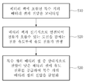
본 발명의 바람직한 실시예에 따른 배터리 팩 내의 셀 전압 밸런싱 방법은: 배터리 팩에 포함된 복수 개의 배터리 셀의 전압을 모니터링 하는 단계(S10); 상기 배터리 팩과 전기적으로 연결되어 전류가 흐를 수 있는 도선을 감싸는 전류 유도부에 유도 전류가 발생하는 단계(S20); 및 상기 복수 개의 배터리 셀 중 상대적으로 전압이 낮은 배터리 셀에 상기 유도 전류를 공급하여 상기 복수 개의 배터리 셀의 전압을 균일하게 하는 단계(S30);를 포함한다.According to a preferred embodiment of the present invention, a cell voltage balancing method in a battery pack includes: monitoring voltages of a plurality of battery cells included in a battery pack (S10); Generating an induced current electrically connected to the battery pack and generating an induced current surrounding a conductive wire through which a current can flow (S20); And supplying the induced current to a battery cell having a relatively low voltage among the plurality of battery cells to uniform the voltages of the plurality of battery cells (S30).
바람직하게, 상기 복수 개의 배터리 셀 각각에는 스위치가 연결되며, 상기 S30단계는, 상대적으로 전압이 낮은 배터리 셀인 저전압 배터리 셀의 전압이 나머지 배터리 셀의 전압에 대응될 때까지 상기 저전압 배터리 셀에 연결된 스위치가 작동하는 것에 의하여 수행된다.Preferably, a switch is connected to each of the plurality of battery cells, and in step S30, a switch connected to the low voltage battery cell until the voltage of the low voltage battery cell, which is a relatively low voltage battery cell, corresponds to the voltage of the remaining battery cells. Is performed by working.
바람직하게, 상기 저전압 배터리 셀이 복수 개인 경우, 상기 S30단계는, 각각의 저전압 배터리 셀의 전압이 나머지 배터리 셀의 전압에 대응될 때까지 각각의 저전압 배터리 셀에 연결된 스위치가 개별적으로 작동하는 것에 의하여 수행된다.Preferably, when there are a plurality of low voltage battery cells, the step S30 may be performed by separately operating switches connected to each low voltage battery cell until the voltage of each low voltage battery cell corresponds to the voltage of the remaining battery cells. Is performed.
바람직하게, 상기 배터리 팩은 상기 도선을 통해 모터부에 연결된다.Preferably, the battery pack is connected to the motor unit through the lead.
바람직하게, 상기 전류 유도부는 솔레노이드 코일이다.Preferably, the current induction part is a solenoid coil.
바람직하게, 상기 솔레노이드 코일은 도전율이 5.8 x 10⁶ mhos/m 이상인 금속 또는 금속 합금 재질이다.Preferably, the solenoid coil is a metal or metal alloy material having a conductivity of 5.8 x 10 6 mhos / m or more.
본 발명의 일 실시예에 따른 배터리 팩 내의 셀 전압 밸런싱 장치는, 배터리 팩과 모터부를 연결하는 도선에 흐르는 전류에 의하여 유도 전류가 발생되는 전류 유도부를 포함함으로써 상대적으로 전압이 낮은 배터리 셀에 상기 유도 전류를 공급할 수 있다. An apparatus for balancing a cell voltage in a battery pack according to an embodiment of the present invention includes a current inducing unit in which an induced current is generated by a current flowing in a conductor connecting a battery pack and a motor unit, thereby inducing the battery voltage in a relatively low voltage battery cell. Can supply current.
이로 인해, 해당 배터리 셀을 충전시킴으로써 복수 개의 배터리 셀 간의 전압 편차를 줄일 수 있으며, 방전(bucking) 방법을 사용하는 전압 밸런싱 장치와 비교시 가격 경쟁력도 확보할 수 있다.As a result, the voltage variation between the plurality of battery cells may be reduced by charging the battery cells, and price competitiveness may be secured when compared to a voltage balancing device using a bucking method.
또한, 짧은 시간 내에 전압 편차를 줄일 수 있으며, 배터리 팩의 파워를 향상시킬 수 있으며, 배터리 팩의 열화 및 수명 단축을 방지할 수 있다.In addition, the voltage deviation can be reduced within a short time, the power of the battery pack can be improved, and the deterioration and the shortening of the life of the battery pack can be prevented.
도 1은 본 발명의 바람직한 실시예에 따른 배터리 팩 내의 셀 전압 밸런싱 장치를 개략적으로 도시한 도면이다.
도 2는 본 발명의 바람직한 실시예에 따른 배터리 팩 내의 셀 전압 밸런싱 방법을 개략적으로 나타내는 흐름도이다.1 is a view schematically showing a cell voltage balancing device in a battery pack according to a preferred embodiment of the present invention.
2 is a flowchart schematically illustrating a cell voltage balancing method in a battery pack according to an exemplary embodiment of the present invention.
실시예의 설명에 있어서, 각 팩, 셀, 또는 부 등이 각 팩, 셀, 또는 부 등의 "상(on)"에 또는 "아래(under)"에 형성되는 것으로 기재되는 경우에 있어, "상(on)"과 "아래(under)"는 "직접(directly)" 또는 "다른 구성요소를 개재하여 (indirectly)" 형성되는 것을 모두 포함한다. 또한 각 구성요소의 상 또는 아래에 대한 기준은 도면을 기준으로 설명한다.In the description of the embodiments, in the case where each pack, cell, or part or the like is described as being formed "on" or "under" of each pack, cell, or part, the "phase" (on) and "under" include both "directly" or "indirectly" formed through other components. In addition, the upper or lower reference of each component is described with reference to the drawings.
도면에서의 각 구성요소들의 크기는 설명을 위하여 과장될 수 있으며, 실제로 적용되는 크기를 의미하는 것은 아니다.
The size of each component in the drawings may be exaggerated for the sake of explanation and does not mean the size actually applied.
이하, 첨부된 도면을 참조하여 본 발명에 따른 실시예를 상세하게 설명한다. 다만, 본 발명이 실시예들에 의해 제한되거나 한정되는 것은 아니다.
Hereinafter, embodiments of the present invention will be described in detail with reference to the accompanying drawings. However, the present invention is not limited or limited by the embodiments.
도 1은 본 발명의 바람직한 실시예에 따른 배터리 팩 내의 셀 전압 밸런싱 장치를 개략적으로 도시한 도면이다.1 is a view schematically showing a cell voltage balancing device in a battery pack according to a preferred embodiment of the present invention.
도 1을 참조하면, 본 발명의 일 측에 따른 배터리 팩 내의 셀 전압 밸런싱 장치는, 복수 개의 배터리 셀(110)을 포함하는 배터리 팩(100), 배터리 팩(100)과 전기적으로 연결되어 전류가 흐를 수 있는 도선(200), 도선(200)을 감싸는 전류 유도부(300), 도선(200)에 흐르는 전류에 의하여 전류 유도부(300)에서 발생되는 유도 전류를 각각의 배터리 셀(110)에 선택적으로 공급할 수 있는 복수 개의 스위치를 갖는 스위치부(400), 복수 개의 스위치 중 상대적으로 전압이 낮은 배터리 셀(110)과 연결된 스위치를 작동시키는 제어부(700)을 포함한다. Referring to FIG. 1, a cell voltage balancing device in a battery pack according to an embodiment of the present invention may include a
또한, 본 발명의 배터리 팩 내의 셀 전압 밸런싱 장치는, 도선(200)을 통해 배터리 팩(100)과 연결되는 모터부(500), 복수 개의 배터리 셀(110)의 전압을 모니터링 하며 상대적으로 전압이 낮은 배터리 셀(110)인 저전압 배터리 셀을 판단하는 모니터링부(600)를 더 포함할 수 있다.In addition, the cell voltage balancing device of the battery pack according to the present invention monitors the voltages of the
배터리 팩(100)은 전기 자동차, 하이브리드 자동차, 및 플러그인 하이브리드 자동차 등의 모터부(500)를 구동시키기 위한 에너지를 공급하는 역할을 한다. 배터리 팩(100)은 복수 개의 배터리 셀들(110)을 포함하며, 이 복수 개의 배터리 셀들(110)은 직렬, 병렬, 또는 직렬과 병렬을 병용한 방식에 의하여 서로 전기적으로 연결된다. 배터리 셀(110)은 충전 및 방전이 가능한 이차 전지일 수 있으며, 바람직하게는 리튬 이차전지일 수 있으나, 이에 제한되지 않는다. The
배터리 팩(100)은, 상술한 전기 자동차, 하이브리드 자동차, 및 플러그인 하이브리드 자동차 등의 운송 수단뿐만 아니라, 파워 툴(Power Tool), 또는 전력 저장용 시스템 등의 중대형 장치 전원으로 다양하게 이용될 수 있다.
The
배터리 팩(100)과 모터부(500)는 도선(200)에 의하여 전기적으로 연결되어 있으므로, 배터리 팩(100)으로부터의 전류는 도선(200)을 통해 모터부(500)로 이동할 수 있다. 모터부(500)는 배터리 팩(100)으로부터 전달된 전기 에너지를 역학적 에너지로 변환 할 수 있다. Since the
모터부(500)로는 AC 모터 또는 DC 모터가 사용될 수 있으며, 모터부(500)는 전기 자동차 등의 운송 수단 또는 전력 저장용 시스템의 구동을 위한 장치로 다양하게 이용될 수 있다.
As the
본 발명의 바람직한 실시예에 따르면, 배터리 팩(100) 및 모터부(500)를 연결하는 도선(200)에는, 도선(200)을 감싸는 전류 유도부(300)가 구비된다. 전류 유도부(300)는 도선(200)에 흐르는 전류를 이용하여 유도 전류를 발생시킬 수 있으며, 이 전류 유도부(300)로는 도선(200)의 외부를 균일하게 감고 있는 솔레노이드 코일(solenoid coil)이 채용될 수 있다. 도 1에 도시된 것과 같이 전류 유도부(300)는 도선(200)의 일부 가닥을 감싸거나, 도선(200)의 모든 가닥을 감쌀 수 있다.According to a preferred embodiment of the present invention, the
이하에서는, 상기 전류 유도부(300)에 유도 전류가 발생하는 원리에 대하여 보다 상세하게 설명하도록 한다.Hereinafter, the principle of generating an induced current in the
통상적으로 제1 전선의 주위를 코일형상의 제2 전선이 둘러싸고 있는 경우, 제1 전선에 전류를 흘리면 코일형상의 제2 전선이 이루고 있는 원통형 공간의 외부에는 거의 자기장이 형성되지 않고, 원통형 공간의 내부에는 비교적 균일한 크기의 자기장이 형성될 수 있다. 동시에 코일형상의 제2 전선에는 유도 전류가 흐르게 된다.In general, when the coil-shaped second wire surrounds the first wire, when a current flows through the first wire, almost no magnetic field is formed outside the cylindrical space formed by the coil-shaped second wire. A magnetic field of relatively uniform size may be formed inside. At the same time, an induced current flows through the coil-shaped second wire.
본 발명의 경우, 도선(200)이 제1 전선에 해당하며, 전류 유도부(300)가 제2 전선에 해당한다. 따라서, 도선(200)에 전류가 흐르면, 전류 유도부(300)에는 유도 전류가 흐르게 된다.In the present invention, the
솔레노이드 코일을 이루고 있는 물질 및 형태에 따라 유도 용량이 결정되며, 유도 용량이 클수록 전류 유도부(300)에 흐르는 유도 전류의 크기가 커진다. 그리고 유도 용량의 값은 하기의 식에서 구한 값과 같다.The inductive capacitance is determined according to the material and shape of the solenoid coil, and the larger the inductive capacitance, the greater the magnitude of the induced current flowing through the
L = μ0n2lA
L = μ 0 n 2 lA
L: 유도 용량L: induction capacity
μ0: 진공에서의 투자율μ 0 : permeability in vacuum
n: 단위길이당 감긴 도선의 수n: number of wound wires per unit length
l: 솔레노이드 코일의 길이l: length of solenoid coil
A: 솔레노이드 코일의 단면적
A: cross-sectional area of solenoid coil
이때, 전류 유도부(300), 즉, 솔레노이드 코일은 전기 전도성이 우수한 금속 또는 금속 합금 재질로 형성될 수 있으며, 바람직하게 도전율이 5.8 x 10⁶ mhos/m 이상(예컨대, 5.8 x 10⁶ ~ 6.17 x 10⁷)인 금속 또는 금속 합금으로 이루어질 수 있으나, 이에 제한되지 않는다. 예컨대, 솔레노이드 코일은 구리 재질로 형성될 수 있고, 반드시 구리 재질이어야만 하는 것은 아니며, 전기 전도성이 우수한 물질이라면 상기의 예에 제한되지 않는다.In this case, the
배터리 팩(100)의 충전 및 방전 과정을 통해 배터리 팩(100)과 모터부(500)를 연결하는 도선(200)에 전류가 발생되고, 도선(200) 주위에 형성된 자기력을 통해 솔레노이드 코일로 이루어진 전류 유도부(300)에서 유도 전류가 발생된다. 발생된 유도 전류는 스위치부(400)를 통해 전압이 낮은 배터리 셀(110)에 공급될 수 있다.Through the charging and discharging process of the
이미 설명한 바와 같이, 스위치부(400)는 복수 개의 스위치를 가지며, 이 복수 개의 스위치는, 전류 유도부(300)에서 발생되는 유도 전류를 각각의 배터리 셀(110)에 선택적으로 공급할 수 있다. 그리고, 상기 스위치로는 반도체 계전기인 SSR(Solid State Relay)이 채용될 수 있다. 스위치로 SSR을 사용함으로써 스위칭 수명을 늘릴 수 있으며, 보다 신뢰성 있는 스위칭을 할 수 있다.
As described above, the
한편, 모니터링부(600)는 복수 개의 배터리 셀(110)의 전압을 모니터링하며, 전압 모니터링은 상시 수행되거나, 주기적으로 수행될 수 있다. 반드시 규칙적으로 모니터링이 수행되어야만 하는 것은 아니며 불규칙적으로 모니터링이 수행될 수도 있다. 또한, 모니터링부(600)는 전압이 낮은 배터리 셀(110)인 저전압 배터리 셀을 판단한다.Meanwhile, the
그리고, 제어부(700)는 상기 모니터링부(600)에 의하여 검출된 저전압 배터리 셀에 연결된 스위치를 작동시키며, 바람직하게는, 저전압 배터리 셀의 전압이 나머지 배터리 셀의 전압에 대응될 때까지 저전압 배터리 셀에 연결된 스위치를 작동시킨다.
The
제어부(700)의 스위치 제어 방식에 대한 이해를 돕기 위하여 이하와 같이 예를 들어 설명하도록 한다.In order to help the understanding of the switch control method of the
충전 또는 방전 중인 대부분의 배터리 셀(110)이 20V를 나타내고 있는 상황에서, 특정 배터리 셀이 15V를 나타낸다고 가정한다.In a situation where
이 경우, 15V를 나타내는 특정 배터리 셀이 저전압 배터리 셀에 해당하며, 모니터링부(600)는 전체 배터리 셀(110) 중 저전압 배터리 셀을 판단하게 된다. 그리고, 제어부(700)는 이 저전압 배터리 셀에 연결된 스위치를 작동시키게 된다. 이 스위치가 작동하게 되면, 전류 유도부(300)로부터의 유도 전류가 저전압 배터리 셀에 인가되며, 저전압 배터리 셀은 유도 전류에 의하여 충전된다.In this case, the specific battery cell representing 15V corresponds to the low voltage battery cell, and the
모니터링부(600)는 전압 모니터링을 계속적으로 수행하고 있으므로, 상기 저전압 배터리 셀의 전압이 나머지 배터리 셀(110)이 나타내는 전압에 대응되는 전압에 도달하였는지 여부를 알 수 있다. 만약, 상기 저전압 배터리 셀의 전압이 나머지 배터리 셀(110)이 나타내는 전압에 대응되는 전압에 도달하게 되면, 제어부는 상기 저전압 배터리 셀에 연결된 스위치의 작동을 정지시키게 되고, 결국, 저전압 배터리 셀을 포함한 모든 배터리 셀(110)의 전압이 서로 대응되게 된다.Since the
여기서, 배터리 셀(110)의 '전압이 서로 대응된다'는 것은 배터리 셀(110) 간의 전압이 서로 동일한 것을 의미할 수 있다. 다만, '전압이 서로 대응된다'는 것이, 전압이 수학적으로 완벽하게 동일한 수치를 나타내는 경우만을 한정하는 것은 아니며, 보다 포괄적인 의미를 나타내는 것이다. 예컨대, 각 배터리 셀(110)의 전압이 20V가 되어야 할 경우, 모든 배터리 셀(110)의 전압이 정확히 20V가 되는 경우뿐만 아니라, 전압들 간에 통상적으로 허용되는 차이가 있는 경우도 '전압이 서로 대응된다'의 의미에 포함된다. 만약, 0.1V의 전압 차이는 배터리 팩(100)의 운용상 허용되는 수치라면, 각 배터리 셀(110)의 전압이 19.9V~20.1V의 범위 내에 있다면 각 배터리 셀(110)의 전압은 서로 대응되는 것이다.
Here, 'voltages corresponding to each other' of the
지금까지는, 제어부(700)가 단 하나의 저전압 배터리 셀을 제어하는 것에 대하여 설명하였으나, 저전압 배터리 셀은 복수 개일 수도 있다. 이 경우, 제어부(700)는 각각의 저전압 배터리 셀의 전압이 나머지 배터리 셀의 전압에 대응될 때까지, 각각의 저전압 배터리 셀에 연결된 스위치를 개별적으로 작동시키게 된다.Up to now, the
예컨대, 각 배터리 셀(110)의 전압이 20V가 되어야 하며, 제1 저전압 배터리 셀은 17V를 나타내고, 제2 저전압 배터리 셀은 15V를 나타내고 있는 상황을 가정해 보기로 한다. For example, it is assumed that the voltage of each
이 경우, 제어부(700)는, 제1 저전압 배터리 셀에 연결된 스위치와 제2 저전압 배터리 셀에 연결된 스위치를 작동시키게 된다. 이 스위치가 작동하게 되면, 전류 유도부(300)로부터의 유도 전류가 제1 저전압 배터리 셀과 제2 저전압 배터리 셀에 인가되며, 제1 저전압 배터리 셀과 제2 저전압 배터리 셀이 모두 유도 전류에 의하여 충전된다.In this case, the
제1 저전압 배터리 셀이 제2 저전압 배터리 셀보다 높은 전압을 나타내고 있었기 때문에, 제1 저전압 배터리 셀이 먼저 20V로 충전될 것이며, 제1 저전압 배터리 셀의 전압이 나머지 배터리 셀(110)의 전압인 20V에 대응되면 제어부(700)는 제1 저전압 배터리 셀에 연결된 스위치를 작동 정지시킨다. 이 때에도 제2 저전압 배터리 셀에 연결된 스위치는 계속 작동하고 있는 상태로 유지된다. Since the first low voltage battery cell exhibited a higher voltage than the second low voltage battery cell, the first low voltage battery cell will first be charged to 20V, and the voltage of the first low voltage battery cell is 20V, which is the voltage of the remaining
이어서, 제2 저전압 배터리 셀의 전압이 나머지 배터리 셀(110)의 전압인 20V에 대응되면 제어부(700)는 제2 저전압 배터리 셀에 연결된 스위치를 작동 정지시킨다. Subsequently, when the voltage of the second low voltage battery cell corresponds to 20 V, which is the voltage of the remaining
이와 같이, 제어부(700)는 각각의 저전압 배터리 셀에 연결된 스위치를 개별적으로 작동시키는 것에 의하여, 모든 배터리 셀(110)의 전압을 서로 대응시킬 수 있다.As such, the
3개 이상의 저전압 배터리 셀이 존재하는 경우의 제어부(700)의 제어 방식은 상술한 예시를 통하여 당업자가 충분히 예상할 수 있음은 물론이다.
Of course, the control method of the
도 2는 본 발명의 바람직한 실시예에 따른 배터리 팩 내의 셀 전압 밸런싱 방법을 개략적으로 나타내는 흐름도이다. 이미 본 발명의 바람직한 실시예에 따른 배터리 팩 내의 셀 전압 밸런싱 장치에 대한 설명에서 밸런싱 방법에 관한 내용이 구체적으로 설명되어 있으나, 이하에서는 도 2를 참조하여, 배터리 팩 내의 셀 전압 밸런싱 방법을 요약적으로 설명하도록 한다.2 is a flowchart schematically illustrating a cell voltage balancing method in a battery pack according to an exemplary embodiment of the present invention. In the description of the cell voltage balancing device in the battery pack according to the preferred embodiment of the present invention, the content of the balancing method has been described in detail. Hereinafter, referring to FIG. To explain.
본 발명의 바람직한 실시예에 따른 배터리 팩 내의 셀 전압 밸런싱 방법은, 배터리 팩(100)에 포함된 복수 개의 배터리 셀(110)의 전압을 모니터링 하는 단계(S10); 배터리 팩(100)과 전기적으로 연결되어 전류가 흐를 수 있는 도선(200)을 감싸는 전류 유도부(300)에 유도 전류가 발생하는 단계(S20); 및 복수 개의 배터리 셀(110) 중 상대적으로 전압이 낮은 배터리 셀에 유도 전류를 공급하여 복수 개의 배터리 셀(110)의 전압을 균일하게 하는 단계(S30);를 포함한다.According to a preferred embodiment of the present invention, a cell voltage balancing method in a battery pack includes: monitoring voltages of a plurality of
상기 S10, S20, S30단계가 시계열적으로 나열된 것은 아니다. S10단계는 배터리 팩(100)이 충방전되는 동안 계속적으로 수행될 수 있고, S20단계도 도선(200)에 전류가 흐르는 동안에 계속적으로 수행될 수 있다. 다만, S30단계는 저전압 배터리 셀이 있는 경우에만 수행된다.Steps S10, S20, and S30 are not listed in time series. The step S10 may be continuously performed while the
복수 개의 배터리 셀(110) 각각에는 스위치가 연결되어 있으며, S30단계는, 상대적으로 전압이 낮은 배터리 셀인 저전압 배터리 셀의 전압이 나머지 배터리 셀(110)의 전압에 대응될 때까지 저전압 배터리 셀에 연결된 스위치가 작동하는 것에 의하여 수행된다.A switch is connected to each of the plurality of
저전압 배터리 셀이 복수 개인 경우라면, 상기 S30단계는, 각각의 저전압 배터리 셀의 전압이 나머지 배터리 셀(110)의 전압에 대응될 때까지 각각의 저전압 배터리 셀에 연결된 스위치가 개별적으로 작동하는 것에 의하여 수행된다.
If there are a plurality of low voltage battery cells, the step S30 may be performed by individually operating a switch connected to each low voltage battery cell until the voltage of each low voltage battery cell corresponds to the voltage of the remaining
더욱 상세하게 설명하면, 모니터링부(600)를 통해 배터리 팩(100) 내의 배터리 셀(110)의 전압이 모니터링 되며, 나머지 배터리 셀(110)에 비해 상대적으로 전압이 낮은 저전압 배터리 셀이 검출된다.In more detail, the voltage of the
모니터링부(600)는 저전압 배터리 셀의 정보를 제어부(700)에 전달한다.The
제어부(700)는 스위치부(400)를 통해 전류 유도부(300)로부터 공급된 유도 전류를 제어할 수 있으며, 저전압 배터리 셀에 연결된 스위치만을 작동하여 저전압 배터리 셀에만 유도 전류가 공급될 수 있도록 한다. 유도 전류를 공급받은 저전압 배터리 셀은 유도 전류에 의하여 충전되어 나머지 배터리 셀(110)들과 대응되는 전압을 갖게 된다.The
이 때, 저전압 배터리 셀은 복수 개 존재할 수 있다. 이 경우, 복수 개의 저전압 배터리 셀에 유도 전류가 모두 공급되며, 이 중에서 특정 저전압 배터리 셀이 더 이상 유도 전류에 의한 충전이 필요하지 않게 되면 그 저전압 배터리 셀에 연결된 스위치의 작동은 정지된다. 따라서, 각각의 저전압 배터리 셀의 유도 전류에 의한 충전완료 시점은 각각 개별적으로 제어될 수 있다.
In this case, a plurality of low voltage battery cells may exist. In this case, all of the induction currents are supplied to the plurality of low voltage battery cells, and when the specific low voltage battery cell no longer needs to be charged by the induction current, the operation of the switch connected to the low voltage battery cell is stopped. Therefore, the charging completion time by the induced current of each low voltage battery cell can be controlled individually.
이와 같이, 본 발명의 바람직한 실시예에 따른 배터리 팩 내의 셀 전압 밸런싱 장치는, 배터리 팩(100)과 모터부(500)를 연결하는 도선(200)에 흐르는 전류로부터 유도 전류를 발생시키는 전류 유도부(300)를 포함함으로써 상대적으로 전압이 낮은 배터리 셀에 유도 전류를 공급할 수 있다.As described above, the cell voltage balancing device in the battery pack according to the preferred embodiment of the present invention includes a current induction unit for generating an induced current from a current flowing in the
이로 인해, 해당 배터리 셀을 충전시킴으로써 다수개의 배터리 셀(110) 간의 전압 편차를 줄일 수 있으며, 방전(bucking) 방법과 비교할 때 가격 경쟁력도 확보할 수 있다. 또한, 짧은 시간 내에 전압 편차를 줄일 수 있으며, 배터리 팩(100)의 파워를 향상시킬 수 있고, 배터리 팩(100)의 열화 및 수명 단축을 방지할 수 있다.As a result, the voltage variation between the plurality of
한편, 종래기술의 방전용 저항(Buck 저항)을 사용하여 배터리 셀(110)의 전압을 밸런싱 하는 방법은 높은 전압을 갖는 배터리 셀(110)의 전압을 낮추는 방법을 사용하므로, 전체 배터리 팩(100)의 에너지량을 줄인다는 단점이 있었다. 그러나, 본 발명의 경우, 전압이 높은 배터리 셀(110)에 대응되는 전압이 되도록 전압이 낮은 배터리 셀의 전압을 높이는 방법을 사용하기 때문에 배터리 팩(100) 전체의 에너지를 증가시킨다는 장점이 있다. On the other hand, the method of balancing the voltage of the
또한, 전압이 낮은 배터리 셀을 충전시키기 위한 에너지원은 전류가 흐르는 도선(200)에 의하여 전류 유도부(300) 발생하는 유도 전류이므로, 배터리 팩(100) 자체로부터 충전을 위한 에너지를 끌어올 필요가 없다는 장점이 있다.
In addition, since the energy source for charging the battery cell having a low voltage is an induced current generated by the current inducing
이상에서 실시예를 중심으로 설명하였으나 이는 단지 예시일 뿐 본 발명을 한정하는 것이 아니며, 본 발명이 속하는 분야의 통상의 지식을 가진 자라면 본 실시예의 본질적인 특성을 벗어나지 않는 범위에서 이상에 예시되지 않은 여러 가지의 변형과 응용이 가능함을 알 수 있을 것이다. 예를 들어, 실시예에 구체적으로 나타난 각 구성요소는 변형하여 실시할 수 있는 것이다. 그리고 이러한 변형과 응용에 관계된 차이점들은 첨부된 청구 범위에서 규정하는 본 발명의 범위에 포함되는 것으로 해석되어야 할 것이다.While the present invention has been particularly shown and described with reference to exemplary embodiments thereof, it is to be understood that the invention is not limited to the disclosed exemplary embodiments, but, on the contrary, It will be understood that various modifications and applications are possible. For example, each component specifically shown in the embodiment can be modified. It is to be understood that all changes and modifications that come within the meaning and range of equivalency of the claims are therefore intended to be embraced therein.
100 : 배터리 팩 110 : 배터리 셀
200 : 도선 300 : 전류 유도부
400 : 스위치부 500 : 모터부
600 : 모니터링부 700 : 제어부100: battery pack 110: battery cell
200: wire 300: current induction part
400: switch unit 500: motor unit
600: monitoring unit 700: control unit
Claims (16)
상기 배터리 팩과 전기적으로 연결되어 전류가 흐를 수 있는 도선;
상기 도선을 감싸는 전류 유도부;
상기 도선에 흐르는 전류에 의하여 상기 전류 유도부에서 발생되는 유도 전류를 각각의 배터리 셀에 선택적으로 공급할 수 있는 복수 개의 스위치를 갖는 스위치부; 및
상기 복수 개의 스위치 중 상대적으로 전압이 낮은 배터리 셀과 연결된 스위치를 작동시키는 제어부;를 포함하는 배터리 팩 내의 셀 전압 밸런싱 장치.A battery pack including a plurality of battery cells;
A conductive wire electrically connected to the battery pack to allow current to flow;
A current induction part surrounding the conductor;
A switch unit having a plurality of switches capable of selectively supplying each of the battery cells with an induced current generated by the current inducing unit by a current flowing in the conductive wire; And
And a control unit configured to operate a switch connected to a battery cell having a relatively low voltage among the plurality of switches.
상기 복수 개의 배터리 셀의 전압을 모니터링 하며, 상대적으로 전압이 낮은 배터리 셀인 저전압 배터리 셀을 판단하는 모니터링부를 더 포함하는 배터리 팩 내의 셀 전압 밸런싱 장치.The method of claim 1,
And a monitoring unit configured to monitor voltages of the plurality of battery cells and determine a low voltage battery cell that is a battery cell having a relatively low voltage.
상기 제어부는 상기 모니터링부에 의하여 검출된 저전압 배터리 셀에 연결된 스위치를 작동시키는 것을 특징으로 하는 배터리 팩 내의 셀 전압 밸런싱 장치.The method of claim 2,
And the control unit operates a switch connected to the low voltage battery cell detected by the monitoring unit.
상기 제어부는, 상대적으로 전압이 낮은 배터리 셀인 저전압 배터리 셀의 전압이 나머지 배터리 셀의 전압에 대응될 때까지 상기 저전압 배터리 셀에 연결된 스위치를 작동시키는 것을 특징으로 하는 배터리 팩 내의 셀 전압 밸런싱 장치.The method of claim 1,
And the control unit operates the switch connected to the low voltage battery cell until the voltage of the low voltage battery cell, which is a relatively low voltage battery cell, corresponds to the voltage of the remaining battery cells.
상대적으로 전압이 낮은 배터리 셀인 저전압 배터리 셀이 복수 개인 경우, 상기 제어부는 각각의 저전압 배터리 셀의 전압이 나머지 배터리 셀의 전압에 대응될 때까지, 각각의 저전압 배터리 셀에 연결된 스위치를 개별적으로 작동시키는 것을 특징으로 하는 배터리 팩 내의 셀 전압 밸런싱 장치.The method of claim 1,
When there are a plurality of low voltage battery cells, which are relatively low voltage battery cells, the control unit individually operates the switches connected to each low voltage battery cell until the voltage of each low voltage battery cell corresponds to the voltage of the remaining battery cells. A cell voltage balancing device in a battery pack, characterized in that.
상기 배터리 셀은 리튬 이차전지인 것을 특징으로 하는 배터리 팩 내의 셀 전압 밸런싱 장치.The method of claim 1,
The battery cell balancing device in a battery pack, characterized in that the lithium secondary battery.
상기 도선을 통해 상기 배터리 팩과 연결되는 모터부를 더 포함하는 배터리 팩 내의 셀 전압 밸런싱 장치.The method of claim 1,
And a motor unit connected to the battery pack through the lead.
상기 전류 유도부는 솔레노이드 코일인 것을 특징으로 하는 배터리 팩 내의 셀 전압 밸런싱 장치.The method of claim 1,
The current inducing unit is a cell voltage balancing device in a battery pack, characterized in that the solenoid coil.
상기 솔레노이드 코일은 도전율이 5.8 x 10⁶ mhos/m 이상인 금속 또는 금속 합금 재질인 것을 특징으로 하는 배터리 팩 내의 셀 전압 밸런싱 장치.9. The method of claim 8,
The solenoid coil is a cell voltage balancing device in a battery pack, characterized in that the conductivity of the metal or metal alloy material of 5.8 x 10 6 mhos / m or more.
상기 스위치는 SSR(Solid State Relay)인 것을 특징으로 하는 배터리 팩 내의 셀 전압 밸런싱 장치.The method of claim 1,
The switch is a cell voltage balancing device in a battery pack, characterized in that the solid state relay (SSR).
상기 배터리 팩과 전기적으로 연결되어 전류가 흐를 수 있는 도선을 감싸는 전류 유도부에 유도 전류가 발생하는 단계(S20); 및
상기 복수 개의 배터리 셀 중 상대적으로 전압이 낮은 배터리 셀에 상기 유도 전류를 공급하여 상기 복수 개의 배터리 셀의 전압을 균일하게 하는 단계(S30);를 포함하는 배터리 팩 내의 셀 전압 밸런싱 방법.Monitoring voltages of the plurality of battery cells included in the battery pack (S10);
Generating an induced current electrically connected to the battery pack and generating an induced current surrounding a conductive wire through which a current can flow (S20); And
And supplying the induced current to a battery cell having a relatively low voltage among the plurality of battery cells to equalize the voltages of the plurality of battery cells (S30).
상기 복수 개의 배터리 셀 각각에는 스위치가 연결되며,
상기 S30단계는, 상대적으로 전압이 낮은 배터리 셀인 저전압 배터리 셀의 전압이 나머지 배터리 셀의 전압에 대응될 때까지 상기 저전압 배터리 셀에 연결된 스위치가 작동하는 것에 의하여 수행되는 것을 특징으로 하는 배터리 팩 내의 셀 전압 밸런싱 방법.12. The method of claim 11,
A switch is connected to each of the plurality of battery cells,
The step S30 is performed by operating a switch connected to the low voltage battery cell until the voltage of the low voltage battery cell, which is a relatively low voltage battery cell, corresponds to the voltage of the remaining battery cells. Voltage balancing method.
상기 저전압 배터리 셀이 복수 개인 경우, 상기 S30단계는, 각각의 저전압 배터리 셀의 전압이 나머지 배터리 셀의 전압에 대응될 때까지 각각의 저전압 배터리 셀에 연결된 스위치가 개별적으로 작동하는 것에 의하여 수행되는 것을 특징으로 하는 배터리 팩 내의 셀 전압 밸런싱 방법.The method of claim 12,
When there are a plurality of low voltage battery cells, the step S30 may be performed by individually operating switches connected to each low voltage battery cell until the voltage of each low voltage battery cell corresponds to the voltage of the remaining battery cells. A cell voltage balancing method within a battery pack.
상기 배터리 팩은 상기 도선을 통해 모터부에 연결된 것을 특징으로 하는 배터리 팩 내의 셀 전압 밸런싱 방법.12. The method of claim 11,
And the battery pack is connected to a motor unit through the conductive line.
상기 전류 유도부는 솔레노이드 코일인 것을 특징으로 하는 배터리 팩 내의 셀 전압 밸런싱 방법.12. The method of claim 11,
And the current inducing unit is a solenoid coil.
상기 솔레노이드 코일은 도전율이 5.8 x 10⁶ mhos/m 이상인 금속 또는 금속 합금 재질인 것을 특징으로 하는 배터리 팩 내의 셀 전압 밸런싱 방법.16. The method of claim 15,
The solenoid coil is a cell voltage balancing method in a battery pack, characterized in that the conductivity of the metal or metal alloy material of 5.8 x 10 6 mhos / m or more.
Applications Claiming Priority (2)
| Application Number | Priority Date | Filing Date | Title |
|---|---|---|---|
| KR20120012708 | 2012-02-08 | ||
| KR1020120012708 | 2012-02-08 |
Publications (2)
| Publication Number | Publication Date |
|---|---|
| KR20130091692A true KR20130091692A (en) | 2013-08-19 |
| KR101476027B1 KR101476027B1 (en) | 2014-12-23 |
Family
ID=49216757
Family Applications (1)
| Application Number | Title | Priority Date | Filing Date |
|---|---|---|---|
| KR1020130014323A KR101476027B1 (en) | 2012-02-08 | 2013-02-08 | Apparatus and method for balancing cell voltage in battery pack |
Country Status (1)
| Country | Link |
|---|---|
| KR (1) | KR101476027B1 (en) |
Cited By (3)
| Publication number | Priority date | Publication date | Assignee | Title |
|---|---|---|---|---|
| KR20150046599A (en) * | 2013-10-22 | 2015-04-30 | 주식회사 엘지화학 | Apparatus for managing battery pack and including the same |
| KR20170058073A (en) * | 2015-11-18 | 2017-05-26 | 주식회사 엘지화학 | Apparatus of Measuring Voltage of Battery Pack and Method thereof |
| WO2021215824A1 (en) * | 2020-04-22 | 2021-10-28 | 주식회사 엘지에너지솔루션 | Low voltage cell detection method, and battery management system for providing method |
Family Cites Families (4)
| Publication number | Priority date | Publication date | Assignee | Title |
|---|---|---|---|---|
| JP3764633B2 (en) * | 2000-06-26 | 2006-04-12 | Necトーキン株式会社 | Electric energy storage device, cell energy amount adjusting device, and cell energy amount adjusting method |
| JP4305419B2 (en) * | 2005-06-21 | 2009-07-29 | 株式会社デンソー | Battery equalization circuit |
| JP5046570B2 (en) * | 2006-06-22 | 2012-10-10 | Fdk株式会社 | Series cell voltage balance circuit |
| KR101093597B1 (en) * | 2009-01-30 | 2011-12-15 | 한국과학기술원 | Charge Equalization Apparatus for Series-Connected Battery String Using Regulated Voltage Source |
-
2013
- 2013-02-08 KR KR1020130014323A patent/KR101476027B1/en active IP Right Grant
Cited By (3)
| Publication number | Priority date | Publication date | Assignee | Title |
|---|---|---|---|---|
| KR20150046599A (en) * | 2013-10-22 | 2015-04-30 | 주식회사 엘지화학 | Apparatus for managing battery pack and including the same |
| KR20170058073A (en) * | 2015-11-18 | 2017-05-26 | 주식회사 엘지화학 | Apparatus of Measuring Voltage of Battery Pack and Method thereof |
| WO2021215824A1 (en) * | 2020-04-22 | 2021-10-28 | 주식회사 엘지에너지솔루션 | Low voltage cell detection method, and battery management system for providing method |
Also Published As
| Publication number | Publication date |
|---|---|
| KR101476027B1 (en) | 2014-12-23 |
Similar Documents
| Publication | Publication Date | Title |
|---|---|---|
| Omariba et al. | Review of battery cell balancing methodologies for optimizing battery pack performance in electric vehicles | |
| JP5812025B2 (en) | Power storage system for stationary use and control method | |
| CN103779620B (en) | Accumulating system | |
| CN103580094B (en) | Accumulating system and the control method for accumulating system | |
| US9933491B2 (en) | Electric storage system | |
| JP5851551B2 (en) | Secondary battery charge / discharge control apparatus and method including active balance circuit and algorithm for charging / discharging a plurality of secondary batteries connected in series | |
| JP3934365B2 (en) | Battery charge / discharge control method | |
| US20100104929A1 (en) | Battery management system for an electrical device working in accordance with galvanic principles, for example a lithium-ion cell | |
| CN103580214B (en) | Charging device and method of operation thereof | |
| KR102331070B1 (en) | battery pack and charging control method for battery pack | |
| JP6797689B2 (en) | Precharge and voltage supply system for DC-AC inverter | |
| CN105375539B (en) | Automatic balance charger for power battery | |
| KR20070050043A (en) | Method and apparatus for balancing multi-cell lithium battery systems | |
| TWI804503B (en) | Power storage system and electric equipment | |
| JP2015073429A (en) | Method for detecting cell state-of-charge and state-of-discharge divergence of series string of batteries or capacitors | |
| KR101496516B1 (en) | Battery thermal management system and method for driving the same | |
| CN105247756A (en) | Method and apparatus for charging rechargeable cells | |
| CN101960690A (en) | Recharging device and recharging method | |
| JP2009286292A (en) | Vehicular power supply device | |
| JP6361545B2 (en) | Current control device | |
| CN103094944A (en) | Multi-section type battery module charging method and device | |
| CN108808751A (en) | A kind of electrical changing station power supply system and electrical changing station method of supplying power to | |
| CN103311065A (en) | Arc chuteless dc current interruptor | |
| KR20120077482A (en) | Balance charging apparatus for battery module | |
| US10391880B2 (en) | Battery pack and electric vehicle including the same |
Legal Events
| Date | Code | Title | Description |
|---|---|---|---|
| A201 | Request for examination | ||
| E902 | Notification of reason for refusal | ||
| E701 | Decision to grant or registration of patent right | ||
| GRNT | Written decision to grant | ||
| FPAY | Annual fee payment |
Payment date: 20170919 Year of fee payment: 4 |
|
| FPAY | Annual fee payment |
Payment date: 20181016 Year of fee payment: 5 |