KR20130089637A - Improvements in or relating to ophthalmology - Google Patents
Improvements in or relating to ophthalmology Download PDFInfo
- Publication number
- KR20130089637A KR20130089637A KR1020137001275A KR20137001275A KR20130089637A KR 20130089637 A KR20130089637 A KR 20130089637A KR 1020137001275 A KR1020137001275 A KR 1020137001275A KR 20137001275 A KR20137001275 A KR 20137001275A KR 20130089637 A KR20130089637 A KR 20130089637A
- Authority
- KR
- South Korea
- Prior art keywords
- light
- retina
- eye
- point
- arc
- Prior art date
Links
Images

Classifications
-
- A—HUMAN NECESSITIES
- A61—MEDICAL OR VETERINARY SCIENCE; HYGIENE
- A61B—DIAGNOSIS; SURGERY; IDENTIFICATION
- A61B3/00—Apparatus for testing the eyes; Instruments for examining the eyes
- A61B3/10—Objective types, i.e. instruments for examining the eyes independent of the patients' perceptions or reactions
- A61B3/12—Objective types, i.e. instruments for examining the eyes independent of the patients' perceptions or reactions for looking at the eye fundus, e.g. ophthalmoscopes
-
- A—HUMAN NECESSITIES
- A61—MEDICAL OR VETERINARY SCIENCE; HYGIENE
- A61B—DIAGNOSIS; SURGERY; IDENTIFICATION
- A61B3/00—Apparatus for testing the eyes; Instruments for examining the eyes
- A61B3/0008—Apparatus for testing the eyes; Instruments for examining the eyes provided with illuminating means
-
- A—HUMAN NECESSITIES
- A61—MEDICAL OR VETERINARY SCIENCE; HYGIENE
- A61B—DIAGNOSIS; SURGERY; IDENTIFICATION
- A61B3/00—Apparatus for testing the eyes; Instruments for examining the eyes
- A61B3/10—Objective types, i.e. instruments for examining the eyes independent of the patients' perceptions or reactions
- A61B3/14—Arrangements specially adapted for eye photography
-
- A—HUMAN NECESSITIES
- A61—MEDICAL OR VETERINARY SCIENCE; HYGIENE
- A61F—FILTERS IMPLANTABLE INTO BLOOD VESSELS; PROSTHESES; DEVICES PROVIDING PATENCY TO, OR PREVENTING COLLAPSING OF, TUBULAR STRUCTURES OF THE BODY, e.g. STENTS; ORTHOPAEDIC, NURSING OR CONTRACEPTIVE DEVICES; FOMENTATION; TREATMENT OR PROTECTION OF EYES OR EARS; BANDAGES, DRESSINGS OR ABSORBENT PADS; FIRST-AID KITS
- A61F9/00—Methods or devices for treatment of the eyes; Devices for putting-in contact lenses; Devices to correct squinting; Apparatus to guide the blind; Protective devices for the eyes, carried on the body or in the hand
- A61F9/007—Methods or devices for eye surgery
-
- G—PHYSICS
- G02—OPTICS
- G02B—OPTICAL ELEMENTS, SYSTEMS OR APPARATUS
- G02B26/00—Optical devices or arrangements for the control of light using movable or deformable optical elements
- G02B26/08—Optical devices or arrangements for the control of light using movable or deformable optical elements for controlling the direction of light
- G02B26/10—Scanning systems
-
- G—PHYSICS
- G02—OPTICS
- G02B—OPTICAL ELEMENTS, SYSTEMS OR APPARATUS
- G02B6/00—Light guides; Structural details of arrangements comprising light guides and other optical elements, e.g. couplings
- G02B6/0001—Light guides; Structural details of arrangements comprising light guides and other optical elements, e.g. couplings specially adapted for lighting devices or systems
- G02B6/0005—Light guides; Structural details of arrangements comprising light guides and other optical elements, e.g. couplings specially adapted for lighting devices or systems the light guides being of the fibre type
- G02B6/0006—Coupling light into the fibre
Landscapes
- Health & Medical Sciences (AREA)
- Life Sciences & Earth Sciences (AREA)
- Ophthalmology & Optometry (AREA)
- Physics & Mathematics (AREA)
- Surgery (AREA)
- General Health & Medical Sciences (AREA)
- Biomedical Technology (AREA)
- Heart & Thoracic Surgery (AREA)
- Veterinary Medicine (AREA)
- Engineering & Computer Science (AREA)
- Public Health (AREA)
- Animal Behavior & Ethology (AREA)
- Molecular Biology (AREA)
- Biophysics (AREA)
- Medical Informatics (AREA)
- General Physics & Mathematics (AREA)
- Optics & Photonics (AREA)
- Nuclear Medicine, Radiotherapy & Molecular Imaging (AREA)
- Vascular Medicine (AREA)
- Eye Examination Apparatus (AREA)
- Laser Surgery Devices (AREA)
Abstract
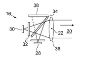
본 발명은 눈의 망막을 조사(illuminating), 영상화 및 치료하는 장치 및 방법을 제공한다. 이 장치(10)는, 하나 이상의 광원(16)을 포함하며, 상기 하나 이상의 광원(16)은, 복수 개의 점원(22)들로부터 시준 광(20)을 제공하도록 구성되며, 각각의 점원(22)은 아크(18) 상에 놓이며, 상기 하나 이상의 광원(16)은, 아크(18)의 중심점(26)을 향해 아크(18)의 반경(24)을 따라 각각의 점원(22)으로부터 시준 광(20)을 지향시키도록 구성되며, 사용시, 상기 장치(10)는, 아크(18)의 중심점(26)이 눈(14)의 동공점(40)과 실질적으로 일치하도록 배열됨으로써, 망막(12)을 조사하기 위해서 점원(22)으로부터 눈(14)의 동공점(40)을 통해 시준 광(20)이 투과(transmitted)된다.
The present invention provides apparatus and methods for illuminating, imaging and treating the retina of the eye. The device 10 comprises one or more light sources 16, the one or more light sources 16 configured to provide collimating light 20 from a plurality of point sources 22, each point source 22 being one. ) Lies on the arc 18, wherein the one or more light sources 16 collimate from each point source 22 along the radius 24 of the arc 18 toward the center point 26 of the arc 18. And, in use, the device 10 is arranged such that the center point 26 of the arc 18 substantially coincides with the pupil point 40 of the eye 14. A collimated light 20 is transmitted from the point source 22 through the pupil point 40 of the eye 14 to irradiate 12).
Description
본 발명은 사람의 눈의 망막을 조사, 영상화 및 치료하기 위한 장치 및 방법에 관한 것이다.
The present invention relates to apparatus and methods for irradiating, imaging and treating the retina of a human eye.
스캐닝 레이저 검안경(scanning laser ophthalmoscope, SLO)들과 같은 영상화 시스템들은 레이저 스캐닝 요소들, 스캔 전달 미러들, 레이저 소스들 및 검지기들과 같은 다수의 광학적 구성요소들을 포함할 수 있다. 레이저 스캐닝 배열체는, 통상 고속으로 회전하는 다각형(polygonal) 미러 및 모터 구동식 저속 미러를 포함하는 2 개의 분리된 직교하는 스캐닝 요소들로 구성된다. 이러한 요소들은 사람의 망막의 래스터(raster) 스캔 패턴을 생성하기 위해 사용된다. 다면경(polygon mirror)은 복수 개의 마면(facet)들을 가지며, 전형적으로, 레이저 빔의 수직 스캐닝을 제공하고, 저속 미러는 전형적으로 레이저 빔의 수평 스캐닝을 제공한다. 스캔 전달 미러는, 스캔닝 요소들에 의해 생성된 2 차원 레이저 스캔 패턴을 눈의 망막에 전달한다.
Imaging systems such as scanning laser ophthalmoscopes (SLOs) may include a number of optical components such as laser scanning elements, scan delivery mirrors, laser sources and detectors. The laser scanning arrangement consists of two separate orthogonal scanning elements, typically comprising a polygonal mirror rotating at high speed and a motor driven low speed mirror. These elements are used to generate a raster scan pattern of the human retina. Polygon mirrors have a plurality of facets, typically providing vertical scanning of the laser beam, and low speed mirrors typically providing horizontal scanning of the laser beam. The scan transfer mirror delivers the two-dimensional laser scan pattern generated by the scanning elements to the eye's retina.
이러한 영상화 시스템들이 눈의 망막에 허용가능한 영상들을 제공하지만, 이들 시스템들은 대형으로 제조하기에는 고가이며(레이저 스캐닝 요소들 및 스캔 전달 미러가 특히 고가의 구성요소들임), 다수의 광학적 구성요소들로 인해, 낮은 광학적 효율을 갖는다는 점에서 제한된다.
While these imaging systems provide acceptable images for the retina of the eye, these systems are expensive to manufacture in large scales (laser scanning elements and scan delivery mirrors are particularly expensive components) and due to the large number of optical components However, it is limited in that it has low optical efficiency.
본 발명의 제 1 양태에 따르면, 눈의 망막을 조사(illuminating)하는 장치가 제공되며, 상기 장치는, According to a first aspect of the present invention there is provided an apparatus for illuminating the retina of the eye, the apparatus comprising:
하나 이상의 광원(light source)을 포함하며,One or more light sources,
상기 하나 이상의 광원은, 복수 개의 점원(point source)들로부터 시준 광을 제공하도록 구성되며,The one or more light sources are configured to provide collimating light from a plurality of point sources,
각각의 점원은 아크 상에 놓이며,Each clerk is placed on the arc,
상기 하나 이상의 광원은, 아크의 중심점을 향해 아크의 반경을 따라 각각의 점원으로부터 시준 광을 지향시키도록 구성되며, The at least one light source is configured to direct collimating light from each point source along the arc radius towards the center point of the arc,
사용시, 상기 장치는, 아크의 중심점이 눈의 동공점과 실질적으로 일치하도록 배열됨으로써, 망막을 조사하기 위해서 점원으로부터 눈의 동공점을 통해 시준 광이 투과(transmitted)된다.
In use, the device is arranged such that the center point of the arc is substantially coincident with the pupil point of the eye, whereby collimating light is transmitted from the point source through the eye pupil point to irradiate the retina.
상기 장치는 복수 개의 광원들을 포함하고, 각각의 광원은 각각의 점원으로부터 시준 광을 제공하도록 구성된다.
The apparatus includes a plurality of light sources, each light source configured to provide collimating light from each point source.
아크의 중심은 눈의 제 1 노달 포인트(first nodal point)와 일치할 수 있다.The center of the arc may coincide with the first nodal point of the eye.
복수 개의 시준 광 점원들이, 각각의 점원이 인접한 점원으로부터 등거리에 있도록 어레이에 배열될 수 있다. 대안으로, 시준 광 점원들이 아크를 따라 서로 이웃하도록 시준 광 점원들이 배열될 수 있다.
A plurality of collimating light point sources can be arranged in the array such that each point source is equidistant from adjacent point sources. Alternatively, the collimating light points can be arranged such that the collimating light points are adjacent to each other along the arc.
아크의 반경은 3mm 내지 500mm 일 수 있다. 바람직하게는, 아크의 반경은 5mm 내지 200mm 일 수 있다. 더 바람직하게는, 아크의 반경은 25mm 이다.
The radius of the arc can be 3mm to 500mm. Preferably, the radius of the arc can be 5mm to 200mm. More preferably, the radius of the arc is 25 mm.
장치는, 1 개 내지 16,000,000 개의 광원들을 포함할 수 있다. 바람직하게는, 장치는 100 개 내지 16,000,000 개의 광원들을 포함한다. 더 바람직하게는, 장치는 4,000 개의 광원들을 포함한다.
The device may comprise 1 to 16,000,000 light sources. Preferably, the device comprises 100 to 16,000,000 light sources. More preferably, the device comprises 4,000 light sources.
광원들은, 레이저, 발광 다이오드(LED), 수직공동표면 발광 레이저(Vertical Cavity Surface Emitting Laser, VCSEL), 초형광 다이오드(super luminescent diode), 다이오드 레이저 또는 시준 백열등(collimated incandescent lamp)을 포함할 수 있다.
The light sources may include a laser, a light emitting diode (LED), a vertical cavity surface emitting laser (VCSEL), a super luminescent diode, a diode laser or a collimated incandescent lamp. .
각각의 광원은 450nm 내지 1000nm 의 파장을 광에 제공하도록 구성될 수 있다. 바람직하게는, 각각의 광원은 488nm 내지 700nm 의 파장을 광에 제공하도록 구성될 수 있다. 더 바람직하게는, 각각의 광원은 515nm 내지 650nm 의 파장을 광에 제공한다.
Each light source can be configured to provide light with a wavelength of 450 nm to 1000 nm. Preferably, each light source can be configured to provide light with a wavelength between 488 nm and 700 nm. More preferably, each light source provides light with a wavelength of 515 nm to 650 nm.
각각의 광원은 500nW 내지 1W 의 전력을 광에 제공하도록 구성될 수 있다.
Each light source can be configured to provide light from 500 nW to 1 W of power.
상기 각각의 광원은 하나 또는 그 초과의 상이한 파장들의 광원들을 포함할 수 있다.
Each light source may comprise light sources of one or more different wavelengths.
상기 각각의 광원은, 제공된 광의 파장이 가변적이도록 구성될 수 있다.
Each light source can be configured such that the wavelength of the provided light is variable.
상기 각각의 광원은, 제공된 광의 전력이 가변적이도록 구성될 수 있다,
Each of the light sources may be configured such that the power of the provided light is variable,
상기 각각의 광원은 점원에 또는 점원에 인접하게 위치될 수 있다.
Each light source may be located at or adjacent to the point source.
상기 각각의 광원은 상기 점원으로부터 시준 광을 제공하기 위해서 시준 렌즈를 포함할 수 있다.
Each light source may comprise a collimating lens to provide collimating light from the point source.
상기 각각의 광원은 상기 점원으로부터 멀리 위치될 수 있다. 이러한 배열체에서, 광은 각각의 광원으로부터 광 가이드(guide), 광 섬유 등과 같은 광 전송 디바이스를 경유하여 점원으로 전송된다. 이러한 배열체에서, 각각의 광원은, 광 전송 디바이스에의 입력으로 시준 광을 제공하기 위해서 광 전송 디바이스에 입력으로 제공되는 제 1 시준 렌즈 및 점원에 시준 광을 제공하기 위해서 광 전송 디바이스의 출력에 제공되는 제 2 시준 렌즈를 포함할 수 있다.
Each light source may be located far from the point source. In this arrangement, light is transmitted from each light source to a point source via a light transmission device such as a light guide, an optical fiber or the like. In such an arrangement, each light source is coupled to an output of the light transmission device to provide collimation light to a first collimating lens and a point source provided as input to the light transmission device for providing collimation light as input to the light transmission device. It may include a second collimation lens provided.
각각의 광원은 광원의 전력을 감시하기 위해서 전력 모니터를 포함할 수 있다.
Each light source may include a power monitor to monitor the power of the light source.
각각의 광원은 선형 편광기(linear polariser) 또는 파장판(waveplate)과 같은 극성화 요소를 포함할 수 있다.
Each light source may comprise a polarizing element, such as a linear polarizer or waveplate.
장치는, 각각의 광원이 독립적으로 작동될 수 있도록 구성될 수 있다. 장치는, 각각의 광원이 순차적으로 작동되도록 구성될 수 있다.
The device may be configured such that each light source can be operated independently. The device may be configured such that each light source is operated sequentially.
장치는, 각각의 광원의 작동이 자동화되도록 구성될 수 있다. 각각의 광원의 작동은 컴퓨터로 제어될 수 있다.
The device may be configured such that the operation of each light source is automated. The operation of each light source can be computer controlled.
장치는, 복수 개의 점원들 및 아크의 중심점에 의해 형성되는 평면에 실질적으로 놓이는 축을 중심으로 회전가능할 수 있다. 이러한 배열체에서, 장치는 망막 상에서 선에 대향하는 망막의 표면을 조사하기 위해 사용될 수 있다. 즉, 회전 없이, 장치가 망막 상의 선을 조사하고, 그리고 회전에 의해, 장치가 망막의 표면을 조사한다.
The device may be rotatable about an axis substantially lying in the plane defined by the plurality of point sources and the center point of the arc. In such an arrangement, the device can be used to irradiate the surface of the retina opposite the line on the retina. That is, without rotation, the device irradiates a line on the retina and, by rotation, the device irradiates the surface of the retina.
장치의 회전축은 눈의 동공점 둘레에 위치될 수 있다. 장치의 회전축은 눈의 동공점과 일치할 수 있다.
The axis of rotation of the device may be located around the pupil point of the eye. The axis of rotation of the device may coincide with the pupil point of the eye.
장치는, 축을 중심으로 한 장치의 회전이 자동화되도록 구성될 수 있다. 장치의 회전은 컴퓨터로 제어될 수 있다.
The device may be configured such that rotation of the device about the axis is automated. The rotation of the device can be computer controlled.
장치는, 복수 개의 동심으로 정렬되는 아크들 상에 놓이는 복수 개의 시준 점원들을 포함할 수 있다. 각각의 아크는 동일한 반경 및 중심점을 가질 수 있다. 이러한 배열체에서, 각각의 점원으로부터의 시준 광은 중심점을 향해 각각의 아크의 반경을 따라 반경 방향 내측방으로 지향된다. 사용시, 장치는, 중심점이 눈의 동공점과 실질적으로 일치하도록 배열됨으로써, 망막을 조사하기 위해서 각각의 점원으로부터 눈의 동공점을 통해 시준 광이 투과된다. 이러한 배열의 효과는, 이 장치가 각각의 점원으로부터 중심점을 통해 그리고 눈의 망막으로 시준 광을 지향시키기 위한 2 차원 반구형 조사 표면을 제공한다는 점이다.
The apparatus may include a plurality of collimating clerks lying on a plurality of concentrically aligned arcs. Each arc can have the same radius and center point. In this arrangement, collimation light from each point source is directed radially inward along the radius of each arc towards the center point. In use, the device is arranged such that the center point is substantially coincident with the pupil point of the eye, whereby collimating light is transmitted from each point source through the eye pupil point to irradiate the retina. The effect of this arrangement is that the device provides a two-dimensional hemispherical irradiation surface for directing collimating light from each point source through the center point and into the eye retina.
장치가 제 1 눈의 제 1 망막을 조사하기 위해 사용될 수 있는 제 1 위치와, 장치가 제 2 눈의 제 2 망막을 조사하기 위해 사용될 수 있는 제 2 위치 사이에서, 장치가 선회가능할 수 있다.
The device may be pivotable between a first position where the device may be used to irradiate the first retina of the first eye and a second position where the device may be used to irradiate the second retina of the second eye.
장치는, 망막의 영상을 만들기 위해서 망막으로부터 반사된 광을 검지하는 광 검지기를 더 포함할 수 있다. 이러한 배열체에서, 장치는 망막을 조사하여 망막의 조사된 부분의 영상을 획득한다. 이러한 영상은 1 차원 영상이다. 장치가 상기 기재된 축을 중심으로 회전될 때, 망막의 2 차원 영상을 획득하기 위해서 망막의 복수 개의 1 차원 영상들이 획득되어 조합될 수 있다.
The apparatus may further include a light detector for detecting light reflected from the retina to make an image of the retina. In this arrangement, the device illuminates the retina to obtain an image of the irradiated portion of the retina. This image is a one-dimensional image. When the device is rotated about the axis described above, a plurality of one-dimensional images of the retina may be obtained and combined to obtain a two-dimensional image of the retina.
각각의 광원은 망막의 영상을 만들기 위해서 망막으로부터 반사된 광을 검지하는 광 검지기를 포함할 수 있다.
Each light source may include a light detector that detects light reflected from the retina to make an image of the retina.
광 검지기(들)는, 애벌런치 포토다이오드(APD)들, PIN 다이오드들, 광전자증배관(PMT)들, 실리콘 광증배관(SPM)들 또는 유사한 단일점 검지기들과 같은 패스트 포토 검지기들을 포함할 수 있다.
The photo detector (s) may include fast photo detectors such as avalanche photodiodes (APDs), PIN diodes, photomultipliers (PMTs), silicon photomultipliers (SPMs) or similar single point detectors. have.
광 검지기들은 광원들에 위치될 수 있다.
Light detectors may be located in the light sources.
장치는, 각각의 광 검지기의 작동이 자동화되도록 구성될 수 있다. 각각의 광 검지기의 작동은 컴퓨터로 제어될 수 있다. 각각의 광 검지기의 작동은 각각의 광원과 동기화된다(synchronised).
The device may be configured such that the operation of each light detector is automated. The operation of each light detector can be computer controlled. The operation of each light detector is synchronized with each light source.
각각의 검지기는 망막으로부터 검지기로 반사된 시준 광을 집중시키는 렌즈를 포함할 수 있다. 검지기는 바람직하게는, 점 검지기이며, 렌즈는 점 검지기 상의 점으로 반사된 시준 광을 집중시킨다.
Each probe may include a lens that focuses collimated light reflected from the retina to the probe. The detector is preferably a point detector and the lens focuses the collimated light reflected to the point on the point detector.
장치는, 각각의 광원의 시준 렌즈 및 각각의 검지기의 집중 렌즈로써 기능하는 단일 렌즈를 포함할 수 있다.
The device may comprise a single lens that functions as a collimating lens of each light source and a focusing lens of each detector.
장치는, 각각의 광원과 각각의 검지기 사이에 위치되는 빔 분할기를 포함할 수 있다. 이러한 배열체에서, 빔 분할기는 광원으로부터 광의 일부를 시준 렌즈로 반사시킨다. 광원으로부터의 광의 나머지 부분은 빔 분할기를 통해 그리고 전력 모니터를 향해 투과된다. 망막으로부터 반사된 시준 광의 대부분은 빔 분할기를 통해 검지기로 투과된다.
The apparatus may include a beam splitter positioned between each light source and each detector. In this arrangement, the beam splitter reflects some of the light from the light source to the collimating lens. The remainder of the light from the light source is transmitted through the beam splitter and towards the power monitor. Most of the collimated light reflected from the retina is transmitted to the detector through the beam splitter.
장치는 망막의 획득된 영상들을 디스플레이, 저장 및/또는 조합을 위한 하나 또는 그 초과의 데이터 처리 디바이스들을 더 포함할 수 있다.
The apparatus may further comprise one or more data processing devices for displaying, storing and / or combining the obtained images of the retina.
본 발명의 제 2 양태에 따르면, 각각의 장치가 하나의 눈의 망막의 조사를 가능하게 할 수 있는 본 발명의 제 1 양태에 따른 2 개의 장치들을 포함하는 환자의 각각의 눈의 망막을 조사하기 위한 시스템이 제공된다.
According to a second aspect of the invention there is provided a method for irradiating a retina of each eye of a patient comprising two devices according to the first aspect of the invention, each device being capable of irradiating a retina of one eye. A system is provided.
본 발명의 제 3 양태에 따르면, 눈의 망막을 조사하는 방법이 제공되고, 상기 방법은,According to a third aspect of the invention, there is provided a method for irradiating the retina of an eye, the method comprising:
복수 개의 점원들로부터 시준 광을 제공하도록 구성되는 하나 이상의 광원을 제공하는 단계,Providing one or more light sources configured to provide collimating light from the plurality of point sources,
아크 상에 각각의 점원을 배열하는 단계,Arranging each point source on the arc,
아크의 중심점이 눈의 동공점과 실질적으로 일치하도록 장치를 배열하는 단계, 및Arranging the device such that the center point of the arc substantially coincides with the pupil point of the eye, and
아크의 중심점을 향해 아크의 반경을 따라 각각의 점원으로부터 시준 광을 지향시키도록 하나 이상의 광원을 사용하여, 망막을 조사하기 위해서 점원으로부터 눈의 동공점을 통해 시준 광이 투과되는 단계를 포함한다.
Using one or more light sources to direct collimating light from each point source along the radius of the arc toward the center point of the arc, and passing the collimating light from the point source through the eye's pupil point to irradiate the retina.
상기 장치는 복수 개의 광원들을 포함하고, 각각의 광원은 각각의 점원으로부터 시준 광을 제공하도록 구성될 수 있다.
The apparatus includes a plurality of light sources, each light source can be configured to provide collimating light from each point source.
각각의 광원은, 제공된 광의 파장이 가변적이도록 구성되며, 상기 방법은 상기 광원으로부터 광의 파장을 변경시키는 추가 단계를 포함할 수 있다.
Each light source is configured such that the wavelength of the provided light is variable, and the method may include an additional step of changing the wavelength of light from the light source.
각각의 광원은, 제공된 광의 전력이 가변적이도록 구성되며, 상기 방법은 상기 광원으로부터 광의 전력을 변경시키는 추가 단계를 포함할 수 있다,
Each light source is configured such that the power of provided light is variable, and the method may include an additional step of changing the power of light from the light source,
상기 각각의 광원은 독립적으로 작동가능하며, 상기 방법은 각각의 광원을 순차적으로 작동시키는 추가 단계를 포함할 수 있다.
Each light source is operable independently, and the method may include an additional step of operating each light source sequentially.
각각의 광원의 작동은 자동화될 수 있다. 각각의 광원의 작동은 컴퓨터로 제어될 수 있다.
The operation of each light source can be automated. The operation of each light source can be computer controlled.
상기 장치는, 복수 개의 점원들 및 아크의 중심점에 의해 형성된 평면에 실질적으로 놓이는 축을 중심으로 회전가능하며, 상기 방법은 망막의 표면을 조사하기 위해서 축을 중심으로 장치를 회전시키는 추가 단계를 포함한다. 장치의 회전축은 눈의 동공점 둘레에 위치될 수 있다. 장치의 회전축은 눈의 동공점과 일치할 수 있다.
The device is rotatable about an axis substantially lying in the plane defined by the plurality of point sources and the center point of the arc, the method comprising the additional step of rotating the device about the axis to irradiate the surface of the retina. The axis of rotation of the device may be located around the pupil point of the eye. The axis of rotation of the device may coincide with the pupil point of the eye.
장치의 회전은, 축을 중심으로 한 장치의 회전이 자동화되도록 구성될 수 있다. 장치의 회전은 컴퓨터로 제어될 수 있다.
Rotation of the device may be configured such that rotation of the device about the axis is automated. The rotation of the device can be computer controlled.
상기 방법은, 망막의 영상을 만들기 위해서 망막으로부터 반사된 광을 검지하기 위해서 광 검지기를 제공하고 광 검지기를 사용하는 추가 단계를 포함할 수 있다. 이러한 배열체에서, 상기 방법은, 망막을 조사하는 단계 및 조사된 망막의 영상을 획득하는 단계를 실행한다. 장치의 회전 없이, 획득된 영상은 1 차원 영상이며, 장치의 회전에 의해, 획득된 영상은 2 차원 영상이다. 2 차원 영상은 복수 개의 1 차원 영상들을 함께 조합함으로써 획득될 수 있다.
The method may include the further step of providing a light detector and using the light detector to detect light reflected from the retina to make an image of the retina. In this arrangement, the method performs the step of irradiating the retina and obtaining an image of the irradiated retina. Without rotation of the device, the acquired image is a one-dimensional image, and by rotation of the device, the acquired image is a two-dimensional image. The 2D image may be obtained by combining a plurality of 1D images together.
각각의 광 감지기의 작동은 자동화될 수 있다. 각각의 광 검지기의 작동은 컴퓨터로 제어될 수 있다.
The operation of each light sensor can be automated. The operation of each light detector can be computer controlled.
본 발명의 제 4 양태에 따르면, 눈의 망막을 영상화하는 장치가 제공되며, 상기 장치는,According to a fourth aspect of the invention, there is provided an apparatus for imaging the retina of the eye, the apparatus comprising:
하나 이상의 광원 및 복수 개의 광 검지기들을 포함하며, One or more light sources and a plurality of light detectors,
상기 하나 이상의 광원은 복수 개의 점원들로부터 시준 광을 제공하도록 구성되고, 상기 각각의 광 검지기는 망막으로부터 반사된 광을 검지하도록 구성되며,The at least one light source is configured to provide collimated light from a plurality of point sources, each of the light detectors is configured to detect light reflected from the retina,
상기 각각의 점원은 아크 상에 놓이며,Each said clerk lies on an arc,
상기 하나 이상의 광원은, 아크의 중심점을 향해 아크의 반경을 따라 각각의 점원으로부터 시준 광을 지향시키도록 구성되며,The at least one light source is configured to direct collimating light from each point source along the arc radius towards the center point of the arc,
사용시, 상기 장치는, 아크의 중심점이 눈의 동공점과 실질적으로 일치하도록 배열됨으로써, 망막을 조사하기 위해서 점원으로부터 눈의 동공점을 통해 시준 광이 투과(transmitted)되고 망막의 영상을 만들기 위해서 광 검지기로 다시 반사된다.
In use, the device is arranged such that the center point of the arc is substantially coincident with the pupillary point of the eye, whereby collimating light is transmitted from the point source through the eye pupil point to irradiate the retina and the image is made to produce an image of the retina. Reflected back to the detector.
이 장치는, 복수 개의 광원들을 포함하고, 각각의 광원은 각각의 점원으로부터 시준 광을 제공하도록 구성된다.
The apparatus comprises a plurality of light sources, each light source configured to provide collimating light from each point source.
본 발명의 제 5 양태에 따르면, 시준 광에 의해 눈의 망막을 치료하는 장치가 제공되며, 상기 장치는,According to a fifth aspect of the invention, there is provided an apparatus for treating the retina of an eye by collimating light, the apparatus comprising:
하나 이상의 광원을 포함하며,One or more light sources,
상기 하나 이상의 광원은, 복수 개의 점원들로부터 시준 광을 제공하도록 구성되며,The one or more light sources is configured to provide collimating light from a plurality of point sources,
각각의 점원은 아크 상에 놓이며,Each clerk is placed on the arc,
상기 하나 이상의 광원은, 아크의 중심점을 향해 아크의 반경을 따라 각각의 점원으로부터 시준 광을 지향시키도록 구성되며, The at least one light source is configured to direct collimating light from each point source along the arc radius towards the center point of the arc,
사용시, 상기 장치는, 아크의 중심점이 눈의 동공점과 실질적으로 일치하도록 배열됨으로써, 점원으로부터 눈의 동공점을 통해 망막으로 시준 광이 투과된다.
In use, the device is arranged such that the center point of the arc substantially coincides with the pupillary point of the eye so that collimation light is transmitted from the point source to the retina through the pupillary point of the eye.
망막의 치료는, 광역동 치료(photodynamic therapy), 광융해(photo-ablation), 포토포레이션(photoporation), 광활성화(photoactivation) 또는 망막의 상태 또는 구조를 변경시키거나 망막 구조 내 화학물질들의 상태를 변경시키기 위해서 광의 상호작용이 사용되는 다른 방법들을 포함하는 것으로, 본원에서 해석된다.
Treatment of the retina may include photodynamic therapy, photo-ablation, photoporation, photoactivation or altering the state or structure of the retina or the state of chemicals in the retina structure. It is interpreted herein to include other ways in which the interaction of light is used to alter.
본 발명의 제 6 양태에 따르면, 눈의 망막을 영상화하는 방법이 제공되며, 상기 방법은,According to a sixth aspect of the invention, there is provided a method of imaging the retina of an eye, the method comprising:
복수 개의 점원들로부터 시준 광을 제공하도록 구성되는 하나 이상의 광원을 제공하는 단계,Providing one or more light sources configured to provide collimating light from the plurality of point sources,
망막으로부터 반사된 광을 검지하도록 각각 구성되는 복수 개의 광 검지기들을 제공하는 단계,Providing a plurality of light detectors each configured to detect light reflected from the retina,
아크 상에 각각의 점원을 배열하는 단계,Arranging each point source on the arc,
아크의 중심점이 눈의 동공점과 실질적으로 일치하도록 장치를 배열하는 단계, Arranging the device such that the center point of the arc substantially coincides with the pupillary point of the eye,
아크의 중심점을 향해 아크의 반경을 따라 각각의 점원으로부터 시준 광을 지향시키도록 하나 이상의 광원을 사용하여, 망막을 조사하기 위해서 점원으로부터 눈의 동공점을 통해 시준 광이 투과되는 단계, 및Using one or more light sources to direct collimating light from each point source along the arc's radius towards the center point of the arc, through which the collimating light is transmitted from the point source through the eye's pupil point to irradiate the retina, and
망막의 영상을 만들기 위해서 망막으로부터 반사된 광을 검지하도록 각각의 광 검지기를 사용하는 단계를 포함한다.
Using each photodetector to detect light reflected from the retina to produce an image of the retina.
본 발명의 제 7 양태에 따르면, 시준 광에 의해 눈의 망막을 치료하는 방법이 제공되며, 상기 방법은,According to a seventh aspect of the invention, there is provided a method of treating the retina of an eye by collimating light, the method comprising:
복수 개의 점원들로부터 시준 광을 제공하도록 구성되는 하나 이상의 광원을 제공하는 단계,Providing one or more light sources configured to provide collimating light from the plurality of point sources,
아크 상에 각각의 점원을 배열하는 단계,Arranging each point source on the arc,
아크의 중심점이 눈의 동공점과 실질적으로 일치하도록 장치를 배열하는 단계, 및Arranging the device such that the center point of the arc substantially coincides with the pupil point of the eye, and
아크의 중심점을 향해 아크의 반경을 따라 각각의 점원으로부터 시준 광을 지향시키도록 하나 이상의 광원을 사용하여, 점원으로부터 눈의 동공점을 통해 망막으로 시준 광이 투과되는 단계를 포함한다.
Collimating light from the point source to the retina through the pupil point of the eye, using one or more light sources to direct collimation light from each point source along the arc's radius toward the center point of the arc.
망막의 치료는, 광역동 치료, 광융해, 포토포레이션, 광활성화 또는 망막의 상태 또는 구조를 변경시키거나 망막 구조 내 화학물질들의 상태를 변경시키기 위해서 광의 상호작용이 사용되는 다른 방법들을 포함하는 것으로, 본원에서 해석된다.
Treatment of the retina includes photodynamic therapy, photolysis, photoporation, photoactivation, or other methods in which light interaction is used to change the state or structure of the retina or to change the state of chemicals in the retina structure. As interpreted herein.
망막 치료 방법은, 치료를 위해 망막의 영역(region)을 식별하는 개시 단계를 포함할 수 있다. 이는 망막을 영상화함으로써 실행될 것이다.
The retinal treatment method may include an initiation step of identifying a region of the retina for treatment. This will be done by imaging the retina.
망막 치료 방법은, 치료 프로세스의 임의의 지점에서 망막의 영상을 획득하는 단계를 포함할 수 있다.
The retinal treatment method may include acquiring an image of the retina at any point in the treatment process.
망막 치료 방법은, 치료 면적(area)의 크기 및/또는 위치를 지정하는 추가 단계를 포함할 수 있다.
The retinal treatment method may include an additional step of specifying the size and / or location of the treatment area.
망막 치료 방법은, 시준 광에 의해 조사되는 망막의 면적을 선택하기 위해서 복수 개의 광원들의 작동을 제어하는 추가 단계를 포함할 수 있다.
The retinal treatment method may include an additional step of controlling the operation of the plurality of light sources to select the area of the retina irradiated by collimated light.
망막 치료 방법은, 망막의 영상을 보는 추가 단계를 포함할 수 있다. 이는 치료 프로세스 중 임의의 지점에서 실행될 수 있다.
The retinal treatment method may include the additional step of viewing an image of the retina. This can be done at any point in the treatment process.
이하, 본 발명의 실시예들은 첨부 도면들을 참조로 단지 예시로서 개시될 것이다.
Embodiments of the present invention will now be described by way of example only with reference to the accompanying drawings.
도 1은 본 발명에 따른 눈의 망막을 조사, 영상화 및 치료하는 장치의 개략적인 측면도이다.
도 2는 도 1의 광원 및 검지기의 개략도이다.
도 3은 눈의 망막을 조사, 영상화 및 치료하는 대안의 장치의 개략적인 측면도이다.1 is a schematic side view of an apparatus for irradiating, imaging and treating an eye retina according to the present invention.
FIG. 2 is a schematic diagram of the light source and detector of FIG. 1. FIG.
3 is a schematic side view of an alternative device for irradiating, imaging, and treating the retina of the eye.
도 1은 눈(14)의 망막(12)을 조사하는 장치(10)를 예시한다. 장치(10)는 아크(18)에 배열된 복수 개의 광원(16)들을 포함한다. 각각의 광원(16)은 점원(22)으로부터 시준 광(20)을 제공하고 아크(18)의 반경(24)을 따라 점원(22)으로부터 아크(18)의 중심점(26)을 향해 시준 광(20)을 지향시키도록 구성된다.
1 illustrates an
장치(10)는 아크(18)를 따라 배열된 100 개 내지 16,000,000 개의 광원(16)들을 포함할 수 있다. 그러나, 장치(10)는 100 개 미만 또는 16,000,000 개 초과의 광원(16)들을 포함할 수 있음이 상정되어야 한다. 또한, 장치(10)는 장치(10)의 작동 요구조건들에 따라서 100 개 내지 16,000,000 개 사이의 임의의 개수의 광원(16)들을 포함할 수 있다.
The
광원(16)들은 프레임(도시 생략) 등에 장착될 수 있다. 이 프레임은 아크(18)의 형상 내에 있을 수 있다.
The
아크(18)의 반경은 3mm 내지 500mm 일 수 있다. 바람직하게는, 아크(18)의 반경은 5mm 내지 200mm 일 수 있다. 더 바람직하게는, 아크의 반경은 25mm 이다. 그러나, 아크의 반경은 3mm 미만 또는 500mm 초과일 수 있음이 상정되어야 한다.
The radius of
각각의 광원(16)은 레이저, 발광 다이오드(LED), 수직 공동 표면 발광 레이저(VCSEL), 초형광 다이오드, 다이오드 레이저 또는 시준 백열등을 포함할 수 있다. 또한, 각각의 광원(16)은 450nm 내지 1000nm 의 파장을 광에 제공하도록 구성될 수 있다. 바람직하게는, 각각의 광원은 488nm 내지 700nm 의 파장을 광에 제공하도록 구성될 수 있다. 더 바람직하게는, 각각의 광원은 515nm 내지 650nm 의 파장을 광에 제공한다. 또한, 각각의 광원(16)은 500nW 내지 1W 의 전력을 광에 제공하도록 구성될 수 있다.
Each
각각의 광원(16)의 시준 광(20)의 파장은 가변적일 수 있다. 유사하게, 각각의 광원(16)의 전력은 가변적일 수 있다. 각각의 광원(16)은 또한, 광원(16)에 의해 제공된 시준 광(20)이 안전한 것을 보장하기 위해 전력 모니터(하기 참조)를 포함할 수 있다.
The wavelength of the collimated
각각의 광원(16)의 구조는 도 2에 예시되어 있다. 광원(16)은 전술한 레이저, 발광 다이오드(LED), 수직공동표면 발광 레이저(VCSEL), 초형광 다이오드, 다이오드 레이저 또는 시준 백열등 중 임의의 하나를 포함할 수 있는 발광기(28) 및 검지기(30)를 포함한다. 검지기(30)는 망막(12)으로부터 반사된 광을 검지하여 망막(12)의 영상을 형성하도록 사용된다. 검지기(30)는, 애벌런치 포토다이오드(APD), PIN 다이오드, 광전자증배관(PMT), 실리콘 광증배관(SPM) 또는 유사한 단일점 검지기와 같은 패스트 포토 검지기를 포함할 수 있다. 각각의 검지기(30)는 점(point) 검지기이다.
The structure of each
발광기(28)로부터 광이 극성화 요소(32)에 의해 극성화되어 빔 분할기(beam splitter)(34)를 향해 지향된다. 광의 일부는 시준 렌즈(36)를 향해 빔 분할기(34)에 의해 반사되며, 나머지는 전력 모니터(38)를 향해 투과된다. 빔 분할기(34)는 판유리(plate glass) 빔 분할기이며, 시준 렌즈(36)에 45°로 배향된다. 빔 분할기(34)는 무피복될 수 있고, 극성화 특정 프레넬 반사(Fresnel reflection)들을 사용함으로써 대략 90/10 분할비를 제공한다. 발광기(28)로부터 광의 대략 90%가 빔 분할기(34)를 통해 투과되며, 나머지 10%는 시준 렌즈(36)를 향해 가게 된다. 빔 분할기(34)를 통해 투과된 광은, 안전상의 이유들로 광의 전력을 감시하기 위해 사용될 수 있다. 시준 광(20)을 제공하기 위해서, 시준 렌즈(36)가 발광기(28)로부터 광을 시준한다. 그 결과, 광원(16)이 점원(22)으로부터 시준 광(20)을 제공한다. 도 1 및 도 2를 참조하면, 점원(22)은 시준 렌즈(36)에 일치한다.
Light from the
각각의 광원(16)이 독립적으로 작동가능하도록, 장치(10)가 구성될 수 있다. 게다가, 각각의 광원(16)은, 순차적으로(sequentially) 작동될 수 있다. 각각의 광원(16)의 작동은 컴퓨터 등에 의해 자동화 및 제어될 수 있다.
The
망막(12)으로부터 반사된 광의 대부분은 시준 광(36)에 의해 검지기(30)에 집중된다. 전술된 바와 같이, 검지기(30)는 점 검지기이다. 망막(12)으로부터 반사된 광은, 빔 분할기(34)를 통해 다른 극성화 요소(32)를 경유하여 검지기(30)에 투과된다. 전술된 바와 같이, 검지기(30)는, 애벌런치 포토다이오드(APD), PIN 다이오드, 광전자증배관(PMT), 실리콘 광증배관(SPM) 또는 유사한 단일점 검지기와 같은 패스트 포토 검지기를 포함할 수 있다.
Most of the light reflected from the
도 1을 참조하면, 사용시, 아크(18)의 중심점(26)이 눈(14)의 동공점(40)과 실질적으로 일치하도록, 장치(10)가 배열된다. 이러한 배열체에서, 광원(16)들 각각으로부터 시준 광(20)이, 망막(12)을 조사하기 위해서 점원(22)들 각각으로부터 눈(14)의 동공점(40)을 통해 투과된다. 망막(12)으로부터 반사된 광이 각각의 검지기(30)에 의해 검지되어 망막(12)의 영상이 획득된다. 이러한 배열체에서, 장치(10)는 망막(12)을 조사하여 망막(12)의 조사된 부분의 영상을 획득한다.
Referring to FIG. 1, in use, the
도 1에 예시된 바와 같이, 광원(16)들의 배열체 및 아크(18)의 중심점(26)이 평면(42)을 형성한다. 각각의 광원(16)으로부터 시준 광(20)이 이 평면(42)을 따라 투과되기 때문에, 장치(10)가 시준 광의 평면(44)을 제공하는 것으로 고려될 수 있다. 게다가, 각 광원(16)으로부터 시준 광(20)이 눈(14)의 동공점(40)을 통해 투과되기 때문에, 시준 광의 평면(44)이 눈(14) 안으로 연장되어 망막(12)을 조사한다.
As illustrated in FIG. 1, the arrangement of
그 결과, 장치(10)가 망막(12)에 1 차원 라인(46)을 조사하여 영상화한다. 도 1에 예시된 실시예에서, 조사되는 라인(46)이 눈(14)의 광학 축(48), 즉 수직선에 직교하도록, 장치(10)가 배열된다.
As a result, the
망막(12)의 2 차원 조사 및 영상화를 용이하게 하기 위해서, 장치(10)는, 평면(42) 상에 놓이는 축(50)을 중심으로 회전가능할 수 있다. 축(50)은 눈(14)의 동공점(40)에 일치할 수 있다. 눈(14)의 동공점(40)에 축(50)을 위치시키는 것은, 광이 눈(14)에 진입할 때 홍채(52)에서 시준 광(44)의 평면의 클립핑(clipping)을 회피한다. 이는, 망막(12) 상에 광의 조사의 가장 넓은 시야를 보장한다. 대안으로, 축(50)이 눈(14)의 동공점(40) 둘레에 위치될 수 있다.
In order to facilitate two-dimensional irradiation and imaging of the
전술된 바와 같이, 광원(16)들은 프레임(도시 생략) 등에 아크(18)의 형태로 장착될 수 있다. 이러한 배열체에서, 프레임은 축(50)을 중심으로 회전가능하도록 구성된다.
As described above, the
이러한 배열체에서, 장치(10)는, 축(50)을 중심으로 장치(10)를 회전시킴으로써 망막(12)의 표면을 조사 및 영상화하기 위해 사용될 수 있다. 중요하게는, 장치(10)가 축(50)을 중심으로 회전하는 동안, 각각의 광원(16)은 전술된 바와 동일한 방식으로 아크(18)의 중심점(26)을 향해 그리고 눈(14)으로 시준 광(20)을 지향시키는 점에 주목한다. 장치(10)가 축(50)을 중심으로 회전됨에 따라, 복수 개의 1 차원 라인(46)들이 조사 및 영상화된다. 이후, 이러한 라인 영상들이 망막(12)의 2 차원 영상을 획득하기 위해서 조합된다. 이에 따라, 망막(12)의 표면이 장치(10)에 의해 조사 및 영상화된다.
In this arrangement, the
또한, 장치(10)는 획득된 영상들의 디스플레이 및 저장을 위한 하나 또는 그 초과의 데이터 처리 디바이스들(도시 생략)을 포함한다. 하나 또는 그 초과의 데이터 처리 디바이스들은 하나 또는 그 초과의 컴퓨터들을 포함할 수 있다. 또한, 데이터 처리 디바이스들은, 광원(16)들 및 검지기(30)들의 작동을 제어하도록 구성된다. 특히, 데이터 처리 디바이스들은 각각의 광원(16)을 순차적으로 작동시키도록 구성될 수 있다. 즉, 각각의 광원(16)은 망막(12)을 조사하기 위해서 독립적으로 그리고 순차적으로 작동될 수 있다. 그러나, 각각의 광원(16)의 이러한 순차적 작동은, 선택적이며, 광원(16)들의 작동은 장치(10)의 특별한 작동 요구조건에 적합하도록 수정될 수 있음이 상정되어야 한다.
The
또한, 하나 또는 그 초과의 데이터 처리 디바이스들이 축(50)을 중심으로 장치(10)의 회전을 제어하도록 구성될 수 있다.
In addition, one or more data processing devices may be configured to control the rotation of the
장치(10)가 제 1 눈(14)의 제 1 망막(12)을 조사하기 위해 사용될 수 있는 제 1 위치와, 장치(10)가 제 2 눈(도시 생략)의 제 2 망막(도시 생략)을 조사하기 위해 사용될 수 있는 제 2 위치 사이에서, 장치(10)가 선회가능할 수 있다. 따라서, 장치(10)는 환자의 양안(both eye)을 조사 및 영상화할 수 있다.
First location where
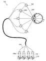
도 3은 장치(10)의 대안의 실시예를 예시한다. 도 3의 장치(100)의 배열 및 작동은, 도 1의 장치(10)와 본질적으로 동일하며, 단지 차이점은, 광원(116)들이 점원(122)으로부터 멀리 위치된다는 것이다. 도 3에 예시된 바와 같이, 각각의 광원(116)은 광섬유(154)(광 전송 디바이스의 예)의 입력으로 시준 광(20)을 집중시키는 추가의 시준 렌즈(136a)를 포함한다. 각각의 광원(116)으로부터의 광이, 광섬유(154)들을 통해 추가의 시준 렌즈(136b)로 전송되며, 이 렌즈는 점원(122)으로부터 시준 광(120)을 제공한다. 광원(116)들의 배열 및 작동은, 전술된 광원(16)들과 동일하다. 장치(100)는, 눈(14)의 망막(12)을 조사 및 영상화하기 위해서 장치(10)와 동일한 방식으로 작동한다. 아크(18)로부터 멀리 광원(116)들을 위치시키는 것은, 장치(100)의 구조를 단순화하고, 장치(100)의 크기를 감소시키며, 별도로 수납될 수 있는 대형의 시준 광원들의 사용을 허용한다. 이러한 배열체에 의해, 또한, 본 발명은 광원(들) 자체에 의해 초래되는 물리적 제한 없이 시준 광의 입력의 고밀도를 얻을 수 있다.
3 illustrates an alternative embodiment of the
본 발명의 장치(10, 100)가 다면경들과 같은 종래의 레이저 스캐닝 요소들을 필요로 하지 않기 때문에, 본 발명의 장치(10, 100)는, 스캐닝 레이저 검안경(scanning laser ophthalmoscope, SLO)들과 같은 공지된 망막 조사 및 영상화 장치들보다 더 낮은 비용으로 제조될 수 있다. 장치가 공지된 망막 영상화 장치들 보다 더 적은 수의 구성요소들을 사용하기 때문에, 장치(10, 100)는 공지된 망막 영상화 장치들보다 더 컴팩트하게 만들어질 수 있다. 또한, 본 발명의 장치(10, 100)는, 장치의 광학 효율을 증가시키는 더 적은 수의 광학 표면들을 포함한다. 그 결과, 영상 검지기에서의 전체 전력은 공지된 방법들보다 더 높다. 또한, 장치(10, 100)는 "광시야(wide field)" 조사 및 영상화 또는 "협시야(narrow field)" 조사 및 영상화 실행을 가능하게 할 수 있다. 따라서, 장치(10, 100)는 상이한 마켓들에 확장가능하다.
Since the
변경예들 및 개선예들이 본 발명의 범주를 벗어나지 않고 상기에서 만들어질 수 있다. 예컨대, 혈관 조영검사(angiography) 및 자가형광 영상(autofluorescence imaging)과 같은 적용분야에서 통상적임에 따라, 장치(10, 100)가 하나의 파장에서 영상화하고 다른 파장에서 검지함으로써 형광 영상화를 위해 사용될 수 있음이 또한 상정되어야 한다. 따라서, 장치(10, 100)는 망막으로부터 반사된 광 또는 장치의 여기시 망막에 의해 발광된 형광 광(fluorescent light)을 수용함으로써 망막의 영상을 얻을 수 있음이 상정되어야 한다. 또한, 장치(10, 100)가 반사 및 형광 영상화 및 치료의 조합을 사용할 수 있다.
Modifications and improvements can be made above without departing from the scope of the present invention. As is common in applications such as angiography and autofluorescence imaging, for example,
게다가, 발광기(28) 및 검지기(30)가 단일 시준 렌즈(36)에 의해 작동되는 것으로 상기에서 예시 및 기재되어 있지만, 발광기(28) 및 검지기(30)가, 단일 광 경로 내로 이들을 조합하기 위해서 렌즈들 이후에 위치되는 빔 분할기 등을 갖는 독립적인 렌즈를 포함할 수 있음이 상정되어야 한다.
In addition, although the
또한, 복수 개의 광원(16)들이 반경(24)을 갖는 아크(18) 상에 배열되는 것으로 상기에서 예시 및 기재되어 있지만, 아크(18)가 반드시 원형일 필요는 없음이 상정되어야 한다. 점원(22)으로부터 시준 광이 형상의 중심점을 향해 지향되고, 그리고 사용시, 이러한 형상의 중심점이 눈(14)의 동공점(40)과 일치하는 한, 복수 개의 광원(16)들은 임의의 적합한 형상으로 배열될 수 있다. 예컨대, 아크(18)는 타원형, 또는 임의의 적합한 비원형 형상일 수 있다.
Further, although a plurality of
게다가, 각각의 광원(16, 116)이 단일 발광기(28)를 포함하는 것으로 상기에 예시 및 기재되어 있지만, 각각의 광원(16, 116)은 상이한 파장들의 하나 또는 그 초과의 발광기들을 포함할 수 있음이 상정되어야 한다.
In addition, although each
또한, 아크(18)의 중심이 눈(14)의 동공점(40)과 일치하는 것으로 상기에 예시 및 기재되어 있지만, 아크(18)의 중심이 일반적으로 눈(14)의 동공점(40) 둘레에 위치될 수 있음이 상정되어야 한다.
Further, although the center of the
게다가, 장치(10, 100)가 광원(16, 116)들의 단일 아크를 포함하고, 장치(10, 100)가 망막(12)의 표면을 조사 및 영상화하기 위해서 축(50)을 중심으로 회전되는 것으로 상기에 예시 및 기재되어 있지만, 본 발명의 대체 실시예에서, 장치(10, 100)는, 복수 개의 동심으로 정렬된 아크들에 놓이는 복수 개의 시준 점원들을 포함할 수 있음이 상정되어야 한다. 이러한 배열체에서, 각각의 점원으로부터의 시준 광은, 중심점을 향해 각각의 아크의 반경을 따라 반경 방향으로 내측방으로 지향된다. 사용시, 각각의 아크의 중심점이 눈의 동공점과 실질적으로 일치하도록 장치(10, 100)가 배열됨으로써, 망막을 조사하기 위해서 각각의 아크 상에 각각의 점원으로부터 눈의 동공점을 통해 시준 광이 투과된다. 이러한 형태의 장치(10, 100)는 각각의 점원으로부터 중심점을 통해 그리고 망막으로 시준 광을 지향시키고 반사된 광을 검지하기 위한 2 차원 반구형 조사 및 검지 표면의 형상을 취한다.
In addition,
또한, 상기에서, 장치(10, 100)가 눈의 망막(12)의 조사 및 영상화를 위한 것으로 기재되어 있지만, 장치(10, 100)가 적절한 파장 및/또는 전력의 시준 광을 망막(12)에 조사함으로써 망막(12) 치료를 실행하기 위해 사용될 수 있음이 또한 상정되어야 한다. 망막(12) 치료는 다음의 단계들을 포함할 수 있다:In addition, while the
(i) 치료를 위해 망막의 영역(region)을 식별함,(i) identify the region of the retina for treatment,
(ii) 영상화 시스템에 연결된 치료 계획을 통해 처리 면적(area)의 크기를 지정함(specifying), 및(ii) specifying the size of the area through a treatment plan connected to the imaging system, and
(iii) 영상화 소스(들)에 대한 공통 입력 경로를 경유하여 단일 또는 다중 사이트들에 치료 조사를 전달하기 위해서 전체적으로 수동 제어 또는 미리 지정된 자동 제어 중 어느 하나로 치료를 가이드함. 이는, 영상화 시스템으로부터 유도된 치료 계획과 치료 지형(geography) 사이의 상관관계를 제공한다. 망막(12) 치료는 또한, 치료중 망막(12)의 영상을 보는 단계 및/또는 치료가 성공적인지를 확인하기 위해서 망막의 재영상화 단계의 선택적인 단계들을 포함할 수 있다.
(iii) Guide treatment to either totally manual control or pre-specified automatic control to deliver treatment investigations to single or multiple sites via a common input path to the imaging source (s). This provides a correlation between the treatment plan derived from the imaging system and the treatment geography.
즉, 본 발명은, 망막 치료에 사용하는 시준 광을 망막에 조사하기 위한 장치를 또한 제공한다. 본 발명은, 또한 망막을 치료하기 위해 시준 광을 망막에 조사하기 위한 방법을 제공한다.
That is, the present invention also provides an apparatus for irradiating the retina with collimation light for use in the treatment of the retina. The invention also provides a method for irradiating collimated light to the retina to treat the retina.
게다가, 상기에서 예시 및 기재된 실시예에서 장치(10, 100)가 복수 개의 광원(16, 116)들을 포함하고 각각의 광원(16, 116)이 점원(22, 122)으로부터 시준 광을 제공하고 있지만, 장치(10, 100)가 단지 단일 광원만을 포함할 수 있고, 이러한 단일 광원이 복수 개의 점원(22, 122)들에 시준 광을 제공할 수 있음이 상정되어야 한다. 이러한 배열체에서, 단일 광원으로부터의 시준 광은 점원에 시준 광을 제공하는 다수의 채널들로 분할될 수 있다.
Furthermore, in the embodiment illustrated and described above, the
Claims (26)
하나 이상의 광원(light source)을 포함하며,
상기 하나 이상의 광원은, 복수 개의 점원(point source)들로부터 시준 광(collimated light)을 제공하도록 구성되며,
각각의 점원은 아크 상에 놓이며,
상기 하나 이상의 광원은, 아크의 중심점을 향해 아크의 반경을 따라 각각의 점원으로부터 시준 광을 지향시키도록 구성되며,
사용시, 상기 장치는, 아크의 중심점이 눈의 동공점과 실질적으로 일치하도록 배열됨으로써, 망막을 조사하기 위해서 점원으로부터 눈의 동공점을 통해 시준 광이 투과(transmitted)되는,
눈의 망막을 조사하는 장치.
A device for illuminating the retina of the eye,
One or more light sources,
The one or more light sources are configured to provide collimated light from a plurality of point sources,
Each clerk is placed on the arc,
The at least one light source is configured to direct collimating light from each point source along the arc radius towards the center point of the arc,
In use, the device is arranged such that the center point of the arc is substantially coincident with the pupil point of the eye, whereby collimating light is transmitted from the point source through the eye pupil point to illuminate the retina,
Device for irradiating the retina of the eye.
상기 장치는 복수 개의 광원들을 포함하고,
각각의 광원은 각각의 점원으로부터 시준 광을 제공하도록 구성되는,
눈의 망막을 조사하는 장치.
The method of claim 1,
The apparatus includes a plurality of light sources,
Each light source is configured to provide collimation light from a respective point source,
Device for irradiating the retina of the eye.
상기 아크의 반경은, 3mm 내지 500mm 사이인,
눈의 망막을 조사하는 장치.
3. The method according to claim 1 or 2,
The radius of the arc is between 3mm and 500mm,
Device for irradiating the retina of the eye.
상기 각각의 광원은 하나 또는 그 초과의 상이한 파장들의 광원들을 포함하는,
눈의 망막을 조사하는 장치.
The method according to claim 2 or 3,
Each light source comprises one or more different wavelengths of light sources,
Device for irradiating the retina of the eye.
상기 각각의 광원은, 제공된 광의 파장이 가변적이도록 구성되는,
눈의 망막을 조사하는 장치.
5. The method according to any one of claims 2 to 4,
Wherein each light source is configured such that the wavelength of the provided light is variable,
Device for irradiating the retina of the eye.
상기 각각의 광원은, 제공된 광의 전력이 가변적이도록 구성되는,
눈의 망막을 조사하는 장치.
6. The method according to any one of claims 2 to 5,
Wherein each light source is configured such that the power of the provided light is variable,
Device for irradiating the retina of the eye.
상기 각각의 광원은 점원에 또는 점원에 인접하게 위치되는,
눈의 망막을 조사하는 장치.
7. The method according to any one of claims 2 to 6,
Each said light source is located at or adjacent to the point source,
Device for irradiating the retina of the eye.
상기 각각의 광원은 상기 점원으로부터 시준 광을 제공하기 위해서 시준 렌즈를 포함하는,
눈의 망막을 조사하는 장치.
8. The method according to any one of claims 2 to 7,
Wherein each light source comprises a collimating lens to provide collimating light from the point source;
Device for irradiating the retina of the eye.
상기 각각의 광원은 상기 점원으로부터 멀리 위치되고, 광은 각각의 광원으로부터 광 전송 디바이스를 경유하여 점원으로 전송되는,
눈의 망막을 조사하는 장치.
7. The method according to any one of claims 2 to 6,
Wherein each light source is located far from the point source, and light is transmitted from each light source to the point source via a light transmission device,
Device for irradiating the retina of the eye.
상기 각각의 광원은 독립적으로 작동될 수 있는,
눈의 망막을 조사하는 장치.
10. The method according to any one of claims 2 to 9,
Each said light source can be operated independently,
Device for irradiating the retina of the eye.
상기 장치는, 복수 개의 점원들 및 아크의 중심점에 의해 형성되는 평면에 실질적으로 놓이는 축을 중심으로 회전가능한,
눈의 망막을 조사하는 장치.
11. The method according to any one of claims 1 to 10,
The apparatus is rotatable about an axis substantially lying in the plane defined by the plurality of point sources and the center point of the arc,
Device for irradiating the retina of the eye.
상기 장치는 복수 개의 동심으로 정렬되는 아크들 상에 놓이는 복수 개의 시준 점원들을 포함하는,
눈의 망막을 조사하는 장치.
12. The method according to any one of claims 1 to 11,
The apparatus includes a plurality of collimating clerks lying on a plurality of concentrically aligned arcs,
Device for irradiating the retina of the eye.
상기 각각의 아크는 실질적으로 동일한 반경 및 중심점을 갖는,
눈의 망막을 조사하는 장치.
13. The method of claim 12,
Wherein each arc has substantially the same radius and center point,
Device for irradiating the retina of the eye.
상기 장치는, 망막의 영상을 만들기 위해서 망막으로부터 반사된 광을 검지하는 광 검지기를 더 포함하는,
눈의 망막을 조사하는 장치.
14. The method according to any one of claims 1 to 13,
The apparatus further includes a light detector for detecting light reflected from the retina to make an image of the retina,
Device for irradiating the retina of the eye.
제 2 항 내지 제 13 항 중 어느 한 항에 종속될 때, 각각의 광원은 망막의 영상을 만들기 위해서 망막으로부터 반사된 광을 검지하는 광 검지기를 포함하는,
눈의 망막을 조사하는 장치.
15. The method of claim 14,
When subject to any of claims 2 to 13, each light source comprises a light detector that detects light reflected from the retina to make an image of the retina,
Device for irradiating the retina of the eye.
복수 개의 점원들로부터 시준 광을 제공하도록 구성되는 하나 이상의 광원을 제공하는 단계,
아크 상에 각각의 점원을 배열하는 단계,
아크의 중심점이 눈의 동공점과 실질적으로 일치하도록 장치를 배열하는 단계, 및
아크의 중심점을 향해 아크의 반경을 따라 각각의 점원으로부터 시준 광을 지향시키도록 하나 이상의 광원을 사용하여, 망막을 조사하기 위해서 점원으로부터 눈의 동공점을 통해 시준 광이 투과되는 단계를 포함하는,
눈의 망막을 조사하는 방법.
As a method of examining the retina of the eye,
Providing one or more light sources configured to provide collimating light from the plurality of point sources,
Arranging each point source on the arc,
Arranging the device such that the center point of the arc substantially coincides with the pupil point of the eye, and
Using one or more light sources to direct collimating light from each point source along the radius of the arc towards the center point of the arc, the collimating light being transmitted from the point source through the eye's pupil point to irradiate the retina,
How to investigate the retina of the eye.
상기 장치는 복수 개의 광원들을 포함하고, 각각의 광원은 각각의 점원으로부터 시준 광을 제공하도록 구성되는,
눈의 망막을 조사하는 방법.
17. The method of claim 16,
The apparatus comprises a plurality of light sources, each light source configured to provide collimating light from each point source,
How to investigate the retina of the eye.
각각의 광원은, 제공된 광의 파장이 가변적이도록 구성되며, 상기 방법은 상기 광원으로부터 광의 파장을 변경시키는 추가 단계를 포함하는,
눈의 망막을 조사하는 방법.
The method of claim 17,
Each light source is configured such that the wavelength of the provided light is variable, the method comprising the additional step of changing the wavelength of light from the light source,
How to investigate the retina of the eye.
각각의 광원은, 제공된 광의 전력이 가변적이도록 구성되며, 상기 방법은 상기 광원으로부터 광의 전력을 변경시키는 추가 단계를 포함하는,
눈의 망막을 조사하는 방법.
The method according to claim 17 or 18,
Each light source is configured such that the power of provided light is variable, and the method includes the additional step of changing the power of light from the light source.
How to investigate the retina of the eye.
상기 각각의 광원은 독립적으로 작동가능하며, 상기 방법은 각각의 광원을 순차적으로 작동시키는 추가 단계를 포함하는,
눈의 망막을 조사하는 방법.
20. The method according to any one of claims 17 to 19,
Wherein each light source is independently operable and the method comprises an additional step of sequentially operating each light source,
How to investigate the retina of the eye.
상기 장치는, 복수 개의 점원들 및 아크의 중심점에 의해 형성된 평면에 실질적으로 놓이는 축을 중심으로 회전가능하며, 상기 방법은 망막의 표면을 조사하기 위해서 축을 중심으로 장치를 회전시키는 추가 단계를 포함하는,
눈의 망막을 조사하는 방법.
21. The method according to any one of claims 17 to 20,
The device is rotatable about an axis substantially lying in the plane defined by the plurality of point sources and the center point of the arc, the method comprising the additional step of rotating the device about the axis to irradiate the surface of the retina,
How to investigate the retina of the eye.
상기 방법은, 망막의 영상을 만들기 위해서 망막으로부터 반사된 광을 검지하기 위해서 광 검지기를 제공하고 광 검지기를 사용하는 추가 단계를 포함하는,
눈의 망막을 조사하는 방법.
22. The method according to any one of claims 16 to 21,
The method includes the additional step of providing a light detector and using the light detector to detect light reflected from the retina to make an image of the retina,
How to investigate the retina of the eye.
하나 이상의 광원 및 복수 개의 광 검지기들을 포함하며,
상기 하나 이상의 광원은 복수 개의 점원들로부터 시준 광을 제공하도록 구성되고, 상기 각각의 광 검지기는 망막으로부터 반사된 광을 검지하도록 구성되며,
상기 각각의 점원은 아크 상에 놓이며,
상기 하나 이상의 광원은, 아크의 중심점을 향해 아크의 반경을 따라 각각의 점원으로부터 시준 광을 지향시키도록 구성되며,
사용시, 상기 장치는, 아크의 중심점이 눈의 동공점과 실질적으로 일치하도록 배열됨으로써, 망막을 조사하기 위해서 점원으로부터 눈의 동공점을 통해 시준 광이 투과(transmitted)되고 망막의 영상을 만들기 위해서 광 검지기로 다시 반사되는,
눈의 망막을 영상화하는 장치.
A device for imaging the retina of the eye,
One or more light sources and a plurality of light detectors,
The at least one light source is configured to provide collimated light from a plurality of point sources, each of the light detectors is configured to detect light reflected from the retina,
Each said clerk lies on an arc,
The at least one light source is configured to direct collimating light from each point source along the arc radius towards the center point of the arc,
In use, the device is arranged such that the center point of the arc is substantially coincident with the pupillary point of the eye, whereby collimating light is transmitted from the point source through the eye pupil point to irradiate the retina and the image is made to produce an image of the retina. Reflected back to the detector,
Device for imaging the retina of the eye.
하나 이상의 광원을 포함하며,
상기 하나 이상의 광원은, 복수 개의 점원들로부터 시준 광을 제공하도록 구성되며,
각각의 점원은 아크 상에 놓이며,
상기 하나 이상의 광원은, 아크의 중심점을 향해 아크의 반경을 따라 각각의 점원으로부터 시준 광을 지향시키도록 구성되며,
사용시, 상기 장치는, 아크의 중심점이 눈의 동공점과 실질적으로 일치하도록 배열됨으로써, 점원으로부터 눈의 동공점을 통해 망막으로 시준 광이 투과되는,
시준 광에 의해 눈의 망막을 치료하는 장치.
A device for treating the retina of the eye by collimation light,
One or more light sources,
The one or more light sources is configured to provide collimating light from a plurality of point sources,
Each clerk is placed on the arc,
The at least one light source is configured to direct collimating light from each point source along the arc radius towards the center point of the arc,
In use, the device is arranged such that the center point of the arc substantially coincides with the pupillary point of the eye, such that collimating light is transmitted from the point source to the retina through the pupillary point of the eye,
Device for treating the retina of the eye by collimation light.
복수 개의 점원들로부터 시준 광을 제공하도록 구성되는 하나 이상의 광원을 제공하는 단계,
망막으로부터 반사된 광을 검지하도록 각각 구성되는 복수 개의 광 검지기를 제공하는 단계,
아크 상에 각각의 점원을 배열하는 단계,
아크의 중심점이 눈의 동공점과 실질적으로 일치하도록 장치를 배열하는 단계,
아크의 중심점을 향해 아크의 반경을 따라 각각의 점원으로부터 시준 광을 지향시키도록 하나 이상의 광원을 사용하여, 망막을 조사하기 위해서 점원으로부터 눈의 동공점을 통해 시준 광이 투과되는 단계, 및
망막의 영상을 만들기 위해서 망막으로부터 반사된 광을 검지하도록 각각의 광 검지기를 사용하는 단계를 포함하는,
눈의 망막을 영상화하는 방법.
As a method of imaging the retina of the eye,
Providing one or more light sources configured to provide collimating light from the plurality of point sources,
Providing a plurality of light detectors each configured to detect light reflected from the retina,
Arranging each point source on the arc,
Arranging the device such that the center point of the arc substantially coincides with the pupillary point of the eye,
Using one or more light sources to direct collimating light from each point source along the arc's radius towards the center point of the arc, through which the collimating light is transmitted from the point source through the eye's pupil point to irradiate the retina, and
Using each photodetector to detect light reflected from the retina to produce an image of the retina,
How to image the retina of the eye.
복수 개의 점원들로부터 시준 광을 제공하도록 구성되는 하나 이상의 광원을 제공하는 단계,
아크 상에 각각의 점원을 배열하는 단계,
아크의 중심점이 눈의 동공점과 실질적으로 일치하도록 장치를 배열하는 단계, 및
아크의 중심점을 향해 아크의 반경을 따라 각각의 점원으로부터 시준 광을 지향시키도록 하나 이상의 광원을 사용하여, 점원으로부터 눈의 동공점을 통해 망막으로 시준 광이 투과되는 단계를 포함하는,
시준 광에 의해 눈의 망막을 치료하는 방법.As a method of treating the retina of the eye by collimation light,
Providing one or more light sources configured to provide collimating light from the plurality of point sources,
Arranging each point source on the arc,
Arranging the device such that the center point of the arc substantially coincides with the pupil point of the eye, and
Collimating light from the point source to the retina through the pupil point of the eye, using one or more light sources to direct collimating light from each point source along the radius of the arc towards the center point of the arc,
How to treat the retina of the eye by collimation light.
Applications Claiming Priority (3)
| Application Number | Priority Date | Filing Date | Title |
|---|---|---|---|
| GB1011094.8 | 2010-07-01 | ||
| GBGB1011094.8A GB201011094D0 (en) | 2010-07-01 | 2010-07-01 | Improvements in or relating to ophthalmology |
| PCT/GB2011/051039 WO2012001383A1 (en) | 2010-07-01 | 2011-06-02 | Improvements in or relating to ophthalmology |
Publications (1)
| Publication Number | Publication Date |
|---|---|
| KR20130089637A true KR20130089637A (en) | 2013-08-12 |
Family
ID=42669041
Family Applications (1)
| Application Number | Title | Priority Date | Filing Date |
|---|---|---|---|
| KR1020137001275A KR20130089637A (en) | 2010-07-01 | 2011-06-02 | Improvements in or relating to ophthalmology |
Country Status (13)
| Country | Link |
|---|---|
| US (1) | US9737204B2 (en) |
| EP (1) | EP2587987B1 (en) |
| JP (1) | JP5852111B2 (en) |
| KR (1) | KR20130089637A (en) |
| CN (1) | CN102970918B (en) |
| AU (1) | AU2011273207A1 (en) |
| BR (1) | BR112012033768A2 (en) |
| CA (1) | CA2802906A1 (en) |
| DK (1) | DK2587987T3 (en) |
| ES (1) | ES2700505T3 (en) |
| GB (1) | GB201011094D0 (en) |
| RU (1) | RU2012155220A (en) |
| WO (1) | WO2012001383A1 (en) |
Families Citing this family (5)
| Publication number | Priority date | Publication date | Assignee | Title |
|---|---|---|---|---|
| ES2856025T3 (en) | 2013-06-20 | 2021-09-27 | Cylite Pty Ltd | Ocular metrology using spectral analysis of reflected light wave fronts |
| US10201275B1 (en) | 2016-02-09 | 2019-02-12 | Carl Zeiss Meditec, Inc. | Reflective ultra-wide field fundus imager |
| JP6589020B2 (en) * | 2018-08-01 | 2019-10-09 | 株式会社トプコン | Ophthalmic equipment |
| EP3886678A4 (en) * | 2018-11-28 | 2022-12-14 | Broadspot Imaging Corporation | System for ultra-wide field imaging of the posterior segment |
| US20210263338A1 (en) * | 2020-02-21 | 2021-08-26 | James Copland | WideField Dynamic Aberrometer Measurements for Myopia Control with Customized Contact Lenses |
Family Cites Families (22)
| Publication number | Priority date | Publication date | Assignee | Title |
|---|---|---|---|---|
| US3944341A (en) * | 1972-09-25 | 1976-03-16 | Retina Foundation | Wide-angle ophthalmoscope and fundus camera |
| JPS5938A (en) * | 1982-06-23 | 1984-01-05 | 有限会社 宇津木光学研究所 | Intraocular observing and inspecting apparatus |
| US4666269A (en) * | 1982-08-09 | 1987-05-19 | Canon Kabushiki Kaisha | Ophthalmologic apparatus |
| US5028802A (en) * | 1990-01-11 | 1991-07-02 | Eye Research Institute Of Retina Foundation | Imaging apparatus and methods utilizing scannable microlaser source |
| US5585873A (en) * | 1991-10-11 | 1996-12-17 | Alcon Laboratories, Inc. | Automated hand-held keratometer |
| JPH0661862A (en) | 1992-08-07 | 1994-03-04 | Fujitsu Ltd | Two-signal input deltasigma modulation type a/d converter |
| JP3369623B2 (en) * | 1993-03-16 | 2003-01-20 | 興和株式会社 | Laser scanning ophthalmic imaging device |
| GB9323065D0 (en) * | 1993-11-09 | 1994-01-05 | Besca Ltd | A wide field retinal scanning ophthalmoscope |
| JPH09131322A (en) * | 1995-11-09 | 1997-05-20 | Canon Inc | Fundoscopy device |
| JP3509377B2 (en) * | 1996-04-12 | 2004-03-22 | 株式会社ニコン | Curvature measuring device |
| DE19733995B4 (en) * | 1997-08-06 | 2007-12-13 | Carl Zeiss Meditec Ag | Laser scanning ophthalmoscope |
| US6007202A (en) | 1997-10-23 | 1999-12-28 | Lasersight Technologies, Inc. | Eye illumination system and method |
| US6055322A (en) | 1997-12-01 | 2000-04-25 | Sensor, Inc. | Method and apparatus for illuminating and imaging eyes through eyeglasses using multiple sources of illumination |
| US6547394B2 (en) | 1998-10-20 | 2003-04-15 | Victor J. Doherty | Hand-held ophthalmic illuminator |
| DE29913603U1 (en) | 1999-08-04 | 1999-11-25 | Oculus Optikgeraete Gmbh | Slit projector |
| GB2375679A (en) * | 2001-04-09 | 2002-11-20 | Patrick Kerr | Retinal function camera using plural light wavelengths to produce a retinal function image showing haemoglobin oxygenation. |
| DE102005034829A1 (en) | 2005-07-26 | 2007-02-01 | Leica Microsystems (Schweiz) Ag | Microscope for use in ophthalmology for surgery and diagnosis, has laser diode for emitting coherent light beam bundle for travel along defined illumination beam path, which is modified by spatial light modulator |
| GB2440163A (en) * | 2006-07-15 | 2008-01-23 | Optos Plc | Scanning ophthalmoscope with reduced shear distortion |
| US20080137184A1 (en) | 2006-12-07 | 2008-06-12 | Hopler Mark D | Illumination System for Surgical Microscope |
| JP4829765B2 (en) | 2006-12-08 | 2011-12-07 | キヤノン株式会社 | Image display device and image display system |
| AU2008232319B2 (en) * | 2007-03-28 | 2012-08-09 | Brien Holden Vision Institute | Characterising eye-related optical systems |
| EP2178432A2 (en) * | 2007-07-04 | 2010-04-28 | i-Optics B.V. | Confocal color ophthalmoscope |
-
2010
- 2010-07-01 GB GBGB1011094.8A patent/GB201011094D0/en not_active Ceased
-
2011
- 2011-06-02 ES ES11727747T patent/ES2700505T3/en active Active
- 2011-06-02 WO PCT/GB2011/051039 patent/WO2012001383A1/en active Application Filing
- 2011-06-02 EP EP11727747.5A patent/EP2587987B1/en active Active
- 2011-06-02 RU RU2012155220/14A patent/RU2012155220A/en not_active Application Discontinuation
- 2011-06-02 US US13/805,595 patent/US9737204B2/en active Active
- 2011-06-02 CA CA2802906A patent/CA2802906A1/en not_active Abandoned
- 2011-06-02 BR BR112012033768A patent/BR112012033768A2/en not_active IP Right Cessation
- 2011-06-02 DK DK11727747.5T patent/DK2587987T3/en active
- 2011-06-02 CN CN201180032861.2A patent/CN102970918B/en active Active
- 2011-06-02 JP JP2013517526A patent/JP5852111B2/en active Active
- 2011-06-02 KR KR1020137001275A patent/KR20130089637A/en not_active Application Discontinuation
- 2011-06-02 AU AU2011273207A patent/AU2011273207A1/en not_active Abandoned
Also Published As
| Publication number | Publication date |
|---|---|
| AU2011273207A1 (en) | 2013-01-10 |
| DK2587987T3 (en) | 2018-12-17 |
| GB201011094D0 (en) | 2010-08-18 |
| JP2013530001A (en) | 2013-07-25 |
| EP2587987B1 (en) | 2018-11-07 |
| CN102970918A (en) | 2013-03-13 |
| JP5852111B2 (en) | 2016-02-03 |
| CA2802906A1 (en) | 2012-01-05 |
| US20130128224A1 (en) | 2013-05-23 |
| CN102970918B (en) | 2017-04-12 |
| ES2700505T3 (en) | 2019-02-18 |
| EP2587987A1 (en) | 2013-05-08 |
| WO2012001383A1 (en) | 2012-01-05 |
| US9737204B2 (en) | 2017-08-22 |
| BR112012033768A2 (en) | 2018-02-27 |
| RU2012155220A (en) | 2014-08-10 |
Similar Documents
| Publication | Publication Date | Title |
|---|---|---|
| US10335028B2 (en) | Ophthalmology | |
| US9743831B2 (en) | Retinal imaging apparatus and method | |
| JP5914473B2 (en) | Improvement in ophthalmology or ophthalmology | |
| KR20130089637A (en) | Improvements in or relating to ophthalmology | |
| JP2013532039A5 (en) |
Legal Events
| Date | Code | Title | Description |
|---|---|---|---|
| WITN | Application deemed withdrawn, e.g. because no request for examination was filed or no examination fee was paid |