KR20130065648A - Apparatus and method for gas tight secondary stave support - Google Patents
Apparatus and method for gas tight secondary stave support Download PDFInfo
- Publication number
- KR20130065648A KR20130065648A KR1020127028367A KR20127028367A KR20130065648A KR 20130065648 A KR20130065648 A KR 20130065648A KR 1020127028367 A KR1020127028367 A KR 1020127028367A KR 20127028367 A KR20127028367 A KR 20127028367A KR 20130065648 A KR20130065648 A KR 20130065648A
- Authority
- KR
- South Korea
- Prior art keywords
- stave
- support
- furnace
- pipe
- water pipe
- Prior art date
Links
- 238000000034 method Methods 0.000 title claims description 47
- 230000001681 protective effect Effects 0.000 claims abstract description 102
- XLYOFNOQVPJJNP-UHFFFAOYSA-N water Substances O XLYOFNOQVPJJNP-UHFFFAOYSA-N 0.000 claims abstract description 102
- 238000007789 sealing Methods 0.000 claims description 51
- 238000005219 brazing Methods 0.000 claims description 21
- 238000003466 welding Methods 0.000 claims description 20
- 238000005476 soldering Methods 0.000 claims description 14
- 238000005266 casting Methods 0.000 claims description 5
- 238000004891 communication Methods 0.000 claims description 2
- 239000002184 metal Substances 0.000 claims 1
- 239000000463 material Substances 0.000 description 23
- 239000007789 gas Substances 0.000 description 20
- UGFAIRIUMAVXCW-UHFFFAOYSA-N Carbon monoxide Chemical compound [O+]#[C-] UGFAIRIUMAVXCW-UHFFFAOYSA-N 0.000 description 10
- 229910002091 carbon monoxide Inorganic materials 0.000 description 10
- 229910052802 copper Inorganic materials 0.000 description 7
- 239000010949 copper Substances 0.000 description 7
- RYGMFSIKBFXOCR-UHFFFAOYSA-N Copper Chemical group [Cu] RYGMFSIKBFXOCR-UHFFFAOYSA-N 0.000 description 6
- 229910001018 Cast iron Inorganic materials 0.000 description 5
- 230000015572 biosynthetic process Effects 0.000 description 3
- 239000011440 grout Substances 0.000 description 2
- 238000005304 joining Methods 0.000 description 2
- 229910000831 Steel Inorganic materials 0.000 description 1
- 238000001816 cooling Methods 0.000 description 1
- 150000001879 copper Chemical class 0.000 description 1
- 230000009970 fire resistant effect Effects 0.000 description 1
- 238000009434 installation Methods 0.000 description 1
- 238000010297 mechanical methods and process Methods 0.000 description 1
- 239000007787 solid Substances 0.000 description 1
- 229910001220 stainless steel Inorganic materials 0.000 description 1
- 239000010935 stainless steel Substances 0.000 description 1
- 239000010959 steel Substances 0.000 description 1
Images


Classifications
-
- F—MECHANICAL ENGINEERING; LIGHTING; HEATING; WEAPONS; BLASTING
- F27—FURNACES; KILNS; OVENS; RETORTS
- F27D—DETAILS OR ACCESSORIES OF FURNACES, KILNS, OVENS, OR RETORTS, IN SO FAR AS THEY ARE OF KINDS OCCURRING IN MORE THAN ONE KIND OF FURNACE
- F27D9/00—Cooling of furnaces or of charges therein
-
- B—PERFORMING OPERATIONS; TRANSPORTING
- B23—MACHINE TOOLS; METAL-WORKING NOT OTHERWISE PROVIDED FOR
- B23P—METAL-WORKING NOT OTHERWISE PROVIDED FOR; COMBINED OPERATIONS; UNIVERSAL MACHINE TOOLS
- B23P19/00—Machines for simply fitting together or separating metal parts or objects, or metal and non-metal parts, whether or not involving some deformation; Tools or devices therefor so far as not provided for in other classes
-
- C—CHEMISTRY; METALLURGY
- C21—METALLURGY OF IRON
- C21B—MANUFACTURE OF IRON OR STEEL
- C21B7/00—Blast furnaces
- C21B7/10—Cooling; Devices therefor
-
- F—MECHANICAL ENGINEERING; LIGHTING; HEATING; WEAPONS; BLASTING
- F27—FURNACES; KILNS; OVENS; RETORTS
- F27B—FURNACES, KILNS, OVENS, OR RETORTS IN GENERAL; OPEN SINTERING OR LIKE APPARATUS
- F27B7/00—Rotary-drum furnaces, i.e. horizontal or slightly inclined
- F27B7/14—Rotary-drum furnaces, i.e. horizontal or slightly inclined with means for agitating or moving the charge
-
- F—MECHANICAL ENGINEERING; LIGHTING; HEATING; WEAPONS; BLASTING
- F27—FURNACES; KILNS; OVENS; RETORTS
- F27D—DETAILS OR ACCESSORIES OF FURNACES, KILNS, OVENS, OR RETORTS, IN SO FAR AS THEY ARE OF KINDS OCCURRING IN MORE THAN ONE KIND OF FURNACE
- F27D1/00—Casings; Linings; Walls; Roofs
- F27D1/12—Casings; Linings; Walls; Roofs incorporating cooling arrangements
-
- Y—GENERAL TAGGING OF NEW TECHNOLOGICAL DEVELOPMENTS; GENERAL TAGGING OF CROSS-SECTIONAL TECHNOLOGIES SPANNING OVER SEVERAL SECTIONS OF THE IPC; TECHNICAL SUBJECTS COVERED BY FORMER USPC CROSS-REFERENCE ART COLLECTIONS [XRACs] AND DIGESTS
- Y10—TECHNICAL SUBJECTS COVERED BY FORMER USPC
- Y10T—TECHNICAL SUBJECTS COVERED BY FORMER US CLASSIFICATION
- Y10T29/00—Metal working
- Y10T29/49—Method of mechanical manufacture
- Y10T29/49826—Assembling or joining
- Y10T29/49947—Assembling or joining by applying separate fastener
Abstract
본 발명은 노 스테이브의 외부에 있는 물 파이프의 제 1 부분과 노 쉘 벽의 외부에 있는 물 파이프의 제 2 부분을 가진 물 파이프를 포함하는 노 스테이브용 이차 스테이브 지지부에 관한 것으로서, 상기 이차 스테이브 지지부는: 제 1 단부와 제 2 단부를 가진 보호 파이프를 포함하며, 상기 보호 파이프는 스테이브에 가장 가까이 위치된 제 1 단부와 물 파이프 주위에 동축구성 방식으로 배열되고; 물 파이프의 제 3 부분과 보호 파이프의 제 1 단부 사이에 배치된 제 1 기밀식 밀봉부를 포함하며, 상기 제 1 기밀식 밀봉부는 노 쉘 벽 내부로부터 나온 가스가 보호 파이프와 물 파이프 사이의 환형 공간 내로 유입되는 것을 방지하는 특징을 가진다.The present invention relates to a secondary stave support for a furnace stave comprising a water pipe having a first portion of a water pipe external to the furnace stave and a second portion of a water pipe external to the furnace shell wall. The secondary stave support comprises: a protective pipe having a first end and a second end, said protective pipe being arranged coaxially around the water pipe and the first end located closest to the stave; A first hermetic seal disposed between the third portion of the water pipe and the first end of the protection pipe, wherein the first hermetic seal includes an annular space between the protection pipe and the water pipe from which gas from inside the furnace shell wall It is characterized by preventing the inflow into.
Description
본 발명은, 2010년 3월 30일에 출원되고 발명의 명칭이 "Apparatus And Method For Gas Tight Secondary Copper Stave Support"인 미국 가특허출원번호 61/318,977호를 기초로 우선권을 주장하고 있으며, 이 미국특허출원은 전체적으로 본 명세서에서 참조문헌으로서 인용된다.The present invention claims priority based on U.S. Provisional Patent Application No. 61 / 318,977, filed Mar. 30, 2010, entitled "Apparatus And Method For Gas Tight Secondary Copper Stave Support". Patent applications are incorporated herein by reference in their entirety.
본 발명은 용광로(blast furnace) 및 그 외의 다른 야금로(metallurgical furnace)의 노 쉘(furnace)을 냉각하기 위한 장치와 방법에 관한 것이다.The present invention relates to an apparatus and a method for cooling furnace furnaces of blast furnaces and other metallurgical furnaces.
주철 스테이브(cast iron stave)는 오랜 세월동안 각각의 물 공급 및 배출 파이프 주위에서 캐스트-인 보호 파이프(cast-in protection pipe)와 함께 사용되어 왔다. 상기 물 공급 및 배출 파이프는 스테이브를 고정하는 볼트(bolt)에 이차 지지부(secondary support)로서 작용하기 위해 다양한 방법에 의해 노 쉘(furnace shell)에 견고하게 고정되었다. 이러한 캐스트-인 보호 파이프는 종종 노 가스가 배출되는 것을 방지하기 위해 밀봉 링을 통해 쉘의 외부에 있는 물 파이프에 용접되었다. 이는 가스가 보호 파이프와 물 파이프 사이의 영역에 유입되는 것을 방지하기 위해 캐스팅 재료(casting material)에 충분한 결합을 형성할 수 없을 수도 있기 때문에 필요했었다. 또한, 오랜 작동 기간 후에는, 주철 스테이브는 통상적으로 균열이 생겨서 가스가 상기 영역에 유입될 수 있게 할 수도 있다.Cast iron stave has been used for many years with cast-in protection pipes around each water supply and discharge pipe. The water supply and discharge pipes were firmly fixed to the furnace shell by various methods to act as secondary support to the bolts securing the stave. These cast-in protection pipes were often welded to the water pipes on the outside of the shell through a seal ring to prevent furnace gas emissions. This was necessary because it may not be possible to form sufficient bonds to the casting material to prevent gas from entering the region between the protective pipe and the water pipe. In addition, after a long period of operation, the cast iron stave may typically crack and allow gas to enter the region.
주철 스테이브 후에 구리 스테이브(copper stave)가 개발되었다. 원래, 이러한 구리 스테이브는 구리 빌릿(copper billet)이 드릴링되는 드릴링(drilled) 및 플러깅(plugged) 디자인으로서 개발되었는데, 물 파이프는 공급과 배출을 위해 뒷면(back)에 용접되었다. 이 용접 연결부에서 과거 20년 동안 여러 문제가 발생하였다. 이러한 스테이브는 쉘을 통해 돌출하지 않는 용접된 보호 파이프들과 함께 제조되었다. 통상적인 디자인으로 인해, 용접된 보호 파이프는 노 내부에서 부유할(float) 수 있게 되고그 주변에는 찌그러질 수 있는 재료(crushable material)로 둘러싸이며 그 주변에는 주조가능한 재료(castable material)가 부어진다(pouring). 물 파이프는 쉘을 통해 돌출되며 가요성의 보정기(flexible compensator)에 의해 결부된다(attached). 따라서, 이차 지지 메커니즘(secondary support mechanism)으로서 작용하기 위해 구리 스테이브에 하나 이상의 지지 핀(support pin)이 추가된다. 이러한 가요성 보정기는 빈번히 실패하는 것으로 알려져 있다. 설치 후에 보정기를 통해 노 가스가 누출하는 여러 경우가 있다.After the cast iron stave a copper stave was developed. Originally, this copper stave was developed as a drilled and plugged design in which copper billets were drilled, where water pipes were welded to the back for supply and discharge. Several problems have arisen in this welded joint over the past 20 years. This stave was manufactured with welded protective pipes that did not protrude through the shell. Due to the conventional design, the welded protective pipe can float inside the furnace, surrounded by crushable material and poured castable material around it. (pouring). The water pipe protrudes through the shell and is attached by a flexible compensator. Thus, one or more support pins are added to the copper stave to act as a secondary support mechanism. Such flexible compensators are known to fail frequently. There are many cases where furnace gas leaks through the calibrator after installation.
본 발명의 이차 스테이브 지지부는 주철, 주조된 구리(cast copper) 또는 드릴링되고 플러깅된 스테이브 내에 일체로 구성될 수 있다. 스테이브용 이차 지지부 및 노 가스 밀봉부(furnace gas seal)로서 보호 파이프를 사용하고 물 밀봉부(water seal)로서 물 파이프를 사용하여 물 파이프를 보호 파이프 내에서 자유로이 이동하게 유지하는 것이 바람직할 것이다.The secondary stave support of the present invention may be integrally constructed within cast iron, cast copper or drilled and plugged staves. It would be desirable to use the protective pipe as a secondary support and furnace gas seal for the stave and the water pipe as the water seal to keep the water pipe freely moving in the protective pipe. .
본 발명의 상기 이점들과 그 외의 이점들은 바람직한 구체예(들)을 상세하게 기술한 하기 설명을 참조함으로써 이해될 것이다.These and other advantages of the present invention will be understood by reference to the following description which sets forth preferred embodiment (s) in detail.
본 발명의 첫 번째 형태에서, 본 발명은 노 스테이브(furnace stave)의 외부에 있는 물 파이프의 제 1 부분과 노 쉘 벽(furnace shell wall)의 외부에 있는 물 파이프의 제 2 부분을 가진 물 파이프를 포함하는 노 스테이브용 이차 스테이브 지지부를 제공하는데, 상기 이차 스테이브 지지부는 제 1 단부와 제 2 단부를 가진 보호 파이프를 포함하며, 상기 보호 파이프는 스테이브에 가장 가까이 위치된 제 1 단부와 물 파이프 주위에 동축구성 방식으로 배열되고, 상기 이차 스테이브 지지부는 물 파이프의 제 3 부분과 보호 파이프의 제 1 단부 사이에 배치된 제 1 기밀식 밀봉부를 포함하며, 상기 제 1 기밀식 밀봉부는 노 쉘 벽 내부로부터 나온 가스가 보호 파이프와 물 파이프 사이의 환형 공간 내로 유입되는 것을 방지한다.In a first aspect of the invention, the invention relates to a water having a first portion of a water pipe on the outside of a furnace stave and a second portion of a water pipe on the outside of a furnace shell wall. A secondary stave support for a furnace stave comprising a pipe, the secondary stave support comprising a protective pipe having a first end and a second end, the protective pipe being the first positioned closest to the stave. Arranged coaxially around the end and the water pipe, wherein the secondary stave support includes a first hermetic seal disposed between the third portion of the water pipe and the first end of the protective pipe; The seal prevents gas from inside the furnace shell wall into the annular space between the protective pipe and the water pipe.
이차 스테이브 지지부의 또 다른 형태에 따르면, 노 쉘 벽의 외부에 있는 물 파이프의 제 2 부분은 어떠한 수단 또는 구성으로도 보호 파이프에 직접 또는 간접적으로 연결되지 않는다.According to another form of secondary stave support, the second part of the water pipe outside of the furnace shell wall is not directly or indirectly connected to the protective pipe by any means or configuration.
이차 스테이브 지지부의 또 다른 형태에 따르면, 물 파이프의 제 1 부분 또는 제 2 부분 중 어느 부분도 어떠한 수단 또는 구성으로도 보호 파이프에 직접 또는 간접적으로 연결되지 않는다.According to another form of secondary stave support, neither the first part nor the second part of the water pipe is directly or indirectly connected to the protective pipe by any means or configuration.
이차 스테이브 지지부의 또 다른 형태에서, 보호 파이프와 물 파이프 사이의 환형 공간은 빈 공간이며 보호 파이프의 제 2 단부는 개방되어 있다.In another form of secondary stave support, the annular space between the protective pipe and the water pipe is an empty space and the second end of the protective pipe is open.
이차 스테이브 지지부의 또 다른 형태에서, 보호 파이프의 제 1 단부는 외부를 향해 벌어져 있으며(flared outwards) 물 파이프의 제 3 부분과 함께 스테이브 내에 주조된다(cast).In another form of secondary stave support, the first end of the protective pipe is flared outwards and cast into the stave with a third portion of the water pipe.
이차 스테이브 지지부의 또 다른 형태에서, 제 1 기밀식 밀봉부는 스테이브 내에 배열된다.In another form of secondary stave support, the first hermetic seal is arranged in the stave.
이차 스테이브 지지부의 또 다른 형태에서, 제 1 기밀식 밀봉부는 스테이브의 일부분으로서 형성된다.In another form of secondary stave support, the first hermetic seal is formed as part of the stave.
이차 스테이브 지지부의 또 다른 형태에서, 제 1 기밀식 밀봉부는 스테이브의 외부에 배열된다.In another form of secondary stave support, the first hermetic seal is arranged external to the stave.
이차 스테이브 지지부의 또 다른 형태에서, 제 1 기밀식 밀봉부는 납땜(soldering), 브레이징(brazing), 스레딩(threading), 또는 용접부(welding)로 구성된 군으로부터 선택되고 물 파이프의 제 3 부분과 보호 파이프의 제 1 단부 사이에 형성된 연결부를 포함한다.In another form of secondary stave support, the first hermetic seal is selected from the group consisting of soldering, brazing, threading, or welding and protects with a third portion of the water pipe. A connection formed between the first end of the pipe.
또 다른 형태에서, 이차 스테이브 지지부는 스테이브의 외측 부분과 보호 파이프 사이에 형성된 제 2 기밀식 밀봉부를 추가로 포함하며, 상기 제 2 기밀식 밀봉부는 보호 파이프의 제 1 단부와 제 2 단부 사이에 있는 보호 파이프 위에 배열된다.In another form, the secondary stave support further comprises a second hermetic seal formed between the outer portion of the stave and the protective pipe, the second hermetic seal between the first and second ends of the protective pipe. Is arranged on the protective pipe in the.
이차 스테이브 지지부의 또 다른 형태에서, 제 2 기밀식 밀봉부는 납땜, 브레이징, 스레딩, 또는 용접부로 구성된 군으로부터 선택된 연결부를 포함한다. 이차 스테이브 지지부의 또 다른 형태에서, 보호 파이프는 노 쉘 벽에 직접 연결된다.In another form of secondary stave support, the second hermetic seal includes a connection selected from the group consisting of soldering, brazing, threading, or welding. In another form of secondary stave support, the protective pipe is connected directly to the furnace shell wall.
또 다른 형태에서, 이차 스테이브 지지부는 노 쉘 벽에 연결된 밀폐 플레이트(closure plate)를 추가로 포함하고, 보호 파이프는 상기 밀폐 플레이트 내에 있는 구멍(opening)을 통해 연장되고 밀폐 플레이트에 연결된다.In another form, the secondary stave support further comprises a closure plate connected to the furnace shell wall, wherein the protective pipe extends through an opening in the closure plate and is connected to the closure plate.
또 다른 형태에서, 이차 스테이브 지지부는 노 쉘 벽에 연결된 견고한 보정기(rigid compensator)를 추가로 포함하고, 보호 파이프는 상기 견고한 보정기 내에 있는 구멍을 통해 연장되고 견고한 보정기에 연결된다.In another form, the secondary stave support further includes a rigid compensator connected to the furnace shell wall, the protective pipe extending through a hole in the rigid compensator and connected to the rigid compensator.
이차 스테이브 지지부의 또 다른 형태에서, 물 파이프는 제 4 부분을 추가로 포함하고 물 파이프의 제 3 부분과 제 4 부분은 스테이브와 일체로 주조된다(integrally cast).In another form of secondary stave support, the water pipe further comprises a fourth portion and the third and fourth portions of the water pipe are integrally cast with the stave.
이차 스테이브 지지부의 추가적인 형태에서, 물 파이프의 제 3 부분은 스테이브 내에 배열되고 납땜, 브레이징, 스레딩, 또는 용접부로 구성된 군으로부터 선택된 연결부에 의해 스테이브에 연결된다.In a further form of secondary stave support, the third portion of the water pipe is arranged in the stave and connected to the stave by a connection selected from the group consisting of soldering, brazing, threading, or welding.
이차 스테이브 지지부의 추가적인 형태에서, 제 1 기밀식 밀봉부는 납땜, 브레이징, 스레딩, 또는 용접부로 구성된 군으로부터 선택되고 물 파이프의 제 3 부분의 외측 부분과 보호 파이프의 제 1 단부의 내측 부분 사이에 형성된 연결부를 포함한다.In a further form of secondary stave support, the first hermetic seal is selected from the group consisting of soldering, brazing, threading, or welding, and between the outer part of the third part of the water pipe and the inner part of the first end of the protective pipe. It includes a connection formed.
또 다른 형태에서, 이차 스테이브 지지부는 스테이브의 외측 부분과 보호 파이프의 제 1 단부의 외측 표면 사이에 형성된 제 2 기밀식 밀봉부를 추가로 포함한다.In another form, the secondary stave support further includes a second hermetic seal formed between the outer portion of the stave and the outer surface of the first end of the protective pipe.
또 다른 형태에서, 이차 스테이브 지지부는 노 쉘 벽에 연결된 견고한 보정기를 추가로 포함하고, 보호 파이프의 제 2 단부는 견고한 보정기 내에 있는 구멍를 통해 연장되며 견고한 보정기에 연결된다.In another form, the secondary stave support further includes a rigid compensator connected to the furnace shell wall, the second end of the protective pipe extending through a hole in the rigid compensator and connected to the rigid compensator.
이차 스테이브 지지부의 또 다른 형태에서, 제 1 기밀식 밀봉부는 물 파이프의 제 3 부분과 보호 파이프의 제 1 단부에 연결된 밀봉 링을 포함한다.In another form of secondary stave support, the first hermetic seal includes a sealing ring connected to the third portion of the water pipe and the first end of the protective pipe.
이차 스테이브 지지부의 추가적인 형태에서, 물 파이프의 제 3 부분과 보호 파이프의 제 1 단부에 연결된 밀봉 링을 포함하는 제 1 기밀식 밀봉부는 스테이브 내에 주조된다.In a further form of secondary stave support, a first hermetic seal comprising a sealing ring connected to the third portion of the water pipe and the first end of the protective pipe is cast in the stave.
이차 스테이브 지지부의 또 다른 형태에서, 밀봉 링은 큰 수치를 가진 단부로부터 작은 수치를 가진 단부로 테이퍼구성된다(taper). 이차 스테이브 지지부의 또 다른 형태에서, 밀봉 링의 일부분 이상은 스테이브 내에 주조된다. 이차 스테이브 지지부의 또 다른 형태에서, 적어도, 밀봉 링의 큰 수치를 가진 단부가 스테이브 내에 주조된다.In another form of secondary stave support, the sealing ring tapers from the end with the larger value to the end with the smaller value. In another form of secondary stave support, at least a portion of the sealing ring is cast into the stave. In another form of secondary stave support, at least the end with the large value of the sealing ring is cast into the stave.
이차 스테이브 지지부의 추가적인 형태에서, 밀봉 링의 큰 수치를 가진 단부는 스테이브 내에 주조되고 밀봉 링의 작은 수치를 가진 단부는 스테이브로부터 돌출된다. 또 다른 형태에서, 이차 스테이브 지지부는 밀봉 링의 작은 수치를 가진 단부와 보호 파이프의 제 1 단부의 외측 표면 사이에 제 2 기밀식 밀봉부를 추가로 포함한다. 이차 스테이브 지지부의 또 다른 형태에서, 제 1 기밀식 밀봉부는 스테이브의 외부에 배열된다.In a further form of secondary stave support, the large valued end of the sealing ring is cast into the stave and the small valued end of the sealing ring protrudes from the stave. In another form, the secondary stave support further comprises a second hermetic seal between the end with the small value of the sealing ring and the outer surface of the first end of the protective pipe. In another form of secondary stave support, the first hermetic seal is arranged external to the stave.
또 다른 형태에서, 본 발명은 노 쉘 벽의 외부의 한 부분을 가진 물 파이프를 포함하는 노 스테이브용 이차 스테이브 지지부를 제공하기 위한 방법을 제공하는데, 상기 방법은 보호 파이프의 제 1 단부를 스테이브의 근위부분에 위치된 동축구성의 내부 물 파이프에 기밀방식으로(gas-tightly) 결부시키는 단계 및 보호 파이프의 제 2 단부를 노 쉘 벽에 기밀방식으로 결부시켜 제 2 단부가 노 쉘 벽의 외부에 있는 물 파이프 부분과 물리적으로 소통되지 않는 상태에 있도록 하는 단계를 포함한다.In another aspect, the present invention provides a method for providing a secondary stave support for a furnace stave comprising a water pipe having a portion of the exterior of the furnace shell wall, the method comprising: Gas-tightly attaching to the coaxial inner water pipe located proximal to the stave and sealing the second end of the protective pipe to the furnace shell wall so that the second end is the furnace shell wall. And in a state of not being in physical communication with the portion of the water pipe that is external to the device.
노 스테이브용 이차 스테이브 지지부를 제공하기 위한 방법의 또 다른 형태에서, 제 1 단부를 결부시키는 방법은 용접, 브레이징, 스레딩 또는 캐스팅으로부터 선택된다.In another form of method for providing a secondary stave support for a furnace stave, the method of joining the first end is selected from welding, brazing, threading or casting.
노 스테이브용 이차 스테이브 지지부를 제공하기 위한 방법의 또 다른 형태에서, 제 2 단부를 결부시키는 방법은 용접, 브레이징, 스레딩 또는 캐스팅으로부터 선택된다.In another form of method for providing a secondary stave support for a furnace stave, the method of joining the second end is selected from welding, brazing, threading or casting.
본 발명이 쉽게 이해될 수 있고 용이하게 실시될 수 있도록 하기 위하여, 이제, 본 발명은 하기 도면들을 참조하여 오직 비-제한적이고 예시적으로 기술될 것이다.
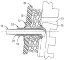
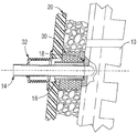
도 1은 일산화탄소 및/또는 그 외의 가스가 누출되는 것을 방지하기 위해 물 파이프와 물 보호 파이프 사이의 환형 공간 내에 내화성 또는 그라우트 재료를 이용하는 밀폐 플레이트 지지부를 가진 물 보호 파이프를 포함하는 종래의 캐스트 스테이브(cast stave) 이차 지지부를 도시한 측면 횡단면도이다.
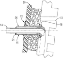
도 2는 일산화탄소 및/또는 그 외의 가스가 누출되는 것을 방지하기 위해 물 파이프와 물 보호 파이프 사이의 환형 공간을 밀봉하도록 밀봉 링을 이용하는 밀폐 플레이트 지지부를 가진 물 보호 파이프를 포함하는 종래의 캐스트 스테이브 이차 지지부를 도시한 측면 횡단면도이다.
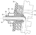
도 3은 일산화탄소 및/또는 그 외의 가스가 누출되는 것을 방지하기 위해 밀봉 링과 견고한 보정기(compensator)를 가진 물 보호 파이프를 포함하는 종래의 캐스트 스테이브 이차 지지부를 도시한 측면 횡단면도이다.
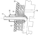
도 4는 일산화탄소 및/또는 그 외의 가스가 누출되는 것을 방지하기 위해 밀봉 링과 가요성의 보정기를 가진 물 보호 파이프를 포함하는 종래의 캐스트 스테이브 이차 지지부를 도시한 측면 횡단면도이다.
도 5는 일산화탄소 및/또는 그 외의 가스가 누출되는 것을 방지하기 위해 물 파이프에 밀봉된 가요성의 보정기를 가진 물 보호 파이프를 포함하는 종래의 드릴링되고 플러깅된 스테이브 이차 지지부를 도시한 측면 횡단면도이다.
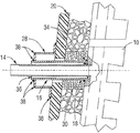
도 6은 스테이브 내에 일체로 주조되고 벌어진(flared) 단부를 가진 물 보호 파이프를 포함하는 본 발명의 기밀식 이차 스테이브 지지부의 바람직한 한 구체예를 도시한 측면 횡단면도이다.
도 7은 물 보호 파이프를 포함하고 물 보호 파이프와 스테이브 사이 및 물 파이프와 스테이브 사이에서 기밀의 기계식 연결부를 사용하는 본 발명의 이차 스테이브 지지부의 바람직한 한 구체예를 도시한 측면 횡단면도이다.
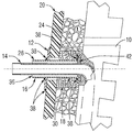
도 8은 밀봉 링과 물 파이프 사이 및 밀봉 링과 물 보호 파이프 사이에 기밀의 기계식 연결부를 포함하는 본 발명의 이차 스테이브 지지부의 바람직한 구체예를 도시한 측면 횡단면도로서, 밀봉 링을 포함하는 이러한 조립체는 스테이브 내에서 주조된다.
도 9는 밀봉 링과 물 보호 파이프 사이에 기밀의 기계식 연결부와 스테이브 내에 주조된 테이퍼구성의 밀봉 링과 물 보호 파이프를 포함하는 본 발명의 이차 스테이브 지지부의 바람직한 한 구체예를 도시한 측면 횡단면도로서, 이 역시 스테이브 내에 주조될 수 있다.In order that the present invention may be readily understood and easily practiced, the present invention will now be described by way of non-limiting example only with reference to the following drawings.
1 is a conventional cast stave including a water protection pipe with a sealing plate support that utilizes a refractory or grout material in an annular space between the water pipe and the water protection pipe to prevent leakage of carbon monoxide and / or other gases. (cast stave) A side cross-sectional view of the secondary support.
FIG. 2 shows a conventional cast stave including a water protection pipe with a sealing plate support that uses a sealing ring to seal the annular space between the water pipe and the water protection pipe to prevent leakage of carbon monoxide and / or other gases. A side cross-sectional view of the secondary support.
FIG. 3 is a side cross-sectional view of a conventional cast stave secondary support including a water protection pipe having a sealing ring and a rigid compensator to prevent leakage of carbon monoxide and / or other gases.
4 is a side cross-sectional view of a conventional cast stave secondary support including a water protection pipe with a sealing ring and a flexible compensator to prevent leakage of carbon monoxide and / or other gases.
FIG. 5 is a side cross-sectional view of a conventional drilled and plugged stave secondary support including a water protection pipe with a flexible compensator sealed to the water pipe to prevent leakage of carbon monoxide and / or other gases.
FIG. 6 is a side cross-sectional view of a preferred embodiment of the hermetic secondary stave support of the present invention including a water protection pipe having an integrally cast and flared end in the stave. FIG.
FIG. 7 is a side cross-sectional view of a preferred embodiment of the secondary stave support of the present invention that includes a water protection pipe and uses a hermetic mechanical connection between the water protection pipe and the stave and between the water pipe and the stave. FIG.
8 is a side cross-sectional view of a preferred embodiment of the secondary stave support of the present invention that includes a hermetic mechanical connection between the sealing ring and the water pipe and between the sealing ring and the water protection pipe, such an assembly comprising a sealing ring. Is cast in a stave.
FIG. 9 is a side cross-sectional view of a preferred embodiment of the secondary stave support of the present invention including a hermetic mechanical connection between the sealing ring and the water protection pipe and a tapered sealing ring and water protection pipe cast in the stave. FIG. As such, it can also be cast into a stave.
하기 상세한 설명에서, 본 발명의 일부분을 구성하며 예시적으로 도시된 도면들과 예들 및 본 발명의 주제가 실시되는 구체예들이 참조된다. 이 구체예들은 당업자가 구체예들을 잘 실시할 수 있게 하도록 충분히 상세하게 기술되며, 그 외의 다른 구체예들도 이용될 수 있고 본 발명의 주된 주제의 범위를 벗어나지 않고 구조적으로 또는 논리적으로 변형할 수 있는 사실을 이해해야 한다. 본 발명의 이러한 주된 주제는, 개별적으로 및/또는 전체적으로, 본 명세서에서, 실제로 하나 이상의 발명이 기술되었을 때 본 출원의 범위를 일군 발명 또는 진보성 문제에 자발적으로 제한하기 위한 것이 아니라 단지 편의상 용어 "발명(invention)"으로 지칭될 수 있다.In the following detailed description, reference is made to the drawings and examples, which form a part thereof, and in which embodiments of the subject matter are practiced. These embodiments are described in sufficient detail to enable those skilled in the art to practice the embodiments well, and other embodiments may be utilized and may be modified structurally or logically without departing from the scope of the subject matter of the present invention. Understand the facts This main subject matter of the present invention, individually and / or in its entirety, herein is not intended to spontaneously limit the scope of the present application to a group of inventions or inventive issues when one or more inventions are described, but merely for convenience. (invention) ".
따라서, 하기 설명은 제한적인 의미로 기술되는 것이 아니며, 본 발명의 주된 주제의 범위는 하기 청구범위 및 청구범위의 균등예(equivalent)들에 의해 정의된다.The following description, therefore, is not to be taken in a limiting sense, and the scope of the main subject matter of the present invention is defined by the following claims and the equivalents of the claims.
도 1은 링(12) 또는 밀폐 플레이트(closure plate)를 가진 보호 파이프(16)를 포함하는 캐스트 스테이브(cast stave)(10) 이차 지지부(secondary support)의 종래의 디자인을 예시한다. 스테이브 물 파이프(14)는 스테이브(10) 내에 주조된 제 1 단부(18)를 가진 동축구성의(coaxial) 벌어진(flared) 보호 파이프(16)를 가진다. 보호 파이프(16)는 밀폐 플레이트(12)에 용접되고, 상기 밀폐 플레이트(12)는 노 쉘(furnace shell) 벽(20)에 용접된다.1 illustrates a conventional design of a cast stave 10 secondary support comprising a
노 내부로부터 일산화탄소가 누출되는 것을 방지하기 위해 물 파이프(14)와 보호 파이프(16) 사이에는 내화성 또는 그라우트 재료(22)가 설치된다(installed).A fire resistant or
도 2는 스테이브 물 파이프(14)와 보호 파이프(16)의 제 2 단부(26)에 용접된 밀봉 링(24)과 밀폐 플레이트(12)를 포함하는 종래의 또 다른 캐스트 스테이브 2차 지지부를 예시한다.2 shows another conventional cast stave secondary support comprising a sealing
도 3은, 이와 유사한 종래의 디자인으로서, 밀폐 플레이트(12) 대신 견고한 보정기(28)를 포함하는 캐스트 스테이브 이차 지지부를 예시한다. 밀봉 링(24)이 스테이브 물 파이프(14)와 보호 파이프(16)의 제 2 단부(26)에 용접된다. 이러한 종래의 캐스트 스테이브 이차 지지부 디자인은 스테이브(10)와 노 쉘 벽(20) 사이와 보호 파이프(16)에 인접하게 위치된 개스킷 재료(30)를 가진 상태로 사용되거나 혹은 상기 개스킷 재료(30)가 없는 상태로 사용된다.FIG. 3 illustrates a cast stave secondary support comprising a
도 4는 물 파이프(14)에 결부되고(attached) 노 쉘 벽(20)에도 결부된 가요성의 보정기(32)를 포함하는 캐스트 스테이브 이차 지지부의 또 다른 종래의 디자인을 예시한다. 상기 종래의 디자인에서, 보호 파이프(16)는 노 쉘 벽(20)을 초과하여서는 연장되지 않는다. 물 보호 파이프(16)를 가진 상기 캐스트 스테이브 이차 지지부의 종래의 디자인은 스테이브(20)와 노 쉘 벽(20) 사이와 보호 파이프(16)에 인접하게 위치된 개스킷 재료(30)를 가진 상태로 사용되거나 혹은 상기 개스킷 재료(30)가 없는 상태로 사용된다.4 illustrates another conventional design of a cast stave secondary support comprising a
도 5는 노 내부로부터 일산화탄소 및/또는 그 외의 가스가 누출되는 것을 방지하기 위해 물 파이프(14)에 밀봉되고 노 쉘 벽(20)에 밀봉된 가요성의 보정기(32)를 포함하는 물 보호 파이프(16)를 가진 종래의 드릴링되고(drilled) 플러깅된(plugged) 스테이브 이차 지지부를 도시한다. 상기 종래의 디자인에서, 보호 파이프(16)는 노 쉘 벽(20)을 초과하여 연장되지 않는다.5 shows a water protection pipe including a
상기 각각의 종래의 디자인들에서, 물 파이프(14)는 도 1-3에 도시된 것과 같이 보호 파이프(16)에 결부되거나 또는 도 4-5에 도시된 것과 같이 노 쉘 벽(20)에 결부된다. 도 3-5이 팽창(expansion)을 위해 개스킷 재료(30)가 존재하는 것을 도시하고 있지만, 물 파이프(14)에 결부된 보정기와 개스킷 재료(30)를 조합하여 사용하는 것은 종래 기술의 일부분이다. 개선된 디자인은, 보호 파이프(16) 내에서 물 파이프(14)가 자유로이 이동하게 유지하는 스테이브(10)용 이차 지지부 및 노 가스 밀봉부(furnace gas seal)로서 보호 파이프(16)를 사용할 수 있을 것이다.In each of the above conventional designs, the
본 발명의 한 형태는 보호 파이프(16) 내에서 물 파이프(14)가 자유로이 이동하게 유지하는 물 밀봉부로서 물 파이프(14)를 사용하고 스테이브(10)용 이차 지지부 및 노 가스 밀봉부로서 보호 파이프(16)를 사용하는 것이다. 따라서, 본 발명의 스테이브 이차 지지부의 바람직한 구체예들은 각각 주철 스테이브(cast iron stave), 캐스트 구리 스테이브(cast copper stave) 또는 드릴링되고 플러깅된 스테이브 내에 일체로 구성될 수 있다(incorporated).One aspect of the present invention uses the
도 6에 도시된 것과 같이, 본 발명의 스테이브 이차 지지부의 바람직한 제 1 구체예는 제 1 단부(18)와 제 2 단부(26)를 가진 노 쉘(20)의 외부로 연장되는 보호 파이프(16)를 포함한다. 본 명세서에 기술되는 것과 같이 용접부(weld) 또는 그 외의 다른 연결부(38)가 밀폐 플레이트(12)와 보호 파이프(16) 사이에 위치되고 또한 밀폐 플레이트(12)와 노 쉘(20) 사이에 위치되는 것이 바람직하다. 대안으로, 보호 파이프(16)는 용접(welding), 브레이징(brazing), 납땜(soldeirng) 등에 의해 노 쉘(20)에 직접 결부될 수 있다. 보호 파이프(16)의 제 1 단부(18)는 벌어져 있으며(flared) 도 6에 도시된 것과 같이 스테이브(10) 내에 주조된 보호 파이프(1)와 물 파이프(14)를 사용하여 물 파이프(14)에 꼭 끼워맞춰진다(fitted over). 따라서, 노 내부로부터 일산화탄소 및/또는 그 외의 가스가 보호 파이프(16)와 물 파이프(14) 사이의 환형 공간(36) 내로 누출되는 것을 방지하기 위해 보호 파이프(16), 물 파이프(14) 및 스테이브(10) 사이에 기밀식 밀봉부(34)가 형성된다. 대안의 바람직한 구체예에서, 도 6의 스테이브 이차 지지부, 벌어진 보호 파이프(16)는 스테이브(10) 내에 주조되는 대신 스테이브(10)에 용접될 수 있다. 보호 파이프(16)는 보호 파이프(16)가 스테이브(10) 내에 주조 또는 용접되거나 혹은 그 외의 경우 연결될 때 기밀식 밀봉부 또는 연결부 형성을 촉진하거나 또는 보조하는 재료로 제조되는 것이 바람직하다. 도 6의 캐스트 스테이브 이차 지지부는 스테이브(10)와 노 쉘 벽(20) 사이와 보호 파이프(16)에 인접하게 위치된 개스킷 재료(30)를 가진 상태로 사용되거나 혹은 상기 개스킷 재료(30)가 없는 상태로 사용될 수 있다.As shown in FIG. 6, a first preferred embodiment of the stave secondary support of the present invention is a protective pipe extending out of the
도 7에 도시된 것과 같이, "드릴링되고 플러깅된" 스테이브(10)용 이차 지지부의 또 다른 바람직한 구체예는 기밀식 연결부(38)에 의해 노 쉘(20)과 보호 파이프(16)에 조여진(fastened) 견고한 보정기(28) 및 노 쉘(20)의 외부로 연장되는 보호 파이프(16)를 포함하는데, 상기 기밀식 연결부(38)는 스레딩(threading), 브레이징(brazaing), 납땜(solder), 용접부(weld) 또는 종래 기술에서 공지인 그 외의 다른 적절한 기계식 연결부를 포함할 수 있다. 대안으로, 도 6에 대해 위에서 기술한 것과 같이, 보호 파이프(16)는 용접, 브레이징, 납땜 등에 의해 노 쉘(20) 또는 밀폐 플레이트(12)에 직접 결부될 수 있다. 보호 파이프(16)의 제 1 단부(18)와 스테이브 물 파이프(14)는 각각 스레딩, 브레이징, 납땜, 또는 용접부 혹은 종래 기술에 공지인 그 외의 다른 적절한 기밀의 기계식 연결부를 포함할 수 있는 기밀식 연결부(34)에 의해 스테이브(10)에 고정된다. 보호 파이프(16)는 보호 파이프(16)가 스테이브(10) 내에 주조 또는 용접되거나 혹은 그 외의 경우 연결될 때 기밀식 밀봉부 또는 연결부 형성을 촉진하거나 또는 보조하는 재료로 제조되는 것이 바람직하다. 도 7의 스테이브 이차 지지부의 바람직한 한 구성에서, 스테이브(10) 및/또는 기밀식 연결부(34)는 노 가스(furnace gas)가 물 파이프(14)와 보호 파이프(16) 사이의 영역(36) 내로 유입되는 것을 방지한다. 도 7의 캐스트 스테이브 이차 지지부는 스테이브(10)와 노 쉘 벽(20) 사이와 보호 파이프(16)에 인접하게 위치된 개스킷 재료(30)를 가진 상태로 사용되거나 혹은 상기 개스킷 재료(30)가 없는 상태로 사용될 수 있다.As shown in FIG. 7, another preferred embodiment of the secondary support for the “drilled and plugged” stave 10 is fastened to the
도 8에 도시된 것과 같이, 본 발명의 스테이브 이차 지지부의 바람직한 추가적인 구체예는 밀폐 플레이트(12)와 노 쉘(20)의 외부로 연장되는 보호 파이프(16)를 포함한다. 스레딩, 브레이징, 납땜, 또는 용접부 혹은 종래 기술에 공지인 그 외의 다른 적절한 기계식 연결부를 포함할 수 있는 기밀식 연결부(38)가 밀폐 플레이트(12)와 보호 파이프(16) 사이에 위치되고 또한 밀폐 플레이트(12)와 노 쉘(20) 사이에 위치되는 것이 바람직하다. 도 6 및 7에 관해 위에서 기술한 것과 같이, 보호 파이프(16)를 노 쉘(20)에 고정시키기 위해 밀폐 플레이트(12) 대신 견고한 보정기(28)가 사용될 수 있거나, 혹은 보호 파이프(16)가 용접(welding), 브레이징(brazing), 납땜(soldeirng) 등에 의해 노 쉘(20)에 직접 결부될 수 있다. 도 8에 도시된 것과 같이, 보호 파이프(16)의 제 1 단부(18)는 더 작은 동심구조의(concentric) 스테이브 물 파이프(14)에 꼭 끼워맞춰진다. 납땜, 브레이징, 스레딩, 용접부 또는 종래 기술의 공지이거나 혹은 본 명세서에 기술된 것과 같은 그 외의 다른 기계식 연결부를 포함할 수 있는 기밀식 연결부(34)를 사용하여, 물 파이프(14)와 보호 파이프(16)의 제 1 단부(18)는 둘다 밀봉 링(40)에 고정된다. 일산화탄소 및/또는 노 내부로부터 나온 그 외의 다른 가스들이 물 파이프(14)와 보호 파이프(16) 사이의 환형 공간(36) 내로 누출되는 것을 추가로 방지하기 위해 스테이브(10)는 상기 연결부(34) 주위에 주조되어 스테이브(10) 내에 일체로 구성되는 것이 바람직하다. 보호 파이프(16)와 밀봉 링(40)은 보호 파이프(16) 및/또는 밀봉 링(40)이 스테이브(10) 내에 주조 또는 용접되거나 혹은 그 외의 경우 연결될 때 기밀식 밀봉부 또는 연결부 형성을 촉진하거나 또는 보조하는 재료로 제조되는 것이 바람직하다. 도 8의 캐스트 스테이브 이차 지지부는 스테이브(10)와 노 쉘 벽(20) 사이와 보호 파이프(16)에 인접하게 위치된 개스킷 재료(30)를 가진 상태로 사용되거나 혹은 상기 개스킷 재료(30)가 없는 상태로 사용될 수 있다.As shown in FIG. 8, a further preferred embodiment of the stave secondary support of the present invention includes a sealing
도 9에 도시된 것과 같이, 본 발명의 스테이브 이차 지지부의 또 다른 바람직한 구체예는 밀폐 플레이트(12)와 노 쉘(20)의 외부로 연장되는 보호 파이프(16)를 포함한다. 스레딩, 브레이징, 납땜, 또는 용접부 혹은 본 명세서에 기술되거나 종래 기술에 공지인 그 외의 다른 적절한 기계식 연결부를 포함할 수 있는 기밀식 연결부(38)가 밀폐 플레이트(12)와 보호 파이프(16) 사이에 위치되고 또한 밀폐 플레이트(12)와 노 쉘(20) 사이에 위치되는 것이 바람직하다. 도 6 및 7에 관해 위에서 기술한 것과 같이, 보호 파이프(16)를 노 쉘(20)에 고정시키기 위해 밀폐 플레이트(12) 대신 견고한 보정기(28)가 사용될 수 있거나, 혹은 보호 파이프(16)가 용접(welding), 브레이징(brazing), 납땜(soldeirng) 등에 의해 노 쉘(20)에 직접 결부될 수 있다. 도 9에 도시된 것과 같이, 보호 파이프(16)의 제 1 단부(18)는 더 작은 동심구조의(concentric) 스테이브 물 파이프(14)에 꼭 끼워맞춰진다. 테이퍼구성의 밀봉 링(42)의 작은 직경을 가진 단부와 보호 파이프(16)의 제 1 단부(18) 사이에 연결부(38)가 형성되며, 이를 통해 물 파이프(14)가 연장되는 것이 바람직하다. 일산화탄소 및/또는 노 내부로부터 나온 그 외의 다른 가스들이 물 파이프(14)와 보호 파이프(16) 사이의 환형 공간(36) 내로 누출되는 것을 추가로 방지하기 위해 물 파이프(14)의 일부분, 테이퍼구성된 밀봉 링(42) 및 보호 파이프(16)의 제 1 단부(18)를 포함하는 상기 조립체는 스테이브(10) 내에 일체로 구성되는 것이 바람직하다. 테이퍼구성된 밀봉 링(42)을 이용하는 이러한 똑같은 구성은 스테이브(10) 내에 주조되지 않더라도 사용될 수 있으며, 물 파이프(14)와 밀봉 링(42) 사이와 스테이브(10)와 밀봉 링(42) 사이에 기계식 연결부(38)가 형성될 수 있다. 보호 파이프(16)와 밀봉 링(42)은 보호 파이프(16) 및/또는 밀봉 링(42)이 스테이브(10) 내에 혹은 서로 주조 또는 용접되거나 혹은 그 외의 경우 연결될 때 기밀식 밀봉부 또는 연결부 형성을 촉진하거나 또는 보조하는 재료로 제조되는 것이 바람직하다. 도 9의 캐스트 스테이브 이차 지지부는 스테이브(10)와 노 쉘 벽(20) 사이와 보호 파이프(16)에 인접하게 위치된 개스킷 재료(30)를 가진 상태로 사용되거나 혹은 상기 개스킷 재료(30)가 없는 상태로 사용될 수 있다.As shown in FIG. 9, another preferred embodiment of the stave secondary support of the present invention includes a sealing
스테이브 이차 지지부의 구성요소들은 물 파이프(14), 보호 파이프(16), 및 밀봉 링(40 및 42)을 포함하고(이들에만 제한되지는 않음), 상기 밀봉 링(40 및 42)은 기밀 결합(gas tight bonding)을 촉진하도록 선택된 하나 또는 그 이상의 재료, 가령, 스틸 또는 스테인리스 스틸을 포함하는 것이 바람직하다. 보호 파이프(16)와 노 쉘 벽(20)에 결부된 보호 파이프(16)의 부속품(attachment)은 기밀 밀봉상태를 유지하면서도 스테이브(10)에 결부된 고정 방법과 절충되지 않고도 스테이브 팽창을 견디거나(withstand) 혹은 편향(deflect)하도록 설계된다. 따라서, 보호 파이프(16)는 사용될 수 있는 기밀식 밀봉부(34 및 38)와 스테이브(10)용 이차 지지부를 지지하기 위한 방법에 의해 쉘 벽(20)에 결부된다. 또한, 보호 파이프(16)를 쉘 벽(20)에 결부시키는 그 외의 다른 임의의 기계식 방법도 사용될 수 있으며, 이에 따라 스테이브(10)용 이차 지지부로서 기능을 수행할 수 있으며 사용될 수 있는 기밀식 밀봉부(34 및 38)의 무결성(integrity)을 유지할 수 있다.The components of the stave secondary support include (but are not limited to)
앞에서 기술한 상세한 설명에서, 본 발명의 대표적인 단일의 구체예에서 다양한 특징들이 함께 기술되었다. 이러한 기술 방법은 본 발명에서 청구하고 있는 구체예들이 각각의 청구항에서 명시적으로 인용되는 더 많은 특징을 요구하는 의도를 반영하는 것으로 해석되어서는 안 된다. 대신, 하기 청구항들과 같이, 본 발명의 주된 주제는 단일의 기술된 구체예의 모든 특징들보다 더 적다. 따라서, 하기 청구항들은 본 발명의 상세한 설명에 통합되며 각각의 청구항들은 자체적으로 개별적인 구체예로서 이해되어야 한다.In the foregoing detailed description, various features are described together in a representative single embodiment of the invention. Such technical methods should not be construed to reflect the intention that the embodiments claimed in this invention require more features that are explicitly recited in each claim. Instead, as in the following claims, the main subject matter of the invention is less than all the features of a single described embodiment. Accordingly, the following claims are incorporated into the detailed description of the invention and each claim is to be understood as a separate embodiment on its own.
Claims (30)
상기 이차 스테이브 지지부는:
- 제 1 단부와 제 2 단부를 가진 보호 파이프를 포함하며, 상기 보호 파이프는 스테이브에 가장 가까이 위치된 제 1 단부와 물 파이프 주위에 동축구성 방식으로 배열되고;
- 물 파이프의 제 3 부분과 보호 파이프의 제 1 단부 사이에 배치된 제 1 기밀식 밀봉부를 포함하며, 상기 제 1 기밀식 밀봉부는 노 쉘 벽 내부로부터 나온 가스가 보호 파이프와 물 파이프 사이의 환형 공간 내로 유입되는 것을 방지하는 노 스테이브용 이차 스테이브 지지부.Secondary stave for furnace stave comprising a water pipe having a first portion of the water pipe outside the furnace stave and a second portion of the water pipe outside the furnace shell wall In the support part,
The secondary stave support is:
A protective pipe having a first end and a second end, said protective pipe being arranged coaxially around the water pipe and the first end located closest to the stave;
A first hermetic seal disposed between the third portion of the water pipe and the first end of the protection pipe, wherein the first hermetic seal has an annulus between the protection pipe and the water pipe where gas from inside the furnace shell wall Secondary stave support for furnace stave to prevent entry into space.
노 쉘 벽의 외부에 있는 물 파이프의 제 2 부분은 어떠한 수단 또는 구성으로도 보호 파이프에 직접 또는 간접적으로 연결되지 않는 것을 특징으로 하는 노 스테이브용 이차 스테이브 지지부.The method of claim 1,
Secondary stave support for a furnace stave characterized in that the second part of the water pipe on the outside of the furnace shell wall is not directly or indirectly connected to the protective pipe by any means or configuration.
물 파이프의 제 1 부분 또는 제 2 부분 중 어느 부분도 어떠한 수단 또는 구성으로도 보호 파이프에 직접 또는 간접적으로 연결되지 않는 것을 특징으로 하는 노 스테이브용 이차 스테이브 지지부.The method of claim 1,
A secondary stave support for a furnace stave characterized in that neither part of the first part nor the second part of the water pipe is directly or indirectly connected to the protective pipe by any means or configuration.
보호 파이프와 물 파이프 사이의 환형 공간은 빈 공간이며 보호 파이프의 제 2 단부는 개방되어 있는 것을 특징으로 하는 노 스테이브용 이차 스테이브 지지부.The method of claim 1,
An annular space between the protective pipe and the water pipe is an empty space and the second end of the protective pipe is open.
보호 파이프의 제 1 단부는 외부를 향해 벌어져 있으며 물 파이프의 제 3 부분과 함께 스테이브 내에 주조되는 것을 특징으로 하는 노 스테이브용 이차 스테이브 지지부.The method of claim 1,
A secondary stave support for a furnace stave characterized in that the first end of the protective pipe is spread outwardly and is cast into the stave with a third portion of the water pipe.
제 1 기밀식 밀봉부는 스테이브 내에 배열되는 것을 특징으로 하는 노 스테이브용 이차 스테이브 지지부.The method of claim 1,
A secondary stave support for a furnace stave, wherein the first hermetic seal is arranged in the stave.
제 1 기밀식 밀봉부는 스테이브의 일부분으로서 형성되는 것을 특징으로 하는 노 스테이브용 이차 스테이브 지지부.The method of claim 1,
A secondary stave support for a furnace stave, wherein the first hermetic seal is formed as part of the stave.
제 1 기밀식 밀봉부는 스테이브의 외부에 배열되는 것을 특징으로 하는 노 스테이브용 이차 스테이브 지지부.The method of claim 1,
A secondary stave support for a furnace stave, wherein the first hermetic seal is arranged outside the stave.
제 1 기밀식 밀봉부는 납땜(soldering), 브레이징(brazing), 스레딩(threading), 또는 용접부(welding)로 구성된 군으로부터 선택되고 물 파이프의 제 3 부분과 보호 파이프의 제 1 단부 사이에 형성된 연결부를 포함하는 것을 특징으로 하는 노 스테이브용 이차 스테이브 지지부.The method of claim 1,
The first hermetic seal is selected from the group consisting of soldering, brazing, threading, or welding and has a connection formed between the third portion of the water pipe and the first end of the protective pipe. Secondary stave support for a furnace stave characterized in that it comprises.
이차 스테이브 지지부는 스테이브의 외측 부분과 보호 파이프 사이에 형성된 제 2 기밀식 밀봉부를 추가로 포함하며, 상기 제 2 기밀식 밀봉부는 보호 파이프의 제 1 단부와 제 2 단부 사이에 있는 보호 파이프 위에 배열되는 것을 특징으로 하는 노 스테이브용 이차 스테이브 지지부.The method of claim 1,
The secondary stave support further comprises a second hermetic seal formed between the outer portion of the stave and the protective pipe, wherein the second hermetic seal is placed over the protective pipe between the first and second ends of the protective pipe. Secondary stave support for a furnace stave, characterized in that arranged.
제 2 기밀식 밀봉부는 납땜, 브레이징, 스레딩, 또는 용접부로 구성된 군으로부터 선택된 연결부를 포함하는 것을 특징으로 하는 노 스테이브용 이차 스테이브 지지부.11. The method of claim 10,
Secondary seal support for a furnace stave, characterized in that the second hermetic seal comprises a connection selected from the group consisting of soldering, brazing, threading, or welding.
보호 파이프는 노 쉘 벽에 직접 연결되는 것을 특징으로 하는 노 스테이브용 이차 스테이브 지지부.The method of claim 1,
A secondary stave support for a furnace stave, wherein the protective pipe is connected directly to the furnace shell wall.
이차 스테이브 지지부는 노 쉘 벽에 연결된 밀폐 플레이트를 추가로 포함하고, 보호 파이프는 상기 밀폐 플레이트 내에 있는 구멍(opening)을 통해 연장되고 밀폐 플레이트에 연결되는 것을 특징으로 하는 노 스테이브용 이차 스테이브 지지부.The method of claim 1,
The secondary stave support further comprises a hermetic plate connected to the furnace shell wall, wherein the protective pipe extends through an opening in the hermetic plate and is connected to the hermetic plate. Support.
이차 스테이브 지지부는 노 쉘 벽에 연결된 견고한 보정기를 추가로 포함하고, 보호 파이프는 상기 견고한 보정기 내에 있는 구멍을 통해 연장되고 견고한 보정기에 연결되는 것을 특징으로 하는 노 스테이브용 이차 스테이브 지지부.The method of claim 1,
The secondary stave support further comprises a rigid compensator connected to the furnace shell wall, wherein the protective pipe extends through a hole in the rigid compensator and is connected to the rigid compensator.
물 파이프는 제 4 부분을 추가로 포함하고 물 파이프의 제 3 부분과 제 4 부분은 스테이브와 일체로 주조되는(integrally cast) 것을 특징으로 하는 노 스테이브용 이차 스테이브 지지부.The method of claim 1,
And wherein the water pipe further comprises a fourth portion and wherein the third and fourth portions of the water pipe are integrally cast with the stave.
물 파이프의 제 3 부분은 스테이브 내에 배열되고 납땜, 브레이징, 스레딩, 또는 용접부로 구성된 군으로부터 선택된 연결부에 의해 스테이브에 연결되는 것을 특징으로 하는 노 스테이브용 이차 스테이브 지지부.The method of claim 1,
And a third portion of the water pipe is arranged in the stave and connected to the stave by a connection selected from the group consisting of soldering, brazing, threading, or welding.
제 1 기밀식 밀봉부는 납땜, 브레이징, 스레딩, 또는 용접부로 구성된 군으로부터 선택되고 물 파이프의 제 3 부분의 외측 부분과 보호 파이프의 제 1 단부의 내측 부분 사이에 형성된 연결부를 포함하는 것을 특징으로 하는 노 스테이브용 이차 스테이브 지지부.17. The method of claim 16,
The first hermetic seal comprises a connection selected from the group consisting of soldering, brazing, threading, or welding and formed between an outer portion of the third portion of the water pipe and an inner portion of the first end of the protective pipe. Secondary stave support for furnace stave.
이차 스테이브 지지부는 스테이브의 외측 부분과 보호 파이프의 제 1 단부의 외측 표면 사이에 형성된 제 2 기밀식 밀봉부를 추가로 포함하는 것을 특징으로 하는 노 스테이브용 이차 스테이브 지지부.The method of claim 17,
The secondary stave support further comprises a second hermetic seal formed between the outer portion of the stave and the outer surface of the first end of the protective pipe.
이차 스테이브 지지부는 노 쉘 벽에 연결된 견고한 보정기를 추가로 포함하고, 보호 파이프의 제 2 단부는 견고한 보정기 내에 있는 구멍을 통해 연장되며 견고한 보정기에 연결되는 것을 특징으로 하는 노 스테이브용 이차 스테이브 지지부.The method of claim 18,
The secondary stave support further comprises a rigid compensator connected to the furnace shell wall, and the second end of the protective pipe extends through a hole in the rigid compensator and is connected to the rigid compensator. Support.
제 1 기밀식 밀봉부는 물 파이프의 제 3 부분과 보호 파이프의 제 1 단부에 연결된 밀봉 링을 포함하는 것을 특징으로 하는 노 스테이브용 이차 스테이브 지지부.The method of claim 1,
And the first hermetic seal comprises a sealing ring connected to the third portion of the water pipe and the first end of the protective pipe.
물 파이프의 제 3 부분과 보호 파이프의 제 1 단부에 연결된 밀봉 링을 포함하는 제 1 기밀식 밀봉부는 스테이브 내에 주조되는 것을 특징으로 하는 노 스테이브용 이차 스테이브 지지부.21. The method of claim 20,
And a first hermetic seal comprising a sealing ring connected to the third portion of the water pipe and the first end of the protective pipe, wherein the secondary stave support for the furnace stave is cast.
밀봉 링은 큰 수치를 가진 단부로부터 작은 수치를 가진 단부로 테이퍼구성되는 것을 특징으로 하는 노 스테이브용 이차 스테이브 지지부.21. The method of claim 20,
The secondary stave support for a furnace stave characterized in that the sealing ring is tapered from the end having the larger value to the end having the smaller value.
밀봉 링의 일부분 이상은 스테이브 내에 주조되는 것을 특징으로 하는 노 스테이브용 이차 스테이브 지지부.23. The method of claim 22,
And at least a portion of the sealing ring is cast into the stave.
적어도, 밀봉 링의 큰 수치를 가진 단부가 스테이브 내에 주조되는 것을 특징으로 하는 노 스테이브용 이차 스테이브 지지부.23. The method of claim 22,
At least a secondary stave support for a furnace stave characterized in that an end with a large value of the sealing ring is cast into the stave.
밀봉 링의 큰 수치를 가진 단부는 스테이브 내에 주조되고 밀봉 링의 작은 수치를 가진 단부는 스테이브로부터 돌출되는 것을 특징으로 하는 노 스테이브용 이차 스테이브 지지부.23. The method of claim 22,
A secondary stave support for a furnace stave characterized in that the large valued end of the sealing ring is cast into the stave and the small valued end of the sealing ring protrudes from the stave.
이차 스테이브 지지부는 밀봉 링의 작은 수치를 가진 단부와 보호 파이프의 제 1 단부의 외측 표면 사이에 제 2 기밀식 밀봉부를 추가로 포함하는 것을 특징으로 하는 노 스테이브용 이차 스테이브 지지부.The method of claim 25,
Secondary stave support further comprises a second hermetic seal between the end having the small value of the sealing ring and the outer surface of the first end of the protective pipe.
제 1 기밀식 밀봉부는 스테이브의 외부에 배열되는 것을 특징으로 하는 노 스테이브용 이차 스테이브 지지부.21. The method of claim 20,
A secondary stave support for a furnace stave, wherein the first hermetic seal is arranged outside the stave.
상기 방법은:
- 금속 보호 파이프의 제 1 단부를 스테이브의 근위부분에 위치된 동축구성의 내부 물 파이프에 기밀방식으로 결부시키는 단계; 및
- 보호 파이프의 제 2 단부를 노 쉘 벽에 기밀방식으로 결부시켜 제 2 단부가 노 쉘 벽의 외부에 있는 물 파이프 부분과 물리적으로 소통되지 않는 상태에 있도록 하는 단계를 포함하는 노 스테이브용 이차 스테이브 지지부를 제공하기 위한 방법.A method for providing a secondary stave support for a furnace stave comprising a water pipe having a portion external to the furnace shell wall, the method comprising:
The method comprising:
Sealingly connecting the first end of the metal protective pipe to the coaxial inner water pipe located proximal to the stave; And
-Secondaryly connecting the second end of the protective pipe to the furnace shell wall such that the second end is in physical communication with the portion of the water pipe outside of the furnace shell wall. Method for providing stave support.
제 1 단부를 결부시키는 방법은 용접, 브레이징, 스레딩 또는 캐스팅으로부터 선택되는 것을 특징으로 하는 노 스테이브용 이차 스테이브 지지부를 제공하기 위한 방법.29. The method of claim 28,
The method of associating the first end is selected from welding, brazing, threading, or casting.
제 2 단부를 결부시키는 방법은 용접, 브레이징, 스레딩 또는 캐스팅으로부터 선택되는 것을 특징으로 하는 노 스테이브용 이차 스테이브 지지부를 제공하기 위한 방법.29. The method of claim 28,
The method of associating the second end is selected from welding, brazing, threading or casting.
Applications Claiming Priority (3)
| Application Number | Priority Date | Filing Date | Title |
|---|---|---|---|
| US31897710P | 2010-03-30 | 2010-03-30 | |
| US61/318,977 | 2010-03-30 | ||
| PCT/US2011/030591 WO2011123568A1 (en) | 2010-03-30 | 2011-03-30 | Apparatus and method for gas tight secondary stave support |
Publications (1)
| Publication Number | Publication Date |
|---|---|
| KR20130065648A true KR20130065648A (en) | 2013-06-19 |
Family
ID=44147531
Family Applications (1)
| Application Number | Title | Priority Date | Filing Date |
|---|---|---|---|
| KR1020127028367A KR20130065648A (en) | 2010-03-30 | 2011-03-30 | Apparatus and method for gas tight secondary stave support |
Country Status (12)
| Country | Link |
|---|---|
| US (1) | US20130203007A1 (en) |
| EP (1) | EP2553372A1 (en) |
| JP (1) | JP2013524013A (en) |
| KR (1) | KR20130065648A (en) |
| CN (1) | CN103069242B (en) |
| AU (2) | AU2011235208A1 (en) |
| BR (1) | BR112012025025A2 (en) |
| CA (1) | CA2795131C (en) |
| CL (1) | CL2012002754A1 (en) |
| MX (1) | MX339045B (en) |
| WO (1) | WO2011123568A1 (en) |
| ZA (1) | ZA201208139B (en) |
Cited By (1)
| Publication number | Priority date | Publication date | Assignee | Title |
|---|---|---|---|---|
| KR20170034738A (en) | 2015-09-21 | 2017-03-29 | 유병현 | composition for tile joint of tile gap, and method of constraction for the same |
Families Citing this family (9)
| Publication number | Priority date | Publication date | Assignee | Title |
|---|---|---|---|---|
| US10954574B2 (en) | 2010-03-30 | 2021-03-23 | Macrae Technologies, Inc. | Water pipe collection box and stave cooler support |
| JP6539860B2 (en) * | 2015-04-01 | 2019-07-10 | 日鉄日新製鋼株式会社 | Stab cooler |
| CN105588880B (en) * | 2015-12-11 | 2018-10-26 | 武汉钢铁重工集团有限公司 | It blast furnace cast copper cooling wall ontology and is cast between cooling water pipe and fuses effect detection method |
| CN108692573A (en) * | 2018-07-18 | 2018-10-23 | 锦州天晟重工有限公司 | Industrial silicon and the big set of ferrosilicon furnace Special water cooling |
| CN109161622A (en) * | 2018-09-29 | 2019-01-08 | 济南荣庆节能技术有限公司 | A kind of blast furnace cooling stave and its manufacturing method |
| JP7401761B2 (en) | 2020-02-28 | 2023-12-20 | 日本製鉄株式会社 | Copper or copper alloy stave |
| TWI779501B (en) * | 2021-02-24 | 2022-10-01 | 中國鋼鐵股份有限公司 | Guiding device, guiding system and operation method thereof |
| CN113046505B (en) * | 2021-03-18 | 2022-07-01 | 中冶东方工程技术有限公司 | Combined cooling equipment for blast furnace |
| CN113152276B (en) * | 2021-03-22 | 2023-05-12 | 崔冰 | Passive anti-cracking reinforced prefabricated bridge deck connecting structure and design method thereof |
Family Cites Families (12)
| Publication number | Priority date | Publication date | Assignee | Title |
|---|---|---|---|---|
| JPS508002B1 (en) * | 1970-12-30 | 1975-04-01 | ||
| JPS508002A (en) | 1973-05-28 | 1975-01-28 | ||
| AT357576B (en) * | 1976-12-10 | 1980-07-25 | Voest Ag | COOLING PLATE FOR METALLURGICAL OVENS AND THEIR INSTALLATION WITH A FIRE-RESISTANT LINING |
| FR2458591A1 (en) * | 1979-06-06 | 1981-01-02 | Technilor | GAS SEALING ON INTERIOR COOLING PLATES AND ON EXTERIOR WALL OF HIGH-FURNACE SHIELDS |
| FR2493871A1 (en) * | 1980-11-07 | 1982-05-14 | Usinor | COOLING PLATES FOR BLAST FURNACES |
| DE3100321C1 (en) * | 1981-01-08 | 1982-09-30 | M.A.N. Maschinenfabrik Augsburg-Nürnberg AG, 4200 Oberhausen | Fastening plate coolers in metallurgical ovens, especially blast furnaces |
| JPS63190109A (en) * | 1987-01-31 | 1988-08-05 | Nippon Steel Corp | Method for removal working of stave in blast furnace |
| JP3034179B2 (en) * | 1995-02-21 | 2000-04-17 | 川崎製鉄株式会社 | Stove cooler for blast furnace |
| JP4334119B2 (en) | 2000-08-11 | 2009-09-30 | 新日鉄エンジニアリング株式会社 | Stave cooler cooling water pipe mounting reinforcement structure |
| DE10049707A1 (en) * | 2000-10-07 | 2002-04-11 | Sms Demag Ag | Cooling element used in blast furnaces comprises a region through which the coolant passes with an arrangement of internal coolant-conveying channels extending via a mouth region of tubular pieces into the edge region of the cooling element |
| EP1391521A1 (en) * | 2002-08-20 | 2004-02-25 | Voest-Alpine Industrieanlagenbau GmbH & Co. | Cooling plate for metallurgical furnace |
| JP4751238B2 (en) * | 2006-05-17 | 2011-08-17 | 新日本製鐵株式会社 | Stave cooler for blast furnace |
-
2011
- 2011-03-30 BR BR112012025025A patent/BR112012025025A2/en not_active IP Right Cessation
- 2011-03-30 EP EP11714885A patent/EP2553372A1/en not_active Withdrawn
- 2011-03-30 MX MX2012011389A patent/MX339045B/en active IP Right Grant
- 2011-03-30 AU AU2011235208A patent/AU2011235208A1/en not_active Abandoned
- 2011-03-30 KR KR1020127028367A patent/KR20130065648A/en not_active Application Discontinuation
- 2011-03-30 WO PCT/US2011/030591 patent/WO2011123568A1/en active Application Filing
- 2011-03-30 JP JP2013502816A patent/JP2013524013A/en active Pending
- 2011-03-30 CA CA2795131A patent/CA2795131C/en active Active
- 2011-03-30 CN CN201180025364.XA patent/CN103069242B/en active Active
- 2011-03-30 US US13/147,996 patent/US20130203007A1/en not_active Abandoned
-
2012
- 2012-10-01 CL CL2012002754A patent/CL2012002754A1/en unknown
- 2012-10-29 ZA ZA2012/08139A patent/ZA201208139B/en unknown
-
2016
- 2016-03-03 AU AU2016201408A patent/AU2016201408B2/en not_active Expired - Fee Related
Cited By (1)
| Publication number | Priority date | Publication date | Assignee | Title |
|---|---|---|---|---|
| KR20170034738A (en) | 2015-09-21 | 2017-03-29 | 유병현 | composition for tile joint of tile gap, and method of constraction for the same |
Also Published As
| Publication number | Publication date |
|---|---|
| WO2011123568A1 (en) | 2011-10-06 |
| CA2795131A1 (en) | 2011-10-06 |
| EP2553372A1 (en) | 2013-02-06 |
| CN103069242A (en) | 2013-04-24 |
| AU2011235208A1 (en) | 2012-10-25 |
| CA2795131C (en) | 2019-03-12 |
| US20130203007A1 (en) | 2013-08-08 |
| MX2012011389A (en) | 2013-02-26 |
| MX339045B (en) | 2016-05-06 |
| CN103069242B (en) | 2016-10-12 |
| BR112012025025A2 (en) | 2019-09-24 |
| AU2016201408A1 (en) | 2016-03-24 |
| JP2013524013A (en) | 2013-06-17 |
| CL2012002754A1 (en) | 2013-04-12 |
| AU2016201408B2 (en) | 2018-02-08 |
| ZA201208139B (en) | 2016-06-29 |
Similar Documents
| Publication | Publication Date | Title |
|---|---|---|
| AU2016201408B2 (en) | Apparatus and method for gas tight secondary stave support | |
| CN102015971A (en) | Burner holding device comprising a cooling system for a burner arrangement in an entrained bed gasifier | |
| JP2007308747A (en) | Stave cooler for blast furnace | |
| CN104313217B (en) | Blast furnace bottom | |
| WO2018037957A1 (en) | Furnace body protection stave | |
| US8834784B2 (en) | Thin stave cooler and support frame system | |
| RU2338949C1 (en) | Assembly sealing pipeline kead-through protective enclosures | |
| JP4029764B2 (en) | Stave cooler | |
| CN103562664B (en) | burner apparatus and burner assembly | |
| JP2023543051A (en) | Blast furnace with shaft supply of hot process gas | |
| CA2817708A1 (en) | Reinforced distributor for post-combustion lance | |
| US5020992A (en) | Shaft furnace | |
| JP2002060818A (en) | Structure for reinforcing fitting part of cooling water piping for stave cooler | |
| CN106904817B (en) | Coolant jacket and its end sealing method, glass furnace charging (feeding) equipment | |
| US20230032307A1 (en) | Installation structure for nozzle/plug seating block | |
| RU2300042C2 (en) | Device for sealing pipeline | |
| JP2007238975A (en) | Stave cooler and its installation method | |
| WO2009063573A1 (en) | Stave cooler for blast furnace | |
| JP7401762B2 (en) | Stave replacement method and stave | |
| CN208750702U (en) | A kind of novel pouring type boiler slag discharging tube | |
| CN209260127U (en) | A kind of no-welding-seam oxygen lance with conical | |
| JP5569315B2 (en) | Water cooling flange for metallurgical furnace | |
| JP2018115369A (en) | Stave cooler and method for repairing the same | |
| JPH09241719A (en) | Nose hard ware | |
| JPS63100112A (en) | Method for fitting stave in repairing furnace wall brick of blast furnace |
Legal Events
| Date | Code | Title | Description |
|---|---|---|---|
| E902 | Notification of reason for refusal | ||
| E902 | Notification of reason for refusal | ||
| E601 | Decision to refuse application |