KR20130045924A - Charging member - Google Patents
Charging member Download PDFInfo
- Publication number
- KR20130045924A KR20130045924A KR1020137006242A KR20137006242A KR20130045924A KR 20130045924 A KR20130045924 A KR 20130045924A KR 1020137006242 A KR1020137006242 A KR 1020137006242A KR 20137006242 A KR20137006242 A KR 20137006242A KR 20130045924 A KR20130045924 A KR 20130045924A
- Authority
- KR
- South Korea
- Prior art keywords
- elastic layer
- spherical
- surface layer
- particles
- charging member
- Prior art date
Links
Images


Classifications
-
- G—PHYSICS
- G03—PHOTOGRAPHY; CINEMATOGRAPHY; ANALOGOUS TECHNIQUES USING WAVES OTHER THAN OPTICAL WAVES; ELECTROGRAPHY; HOLOGRAPHY
- G03G—ELECTROGRAPHY; ELECTROPHOTOGRAPHY; MAGNETOGRAPHY
- G03G15/00—Apparatus for electrographic processes using a charge pattern
- G03G15/02—Apparatus for electrographic processes using a charge pattern for laying down a uniform charge, e.g. for sensitising; Corona discharge devices
- G03G15/0208—Apparatus for electrographic processes using a charge pattern for laying down a uniform charge, e.g. for sensitising; Corona discharge devices by contact, friction or induction, e.g. liquid charging apparatus
- G03G15/0216—Apparatus for electrographic processes using a charge pattern for laying down a uniform charge, e.g. for sensitising; Corona discharge devices by contact, friction or induction, e.g. liquid charging apparatus by bringing a charging member into contact with the member to be charged, e.g. roller, brush chargers
- G03G15/0233—Structure, details of the charging member, e.g. chemical composition, surface properties
-
- Y—GENERAL TAGGING OF NEW TECHNOLOGICAL DEVELOPMENTS; GENERAL TAGGING OF CROSS-SECTIONAL TECHNOLOGIES SPANNING OVER SEVERAL SECTIONS OF THE IPC; TECHNICAL SUBJECTS COVERED BY FORMER USPC CROSS-REFERENCE ART COLLECTIONS [XRACs] AND DIGESTS
- Y10—TECHNICAL SUBJECTS COVERED BY FORMER USPC
- Y10T—TECHNICAL SUBJECTS COVERED BY FORMER US CLASSIFICATION
- Y10T428/00—Stock material or miscellaneous articles
- Y10T428/24—Structurally defined web or sheet [e.g., overall dimension, etc.]
- Y10T428/24355—Continuous and nonuniform or irregular surface on layer or component [e.g., roofing, etc.]
- Y10T428/24372—Particulate matter
- Y10T428/24413—Metal or metal compound
-
- Y—GENERAL TAGGING OF NEW TECHNOLOGICAL DEVELOPMENTS; GENERAL TAGGING OF CROSS-SECTIONAL TECHNOLOGIES SPANNING OVER SEVERAL SECTIONS OF THE IPC; TECHNICAL SUBJECTS COVERED BY FORMER USPC CROSS-REFERENCE ART COLLECTIONS [XRACs] AND DIGESTS
- Y10—TECHNICAL SUBJECTS COVERED BY FORMER USPC
- Y10T—TECHNICAL SUBJECTS COVERED BY FORMER US CLASSIFICATION
- Y10T428/00—Stock material or miscellaneous articles
- Y10T428/24—Structurally defined web or sheet [e.g., overall dimension, etc.]
- Y10T428/24355—Continuous and nonuniform or irregular surface on layer or component [e.g., roofing, etc.]
- Y10T428/24372—Particulate matter
- Y10T428/24421—Silicon containing
Landscapes
- Physics & Mathematics (AREA)
- Engineering & Computer Science (AREA)
- Plasma & Fusion (AREA)
- General Physics & Mathematics (AREA)
- Electrostatic Charge, Transfer And Separation In Electrography (AREA)
Abstract
본 발명에 따르면 장기에 걸친 사용에 의해도 대전 성능이 변화되기 어려운 대전 부재가 제공된다. 상기 대전 부재는, 도전성 지지체, 탄성층 및 표면층을 갖고 있다. 상기 탄성층은, 구형 입자를, 그 적어도 일부가 상기 탄성층의 표면으로부터 노출되도록 함유하고, 그로 인해, 상기 탄성층의 표면은 조면화되어 이루어지며, 상기 구형 입자는 구형 실리카 입자, 구형 알루미나 입자 및 구형 지르코니아 입자를 포함하여 이루어지는 군으로부터 선택되는 적어도 하나로, 상기 탄성층의 표면은 상기 표면층에 의해, 상기 탄성층의 표면 형상이 상기 대전 부재의 표면 형상에 반영되도록 피복되고 있으며, 상기 표면층은, 특정한 구성 단위를 갖는 고분자 화합물을 포함한다.According to the present invention, there is provided a charging member in which charging performance is hard to change even with long-term use. The charging member has a conductive support, an elastic layer and a surface layer. The elastic layer contains spherical particles such that at least a portion thereof is exposed from the surface of the elastic layer, whereby the surface of the elastic layer is roughened, and the spherical particles are spherical silica particles, spherical alumina particles. And at least one selected from the group consisting of spherical zirconia particles, the surface of the elastic layer is covered by the surface layer so that the surface shape of the elastic layer is reflected on the surface shape of the charging member, and the surface layer is It includes a high molecular compound having a specific structural unit.
Description
본 발명은 대전 부재에 관한 것이다.The present invention relates to a charging member.
전자 사진 장치에서, 드럼 형상의 감광체의 표면에 접촉 배치된 롤러 형상의 대전 부재에 전압을 인가하고, 닙 근방에서 미소한 방전을 발생시켜서 감광체의 표면을 대전시키는 접촉 대전 방식이 알려져 있다.BACKGROUND ART In the electrophotographic apparatus, a contact charging method is known in which a voltage is applied to a roller-shaped charging member disposed in contact with a surface of a drum-shaped photosensitive member, and a small discharge is generated in the vicinity of the nip to charge the surface of the photosensitive member.
접촉 대전 방식에 사용되는 대전 부재로서는, 특허문헌 1에 기재되어 있는 바와 같이, 표면에의 현상제의 부착 등을 경감하고, 또한, 방전을 안정화시키기 위하여 표면층 중에 입자를 함유시켜, 표면을 조면화하는 일이 일반적으로 행해지고 있다.As the charging member used in the contact charging method, as described in Patent Literature 1, in order to reduce the adhesion of the developer to the surface and to stabilize the discharge, the particles are contained in the surface layer to roughen the surface. What you do is generally done.
한편, 특허문헌 2는 도전성 탄성체층 상에 옥시알킬렌기를 갖는 폴리실록산을 함유하는 높은 전기 저항을 갖는 얇은 표면층을 설치함으로써, 대전 능력을 높인 대전 부재를 개시하고 있다.On the other hand, Patent Literature 2 discloses a charging member having improved charging ability by providing a thin surface layer having a high electrical resistance containing a polysiloxane having an oxyalkylene group on the conductive elastic layer.
상기 특허문헌 1에 기재되어 있는 바와 같이, 표면층에 미립자를 함유시킴으로써 그 표면을 조면화한 대전 부재는, 감광체와의 반복 접촉에 의해, 표면층이 서서히 마모되어 간다. 그에 수반하여, 미립자가 표면층으로부터 탈락해 가서, 대전 부재의 표면층의 형상이 변화되는 경우가 있다. 그 결과, 대전 부재의 대전 성능이 경시적으로 변화되어 버리는 일이 있다.As described in the patent document 1, the surface member is gradually worn out by the repetitive contact with the photosensitive member of the charging member in which the surface is roughened by containing the fine particles in the surface layer. In connection with this, a microparticle may fall out from a surface layer, and the shape of the surface layer of a charging member may change. As a result, the charging performance of the charging member may change over time.
따라서, 본 발명의 목적은, 장기에 걸친 사용에 의해서도 대전 성능이 변화되기 어려운 대전 부재를 제공하는 데 있다.Accordingly, an object of the present invention is to provide a charging member in which charging performance is less likely to change even after long-term use.
또한, 본 발명의 목적은, 고품위 전자 사진 화상을 안정되게 형성할 수 있는 전자 사진 장치를 제공하는 데 있다.It is also an object of the present invention to provide an electrophotographic apparatus capable of stably forming a high quality electrophotographic image.
본 발명에 따르면, 도전성 지지체, 탄성층 및 표면층을 갖고, 탄성층은, 구형 입자를, 구형 입자의 적어도 일부가 탄성층의 표면으로부터 노출되도록 함유하여, 탄성층의 표면이 조면화되고, 구형 입자는 구형 실리카 입자, 구형 알루미나 입자 및 구형 지르코니아 입자를 포함하여 이루어지는 군으로부터 선택되는 하나 이상이며, 탄성층의 표면은, 표면층에 의해, 탄성층의 표면 형상이 대전 부재의 표면 형상에 반영되도록 피복되고, 표면층은, 하기 식 (1)에 나타나는 구성 단위를 갖는 고분자 화합물을 포함하는 대전 부재가 제공된다.According to the present invention, it has a conductive support, an elastic layer and a surface layer, and the elastic layer contains spherical particles so that at least a part of the spherical particles are exposed from the surface of the elastic layer, the surface of the elastic layer is roughened, and the spherical particles Is at least one selected from the group consisting of spherical silica particles, spherical alumina particles and spherical zirconia particles, and the surface of the elastic layer is covered by the surface layer so that the surface shape of the elastic layer is reflected on the surface shape of the charging member. The charging layer containing the high molecular compound which has a structural unit represented by following formula (1) as a surface layer is provided.

식 (1) 중, R1, R2는 각각 독립하여 하기 식 (2) 내지 (5) 중 어느 것을 나타낸다.In formula (1), R <1> , R <2> respectively independently represents either of following formula (2)-(5).


식 (2) 내지 (5) 중, R3 내지 R7, R10 내지 R14, R19, R20, R24 및 R25는 각각 독립하여 수소, 탄소수 1 내지 4의 알킬기, 수산기, 카르복실기 또는 아미노기를 나타낸다. R8, R9, R15 내지 R18, R22, R23, R27 내지 R30는 각각 독립하여 수소, 탄소수 1 내지 4의 알킬기를 나타낸다. n, m, l, q, s 및 t는 각각 독립하여 1 내지 8의 정수, p 및 r은 각각 독립하여 4 내지 12의 정수, x 및 y는 각각 독립하여 0 또는 1을 나타낸다. *은 식 (1) 중의 규소 원자와의 결합 위치를 나타내고, **은 식 (1) 중의 산소 원자와의 결합 위치를 나타낸다.In formulas (2) to (5), R 3 to R 7 , R 10 to R 14 , R 19 , R 20 , R 24, and R 25 are each independently hydrogen, an alkyl group having 1 to 4 carbon atoms, a hydroxyl group, a carboxyl group, or An amino group is shown. R 8 , R 9 , R 15 to R 18 , R 22 , R 23 and R 27 to R 30 each independently represent hydrogen and an alkyl group having 1 to 4 carbon atoms. n, m, l, q, s and t are each independently an integer of 1 to 8, p and r are each independently an integer of 4 to 12, and x and y each independently represent 0 or 1. * Represents a bonding position with a silicon atom in formula (1), and ** represents a bonding position with an oxygen atom in formula (1).
또한, 본 발명에 의하면, 전자 사진 감광체와, 상기 전자 사진 감광체에 접촉 배치되어 있는 대전 부재를 갖고, 해당 대전 부재가 상기 대전 부재인 전자 사진 장치가 제공된다.Moreover, according to this invention, the electrophotographic apparatus which has an electrophotographic photosensitive member and the charging member arrange | positioned in contact with the said electrophotographic photosensitive member, and this charging member is the said charging member is provided.
본 발명에 따르면, 대전 성능이 변화되기 어려운 대전 부재를 얻을 수 있다. 또한, 본 발명에 따르면, 고품위 전자 사진 화상을 안정되게 형성할 수 있는 전자 사진 장치를 얻을 수 있다.According to the present invention, a charging member in which charging performance is hard to change can be obtained. Moreover, according to this invention, the electrophotographic apparatus which can form a high quality electrophotographic image stably can be obtained.
도 1은 본 발명의 대전 부재의 표면 상태를 도시하는 모식도이다.
도 2는 본 발명의 대전 부재의 일례를 도시하는 단면도이다.
도 3은 본 발명의 대전 부재를 적용한 전자 사진 장치의 일례를 나타내는 개략 구성도이다.BRIEF DESCRIPTION OF THE DRAWINGS It is a schematic diagram which shows the surface state of the charging member of this invention.
2 is a cross-sectional view showing an example of the charging member of the present invention.
3 is a schematic configuration diagram showing an example of an electrophotographic apparatus to which the charging member of the present invention is applied.
본 발명의 대전 부재는, 도전성 기체, 탄성층 및 표면층을 갖고 있다.The charging member of the present invention has a conductive base, an elastic layer and a surface layer.
<도전성 기체><Conductive gas>
상기 기체는, 상층에 마련되는 탄성층 및 표면층을 지지 가능한 강도와 도전성을 갖는 것이다. 기체의 재질로서는, 철, 구리, 스테인리스, 알루미늄, 또는 니켈의 금속이나, 이들의 합금 등을 사용할 수 있다. 또한, 기체의 표면에, 내찰상성 부여를 목적으로 하여, 도전성을 손상시키지 않는 범위에서, 도금 처리 등의 표면 처리를 실시해도 된다.The base has strength and conductivity capable of supporting the elastic layer and the surface layer provided on the upper layer. As the material of the base, a metal of iron, copper, stainless steel, aluminum, or nickel, an alloy thereof, or the like can be used. In addition, for the purpose of imparting scratch resistance, the surface of the substrate may be subjected to surface treatment such as plating treatment in a range that does not impair conductivity.
<탄성층><Elastic Layer>
상기 탄성층은, 대전 부재에, 감광체와 닙부를 형성할 수 있는 탄성과, 도전성을 부여하는 것이며, 베이스 중합체와 첨가제를 사용하여 형성할 수 있다. 베이스 중합체로서는, 대전 부재의 사용 온도 범위에서 고무 탄성을 갖는 것이면 된다.The elastic layer imparts elasticity capable of forming a photosensitive member and a nip portion and conductivity to the charging member, and can be formed using a base polymer and an additive. As a base polymer, what is necessary is just to have rubber elasticity in the use temperature range of a charging member.
상기 베이스 중합체의 구체예로서는 이하의 것을 들 수 있다.The following are mentioned as a specific example of the said base polymer.
천연 고무(NR), 이소프렌 고무(IR), 부타디엔 고무(BR), 스티렌-부타디엔(SBR), 부틸 고무(IIR), 에틸렌-프로필렌-디엔3원 공중합체 고무(EPDM), 에피클로로히드린 단독 중합체(CHC), 에피클로로히드린-에틸렌옥시드 공중합체(CHR), 에피클로로히드린-에틸렌옥시드-알릴글리시딜에테르3원 공중합체(CHR-AGE). 아크릴로니트릴-부타디엔 공중합체(NBR), 아크릴로니트릴-부타디엔 공중합체의 수소 첨가물(H-NBR), 클로로프렌 고무(CR), 아크릴 고무(ACM, ANM) 등. Natural rubber (NR), isoprene rubber (IR), butadiene rubber (BR), styrene-butadiene (SBR), butyl rubber (IIR), ethylene-propylene-diene terpolymer rubber (EPDM), epichlorohydrin alone Polymer (CHC), epichlorohydrin-ethyleneoxide copolymer (CHR), epichlorohydrin-ethyleneoxide-allyl glycidyl ether terpolymer (CHR-AGE). Acrylonitrile-butadiene copolymer (NBR), hydrogenated product of acrylonitrile-butadiene copolymer (H-NBR), chloroprene rubber (CR), acrylic rubber (ACM, ANM) and the like.
또한, 상기 베이스 중합체에 대하여 가교제를 배합한 열경화성 고무 재료 및, 폴리올레핀계, 폴리스티렌계, 폴리에스테르계, 폴리우레탄계, 폴리아미드계, 염화비닐계 등의 열가소성 엘라스토머도 베이스 중합체로서 사용할 수 있다.Thermosetting rubber materials in which a crosslinking agent is blended with respect to the base polymer, and thermoplastic elastomers such as polyolefins, polystyrenes, polyesters, polyurethanes, polyamides, and vinyl chlorides can also be used as the base polymer.
본 발명에 따른 탄성층은, 구형 실리카 입자, 구형 알루미나 입자 및 구형 지르코니아 입자를 포함하여 이루어지는 군으로부터 선택되는 적어도 1종의 구형 입자를, 해당 구형 입자의 적어도 일부분이, 상기 탄성층으로부터 노출되도록 함유하고 있다. 해당 탄성층은, 구형 입자의 적어도 일부분이 노출됨으로써, 그 표면이 조면화되어 있다.The elastic layer according to the present invention contains at least one spherical particle selected from the group consisting of spherical silica particles, spherical alumina particles and spherical zirconia particles so that at least a part of the spherical particles is exposed from the elastic layer. Doing. The surface of the elastic layer is roughened by exposing at least a part of the spherical particles.
구형 실리카 입자, 구형 알루미나 입자 및 구형 지르코니아 입자는, 모두 높은 경도를 갖고, 후술하는 탄성층의 형성 과정에서의 연마 공정에서도 구형 입자 자체는 연삭되기 어렵다. 그로 인해, 구형을 유지한 상태에서, 탄성층의 표면에 그 일부분을 노출시킬 수 있다.The spherical silica particles, the spherical alumina particles and the spherical zirconia particles all have high hardness, and the spherical particles themselves are hardly ground even in the polishing step in the formation of the elastic layer described later. Therefore, the part can be exposed to the surface of an elastic layer in the state which maintained the spherical shape.
또한, 본 발명에 따른 대전 부재는, 상기 구형 입자에 의해 조면화된 탄성층의 표면이, 대전 부재의 표면 형상에 반영되도록, 후술하는 표면층에 의해 피복되어 이루어진다. 이때, 대전 부재가 닙에서 감광체에 대하여 가압되었을 때에도, 상기 표면층 자체의 강성과 맞물려 대전 부재의 표면 형상이 잘 유지되게 된다.Moreover, the charging member which concerns on this invention is coat | covered with the surface layer mentioned later so that the surface of the elastic layer roughened by the said spherical particle may be reflected to the surface shape of the charging member. At this time, even when the charging member is pressed against the photosensitive member in the nip, the surface shape of the charging member is well maintained in engagement with the rigidity of the surface layer itself.
본 발명에서의 구형 실리카 입자, 구형 알루미나 입자 및 구형 지르코니아 입자는 각각, 주성분으로서 실리카, 알루미나 또는 지르코니아를 포함하는 구형 입자이며, 그 밖의 물질을 함유하고 있어도 된다. 이들 구형 입자의 경도는 수정 모스 경도로 7 이상인 것이 바람직하다. 수정 모스 경도가 7 이상이면, 대전 부재가 감광체와 형성하는 닙부에서 구상 입자의 변형이 억제되어, 감광체와의 접촉 면적이 증대되는 것을 억제할 수 있다.The spherical silica particles, spherical alumina particles and spherical zirconia particles in the present invention are spherical particles each containing silica, alumina or zirconia as main components, and may contain other substances. It is preferable that the hardness of these spherical particle | grains is 7 or more in crystal Mohs' hardness. When the modified Mohs' hardness is 7 or more, the deformation of the spherical particles in the nip formed by the charging member and the photosensitive member can be suppressed, and the contact area with the photosensitive member can be suppressed from increasing.
이들 구상 입자의 평균 입경의 목표로서는, 2 ㎛ 이상, 80 ㎛ 이하, 특히는, 5 ㎛ 이상, 40 ㎛ 이하인 것이 바람직하다. 이 범위 내로 함으로써 대전 부재가 감광체에 가압되었을 때의, 닙에서의 접촉 표면의 증가를 억제할 수 있다. 또한, 대전 부재의 표면 형상을, 대전 부재의 표면에 토너 등이 부착되는 것을 유효하게 억제할 수 있는 표면 형상으로 하는 것이 용이해진다.As a target of the average particle diameter of these spherical particles, it is preferable that they are 2 micrometers or more and 80 micrometers or less, especially 5 micrometers or more and 40 micrometers or less. By setting it in this range, the increase of the contact surface in a nip when a charging member is pressed by the photosensitive member can be suppressed. Moreover, it becomes easy to make the surface shape of the charging member into the surface shape which can effectively suppress that toner etc. adhere to the surface of a charging member.
여기서, 구상 입자의 평균 입경은 이하의 측정 방법에 의해 구해지는 길이 평균 입경을 채용할 수 있다. 주사형 전자 현미경(니혼 덴시 가부시키가이샤 제조 JEOL LV5910)에 의한 구상 입자의 촬영 화상을, 화상 해석 소프트웨어(상품명: Image-ProPlus; 가부시키가이샤 플라네트론 제조)를 사용하여 해석한다. 해석은 사진 촬영 시의 미크론 바로부터 단위 길이당 화소 수를 캘리브레이션하고, 사진으로부터 무작위로 선택한 50개의 각 입자에 대해서, 화상 상의 화소 수로부터 정방향 직경을 측정하여, 얻어진 측정값의 산술 평균을 길이 평균 입경으로 한다.Here, the average particle diameter of spherical particle | grains can employ | adopt the length average particle diameter calculated | required by the following measuring methods. The picked-up image of the spherical particle | grains by a scanning electron microscope (JEOL LV5910 by Nippon Densh Co., Ltd.) is analyzed using image analysis software (brand name: Image-ProPlus; the product made by Planetron). The analysis is to calibrate the number of pixels per unit length from the micron bar at the time of photographing, measure the forward diameter from the number of pixels on the image for each of 50 randomly selected particles from the photograph, and average the arithmetic mean of the measured values. It is made into a particle size.
또한, 구형 입자의 구형도의 기준으로서는, 형상계수 SF1의 값이 100 이상, 160 이하인 것이 바람직하다. 형상계수 SF1은 수식 (1)로 표시되는 지수이며, 100에 가까울수록 구형에 가까운 것을 의미하고 있다. 구형 입자의 형상계수 SF1은 이하의 측정 방법에 의한 측정값을 채용할 수 있다. 주사형 전자 현미경으로 촬영한 화상 정보를 화상 해석 장치(가부시키가이샤 니레코 제조 Lusex3)에 입력하고, 무작위로 선택한 50개의 입자상에 대해서, 수식 (1)에 의해 SF1을 산출하고, 그 산출값의 산술 평균값을 구한다.In addition, it is preferable that the value of the shape coefficient SF1 is 100 or more and 160 or less as a reference of the sphericity of spherical particle. The shape coefficient SF1 is an index expressed by Equation (1), and the closer to 100, the closer to the sphere. The shape coefficient SF1 of spherical particle | grains can employ | adopt the measured value by the following measuring methods. Image information photographed with a scanning electron microscope is input to an image analysis device (Lexex, Nireko Co., Ltd.), and SF1 is calculated by Equation (1) for 50 randomly selected particles, and the calculated value Find the arithmetic mean.
SF1={(MXLNG)2/AREA}×(π/4)×(100) (1)SF1 = {(MXLNG) 2 / AREA} × (π / 4) × (100) (1)
(MXLNG은 입자의 절대 최대 길이를, AREA는 입자의 투영 면적을 나타낸다)(MXLNG represents the absolute maximum length of the particle, and AREA represents the projection area of the particle)
또한, 구형 입자의 비표면적은 JIS Z8830(2001년)에 준거하여 측정한 값으로, 10 ㎡/g 이하가 바람직하다. 구상 입자의 비표면적이 10 ㎡/g 이하이면 베이스 중합체에 배합했을 때에 탄성층의 경도가 과대해지는 것을 억제할 수 있다.In addition, the specific surface area of a spherical particle is a value measured based on JISZ8830 (2001), and 10 m <2> / g or less is preferable. When the specific surface area of a spherical particle is 10 m <2> / g or less, when it mix | blends with a base polymer, it can suppress that the hardness of an elastic layer becomes excessive.
구형 입자는, 실리카, 알루미나, 지르코니아의 단일 종류를 사용해도, 또한, 2종류 이상을 혼합하여 사용해도 된다. 구형 입자의 탄성층 중에서의 함유량의 기준은, 베이스 중합체 100 질량부에 대하여 10 질량부 이상, 100 질량부 이하인 것이 바람직하다. 구형 입자의 함유량이 10 질량부 이상이면, 탄성층의 표면의 조면화 때문에 충분한 양의 구형 입자를 탄성층의 표면으로부터 그 일부분을 노출시킬 수 있다. 또한, 100 질량부 이하로 함으로써, 탄성층이 과도하게 단단해지는 것을 억제할 수 있다.Spherical particles may use a single kind of silica, alumina or zirconia, or may mix and use two or more kinds. It is preferable that the reference | standard of content in the elastic layer of a spherical particle is 10 mass parts or more and 100 mass parts or less with respect to 100 mass parts of base polymers. If the content of the spherical particles is 10 parts by mass or more, a sufficient amount of spherical particles can be exposed from the surface of the elastic layer due to the roughening of the surface of the elastic layer. Moreover, by setting it as 100 mass parts or less, it can suppress that an elastic layer becomes hard too much.
탄성층은, 그 전기 저항을 조정하기 위하여 도전제를 함유하는 것이 바람직하다. 도전제로서는, 예를 들어 이하의 것을 사용할 수 있다. 카본 블랙, 그라파이트 등의 탄소 재료; 산화티타늄, 산화주석 등의 산화물; Cu, Ag 등의 금속; 산화물이나 금속을 입자 표면에 피복하여 도전화한 도전 입자 등의 전자 도전제, 과염소산리튬, 과염소산나트륨, 과염소산칼슘 등의 무기 이온 물질, 라우릴트리메틸암모늄클로라이드, 스테아릴트리메틸암모늄클로라이드, 옥타데실트리메틸암모늄클로라이드, 도데실트리메틸암모늄클로라이드, 헥사데실트리메틸암모늄클로라이드, 트리옥틸프로필암모늄브로마이드, 변성 지방족 디메틸에틸암모늄에토설페이트 등의 양이온성 계면 활성제. 라우릴베타인, 스테아릴베타인, 디메틸알킬라우릴베타인 등의 양성 이온 계면 활성제. 과염소산테트라에틸암모늄, 과염소산테트라부틸암모늄, 과염소산트리메틸옥타데실암모늄 등의 4급 암모늄염. 트리플루오로메탄술폰산리튬 등의 유기산 리튬염 등의 이온 도전제.It is preferable that an elastic layer contains a electrically conductive agent in order to adjust the electrical resistance. As a conductive agent, the following can be used, for example. Carbon materials such as carbon black and graphite; Oxides such as titanium oxide and tin oxide; Metals such as Cu and Ag; Electronic conductive agents such as conductive particles coated with oxides and metals on the surface of the particles and conductive, inorganic ionic materials such as lithium perchlorate, sodium perchlorate and calcium perchlorate, lauryltrimethylammonium chloride, stearyltrimethylammonium chloride, octadecyltrimethylammonium Cationic surfactants such as chloride, dodecyltrimethylammonium chloride, hexadecyltrimethylammonium chloride, trioctylpropylammonium bromide, and modified aliphatic dimethylethylammonium ethosulfate. Zwitterionic surfactants, such as lauryl betaine, stearyl betaine, and dimethylalkyl lauryl betaine. Quaternary ammonium salts, such as tetraethylammonium perchlorate, tetrabutylammonium perchlorate, and trimethyloctadecyl ammonium perchlorate. Ionic conductive agents such as organic acid lithium salts such as lithium trifluoromethanesulfonate.
이들 도전제는 1종 또는 2종 이상을 조합하여 사용할 수 있다. 이들 도전제의 탄성층 중의 함유량으로서는, 대전 부재에 원하는 도전성을 부여할 수 있으면, 특별히 한정되는 것은 아니다. 표면층을 박막화하기 위해서는 탄성층을 저전기 저항화하는 것이 바람직하고, 예를 들어 탄성층의 전기 저항이 102 Ω 이상, 108 Ω 이하, 보다 바람직하게는 103 Ω 이상, 106 Ω 이하가 되도록, 도전제의 함유량을 조정하는 것이 바람직하다.These electrically conductive agents can be used 1 type or in combination of 2 or more types. As content in the elastic layer of these electrically conductive agents, if a desired electroconductivity can be provided to a charging member, it will not be specifically limited. In order to thin the surface layer, it is preferable to reduce the electrical resistance of the elastic layer. For example, the electrical resistance of the elastic layer is 10 2 Ω or more, 10 8 Ω or less, more preferably 10 3 Ω or more, 10 6 Ω or less. It is preferable to adjust content of a electrically conductive agent so that it may be.
상기 탄성층에는, 그 밖에, 상기 물질의 기능을 저해하지 않는 범위에서, 필요에 따라 고무의 배합제로서 일반적으로 사용되고 있는 충전제, 가공 보조제, 노화 방지제, 가교 보조제, 가교 촉진제, 가교 촉진 보조제, 가교 지연제, 분산제 등을 함유시킬 수 있다.In addition to the elastic layer, fillers, processing aids, anti-aging agents, crosslinking aids, crosslinking accelerators, crosslinking accelerators, crosslinkings, etc., which are generally used as a compounding agent for rubber, are required as long as they do not impair the function of the substance. Retardants, dispersants, and the like.
상기 탄성층의 경도는, 대전 부재와 감광체를 접촉시켰을 때의 대전 부재의 변형을 억제하는 점에서, 아스카 C가 60도 이상, 85도 이하인 것이 바람직하고, 보다 바람직하게는 70도 이상, 80도 이하이다. 아스카 C 경도의 측정은, 측정 환경 25 ℃×55 % RH에서, 측정 대상의 표면에 아스카 C형 경도계(고분시 게이키 가부시키가이샤 제조)의 압침을 접속시켜, 1000 g 가중의 조건에서 측정한 측정값으로 할 수 있다.As for the hardness of the said elastic layer, since the deformation | transformation of the charging member at the time of contacting a charging member and a photosensitive member is suppressed, it is preferable that Asuka C is 60 degree | times or more and 85 degrees or less, More preferably, it is 70 degree | times or more and 80 degree | times. It is as follows. Asuka C hardness was measured under a 1000 g weighted condition by connecting a pressure gauge of an Asuka C hardness tester (manufactured by Toshiki Keiki Co., Ltd.) to the surface of the measurement object in a measurement environment of 25 ° C. × 55% RH. It can be a measured value.
상기한 바와 같이, 본 발명에 따른 탄성층은, 특정한 구형 입자를, 그 일부분이 노출되도록 함유하고 있다. 도 1에, 본 발명에 따른 대전 부재의 표면 근방의 확대 단면을 모식적으로 도시하였다. 도 1 중, 구형 입자(31)의 노출부(31a)는 탄성층으로 피복되어 있지 않고, 주사형 전자 현미경의 화상에서 탄성층(12)의 표면으로부터 돌출되어, 그에 따라, 탄성층의 표면은 조면화되어 있다. 또한, 본 발명에서, 탄성층(12)의 표면이란, 구형 입자(31)의 노출 부분(31a)의 표면도 포함하는 개념이다. 따라서, 본 발명에서, 탄성층(12)의 표면이, 후술하는 표면층(13)에 의해 피복되어 있는 상태란, 표면층(13)이 구형 입자(31)의 노출 부분(31a)을 포함하여 탄성층의 표면 전체를 피복하고 있는 상태를 의미하고 있다.As mentioned above, the elastic layer which concerns on this invention contains the specific spherical particle so that a part may be exposed. In FIG. 1, the expanded cross section of the surface vicinity of the charging member which concerns on this invention is shown typically. In FIG. 1, the exposed
이어서, 본 발명에 관한, 구형 입자의 적어도 일부분이 노출되어서 이루어지는 탄성층의 형성 방법을 설명한다.Next, the formation method of the elastic layer which exposes at least one part of spherical particle | grains which concerns on this invention is demonstrated.
우선, 탄성층을 구성하는 재료, 구체적으로는, 바인더 중합체, 구형 입자 및 필요에 따라 도전성 입자를, 밴버리 믹서나 가압식 니이더와 같은 밀폐형 혼합기나, 오픈 롤과 같은 개방형 혼합기를 사용하여 혼합하여, 탄성층 형성용 혼합물을 얻는다. 그 후, 이하의 (1) 내지 (3) 중 어느 방법에 의해 도전성 지지체 상의 탄성층을 형성할 수 있다.First, the materials constituting the elastic layer, specifically, the binder polymer, the spherical particles, and the conductive particles, if necessary, are mixed by using an airtight mixer such as a Banbury mixer or pressurized kneader or an open mixer such as an open roll. The mixture for elastic layer formation is obtained. Thereafter, the elastic layer on the conductive support can be formed by any of the following methods (1) to (3).
(1) 탄성층용 혼합물을 압출기에 의해 튜브 형상으로 압출 성형하고, 이것에 코어 금속을 삽입하는 방법.(1) A method of extruding a mixture for an elastic layer into a tube shape by an extruder and inserting a core metal into it.
(2) 탄성층용 혼합물을, 크로스헤드를 장착한 압출기에 의해, 코어 금속을 중심으로 원하는 외경이 되도록 원통형으로 공압출하는 방법.(2) A method in which the mixture for elastic layer is coextruded in a cylindrical shape so as to have a desired outer diameter centering on the core metal by an extruder equipped with a crosshead.
(3) 탄성층용 혼합물을 사출 성형기에 의해, 원하는 외경의 금형 내부에 주입하여 탄성층을 제조하는 방법.(3) A method for producing an elastic layer by injecting a mixture for the elastic layer into a mold having a desired outer diameter by an injection molding machine.
그 중에서도, 상기 (2)의 방법은 연속 생산이 용이하고, 공정수가 적어, 저비용에서의 제조에 적합하기 때문에 바람직하다.Especially, the method of said (2) is preferable because continuous production is easy, there are few processes, and it is suitable for manufacture at low cost.
이어서, 베이스 중합체의 성질에 따라, 필요한 가열 경화 처리를 행하여 도전성 지지체 상에 형성한 탄성층의 표면을 연마하고, 구상 입자의 일부분을 탄성층으로부터 노출시킨다. 탄성층의 표면을 연삭하는 방법으로서는, 지석 또는 탄성층을 형성한 탄성 롤러를 축방향으로 이동시켜 연삭하는 트래버스 방식, 탄성 롤러 길이보다 폭이 넓은 지석을 사용하여 탄성 롤러를 회전시켜서 연삭하는 플랜지컷 방식 등을 사용할 수 있다. 플랜지컷 방식은 탄성 롤러의 전체 폭을 한번에 연마할 수 있는 이점이 있고, 트래버스 방식보다 가공 시간의 단축을 도모할 수 있기 때문에, 바람직하다. 또한, 탄성층 표면은, 그 표면에 형성되는 표면층이 박막인 점에서, 표면 상태가 대전 부재의 표면에 끼치는 영향이 커서, 감광체와의 구동의 안정화, 또한 토너 오염 방지의 관점에서, 저마찰화 등의 표면 개질 처리를 행하는 것이 바람직하다. 표면 개질 방법으로서는, 자외선 조사, 전자선 조사·플라즈마 처리·코로나 방전 처리 등에 의할 수 있으며, 이들 표면 처리를 조합하여 사용해도 된다.Next, according to the properties of the base polymer, necessary heat curing treatment is performed to polish the surface of the elastic layer formed on the conductive support, and a portion of the spherical particles is exposed from the elastic layer. As a method for grinding the surface of the elastic layer, a flange cut for rotating and grinding the elastic roller using a traverse method in which the grinding wheel or the elastic roller formed with the elastic layer is moved in the axial direction and grinding, and a grinding wheel wider than the length of the elastic roller. Method can be used. The flange cut method is preferable because it has the advantage that the entire width of the elastic roller can be polished at once, and the machining time can be shorter than the traverse method. In addition, since the surface layer formed on the surface is a thin film, the surface of the elastic layer has a large influence on the surface of the charging member, so that the friction is reduced from the viewpoint of stabilization of driving with the photosensitive member and prevention of toner contamination. It is preferable to perform surface modification treatments, such as these. As a surface modification method, it can be based on ultraviolet irradiation, an electron beam irradiation, a plasma treatment, a corona discharge treatment, etc., and you may use combining these surface treatments.
<표면층><Surface layer>
상기 표면층은, 하기 식 (1)에서 나타나는 구성 단위를 갖는 고분자 화합물을 함유한다. 이러한 고분자 화합물은, 탄성층의 표면을 구성하는 구형 입자 및 바인더 중합체의 양쪽에 대하여 우수한 친화성을 나타낸다. 또한, 해당 고분자 화합물은, 치밀한 가교 구조를 갖기 때문에, 높은 강성을 나타낸다. 그로 인해, 탄성층으로부터 그 일부분을 노출시킨 구상 입자가 대전 부재의 표면으로부터의 탈락을 유효하게 억제할 수 있다. 그 결과로서, 본 발명에 따른 대전 부재는, 장기 사용에 의해서도 표면 형상이 변화되기 어렵다. 즉, 본 발명에 따른 대전 부재는, 대전 성능이 경시적으로 변화되기 어려운 것이 된다.The said surface layer contains the high molecular compound which has a structural unit represented by following formula (1). Such a high molecular compound exhibits excellent affinity for both spherical particles and binder polymers constituting the surface of the elastic layer. Moreover, since the said high molecular compound has a compact crosslinked structure, it exhibits high rigidity. Therefore, the spherical particle which exposed the one part from the elastic layer can suppress the fall off from the surface of a charging member effectively. As a result, the surface shape of the charging member according to the present invention is hard to change even by long-term use. That is, the charging member according to the present invention is difficult to change the charging performance over time.

식 (1) 중, R1, R2는 각각 독립하여, 식 (2) 내지 (5)를 나타낸다.In formula (1), R <1> , R <2> shows a formula (2)-(5) each independently.


상기 식 (2) 내지 (5) 중, R3 내지 R7, R10 내지 R14, R19, R20, R24 및 R25는 각각 독립하여 수소, 탄소수 1 내지 4의 알킬기, 수산기, 카르복실기 또는 아미노기를 나타낸다. R8, R9, R15 내지 R18, R22, R23 및 R27 내지 R30는 각각 독립하여 수소, 탄소수 1 내지 4의 알킬기를 나타낸다. n, m, l, q, s 및 t는 각각 독립하여 1 내지 8의 정수, p 및 r는 각각 독립하여 4 내지 12의 정수, x 및 y는 각각 독립하여 0 또는 1을 나타낸다. 기호 「*」은 식 (1)의 규소 원자와의 결합 위치를 나타내고, 기호 「**」은 식 (1)의 산소 원자와의 결합 위치를 나타낸다.In the formulas (2) to (5), R 3 to R 7 , R 10 to R 14 , R 19 , R 20 , R 24, and R 25 each independently represent hydrogen, an alkyl group having 1 to 4 carbon atoms, a hydroxyl group, and a carboxyl group. Or an amino group. R 8 , R 9 , R 15 to R 18 , R 22 , R 23 and R 27 to R 30 each independently represent hydrogen and an alkyl group having 1 to 4 carbon atoms. n, m, l, q, s and t are each independently an integer of 1 to 8, p and r are each independently an integer of 4 to 12, and x and y each independently represent 0 or 1. The symbol "*" represents the bonding position with the silicon atom of Formula (1), and the symbol "**" represents the bonding position with the oxygen atom of Formula (1).
상기 식 (2) 내지 (5)에서 나타내는 구조의 구체예로서는, 상기 식 (2) 내지 (5) 중의, R3 내지 R30가 수소 원자인 하기 식 (6) 내지 (9)에서 나타나는 것을 들 수 있다.Specific examples of the structure represented by the formulas (2) to (5) include those represented by the following formulas (6) to (9) in which R 3 to R 30 in the formulas (2) to (5) are hydrogen atoms. have.


식 (6) 내지 식 (9) 중, N, M, L, Q, S 및 T는 각각 독립하여 1 내지 8의 정수, x' 및 y'은 각각 독립하여 0 또는 1을 나타낸다. 기호 「*」은 상기 식 (1)의 규소 원자와의 결합 위치를 나타내고, 기호 「**」은 상기 식 (1)의 산소 원자와의 결합 위치를 나타낸다.In formulas (6) to (9), N, M, L, Q, S and T each independently represent an integer of 1 to 8, x 'and y' each independently represent 0 or 1. The symbol "*" shows the bond position with the silicon atom of said Formula (1), and the symbol "**" shows the bond position with the oxygen atom of said Formula (1).
이러한 표면층을 형성하기 위해서는, 표면층 형성용 도공액을 제조하고, 이를, 구상 입자의 노출부를 형성한 탄성층 상에 도포 시공하여 도막을 형성하며, 도막에 활성 에너지선을 조사하여 가교를 형성하는 방법에 의할 수 있다. 표면층용 도공액의 제조는 이하의 공정 (1)과 공정 (2)에 의할 수 있다.In order to form such a surface layer, the coating liquid for surface layer formation is manufactured, it is apply | coated on the elastic layer which formed the exposed part of spherical particle, and a coating film is formed, A method of forming bridge | crosslinking by irradiating an active energy ray to a coating film It can be by. Production of the coating liquid for surface layers can be based on the following process (1) and process (2).
공정 (1):Step (1):
하기 식 (10)으로 표현되는 에폭시기함유 가수분해성 실란화합물 (A)와, 필요에 따라 하기 식(11)으로 표현되는 가수분해성 실란화합물 (B)를 혼합하고, 물 (D), 알코올 (E)를 혼합하여 가열 환류에 의해 가수분해·축합을 행하는 공정;The epoxy group-containing hydrolyzable silane compound (A) represented by the following formula (10) is mixed with the hydrolyzable silane compound (B) represented by the following formula (11), if necessary, and water (D) and alcohol (E) Mixing and hydrolyzing and condensing by heating to reflux;
식 (10)Equation (10)
![]()
![]()
식 (11)Equation (11)
![]()
![]()
공정 (2):Step (2):
상기 공정 (1)에 의해 얻어진 가수분해·축합물에 광중합 개시제 (F)를 첨가하고, 필요에 따라 알코올 (E)에 의해 적당한 농도로 희석하는 공정.The process of adding a photoinitiator (F) to the hydrolysis-condensate obtained by the said process (1), and diluting to an appropriate density | concentration with alcohol (E) as needed.
공정 (1)에서 사용하는 상기 식(10)으로 표현되는 에폭시기함유 가수분해성 실란화합물 (A)에서, R32 내지 R34는 각각 독립하여 탄화수소기를 나타낸다. 탄화수소기로서는, 예를 들어 알킬기, 알케닐기, 아릴기 등을 들 수 있다. 이들 중에서도, 탄소수 1 내지 4의 직쇄상 또는 분지쇄상의 알킬기가 바람직하고, 구체적으로는, 메틸기, 에틸기, n-프로필기, i-프로필기, n-부틸기, t-부틸기를 들 수 있다. R31은, 에폭시기를 갖는 식 (12) 내지 (15) 중 어느 것을 나타낸다.In the epoxy group-containing hydrolyzable silane compound (A) represented by the formula (10) used in the step (1), R 32 to R 34 each independently represent a hydrocarbon group. As a hydrocarbon group, an alkyl group, an alkenyl group, an aryl group, etc. are mentioned, for example. Among these, a C1-C4 linear or branched alkyl group is preferable, and a methyl group, an ethyl group, n-propyl group, i-propyl group, n-butyl group, t-butyl group is mentioned specifically ,. R 31 represents any of Formulas (12) to (15) having an epoxy group.


식 (12) 내지 (15) 중, R40 내지 R42, R45 내지 R47, R52, R53, R57 및 R58는 각각 독립하여 수소, 탄소수 1 내지 4의 알킬기, 수산기, 카르복실기 또는 아미노기를 나타낸다. R43, R44, R48 내지 R51, R55, R56 및 R60 내지 R63는 각각 독립하여 수소, 탄소수 1 내지 4의 알킬기를 나타낸다. R54 및 R59은 각각 독립하여 수소, 탄소수 1 내지 4의 알콕시기 또는 탄소수 1 내지 4의 알킬기를 나타낸다. n', m', l', q', s', 및 t'은 각각 독립하여 1 내지 8의 정수, p' 및 r'은 각각 독립하여 4 내지 12의 정수를 나타낸다. 또한, *은 규소 원자와의 결합 위치를 나타낸다.In formulas (12) to (15), R 40 to R 42 , R 45 to R 47 , R 52 , R 53 , R 57 and R 58 are each independently hydrogen, an alkyl group having 1 to 4 carbon atoms, a hydroxyl group, a carboxyl group or An amino group is shown. R 43 , R 44 , R 48 to R 51 , R 55 , R 56 and R 60 to R 63 each independently represent hydrogen and an alkyl group having 1 to 4 carbon atoms. R 54 and R 59 each independently represent hydrogen, an alkoxy group having 1 to 4 carbon atoms, or an alkyl group having 1 to 4 carbon atoms. n ', m', l ', q', s ', and t' each independently represent an integer of 1 to 8, and p 'and r' each independently represent an integer of 4 to 12. In addition, * represents a bonding position with a silicon atom.
에폭시기 함유 가수분해성 실란화합물 (A)로서, 구체적으로 이하의 것을 들 수 있으며, 이들은 1종 또는 2종 이상을 조합하여 사용할 수 있다.As an epoxy group containing hydrolysable silane compound (A), the following are mentioned specifically, These can be used 1 type or in combination of 2 or more types.
4-(트리메톡시실릴)부탄-1,2-에폭시드, 5,6-에폭시헥실트리에톡시실란, 8-옥시란-2-일옥틸트리메톡시실란, 8-옥시란-2-일옥틸트리에톡시실란, 3-글리시독시프로필트리메톡시실란, 3-글리시독시프로필트리에톡시실란, 1-(2-트리에톡시실릴)메틸시클로헥산-3,4-에폭시드, 1-(2-트리에톡시실릴)에틸시클로헥산-3,4-에폭시드, 3-(3,4-에폭시시클로헥실)메틸옥시프로필트리메톡시실란.4- (trimethoxysilyl) butane-1,2-epoxide, 5,6-epoxyhexyltriethoxysilane, 8-oxirane-2-yloctyltrimethoxysilane, 8-oxirane-2-yloctyl Liethoxysilane, 3-glycidoxypropyltrimethoxysilane, 3-glycidoxypropyltriethoxysilane, 1- (2-triethoxysilyl) methylcyclohexane-3,4-epoxide, 1- ( 2-triethoxysilyl) ethylcyclohexane-3,4-epoxide, 3- (3,4-epoxycyclohexyl) methyloxypropyltrimethoxysilane.
또한, 공정 (1)에서 사용되는 식 (11)로 표현되는 가수분해성 실란화합물 (B)에서, 식(11) 중, R64는 알킬기, 또는 아릴기를 나타내고, R65 내지 R67은 각각 독립하여 탄화수소기를 나타낸다. R64의 알킬기로서는, 탄소수 1 내지 21의 직쇄상이 바람직하고, 보다 바람직하게는 탄소수 6 내지 10의 직쇄상이다. R64의 아릴기로서는, 페닐기가 바람직하다. R65 내지 R67의 탄화수소기로서는, 예를 들어 알킬기, 알케닐기, 또는 아릴기 등을 들 수 있다. 이들 중에서도, 탄소수 1 내지 4의 직쇄상 또는 분지쇄상의 알킬기가 바람직하고, 구체적으로는, 메틸기, 에틸기, n-프로필기, i-프로필기, n-부틸기, t-부틸기를 들 수 있다. 또한, R64가 페닐기를 갖는 가수분해성 실란화합물을 포함하는 경우, R64가 탄소수 6 내지 10의 직쇄상의 알킬기를 갖는 가수분해성 실란화합물과 병용하는 것이, 가수분해 축합 반응을 통하여 구조가 변화해도 용매와의 상용성이 양호한 점에서, 바람직하다.In the hydrolyzable silane compound (B) represented by formula (11) used in the step (1), in formula (11), R 64 represents an alkyl group or an aryl group, and R 65 to R 67 are each independently Hydrocarbon group is represented. As an alkyl group of R <64> , a C1-C21 linear is preferable, More preferably, it is a C6-C10 linear. As an aryl group of R 64 , a phenyl group is preferable. As a hydrocarbon group of R <65> -R <67> , an alkyl group, an alkenyl group, or an aryl group etc. are mentioned, for example. Among these, a C1-C4 linear or branched alkyl group is preferable, and a methyl group, an ethyl group, n-propyl group, i-propyl group, n-butyl group, t-butyl group is mentioned specifically ,. In addition, R 64 a case containing a hydrolyzable silane compound having a phenyl group, R 64 is not used in combination with the hydrolyzable silane compound having an alkyl group of a straight chain having 6 to 10 carbon atoms, even if the structure is changed through the hydrolysis condensation reaction It is preferable at the point that compatibility with a solvent is favorable.
가수분해성 실란화합물 (B)의 구체예로서 이하의 것을 들 수 있다.The following are mentioned as a specific example of a hydrolyzable silane compound (B).
메틸트리메톡시실란, 메틸트리에톡시실란, 에틸트리메톡시실란, 에틸트리에톡시실란, 프로필트리메톡시실란, 프로필트리에톡시실란, 헥실트리메톡시실란, 헥실트리에톡시실란, 헥실트리프로폭시실란, 데실트리메톡시실란, 데실트리에톡시실란, 페닐트리메톡시실란, 페닐트리에톡시실란, 페닐트리프로폭시실란, 옥틸트리에톡시실란.Methyltrimethoxysilane, methyltriethoxysilane, ethyltrimethoxysilane, ethyltriethoxysilane, propyltrimethoxysilane, propyltriethoxysilane, hexyltrimethoxysilane, hexyltriethoxysilane, hexyltri Propoxysilane, decyltrimethoxysilane, decyltriethoxysilane, phenyltrimethoxysilane, phenyltriethoxysilane, phenyltripropoxysilane, octyltriethoxysilane.
가수분해성 화합물 (B)로서, 상기 구체예에 기재한 화합물군으로부터 선택되는 2개 이상을 조합하여 사용해도 된다. 또한, 상기 구체예에 기재한 화합물 중의 알킬기의 적어도 1개의 수소 원자가 불소 원자로 치환된 것도 가수분해성 화합물 (B)로서 사용할 수 있다.As a hydrolysable compound (B), you may use combining two or more selected from the compound group described in the said specific example. Moreover, the thing in which at least 1 hydrogen atom of the alkyl group in the compound described in the said specific example was substituted by the fluorine atom can also be used as a hydrolysable compound (B).
상기 공정 (1)에 사용하는 물 (D)의 첨가량은, 가수분해성 실란화합물 (A) 및 (B)의 합계의 몰수 (A)+(B)에 대한 물의 몰수 (D)와의 비 ROR=(D)/((A)+(B))가 0.3 이상, 6.0 이하인 것이 바람직하다. 또한, ROR이 1.2 이상, 3.0 이하인 것이 보다 바람직하다. ROR이 0.3 이상이면, 축합 반응이 충분히 행해져, 표면층용 도공액에 미반응된 실리카 화합물이 잔존하는 것을 억제하여, 가교 밀도가 높은 막이 얻어진다. ROR이 6.0 이하이면 축합 반응의 속도가 빨라져 표면층용 도공액에 백탁이나 침전이 생성되는 것을 억제할 수 있고, 또한, 극성이 높아져서 축합물과의 상용성이 저하되는 것을 억제할 수 있다.The amount of water (D) used in the step (1) is a ratio of the number of moles (D) of water to the number of moles (A) + (B) of the sum of the hydrolyzable silane compounds (A) and (B) R OR = It is preferable that (D) / ((A) + (B)) is 0.3 or more and 6.0 or less. Moreover, it is more preferable that R OR is 1.2 or more and 3.0 or less. When R OR is 0.3 or more, the condensation reaction is sufficiently performed to prevent the unreacted silica compound from remaining in the coating liquid for the surface layer, thereby obtaining a film having a high crosslinking density. When R OR is 6.0 or less, the rate of condensation reaction is accelerated, and it can suppress that cloudiness and precipitation generate | occur | produce in the coating liquid for surface layers, and also it can suppress that polarity becomes high and compatibility with a condensate falls.
알코올 (E)은 가수분해성 실란화합물 (A), (B)의 가수분해·축합물을 상용시키기 위하여 사용된다. 알코올 (E)로서는, 제1급 알코올, 제2급 알코올, 제3급 알코올, 제1급 알코올과 제2급 알코올의 혼합계, 제1급 알코올과 제3급 알코올의 혼합계를 사용하는 것이 바람직하다. 알코올로서, 특히, 에탄올, 메탄올과 2-부탄올의 혼합 용액, 에탄올과 2-부탄올의 혼합 용액이 바람직하다.Alcohol (E) is used for making the hydrolyzable condensate of a hydrolyzable silane compound (A), (B) compatible. As the alcohol (E), it is possible to use a primary alcohol, a secondary alcohol, a tertiary alcohol, a mixed system of a primary alcohol and a secondary alcohol, and a mixed system of a primary alcohol and a tertiary alcohol. desirable. As the alcohol, in particular, a mixed solution of ethanol, methanol and 2-butanol, and a mixed solution of ethanol and 2-butanol are preferable.
상기 공정 (1)에서, 이들을 혼합하고, 가열 환류를 행하여, 가수분해·축합물을 형성한다. 상기 공정 (1)에서는, 가수분해성 실란화합물은 (A)의 1종 또는 2종 이상에, 가수분해성 실란화합물 (B)을 필요에 따라서 1종 또는 2종 이상을 조합하여 사용해도 되고, 또한, 금속 알콕시드 (C)를 사용해도 된다. 금속In the said process (1), these are mixed and heated and refluxed to form a hydrolysis-condensate. In the step (1), the hydrolyzable silane compound may be used in combination of one or two or more kinds of (A) with one or two or more kinds as necessary. You may use a metal alkoxide (C). metal
알콕시드 (C)로서는, 지르코늄, 하프늄, 탄탈, 티타늄에 그 원자가에 따른 수의 알콕시기가 결합한 것인 것이 바람직하다.As an alkoxide (C), it is preferable that zirconium, hafnium, tantalum, and titanium couple | bonded with the number of alkoxy groups according to the valence.
알콕시기로서는, 예를 들어 알킬옥시기, 알케닐옥시기, 아릴옥시기 등을 들 수 있고, 탄소 원자가 일부 산소 또는 질소로 치환된 것이어도 된다. 구체적으로는, 메톡시기, 에톡시기, n-프로폭시기, i-프로폭시기, n-부톡시기, t-부톡시기 등을 들 수 있다. 금속 알콕시드 (C)의 사용량은, 몰비에서 (C)/((A)+(B))≤5.0인 것이 표면층에 백탁이나 침전이 발생하는 것을 억제하고, 도공액의 보존성을 향상시킬 수 있는 점에서, 바람직하다. 또한, 0.5≤(C)/((A)+(B))≤3.0인 것이, 바람직하다. 금속 알콕시드 (C)는 에폭시기 함유 가수분해성 실란화합물 (A) 또는 이와 함께 혼합한 가수분해성 실란화합물 (B)에 물 (D)과 알코올 (E)을 첨가하여, 가수분해 축합물로 한 후에, 이 가수분해 축합물에 첨가하는 것이 바람직하다.As an alkoxy group, an alkyloxy group, an alkenyloxy group, an aryloxy group, etc. are mentioned, for example, The carbon atom substituted by some oxygen or nitrogen may be sufficient. Specifically, a methoxy group, an ethoxy group, n-propoxy group, i-propoxy group, n-butoxy group, t-butoxy group, etc. are mentioned. The use amount of the metal alkoxide (C) is that (C) / ((A) + (B)) ≤ 5.0 in the molar ratio can suppress the occurrence of cloudiness or precipitation in the surface layer, and can improve the shelf life of the coating solution. It is preferable at the point. Moreover, it is preferable that 0.5 <= (C) / ((A) + (B)) <= 3.0. After the metal alkoxide (C) is added to the epoxy group-containing hydrolyzable silane compound (A) or the hydrolyzable silane compound (B) mixed with it to add water (D) and alcohol (E) to form a hydrolysis condensate, It is preferable to add to this hydrolysis-condensation product.
상기 공정 (2)에서 사용하는 광중합 개시제 (F)는 실란 축합물에 가교를 형성시키기 위하여 사용한다. 광중합 개시제 (G)로서는, 루이스산 또는 브뢴스테드산의 오늄염, 양이온 중합 촉매를 사용할 수도 있다. 양이온 중합 촉매로서는, 예를 들어 보레이트염, 이미드화합물, 트리아진화합물, 아조화합물, 과산화물 등을 들 수 있다. 양이온 중합 촉매로서는, 감도, 안정성 및 반응성의 관점에서, 방향족 술포늄염이나 방향족 요오도늄염이 바람직하다. 특히 바람직한 양이온 중합 촉매로서, 비스(4-tert-부틸페닐)요오도늄염이나, 식 (16)으로 나타나는 화합물(상품명: 아데카 옵토머-SP150, 아사히 덴카 고교 가부시키가이샤 제조)을 들 수 있다.The photoinitiator (F) used at the said process (2) is used in order to form bridge | crosslinking in a silane condensate. As a photoinitiator (G), the onium salt of Lewis acid or Bronsted acid, and a cationic polymerization catalyst can also be used. As a cationic polymerization catalyst, a borate salt, an imide compound, a triazine compound, an azo compound, a peroxide, etc. are mentioned, for example. As a cationic polymerization catalyst, an aromatic sulfonium salt and an aromatic iodonium salt are preferable from a viewpoint of a sensitivity, stability, and reactivity. As a particularly preferable cation polymerization catalyst, a bis (4-tert-butylphenyl) iodonium salt or a compound represented by the formula (16) (trade name: Adeka Optomer-SP150, manufactured by Asahi Denka Kogyo KK) can be mentioned. .

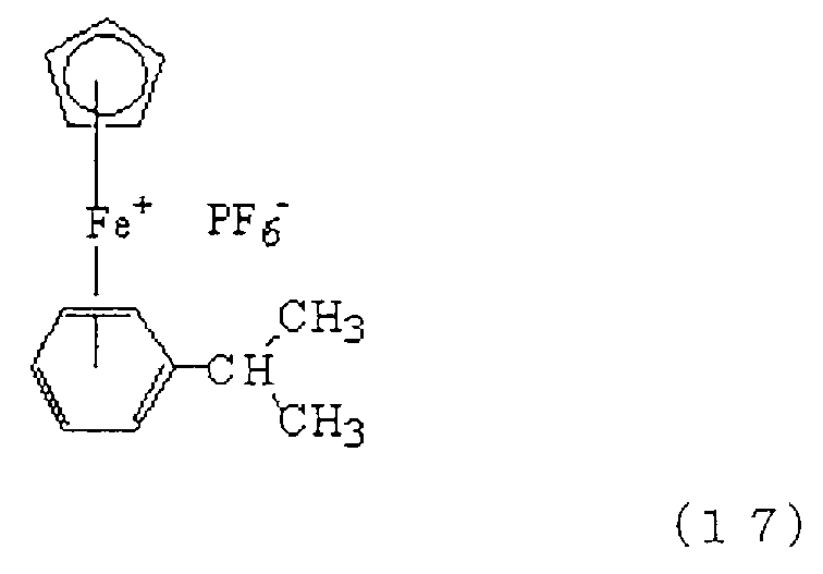
또한, 식 (17)로 나타나는 화합물(상품명: 이르가큐어(261), 치바 스페셜티 케미칼즈 가부시키가이샤 제조)도 적절하게 사용할 수 있다.Moreover, the compound (brand name: Irgacure 261 and Chiba Specialty Chemicals make) represented by Formula (17) can also be used suitably.
광중합 개시제 (G)는 표면층용 도료에의 상용성을 향상시키기 위해서, 미리 알코올이나 케톤 등의 용매, 예를 들어 메탄올이나 메틸이소부틸케톤에 용해시켜 사용하는 것이 바람직하다.In order to improve compatibility with the surface layer paint, the photopolymerization initiator (G) is preferably used after being dissolved in a solvent such as alcohol or ketone, for example, methanol or methyl isobutyl ketone.
또한, 표면층용 도료는 도포성을 향상시키기 위해서, 도포 시공에 적합한 농도로 조정하는 것이 바람직하다. 표면층용 도료가 저점도일수록 표면층의 막 두께를 얇게 할 수 있고, 표면층의 전기 용량이 커지기 때문에, 대전 부재의 표면의 전하량을 충분히 확보할 수 있고, 방전 불균일을 억제할 수 있으며, 감광체를 균일하게 대전시킬 수 있다. 그로 인해, 도포액을 적절히 용매로 희석하여 저점도화하는 것이 바람직하다. 이때에 도포액의 점도는, B형 점도계에서의 측정값으로, 2In addition, it is preferable to adjust the coating material for surface layers to the density | concentration suitable for application | coating construction, in order to improve applicability | paintability. The lower the viscosity of the surface layer paint, the thinner the film thickness of the surface layer, and the larger the capacitance of the surface layer, the more the amount of charge on the surface of the charging member can be secured, the discharge unevenness can be suppressed, and the photoconductor can be made uniform. It can be charged. Therefore, it is preferable to dilute a coating liquid with a solvent suitably and to make it low viscosity. At this time, the viscosity of the coating liquid is the measured value in the type-B viscometer, 2
㎫·s 이하인 것이 더욱 바람직하다. 사용하는 용제로서는, (1) 공정에서 사용하는 알코올과 마찬가지의 알코올을 사용할 수도 있다. 그 밖에, 아세트산에틸이나, 메틸에틸케톤, 메틸이소부틸케톤 등의 케톤을 사용해도 되고, 이들을 혼합하여 사용할 수도 있다. 이들 중, 특히, 메탄올이 바람직하다. 이렇게 제조된 표면층용 도공액의 탄성층에의 도포 시공 방법으로서는, 침지 도포, 스프레이 도포, 링 도포, 롤 코터를 사용한 도포 등의 방법을 사용할 수 있다.It is more preferable that it is MPa * s or less. As a solvent to be used, the alcohol similar to the alcohol used at (1) process can also be used. In addition, ketones, such as ethyl acetate, methyl ethyl ketone, and methyl isobutyl ketone, may be used, and these may be mixed and used. Among these, methanol is particularly preferable. As a coating method to the elastic layer of the coating liquid for surface layers manufactured in this way, methods, such as immersion coating, spray coating, ring coating, and application | coating using a roll coater, can be used.
상기 방법에 의해 형성한 탄성층 상의 도막에, 활성 에너지선을 조사하고, 광중합 개시제 (G)의 라디칼을 발생시켜, 이에 의해 에폭시기를 개열, 중합시켜서 가교를 형성할 수 있다. 사용하는 활성 에너지선으로서는, 자외선이, 저온에서 광중합 개시제 (G)의 라디칼을 발생시켜, 가교 반응을 진행시킬 수 있는 점에서, 바람직하다. 저온에서 가교 반응을 진행시킴으로써, 도막으로부터 용제가 급속하게 휘발되는 것을 억제하고, 도막에 상 분리, 주름이 발생하는 것을 억제하여, 탄성층과의 밀착 강도가 높은 표면층을 형성할 수 있다. 탄성층과의 밀착 강력이 높은 표면층은, 대전 부재가 온습도의 변화가 급격한 환경 하에서 사용되어, 온습도의 변화에 따라 탄성층의 체적이 변동해도, 주름이나 균열의 발생을 억제할 수 있다. 게다가, 가교 반응의 진행 시에 탄성층의 열 열화를 억제할 수 있기 때문에, 제조 공정에서의 탄성층의 전기적 특성의 저하를 억제할 수도 있다.An active energy ray is irradiated to the coating film on the elastic layer formed by the said method, and the radical of a photoinitiator (G) is generate | occur | produced, thereby cleaving and superposing | polymerizing an epoxy group and forming bridge | crosslinking. As an active energy ray to be used, an ultraviolet-ray is preferable at the point which can generate the radical of a photoinitiator (G) at low temperature, and can advance a crosslinking reaction. By advancing a crosslinking reaction at low temperature, it can suppress that a solvent volatilizes rapidly from a coating film, suppresses phase separation and wrinkles in a coating film, and can form the surface layer with high adhesive strength with an elastic layer. The surface layer having high adhesion strength with the elastic layer is used in an environment where the charging member changes rapidly in temperature and humidity, and even if the volume of the elastic layer changes with the change in temperature and humidity, generation of wrinkles and cracks can be suppressed. In addition, since deterioration of the elastic layer can be suppressed at the time of the crosslinking reaction, a decrease in the electrical properties of the elastic layer in the manufacturing process can also be suppressed.
자외선의 공급원으로서는, 고압 수은 램프, 메탈 할라이드 램프, 저압 수은 램프, 엑시머 UV 램프 등을 사용할 수 있고, 이들 중, 150 ㎚ 이상 480 ㎚ 이하의 파장의 자외선을 방사하는 것이 바람직하다. 자외선은, 조사 시간, 램프 출력, 램프와 표면층 간의 거리에 따라, 공급량을 조정하여 조사할 수 있고, 또한, 조사 시간 내에서 자외선의 조사량에 구배를 만들 수도 있다. 자외선의 적산 광량은, 8000 mJ/㎠ 정도가 바람직하다. 자외선의 적산 광량은 이하의 식으로부터 구할 수 있다.As a source of ultraviolet rays, a high pressure mercury lamp, a metal halide lamp, a low pressure mercury lamp, an excimer UV lamp, etc. can be used, and among these, it is preferable to radiate ultraviolet rays with a wavelength of 150 nm or more and 480 nm or less. Ultraviolet rays can be irradiated by adjusting the supply amount according to the irradiation time, the lamp output, and the distance between the lamp and the surface layer, and can also make a gradient in the irradiation amount of ultraviolet rays within the irradiation time. As for accumulated light quantity of an ultraviolet-ray, about 8000 mJ / cm <2> is preferable. The accumulated light amount of ultraviolet rays can be obtained from the following equation.
자외선 적산 광량 [mJ/㎠]=자외선 강도 [mW/㎠]×조사 시간 [s]UV accumulated light quantity [mJ / cm 2] = ultraviolet intensity [mW / cm 2] x irradiation time [s]
저압 수은 램프를 사용하는 경우, 자외선의 적산 광량은, 우시오 덴키 가부시키가이샤 제조의 자외선 적산 광량계 UIT-150-A나 UVD-S254(모두 상품명)을 사용하여 측정할 수 있다. 또한, 엑시머 UV 램프를 사용할 경우, 자외선의 적산 광량은, 우시오 덴키 가부시키가이샤 제조의 자외선 적산 광량계 UIT-150-A나 VUV-S172(모두 상품명)를 사용하여 측정할 수 있다.When using a low pressure mercury lamp, the accumulated light quantity of an ultraviolet-ray can be measured using the ultraviolet integrated light quantity meter UIT-150-A and UVD-S254 (all brand names) by Ushio Denki Corporation. In addition, when using an excimer UV lamp, the accumulated light quantity of an ultraviolet-ray can be measured using the ultraviolet integrated light quantity meter UIT-150-A and VUV-S172 (all brand names) by the Ushio Denki Corporation.
본 발명에 따른 표면층은, 구형 입자의 노출부를 포함하는 탄성층의 표면의 전체를 피복한다. 탄성층의 두께는, 구형 입자의 노출부의 높이보다 얇은 두께를 갖는다. 이에 따라, 탄성층의 표면 형상이, 표면층의 표면 형상, 즉, 대전 부재의 표면 형상에 반영되게 된다.The surface layer according to the present invention covers the entire surface of the elastic layer including the exposed portion of the spherical particles. The thickness of the elastic layer has a thickness thinner than the height of the exposed portion of the spherical particles. As a result, the surface shape of the elastic layer is reflected in the surface shape of the surface layer, that is, the surface shape of the charging member.
표면층의 두께는, 탄성층의 표면 형상이 대전 부재의 표면 형상에 반영되는 한, 특별히 한정되지 않는다. 표면층의 두께의 목표는, 10 ㎚ 이상, 1 ㎛ 이하, 특히는, 30 ㎚ 이상, 500 ㎚ 이하인 것이 바람직하다. 이 범위 내로 함으로써 사용 중에 대전 부재로부터의 구형 입자의 탈락을 유효하게 억제할 수 있다. 또한, 표면층의 변형을 억제하고, 감광체와의 접촉 면적이 증대되는 것을 억제할 수 있다. 표면층의 두께가 1 ㎛ 이하이면, 적절한 전기 용량을 갖고, 대전 부재의 경도가 과대해지는 것을 억제하며 감광체와 적절한 닙부를 형성할 수 있다. 표면층의 두께는, 전자 현미경에 의한 관찰에 의해 측정할 수 있다.The thickness of the surface layer is not particularly limited as long as the surface shape of the elastic layer is reflected in the surface shape of the charging member. It is preferable that the target of the thickness of a surface layer is 10 nm or more and 1 micrometer or less, especially 30 nm or more and 500 nm or less. By setting it in this range, the fall of the spherical particle from a charging member can be effectively suppressed during use. In addition, it is possible to suppress deformation of the surface layer and to increase the contact area with the photoconductor. If the thickness of the surface layer is 1 µm or less, it has an appropriate electric capacity, suppresses excessive hardness of the charging member, and can form an appropriate nip with the photoconductor. The thickness of the surface layer can be measured by observation with an electron microscope.
또한, 본 발명에 따른 대전 부재에 의하면, 전자 사진 감광체의 표면에의 토너 등의 고착을 유효하게 억제할 수 있어, 장기에 걸친 고품위 전자 사진 화상의 형성에 이바지하는 것이다.Further, according to the charging member according to the present invention, adhesion of toner and the like to the surface of the electrophotographic photosensitive member can be effectively suppressed, which contributes to the formation of a high quality electrophotographic image for a long time.
즉, 본 발명자들의 검토에 의하면, 상기 특허문헌 2에 관한 대전 부재를 장기간 사용했을 때에 전자 사진 화상에 결함이 발생하는 일이 있었다. 그 원인은 아직 해명 중이지만, 이하와 같은 메커니즘에 따르는 것으로 추정하였다. 즉, 특허문헌 2에 관한, 폴리실록산을 포함하는 표면층은, 치밀하고 높은 경도를 갖기 때문에, 감광체와의 닙에서, 닙 부분에 인입된 토너를 감광체 표면에 가압해 버려, 감광체 표면에 서서히 토너의 고착물이 축적되어 간다. 그리고, 감광체 표면에 부착되어 있는 토너가 클리닝 블레이드에 의해서도 클리닝할 수 없게 되어 간다. 그 결과, 전자 사진 화상에 결함이 발생하게 된다는 것이다.That is, according to the examination of the present inventors, a defect may arise in an electrophotographic image when using the charging member which concerns on the said patent document 2 for a long time. The cause is still being elucidated, but it is assumed that the following mechanism is followed. That is, since the surface layer containing polysiloxane which concerns on patent document 2 has dense and high hardness, in the nip with a photoreceptor, the toner which entered into the nip part is pressurized to the photoreceptor surface, and the toner adheres to the photoreceptor surface gradually. Water accumulates Then, the toner adhering to the photosensitive member surface cannot be cleaned even by the cleaning blade. As a result, a defect occurs in the electrophotographic image.
한편, 본 발명에 따른 대전 부재는, 구형 입자에 의해 조면화된 탄성층의 표면의 형상이 반영된 표면 형상을 갖는다. 그리고, 구형 입자로서 고경도의 것을 사용함과 함께, 표면층이 강성이 높은 폴리실록산을 포함함으로써, 대전 부재와 감광체와의 닙에서도, 대전 부재의 조면화된 표면 형상이 상실되기 어렵다. 즉, 닙에서의 대전 부재와 감광체의 접촉 면적이, 특허문헌 2에 관한 대전 부재를 사용한 경우와 비교하여 상대적으로 감소한다.On the other hand, the charging member according to the present invention has a surface shape in which the shape of the surface of the elastic layer roughened by spherical particles is reflected. In addition, the use of a high-hardness spherical particle and the high stiffness of the surface layer make it difficult to lose the roughened surface shape of the charging member even in the nip between the charging member and the photosensitive member. That is, the contact area of the charging member and the photosensitive member in a nip is relatively reduced compared with the case where the charging member which concerns on patent document 2 is used.
그로 인해, 토너가 감광체의 표면에 고착되기 어려워져, 감광체의 표면의 클리닝성의 경시적인 저하가 억제된다. 그 결과로서, 많은 매수의 전자 사진 화상을 형성한 경우에도, 감광체의 표면의 고착물에 기인하는 화상의 결함의 발생을 억제할 수 있다.Therefore, it is difficult for the toner to adhere to the surface of the photoconductor, and the deterioration of the cleaning property of the surface of the photoconductor over time is suppressed. As a result, even when a large number of electrophotographic images are formed, occurrence of a defect in the image due to a fixed matter on the surface of the photoconductor can be suppressed.
표면층의 체적 저항값은 108 Ω·㎝ 이상, 1015 Ω·㎝ 이하, 특히는, 1010 Ω·㎝ 이상, 1015 Ω·㎝ 이하가 바람직하다. 표면층의 체적 저항값을 상기 범위 내로 함으로써 대전 부재와 감광체 사이에서의 이상 방전의 발생을 유효하게 억제할 수 있음과 함께, 감광체의 대전을 보다 균일하게 행할 수 있다.The volume resistivity of the surface layer is preferably 10 8 Ω · cm or more, 10 15 Ω · cm or less, particularly 10 10 Ω · cm or more and 10 15 Ω · cm or less. By setting the volume resistivity value of the surface layer within the above range, occurrence of abnormal discharge between the charging member and the photosensitive member can be effectively suppressed, and the photosensitive member can be charged more uniformly.
또한, 표면층의 탄성률은, 1000 ㎫ 이상, 20000 ㎫ 이하인 것이 바람직하다. 표면층의 탄성률을 상기 범위 내로 함으로써 대전 부재와 감광체 사이에 적당한 폭의 닙을 형성할 수 있다. 또한, 구형 입자를 매몰시키는 것과 같은 변형을 억제할 수 있어, 감광체와의 접촉 면적이 과도하게 증가하는 것을 억제할 수 있다. 또한, 상기한 바와 같은 두께의 표면층이어도, 유연한 탄성층의 변형에 잘 추종할 수 있다.Moreover, it is preferable that the elasticity modulus of a surface layer is 1000 Mpa or more and 20000 Mpa or less. By carrying out the elasticity modulus of a surface layer in the said range, the nip of a suitable width can be formed between a charging member and a photosensitive member. In addition, deformation such as embedding the spherical particles can be suppressed, and an excessive increase in the contact area with the photoconductor can be suppressed. Moreover, even if it is the surface layer of thickness as mentioned above, it can follow the deformation | transformation of a flexible elastic layer well.
본 발명의 대전 부재는, 상기 기체 상에 탄성층 및 표면층을 갖는 것이면, 특별히 한정되는 것은 아니며, 기체와 탄성층 간, 탄성층과 표면층 사이에 그 밖의 층을 가져도 된다. 본 발명의 대전 부재의 일례로서, 롤러 형상의 대전 부재를 도 2의 단면도에 도시하였다. 이 대전 롤러(10)는 도전성 지지체(11) 상에 순차, 탄성층(12)과 표면층(13)을 적층한 구조를 갖는다.The charging member of the present invention is not particularly limited as long as it has an elastic layer and a surface layer on the base, and may have other layers between the base and the elastic layer and between the elastic layer and the surface layer. As an example of the charging member of the present invention, a roller-shaped charging member is shown in the cross-sectional view of FIG. The charging
<전자 사진 장치><Electrophotographic device>
본 발명의 대전 부재를 갖는 전자 사진 장치의 일례를 도 3에 도시한다. 도 3에서, 도면 부호 (21)은 원통 형상의 감광체이며, 지지체(21b) 및 지지체 상에 형성된 감광층(21a)을 갖고, 축(21c)을 중심으로 화살표 방향으로 소정의 주속도로 회전 구동된다. 회전 구동되는 감광체(21)의 표면에 가압되어, 감광체에 접촉하여 종동 회전하도록 상기 대전 롤러(10)가 배치된다. 대전 롤러(10)는 도전성 지지체(11)에 접속되는 전원(23)으로부터 마찰 전극(23a)를 통하여 공급되는 전원에 의해 소정의 직류(DC) 바이어스가 인가되고, 닙부를 형성하여 가압되는 감광체를 닙부의 근방에서 소정 전위로 대전시킨다. 계속해서, 슬릿 노광이나 레이저 빔 주사 노광 등의 노광 수단(24)으로부터 출력되는 노광을 받음으로써, 감광체의 감광층(21a)에, 원하는 화상에 대응한 정전 잠상이 형성된다. 감광층에 형성된 정전 잠상에 현상 부재(25)에 의해 토너가 공급되어 토너상이 형성된다. 감광체 상의 토너상은, 전사재 공급 수단(도시하지 않음)으로부터 감광체와 전사 수단(26) 사이의 접촉부에, 감광체의 회전과 동기하여 공급되는 종이 등의 전사재(27) 상에 순차 전사된다. 토너상이 전사된 전사재는, 감광체의 표면으로부터 분리되어 정착 수단에 도입되어서 상 정착을 받음으로써 화상 형성물(프린트, 카피)로서 장치 외에 프린트 아웃된다. 토너상 전사 후의 감광체의 표면은, 탄성체 등으로 형성되는 클리닝 블레이드를 구비한 클리닝 수단(28)에 의해 전사 나머지의 현상제(토너)가 제거되면 청정면화된다.An example of the electrophotographic apparatus which has the charging member of this invention is shown in FIG. In Fig. 3,
본 발명의 대전 부재는, 탄성층이 실리카, 알루미나, 지르코니아로 선택되는 고경도의 구상 입자를 그 일부를 노출시켜서 함유하고, 박막의 표면층을 통하여 이들 입자에 의해 표면이 조면화된다. 표면층은 구상 입자와 탄성층 양쪽과의 밀착성이 높고, 또한 탄성률이 높다. 이로 인해, 탄성층 전체면을 피복하여 구상 입자를 유지하고, 대전 부재가 감광체에 가압되었을 때 형성되는 닙에서, 구상 입자가 탄성층 표면에 노출된 상태를 유지할 수 있다. 이에 따라, 대전 부재의 표면의 요철 형상을 유지하고, 대전 부재와 감광체의 접촉 면적이 증대되는 것을 억제할 수 있다. 표면층이 박막이고, 대전 부재는 탄성층의 저경도를 유지하며, 감광체 간에 충분한 닙부를 형성할 수 있고, 접촉 불량에 의한 화상 불량이나, 대전 부재 표면에 토너나 외첨제가 부착됨으로써 발생하는 내구 화상 불량의 발생을 억제할 수 있다.The charging member of the present invention contains a portion of high-hardness spherical particles in which the elastic layer is selected from silica, alumina and zirconia, and the surface is roughened by these particles through the surface layer of the thin film. The surface layer has high adhesiveness between both the spherical particles and the elastic layer, and high elastic modulus. For this reason, the spherical particles can be maintained by covering the entire surface of the elastic layer and retaining spherical particles in the nip formed when the charging member is pressed against the photosensitive member. Thereby, the uneven | corrugated shape of the surface of a charging member can be maintained, and it can suppress that the contact area of a charging member and a photosensitive member increases. The surface layer is a thin film, and the charging member maintains the low hardness of the elastic layer and can form a sufficient nip between the photoconductors, and image defects due to poor contact, or durable image defects caused by adhesion of toner or external additives to the surface of the charging member. Can be suppressed.
실시예Example
이하에, 구체적인 실시예를 들어서 본 발명을 더욱 상세하게 설명한다. 이하에 기재하는 「부」는 「질량부」를 의미한다. 시약 등은 특히 지정이 없는 것은 시판되고 있는 고순도품을 사용하였다.Hereinafter, the present invention will be described in more detail with reference to specific examples. "Part" described below means a "mass part." Reagents and the like used commercially available high-purity products that are not specified.
[실시예 1]Example 1
[탄성층의 형성][Formation of Elastic Layer]
하기 표 1의 재료를, 6 ℓ 가압 니이더(제품명: TD6-15MDX, 가부시키가이샤 도신 제조)를 사용하여, 충전율 70 vol%, 블레이드 회전 수 30 rpm으로 16분간 혼합하여 A 반죽 고무 조성물을 얻었다.The material of Table 1 was mixed with a 6 L pressurizer (product name: TD6-15MDX, manufactured by Toshin Co., Ltd.) at a filling rate of 70 vol% and a blade rotation speed of 30 rpm for 16 minutes to obtain an A-kneading rubber composition. .
[표 1][Table 1]

계속해서, 하기 표 2의 재료를, 롤 직경 12 인치의 오픈 롤로, 전 롤 회전 수 8 rpm, 후 롤 회전 수 10 rpm, 롤 간극 2 ㎜으로, 좌우의 왕복을 합계 20회 실시하였다. 그 후, 롤 간극을 0.5㎜으로 하고 얇게 펴기 10회를 행하여, 탄성층 형성용 미가황 고무 조성물을 얻었다.Subsequently, the left and right reciprocation of the material of the following Table 2 was carried out in the open roll of 12 inches of roll diameters with the roll roll speed of 8 rpm, the roll roll speed of 10 rpm, and the roll clearance of 2 mm in total 20 times. Thereafter, the roll gap was made 0.5 mm and rolled out 10 times, and the unvulcanized rubber composition for elastic layer formation was obtained.
[표 2][Table 2]

직경 6 ㎜, 길이 252 ㎜의 원기둥형 코어 금속(강제, 표면은 니켈 도금)의 원기둥면의 축방향 중앙부 226 ㎜에 도전성 가황 접착제(메탈록 U-20; 가부시키가이샤 도요 가가쿠 겐큐쇼 제조)를 도포하고, 80 ℃에서 30분 간 건조하였다. 이어서, 상기 미가황 고무 조성물을, 크로스헤드를 사용한 압출 성형에 의해, 코어 금속을 중심으로 하여 동축형으로 원통형으로 동시에 압출하여, 코어 금속의 외주에 미가황 고무 조성물이 코팅된 직경 8.8 ㎜의 미가황 고무 롤러를 제작하였다. 압출기는, 실린더 직경 45 ㎜(Φ45), L/D=20의 압출기를 사용하고, 압출 시의 온도 조절은 헤드 90 ℃, 실린더 90 ℃, 스크류 90 ℃로 하였다. 성형한 미가황 고무 롤러의 양단을 절단하고, 탄성층 부분의 축방향 폭을 228 ㎜로 한 후, 전기로에서 160 ℃ 40분의 가열 처리를 행하여, 가황 고무 롤러를 얻었다. 얻어진 가황 고무 롤러의 표면을 플랜지컷 연삭 방식의 연마기로 연마하고, 단부 직경 8.35 ㎜, 중앙부 직경 8.50 ㎜의 크라운 형상의 탄성체층을 갖는 고무 롤러를 얻었다.Conductive vulcanizing adhesive (Metalloc U-20; manufactured by Toyo Chemical Co., Ltd.) at 226 mm of the central portion of the cylindrical surface of the cylindrical core metal (steel, the surface is nickel plated) having a diameter of 6 mm and a length of 252 mm. Was applied and dried at 80 ° C. for 30 minutes. Subsequently, the unvulcanized rubber composition was simultaneously extruded coaxially and cylindrically around the core metal by extrusion molding using a crosshead, and the uncured rubber composition having a diameter of 8.8 mm coated with the unvulcanized rubber composition on the outer circumference of the core metal. A sulfur rubber roller was produced. The extruder used the cylinder diameter 45 mm (Φ45) and the extruder of L / D = 20, and the temperature control at the time of extrusion was made into the head 90 degreeC, the cylinder 90 degreeC, and the screw 90 degreeC. Both ends of the molded unvulcanized rubber roller were cut and the axial width of the elastic layer portion was 228 mm, and then heat treatment was performed at 160 ° C. for 40 minutes in an electric furnace to obtain a vulcanized rubber roller. The surface of the obtained vulcanized rubber roller was grind | polished with the grinder of a flange cut grinding system, and the rubber roller which has a crown-shaped elastic body layer of 8.35 mm of end diameters, and 8.50 mm of center part diameters was obtained.
[표면층의 형성][Formation of surface layer]
하기 표 3에 기재된 재료를 혼합하고, 실온에서 교반한 후, 24시간 가열 환류를 행하여 유기 무기 하이브리드 졸의 축합물 졸 1을 얻었다.The materials shown in Table 3 below were mixed and stirred at room temperature, and then heated to reflux for 24 hours to obtain a condensate sol 1 of the organic inorganic hybrid sol.
[표 3][Table 3]

이 축합물 졸 1을 2-부탄올/에탄올의 혼합 용제에 첨가하여, 고형분 7 질량% 함유하는 축합물 졸 액 1을 제조하였다. 단, 고형분이란, 가수분해성 실란화합물이 전부 탈수 축합했다고 가정했을 때의 축합물이다. 이하, 고형분이란 특별한 표기가 없는 한, 마찬가지의 의미로 사용하고 있다.This condensate sol 1 was added to the mixed solvent of 2-butanol / ethanol to prepare a condensate sol liquid 1 containing 7% by mass of solid content. However, solid content is a condensate when it is assumed that all the hydrolyzable silane compounds are dehydrated and condensed. Hereinafter, solid content is used by the same meaning unless there is particular notice.
이 축합물 졸 액 1의 100 g에 대하여 광 양이온 중합 개시제로서의 방향족 술포늄염(상품명: 아데카 옵토머 SP-150, 아사히 덴카 고교 가부시키가이샤 제조)을 0.35 g의 비율로 첨가하여, 도포 원액 1을 얻었다.To 100 g of this condensate sol liquid 1, an aromatic sulfonium salt (trade name: Adeka Optomer SP-150, manufactured by Asahi Denka Kogyo Co., Ltd.) as a photocationic polymerization initiator was added at a rate of 0.35 g, and the coating stock solution 1 Got.
도포 원액 1을 고형분이 4.5 질량%가 되도록 2-부탄올/에탄올의 혼합 용제로 희석한 것을 표면층 형성용 도포액 1으로 하였다. 표면층 형성용 도포액 1의 점도를 B형 점도계(도키 산교 가부시키가이샤 제조 RE500L, 0.8°×R24 콘 로터 사용)로 측정한 바, 1 ㎫·s 이하였다. 측정 조건은 측정 온도 25 ℃, 샘플량은 0.6 ㎖로 행하였다.What diluted the coating stock solution 1 with the mixed solvent of 2-butanol / ethanol so that solid content might be 4.5 mass% was used as the coating liquid 1 for surface layer formation. It was 1 MPa * s or less when the viscosity of the coating liquid 1 for surface layer formation was measured with the Brookfield viscometer (The REKI L manufactured by Toki Sangyo Co., Ltd., 0.8 degrees X R24 cone rotor). The measurement conditions were performed at 25 degreeC of measurement temperature, and the sample quantity was 0.6 ml.
이어서, 고무 롤러의 탄성층 상에 표면층 형성용 도포액 1을 링 도포했다(도출량: 0.120 ㎖/s, 링 헤드의 이동 스피드: 85 ㎜/s, 총 배출량: 0.130㎖).Subsequently, the coating liquid 1 for surface layer formation was ring-coated on the elastic layer of a rubber roller (ejection amount: 0.120 ml / s, the moving speed of a ring head: 85 mm / s, total discharge amount: 0.130 ml).
계속해서, 저압 수은 램프(해리슨 도시바 라이팅 가부시키가이샤 제조)를 사용하여, 254 ㎚의 센서에서의 감도로, 자외선의 광량이 8000 mJ/㎠가 되도록, 표면층 형성용 도포액 1의 도막을 형성한 고무 롤러를 회전시키면서 자외선을 조사하여 상기 도막을 경화시켰다. 이렇게 해서, 탄성층의 표면이, 상기 탄성층의 표면 형상이 반영됨으로써 요철 형상의 표면 형상을 갖는 표면층으로 피복된 대전 롤러(1)를 제작하였다. 대전 롤러(1)의 대전 성능의 내구성 및 표면층의 물성을, 이하와 같이 하여 평가하고, 측정하였다.Then, using the low pressure mercury lamp (made by Harrison Toshiba Lighting Co., Ltd.), the coating film of the coating liquid 1 for surface layer formation was formed so that the light amount of ultraviolet-ray might be 8000 mJ / cm <2> by the sensitivity with a sensor of 254 nm. The coating film was cured by irradiating ultraviolet rays while rotating a rubber roller. In this way, the charging roller 1 in which the surface of the elastic layer was covered with the surface layer having an uneven surface shape by reflecting the surface shape of the elastic layer was produced. The durability of the charging performance of the charging roller 1 and the physical property of the surface layer were evaluated and measured as follows.
[화상 평가][Image evaluation]
화상 형성에 사용하는 전자 사진 장치로서, A4 크기의 종이를 세로 방향으로 출력 가능한 레이저 빔 프린터(상품명: 레이저젯 P1005, 휴렛 팩커드 사 제조)를 준비하였다. 이 레이저 빔 프린터용 프로세스 카트리지에, 상기에서 제작한 대전 롤러를 내장하고, 그 프로세스 카트리지를 상기 전자 사진 장치에 장전하였다.As an electrophotographic apparatus used for image formation, a laser beam printer (trade name: LaserJet P1005, manufactured by Hewlett-Packard Co., Ltd.) capable of outputting A4-size paper in a vertical direction was prepared. In the process cartridge for laser beam printers, the charging roller produced above was incorporated, and the process cartridge was loaded in the electrophotographic apparatus.
대전 롤러의 코어 금속에 외부 전원(모델 PM04015A: 트렉 사 제조)에 의해, -1200V의 직류 전압을 인가하고, 온도 23 ℃, 상대 습도 50 %의 환경 하에서, 솔리드 흑색 화상을 일부에 포함하는 하프톤 화상(전자 사진 감광체의 회전 방향과 수직 방향으로 폭 1 도트의 선을 간격 2 도트로 그리는 화상)을 1장 형성하였다. 계속해서, 인자 농도 1%의 전자 사진 화상을 2500장 형성하였다. 또한, 계속하여, 1장째와 같은, 솔리드 흑색 화상을 일부에 포함하는 하프톤 화상을 1장 형성하였다. 또한, 화상 형성은, 1장 인자할 때마다 감광 드럼의 회전을 완전히 정지시키는, 소위, 간헐 모드에서 행하였다.A halftone containing a solid black image in a part of the core metal of the charging roller by an external power supply (model PM04015A: manufactured by Trex) and applying a direct current voltage of -1200 V, under a temperature of 23 ° C. and a relative humidity of 50%. One image (image which draws a line of width 1 dot at intervals 2 dots in the direction perpendicular to the rotation direction of the electrophotographic photosensitive member) was formed. Subsequently, 2500 electrophotographic images with a printing density of 1% were formed. Furthermore, one halftone image including a part of the solid black image as in the first sheet was subsequently formed. In addition, image formation was performed in what is called an intermittent mode which stops rotation of the photosensitive drum every time one printing.
평가 1: 감광체 표면의 클리닝 불량에 기인하는 화상 결함의 유무의 평가;Evaluation 1: Evaluation of the presence or absence of the image defect resulting from the cleaning failure of the photosensitive member surface;
2500장의 인자 농도 1%의 전자 사진 화상 중 1장째 내지 1000장째에 대해서, 육안으로 관찰하여 하기의 기준에 따라 평가하였다.The 1st to 1000th of the 2500 photographic electrophotographic images with 1% concentration were observed visually and evaluated according to the following criteria.
A: 1000장의 전자 사진 화상 모두에서, 감광체 표면의 클리닝 불량에 기인하는 화상 결함이 보이지 않는다.A: In all of the 1000 electrophotographic images, no image defects due to poor cleaning of the photosensitive member surface were observed.
B: 감광체 표면의 클리닝 불량에 기인하는 경미한 화상 결함이 인정되지만, 100장마다의 결함 발생률은 항상 5 % 이하이다.B: Minor image defects due to poor cleaning of the photosensitive member surface are recognized, but the defect occurrence rate for every 100 sheets is always 5% or less.
C: 감광체 표면의 클리닝 불량에 기인하는 화상 결함이 보인다. 단, 100장마다의 결함 발생률은 항상 5 % 이하이다.C: Image defects due to poor cleaning of the photosensitive member surface are seen. However, the defect occurrence rate per 100 sheets is always 5% or less.
D: 감광체 표면의 클리닝 불량에 기인하는 화상 결함이 보인다. 또한, 100장마다의 발생률이 5 %를 초과하는 경우가 있다.D: Image defects due to poor cleaning of the photosensitive member surface are seen. Moreover, the incidence rate for every 100 sheets may exceed 5%.
평가 2: 대전 성능의 평가;Evaluation 2: evaluation of charging performance;
1장째 및 2501장째에 형성한, 솔리드 흑색 화상을 일부에 포함하는 하프톤 화상을 육안으로 관찰하고, 대전 불균일에 기인하는 화상 결함의 유무 및 그 정도를 하기의 기준으로 평가하였다.The halftone image containing a part of the solid black image formed in the first and the 2501 sheets was visually observed, and the presence and the extent of the image defect caused by the charging nonuniformity were evaluated based on the following criteria.
A: 대전 불균일에 기인하는 가로 줄무늬 형상의 농도 불균일이 인정되지 않거나 또는, 대부분 보이지 않는다.A: The density | variation nonuniformity of the horizontal stripe shape resulting from electrification nonuniformity is not recognized or it is not seen mostly.
B: 하프톤 화상의 부분에 대전 불균일에 기인하는 가로 줄무늬 형상의 농도 불균일을 확인할 수 있다.B: The density nonuniformity of the horizontal stripe shape resulting from the charge nonuniformity in the part of a halftone image can be confirmed.
C: 하프톤 화상 부분 및 솔리드 흑색 화상 부분에, 대전 불균일에 기인하는 가로 줄무늬 형상의 농도 불균일을 분명히 확인할 수 있다.C: In the halftone image portion and the solid black image portion, the density variation of the horizontal stripe shape due to the charging irregularity can be clearly confirmed.
측정 1: 표면층의 탄성률;Measurement 1: modulus of elasticity of the surface layer;
두께 100 ㎛의 알루미늄 시트의 탈지 표면에 표면층 형성용 도포액 1을 도포하여, 도막을 형성하였다. 건조 후, 대전 롤러 제작 시와 동일 조건(254 ㎚의 파장, 적산 광량이 8000 mJ/㎠) 자외선을 조사하여 도막을 경화시켜, 두께 10 ㎛ 이상의 경화막을 얻었다.The coating liquid 1 for surface layer formation was apply | coated to the degreasing surface of the aluminum sheet of thickness 100micrometer, and the coating film was formed. After drying, the coating film was cured by irradiating with ultraviolet rays under the same conditions (wavelength of 254 nm, accumulated light amount 8000 mJ / cm 2) as in the preparation of the charging roller, thereby obtaining a cured film having a thickness of 10 μm or more.
얻어진 경화막에 대해서, 표면 피막 물성 시험기(피셔 스코프 H100V, 피셔 인스트루먼츠 사 제조)를 사용하여, 압자를 측정 대상의 표면으로부터 1 ㎛/7 sec의 속도로 진입시켰을 때에 압자에 부하되는 값을 측정하여, 그 값을 탄성률로 하였다.The obtained cured film was measured by using a surface coating property tester (Fischer Scope H100V, manufactured by Fisher Instruments Co., Ltd.) when the indenter was introduced from the surface to be measured at a rate of 1 μm / 7 sec. And the value was made into the elasticity modulus.
또한, 이때 경화 막 중에 식 (1)의 구조가 포함되는 것을 확인하였다. 또한, 표면층 형성용 도포액 5 및 표면층 형성용 도포액 6에 대해서는 도막의 건조 후, 온도 160 ℃에서 1시간 가열 처리 후에, 자외선의 조사를 행하였다.In addition, it confirmed that the structure of Formula (1) is contained in a cured film at this time. Moreover, about the coating liquid 5 for surface layer formation and the coating liquid 6 for surface layer formation, after irradiation of the coating film for 1 hour after heat processing at the temperature of 160 degreeC, the ultraviolet-ray was irradiated.
측정 2: 표면층의 층 두께:Measurement 2: layer thickness of the surface layer:
대전 롤러를 나이프로 절단하고, 주사형 투과 전자 현미경(HD-2000, 가부시키가이샤 히타치 하이테크놀로지즈 제조)에 의한 단면의 화상에서, 층 두께를 측정하였다.The charging roller was cut with a knife, and the layer thickness was measured in the image of the cross section by a scanning transmission electron microscope (HD-2000, the Hitachi High-Technologies Corporation make).
[실시예 2][Example 2]
실시예 1과 동일한 방법으로 제조한 도포 원액 1을 고형분이 0.5 질량%가 되도록 2-부탄올/에탄올의 혼합 용제로 희석한 표면층 형성용 도포액 2를 제조하였다. 표면층 형성용 도포액 2의 점도는 1 ㎫·s 이하였다.The coating liquid 2 for surface layer formation which diluted the coating stock solution 1 manufactured by the method similar to Example 1 with the mixed solvent of 2-butanol / ethanol so that solid content may be 0.5 mass% was prepared. The viscosity of the coating liquid 2 for surface layer formation was 1 Mpa * s or less.
표면층 형성용 도포액 2를 사용한 것 이외에는, 실시예 1과 동일한 방법으로 대전 롤러(2)를 제작하였다. 이 대전 롤러(2) 및 그 표면층을 실시예 1과 동일한 방법에 의해 평가하였다.The charging roller 2 was produced in the same manner as in Example 1 except that the coating liquid 2 for forming a surface layer was used. This charging roller 2 and its surface layer were evaluated by the same method as Example 1.
[실시예 3][Example 3]
실시예 1의 표 1 중의 구형 입자를 구형 실리카 입자-2(상품명: HS-301, 덴키 가가쿠 마이크론 가부시키가이샤 제조) 10 질량부로 변경한 것 이외에는 실시예 1과 동일한 방법에 의해 고무 롤러를 제작하였다.A rubber roller was produced in the same manner as in Example 1, except that the spherical particles in Table 1 of Example 1 were changed to 10 parts by mass of spherical silica particles-2 (trade name: HS-301, manufactured by Denki Kagaku Micron Co., Ltd.). It was.
또한, 실시예 1과 동일한 방법으로 제조한 도포 원액 1을 고형분이 1.5 질량%가 되도록 2-부탄올/에탄올의 혼합 용제로 희석하여 표면층 형성용 도포액 3을 제조하였다. 표면층 형성용 도포액 3의 점도는 1 ㎫·s 이하였다.Further, the coating solution 1 prepared in the same manner as in Example 1 was diluted with a mixed solvent of 2-butanol / ethanol so that the solid content was 1.5% by mass, to prepare a coating solution 3 for forming a surface layer. The viscosity of the coating liquid 3 for surface layer formation was 1 Mpa * s or less.
상기에서 얻은 고무 롤러의 탄성층의 표면에, 표면층 형성용 도포액 3의 도막을 실시예 1과 동일한 방법에 의해 형성하고, 경화시켰다. 이렇게 하여, 탄성층의 표면이, 상기 탄성층의 표면 형상이 반영되어 이루어지는 표면 형상을 갖는 표면층으로 피복되어 이루어지는 대전 롤러를 얻었다. 이 대전 롤러 및 그 표면층을 실시예 1과 동일한 방법에 의해 평가하였다.The coating film of the coating liquid 3 for surface layer formation was formed in the surface of the elastic layer of the rubber roller obtained above by the method similar to Example 1, and it hardened. In this way, the charging roller in which the surface of the elastic layer was coat | covered with the surface layer which has the surface shape in which the surface shape of the said elastic layer is reflected was obtained. This charging roller and its surface layer were evaluated by the same method as in Example 1.
[실시예 4]Example 4
탄성층에 사용한 구형 입자의 배합량을 80 질량부로 한 것 이외에는, 실시예 3과 마찬가지로 하여 대전 롤러를 제작하였다. 이 대전 롤러 및 그 표면층을 실시예 1과 동일한 방법에 의해 평가하였다.A charging roller was produced in the same manner as in Example 3 except that the compounding amount of the spherical particles used in the elastic layer was 80 parts by mass. This charging roller and its surface layer were evaluated by the same method as in Example 1.
[실시예 5][Example 5]
실시예 1에서 제조한 축합물 졸 액 1을 2-부탄올/에탄올의 혼합 용제에 첨가하고, 고형분 14 질량%의 축합물 졸 액 2를 제조하였다.The condensate sol liquid 1 prepared in Example 1 was added to the mixed solvent of 2-butanol / ethanol, to prepare a condensate sol liquid 2 having a solid content of 14% by mass.
축합물 졸 액 2의 100 g에 대하여 광 양이온 중합 개시제로서의 방향족 술포늄염(상품명: 아데카 옵토머 SP-150, 아사히 덴카 고교 가부시키가이샤 제조)을0.7 g의 비율로 첨가하여 표면층 형성용 도포액 4를 얻었다.A coating solution for forming a surface layer by adding an aromatic sulfonium salt (trade name: Adeka Optomer SP-150, manufactured by Asahi Denka Kogyo Co., Ltd.) as a photocationic polymerization initiator to 100 g of the condensate sol liquid 2 at a ratio of 0.7 g. Got 4.
표면층 형성용 도포액 4를 실시예 1과 동일한 방법에 의해 형성한 고무 롤러의 표면에 디핑 도포하고, 표면층 형성용 도포액 4의 도막으로 탄성층의 표면을 피복하였다. 또한, 침지 시간은 9초, 디핑 도포 인상 속도로서는, 초기 속도 20 ㎜/s, 최종 속도 2 ㎜/s, 그 사이는 시간에 대하여 직선적으로 속도를 변화시켰다.The coating liquid 4 for surface layer formation was dip-coated to the surface of the rubber roller formed by the method similar to Example 1, and the surface of the elastic layer was coat | covered with the coating film of the coating liquid 4 for surface layer formation. The dipping time was 9 seconds and the dipping coating pulling speed was 20 mm / s initial speed, 2 mm / s final speed, and the speed was linearly changed with time.
계속해서, 해당 도막을, 실시예 1과 마찬가지로 하여 경화시켜 표면층으로 하고, 대전 롤러를 제작하였다. 이 대전 롤러 및 그의 표면층을, 실시예 1과 동일한 방법에 의해 평가하였다.Subsequently, the coating film was cured in the same manner as in Example 1 to obtain a surface layer, and a charging roller was produced. This charging roller and its surface layer were evaluated by the same method as in Example 1.
[실시예 6][Example 6]
탄성층에 사용한 구형 입자의 배합량을 10 질량부로 한 것 이외에는, 실시예 5와 마찬가지로 하여 대전 롤러를 제작하였다. 이 대전 롤러와 그 표면층을 실시예 1과 동일한 방법에 의해 평가하였다.A charging roller was produced in the same manner as in Example 5 except that the compounding amount of the spherical particles used in the elastic layer was 10 parts by mass. This charging roller and its surface layer were evaluated by the same method as in Example 1.
[실시예 7][Example 7]
탄성층에 사용한 구형 입자를 구 형상 실리카 입자-3(상품명: FB-40S, 덴키 가가쿠 고교 가부시키가이샤) 10 질량부로 변경한 것 이외에는 실시예 1과 동일한 방법에 의해 고무 롤러를 형성하였다.A rubber roller was formed in the same manner as in Example 1 except that the spherical particles used for the elastic layer were changed to 10 parts by mass of spherical silica particles-3 (trade name: FB-40S, Denki Kagaku Kogyo Co., Ltd.).
또한, 실시예 1과 동일한 방법으로 제조한 축합물 졸 1의 100 g에 대하여 광 양이온 중합 개시제로서의 방향족 술포늄염(상품명: 아데카 옵토머 SP-150, 아사히 덴카 고교 가부시키가이샤 제조)을 1.4 g의 비율이 되도록, 축합물 졸 액 1에 첨가하여 표면층 형성용 도포액 5을 제조하였다. 상기 고무 롤러의 표면에 표면층 형성용 도포액 5을 사용하여 실시예 5와 마찬가지로 하여 표면층을 형성하여 대전 롤러를 제작하였다. 이 대전 롤러 및 그 표면층을 실시예 1과 마찬가지로 하여 평가하였다.Further, 1.4 g of an aromatic sulfonium salt (trade name: Adeka Optomer SP-150, manufactured by Asahi Denka Kogyo Co., Ltd.) as a photocationic polymerization initiator was applied to 100 g of the condensate sol 1 prepared in the same manner as in Example 1. It added to the condensate sol liquid 1 so that it may become the ratio of, and the coating liquid 5 for surface layer formation was manufactured. The surface layer was formed like the Example 5 using the coating liquid 5 for surface layer formation on the surface of the said rubber roller, and the charging roller was produced. This charging roller and its surface layer were evaluated in the same manner as in Example 1.
[실시예 8][Example 8]
탄성층에 사용한 구형 입자를 구 형상 실리카 입자-3로 변경한 것 이외에는, 실시예 3과 마찬가지로 하여 대전 롤러를 제작하였다. 이 대전 롤러 및 그 표면층을 실시예 1과 마찬가지로 하여 평가하였다.A charging roller was produced in the same manner as in Example 3 except that the spherical particles used for the elastic layer were changed to spherical silica particles-3. This charging roller and its surface layer were evaluated in the same manner as in Example 1.
[실시예 9][Example 9]
탄성층에 사용한 구형 입자의 배합량을 80 질량부로 한 것 이외에는, 실시예 8과 마찬가지로 하여 대전 롤러를 제작하였다. 이 대전 롤러 및 그 표면층을 실시예 1과 마찬가지로 하여 평가하였다.A charging roller was produced in the same manner as in Example 8 except that the compounding amount of the spherical particles used in the elastic layer was 80 parts by mass. This charging roller and its surface layer were evaluated in the same manner as in Example 1.
[실시예 10][Example 10]
탄성층에 사용한 구형 입자를 구 형상 실리카 입자-3로 변경한 것 이외에는, 실시예 5와 마찬가지로 하여 대전 롤러를 제작하였다. 이 대전 롤러 및 그 표면층을 실시예 1과 마찬가지로 하여 평가하였다.A charging roller was produced in the same manner as in Example 5 except that the spherical particles used for the elastic layer were changed to spherical silica particles-3. This charging roller and its surface layer were evaluated in the same manner as in Example 1.
[실시예 11][Example 11]
탄성층에 사용한 구형 입자를 구 형상 실리카 입자-4(상품명: HS-305, 가부시키가이샤 마이크론 제조)로 변경한 것 이외에는, 실시예 3과 마찬가지로 하여 대전 롤러를 제작하였다. 이 대전 롤러 및 그 표면층을 실시예 1과 마찬가지로 하여 평가하였다.A charging roller was produced in the same manner as in Example 3 except that the spherical particles used for the elastic layer were changed to spherical silica particles-4 (trade name: HS-305, manufactured by Micron). This charging roller and its surface layer were evaluated in the same manner as in Example 1.
[실시예 12][Example 12]
탄성층에 사용한 구형 입자를 구 형상 알루미나 입자-1(상품명: AY-118, 가부시키가이샤 마이크론 제조)으로 변경한 것 이외에는, 실시예 1과 마찬가지로 하여 대전 롤러를 제작하였다. 이 대전 롤러 및 그 표면층을 실시예 1과 마찬가지로 하여 평가하였다.A charging roller was produced in the same manner as in Example 1 except that the spherical particles used for the elastic layer were changed to spherical alumina particles-1 (trade name: AY-118, manufactured by Micron). This charging roller and its surface layer were evaluated in the same manner as in Example 1.
[실시예 13][Example 13]
탄성층에 사용한 구형 입자를 구 형상 알루미나 입자-2(상품명: AX3-32, 가부시키가이샤 마이크론 제조)로 변경한 것 이외에는, 실시예 3과 마찬가지로 하여 대전 롤러를 제작하였다. 이 대전 롤러 및 그 표면층을 실시예 1과 마찬가지로 하여 평가하였다.A charging roller was produced in the same manner as in Example 3 except that the spherical particles used for the elastic layer were changed to spherical alumina particles-2 (trade name: AX3-32, manufactured by Micron). This charging roller and its surface layer were evaluated in the same manner as in Example 1.
[실시예 14]Example 14
탄성층에 사용한 구형 입자의 배합량을 80 질량부로 한 것 이외에는, 실시예 13과 마찬가지로 하여 대전 롤러를 제작하였다. 이 대전 롤러 및 그 표면층을 실시예 1과 마찬가지로 하여 평가하였다.A charging roller was produced in the same manner as in Example 13 except that the compounding amount of the spherical particles used in the elastic layer was 80 parts by mass. This charging roller and its surface layer were evaluated in the same manner as in Example 1.
[실시예 15]Example 15
탄성층에 사용한 구형 입자를 구 형상 알루미나 입자-1로 변경한 것 이외에는, 실시예 5와 마찬가지로 하여 대전 롤러를 제작하였다. 이 대전 롤러 및 그 표면층을 실시예 1과 마찬가지로 하여 평가하였다.The charging roller was produced like Example 5 except having changed the spherical particle used for the elastic layer into spherical alumina particle-1. This charging roller and its surface layer were evaluated in the same manner as in Example 1.
[실시예 16][Example 16]
탄성층에 사용한 구형 입자를 구 형상 알루미나 입자-2를 10 질량부 사용한 것 이외에는, 실시예 5와 마찬가지로 하여 대전 롤러를 제작하였다. 이 대전 롤러 및 그 표면층을 실시예 1과 마찬가지로 하여 평가하였다.A charging roller was produced in the same manner as in Example 5 except that 10 parts by mass of spherical alumina particles-2 were used for the spherical particles used for the elastic layer. This charging roller and its surface layer were evaluated in the same manner as in Example 1.
[실시예 17]Example 17
탄성층에 사용한 구형 입자를 구 형상 지르코니아 입자-1(상품명: NZ 비즈, 니미 산교 가부시키가이샤 제조)으로 변경한 것 이외에는, 실시예 1과 마찬가지로 하여 대전 롤러를 제작하였다. 이 대전 롤러 및 그 표면층을 실시예 1과 마찬가지로 하여 평가하였다.A charging roller was produced in the same manner as in Example 1 except that the spherical particles used for the elastic layer were changed to spherical zirconia particles-1 (trade name: NZ Beads, manufactured by Nimi Sangyo Co., Ltd.). This charging roller and its surface layer were evaluated in the same manner as in Example 1.
[실시예 18][Example 18]
탄성층에 사용한 구형 입자를 구 형상 지르코니아 입자-1을 100 질량부 사용한 것 이외에는, 실시예 5와 마찬가지로 하여 대전 롤러를 제작하였다. 이 대전 롤러 및 그 표면층을 실시예 1과 마찬가지로 하여 평가하였다.A charging roller was produced in the same manner as in Example 5 except that 100 parts by mass of spherical zirconia particles-1 were used for the spherical particles used in the elastic layer. This charging roller and its surface layer were evaluated in the same manner as in Example 1.
[실시예 19][Example 19]
탄성층에 사용한 구형 입자를 구 형상 지르코니아 입자-1으로 변경한 것 이외에는, 실시예 3과 마찬가지로 하여 대전 롤러를 제작하였다. 이 대전 롤러 및 그 표면층을 실시예 1과 마찬가지로 하여 평가하였다.The charging roller was produced like Example 3 except having changed the spherical particle used for the elastic layer into the spherical zirconia particle-1. This charging roller and its surface layer were evaluated in the same manner as in Example 1.
[실시예 20][Example 20]
표면층 형성용 도포액을 이하와 같이 하여 제조하였다.The coating liquid for surface layer formation was manufactured as follows.
하기 표 4에 기재된 재료를 혼합하고, 실온에서 30분 교반한 후, 오일 배스를 사용해서 120 ℃에서 20시간 가열 환류를 행하여, 고형분 28.0 질량%의 축합물 졸 2를 얻었다.After mixing the material of following Table 4 and stirring at room temperature for 30 minutes, it heated and refluxed at 120 degreeC for 20 hours using the oil bath, and obtained the condensate sol 2 of 28.0 mass% of solid content.
[표 4][Table 4]

이어서, 축합물 졸 2를 실온에서 냉각하고, 98.05 g에 대하여 탄탈륨펜타에톡사이드(젤레스트 사 제조)를 78.75 g(0.149 mol) 첨가하고, 실온에서 3시간 교반하여 축합물 졸 액 3을 얻었다. 일련의 교반은 750 rpm의 속도로 행하였다. Ta/Si=1.0이다.Subsequently, condensate sol 2 was cooled at room temperature, 78.75 g (0.149 mol) of tantalum pentaethoxide (manufactured by Gelest) was added to 98.05 g, and stirred at room temperature for 3 hours to obtain condensate sol liquid 3. . Serial stirring was performed at a rate of 750 rpm. Ta / Si = 1.0.
이 축합물 졸 액 2의 25 g에 대하여 광 양이온 중합 개시제로서의 방향족 술포늄염(상품명: 아데카 옵토머 SP-150 아사히 덴카 고교 가부시키가이샤 제조)을 메틸이소부틸케톤으로 10 질량%로 희석한 것을 2.00 g 첨가하여, 도포 원액 2를 얻었다. 이 도포 원액 2를 고형분이 2.0 질량%가 되도록, 에탄올:2-부탄올=1:1(질량비)의 혼합 용매로 희석하여, 표면층 형성용 도포액 6을 얻었다. 이 표면층 형성용 도포액 6을 사용하여 실시예 1과 동일한 방법에 의해 대전 롤러를 제작하였다. 이 대전 롤러 및 그 표면층을 실시예 1과 마찬가지로 하여 평가하였다.What diluted 25 mass of this condensate sol liquids 2 with the aromatic sulfonium salt (brand name: Adeka Optomer SP-150 by Asahi Denka Kogyo KK) as a photocationic polymerization initiator at 10 mass% with methyl isobutyl ketone. 2.00g was added and the coating stock solution 2 was obtained. This coating stock solution 2 was diluted with a mixed solvent of ethanol: 2-butanol = 1: 1 (mass ratio) so that solid content was 2.0 mass%, and the coating liquid 6 for surface layer formation was obtained. The charging roller was produced by the method similar to Example 1 using this coating liquid 6 for surface layer formation. This charging roller and its surface layer were evaluated in the same manner as in Example 1.
[실시예 21]Example 21
표면층 형성용 도포액을 이하와 같이 하여 제조하였다.The coating liquid for surface layer formation was manufactured as follows.
실온에서, 실시예 1과 동일한 방법으로 제조한 축합물 졸 1의 113.16 g에, 티타늄(IV)이소프로폭시드(가부시키가이샤 고쥰도 가가쿠 겐큐쇼 제조)의 63.64 g(0.224 mol)을 혼합하고, 실온에서 3시간 교반하여 축합물 졸 액(4)을 얻었다. 일련의 교반은 750 rpm의 속도로 행하였다. Ti/Si=1.0이다.At room temperature, 63.64 g (0.224 mol) of titanium (IV) isopropoxide (manufactured by Kodoku Kagaku Genkyusho Co., Ltd.) was mixed with 113.16 g of the condensate sol 1 prepared in the same manner as in Example 1. It stirred at room temperature for 3 hours, and obtained the condensate sol liquid (4). Serial stirring was performed at a rate of 750 rpm. Ti / Si = 1.0.
축합물 졸 액(4)의 25 g에, 광 양이온 중합 개시제로서의 방향족 술포늄염(상품명: 아데카 옵토머 SP-150 아사히 덴카 고교 가부시키가이샤 제조)을 메틸이소부틸케톤으로 10 질량%로 희석한 것을 2.00g 첨가하여, 도포 원액 3을 얻었다. 이 도포 원액 3을 고형분이 2.0 질량%가 되도록, 에탄올:2-부탄올=1:1(질량비)의 혼합 용매로 희석하여, 표면층 형성용 도포액(7)을 얻었다. 이 표면층 형성용 도포액(7)을 사용하여 실시예 1과 동일한 방법에 의해 대전 롤러를 제작하였다. 이 대전 롤러 및 그 표면층을 실시예 1과 마찬가지로 하여 평가하였다.To 25 g of the condensate sol liquid 4, an aromatic sulfonium salt (trade name: Adeka Optomer SP-150, manufactured by Asahi Denka Kogyo KK) as a photocationic polymerization initiator was diluted to 10% by mass with methyl isobutyl ketone. 2.00g of things were added and the coating stock solution 3 was obtained. The coating stock solution 3 was diluted with a mixed solvent of ethanol: 2-butanol = 1: 1 (mass ratio) so that solid content was 2.0 mass%, and the coating liquid for surface layer formation 7 was obtained. The charging roller was produced by the method similar to Example 1 using this coating liquid 7 for surface layer formation. This charging roller and its surface layer were evaluated in the same manner as in Example 1.
[실시예 22][Example 22]
실시예 1에서의 A 반죽 고무 조성물 중의 원료 고무로서의 NBR를 SBR(상품명: 터프덴 2003, 아사히 가세이 케미컬즈 가부시키가이샤 제조)로 변경하고, 카본 블랙의 배합량을 47 질량부로 변경한 A 반죽 고무 조성물을 제조하였다.A dough rubber composition in which NBR as a raw material rubber in the dough A rubber composition in Example 1 was changed to SBR (trade name: Toughden 2003, manufactured by Asahi Kasei Chemicals Co., Ltd.), and the blending amount of carbon black was changed to 47 parts by mass. Was prepared.
또한, 실시예 1에서의 탄성층 형성용 미가황 고무 조성물 중의 A 반죽 고무 조성물을 상기 것으로 변경함과 함께, 그 배합량을 223 질량부로 변경하였다. 또한, 가황 촉진제를, 테트라벤질티우람디술피드를 1.0 질량부 및, N-t-부틸-2-벤조티아졸술펜아미드(생토큐어-TBSI, 플렉시스 사 제조)를 1.0 부로 변경하였다. 이러한 탄성층 형성용 미가황 고무 조성물을 사용하여 실시예 1과 동일한 방법으로 고무 롤러를 제작하였다.In addition, while changing the A dough rubber composition in the unvulcanized rubber composition for elastic layer formation in Example 1 to the said thing, the compounding quantity was changed to 223 mass parts. In addition, the vulcanization accelerator was changed to 1.0 parts by mass of tetrabenzylthiuram disulfide and 1.0 parts of N-t-butyl-2-benzothiazolesulfenamide (manufactured by Saint-Tour-TBSI, Flexis). Using this unvulcanized rubber composition for forming an elastic layer, a rubber roller was produced in the same manner as in Example 1. [
이 고무 롤러를 사용한 것 이외에는 실시예 1과 마찬가지로 하여 대전 롤러를 제작하였다. 이 대전 롤러 및 그 표면층을 실시예 1과 마찬가지로 하여 평가하였다.Except having used this rubber roller, it carried out similarly to Example 1, and produced the charging roller. This charging roller and its surface layer were evaluated in the same manner as in Example 1.
[비교예 1]Comparative Example 1
탄성층에 구형 입자를 함유시키지 않는 것 이외에는, 실시예 1과 마찬가지로 하여 대전 롤러를 제작하였다. 이 대전 롤러 및 그 표면층을 실시예 1과 마찬가지로 하여 평가하였다.A charging roller was produced in the same manner as in Example 1 except that the spherical particles were not contained in the elastic layer. This charging roller and its surface layer were evaluated in the same manner as in Example 1.
[비교예 2]Comparative Example 2
탄성층에 사용한 구상 입자를 부정형 실리카 입자(상품명: BY-001, 도소 실리카 가부시키가이샤 제조)로 변경한 것 이외에는, 실시예 1과 마찬가지로 하여 대전 롤러를 제작하였다. 이 대전 롤러 및 그 표면층을 실시예 1과 마찬가지로 하여 평가하였다.A charging roller was produced in the same manner as in Example 1 except that the spherical particles used for the elastic layer were changed to amorphous silica particles (trade name: BY-001, manufactured by Tosoh Silica Co., Ltd.). This charging roller and its surface layer were evaluated in the same manner as in Example 1.
[비교예 3][Comparative Example 3]
탄성층에 사용한 구형 입자를 구형 PMMA 입자(상품명: 테크노 폴리머 MBX-12, 세키스이 플라스틱 가부시키가이샤 제조)로 변경하였다. 연마 후의 고무 롤러의 표면을, 추가로 부직포로 마찰하여 고무부를 마모시켜, 구형 PMMA 입자의 표면이, 탄성층으로부터 노출되도록 가공하였다. 이들 이외에는, 실시예 1과 마찬가지로 하여 대전 롤러를 제작하였다. 이 대전 롤러 및 그 표면층을 실시예 1과 마찬가지로 하여 평가하였다.The spherical particles used for the elastic layer were changed to spherical PMMA particles (trade name: Techno Polymer MBX-12, manufactured by Sekisui Plastics Co., Ltd.). The surface of the rubber roller after polishing was further rubbed with a nonwoven fabric to wear the rubber portion, and the surface of the spherical PMMA particles was processed so as to be exposed from the elastic layer. A charge roller was produced in the same manner as in Example 1 except these. This charging roller and its surface layer were evaluated in the same manner as in Example 1.
[비교예 4][Comparative Example 4]
표면층용 도포액을 이하와 같이 하여 제조하였다.The coating liquid for surface layers was manufactured as follows.
카프로락톤 변성 아크릴폴리올 용액에 메틸이소부틸케톤을 첨가하고, 고형분이 1.5질량 %가 되도록 조정하였다. 이 용액의 아크릴폴리올 고형분 100 질량부에 대하여 하기 표 5에 기재된 재료를 첨가하여, 우레탄 수지의 혼합 용액을 조정하였다.Methyl isobutyl ketone was added to the caprolactone modified acryl polyol solution, and it adjusted so that solid content might be 1.5 mass%. The material of the following Table 5 was added with respect to 100 mass parts of acryl polyol solid content of this solution, and the mixed solution of urethane resin was adjusted.
[표 5][Table 5]
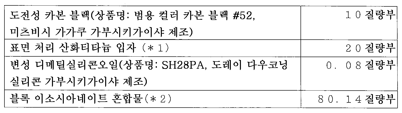
또한, 상기 표 5 중의 표면 처리 산화티타늄 입자(*1)는 이하의 방법으로 제조하였다. 즉, 침상 루틸형 산화티타늄 입자(평균 입경 15 ㎚, 세로:가로=3:1, 체적 저항률 2.3×10¹⁰Ω·㎝) 1000 g에, 표면 처리제로서 이소부틸트리메톡시실란 110 g, 용매로서 톨루엔 3000 g을 배합하여 슬러리로 하였다. 이 슬러리를 교반기로 30분간 혼합 후, 유효 내용적의 80 %가 평균 입경 0.8 ㎜의 글래스 비즈로 충전된 비스코 밀에 공급하여, 온도 35±5 ℃에서 습식 해쇄 처리를 행하였다. 얻어진 슬러리를, 니이더를 사용하여 감압 증류(배스 온도: 110 ℃, 제품 온도: 30 내지 60 ℃, 감압도: 약 100 Torr)하여, 톨루엔을 제거하고, 120 ℃에서 2시간 표면 처리제의 베이킹 처리를 행하였다. 베이킹 처리한 입자를 실온까지 냉각시킨 후, 핀 밀을 사용하여 분쇄하여, 표면 처리 산화티타늄 입자를 얻었다.In addition, the surface-treated titanium oxide particle (* 1) of the said Table 5 was manufactured with the following method. That is, to 1000 g of acicular rutile type titanium oxide particles (average particle diameter 15 nm, length: width = 3: 1, volume resistivity 2.3 x 10 10 Ω · cm) as 110 g of isobutyltrimethoxysilane as a surface treatment agent and a solvent 3000 g of toluene was mix | blended and it was set as the slurry. After mixing this slurry with a stirrer for 30 minutes, 80% of the effective volume was supplied to the biscotti mill filled with the glass beads of 0.8 mm of average particle diameters, and the wet disintegration process was performed at the temperature of 35 +/- 5 degreeC. The obtained slurry was distilled under reduced pressure (bath temperature: 110 ° C, product temperature: 30 to 60 ° C, reduced pressure: about 100 Torr) using a kneader to remove toluene, and baking treatment of the surface treatment agent at 120 ° C for 2 hours. Was performed. The baked particles were cooled to room temperature and then ground using a pin mill to obtain surface-treated titanium oxide particles.
또한, 표 5 중의 블록 이소시아네이트 혼합물(*2)은 헥사메틸렌디이소시아네이트(HDI)와 이소포론디이소시아네이트(IPDI)의 각 부타논옥심 블록체를 질량비 7:3으로 혼합한 것이다. 또한, 해당 블록 이소시아네이트 혼합물의 이소시아네이트량으로서는 「NCO/OH=0.7」가 되는 양이었다.In addition, the block isocyanate mixture (* 2) of Table 5 mixes each butanone oxime block body of hexamethylene diisocyanate (HDI) and isophorone diisocyanate (IPDI) in mass ratio 7: 3. In addition, it was a quantity used as "NCO / OH = 0.7" as an isocyanate amount of this block isocyanate mixture.
계속해서, 내용적 450 ㎖의 유리병에 상기 혼합 용액 200 g을 미디어로서의 평균 입경 0.8 ㎜의 글래스 비즈 200 g과 함께 넣고, 페인트 셰이커 분산기를 사용해서 24시간 분산시켰다. 그 후, 글래스 비즈를 여과에 의해 제거하여, 표면층 형성용 도포액 8을 얻었다. 표면층 형성용 도포액 8을 실시예 5과 마찬가지의 조건에서 딥 도포한 후, 온도 60 ℃에서 1시간으로 가열 처리하여 본 비교예에 관한 대전 롤러를 제작하였다. 이 대전 롤러 및 그 표면층을 실시예 1과 마찬가지로 하여 평가하였다.Subsequently, 200 g of the mixed solution was put together with 200 g of glass beads having an average particle diameter of 0.8 mm as the media in a 450 ml volumetric glass bottle, and dispersed for 24 hours using a paint shaker disperser. Thereafter, the glass beads were removed by filtration to obtain a coating solution 8 for forming a surface layer. After coating the coating liquid 8 for surface layer formation on the conditions similar to Example 5, it heat-processed at the temperature of 60 degreeC for 1 hour, and produced the charging roller which concerns on this comparative example. This charging roller and its surface layer were evaluated in the same manner as in Example 1.
[비교예 5][Comparative Example 5]
실시예 1에서, 표면층을 설치하지 않는 것 이외에는, 실시예 1과 마찬가지로 하여 대전 롤러를 제작하였다. 이 대전 롤러를 실시예 1과 마찬가지로 하여 평가하였다.In Example 1, the charging roller was produced like Example 1 except not having provided a surface layer. This charging roller was evaluated in the same manner as in Example 1.
실시예에서 사용한 구형 입자 및 비교예에서 구형 입자의 대체물로서 사용한 입자의 물성 등을 하기 표 6에 나타내었다.The properties of the spherical particles used in the examples and the particles used as substitutes for the spherical particles in the comparative examples are shown in Table 6 below.
상기 실시예 및 비교예에 관한 대전 롤러 및 표면층의 평가 및 측정의 결과를 하기 표 7-1 내지 7-2에 나타내었다.The results of evaluation and measurement of the charging roller and the surface layer according to the Examples and Comparative Examples are shown in Tables 7-1 to 7-2 below.
[표 6]TABLE 6

[표 7-1]Table 7-1

[표 7-2][Table 7-2]

상기 표 7-2의 결과로부터, 입자를 함유하지 않고, 표면이 조면화되어 있지 않은 비교예 1에 관한 대전 롤러는, 감광체의 표면에 토너를 고착시키는 경향이 특히 강하다. 그로 인해, 감광체의 클리닝 불량에 기인하는 화상 결함이 현저하게 발생한 것으로 생각된다.From the result of Table 7-2, the charging roller according to Comparative Example 1, which contains no particles and is not roughened, has a particularly strong tendency to fix the toner on the surface of the photoconductor. Therefore, it is thought that the image defect resulting from the cleaning failure of the photosensitive member occurred remarkably.
또한, 부정형의 실리카 입자를 사용한 비교예 2에 관한 대전 롤러는, 비교예 1에 관한 대전 롤러보다도, 평가 1의 결과는, 약간 양화되어 있다. 그러나, 감광체의 클리닝 불량에 기인하는 화상 결함은 발생하고 있다. 이것은 입자가 부정형이기 때문에, 감광체 표면이 깎여서 조도가 거칠어져, 클리닝 블레이드와 감광체간에 간극이 생겨, 토너의 빠져나감이 일어났다고 생각된다.In addition, in the charging roller which concerns on the comparative example 2 which used amorphous silica particle, the result of evaluation 1 is a little positive rather than the charging roller which concerns on the comparative example 1. However, image defects due to poor cleaning of the photosensitive member have occurred. Since the particles are irregular, the surface of the photoconductor is shaved and roughness becomes rough, a gap is formed between the cleaning blade and the photoconductor, and it is thought that the toner escapes.
이어서, 저경도의 구상 입자를 함유하는 비교예 3에 관한 대전 롤러는, 감광체와의 닙에서 감광체에 가압되었을 때, 구형 입자가 변형되고, 대전 롤러의 표면이 평탄해져 버리기 때문에, 감광체에 토너를 고착시켜 버린 것으로 생각된다.Subsequently, the charging roller according to Comparative Example 3 containing low-hardness spherical particles deforms spherical particles when the photosensitive member is pressed in the nip with the photosensitive member, and the surface of the charging roller is flattened. It seems to have stuck.
또, 비교예 4에 관한 대전 롤러는, 수지 표면층이 본 발명에 따른 표면층와 같은 강성을 갖지 않고, 유연하기 때문에, 닙에서 감광체에 가압되었을 때, 구형 입자가 탄성층에 매몰되고, 대전 롤러의 표면이 평탄해져 버리기 때문에, 감광체에 토너를 고착시켜 버린 것으로 생각된다.In addition, the charging roller according to Comparative Example 4 has a rigid surface similar to that of the surface layer according to the present invention, and is flexible, so that when the resin surface layer is pressed to the photosensitive member in the nip, the spherical particles are buried in the elastic layer, and the surface of the charging roller Since this becomes flat, it is thought that the toner is fixed to the photosensitive member.
게다가, 비교예 5에 관한 대전 롤러는, 표면층을 갖지 않기 때문에, 다수 매의 전자 사진 화상의 형성에 의해 표면이 불균일하게 마모되어, 대전 성능이 불균일해져 버린 것으로 생각된다.In addition, since the charging roller according to Comparative Example 5 does not have a surface layer, it is considered that the surface is unevenly worn by the formation of a plurality of electrophotographic images, resulting in uneven charging performance.
이 출원은 2010년 8월 20일에 출원된 일본 특허 출원 제2010-185122호부터의 우선권을 주장하는 것으로, 그 내용을 원용하여 이 출원의 일부로 하는 것이다.This application claims the priority from Japanese Patent Application No. 2010-185122 for which it applied on August 20, 2010, and uses the content as a part of this application.
10 대전 롤러(대전 부재)
11 도전성 지지체
12 탄성층
13 표면층
31 구상 입자10 charging roller (charging member)
11 conductive support
12 elastic layer
13 surface layer
31 spherical particles
Claims (2)
상기 탄성층은, 구형 입자를, 상기 구형 입자의 적어도 일부가 상기 탄성층의 표면으로부터 노출되도록 함유하여, 상기 탄성층의 표면은 조면화되고,
상기 구형 입자는, 구형 실리카 입자, 구형 알루미나 입자 및 구형 지르코니아 입자를 포함하여 이루어지는 군으로부터 선택되는 하나 이상이며,
상기 탄성층의 표면은, 상기 표면층에 의해, 상기 탄성층의 표면 형상이 상기 대전 부재의 표면 형상에 반영되도록 피복되고,
상기 표면층은, 하기 식 (1)로 나타나는 구성 단위를 갖는 고분자 화합물을 포함하는 것을 특징으로 하는 대전 부재:

식 (1) 중, R1, R2는 각각 독립하여 하기 식 (2) 내지 (5) 중 어느 것을 나타낸다.


(식 (2) 내지 (5) 중, R3 내지 R7, R10 내지 R14, R19, R20, R24 및 R25는 각각 독립하여 수소, 탄소수 1 내지 4의 알킬기, 수산기, 카르복실기 또는 아미노기를 나타낸다. R8, R9, R15 내지 R18, R22, R23, R27 내지 R30는 각각 독립하여 수소, 탄소수 1 내지 4의 알킬기를 나타낸다. n, m, l, q, s 및 t는 각각 독립하여 1 내지 8의 정수, p 및 r은 각각 독립하여 4 내지 12의 정수, x 및 y는 각각 독립하여 0 또는 1을 나타낸다. *은 식 (1) 중의 규소 원자와의 결합 위치를 나타내고, **은 식 (1) 중의 산소 원자와의 결합 위치를 나타낸다)As a charging member having a conductive support, an elastic layer and a surface layer,
The elastic layer contains spherical particles so that at least a portion of the spherical particles are exposed from the surface of the elastic layer, the surface of the elastic layer is roughened,
The spherical particles are at least one selected from the group consisting of spherical silica particles, spherical alumina particles and spherical zirconia particles,
The surface of the elastic layer is covered by the surface layer so that the surface shape of the elastic layer is reflected on the surface shape of the charging member,
The said surface layer contains the high molecular compound which has a structural unit represented by following formula (1), The charging member characterized by the above-mentioned:
In formula (1), R <1> , R <2> respectively independently represents either of following formula (2)-(5).
(In Formulas (2) to (5), R 3 to R 7 , R 10 to R 14 , R 19 , R 20 , R 24, and R 25 each independently represent hydrogen, an alkyl group having 1 to 4 carbon atoms, a hydroxyl group, and a carboxyl group. R 8 , R 9 , R 15 to R 18 , R 22 , R 23 , and R 27 to R 30 each independently represent hydrogen or an alkyl group having 1 to 4 carbon atoms. , s and t are each independently an integer of 1 to 8, p and r are each independently an integer of 4 to 12, x and y each independently represent 0 or 1. * represents a silicon atom in formula (1) and Represents a bonding position of **, and ** represents a bonding position with an oxygen atom in formula (1))
Applications Claiming Priority (3)
| Application Number | Priority Date | Filing Date | Title |
|---|---|---|---|
| JPJP-P-2010-185122 | 2010-08-20 | ||
| JP2010185122 | 2010-08-20 | ||
| PCT/JP2011/004171 WO2012023237A1 (en) | 2010-08-20 | 2011-07-25 | Charging member |
Publications (2)
| Publication Number | Publication Date |
|---|---|
| KR20130045924A true KR20130045924A (en) | 2013-05-06 |
| KR101454135B1 KR101454135B1 (en) | 2014-10-22 |
Family
ID=45604908
Family Applications (1)
| Application Number | Title | Priority Date | Filing Date |
|---|---|---|---|
| KR1020137006242A KR101454135B1 (en) | 2010-08-20 | 2011-07-25 | Charging member |
Country Status (6)
| Country | Link |
|---|---|
| US (1) | US20120076539A1 (en) |
| EP (1) | EP2607960B1 (en) |
| JP (1) | JP4878659B1 (en) |
| KR (1) | KR101454135B1 (en) |
| CN (1) | CN103080850B (en) |
| WO (1) | WO2012023237A1 (en) |
Families Citing this family (31)
| Publication number | Priority date | Publication date | Assignee | Title |
|---|---|---|---|---|
| CN102549506B (en) * | 2009-10-15 | 2014-10-29 | 佳能株式会社 | Charging member and electrophotographic device |
| KR101523857B1 (en) * | 2010-09-27 | 2015-05-28 | 캐논 가부시끼가이샤 | Electrification member, process cartridge, and electronic photographic device |
| KR101454137B1 (en) * | 2010-09-27 | 2014-10-22 | 캐논 가부시끼가이샤 | Charging member, process cartridge, and electrophotographic apparatus |
| EP2629151B1 (en) | 2010-10-15 | 2017-03-08 | Canon Kabushiki Kaisha | Charging member |
| JP4975184B2 (en) | 2010-11-11 | 2012-07-11 | キヤノン株式会社 | Charging member |
| CN103328561B (en) | 2011-01-21 | 2014-12-10 | 佳能株式会社 | Electrically conductive rubber elastomer, charging member, and electrophotographic apparatus |
| CN103597411B (en) | 2011-06-30 | 2015-09-23 | 佳能株式会社 | The manufacture method of charging member, charging member and electronic photographing device |
| JP6053354B2 (en) | 2011-07-06 | 2016-12-27 | キヤノン株式会社 | Charging member, method for manufacturing the same, and electrophotographic apparatus |
| JP5840113B2 (en) | 2011-12-06 | 2016-01-06 | キヤノン株式会社 | Manufacturing method of cylindrical member |
| CN104011601B (en) | 2011-12-22 | 2016-09-28 | 佳能株式会社 | Charging member, its manufacture method and electronic photographing device |
| CN104024957B (en) | 2011-12-28 | 2016-03-02 | 佳能株式会社 | Electrophotography component, its manufacture method, handle box and electronic photographing device |
| JP6000989B2 (en) * | 2012-02-06 | 2016-10-05 | キヤノン株式会社 | Charging member and electrophotographic apparatus |
| JP6049435B2 (en) | 2012-03-16 | 2016-12-21 | キヤノン株式会社 | Charging member, process cartridge, and electrophotographic apparatus |
| JP6066906B2 (en) * | 2012-03-29 | 2017-01-25 | キヤノン株式会社 | Electrophotographic member manufacturing method and coating solution |
| US8622881B1 (en) | 2012-09-21 | 2014-01-07 | Canon Kabushiki Kaisha | Conductive member, electrophotographic apparatus, and process cartridge |
| JP6016838B2 (en) * | 2013-04-03 | 2016-10-26 | キヤノン株式会社 | Electrophotographic roller member, process cartridge, and electrophotographic apparatus |
| JP2015028603A (en) * | 2013-07-01 | 2015-02-12 | キヤノン株式会社 | Charging device and image forming apparatus |
| EP3048489B1 (en) | 2013-09-20 | 2020-12-16 | Canon Kabushiki Kaisha | Charging member, method for manufacturing same, process cartridge, and electrophotographic device |
| US9360789B1 (en) * | 2014-11-28 | 2016-06-07 | Canon Kabushiki Kaisha | Member for electrophotography, process cartridge and image forming apparatus |
| US9599914B2 (en) | 2015-04-03 | 2017-03-21 | Canon Kabushiki Kaisha | Electrophotographic member having bow-shaped resin particles defining concavity and protrusion at surface thereof |
| EP3281064B1 (en) | 2015-04-03 | 2019-09-25 | C/o Canon Kabushiki Kaisha | Charging member, process cartridge and electrophotographic apparatus |
| KR20170024879A (en) * | 2015-08-26 | 2017-03-08 | 에스프린팅솔루션 주식회사 | Roller for image forming apparatus |
| JP6776856B2 (en) * | 2016-12-09 | 2020-10-28 | 東レ株式会社 | Pressure contact roller |
| US10203617B2 (en) | 2017-02-28 | 2019-02-12 | Canon Kabushiki Kaisha | Electrophotographic photosensitive member, process cartridge and electrophotographic apparatus |
| US10162278B2 (en) | 2017-02-28 | 2018-12-25 | Canon Kabushiki Kaisha | Electrophotographic photosensitive member, process cartridge and electrophotographic apparatus |
| JP6850205B2 (en) | 2017-06-06 | 2021-03-31 | キヤノン株式会社 | Electrophotographic photosensitive members, process cartridges and electrophotographic equipment |
| JP2019197163A (en) * | 2018-05-10 | 2019-11-14 | キヤノン株式会社 | Electrostatic roller, cartridge, and image forming device |
| JP7079741B2 (en) * | 2019-01-30 | 2022-06-02 | 住友理工株式会社 | Charging roll for electrophotographic equipment |
| US10824087B2 (en) | 2019-03-20 | 2020-11-03 | Fuji Xerox Co., Ltd. | Charging member, charging device, process cartridge, and image forming apparatus |
| US11644761B2 (en) | 2021-06-02 | 2023-05-09 | Canon Kabushiki Kaisha | Electrophotographic roller, process cartridge and electrophotographic image forming apparatus |
| JP2023058944A (en) * | 2021-10-14 | 2023-04-26 | ヒューレット-パッカード デベロップメント カンパニー エル.ピー. | Charging member including coating layer |
Family Cites Families (15)
| Publication number | Priority date | Publication date | Assignee | Title |
|---|---|---|---|---|
| JPH05232792A (en) * | 1992-02-20 | 1993-09-10 | Canon Inc | Developing device |
| JP3070899B2 (en) * | 1994-09-09 | 2000-07-31 | 沖電気工業株式会社 | Electrophotographic developing device |
| DE69525213T2 (en) * | 1994-10-18 | 2002-07-11 | Canon Kk | Charging element, method for producing a charging element, and working unit with this charging element |
| JP2005345801A (en) | 2004-06-03 | 2005-12-15 | Canon Inc | Conductive member, image forming apparatus and process cartridge |
| CN100570502C (en) * | 2004-12-28 | 2009-12-16 | 佳能株式会社 | Charging member, handle box and electronic photographing device |
| DE602005027749D1 (en) * | 2004-12-28 | 2011-06-09 | Canon Kk | CHARGER, PROCESS CARTRIDGE AND ELECTRIC PHOTOGRAPHIC DEVICE |
| US7664434B2 (en) * | 2004-12-28 | 2010-02-16 | Canon Kabushiki Kaisha | Charging member, process cartridge and electrophotographic apparatus |
| JP2008083404A (en) * | 2006-09-27 | 2008-04-10 | Fuji Xerox Co Ltd | Charging roll, process cartridge and image forming apparatus |
| JP2009151160A (en) * | 2007-12-21 | 2009-07-09 | Canon Inc | Electrophotographic charging member |
| JP2009151161A (en) * | 2007-12-21 | 2009-07-09 | Canon Inc | Charging member, process cartridge and electrophotographic apparatus |
| JP2009151159A (en) * | 2007-12-21 | 2009-07-09 | Canon Inc | Charging device |
| JP2009237463A (en) * | 2008-03-28 | 2009-10-15 | Konica Minolta Business Technologies Inc | Developing roller |
| JP2010066708A (en) * | 2008-09-12 | 2010-03-25 | Fuji Xerox Co Ltd | Process cartridge |
| JP5400408B2 (en) | 2009-02-13 | 2014-01-29 | 株式会社荏原製作所 | Current-carrying member for anode holder and anode holder |
| JP5729988B2 (en) * | 2009-12-15 | 2015-06-03 | キヤノン株式会社 | Charging member, process cartridge, and electrophotographic apparatus |
-
2011
- 2011-07-25 EP EP11817888.8A patent/EP2607960B1/en not_active Not-in-force
- 2011-07-25 WO PCT/JP2011/004171 patent/WO2012023237A1/en active Application Filing
- 2011-07-25 CN CN201180040356.2A patent/CN103080850B/en active Active
- 2011-07-25 KR KR1020137006242A patent/KR101454135B1/en active IP Right Grant
- 2011-08-19 JP JP2011179625A patent/JP4878659B1/en not_active Expired - Fee Related
- 2011-11-30 US US13/308,485 patent/US20120076539A1/en not_active Abandoned
Also Published As
| Publication number | Publication date |
|---|---|
| KR101454135B1 (en) | 2014-10-22 |
| EP2607960A4 (en) | 2015-10-07 |
| JP2012063763A (en) | 2012-03-29 |
| EP2607960B1 (en) | 2018-01-03 |
| JP4878659B1 (en) | 2012-02-15 |
| EP2607960A1 (en) | 2013-06-26 |
| CN103080850A (en) | 2013-05-01 |
| US20120076539A1 (en) | 2012-03-29 |
| WO2012023237A1 (en) | 2012-02-23 |
| CN103080850B (en) | 2015-03-25 |
Similar Documents
| Publication | Publication Date | Title |
|---|---|---|
| KR20130045924A (en) | Charging member | |
| JP5038524B2 (en) | Charging member, process cartridge, and electrophotographic apparatus | |
| JP4991961B2 (en) | Charging member, process cartridge, and electrophotographic apparatus | |
| KR100871048B1 (en) | Charging member, process cartridge, and electrophotographic apparatus | |
| KR100893985B1 (en) | Charging member, process cartridge and electrophotographic apparatus | |
| JP6000989B2 (en) | Charging member and electrophotographic apparatus | |
| JP5943696B2 (en) | Charging member, method for manufacturing charging member, electrophotographic apparatus, and process cartridge | |
| KR101201135B1 (en) | Charging member, process cartridge, and electrophotographic apparatus | |
| KR101454131B1 (en) | Charging member, method for producing same, process cartridge, and electrophotographic device | |
| WO2011080906A1 (en) | Electrifying member, process cartridge, and electro- photographic device | |
| EP2624064B1 (en) | Charging member, process cartridge, and electrophotographic apparatus | |
| EP2597524B1 (en) | Charged member, process cartridge, and electronic photograph device | |
| KR20130133841A (en) | Charging member and process for production thereof, process cartridge, and electrophotographic device | |
| WO2012023270A1 (en) | Electrification member and manufacturing method for same | |
| KR20130095761A (en) | Charging member and manufacturing method thereof | |
| JP2011138052A (en) | Composition for forming polysiloxane containing film and electrifying member |
Legal Events
| Date | Code | Title | Description |
|---|---|---|---|
| A201 | Request for examination | ||
| E701 | Decision to grant or registration of patent right | ||
| GRNT | Written decision to grant | ||
| FPAY | Annual fee payment |
Payment date: 20170925 Year of fee payment: 4 |
|
| FPAY | Annual fee payment |
Payment date: 20180928 Year of fee payment: 5 |