KR20130039711A - Golf club shaft and golf club using the same - Google Patents
Golf club shaft and golf club using the same Download PDFInfo
- Publication number
- KR20130039711A KR20130039711A KR1020120113761A KR20120113761A KR20130039711A KR 20130039711 A KR20130039711 A KR 20130039711A KR 1020120113761 A KR1020120113761 A KR 1020120113761A KR 20120113761 A KR20120113761 A KR 20120113761A KR 20130039711 A KR20130039711 A KR 20130039711A
- Authority
- KR
- South Korea
- Prior art keywords
- shaft
- tip end
- fiber
- golf club
- sheet
- Prior art date
Links
- 239000000835 fiber Substances 0.000 claims abstract description 69
- 229920000049 Carbon (fiber) Polymers 0.000 claims abstract description 50
- 239000004917 carbon fiber Substances 0.000 claims abstract description 50
- VNWKTOKETHGBQD-UHFFFAOYSA-N methane Chemical compound C VNWKTOKETHGBQD-UHFFFAOYSA-N 0.000 claims abstract description 38
- 238000005452 bending Methods 0.000 claims abstract description 31
- 229920005989 resin Polymers 0.000 claims abstract description 24
- 239000011347 resin Substances 0.000 claims abstract description 24
- 230000005484 gravity Effects 0.000 claims abstract description 13
- NLHHRLWOUZZQLW-UHFFFAOYSA-N Acrylonitrile Chemical compound C=CC#N NLHHRLWOUZZQLW-UHFFFAOYSA-N 0.000 abstract 1
- 230000006866 deterioration Effects 0.000 abstract 1
- 238000000034 method Methods 0.000 description 32
- 238000004804 winding Methods 0.000 description 19
- 239000012783 reinforcing fiber Substances 0.000 description 14
- 230000000052 comparative effect Effects 0.000 description 8
- 239000011159 matrix material Substances 0.000 description 7
- XEEYBQQBJWHFJM-UHFFFAOYSA-N Iron Chemical compound [Fe] XEEYBQQBJWHFJM-UHFFFAOYSA-N 0.000 description 4
- 238000004581 coalescence Methods 0.000 description 4
- 238000010438 heat treatment Methods 0.000 description 4
- 238000003475 lamination Methods 0.000 description 4
- 239000007769 metal material Substances 0.000 description 4
- 238000005498 polishing Methods 0.000 description 4
- 238000012360 testing method Methods 0.000 description 4
- 238000005520 cutting process Methods 0.000 description 3
- 238000013001 point bending Methods 0.000 description 3
- 238000010998 test method Methods 0.000 description 3
- 229910001069 Ti alloy Inorganic materials 0.000 description 2
- XLOMVQKBTHCTTD-UHFFFAOYSA-N Zinc monoxide Chemical compound [Zn]=O XLOMVQKBTHCTTD-UHFFFAOYSA-N 0.000 description 2
- 239000003795 chemical substances by application Substances 0.000 description 2
- 150000001875 compounds Chemical class 0.000 description 2
- 230000003247 decreasing effect Effects 0.000 description 2
- 238000013461 design Methods 0.000 description 2
- 238000011161 development Methods 0.000 description 2
- 229920001971 elastomer Polymers 0.000 description 2
- 229910052742 iron Inorganic materials 0.000 description 2
- 238000004519 manufacturing process Methods 0.000 description 2
- 238000005259 measurement Methods 0.000 description 2
- 238000007591 painting process Methods 0.000 description 2
- 238000007517 polishing process Methods 0.000 description 2
- 238000003825 pressing Methods 0.000 description 2
- 230000035807 sensation Effects 0.000 description 2
- 230000035939 shock Effects 0.000 description 2
- 230000037303 wrinkles Effects 0.000 description 2
- 244000043261 Hevea brasiliensis Species 0.000 description 1
- 229910001240 Maraging steel Inorganic materials 0.000 description 1
- 229910000831 Steel Inorganic materials 0.000 description 1
- NINIDFKCEFEMDL-UHFFFAOYSA-N Sulfur Chemical compound [S] NINIDFKCEFEMDL-UHFFFAOYSA-N 0.000 description 1
- RTAQQCXQSZGOHL-UHFFFAOYSA-N Titanium Chemical compound [Ti] RTAQQCXQSZGOHL-UHFFFAOYSA-N 0.000 description 1
- 238000010521 absorption reaction Methods 0.000 description 1
- 239000000853 adhesive Substances 0.000 description 1
- 230000001070 adhesive effect Effects 0.000 description 1
- 239000006229 carbon black Substances 0.000 description 1
- 235000009508 confectionery Nutrition 0.000 description 1
- 230000001276 controlling effect Effects 0.000 description 1
- 230000007547 defect Effects 0.000 description 1
- 238000010586 diagram Methods 0.000 description 1
- TXKMVPPZCYKFAC-UHFFFAOYSA-N disulfur monoxide Inorganic materials O=S=S TXKMVPPZCYKFAC-UHFFFAOYSA-N 0.000 description 1
- 230000000694 effects Effects 0.000 description 1
- 239000003822 epoxy resin Substances 0.000 description 1
- 239000004744 fabric Substances 0.000 description 1
- 238000005243 fluidization Methods 0.000 description 1
- 239000000463 material Substances 0.000 description 1
- 229910052751 metal Inorganic materials 0.000 description 1
- 239000002184 metal Substances 0.000 description 1
- 150000002739 metals Chemical class 0.000 description 1
- 229920003052 natural elastomer Polymers 0.000 description 1
- 229920001194 natural rubber Polymers 0.000 description 1
- 239000003921 oil Substances 0.000 description 1
- 230000002093 peripheral effect Effects 0.000 description 1
- 229920000647 polyepoxide Polymers 0.000 description 1
- 230000001105 regulatory effect Effects 0.000 description 1
- 239000010935 stainless steel Substances 0.000 description 1
- 229910001220 stainless steel Inorganic materials 0.000 description 1
- 239000010959 steel Substances 0.000 description 1
- 239000011593 sulfur Substances 0.000 description 1
- 229920001187 thermosetting polymer Polymers 0.000 description 1
- 239000010936 titanium Substances 0.000 description 1
- 229910052719 titanium Inorganic materials 0.000 description 1
- 239000002023 wood Substances 0.000 description 1
- 239000011787 zinc oxide Substances 0.000 description 1
Images


Classifications
-
- A—HUMAN NECESSITIES
- A63—SPORTS; GAMES; AMUSEMENTS
- A63B—APPARATUS FOR PHYSICAL TRAINING, GYMNASTICS, SWIMMING, CLIMBING, OR FENCING; BALL GAMES; TRAINING EQUIPMENT
- A63B53/00—Golf clubs
- A63B53/10—Non-metallic shafts
-
- A—HUMAN NECESSITIES
- A63—SPORTS; GAMES; AMUSEMENTS
- A63B—APPARATUS FOR PHYSICAL TRAINING, GYMNASTICS, SWIMMING, CLIMBING, OR FENCING; BALL GAMES; TRAINING EQUIPMENT
- A63B2209/00—Characteristics of used materials
- A63B2209/02—Characteristics of used materials with reinforcing fibres, e.g. carbon, polyamide fibres
- A63B2209/023—Long, oriented fibres, e.g. wound filaments, woven fabrics, mats
-
- Y—GENERAL TAGGING OF NEW TECHNOLOGICAL DEVELOPMENTS; GENERAL TAGGING OF CROSS-SECTIONAL TECHNOLOGIES SPANNING OVER SEVERAL SECTIONS OF THE IPC; TECHNICAL SUBJECTS COVERED BY FORMER USPC CROSS-REFERENCE ART COLLECTIONS [XRACs] AND DIGESTS
- Y10—TECHNICAL SUBJECTS COVERED BY FORMER USPC
- Y10T—TECHNICAL SUBJECTS COVERED BY FORMER US CLASSIFICATION
- Y10T428/00—Stock material or miscellaneous articles
- Y10T428/13—Hollow or container type article [e.g., tube, vase, etc.]
- Y10T428/1352—Polymer or resin containing [i.e., natural or synthetic]
- Y10T428/1369—Fiber or fibers wound around each other or into a self-sustaining shape [e.g., yarn, braid, fibers shaped around a core, etc.]
Landscapes
- Health & Medical Sciences (AREA)
- General Health & Medical Sciences (AREA)
- Physical Education & Sports Medicine (AREA)
- Golf Clubs (AREA)
Abstract
Description
본 발명은, 타구의 비거리를 향상시키는 골프 클럽 샤프트 및 이를 이용하는 골프 클럽에 관한 것이다.The present invention relates to a golf club shaft and a golf club using the same to improve the flying distance of the ball.
최근에는, 공정한 골프 시합을 개최하기 위해, 타구의 비거리의 현저한 진전은, 골프 클럽 헤드의 스프링 효과, 골프 클럽의 길이, 또는 골프 클럽 헤드의 관성 모멘트를 제어하는 것을 통해 골프 룰로 규제되고 있다. 이러한 상황에서, 타구의 비거리를 향상시키기 위해, 일본 특허 공개 제2004-201911호에서는, 예를 들어 샤프트를 룰의 범위 내에서 가능한 한 길게 한 골프 클럽을 제안하였다. 이러한 골프 클럽은 최장의 클럽 샤프트를 이용하여 골퍼에게 높은 헤드 속도를 제공한다.In recent years, in order to hold a fair golf game, the striking progress of the hitting distance of the batting is regulated by the golf rule through controlling the spring effect of the golf club head, the length of the golf club, or the moment of inertia of the golf club head. In such a situation, in order to improve the flying distance of the hitting ball, Japanese Patent Laid-Open No. 2004-201911 proposes, for example, a golf club in which the shaft is made as long as possible within the range of the rule. These golf clubs provide the golfer with high head speeds using the longest club shafts.
그러나, 이러한 긴 샤프트를 갖는 골프 클럽은, 클럽 헤드의 컨트롤이 어렵기 때문에, 클럽 페이스의 스윗스팟의 밖에서 볼을 타격하는 경향이 있다. 즉, 클럽 헤드 속도 대 타구 속도의 비인 스매시 팩터(smash factor)가 감소될 수 있다. 따라서, 종래의 골프 클럽을 이용하여 타구의 비거리를 향상시키기는 어려웠다.However, a golf club having such a long shaft tends to hit the ball outside the sweet spot of the club face because the club head is difficult to control. That is, the smash factor, which is the ratio of club head speed to shot speed, can be reduced. Therefore, it is difficult to improve the flying distance of the hitting ball using a conventional golf club.
전술한 문제를 해결하기 위해, 종래의 클럽 헤드보다 중량이 큰 클럽 헤드와 길이가 짧은 클럽 샤프트를 구비하는 골프 클럽이 제안된다. 이러한 골프 클럽은 스매시 팩터를 향상시키고, 골프 클럽의 클럽 페이스로부터 날려 보내지는 볼의 속도가 빨라질 수 있다. 그러나, 상기 골프 클럽은 큰 관성 모멘트를 갖는 경향이 있으므로, 골프 클럽을 스윙하기가 어려워, 스윙 감각이 나빠지는 경향이 있다.In order to solve the above problem, a golf club having a club head having a larger weight and a shorter club shaft than a conventional club head is proposed. Such a golf club can improve the smash factor and speed up the ball being blown away from the club face of the golf club. However, since the golf club tends to have a large moment of inertia, it is difficult to swing the golf club, and the swinging sensation tends to be bad.
본 발명의 목적은, 더 좋은 골프 스윙의 감각을 유지하면서 타구의 비거리를 향상시키는 골프 클럽 샤프트 및 이를 이용하는 골프 클럽을 제공하는 것이다.It is an object of the present invention to provide a golf club shaft and a golf club using the same, which improves the distance of the shot while maintaining a better sense of golf swing.
본 발명에 따르면, 팁단으로부터 버트단까지 연장되며 섬유 강화 수지로 제조되는 골프 클럽 샤프트로서, 중량이 30 g 내지 55 g의 범위이고, 상기 팁단과 상기 버트단 사이의 전체 길이를 LS라 하고, 상기 팁단으로부터 샤프트의 무게 중심까지의 거리를 LG라 할 때, 상기 전체 길이 LS에 대한 상기 거리 LG의 비가 0.54 내지 0.65의 범위이며, 상기 팁단으로부터 상기 버트단측으로 300 ㎜의 길이를 갖는 팁단 부분에 포함되는 섬유에는, 피치계 탄소 섬유 및 PAN계 탄소 섬유가 포함되고, 상기 팁단 부분의 섬유는, 15 중량% 내지 25 중량%의 상기 피치계 탄소 섬유와, 85 중량% 내지 75 중량%의 상기 PAN계 탄소 섬유를 포함하는 것인 골프 클럽 샤프트가 제공된다.According to the present invention, a golf club shaft extending from the tip end to the butt end and made of fiber reinforced resin, having a weight in the range of 30 g to 55 g, the total length between the tip end and the butt end is LS, When the distance from the tip end to the center of gravity of the shaft is LG, the ratio of the distance LG to the full length LS is in the range of 0.54 to 0.65, and is included in the tip end portion having a length of 300 mm from the tip end to the butt end side. The fibers to be included include pitch-based carbon fibers and PAN-based carbon fibers, and the fiber at the tip end portion includes 15 to 25 wt% of the pitch-based carbon fibers and 85 to 75 wt% of the PAN-based A golf club shaft is provided that includes carbon fiber.
본 발명의 골프 클럽 샤프트 및 이를 이용하는 골프 클럽에서는, 굽힘 강도나 충격 강도의 저하를 수반하는 일 없이, 타구의 비거리를 증대시킬 수 있다.In the golf club shaft of this invention and the golf club using the same, the flying distance of a hitting ball can be increased, without reducing bending strength or impact strength.
도 1은 본 발명의 실시형태를 보여주는 골프 클럽의 정면도이다.
도 2는 골프 클럽 샤프트의 굽힘 강성의 측정 방법을 설명하는 측면도이다.
도 3은 골프 클럽 샤프트에 포함되는 프리프레그 시트의 전개도이다.
도 4는 제1 적층 프리프레그 시트의 평면도이다.
도 5는 제2 적층 프리프레그 시트의 평면도이다.
도 6은 골프 클럽 샤프트의 "T점 강도"의 측정 방법을 설명하는 측면도이다.
도 7은 골프 클럽 샤프트의 충격 에너지의 측정 방법을 설명하는 측면도이다.
도 8은 골프 클럽 샤프트의 비틀림 강성의 측정 방법을 설명하는 측면도이다.1 is a front view of a golf club showing an embodiment of the present invention.
2 is a side view illustrating a method for measuring bending rigidity of a golf club shaft.
3 is an exploded view of a prepreg sheet included in a golf club shaft.
4 is a plan view of the first laminated prepreg sheet.
5 is a plan view of a second laminated prepreg sheet.
It is a side view explaining the measuring method of "T point strength" of a golf club shaft.
It is a side view explaining the measuring method of the impact energy of a golf club shaft.
It is a side view explaining the measuring method of torsional rigidity of a golf club shaft.
첨부 도면을 참조하여, 본 발명의 실시형태를 이하에 설명한다.EMBODIMENT OF THE INVENTION Embodiment of this invention is described below with reference to an accompanying drawing.
도 1은 본 발명의 실시형태에 따른 골프 클럽(1)의 정면도이다. 골프 클럽(1)은, 골프 클럽 헤드(2)와, 골프 클럽 샤프트(이하에서는 간단히 "샤프트"라고도 함)(3), 그리고 그립(4)을 포함한다.1 is a front view of a golf club 1 according to an embodiment of the present invention. The golf club 1 includes a
골프 클럽 헤드(2)의 중량은, 특별히 한정되는 것은 아니지만, 바람직하게는 290 g 이하, 보다 바람직하게는 287 g 이하, 더 바람직하게는 284 g 이하이고, 바람직하게는 270 g 이상, 보다 바람직하게는 273 g 이상이다. 클럽 헤드(2)의 중량이 너무 크면, 클럽 헤드 속도는 골프 스윙의 어려움으로 인하여 향상되지 않을 수 있다. 한편, 클럽 헤드(2)의 중량이 너무 작으면, 클럽 헤드의 내구성은 클럽 헤드의 강도의 저하로 인하여 나빠지는 경향이 있다.Although the weight of the
골프 클럽(1)의 길이는, 특별히 한정되는 것은 아니지만, 바람직하게는 44.0 인치 이상, 보다 바람직하게는 44.5 인치 이상, 더 바람직하게는 45.0 인치 이상으로 설정되고, 바람직하게는 47.0 인치 이하, 보다 바람직하게는 46.5 인치 이하, 더 바람직하게는 46.0 인치 이하로 설정된다. 이러한 클럽 길이를 갖는 골프 클럽은, 골퍼에게 우수한 스윙 밸런스를 제공하고, 그 길이에 기초하여 높은 스윙 속도를 제공한다.Although the length of the golf club 1 is not specifically limited, Preferably it is 44.0 inches or more, More preferably, it is set to 44.5 inches or more, More preferably, it is 45.0 inches or more, Preferably it is 47.0 inches or less, More preferably Preferably 46.5 inches or less, more preferably 46.0 inches or less. Golf clubs having such a club length provide golfers with an excellent swing balance and provide a high swing speed based on that length.
여기서, 클럽 길이는, R&A(Royal and Ancient Golf Club of Saint Andrews : 전영 골프 협회)가 공표하는 골프 룰 "부속 규칙 Ⅱ-클럽의 디자인"의 "옵션 c. 길이"에 기초하여 측정된다.Here, the club length is measured based on "option c. Length" of the golf rule "Annex Rule II-Club Design" published by the R & A (Royal and Ancient Golf Club of Saint Andrews).
예컨대, 골프 클럽 헤드(2)는, 볼을 타격하기 위한 클럽 페이스(2a)를 갖는 중공형의 본체(2A); 및 상기 본체(2A)의 힐측에 관상체로서 형성되며 클럽 샤프트(3)의 팁단(3a)이 삽입되는 호젤부(2B)를 포함하는 우드형 골프 클럽 헤드이다. 클럽 헤드(2)에는, 우드형 클럽 헤드뿐만 아니라 아이언형이나 유틸리티형 클럽 헤드도 채용될 수 있다.For example, the
클럽 헤드(2)는 하나 이상의 금속 재료로 제조된다. 이 금속 재료의 바람직한 예로는, 예를 들어 순수 티타늄, 티타늄 합금, 스테인리스강, 마레이징강, 연철 및 이들 금속의 조합 등이 있다. 또한, 도면에 도시되어 있지는 않지만, 비중이 낮은 비금속 재료, 예컨대 섬유 강화 수지 등이 클럽 헤드(2)의 일부분에 사용될 수 있다. 클럽 헤드의 무게 중심을 하측으로 옮기기 위해, 예컨대 클럽 헤드(2)는, 상측 부분의 적어도 일부가 CFRP 부재로 이루어지고, 하측 부분의 적어도 일부가 티타늄 합금으로 이루어지는 것이 바람직하다.The
클럽 헤드(2)의 중량은, 바람직하게는 185g 이상, 보다 바람직하게는 192g 이상이고, 바람직하게는 210 g 이하, 보다 바람직하게는 206 g 이하, 더 바람직하게는 203 g 이하이다. 이러한 중량을 갖는 골프 클럽 헤드(2)는, 골퍼에게 우수한 스윙 밸런스를 제공하고, 타구에 큰 운동 에너지를 전달할 수 있다.The weight of the
적절한 실시형태에서는, 골프 클럽 중량에 대한 클럽 헤드 중량의 비(클럽 헤드 중량/골프 클럽 중량)가 바람직하게는 0.670 이상, 보다 바람직하게는 0.675 이상, 더 바람직하게는 0.680 이상으로 설정되고, 바람직하게는 0.720 이하, 보다 바람직하게는 0.715 이하로 설정된다. 이러한 비를 갖는 골프 클럽(1)은, 골퍼에게 우수한 스윙 밸런스를 제공하고, 타구에 큰 운동 에너지를 전달할 수 있다.In a suitable embodiment, the ratio of club head weight to club club weight (club head weight / golf club weight) is preferably set to at least 0.670, more preferably at least 0.675, even more preferably at least 0.680, preferably Is set to 0.720 or less, more preferably 0.715 or less. The golf club 1 having such a ratio can provide a golfer with an excellent swing balance and can transmit large kinetic energy to the batting ball.
그립(4)은, 예를 들어 천연 고무, 오일, 카본 블랙, 황 및 산화아연을 함유하는 고무 화합물로 제조된다. 이 고무 화합물을 혼련하고 가황하여 소정의 그립 형상을 형성한다. 강도, 내구성 및 골프 스윙의 용이성을 유지하기 위해, 그립(4)의 중량은 바람직하게는 27 g 내지 45 g의 범위로 설정된다.The grip 4 is made of a rubber compound containing, for example, natural rubber, oil, carbon black, sulfur and zinc oxide. This rubber compound is kneaded and vulcanized to form a predetermined grip shape. In order to maintain strength, durability and ease of golf swing, the weight of the grip 4 is preferably set in the range of 27 g to 45 g.
클럽 샤프트(3)는, 클럽 헤드(2)의 호젤부(2B)에 부착되는 팁단(3a)과, 그립(4)에 부착된 버트단(3b)을 갖는다. 즉, 클럽 샤프트(3)의 팁단(3a)은 클럽 헤드(2)의 내부에 위치하고, 버트단(3b)은 그립(4)의 내부에 위치한다. 도 1에 도시된 바와 같이, 참조부호 "G"는 클럽 샤프트(3)의 무게 중심을 나타낸다. 클럽 샤프트(3)의 무게 중심은 샤프트 축선 상에 위치한다. 또한, 본 실시형태의 클럽 샤프트(3)는, 버트단(3b)으로부터 팁단(3a)측으로 외경이 줄어들면서 연장되며 원형의 단면을 갖는 테이퍼형 관상체를 포함한다.The
본 실시형태의 클럽 샤프트(3)는, 강화 섬유와, 그 안에 디핑된 강화 섬유를 고정시키는 매트릭스 수지를 포함하는 섬유 강화 수지로 제조된다. 이러한 섬유 강화 수지로 제조된 클럽 샤프트(3)는, 스틸 샤프트에 비해 경량이며, 그 굽힘 강성을 조절하기 위한 설계 유연성을 갖는다. 클럽 샤프트(3)는, 예를 들어 강화 섬유를 가열 경화 수지에 함침시킨 시트체인 프리프레그를 이용하여 시트 와인딩법으로 제조된다. 따라서, 클럽 샤프트(3)는 복수층의 강화 섬유를 포함하는 관상체를 갖는다. 도 1에 도시된 바와 같이, 클럽 샤프트(3)는, 팁단(3a)과 버트단(3b) 사이의 전체 길이 LS와, 팁단(3a)으로부터 클럽 샤프트(3)의 무게 중심(G)까지의 거리 LG를 갖는다.The
클럽 샤프트(3)의 중량(Ws)은 30 g 내지 55 g의 범위이다. 클럽 샤프트(3)의 중량(Ws)이 너무 작으면, 소정의 필요 길이를 보유하기 위해 클럽 샤프트(3)의 두께를 얇게 하기 때문에, 클럽 샤프트(3)의 강도는 나빠지는 경향이 있다. 이러한 관점에서, 클럽 샤프트(3)의 중량(Ws)은 30 g 이상, 보다 바람직하게는 32 g 이상, 더 바람직하게는 34 g 이상으로 설정된다. 한편, 클럽 샤프트(3)의 중량(Ws)이 55 g보다 크면, 이러한 클럽 샤프트(3)를 이용하는 골프 클럽(1)의 스윙 속도가 감소될 수 있다. 이러한 관점에서, 클럽 샤프트(3)의 중량(Ws)은 55g 이하, 보다 바람직하게는 54g 이하, 더 바람직하게는 53g 이하로 설정된다.The weight Ws of the
클럽 샤프트(3)의 전체 길이(LS)에 대한 거리(LG)의 비(LG/LS)는 0.54 내지 0.65의 범위이다. 즉, 본 발명에 따른 클럽 샤프트(3)는, 클럽 샤프트(3)의 무게 중심(G)이 버트단(3b) 측으로 옮겨져 있다. 이러한 골프 클럽 샤프트(3) 및 이를 이용한 골프 클럽(1)은, 중량 및 중량 밸런스가 상기와 같이 특정되어 있기 때문에, 골퍼에게 용이한 조작성을 제공하는 적절한 골프 클럽의 관성 모멘트를 확보할 수 있다. 따라서, 본 발명에 따른 클럽 샤프트(3)를 사용하는 골퍼는, 원하는 골프 스윙을 용이하게 행할 수 있다. 또한, 전체 길이(LS)가 짧은 길이로 설정되는 경우, 스매시 팩터가 향상될 수 있으므로, 타구의 비거리가 증대될 수 있다.The ratio LG / LS of the distance LG to the total length LS of the
비(LG/LS)가 0.54 미만이면, 클럽 샤프트(3)의 무게 중심(G)이 팁단(3a)에 가까워질 수 있으므로, 이러한 골프 클럽 샤프트의 경우, 골프 클럽의 스윙 밸런스를 양호하게 유지하기 위해서는, 경량의 클럽 헤드가 필요하게 될 수 있다. 일반적으로, 클럽 헤드의 중량이 작으면, 관성 모멘트는 바람직하지 못하게 작아지고, 스매시 팩터는 저하된다. 이러한 관점에서, 상기 비(LG/LS)는 바람직하게는 0.55 이상, 보다 바람직하게는 0.56 이상으로 설정된다.If the ratio LG / LS is less than 0.54, the center of gravity G of the
한편, 비(LG/LS)가 0.65보다 크면, 클럽 샤프트(3)의 무게 중심(G)이 버트단(3b)에 현저하게 가까워질 수 있으므로, 이러한 골프 클럽 샤프트의 경우, 골프 클럽의 스윙 밸런스를 양호하게 유지하기 위해서는, 무거운 클럽 헤드가 필요하게 될 수 있고, 이러한 경우의 클럽 샤프트는 팁단(3a) 측에서의 강도가 바람직하지 못하게 저하되는 경향이 있다. 이러한 관점에서, 상기 비(LG/LS)는 바람직하게는 0.64 이하, 보다 바람직하게는 0.63 이하로 설정된다.On the other hand, if the ratio LG / LS is larger than 0.65, the center of gravity G of the
클럽 샤프트(3)의 전체 길이(LS)는 특별히 한정되지는 않는다. 그러나, 전체 길이(LS)가 너무 짧으면, 골프 클럽의 스윙 반경이 작을 수 있으므로, 골프 클럽의 스윙 속도를 향상시키기가 어렵다. 한편, 전체 길이(LS)가 너무 길면, 골프 클럽(1)의 관성 모멘트가 커지는 경향이 있으므로, 골프 스윙을 하기가 어려워질 수 있다. 이러한 관점에서, 클럽 샤프트(3)의 전체 길이(LS)는 바람직하게는 105 ㎝ 이상, 보다 바람직하게는 107 ㎝ 이상, 더 바람직하게는 110 ㎝ 이상으로 설정된다. 또한, 클럽 샤프트(3)의 전체 길이(LS)는 바람직하게는 120 ㎝ 이하, 보다 바람직하게는 118 ㎝ 이하, 더 바람직하게는 116 ㎝ 이하로 설정된다.The total length LS of the
클럽 샤프트의 무게 중심(G)의 위치를 옮기기 위해, 예를 들어 클럽 샤프트의 두께 및/또는 축방향에서의 테이퍼 각도를 변경할 수 있다. 이러한 조정은, 예를 들어 프리프레그 시트(이하 참조)의 권취수를 변경함으로써 행해질 수 있다.In order to shift the position of the center of gravity G of the club shaft, for example, the thickness of the club shaft and / or the taper angle in the axial direction can be changed. Such adjustment can be made, for example, by changing the number of turns of the prepreg sheet (see below).
클럽 샤프트(3)에는, 팁단(3a)으로부터 버트단(3b) 측으로 300 ㎜의 길이를 갖는 팁단 부분(A)이 마련된다. 상기 팁단 부분에 포함되는 강화 섬유에는, 피치계 탄소 섬유 및 PAN계 탄소 섬유가 포함된다. 또한, 팁단 부분(A)의 강화 섬유는, 15 중량% 내지 25 중량%의 상기 피치계 탄소 섬유와, 85 중량% 내지 75 중량%의 상기 PAN계 탄소 섬유를 포함한다.The
굽힘 강도가 큰 PAN계 탄소 섬유를 포함하는 팁단 부분(A)은, 그 굽힘 강성의 저하가 방지될 수 있다. 한편, PAN계 탄소 섬유의 함량이 너무 높으면, 샤프트(3)의 충격 강도가 현저히 나빠지므로, 샤프트(3)의 내구성이 저하될 수 있다. 전술한 문제를 해결하려면, 충격 흡수 성능이 우수한 피치계 탄소 섬유가 팁단 부분(A)에 필요하게 되며, 이를 통해 샤프트(3)의 충격 강도의 저하가 방지되면서 팁단 부분(A)의 굽힘 강성이 유지된다. 또한, 팁단 부분(A)에 피치계 탄소 섬유를 채용하면, 그 충격 흡수 성능이 우수하므로, 볼 타격 감각이 향상될 수 있다.The tip end portion A containing the PAN-based carbon fiber having a large bending strength can be prevented from decreasing the bending rigidity. On the other hand, if the content of the PAN-based carbon fiber is too high, the impact strength of the
여기서, PAN계 탄소 섬유는 팁단 부분(A)의 전체 섬유 중에 85 중량% 내지 75 중량%로 포함된다. 한편, 팁단 부분(A)에서의 PAN계 탄소 섬유의 함량이 75 중량% 미만이면, 샤프트(3)의 내구성은 팁단 부분(A)의 굽힘 강도 저하로 인하여 나빠지는 경향이 있다. 한편, PAN계 탄소 섬유의 함량이 85 중량%보다 크면, 볼 타격 감각 및 샤프트(3)의 충격 강도가 현저히 나빠지는 경향이 있다. 이러한 견지에서, 팁단 부분(A)의 전체 섬유에 있어서 PAN계 탄소 섬유의 함량은 바람직하게는 76 중량% 이상, 더 바람직하게는 77 중량% 이상이고, 바람직하게는 84 중량% 이하, 더 바람직하게는 83 중량% 이하이다.Here, the PAN-based carbon fiber is included in the 85% to 75% by weight of the total fiber of the tip end portion (A). On the other hand, if the content of the PAN-based carbon fiber in the tip end portion A is less than 75% by weight, the durability of the
상기 피치계 탄소 섬유는 팁단 부분(A)의 전체 섬유 중에 15 중량% 내지 25 중량%로 포함된다. 팁단 부분(A)에서의 피치계 탄소 섬유의 함량이 15 중량 미만이면, 볼 타격 감각 및 샤프트(3)의 충격 강도가 현저히 나빠지는 경향이 있다. 한편, 상기 피치계 탄소 섬유의 함량이 25 중량%보다 크면, 샤프트(3)의 내구성은 팁단 부분(A)의 굽힘 강도 저하로 인하여 나빠지는 경향이 있다. 이러한 견지에서, 팁단 부분(A)의 전체 섬유에 있어서 피치계 탄소 섬유의 함량은 바람직하게는 16 중량% 이상, 더 바람직하게는 17 중량% 이상이고, 바람직하게는 24 중량% 이하, 더 바람직하게는 23 중량% 이하이다. 또한, 상기 피치계 탄소 섬유의 탄성률은 바람직하게는 10 t/㎟ 이하로 설정된다.The pitch-based carbon fiber is included in 15% by weight to 25% by weight in the total fiber of the tip end portion (A). If the content of the pitch-based carbon fiber in the tip end portion A is less than 15 weights, the ball striking feeling and the impact strength of the
본 발명의 바람직한 양태에서, 팁단 부분(A)에 포함된 PAN계 탄소 섬유는, 샤프트(3)의 축방향에 평행한 스트레이트 섬유를 포함하고, 상기 스트레이트 섬유는, 팁단 부분(A)의 전체 섬유 중에 바람직하게는 50 중량% 이상, 보다 바람직하게는 51 중량% 이상, 더 바람직하게는 52 중량% 이상으로 함유되어 있다. 스트레이트 섬유는 팁단 부분(A)의 굽힘 강도를 효과적으로 향상시킨다. 한편, 스트레이트 섬유의 함량(중량%)이 너무 크면, 팁단 부분(A)의 비틀림 강성이 저하되는 경향이 있다. 따라서, 팁단 부분(A)에 있어서 스트레이트 섬유의 함량은, 팁단 부분(A)의 전체 섬유 중에 바람직하게는 80 중량% 이하, 보다 바람직하게는 79 중량%, 더 바람직하게는 78 중량% 이하이다. 특히, 스트레이트 섬유의 탄성률은 바람직하게는 24 t/㎟ 내지 30 t/㎟의 범위로 설정된다.In a preferred embodiment of the present invention, the PAN-based carbon fiber included in the tip end portion A includes straight fibers parallel to the axial direction of the
본 발명의 바람직한 양태에서, 팁단 부분(A)에 포함된 PAN계 탄소 섬유는, 샤프트의 축방향에 대하여 45도±5도의 각도를 이루며 경사진 바이어스 섬유를 포함하고, 이 바이어스 섬유는 팁단 부분(A)의 전체 섬유 중에 5 중량% 내지 25 중량%의 범위로 함유되어 있다. 이 바이어스 섬유는, 팁단 부분(A)의 비틀림 강성 및 강도 양자 모두를 균형 잡힌 방식으로 향상시킨다. 팁단 부분(A)의 전체 섬유 중에서의 바이어스 섬유의 함량이 5 중량% 미만이면, 팁단 부분(A)의 비틀림 강성을 향상시키기가 어렵다. 이러한 견지에서, 상기 바이어스 섬유의 함량은, 팁단 부분(A)의 전체 섬유 중에 바람직하게는 6 중량% 이상, 더 바람직하게는 7 중량% 이상이다. 한편, 바이어스 섬유의 함량(중량%)이 너무 크면, 팁단 부분(A)의 굽힘 강성이 저하되는 경향이 있다. 이러한 견지에서, 상기 바이어스 섬유의 함량은 바람직하게는 25 중량% 이하, 보다 바람직하게는 24 중량% 이하, 더 바람직하게는 23 중량% 이하이다. 또한, 바이어스 섬유의 탄성률은 바람직하게는 40 t/㎟ 내지 60 t/㎟의 범위로 설정된다.In a preferred embodiment of the present invention, the PAN-based carbon fiber included in the tip end portion A includes an inclined bias fiber at an angle of 45 degrees ± 5 degrees with respect to the axial direction of the shaft, and the bias fiber comprises a tip end portion ( It is contained in the range of 5 weight%-25 weight% in the total fiber of A). This bias fiber improves both the torsional rigidity and the strength of the tip end portion A in a balanced manner. If the content of the bias fiber in the total fibers of the tip end portion A is less than 5% by weight, it is difficult to improve the torsional rigidity of the tip end portion A. In this respect, the content of the bias fiber is preferably at least 6% by weight, more preferably at least 7% by weight, in the total fibers of the tip end portion (A). On the other hand, when the content (weight%) of the bias fiber is too large, the bending stiffness of the tip end portion A tends to be lowered. In this respect, the content of the bias fiber is preferably 25% by weight or less, more preferably 24% by weight or less, even more preferably 23% by weight or less. Further, the elastic modulus of the bias fiber is preferably set in the range of 40 t /
본 발명에서, 샤프트(3)의 팁단 부분(A) 이외의 사양은 특별히 한정되지 않는다. 따라서, 샤프트(3)의 다른 사양은 관례에 따라 설정될 수 있다. 바람직한 실시형태의 일 양태에서는, 샤프트(3)의 팁단(3a)으로부터 100 ㎜ 길이의 위치(P1)에서의 샤프트(3)의 굽힘 강성(EI)이 2.0 kgf㎡ 이하이다.In the present invention, specifications other than the tip end portion A of the
도 2에 도시된 바와 같이, 샤프트(3)의 굽힘 강성(EI)은 만능 재료 시험기(INTESCO Co., Ltd.에서 제조한 모델-2020)를 이용하여 측정된다. 이 측정법에서, 샤프트(3)는 2개의 지지 지그(J1 및 J2)를 이용하여 수평하게 지지되며, 상기 두 지지 지그 사이의 너비(스팬)는 200 ㎜이다. 이러한 상태에서, 샤프트(3)에서의 위치(P1)가 상기 스팬의 중심(C)에 위치하도록, 지지 지그(J1 및 J2)를 조정한다. 이어서, 굽힘 강성의 값(EI)을 측정하는 위치(P1)에, 하중(F)을 하방으로 가한다. 보다 구체적으로, 5 ㎜/분의 하중 인가 속도에서 하중(F)이 20 kgf에 달하는 경우, 하중 인가부(J3)가 정지된다. 이때, 샤프트(3)의 휨량을 측정한다. 지지 지그(J1 및 J2)의 단면 형상에서 팁의 곡률 반경은 12.5 ㎜이며, 하중 인가부(J3)의 단면에서 팁의 곡률 반경은 5 ㎜이다. 이하의 식을 이용하여 굽힘 강성(EI)을 산출한다.As shown in FIG. 2, the bending stiffness (EI) of the
굽힘 강성 EI = (최대 하중 F x (지그 사이의 너비)3)/(48 x 휨량)Bending rigidity EI = (maximum load F x (width between jigs) 3) / (48 x deflection)
굽힘 강성(EI)을 측정하는 위치(P1)는 클럽 헤드(2)의 근방에 위치해 있다. 따라서, 샤프트(3)의 위치 P1에서의 굽힘 강성(EI)이 2.0 kgf㎡보다 큰 경우, 이와 같이 굽힘 강성이 큰 샤프트를 구비한 골프 클럽은 골프 스윙 중에 충분히 휘지 않을 수 있으므로, 타구가 더 높이 올라가지 않을 수 있고, 타구의 비거리가 저하되는 경향이 있다. 따라서, 위치 P1에서의 굽힘 강성(EI)은 바람직하게는 1.9 kgf㎡ 이하, 더 바람직하게는 1.8 kgf㎡ 이하이다. 한편, 샤프트(3)의 위치 P1에서의 굽힘 강성(EI)이 너무 작은 경우, 이와 같이 굽힘 강성이 작은 샤프트를 구비한 골프 클럽은 골프 스윙 중에 과도하게 휘어질 수 있으므로, 타구가 원하지 않은 방향으로 폭넓게 분산될 수 있고, 타구의 비거리가 저하되는 경향이 있다. 따라서, 위치 P1에서의 굽힘 강성(EI)은 바람직하게는 0.8 kgf㎡ 이상, 보다 바람직하게는 0.9 kgf㎡ 이상, 더 바람직하게는 1.0 kgf㎡ 이상이다.The position P1 for measuring the bending stiffness EI is located near the
클럽 샤프트(3)는 프리프레그를 이용하여 소위 시트 와인딩법으로 제조되는 것이 바람직하다. 본 실시형태에서는, 상기 시트 와인딩법에, 프리프레그 시트로서, 각 섬유가 실질적으로 한 방향으로 배향된 UD 프리프레그 시트가 채용될 수 있다. 용어 "UD"는 단일 방향을 나타낸다. 그러나, UD 프리프레그 이외의 프리프레그 시트가 사용될 수도 있다. 예를 들어, 섬유가 짜여진 클로스 프리프레그가 사용될 수 있다.The
프리프레그 시트는, 예를 들어 탄소 섬유 등의 섬유와 에폭시 수지를 포함하는 열경화성 수지 등의 매트릭스 수지를 갖는다. 프리프레그의 상태에서, 매트릭스 수지는 반경화 상태를 포함하는 비경화 상태이다. 클럽 샤프트(3)의 내경과 동일한 직경을 갖는 맨드릴 둘레에 프리프레그를 권취하고 경화시킴으로써, 클럽 샤프트(3)가 만들어진다. 상기 경화는 가열에 의해 이루어진다.The prepreg sheet has matrix resins, such as thermosetting resin containing fiber, such as carbon fiber, and an epoxy resin, for example. In the state of the prepreg, the matrix resin is an uncured state including a semi-cured state. The
프리프레그 시트로서, 시판중인 여러 제품이 사용될 수 있다. 표 1은 몇몇 프리프레그 시트의 제품을 보여준다.As the prepreg sheet, various commercially available products can be used. Table 1 shows the products of some prepreg sheets.

도 3은 본 발명의 일 실시형태에 따른 클럽 샤프트(3)를 구성하는 프리프레그 시트의 전개도(시트 구성도)이다. 클럽 샤프트(3)는 복수의 프리프레그 시트(a)를 포함한다. 본원에서, 도 3에 도시된 전개도는 샤프트의 반경 방향 내측에서부터 순서대로 샤프트를 구성하는 시트를 보여준다. 프리프레그 시트는 상기 전개도에서 위에 위치하는 시트에서부터 순서대로 맨드릴의 둘레에 권취된다. 도 3의 전개도에서, 도면의 수평 방향은 클럽 샤프트의 축방향에 대응하며, 도면의 우측은 팁단(3a)측에, 도면의 좌측은 클럽 샤프트의 버트단(3b)측에 각각 대응한다. 또한, 각 프리프레그 시트(a)는 샤프트(3)의 축방향에 있어서 프리프레그 시트가 권취되는 위치에 도시되어 있다.3 is a developed view (seat configuration diagram) of the prepreg sheet constituting the
본 발명의 일 실시형태에 따른 프리프레그 시트(a)는 스트레이트 시트, 바이어스 시트 및 후프 시트를 포함한다.The prepreg sheet a according to one embodiment of the present invention includes a straight sheet, a bias sheet and a hoop sheet.
스트레이트 시트는, 클럽 샤프트의 축방향에 대해 실질적으로 0도의 각도로 배향된 강화 섬유를 갖는다. 여기서, 상기 섬유에서의 "실질적으로 0도"는, 클럽 샤프트의 축방향에 대한 섬유의 배향 각도가 ±10도 이내인 것을, 바람직하게는 클럽 샤프트의 축방향에 대한 섬유의 배향 각도가 ±5도 이내인 것을 의미한다. 스트레이트 시트의 경화 이후에, 스트레이트 시트에서의 강화 섬유의 배향 각도는 상기한 각도의 범위로 유지된다. 본 실시형태에서, 각 시트(a1, a4, a5, a6, a7, a9, a10 및 a11)는 스트레이트 시트로서 형성되어 있다. 이들 스트레이트 시트는 샤프트의 굽힘 강성 및 강도와의 연관성이 크기 때문에, 클럽 샤프트(3)의 메인 부분은 스트레이트 시트로 구성된다.The straight sheet has reinforcing fibers oriented at an angle of substantially 0 degrees with respect to the axial direction of the club shaft. Here, "substantially 0 degrees" in the fiber means that the angle of the fiber's orientation with respect to the axial direction of the club shaft is within ± 10 degrees, preferably that the fiber's orientation angle with respect to the axial direction of the club shaft is ± 5 degrees. It means within degrees. After curing of the straight sheet, the orientation angle of the reinforcing fibers in the straight sheet is maintained in the range of the above-described angles. In this embodiment, each sheet a1, a4, a5, a6, a7, a9, a10 and a11 is formed as a straight sheet. Since these straight sheets have a high correlation with the bending stiffness and strength of the shaft, the main part of the
바이어스 시트는, 클럽 샤프트의 축방향에 대해 소정의 각도로 배향된 강화 섬유를 갖는다. 따라서, 전술한 바이어스 섬유는, 경화 이후의 바이어스 시트에서의 강화 섬유로 구성된다. 본 실시형태에서, 각 시트(a2 및 a3)는 바이어스 시트로서 형성되어 있다. 바이어스 시트(a2)는 샤프트의 축방향에 대하여 -45도의 각도로 배향된 강화 섬유를 갖고, 바이어스 시트(a3)는 샤프트의 축방향에 대하여 +45도의 각도로 배향된 강화 섬유를 갖는다. 즉, 바이어스 시트(a2) 및 바이어스 시트(a3)는 서로 반대 방향을 향하며 동일한 각도로 배향된 강화 섬유를 갖는다. 이러한 바이어스 시트의 쌍은, 섬유가 반대 방향으로 배향되어 있기 때문에, 클럽 샤프트의 비틀림 강성 및 강도를 향상시키기 위해 마련되는 것이 바람직하다. 또한, 바이어스 시트의 쌍은 클럽 샤프트의 강도의 이방성을 감소시킬 수 있다.The bias sheet has reinforcing fibers oriented at an angle with respect to the axial direction of the club shaft. Therefore, the above-mentioned bias fiber is comprised with the reinforcing fiber in the bias sheet after hardening. In this embodiment, each sheet a2 and a3 is formed as a bias sheet. The bias sheet a2 has reinforcing fibers oriented at an angle of -45 degrees with respect to the axial direction of the shaft, and the bias sheet a3 has reinforcing fibers oriented at an angle of +45 degrees with respect to the axial direction of the shaft. That is, the bias sheet a2 and the bias sheet a3 have reinforcing fibers facing in opposite directions and oriented at the same angle. These pairs of bias sheets are preferably provided to improve the torsional rigidity and strength of the club shaft, since the fibers are oriented in the opposite direction. In addition, the pair of bias sheets can reduce the anisotropy of the strength of the club shaft.
후프 시트는, 클럽 샤프트의 축방향에 대해 실질적으로 90도의 각도로 배향된 강화 섬유를 갖는다. 시트(a8)가 후프 시트이다. 여기서, 상기 섬유에서의 "실질적으로 90도"는, 클럽 샤프트의 축방향에 대한 섬유의 배향 각도가 90도±10도인 것을 의미한다.The hoop sheet has reinforcing fibers oriented at an angle of substantially 90 degrees with respect to the axial direction of the club shaft. The sheet a8 is a hoop sheet. Here, "substantially 90 degrees" in the fibers means that the orientation angle of the fibers relative to the axial direction of the club shaft is 90 degrees ± 10 degrees.
이 후프 시트는, 클럽 샤프트(3)의 파쇄 강성 및 강도를 향상시키기 위해 마련된다. 파쇄 강성 및 강도는, 클럽 샤프트를 그 반경 방향 내측을 향해 눌러 부수는 힘에 대한 강성 및 강도이다. 파쇄 강도는 파쇄 변형을 발생시키는 굽힘 변형에 연동될 수 있다. 특히 얇고 경량인 샤프트에서는, 이러한 연동성이 크다. 또한, 파쇄 강도의 향상을 통해, 굽힘 강도가 향상된다.This hoop sheet is provided in order to improve the breaking rigidity and strength of the
각 프리프레그 시트는 와인딩에 사용되기 전에 커버 시트의 사이에 끼워진다. 커버 시트는, 프리프레그 시트의 일면에 점착된 이형지와, 프리프레그 시트의 타면에 점착된 수지 필름을 포함한다. 상기 이형지의 굽힘 강성은 상기 수지 필름의 굽힘 강성보다 크다. 이하에서, 이형지가 점착되어 있는 면을 "이형지측의 면"이라 하고, 수지 필름이 점착되어 있는 면을 "필름측의 면"이라고 한다. 또한, 도 3의 전개도에서는, 필름측의 면이 앞면이다. 즉, 도 3의 전개도에서, 도면의 앞면이 프리프레그 시트의 필름측의 면이고, 도면의 뒷면이 프리프레그 시트의 이형지측의 면이다.Each prepreg sheet is sandwiched between cover sheets before being used for winding. The cover sheet includes a release paper adhered to one surface of the prepreg sheet and a resin film adhered to the other surface of the prepreg sheet. The bending rigidity of the release paper is greater than the bending rigidity of the resin film. Hereinafter, the surface on which release paper is stuck is called "the surface on the release paper side", and the surface on which the resin film is stuck is called "the surface on the film side." In addition, in the expanded view of FIG. 3, the film side surface is a front surface. That is, in the developed view of FIG. 3, the front side of the drawing is the surface of the film side of the prepreg sheet, and the rear side of the drawing is the surface of the release paper side of the prepreg sheet.
도 3의 상태에서, 시트(a2)의 섬유 배향 방향은 시트(a3)의 섬유 배향 방향과 동일하다. 그러나, 후술하는 그 적층 상태에서, 시트(a3)가 뒤집히므로, 시트(a2)와 시트(a3)의 섬유 배향 방향은 서로 반대가 된다. 이 점을 고려하여, 도 3에서 시트(a2)의 섬유 배향 방향은 "-45도"로 기재되어 있고, 시트(a3)의 섬유 배향 방향은 "+45도"로 기재되어 있다.In the state of FIG. 3, the fiber orientation direction of the sheet a2 is the same as the fiber orientation direction of the sheet a3. However, in the lamination state described later, since the sheet a3 is turned over, the fiber orientation directions of the sheet a2 and the sheet a3 are opposite to each other. In view of this, the fiber orientation direction of the sheet a2 is described as "-45 degree" in FIG. 3, and the fiber orientation direction of the sheet a3 is described as "+45 degree".
프리프레그 시트(a)를 맨드릴 둘레에 권취하기 위해, 프리프레그 시트(a)로부터 그 위에 점착된 수지 필름을 박리한다. 수지 필름을 박리함으로써, 비경화 매트릭스 수지에 기인하는 점착성을 갖는 필름측의 면이 노출된다. 이어서, 프리프레그 시트(a)의 필름측의 면에 있어서 점착성을 갖는 가장자리부를 맨드릴에 부착한 후, 프리프레그 시트(a)로부터 이형지를 박리하면서 맨드릴을 회전시킴으로써, 프리프레그 시트(a)를 맨드릴 둘레에 권취한다.In order to wind the prepreg sheet a around the mandrel, the resin film adhered thereon is peeled off from the prepreg sheet a. By peeling a resin film, the surface by the side of the film which has adhesiveness resulting from an uncured matrix resin is exposed. Next, after attaching the edge part which has adhesiveness to the mandrel in the film side surface of a prepreg sheet (a), a mandrel of a prepreg sheet (a) by rotating a mandrel, peeling a release paper from the prepreg sheet (a) Wind around
전술한 프리프레그의 권취 단계에서, 이형지는 프리프레그 시트를 지지하고 그 굽힘 저항성을 향상시키므로, 권취 동안에 프리프레그 시트에서 주름이 방지될 수 있다. 따라서, 전술한 단계에 기초하여 프리프레그 시트를 권취함으로써, 프리프레그의 가장자리에서 발생되는 주름 등의 불량을 방지할 수 있으므로, 클럽 샤프트의 품질이 향상될 수 있다.In the winding step of the prepreg described above, the release paper supports the prepreg sheet and improves its bending resistance, so that wrinkles can be prevented in the prepreg sheet during winding. Therefore, by winding the prepreg sheet based on the above-described steps, defects such as wrinkles generated at the edges of the prepreg can be prevented, so that the quality of the club shaft can be improved.
2장 이상의 프리프레그 시트를 맨드릴에 권취하기 전에 중첩한 합체 프리프레그 시트가 바람직하게 채용될 수 있다. 본 실시형태에서는, 도 4와 도 5에 도시된 바와 같이 두 타입의 합체 프리프레그 시트가 채용된다. 도 4는 2개의 바이어스 시트(a2 및 a3)를 서로 결합한 제1 합체 시트(a23)를 보여준다. 도 5는 후프 시트(a8) 및 스트레이트 시트(a9)를 서로 결합한 제2 합체 시트(a89)를 보여준다.A laminated prepreg sheet superimposed before winding two or more prepreg sheets onto the mandrel may be preferably employed. In this embodiment, as shown in Figs. 4 and 5, two types of coalescing prepreg sheets are employed. 4 shows a first coalescing sheet a23 in which two bias sheets a2 and a3 are joined to each other. FIG. 5 shows a second coalescing sheet a89 in which the hoop sheet a8 and the straight sheet a9 are bonded to each other.
도 4에 도시된 제1 합체 시트(a23)는, 바이어스 시트(a3)를 뒤집는 단계; 및 이 뒤집은 바이어스 시트(a3)를 바이어스 시트(a2)에 부착하는 단계를 이용하여 제조된다. 본 실시형태에서는, 도 4에 도시된 바와 같이, 바이어스 시트(a3)의 버트단측의 가장자리가 바이어스 시트(a2)의 상측 가장자리로부터 24 ㎜의 거리에 위치하며, 바이어스 시트(a3)의 팁단측의 가장자리가 바이어스 시트(a2)의 상측 가장자리로부터 10 ㎜의 거리에 위치한다. 즉, 바이어스 시트(a2) 및 바이어스 시트(a3)의 각각의 상측 가장자리는 서로 평행하지 않다.The first coalescing sheet a23 shown in FIG. 4 includes: inverting the bias sheet a3; And attaching the inverted bias sheet a3 to the bias sheet a2. In this embodiment, as shown in FIG. 4, the butt end side of the bias sheet a3 is located at a distance of 24 mm from the upper edge of the bias sheet a2, and is located at the tip end side of the bias sheet a3. The edge is located at a distance of 10 mm from the upper edge of the bias sheet a2. That is, the upper edges of each of the bias sheet a2 and the bias sheet a3 are not parallel to each other.
제1 합체 시트(a23)에서는, 바이어스 시트(a2)와 바이어스 시트(a3) 사이의 둘레 방향의 차이가, 경화된 클럽 샤프트에 대해 약 180도±15도의 원주 각도에 상당한다. 이러한 제1 합체 시트(a23)는 각 프리프레그 시트에 있어서 강화 섬유의 단부를 분산시키기에 유용하므로, 샤프트의 둘레 방향에 따른 균일성이 향상된다.In the first coalescing sheet a23, the difference in the circumferential direction between the bias sheet a2 and the bias sheet a3 corresponds to a circumferential angle of about 180 degrees ± 15 degrees with respect to the cured club shaft. Since this first coalescence sheet a23 is useful for dispersing the end portions of the reinforcing fibers in each prepreg sheet, the uniformity along the circumferential direction of the shaft is improved.
도 5에 도시된 바와 같이, 제2 합체 시트(a89)에서 후프 시트(a8) 및 스트레이트 시트(a9)의 상측 가장자리는 서로 일치하고 있다. 또한, 후프 시트(a8)의 팁단측의 가장자리와 버트단측의 가장자리는 모두 스트레이트 시트(a9)로부터 내측에 위치해 있다. 본 실시형태에서는, 도 5에 도시된 바와 같이, 후프 시트(a8)와 스트레이트 시트(a9)의 양측에서의 가장자리 사이의 차이가 약 15 ㎜이다. 따라서, 후프 시트(a8)는 스트레이트 시트(a9)에서 완전하게 지지된다. 기본적으로, 강화 섬유가 축방향에 대하여 큰 각도를 이루며 놓여 있는 후프 시트(a8)를 맨드릴 상에 권취하는 것은 어렵다. 그러나, 전술한 바와 같이 후프 시트(a8)가 스트레이트 시트(a9) 상에 완전하게 지지되어 있는 합체 시트(a89)를 맨드릴 상에 권취하는 것은 용이하므로, 후프 시트(a8)의 권취 불량이 방지된다.As shown in FIG. 5, the upper edges of the hoop sheet a8 and the straight sheet a9 in the second coalescing sheet a89 coincide with each other. In addition, both the edge of the tip end side of the hoop sheet a8 and the edge of the butt end side are located inward from the straight sheet a9. In this embodiment, as shown in FIG. 5, the difference between the edges at both sides of the hoop sheet a8 and the straight sheet a9 is about 15 mm. Thus, the hoop sheet a8 is completely supported by the straight sheet a9. Basically, it is difficult to wind the hoop sheet a8 on which the reinforcing fibers lie at a large angle with respect to the axial direction on the mandrel. However, as mentioned above, since it is easy to wind up the coalescence sheet a89 on which the hoop sheet a8 is completely supported on the straight sheet a9 on the mandrel, the winding failure of the hoop sheet a8 is prevented. .
이어서, 도 3에 도시된 프리프레그 시트(a)를 이용한 샤프트(3)의 제조 방법을 설명한다. 본 실시형태에 따른 방법은, (1) 재단 공정; (2) 적층 공정; (3) 권취 공정; (4) 테이프 랩핑 공정; (5) 경화 공정; (6) 맨드릴 취출 공정 및 랩핑 테이프 제거 공정; (7) 양단 커트 공정; (8) 연마 공정; 및 (9) 도장 공정을 포함한다.Next, the manufacturing method of the
(1) 재단 공정:(1) Foundation process:
재단 공정에서는, 미가공 시트체를 도 3에 도시된 바와 같이 원하는 형상으로 재단함으로써, 각 프리프레그 시트(a1~a11)를 마련한다.In the cutting step, the prepreg sheets a1 to a11 are prepared by cutting the raw sheet into a desired shape as shown in FIG. 3.
(2) 적층 공정:(2) lamination process:
적층 공정에서는, 복수의 프리프레그 시트를 결합함으로써, 합체 시트(a23 및 a89)를 마련한다. 복수의 프리프레그 시트를 합체시키기 위해, 가열 및/또는 가압 공정이 채용될 수 있다. 프리프레그 시트의 접착 강도를 향상시키기 위해, 가열 공정에서의 온도 및/또는 가압 공정에서의 압력 등의 적정 파라미터가 선택될 수 있다.In a lamination process, coalescing sheets a23 and a89 are prepared by combining a plurality of prepreg sheets. In order to coalesce a plurality of prepreg sheets, a heating and / or pressing process may be employed. In order to improve the adhesive strength of the prepreg sheet, appropriate parameters such as temperature in the heating process and / or pressure in the pressing process may be selected.
(3) 권취 공정:(3) winding process:
이 공정에서는 전형적으로 금속 재료로 제조되는 맨드릴이 채용된다. 이 맨드릴의 외면에는 이형제가 사전에 도포되어 있고, 이 이형제의 외측에 수지(택킹 레진)가 배치되어 있다. 권취 공정에서는, 이 맨드릴의 둘레에 프리프레그 시트(a)가 각각 권취된다. 택킹 수지는, 그 점착성으로 인하여 프리프레그 시트의 권취 시작 가장자리를 맨드릴에 고정시키는 데 유용하다. 또한, 제1 합체 시트(a23) 및 제2 합체 시트(a89) 각각은 합체된 상태로 권취된다. 권취 공정 이후에는, 맨드릴 상에 복수의 프리프레그 시트가 권취되어 있는 권취체가 얻어진다.In this process a mandrel, typically made of a metallic material, is employed. A release agent is previously applied to the outer surface of the mandrel, and a resin (tacking resin) is disposed outside the release agent. In the winding-up step, the prepreg sheet a is wound around this mandrel, respectively. The tacky resin is useful for fixing the winding start edge of the prepreg sheet to the mandrel due to its tackiness. In addition, each of the first coalescence sheet a23 and the second coalescence sheet a89 is wound in a coalesced state. After the winding-up step, a winding body in which a plurality of prepreg sheets are wound on a mandrel is obtained.
(4) 테이프 랩핑 공정:(4) Tape Wrapping Process:
테이프 랩핑 공정에서는, 상기 권취체의 외주면 둘레에 테이프를 권취한다. 이 테이프를 랩핑 테이프라고도 한다. 안에 포함된 공기를 배출하기 위해 상기 랩핑 테이프를 장력을 부여하면서 권취하여 상기 권취체에 압력을 가함으로써, 경화된 클럽 샤프트에 보이드가 발생되는 것을 방지할 수 있다.In a tape lapping process, a tape is wound around the outer peripheral surface of the said winding body. This tape is also called a wrapping tape. It is possible to prevent the occurrence of voids in the cured club shaft by winding the wrapping tape while applying tension to pressurize the winding body to discharge the air contained therein.
(5) 경화 공정:(5) curing process:
경화 공정에서는, 테이프 랩핑을 행한 후의 권취체를 가열한다. 이러한 가열로, 매트릭스 수지는 경화된 수지 적층체를 형성하도록 경화된다. 이 경화 공정에서, 매트릭스 수지는 일시적으로 유동화된다. 이러한 매트릭스 수지의 유동화를 통해, 프리프레그 시트의 사이에 또는 시트 내에 있는 공기가 배출될 수 있다. 이러한 공기의 배출은, 랩핑 테이프로부터 가해진 압력에 의해 촉진된다.In the hardening process, the winding body after tape lapping is heated. With this heating, the matrix resin is cured to form a cured resin laminate. In this curing process, the matrix resin is temporarily fluidized. Through this fluidization of the matrix resin, air in between or within the prepreg sheet can be discharged. This release of air is facilitated by the pressure applied from the wrapping tape.
(6) 맨드릴 취출 공정 및 랩핑 테이프 제거 공정:(6) Mandrel take-out process and lapping tape removal process:
경화 공정 이후에, 맨드릴 취출 공정 및 랩핑 테이프 제거 공정이 행해진다. 상기 두 공정의 순서는 한정되지 않는다. 그러나, 랩핑 테이프 제거 공정의 능률을 향상시키는 견지에서, 맨드릴 취출 공정 이후에 랩핑 테이프 제거 공정을 행하는 것이 바람직하다.After the curing step, a mandrel take-out step and a lapping tape removal step are performed. The order of the two processes is not limited. However, from the standpoint of improving the efficiency of the lapping tape removing step, it is preferable to perform the lapping tape removing step after the mandrel take-out step.
(7) 양단 커트 공정:(7) both ends cut process:
본 공정에서는, 경화된 적층체의 양단부가 커트된다. 이러한 커트에 의해, 샤프트의 팁단(3a) 및 버트단(3b)이 형성된다. 이러한 커트에 의해, 팁단(3a)의 단부면 및 버트단(3b)의 단부면이 평탄해진다.In this step, both ends of the cured laminate are cut. By this cut, the
(8) 연마 공정:(8) Polishing Process:
본 공정에서는, 경화된 적층체의 표면을 연마한다. 이러한 연마를 표면 연마라고도 한다. 랩핑 테이프의 흔적으로서 남겨지는 나선형 요철이, 상기 경화된 적층체의 표면에 존재할 수 있다. 상기 경화된 적층체의 표면을 평탄화하기 위해, 연마에 의하여 랩핑 테이프의 흔적인 상기 요철을 없앤다.In this step, the surface of the cured laminate is polished. This polishing is also called surface polishing. Spiral irregularities that remain as traces of the lapping tape may be present on the surface of the cured laminate. In order to flatten the surface of the cured laminate, the irregularities, which are traces of the wrapping tape, are removed by polishing.
(9) 도장 공정:(9) painting process:
상기 연마 공정 이후의 상기 경화된 적층체에 도장을 실시한다.The cured laminate after the polishing step is coated.
상기한 (1)~(9)의 공정을 통해 클럽 샤프트(3)가 제조된다. 클럽 샤프트(3)의 팁단(3a)을 클럽 헤드(2)의 호젤부(2B)에 삽입 및 부착하고, 클럽 샤프트(3)의 버트단(3b)에 그립(4)을 부착하여, 골프 클럽(1)을 얻는다.The
비교 시험Comparative test
표 2 내지 표 6을 베이스로 하는 클럽 샤프트를 구비한 골프 클럽을 제조하고 시험하였다. 모든 골프 클럽은, 티타늄 합금으로 제조되며 460 ㎤의 체적을 갖는 동일한 클럽 헤드를 구비한다.Golf clubs with club shafts based on Tables 2-6 were prepared and tested. All golf clubs are made of titanium alloy and have the same club head with a volume of 460
모든 클럽 샤프트는 115 ㎝의 동일한 길이를 갖고, 도 3 및 표 1에 나타내어진 형상 및 탄성률을 갖는 프리프레그 시트에 따라 제조된다. 피치계 탄소 섬유는 10 t/㎟의 탄성률을 갖는 탄소 섬유가 채용된다. PAN계 탄소 섬유의 경우, 스트레이트 섬유로는 24 t/㎟의 탄성률과 30 t/㎟의 탄성률을 갖는 탄소 섬유가 채용되고, 바이어스 섬유로는 40 t/㎟의 탄성률을 갖는 탄소 섬유가 채용되며, 후프 섬유로는 30 t/㎟의 탄성률을 갖는 탄소 섬유가 각각 채용된다.All club shafts are made according to a prepreg sheet having the same length of 115 cm and having the shape and modulus of elasticity shown in FIGS. 3 and 1. As the pitch-based carbon fiber, a carbon fiber having an elastic modulus of 10 t /
각 클럽 샤프트의 제조 방법은 전술한 (1)~(9)의 공정과 같았다. 각 프리프레그 시트(a1~a11)에서는, 프리프레그 시트의 권취수, 프리프레그 시트의 두께, 프리프레그 시트에서의 섬유의 함유율, 및 탄소 섬유의 탄성률이 적절하게 조정되어 있다. 클럽 샤프트의 무게 중심을 조정하기 위해, 클럽 샤프트의 두께를 변경하였다. 시험 방법은 이하와 같다.The manufacturing method of each club shaft was the same as the process of said (1)-(9) mentioned above. In each prepreg sheet a1-a11, the winding number of a prepreg sheet, the thickness of a prepreg sheet, the content rate of the fiber in a prepreg sheet, and the elasticity modulus of carbon fiber are adjusted suitably. In order to adjust the center of gravity of the club shaft, the thickness of the club shaft was changed. The test method is as follows.
타구의 총 비거리:Total distance from batting:
각 시험 골프 클럽에 대하여, 평균 헤드 속도가 42 m/s인 골퍼의 5회 샷의 평균 총 비거리를 측정하였다. 값이 클수록, 성능이 더 우수하다.For each test golf club, the average total distance of five shots of a golfer with an average head speed of 42 m / s was measured. The larger the value, the better the performance.
클럽 샤프트의 팁단측의 강도:Strength at tip end of club shaft:
SG 마크 시험법의 샤프트 3점 굽힘 강도에 기초하여, 클럽 샤프트의 팁단측의 강도(T-점의 강도)를 측정하였다. 클럽 샤프트의 3점 굽힘 강도는, 제품 안전 협회에서 정한 SG식의 샤프트의 파괴 강도에 해당된다. 도 6은 SG 마크 시험법으로 클럽 샤프트의 3점 굽힘 강도를 측정하는 것을 보여주는 설명도이다. 이 방법에서는, 위치(t1) 및 위치(t2)에서 지지되고 있는 클럽 샤프트(3)의 위치(T)에 하방의 힘(F)을 가한다. 위치(T)는 위치(t1)와 위치(t2) 사이의 중심에 위치한다. 위치(T)는 강도가 측정되는 위치로서 설정된다. 본 실시형태에서, 위치(T)는 클럽 샤프트의 팁단으로부터 90 ㎜의 거리를 두고 위치해 있다. 이러한 경우에, 위치(t1)와 위치(t2) 사이의 너비는 150 ㎜로 설정되어 있으므로, 위치(t1)는 클럽 샤프트(3)의 팁단으로부터 15 ㎜의 거리를 두고 위치해 있다. 그리고, 클럽 샤프트(3)가 파괴될 때의 피크 힘(F)을 측정값으로 한다. 값이 클수록, 성능이 더 우수하다.Based on the shaft three-point bending strength of the SG mark test method, the strength (strength at the T-point) of the tip end side of the club shaft was measured. The three-point bending strength of the club shaft corresponds to the breaking strength of the SG shaft determined by the Product Safety Association. Fig. 6 is an explanatory view showing the measurement of the three-point bending strength of the club shaft by the SG mark test method. In this method, the downward force F is applied to the position T of the
충격 에너지 시험:Impact energy test:
도 7에 도시된 바와 같이, 샤프트(3)의 충격 에너지를 측정하기 위하여, 샤프트의 팁단(3a)을 폭 50 ㎜의 지지 지그(M3)를 이용하여 지지하고, 샤프트(3)에 있어서 팁단(3a)으로부터 100 ㎜의 거리를 두고 위치해 있는 위치 P2에 충돌하도록, 1500 ㎜의 높이에서 1012 g의 추(W)를 낙하시킴으로써 충격을 발생시켰다. 그 후에, 추와 샤프트(3)간의 충돌 시점으로부터 하중의 피크에 이르는 범위에서, 기록된 하중과 샤프트(3)의 휨 사이의 관계에서의 적분값(J)으로서, 샤프트(3)의 충격 에너지를 산출한다.As shown in FIG. 7, in order to measure the impact energy of the
비틀림 강도:Torsion strength:
도 8에 도시된 바와 같이, 샤프트의 비틀림 강도를 측정하기 위해, 샤프트의 팁단(3a)과 버트단(3b)을 각각의 폭이 50 ㎜인 제1 지그(M1) 및 제2 지그(M2)를 이용하여 각각 지지한다. 팁단(3a)이 회전하지 못하도록 제1 지그(M1)를 고정하고, 제2 지그(M2)에는 클럽 샤프트(3)에 비틀림 각도를 발생시키도록 토크(Tr)(Nㆍm)를 부여한다. 또한, 샤프트의 비틀림 강도(Nㆍmㆍ도)는 상기 토크(Tr)(Nㆍm)와 샤프트(3)의 비틀림 각도(θ)(도)를 곱함으로써 산출된다.As shown in FIG. 8, in order to measure the torsional strength of the shaft, the
그 결과가 표 2 내지 표 5에 나타내어져 있다.The results are shown in Tables 2 to 5.


시험 결과를 통해, 본 발명에 따른 실시예의 골프 클럽은, 타구의 총 비거리를 늘리면서, 골프 스윙의 감각과, 클럽 샤프트의 팁단측 및 버트단측의 강도를 향상시킬 수 있음이 확인되었다.Through the test result, it was confirmed that the golf club of the Example which concerns on this invention can improve the sense of a golf swing and the intensity | strength of the tip end side and the butt end side of a club shaft, increasing the total distance of a hitting | hit_ball.
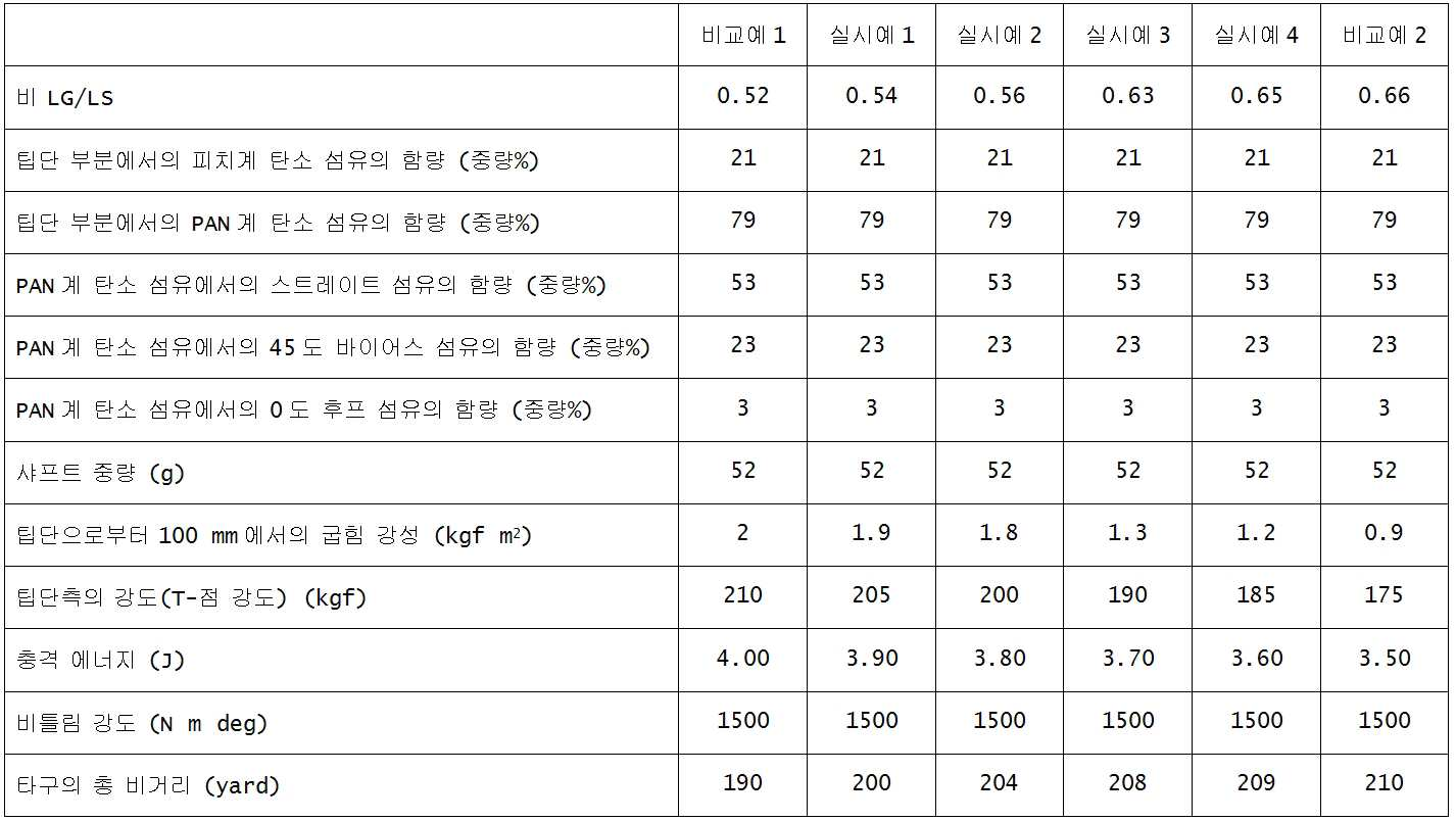
한편, 표 2에 나타내어진 바와 같이, 비교예 1은, 비(LG/LS)가 작기 때문에, 타구의 총 비거리가 향상될 수 없다. 한편, 비교예 2는, 팁단측을 얇게 세팅함으로써 샤프트가 갖는 비(LG/LS)가 크기 때문에, 클럽 샤프트의 팁단측의 강도를 향상시킬 수 없다.On the other hand, as shown in Table 2, in Comparative Example 1, since the ratio (LG / LS) is small, the total flying distance of the hitting ball cannot be improved. On the other hand, in Comparative Example 2, since the ratio (LG / LS) of the shaft is large by setting the tip end side thinly, the strength of the tip end side of the club shaft cannot be improved.
표 3에 나타내어진 바와 같이, 비교예 3은, 피치계 탄소 섬유의 함량이 적기 때문에, 충격 에너지에 대한 저항성이 향상될 수 없다. 비교예 4는, 피치계 탄소 섬유의 함량이 많기 때문에, 클럽 샤프트의 팁단측의 강도가 향상될 수 없다.As shown in Table 3, in Comparative Example 3, since the content of the pitch-based carbon fiber is small, the resistance to impact energy cannot be improved. In Comparative Example 4, since the content of the pitch-based carbon fibers is large, the strength of the tip end side of the club shaft cannot be improved.
표 4에 나타내어진 바와 같이, 비교예 5는, PAN계 탄소 섬유의 함량이 적기 때문에, 샤프트의 팁단측의 강도가 향상될 수 없다. 비교예 6은, 클럽 샤프트의 중량이 크기 때문에, 타구의 총 비거리가 향상될 수 없다.As shown in Table 4, in Comparative Example 5, since the content of the PAN-based carbon fiber is small, the strength at the tip end side of the shaft cannot be improved. In Comparative Example 6, because the weight of the club shaft is large, the total flying distance of the hitting ball cannot be improved.
표 5에 나타내어진 바와 같이, 실시예 13은, PAN계 탄소 섬유에 있어서 스트레이트 섬유의 함량이 적기 때문에, 팁단 부분의 강도를 저하시킬 수 있다. 비교예 7은, PAN계 탄소 섬유에 있어서 스트레이트 섬유의 함량이 많기 때문에, 타구의 총 비거리가 향상될 수 없다.As shown in Table 5, in Example 13, since the content of the straight fiber is small in the PAN-based carbon fiber, the strength of the tip end portion can be reduced. In Comparative Example 7, since the content of the straight fibers is large in the PAN-based carbon fiber, the total flying distance of the batting cannot be improved.
표 6에 나타내어진 바와 같이, 실시예 18은, PAN계 탄소 섬유에 있어서 바이어스 섬유의 함량이 적기 때문에, 샤프트의 비틀림 강도를 저하시킬 수 있고, 실시예 19는, PAN계 탄소 섬유에 있어서 바이어스 섬유의 함량이 많기 때문에, 팁단 부분의 강도를 저하시킬 수 있다.As shown in Table 6, in Example 18, since the content of the bias fiber is small in the PAN-based carbon fiber, the torsional strength of the shaft can be reduced, and in Example 19, the bias fiber in the PAN-based carbon fiber Since the content of is large, the strength of the tip end portion can be reduced.
Claims (10)
중량이 30 g 내지 55 g의 범위이며,
상기 팁단과 상기 버트단 사이의 전체 길이를 LS라 하고, 상기 팁단으로부터 샤프트의 무게 중심까지의 거리를 LG라 할 때, 전체 길이(LS)에 대한 거리(LG)의 비(LG/LS)가 0.54 내지 0.65의 범위이며,
상기 팁단으로부터 상기 버트단측으로 300 ㎜의 길이를 갖는 팁단 부분에 포함되는 섬유에는, 피치계 탄소 섬유 및 PAN계 탄소 섬유가 포함되고,
상기 팁단 부분의 섬유는, 15 중량% 내지 25 중량%의 상기 피치계 탄소 섬유와, 85 중량% 내지 75 중량%의 상기 PAN계 탄소 섬유를 포함하는 것인 골프 클럽 샤프트.A golf club shaft extending from the tip end to the butt end and made of fiber reinforced resin,
The weight ranges from 30 g to 55 g,
When the total length between the tip end and the butt end is LS and the distance from the tip end to the center of gravity of the shaft is LG, the ratio LG / LS of the distance LG to the total length LS is In the range of 0.54 to 0.65,
The fiber included in the tip end portion having a length of 300 mm from the tip end to the butt end side includes pitch-based carbon fibers and PAN-based carbon fibers,
Wherein the fiber of the tip end portion comprises 15 wt% to 25 wt% of the pitch-based carbon fiber and 85 wt% to 75 wt% of the PAN-based carbon fiber.
상기 스트레이트 섬유는, 팁단 부분의 전체 섬유 중에 50 중량% 내지 80 중량%의 범위로 함유되는 것인 골프 클럽 샤프트.The PAN-based carbon fiber of the tip end portion comprises a straight fiber parallel to the axial direction of the shaft,
Wherein the straight fibers are contained in the range of 50% to 80% by weight in the total fiber of the tip end portion.
상기 팁단 부분의 바이어스 섬유는, 팁단 부분의 전체 섬유 중에 5 중량% 내지 25 중량%의 범위로 함유되는 것인 골프 클럽 샤프트.According to claim 1 or 2, wherein the PAN-based carbon fiber of the tip end portion, comprising a bias fiber inclined at an angle of 45 degrees ± 5 degrees with respect to the axial direction of the shaft,
And the bias fiber of the tip end portion is contained in the range of 5% to 25% by weight in the total fiber of the tip end portion.
Applications Claiming Priority (2)
| Application Number | Priority Date | Filing Date | Title |
|---|---|---|---|
| JP2011224798A JP5181055B1 (en) | 2011-10-12 | 2011-10-12 | Golf club shaft and golf club |
| JPJP-P-2011-224798 | 2011-10-12 |
Publications (2)
| Publication Number | Publication Date |
|---|---|
| KR20130039711A true KR20130039711A (en) | 2013-04-22 |
| KR101917886B1 KR101917886B1 (en) | 2018-11-12 |
Family
ID=48054560
Family Applications (1)
| Application Number | Title | Priority Date | Filing Date |
|---|---|---|---|
| KR1020120113761A KR101917886B1 (en) | 2011-10-12 | 2012-10-12 | Golf club shaft and golf club using the same |
Country Status (4)
| Country | Link |
|---|---|
| US (1) | US8777772B2 (en) |
| JP (1) | JP5181055B1 (en) |
| KR (1) | KR101917886B1 (en) |
| CN (1) | CN103041558B (en) |
Families Citing this family (11)
| Publication number | Priority date | Publication date | Assignee | Title |
|---|---|---|---|---|
| JP5961406B2 (en) * | 2012-02-29 | 2016-08-02 | ダンロップスポーツ株式会社 | Golf club shaft |
| EP3075420B1 (en) | 2012-05-29 | 2018-07-25 | Mitsubishi Chemical Corporation | Golf club shaft for wood club |
| JP5546701B1 (en) * | 2013-07-22 | 2014-07-09 | ダンロップスポーツ株式会社 | Golf club |
| WO2015083277A1 (en) * | 2013-12-06 | 2015-06-11 | 藤倉ゴム工業株式会社 | Golf club shaft and golf club using same |
| WO2015105021A1 (en) * | 2014-01-08 | 2015-07-16 | 三菱レイヨン株式会社 | Golf club shaft and golf club |
| JP6316127B2 (en) * | 2014-07-15 | 2018-04-25 | 住友ゴム工業株式会社 | Golf club shaft |
| JP6729075B2 (en) * | 2016-06-30 | 2020-07-22 | 住友ゴム工業株式会社 | Golf club |
| WO2018081723A1 (en) | 2016-10-28 | 2018-05-03 | Karsten Manufacturing Corporation | Diameter profiled golf club shaft to reduce drag |
| US10857433B2 (en) * | 2018-01-31 | 2020-12-08 | Breakthrough Golf Technology, Llc | Golf shaft system and golf shaft |
| US10213666B1 (en) | 2018-01-31 | 2019-02-26 | Breakthrough Golf Technology Llc | Golf shaft |
| CN114867534B (en) * | 2019-12-19 | 2023-08-22 | 突破高尔夫技术有限责任公司 | Golf club body system and golf club body |
Family Cites Families (9)
| Publication number | Priority date | Publication date | Assignee | Title |
|---|---|---|---|---|
| IT1279371B1 (en) * | 1993-09-03 | 1997-12-10 | Shimano Kk | TUBULAR ELEMENT INCLUDING THE WINDING OF A PLURALITY OF LAYERS OF PRE-IMPREGNATED MATERIAL FOR USE FOR EXAMPLE AS A BARREL |
| US5968621A (en) * | 1996-01-16 | 1999-10-19 | Shimano, Inc. | Tubular member |
| JP2003000779A (en) * | 2001-06-19 | 2003-01-07 | Graphite Design Inc | Golf club shaft |
| JP2004201911A (en) | 2002-12-25 | 2004-07-22 | Yamaha Corp | Golf club |
| EP1729859A1 (en) * | 2004-02-18 | 2006-12-13 | Aldila, Inc. | Method for producing golf shafts of like flex |
| US7166038B2 (en) * | 2005-01-03 | 2007-01-23 | Callaway Golf Company | Golf club head |
| JP2008200116A (en) * | 2007-02-16 | 2008-09-04 | Sri Sports Ltd | Shaft for iron type golf club and iron type golf club |
| US20110224330A1 (en) * | 2008-06-26 | 2011-09-15 | Sodano Henry A | Fibers coated with nanowires for reinforcing composites |
| JP4886818B2 (en) | 2009-06-12 | 2012-02-29 | Sriスポーツ株式会社 | Golf club shaft and golf club |
-
2011
- 2011-10-12 JP JP2011224798A patent/JP5181055B1/en active Active
-
2012
- 2012-10-04 US US13/644,843 patent/US8777772B2/en active Active
- 2012-10-12 KR KR1020120113761A patent/KR101917886B1/en active IP Right Grant
- 2012-10-12 CN CN201210388408.1A patent/CN103041558B/en not_active Expired - Fee Related
Also Published As
| Publication number | Publication date |
|---|---|
| KR101917886B1 (en) | 2018-11-12 |
| US20130095949A1 (en) | 2013-04-18 |
| US8777772B2 (en) | 2014-07-15 |
| JP5181055B1 (en) | 2013-04-10 |
| CN103041558A (en) | 2013-04-17 |
| JP2013081693A (en) | 2013-05-09 |
| CN103041558B (en) | 2016-08-24 |
Similar Documents
| Publication | Publication Date | Title |
|---|---|---|
| KR20130039711A (en) | Golf club shaft and golf club using the same | |
| KR101331309B1 (en) | Golf club | |
| US10556162B2 (en) | Golf club | |
| KR101333353B1 (en) | Golf club | |
| KR101420507B1 (en) | Wood-type golf club | |
| KR101331300B1 (en) | Golf club | |
| JP5191563B1 (en) | Golf club shaft | |
| US8876628B2 (en) | Golf club shaft and golf club using the same | |
| JP5961406B2 (en) | Golf club shaft | |
| KR101331327B1 (en) | Golf club | |
| KR101460406B1 (en) | Golf club shaft | |
| JP2016185354A (en) | Golf Club Shaft | |
| JP5244255B2 (en) | Golf club shaft and golf club | |
| JP5244254B2 (en) | Golf club shaft and golf club |
Legal Events
| Date | Code | Title | Description |
|---|---|---|---|
| A201 | Request for examination | ||
| N231 | Notification of change of applicant | ||
| E701 | Decision to grant or registration of patent right | ||
| GRNT | Written decision to grant |