KR20130014564A - Filter systems including patterned optical analyte sensors and optical readers - Google Patents
Filter systems including patterned optical analyte sensors and optical readers Download PDFInfo
- Publication number
- KR20130014564A KR20130014564A KR1020127028363A KR20127028363A KR20130014564A KR 20130014564 A KR20130014564 A KR 20130014564A KR 1020127028363 A KR1020127028363 A KR 1020127028363A KR 20127028363 A KR20127028363 A KR 20127028363A KR 20130014564 A KR20130014564 A KR 20130014564A
- Authority
- KR
- South Korea
- Prior art keywords
- optical
- detector
- light source
- housing
- analyte sensor
- Prior art date
Links
- 230000003287 optical effect Effects 0.000 title claims abstract description 311
- 239000012491 analyte Substances 0.000 title claims abstract description 211
- 238000001514 detection method Methods 0.000 claims abstract description 70
- 230000004044 response Effects 0.000 claims abstract description 46
- 238000004891 communication Methods 0.000 claims abstract description 15
- 239000012530 fluid Substances 0.000 claims abstract description 15
- 230000003595 spectral effect Effects 0.000 claims description 30
- 230000001747 exhibiting effect Effects 0.000 claims description 8
- 239000010410 layer Substances 0.000 description 85
- 230000008859 change Effects 0.000 description 38
- 239000000463 material Substances 0.000 description 32
- 239000000758 substrate Substances 0.000 description 26
- 239000002250 absorbent Substances 0.000 description 22
- 230000002745 absorbent Effects 0.000 description 22
- OKTJSMMVPCPJKN-UHFFFAOYSA-N Carbon Chemical compound [C] OKTJSMMVPCPJKN-UHFFFAOYSA-N 0.000 description 17
- 238000000034 method Methods 0.000 description 16
- 239000003570 air Substances 0.000 description 14
- 239000000178 monomer Substances 0.000 description 14
- 238000001228 spectrum Methods 0.000 description 14
- VYPSYNLAJGMNEJ-UHFFFAOYSA-N Silicium dioxide Chemical compound O=[Si]=O VYPSYNLAJGMNEJ-UHFFFAOYSA-N 0.000 description 13
- 230000013011 mating Effects 0.000 description 13
- 239000000203 mixture Substances 0.000 description 13
- 238000001179 sorption measurement Methods 0.000 description 13
- 239000007789 gas Substances 0.000 description 12
- 229920000642 polymer Polymers 0.000 description 12
- 239000010408 film Substances 0.000 description 11
- 239000000853 adhesive Substances 0.000 description 10
- 230000001070 adhesive effect Effects 0.000 description 10
- 230000007246 mechanism Effects 0.000 description 9
- 239000000126 substance Substances 0.000 description 9
- 230000006870 function Effects 0.000 description 8
- 239000002245 particle Substances 0.000 description 8
- 239000011148 porous material Substances 0.000 description 7
- QTBSBXVTEAMEQO-UHFFFAOYSA-N Acetic acid Chemical compound CC(O)=O QTBSBXVTEAMEQO-UHFFFAOYSA-N 0.000 description 6
- UHOVQNZJYSORNB-UHFFFAOYSA-N Benzene Chemical compound C1=CC=CC=C1 UHOVQNZJYSORNB-UHFFFAOYSA-N 0.000 description 6
- OKKJLVBELUTLKV-UHFFFAOYSA-N Methanol Chemical compound OC OKKJLVBELUTLKV-UHFFFAOYSA-N 0.000 description 6
- YXFVVABEGXRONW-UHFFFAOYSA-N Toluene Chemical compound CC1=CC=CC=C1 YXFVVABEGXRONW-UHFFFAOYSA-N 0.000 description 6
- 229910052751 metal Inorganic materials 0.000 description 6
- 239000002184 metal Substances 0.000 description 6
- 230000036961 partial effect Effects 0.000 description 6
- 239000000377 silicon dioxide Substances 0.000 description 6
- 239000007787 solid Substances 0.000 description 6
- 238000011282 treatment Methods 0.000 description 6
- 230000000007 visual effect Effects 0.000 description 6
- PXHVJJICTQNCMI-UHFFFAOYSA-N Nickel Chemical compound [Ni] PXHVJJICTQNCMI-UHFFFAOYSA-N 0.000 description 5
- BQCADISMDOOEFD-UHFFFAOYSA-N Silver Chemical compound [Ag] BQCADISMDOOEFD-UHFFFAOYSA-N 0.000 description 5
- 230000005540 biological transmission Effects 0.000 description 5
- 238000000151 deposition Methods 0.000 description 5
- 238000013461 design Methods 0.000 description 5
- 239000002105 nanoparticle Substances 0.000 description 5
- 229920003023 plastic Polymers 0.000 description 5
- 238000012545 processing Methods 0.000 description 5
- 230000001681 protective effect Effects 0.000 description 5
- 230000029058 respiratory gaseous exchange Effects 0.000 description 5
- 238000002834 transmittance Methods 0.000 description 5
- -1 C1 2 Inorganic materials 0.000 description 4
- 239000004820 Pressure-sensitive adhesive Substances 0.000 description 4
- PPBRXRYQALVLMV-UHFFFAOYSA-N Styrene Chemical compound C=CC1=CC=CC=C1 PPBRXRYQALVLMV-UHFFFAOYSA-N 0.000 description 4
- WYURNTSHIVDZCO-UHFFFAOYSA-N Tetrahydrofuran Chemical compound C1CCOC1 WYURNTSHIVDZCO-UHFFFAOYSA-N 0.000 description 4
- RTAQQCXQSZGOHL-UHFFFAOYSA-N Titanium Chemical compound [Ti] RTAQQCXQSZGOHL-UHFFFAOYSA-N 0.000 description 4
- 230000008901 benefit Effects 0.000 description 4
- 239000000356 contaminant Substances 0.000 description 4
- 229910052709 silver Inorganic materials 0.000 description 4
- 239000004332 silver Substances 0.000 description 4
- 229910052719 titanium Inorganic materials 0.000 description 4
- 239000010936 titanium Substances 0.000 description 4
- 239000010457 zeolite Substances 0.000 description 4
- ZWEHNKRNPOVVGH-UHFFFAOYSA-N 2-Butanone Chemical compound CCC(C)=O ZWEHNKRNPOVVGH-UHFFFAOYSA-N 0.000 description 3
- CSCPPACGZOOCGX-UHFFFAOYSA-N Acetone Chemical compound CC(C)=O CSCPPACGZOOCGX-UHFFFAOYSA-N 0.000 description 3
- WEVYAHXRMPXWCK-UHFFFAOYSA-N Acetonitrile Chemical compound CC#N WEVYAHXRMPXWCK-UHFFFAOYSA-N 0.000 description 3
- 238000012935 Averaging Methods 0.000 description 3
- LFQSCWFLJHTTHZ-UHFFFAOYSA-N Ethanol Chemical compound CCO LFQSCWFLJHTTHZ-UHFFFAOYSA-N 0.000 description 3
- XEKOWRVHYACXOJ-UHFFFAOYSA-N Ethyl acetate Chemical compound CCOC(C)=O XEKOWRVHYACXOJ-UHFFFAOYSA-N 0.000 description 3
- WSFSSNUMVMOOMR-UHFFFAOYSA-N Formaldehyde Chemical compound O=C WSFSSNUMVMOOMR-UHFFFAOYSA-N 0.000 description 3
- KFZMGEQAYNKOFK-UHFFFAOYSA-N Isopropanol Chemical compound CC(C)O KFZMGEQAYNKOFK-UHFFFAOYSA-N 0.000 description 3
- LRHPLDYGYMQRHN-UHFFFAOYSA-N N-Butanol Chemical compound CCCCO LRHPLDYGYMQRHN-UHFFFAOYSA-N 0.000 description 3
- XUIMIQQOPSSXEZ-UHFFFAOYSA-N Silicon Chemical compound [Si] XUIMIQQOPSSXEZ-UHFFFAOYSA-N 0.000 description 3
- HEMHJVSKTPXQMS-UHFFFAOYSA-M Sodium hydroxide Chemical compound [OH-].[Na+] HEMHJVSKTPXQMS-UHFFFAOYSA-M 0.000 description 3
- 239000012080 ambient air Substances 0.000 description 3
- 229910052799 carbon Inorganic materials 0.000 description 3
- 238000004132 cross linking Methods 0.000 description 3
- 238000010586 diagram Methods 0.000 description 3
- 239000006260 foam Substances 0.000 description 3
- 230000002209 hydrophobic effect Effects 0.000 description 3
- 230000000873 masking effect Effects 0.000 description 3
- 239000002082 metal nanoparticle Substances 0.000 description 3
- 229910044991 metal oxide Inorganic materials 0.000 description 3
- 150000004706 metal oxides Chemical class 0.000 description 3
- 238000012544 monitoring process Methods 0.000 description 3
- 229920000139 polyethylene terephthalate Polymers 0.000 description 3
- 239000005020 polyethylene terephthalate Substances 0.000 description 3
- 239000013316 polymer of intrinsic microporosity Substances 0.000 description 3
- 239000011347 resin Substances 0.000 description 3
- 229920005989 resin Polymers 0.000 description 3
- 230000035945 sensitivity Effects 0.000 description 3
- 229910052710 silicon Inorganic materials 0.000 description 3
- 239000010703 silicon Substances 0.000 description 3
- 238000012360 testing method Methods 0.000 description 3
- 238000012546 transfer Methods 0.000 description 3
- 238000011144 upstream manufacturing Methods 0.000 description 3
- 239000012855 volatile organic compound Substances 0.000 description 3
- XLYOFNOQVPJJNP-UHFFFAOYSA-N water Chemical compound O XLYOFNOQVPJJNP-UHFFFAOYSA-N 0.000 description 3
- ARXJGSRGQADJSQ-UHFFFAOYSA-N 1-methoxypropan-2-ol Chemical compound COCC(C)O ARXJGSRGQADJSQ-UHFFFAOYSA-N 0.000 description 2
- ICSNLGPSRYBMBD-UHFFFAOYSA-N 2-aminopyridine Chemical compound NC1=CC=CC=N1 ICSNLGPSRYBMBD-UHFFFAOYSA-N 0.000 description 2
- QGZKDVFQNNGYKY-UHFFFAOYSA-N Ammonia Chemical compound N QGZKDVFQNNGYKY-UHFFFAOYSA-N 0.000 description 2
- IJGRMHOSHXDMSA-UHFFFAOYSA-N Atomic nitrogen Chemical compound N#N IJGRMHOSHXDMSA-UHFFFAOYSA-N 0.000 description 2
- CURLTUGMZLYLDI-UHFFFAOYSA-N Carbon dioxide Chemical compound O=C=O CURLTUGMZLYLDI-UHFFFAOYSA-N 0.000 description 2
- 206010011906 Death Diseases 0.000 description 2
- BAVYZALUXZFZLV-UHFFFAOYSA-N Methylamine Chemical compound NC BAVYZALUXZFZLV-UHFFFAOYSA-N 0.000 description 2
- KDLHZDBZIXYQEI-UHFFFAOYSA-N Palladium Chemical compound [Pd] KDLHZDBZIXYQEI-UHFFFAOYSA-N 0.000 description 2
- 229920002367 Polyisobutene Polymers 0.000 description 2
- DKGAVHZHDRPRBM-UHFFFAOYSA-N Tert-Butanol Chemical compound CC(C)(C)O DKGAVHZHDRPRBM-UHFFFAOYSA-N 0.000 description 2
- GWEVSGVZZGPLCZ-UHFFFAOYSA-N Titan oxide Chemical compound O=[Ti]=O GWEVSGVZZGPLCZ-UHFFFAOYSA-N 0.000 description 2
- NIXOWILDQLNWCW-UHFFFAOYSA-N acrylic acid group Chemical group C(C=C)(=O)O NIXOWILDQLNWCW-UHFFFAOYSA-N 0.000 description 2
- 239000003463 adsorbent Substances 0.000 description 2
- 230000000274 adsorptive effect Effects 0.000 description 2
- 150000001335 aliphatic alkanes Chemical class 0.000 description 2
- PNEYBMLMFCGWSK-UHFFFAOYSA-N aluminium oxide Inorganic materials [O-2].[O-2].[O-2].[Al+3].[Al+3] PNEYBMLMFCGWSK-UHFFFAOYSA-N 0.000 description 2
- 150000001412 amines Chemical class 0.000 description 2
- 239000012298 atmosphere Substances 0.000 description 2
- 230000004397 blinking Effects 0.000 description 2
- 229920001400 block copolymer Polymers 0.000 description 2
- MVPPADPHJFYWMZ-UHFFFAOYSA-N chlorobenzene Chemical compound ClC1=CC=CC=C1 MVPPADPHJFYWMZ-UHFFFAOYSA-N 0.000 description 2
- 238000000576 coating method Methods 0.000 description 2
- 239000003086 colorant Substances 0.000 description 2
- 239000000428 dust Substances 0.000 description 2
- 230000000694 effects Effects 0.000 description 2
- 239000011521 glass Substances 0.000 description 2
- 229910052739 hydrogen Inorganic materials 0.000 description 2
- 238000005286 illumination Methods 0.000 description 2
- 229910010272 inorganic material Inorganic materials 0.000 description 2
- 239000011147 inorganic material Substances 0.000 description 2
- 238000005259 measurement Methods 0.000 description 2
- 150000002739 metals Chemical class 0.000 description 2
- 239000012229 microporous material Substances 0.000 description 2
- 229910052759 nickel Inorganic materials 0.000 description 2
- TVMXDCGIABBOFY-UHFFFAOYSA-N octane Chemical compound CCCCCCCC TVMXDCGIABBOFY-UHFFFAOYSA-N 0.000 description 2
- 239000012788 optical film Substances 0.000 description 2
- TWNQGVIAIRXVLR-UHFFFAOYSA-N oxo(oxoalumanyloxy)alumane Chemical compound O=[Al]O[Al]=O TWNQGVIAIRXVLR-UHFFFAOYSA-N 0.000 description 2
- 230000000737 periodic effect Effects 0.000 description 2
- 239000004033 plastic Substances 0.000 description 2
- BASFCYQUMIYNBI-UHFFFAOYSA-N platinum Chemical compound [Pt] BASFCYQUMIYNBI-UHFFFAOYSA-N 0.000 description 2
- 239000004417 polycarbonate Substances 0.000 description 2
- 229920000515 polycarbonate Polymers 0.000 description 2
- 239000003361 porogen Substances 0.000 description 2
- BWHMMNNQKKPAPP-UHFFFAOYSA-L potassium carbonate Chemical compound [K+].[K+].[O-]C([O-])=O BWHMMNNQKKPAPP-UHFFFAOYSA-L 0.000 description 2
- 230000008569 process Effects 0.000 description 2
- 238000000926 separation method Methods 0.000 description 2
- 239000000243 solution Substances 0.000 description 2
- 239000002594 sorbent Substances 0.000 description 2
- 239000004094 surface-active agent Substances 0.000 description 2
- VZGDMQKNWNREIO-UHFFFAOYSA-N tetrachloromethane Chemical compound ClC(Cl)(Cl)Cl VZGDMQKNWNREIO-UHFFFAOYSA-N 0.000 description 2
- 239000010409 thin film Substances 0.000 description 2
- 230000036962 time dependent Effects 0.000 description 2
- OGIDPMRJRNCKJF-UHFFFAOYSA-N titanium oxide Inorganic materials [Ti]=O OGIDPMRJRNCKJF-UHFFFAOYSA-N 0.000 description 2
- 238000001429 visible spectrum Methods 0.000 description 2
- UOCLXMDMGBRAIB-UHFFFAOYSA-N 1,1,1-trichloroethane Chemical compound CC(Cl)(Cl)Cl UOCLXMDMGBRAIB-UHFFFAOYSA-N 0.000 description 1
- XNWFRZJHXBZDAG-UHFFFAOYSA-N 2-METHOXYETHANOL Chemical compound COCCO XNWFRZJHXBZDAG-UHFFFAOYSA-N 0.000 description 1
- ZNQVEEAIQZEUHB-UHFFFAOYSA-N 2-ethoxyethanol Chemical compound CCOCCO ZNQVEEAIQZEUHB-UHFFFAOYSA-N 0.000 description 1
- 229940093475 2-ethoxyethanol Drugs 0.000 description 1
- 239000004215 Carbon black (E152) Substances 0.000 description 1
- VYZAMTAEIAYCRO-UHFFFAOYSA-N Chromium Chemical compound [Cr] VYZAMTAEIAYCRO-UHFFFAOYSA-N 0.000 description 1
- XDTMQSROBMDMFD-UHFFFAOYSA-N Cyclohexane Chemical compound C1CCCCC1 XDTMQSROBMDMFD-UHFFFAOYSA-N 0.000 description 1
- WQZGKKKJIJFFOK-QTVWNMPRSA-N D-mannopyranose Chemical compound OC[C@H]1OC(O)[C@@H](O)[C@@H](O)[C@@H]1O WQZGKKKJIJFFOK-QTVWNMPRSA-N 0.000 description 1
- 239000004593 Epoxy Substances 0.000 description 1
- WQZGKKKJIJFFOK-GASJEMHNSA-N Glucose Natural products OC[C@H]1OC(O)[C@H](O)[C@@H](O)[C@@H]1O WQZGKKKJIJFFOK-GASJEMHNSA-N 0.000 description 1
- 229920000134 Metallised film Polymers 0.000 description 1
- 239000004677 Nylon Substances 0.000 description 1
- CTQNGGLPUBDAKN-UHFFFAOYSA-N O-Xylene Chemical compound CC1=CC=CC=C1C CTQNGGLPUBDAKN-UHFFFAOYSA-N 0.000 description 1
- BPQQTUXANYXVAA-UHFFFAOYSA-N Orthosilicate Chemical compound [O-][Si]([O-])([O-])[O-] BPQQTUXANYXVAA-UHFFFAOYSA-N 0.000 description 1
- 239000004793 Polystyrene Substances 0.000 description 1
- 229910052581 Si3N4 Inorganic materials 0.000 description 1
- BLRPTPMANUNPDV-UHFFFAOYSA-N Silane Chemical compound [SiH4] BLRPTPMANUNPDV-UHFFFAOYSA-N 0.000 description 1
- FOIXSVOLVBLSDH-UHFFFAOYSA-N Silver ion Chemical compound [Ag+] FOIXSVOLVBLSDH-UHFFFAOYSA-N 0.000 description 1
- NRTOMJZYCJJWKI-UHFFFAOYSA-N Titanium nitride Chemical compound [Ti]#N NRTOMJZYCJJWKI-UHFFFAOYSA-N 0.000 description 1
- WGLPBDUCMAPZCE-UHFFFAOYSA-N Trioxochromium Chemical compound O=[Cr](=O)=O WGLPBDUCMAPZCE-UHFFFAOYSA-N 0.000 description 1
- 229910021536 Zeolite Inorganic materials 0.000 description 1
- 239000011358 absorbing material Substances 0.000 description 1
- 238000010521 absorption reaction Methods 0.000 description 1
- 239000002253 acid Substances 0.000 description 1
- 239000003929 acidic solution Substances 0.000 description 1
- 150000003926 acrylamides Chemical class 0.000 description 1
- 150000001252 acrylic acid derivatives Chemical class 0.000 description 1
- 239000012790 adhesive layer Substances 0.000 description 1
- 239000002390 adhesive tape Substances 0.000 description 1
- 150000001298 alcohols Chemical class 0.000 description 1
- 239000012670 alkaline solution Substances 0.000 description 1
- 150000001336 alkenes Chemical class 0.000 description 1
- 125000005211 alkyl trimethyl ammonium group Chemical group 0.000 description 1
- 229910045601 alloy Inorganic materials 0.000 description 1
- 239000000956 alloy Substances 0.000 description 1
- 229910052782 aluminium Inorganic materials 0.000 description 1
- XAGFODPZIPBFFR-UHFFFAOYSA-N aluminium Chemical compound [Al] XAGFODPZIPBFFR-UHFFFAOYSA-N 0.000 description 1
- 229910021529 ammonia Inorganic materials 0.000 description 1
- 150000008064 anhydrides Chemical class 0.000 description 1
- 125000000129 anionic group Chemical group 0.000 description 1
- 239000003945 anionic surfactant Substances 0.000 description 1
- 230000003667 anti-reflective effect Effects 0.000 description 1
- 150000001491 aromatic compounds Chemical class 0.000 description 1
- 230000004888 barrier function Effects 0.000 description 1
- 239000011324 bead Substances 0.000 description 1
- WQZGKKKJIJFFOK-VFUOTHLCSA-N beta-D-glucose Chemical compound OC[C@H]1O[C@@H](O)[C@H](O)[C@@H](O)[C@@H]1O WQZGKKKJIJFFOK-VFUOTHLCSA-N 0.000 description 1
- 230000002902 bimodal effect Effects 0.000 description 1
- 239000011230 binding agent Substances 0.000 description 1
- 150000001722 carbon compounds Chemical class 0.000 description 1
- 239000001569 carbon dioxide Substances 0.000 description 1
- 229910002092 carbon dioxide Inorganic materials 0.000 description 1
- QGJOPFRUJISHPQ-NJFSPNSNSA-N carbon disulfide-14c Chemical compound S=[14C]=S QGJOPFRUJISHPQ-NJFSPNSNSA-N 0.000 description 1
- 238000005229 chemical vapour deposition Methods 0.000 description 1
- 229910052804 chromium Inorganic materials 0.000 description 1
- 239000011651 chromium Substances 0.000 description 1
- 229910000423 chromium oxide Inorganic materials 0.000 description 1
- 239000004927 clay Substances 0.000 description 1
- 239000011248 coating agent Substances 0.000 description 1
- 239000000084 colloidal system Substances 0.000 description 1
- 239000002131 composite material Substances 0.000 description 1
- 150000001875 compounds Chemical class 0.000 description 1
- 238000011109 contamination Methods 0.000 description 1
- 229920006037 cross link polymer Polymers 0.000 description 1
- 230000001186 cumulative effect Effects 0.000 description 1
- 150000001913 cyanates Chemical class 0.000 description 1
- QPJDMGCKMHUXFD-UHFFFAOYSA-N cyanogen chloride Chemical compound ClC#N QPJDMGCKMHUXFD-UHFFFAOYSA-N 0.000 description 1
- 150000001924 cycloalkanes Chemical class 0.000 description 1
- DIOQZVSQGTUSAI-NJFSPNSNSA-N decane Chemical compound CCCCCCCCC[14CH3] DIOQZVSQGTUSAI-NJFSPNSNSA-N 0.000 description 1
- 230000008021 deposition Effects 0.000 description 1
- 230000001066 destructive effect Effects 0.000 description 1
- 238000009792 diffusion process Methods 0.000 description 1
- HNPSIPDUKPIQMN-UHFFFAOYSA-N dioxosilane;oxo(oxoalumanyloxy)alumane Chemical compound O=[Si]=O.O=[Al]O[Al]=O HNPSIPDUKPIQMN-UHFFFAOYSA-N 0.000 description 1
- 230000008034 disappearance Effects 0.000 description 1
- 239000013013 elastic material Substances 0.000 description 1
- 238000010894 electron beam technology Methods 0.000 description 1
- 238000000295 emission spectrum Methods 0.000 description 1
- 239000000839 emulsion Substances 0.000 description 1
- 230000007613 environmental effect Effects 0.000 description 1
- 150000002148 esters Chemical class 0.000 description 1
- 238000005530 etching Methods 0.000 description 1
- 150000002170 ethers Chemical class 0.000 description 1
- 238000005187 foaming Methods 0.000 description 1
- 230000005251 gamma ray Effects 0.000 description 1
- 239000008103 glucose Substances 0.000 description 1
- PCHJSUWPFVWCPO-UHFFFAOYSA-N gold Chemical compound [Au] PCHJSUWPFVWCPO-UHFFFAOYSA-N 0.000 description 1
- 229910052737 gold Inorganic materials 0.000 description 1
- 239000010931 gold Substances 0.000 description 1
- 150000008282 halocarbons Chemical class 0.000 description 1
- 231100001261 hazardous Toxicity 0.000 description 1
- 238000010438 heat treatment Methods 0.000 description 1
- 239000012943 hotmelt Substances 0.000 description 1
- 229930195733 hydrocarbon Natural products 0.000 description 1
- 150000002430 hydrocarbons Chemical class 0.000 description 1
- 239000001257 hydrogen Substances 0.000 description 1
- 238000010348 incorporation Methods 0.000 description 1
- 239000000976 ink Substances 0.000 description 1
- 229910052500 inorganic mineral Inorganic materials 0.000 description 1
- 150000008040 ionic compounds Chemical class 0.000 description 1
- 230000001678 irradiating effect Effects 0.000 description 1
- 150000002576 ketones Chemical class 0.000 description 1
- 238000000608 laser ablation Methods 0.000 description 1
- 230000000670 limiting effect Effects 0.000 description 1
- 239000007788 liquid Substances 0.000 description 1
- 231100000053 low toxicity Toxicity 0.000 description 1
- 229920002521 macromolecule Polymers 0.000 description 1
- 238000004519 manufacturing process Methods 0.000 description 1
- 239000011159 matrix material Substances 0.000 description 1
- 150000002734 metacrylic acid derivatives Chemical class 0.000 description 1
- 239000011707 mineral Substances 0.000 description 1
- 239000003595 mist Substances 0.000 description 1
- 239000002808 molecular sieve Substances 0.000 description 1
- DIOQZVSQGTUSAI-UHFFFAOYSA-N n-butylhexane Natural products CCCCCCCCCC DIOQZVSQGTUSAI-UHFFFAOYSA-N 0.000 description 1
- 150000002823 nitrates Chemical class 0.000 description 1
- 150000004767 nitrides Chemical class 0.000 description 1
- 150000002825 nitriles Chemical class 0.000 description 1
- 229910052757 nitrogen Inorganic materials 0.000 description 1
- LYGJENNIWJXYER-UHFFFAOYSA-N nitromethane Chemical compound C[N+]([O-])=O LYGJENNIWJXYER-UHFFFAOYSA-N 0.000 description 1
- 239000002736 nonionic surfactant Substances 0.000 description 1
- 229920001778 nylon Polymers 0.000 description 1
- 230000005693 optoelectronics Effects 0.000 description 1
- 150000007524 organic acids Chemical class 0.000 description 1
- 235000005985 organic acids Nutrition 0.000 description 1
- 239000003960 organic solvent Substances 0.000 description 1
- RVTZCBVAJQQJTK-UHFFFAOYSA-N oxygen(2-);zirconium(4+) Chemical compound [O-2].[O-2].[Zr+4] RVTZCBVAJQQJTK-UHFFFAOYSA-N 0.000 description 1
- 239000003973 paint Substances 0.000 description 1
- 229910052763 palladium Inorganic materials 0.000 description 1
- 230000035515 penetration Effects 0.000 description 1
- 230000035699 permeability Effects 0.000 description 1
- 230000000704 physical effect Effects 0.000 description 1
- 238000001020 plasma etching Methods 0.000 description 1
- 239000002985 plastic film Substances 0.000 description 1
- 229920006255 plastic film Polymers 0.000 description 1
- 229910052697 platinum Inorganic materials 0.000 description 1
- 229920002959 polymer blend Polymers 0.000 description 1
- 229920002223 polystyrene Polymers 0.000 description 1
- 239000004810 polytetrafluoroethylene Substances 0.000 description 1
- 229920001343 polytetrafluoroethylene Polymers 0.000 description 1
- 229910000027 potassium carbonate Inorganic materials 0.000 description 1
- 239000000843 powder Substances 0.000 description 1
- 239000002243 precursor Substances 0.000 description 1
- 230000000750 progressive effect Effects 0.000 description 1
- 238000012797 qualification Methods 0.000 description 1
- 230000000241 respiratory effect Effects 0.000 description 1
- 230000025508 response to water Effects 0.000 description 1
- 230000000717 retained effect Effects 0.000 description 1
- 229910000077 silane Inorganic materials 0.000 description 1
- 150000004760 silicates Chemical class 0.000 description 1
- HQVNEWCFYHHQES-UHFFFAOYSA-N silicon nitride Chemical compound N12[Si]34N5[Si]62N3[Si]51N64 HQVNEWCFYHHQES-UHFFFAOYSA-N 0.000 description 1
- 229910052814 silicon oxide Inorganic materials 0.000 description 1
- 239000002356 single layer Substances 0.000 description 1
- URGAHOPLAPQHLN-UHFFFAOYSA-N sodium aluminosilicate Chemical compound [Na+].[Al+3].[O-][Si]([O-])=O.[O-][Si]([O-])=O URGAHOPLAPQHLN-UHFFFAOYSA-N 0.000 description 1
- 239000007921 spray Substances 0.000 description 1
- 235000000346 sugar Nutrition 0.000 description 1
- 150000008163 sugars Chemical class 0.000 description 1
- YLQBMQCUIZJEEH-UHFFFAOYSA-N tetrahydrofuran Natural products C=1C=COC=1 YLQBMQCUIZJEEH-UHFFFAOYSA-N 0.000 description 1
- XOLBLPGZBRYERU-UHFFFAOYSA-N tin dioxide Chemical compound O=[Sn]=O XOLBLPGZBRYERU-UHFFFAOYSA-N 0.000 description 1
- 229910001887 tin oxide Inorganic materials 0.000 description 1
- DVKJHBMWWAPEIU-UHFFFAOYSA-N toluene 2,4-diisocyanate Chemical compound CC1=CC=C(N=C=O)C=C1N=C=O DVKJHBMWWAPEIU-UHFFFAOYSA-N 0.000 description 1
- 231100000331 toxic Toxicity 0.000 description 1
- 230000002588 toxic effect Effects 0.000 description 1
- 238000007740 vapor deposition Methods 0.000 description 1
- 125000000391 vinyl group Chemical group [H]C([*])=C([H])[H] 0.000 description 1
- 229920002554 vinyl polymer Polymers 0.000 description 1
- 238000011179 visual inspection Methods 0.000 description 1
- 229920003169 water-soluble polymer Polymers 0.000 description 1
- 239000001993 wax Substances 0.000 description 1
- 238000003466 welding Methods 0.000 description 1
- 238000001039 wet etching Methods 0.000 description 1
- 239000008096 xylene Substances 0.000 description 1
- 229910001928 zirconium oxide Inorganic materials 0.000 description 1
Images


Classifications
-
- B—PERFORMING OPERATIONS; TRANSPORTING
- B01—PHYSICAL OR CHEMICAL PROCESSES OR APPARATUS IN GENERAL
- B01D—SEPARATION
- B01D46/00—Filters or filtering processes specially modified for separating dispersed particles from gases or vapours
- B01D46/0084—Filters or filtering processes specially modified for separating dispersed particles from gases or vapours provided with safety means
- B01D46/0086—Filter condition indicators
-
- A—HUMAN NECESSITIES
- A62—LIFE-SAVING; FIRE-FIGHTING
- A62B—DEVICES, APPARATUS OR METHODS FOR LIFE-SAVING
- A62B18/00—Breathing masks or helmets, e.g. affording protection against chemical agents or for use at high altitudes or incorporating a pump or compressor for reducing the inhalation effort
- A62B18/08—Component parts for gas-masks or gas-helmets, e.g. windows, straps, speech transmitters, signal-devices
- A62B18/088—Devices for indicating filter saturation
-
- A—HUMAN NECESSITIES
- A62—LIFE-SAVING; FIRE-FIGHTING
- A62B—DEVICES, APPARATUS OR METHODS FOR LIFE-SAVING
- A62B7/00—Respiratory apparatus
- A62B7/10—Respiratory apparatus with filter elements
-
- B—PERFORMING OPERATIONS; TRANSPORTING
- B01—PHYSICAL OR CHEMICAL PROCESSES OR APPARATUS IN GENERAL
- B01D—SEPARATION
- B01D35/00—Filtering devices having features not specifically covered by groups B01D24/00 - B01D33/00, or for applications not specifically covered by groups B01D24/00 - B01D33/00; Auxiliary devices for filtration; Filter housing constructions
- B01D35/14—Safety devices specially adapted for filtration; Devices for indicating clogging
- B01D35/143—Filter condition indicators
-
- G—PHYSICS
- G01—MEASURING; TESTING
- G01N—INVESTIGATING OR ANALYSING MATERIALS BY DETERMINING THEIR CHEMICAL OR PHYSICAL PROPERTIES
- G01N21/00—Investigating or analysing materials by the use of optical means, i.e. using sub-millimetre waves, infrared, visible or ultraviolet light
- G01N21/17—Systems in which incident light is modified in accordance with the properties of the material investigated
- G01N21/25—Colour; Spectral properties, i.e. comparison of effect of material on the light at two or more different wavelengths or wavelength bands
- G01N21/31—Investigating relative effect of material at wavelengths characteristic of specific elements or molecules, e.g. atomic absorption spectrometry
- G01N21/314—Investigating relative effect of material at wavelengths characteristic of specific elements or molecules, e.g. atomic absorption spectrometry with comparison of measurements at specific and non-specific wavelengths
- G01N21/3151—Investigating relative effect of material at wavelengths characteristic of specific elements or molecules, e.g. atomic absorption spectrometry with comparison of measurements at specific and non-specific wavelengths using two sources of radiation of different wavelengths
-
- G—PHYSICS
- G01—MEASURING; TESTING
- G01N—INVESTIGATING OR ANALYSING MATERIALS BY DETERMINING THEIR CHEMICAL OR PHYSICAL PROPERTIES
- G01N21/00—Investigating or analysing materials by the use of optical means, i.e. using sub-millimetre waves, infrared, visible or ultraviolet light
- G01N21/84—Systems specially adapted for particular applications
- G01N21/88—Investigating the presence of flaws or contamination
- G01N21/8806—Specially adapted optical and illumination features
-
- A—HUMAN NECESSITIES
- A62—LIFE-SAVING; FIRE-FIGHTING
- A62B—DEVICES, APPARATUS OR METHODS FOR LIFE-SAVING
- A62B23/00—Filters for breathing-protection purposes
- A62B23/02—Filters for breathing-protection purposes for respirators
-
- G—PHYSICS
- G01—MEASURING; TESTING
- G01N—INVESTIGATING OR ANALYSING MATERIALS BY DETERMINING THEIR CHEMICAL OR PHYSICAL PROPERTIES
- G01N21/00—Investigating or analysing materials by the use of optical means, i.e. using sub-millimetre waves, infrared, visible or ultraviolet light
- G01N21/75—Systems in which material is subjected to a chemical reaction, the progress or the result of the reaction being investigated
- G01N21/77—Systems in which material is subjected to a chemical reaction, the progress or the result of the reaction being investigated by observing the effect on a chemical indicator
- G01N21/78—Systems in which material is subjected to a chemical reaction, the progress or the result of the reaction being investigated by observing the effect on a chemical indicator producing a change of colour
- G01N21/783—Systems in which material is subjected to a chemical reaction, the progress or the result of the reaction being investigated by observing the effect on a chemical indicator producing a change of colour for analysing gases
Abstract
필터 시스템은, 하우징, 하우징 내에 배치된 필터 매체, 광학 분석물 센서, 및 광학 판독기를 포함한다. 광학 분석물 센서는 관심대상 분석물에 대해 제1 응답을 보이는 제1 영역 및 관심대상 분석물에 대해 제2의 상이한 응답을 보이는 제2 영역으로 특징지어진다. 광학 분석물 센서는 검출 매체를 포함하며 검출 매체가 필터 매체와 유체통신하도록 하우징 내에 배치된다. 광학 판독기는 적어도 하나의 광원 및 적어도 하나의 검출기를 포함한다.The filter system includes a housing, a filter medium disposed within the housing, an optical analyte sensor, and an optical reader. The optical analyte sensor is characterized by a first region that exhibits a first response to the analyte of interest and a second region that exhibits a second different response to the analyte of interest. The optical analyte sensor includes a detection medium and is disposed within the housing such that the detection medium is in fluid communication with the filter medium. The optical reader includes at least one light source and at least one detector.
Description
본 개시는, 필터 매체, 필터 매체와 유체 통신(fluid communication)하도록 배치된 패턴화된 광학 분석물 센서, 및 패턴화된 광학 분석물 센서를 조사(interrogating)하도록 구성 및 배치된 광학 판독기를 포함하는 필터 시스템에 관한 것이다.The present disclosure includes a filter medium, a patterned optical analyte sensor disposed in fluid communication with the filter medium, and an optical reader constructed and arranged to interrogate the patterned optical analyte sensor. It relates to a filter system.
필터 시스템은 증기 및 기타 해로운 공중 물질(airbone substances)이 존재할 때 일반적으로 사용된다. 예시적인 필터 시스템은 집단 방호(collective protection) 시스템, 일회용 개인용 호흡기(respirator), 재사용가능한 개인용 호흡기, 전동식 공기 정화 호흡기, 해즈맷 수트(haz-mat suit) 및 기타 보호 장치를 포함한다.Filter systems are commonly used in the presence of steam and other harmful airbone substances. Exemplary filter systems include collective protection systems, disposable personal respirators, reusable personal respirators, electric air purifying respirators, haz-mat suits and other protective devices.
보호 장치의 사용자에게 원치않는 물질의 존재를 경고하기 위하여 다양한 화학적, 광학적 또는 전자적 표시기(indicator)들이 제안되어왔다. 예를 들어, 사용 수명 종료 표시기(ESLI : end-of-service-life indicator)는 이러한 장치 내의 필터 요소가 포화에 근접하고 있거나 특정 물질에 대해 효과가 없을 수 있음을 경고할 수 있다.Various chemical, optical or electronic indicators have been proposed to warn the user of the protective device of the presence of unwanted substances. For example, an end-of-service-life indicator (ESLI) may warn that filter elements in such devices are approaching saturation or may not be effective for certain materials.
화학적 분석물, 특히 유기 화학적 분석물을 검출하는 능력은 환경 모니터링 등을 비롯한 많은 응용에서 중요하다. 화학적 분석물의 검출을 위해 사용되어온 몇몇 장치들은 예를 들어, 광학적, 중량적(gravimetric), 마이크로전자적, 기계적, 그리고 비색적(colorimetric)으로 발전되어왔다.The ability to detect chemical analytes, especially organic chemical analytes, is important in many applications, including environmental monitoring. Several devices that have been used for the detection of chemical analytes have been developed, for example, optically, gravimetrically, microelectronically, mechanically and colorimetrically.
일 예시적인 실시예에서, 본 개시는, 하우징, 하우징 내에 배치된 필터 매체, 광학 분석물 센서, 및 광학 판독기를 포함하는 필터 시스템에 관한 것이다. 광학 분석물 센서는 관심대상 분석물에 대해 제1 응답을 보이는 제1 영역 및 관심대상 분석물에 대해 제2의 상이한 응답을 보이는 제2 영역으로 특징지어진다. 광학 분석물 센서는 검출 매체를 포함하며, 검출 매체가 필터 매체와 유체 통신하도록 하우징 내에 배치된다. 광학 판독기는 적어도 하나의 광원 및 적어도 하나의 검출기를 포함한다.In one exemplary embodiment, the present disclosure relates to a filter system comprising a housing, a filter medium disposed within the housing, an optical analyte sensor, and an optical reader. The optical analyte sensor is characterized by a first region that exhibits a first response to the analyte of interest and a second region that exhibits a second different response to the analyte of interest. The optical analyte sensor includes a detection medium, and the detection medium is disposed within the housing in fluid communication with the filter medium. The optical reader includes at least one light source and at least one detector.
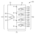
몇몇 실시예들에서, 광학 판독기는 제1 어셈블리 및 제2 어셈블리를 포함하고, 제1 어셈블리 및 제2 어셈블리 각각은 적어도 하나의 광원 및 적어도 하나의 검출기를 포함한다. 광학 판독기는 제1 어셈블리의 적어도 하나의 광원에 의해 방출된 광의 적어도 일부가 광학 분석물 센서의 제1 영역으로부터 반사되어 제1 어셈블리의 적어도 하나의 검출기에 의해 포획되고, 그리고 제2 어셈블리의 적어도 하나의 광원에 의해 방출된 광의 적어도 일부가 광학 분석물 센서의 제2 영역으로부터 반사되어 제2 어셈블리의 적어도 하나의 검출기에 의해 포획되도록 하우징에 부착될 수 있다. 제1 어셈블리 및 제2 어셈블리 중 적어도 하나는 제1 광원 및 제1 검출기를 포함하는 제1 블록, 및 제2 광원 및 제2 검출기를 포함하는 제2 블록을 포함할 수 있다.In some embodiments, the optical reader includes a first assembly and a second assembly, each of the first assembly and the second assembly including at least one light source and at least one detector. The optical reader includes at least a portion of the light emitted by the at least one light source of the first assembly that is reflected from the first region of the optical analyte sensor and captured by the at least one detector of the first assembly, and at least one of the second assembly At least a portion of the light emitted by the light source may be attached to the housing such that it is reflected from the second region of the optical analyte sensor and captured by the at least one detector of the second assembly. At least one of the first assembly and the second assembly may include a first block including a first light source and a first detector, and a second block including a second light source and a second detector.
다른 실시예들에서, 적어도 하나의 광원에 의해 방출된 광의 적어도 일부가 광학 분석물 센서의 제1 영역으로부터 반사되어 적어도 하나의 검출기에 의해 포획된다. 추가적으로, 적어도 하나의 광원에 의해 방출된 광의 적어도 일부가 광학 분석물 센서의 제2 영역으로부터 반사되어 적어도 하나의 검출기에 의해 포획된다.In other embodiments, at least a portion of the light emitted by the at least one light source is reflected from the first region of the optical analyte sensor and captured by the at least one detector. Additionally, at least a portion of the light emitted by the at least one light source is reflected from the second region of the optical analyte sensor and captured by the at least one detector.
본 개시는 다양한 실시예에 대한 하기의 상세한 설명을 첨부된 도면과 관련하여 고려하면 보다 완전하게 이해될 수 있다.
도 1은 본 개시에 따른 필터 시스템의 일례를 보여준다.
도 2는 본 개시에 따른 필터 시스템에서 사용될 수 있는 필터 카트리지를 보여준다.
도 3a 및 3b는 본 개시의 몇몇 예시적인 실시예들에서 사용하기에 적합한 예시적인 광학 분석물 센서를 개략적으로 보여준다.
도 4는 본 개시에 따른 예시적인 광학 판독기를 보여준다.
도 5a는 예시적인 광학 판독기의 예시적인 광원의 스펙트럼, 및 타겟 분석물이 없는 경우의 예시적인 광학 분석물 센서의 스펙트럼을 보여준다.
도 5b는 입사광의 파장에 대한 예시적인 광검출기 민감도를 나타내는 곡선을 보여준다.
도 6은 본 개시에 따른 광학 판독기의 또 다른 예시적인 실시예를 개략적으로 보여준다.
도 7a는 하나 이상의 광대역 광원을 이용하는 광학 판독기의 예시적인 실시예를 보여준다.
도 7b는 상이한 스펙트럼 투과율을 지닌 영역들을 갖는 필터를 개략적으로 보여준다.
도 8a 및 8b는 본 개시에 따른 광학 판독기의 예시적인 실시예의 상이한 측면들을 보여준다.
도 9a는 패턴화된 광학 분석물 센서를 조사하도록 구성된 본 개시에 따른 예시적인 광학 판독기를 보여준다.
도 9b는 패턴화된 광학 분석물 센서를 조사하도록 구성된 본 개시에 따른 또 다른 예시적인 광학 판독기를 보여준다.
도 10은 본 개시에 따른 광학 판독기의 동작을 도시하는 도면이다.
도 11a-11d는 본 개시에 따른 또 다른 예시적인 필터 시스템 및 이러한 필터 시스템의 몇몇 예시적인 구성요소들을 개략적으로 보여준다.
도 12는 본 개시에 따른 제거가능한 하우징 부분의 실시예를 보여준다.
도 13a 및 13b는 부착 기제의 예시적인 실시예들을 보여준다.
도 14a-14c는 상이한 타입의 정합 특징부들을 개략적으로 보여준다.
도 15는 본 개시에 따른 필터 시스템의 또 다른 실시예를 보여준다.
도 16은 본 개시의 예시적인 실시예들에서 사용하기에 적합한 호흡기 카트리지를 보여준다.
도 17a 및 17b는 본 개시에 따른 또 다른 예시적인 필터 시스템을 보여준다.
도 18a 및 18b는 본 개시에 따른 필터 시스템에서 사용될 수 있는 적합한 부착 기제를 도시한다.
도 19는 본 개시에 따른 또 다른 예시적인 필터 시스템을 보여준다.
여러 도면에서의 유사한 도면 부호는 유사한 요소를 나타낸다. 달리 표시되지 않는한, 본 명세서 내의 모든 수치들 및 도면들은 크기조정되지 않았으며 본 발명의 상이한 실시예들을 설명할 목적으로 선택된 것이다. 특히 다양한 구성요소들의 치수들은 단지 예시적인 형태로 표시된 것이며, 다양한 구성요소들의 치수들 간의 관계는, 그리 표시되지 않는한, 도면들로부터 추론되어서는 안된다. "탑", "바텀", "상부", "하부", "밑에", "위에", "앞에", "뒤에", "외측", "내측", "위" 및 "아래", 그리고 "제1", "제2"와 같은 용어들이 본 명세서에서 사용될 수 있으나, 달리 언급되지 않는한 이 용어들은 이들의 상대적 의미로 사용된다는 것이 이해되어야 한다.The present disclosure may be more fully understood upon consideration of the following detailed description of various embodiments in conjunction with the accompanying drawings.
1 shows an example of a filter system according to the present disclosure.
2 shows a filter cartridge that can be used in the filter system according to the present disclosure.
3A and 3B schematically illustrate an example optical analyte sensor suitable for use in some example embodiments of the present disclosure.
4 shows an exemplary optical reader in accordance with the present disclosure.
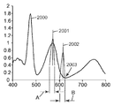
5A shows the spectrum of an exemplary light source of an exemplary optical reader, and the spectrum of an exemplary optical analyte sensor in the absence of a target analyte.
5B shows a curve representing exemplary photodetector sensitivity to the wavelength of incident light.
6 schematically shows another exemplary embodiment of an optical reader according to the present disclosure.
7A shows an exemplary embodiment of an optical reader using one or more broadband light sources.
7b schematically shows a filter with regions with different spectral transmissions.
8A and 8B show different aspects of an exemplary embodiment of an optical reader according to the present disclosure.
9A shows an exemplary optical reader according to the present disclosure configured to illuminate a patterned optical analyte sensor.
9B shows another exemplary optical reader in accordance with the present disclosure configured to illuminate a patterned optical analyte sensor.
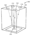
10 is a diagram illustrating operation of an optical reader according to the present disclosure.
11A-11D schematically illustrate another example filter system and some example components of such a filter system according to the present disclosure.
12 shows an embodiment of a removable housing portion according to the present disclosure.
13A and 13B show exemplary embodiments of an attachment base.
14A-14C schematically show different types of mating features.
15 shows another embodiment of a filter system according to the present disclosure.
16 shows a respirator cartridge suitable for use in exemplary embodiments of the present disclosure.
17A and 17B show another exemplary filter system according to the present disclosure.
18A and 18B illustrate suitable attachment mechanisms that can be used in the filter system according to the present disclosure.
19 shows another exemplary filter system according to the present disclosure.
Like reference symbols in the various drawings indicate like elements. Unless otherwise indicated, all figures and figures in this specification are not to scale and have been chosen for the purpose of describing different embodiments of the invention. In particular, the dimensions of the various components are merely shown in an exemplary form, and the relationship between the dimensions of the various components should not be deduced from the figures unless otherwise indicated. "Top", "bottom", "top", "bottom", "below", "top", "before", "behind", "outside", "inside", "up" and "down", and " Terms such as "first" and "second" may be used herein, but it is to be understood that unless otherwise stated, these terms are used in their relative meanings.
하기의 설명에서, 명세서의 일부를 형성하고 몇 개의 특정 실시예가 예로서 도시되어 있는 첨부 도면을 참조한다. 본 발명의 범주 또는 사상으로부터 벗어남이 없이 다른 실시예들이 고려되고 이루어질 수 있음을 이해하여야 한다. 따라서, 하기의 상세한 설명은 제한적인 의미로 취해져서는 안 된다.In the following description, reference is made to the accompanying drawings, which form a part of the specification and in which several specific embodiments are shown by way of example. It is to be understood that other embodiments may be contemplated and made without departing from the scope or spirit of the invention. Accordingly, the following detailed description should not be taken in a limiting sense.
본 명세서에서 사용되는 모든 과학적 및 기술적 용어는 달리 규정되지 않는 한 본 기술 분야에서 공통적으로 사용되는 의미를 가진다. 본 명세서에 제공된 정의는 본 명세서에 빈번하게 사용되는 소정 용어들의 이해를 용이하게 하기 위한 것이며 본 개시의 범주를 제한하고자 하는 것은 아니다.All scientific and technical terms used herein have the meanings commonly used in the art unless otherwise specified. The definitions provided herein are intended to facilitate understanding of certain terms frequently used herein and are not intended to limit the scope of the disclosure.
달리 나타내지 않는 한, 본 명세서 및 특허청구범위에서 사용된 특징부의 크기, 양 및 물리적 특성을 표현하는 모든 수는 모든 경우 용어 "약"에 의해 수식되는 것으로 이해되어야 한다. 따라서, 반대로 나타내지 않는 한, 전술한 명세서 및 첨부된 특허청구범위에 개시된 수치 파라미터는 본 명세서에 개시된 교시 내용을 이용하여 당업자가 얻고자 하는 원하는 특성에 따라 달라질 수 있는 근사치이다.Unless otherwise indicated, all numbers expressing the size, amount, and physical properties of features used in this specification and claims are to be understood as being modified in all instances by the term "about." Thus, unless indicated to the contrary, the numerical parameters set forth in the foregoing specification and appended claims are approximations that may vary depending upon the desired properties sought by those skilled in the art using the teachings disclosed herein.
본 명세서 및 첨부된 특허청구범위에서 사용되는 바와 같이, 단수 형태("a", "an" 및 "the")는 그 내용이 명백하게 다르게 지시하지 않는 한 복수의 지시 대상을 갖는 실시예를 포함한다. 본 명세서 및 첨부된 특허청구범위에서 사용되는 바와 같이, "또는"이라는 용어는 일반적으로 그 내용이 명백하게 다르게 지시하지 않는 한 "및/또는"을 포함하는 의미로 이용된다.As used in this specification and the appended claims, the singular forms “a”, “an” and “the” include embodiments having plural referents unless the content clearly dictates otherwise. . As used in this specification and the appended claims, the term “or” is generally employed in its sense including “and / or” unless the content clearly dictates otherwise.
본 개시는 휘발성 유기 화합물로부터의 보호를 위해 위험한 환경에서 이용되는 호흡기 필터 또는 카트리지의 필터 매체와 같은 필터 매체의 사용 수명 종료와 관련된 정보를 사용자에게 제공하거나 또는 사용 수명 종료를 표시하기 위하여 적용될 수 있는 시스템 및 장치에 관한 것이다. 본 개시는 다양한 필터 시스템들에 대해 보다 정확한 사용 수명 종료의 표시를 제공하도록 도울 것으로 기대된다. 몇몇 예시적인 실시예들은 호흡기 카트리지 및 필터를 위한 액세서리로서 제공될 수 있는 것으로 여겨지나, 반면 다른 예시적인 실시예들은 전체의 호흡기 및 카트리지를 포함한다. 본 개시는 다양한 필터 시스템, 예컨대 전동식 공기 정화 호흡기, 재사용가능한 개인용 호흡기, 일회용 개인용 호흡기를 포함하는 개인용 호흡기, 해즈맷 수트, 집단 방호 필터 및 당업자에게 익숙할 다른 응용들에 적용가능하다.The present disclosure may be applied to provide a user with or indicate an end of service life of a filter medium, such as a filter medium of a respirator filter or cartridge used in a hazardous environment for protection from volatile organic compounds. A system and apparatus are described. This disclosure is expected to help provide a more accurate indication of end of service life for various filter systems. It is believed that some exemplary embodiments may be provided as accessories for a respirator cartridge and filter, while other exemplary embodiments include a full respirator and cartridge. The present disclosure is applicable to various filter systems, such as electric air purifying respirators, reusable personal respirators, personal respirators including disposable personal respirators, Hazmat suits, collective protective filters, and other applications that would be familiar to those skilled in the art.
본 개시의 예시적인 실시예는 하나 이상의 관심대상 분석물을 검출 및/또는 모니터링하기 위하여 사용될 수 있다. 그러한 분석물은 모니터링하기를 원하는 환경 (흔히, 대기(air atmosphere))에 존재할 수 있는 증기 또는 가스를 포함할 수 있다. 몇몇 실시예들에서, 분석물은 유기 증기 (예를 들어, 휘발성 유기 화합물)이다. 대표적인 유기 분석물은 알칸, 사이클로알칸, 방향족 화합물, 알코올, 에테르, 에스테르, 케톤, 할로카본, 아민, 유기산, 시안산염, 질산염, 및 니트릴, 예를 들어 n-옥탄, 사이클로헥산, 메틸 에틸 케톤, 아세톤, 에틸 아세테이트, 이황화탄소, 사염화탄소, 벤젠, 톨루엔, 스티렌, 자일렌, 메틸 클로로포름, 테트라하이드로푸란, 메탄올, 에탄올, 아이소프로필 알코올, n-부틸 알코올, t-부틸 알코올, 2-에톡시에탄올, 아세트산, 2-아미노피리딘, 에틸렌 글리콜 모노메틸 에테르, 톨루엔-2,4-다이아이소시아네이트, 니트로메탄, 아세토니트릴 등을 포함하는 치환 또는 비치환 탄소 화합물을 제한 없이 포함할 수 있다. 본 개시에 따른 광학 분석물 센서의 한가지 특정 타입으로서 유기 증기 센서가 언급되나, 이용될 수 있는 다른 타입의 광학 분석물 센서는 유기 증기, 산성 가스(예를 들어, SO2, C12, HCl, ClO2, HCN, HF, H2S 및 질소의 산화물) 및 기본 가스(예를 들어, 암모니아, 메틸아민)과 같은 반응성 가스, 그리고 염화 시아노겐 및 포름알데히드와 같은 다른 가스에 응답하는 것들을 포함한다.Exemplary embodiments of the present disclosure can be used to detect and / or monitor one or more analytes of interest. Such analytes may include vapors or gases that may be present in the environment (often, air atmosphere) desired to be monitored. In some embodiments, the analyte is organic vapor (eg, volatile organic compounds). Representative organic analytes include alkanes, cycloalkanes, aromatic compounds, alcohols, ethers, esters, ketones, halocarbons, amines, organic acids, cyanates, nitrates, and nitriles such as n-octane, cyclohexane, methyl ethyl ketone, Acetone, ethyl acetate, carbon disulfide, carbon tetrachloride, benzene, toluene, styrene, xylene, methyl chloroform, tetrahydrofuran, methanol, ethanol, isopropyl alcohol, n-butyl alcohol, t-butyl alcohol, 2-ethoxyethanol, Substituted or unsubstituted carbon compounds including acetic acid, 2-aminopyridine, ethylene glycol monomethyl ether, toluene-2,4-diisocyanate, nitromethane, acetonitrile and the like can be included without limitation. One particular type of optical analyte sensor in accordance with the present disclosure is mentioned as organic vapor sensor, but other types of optical analyte sensors that can be used are organic vapor, acid gases (eg, SO 2 , C1 2 , HCl, Oxides of
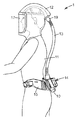
본 개시에 따른 예시적인 필터 시스템이 전동식 공기 정화 호흡기(PAPR)(1)를 개략적으로 보여주는 도 1에 도시된다. PAPR(1)은, 후드(12), 터보 유닛(14), 호흡 튜브(13) 및 벨트(15)와 같은 헤드 탑을 포함한다. 후드(12)는 사용자(11)의 헤드 위에 씌워지고 사용자의 머리를 적어도 부분적으로 에워싸 호흡 존(17)(즉, 사용자의 코와 입 주변의 영역)을 형성하도록 구성되어, 필터링된 공기가 이 호흡 존(17)으로 향하게 된다. 후드가 도 1에 도시되어 있지만, 공기를 사용자의 호흡 존(17)으로 향하게 하기 위해 사용자 얼굴의 적어도 입과 코 영역(orinasal area)을 덮는 밀폐된 사용자 환경이 생성된다면, 후드(12)는 마스크, 헬멧 또는 풀 수트(full suit)와 같은 임의의 다른 적합한 헤드 탑으로 대체될 수 있다. 터보 유닛(14)은 그것을 사용자의 몸통 주변에 고정될 수 있게 해주는 벨트(15)에 부착될 수 있다.An exemplary filter system according to the present disclosure is shown in FIG. 1, which schematically shows an electric air purifying respirator (PAPR) 1. The
터보 유닛(14)은 모터(도시되지 않음)에 의해 구동되는 팬을 사용하여 PAPR 시스템을 통해 공기를 빼내는 송풍기(blower) 시스템(도시되지 않음)을 하우징한다. 터보 유닛은 배터리 팩(10)과 같은 전원을 추가로 포함할 수 있다. 터보 유닛(14)은 터보 유닛(14)의 배출구(outlet)(18)와 후드(12)의 흡입구(inlet)(19) 사이에 연결된 호흡 튜브(13)를 통해 후드(12)에 공기를 공급한다. 터보 유닛(14)은 필터 카트리지(도 2에 도시됨)를 포함하는바, 이 필터 카트리지는 그 내부에 포함된 필터 매체가 공기흐름 경로 내에 있도록 배치되고, 바람직하게는 송풍기의 팬 개구의 상류(upstream)에 배치된다. 본 개시의 전형적인 실시예들에서, 필터 카트리지는 터보 유닛과 관련하여 제거될 수 있으며, 교체가능하다. 필터 카트리지를 제공하는 목적은 공기가 사용자(11)에게 전달되기 전에 주변 공기(ambient air)로부터 입자 및/또는 가스 및/또는 증기와 같은 오염물의 적어도 소정량을 제거하는 것이다.The
본 개시의 실시예들은 임의의 하나 이상의 다양한 필터 매체들을 이용할 수 있으며, 한가지 적합한 카테고리는 흡수흡착(sorbent) 매체이다. 흡수흡착 매체는 의도된 사용 조건 하에서 존재할 것으로 예상되는 관심 대상의 증기를 흡착할 수 있을 것이다. 흡수흡착 매체는 바람직하게는 그를 통한 공기 또는 다른 가스의 신속한 유동을 허용하기에 충분히 다공성이고, 미세 분할된 고체(예컨대 분말, 비드, 플레이크, 결정립 또는 집괴) 또는 다공성 고체(예컨대 개방 셀 발포체)의 형태일 수 있다. 바람직한 흡수흡착 매체 재료는, 활성탄, 제올라이트, 알루미나, 및 흡착에 의해 관심대상 증기를 제거할 수 있는 다른 금속 산화물; 아세트산과 같은 산성 용액 또는 수용성 수산화 소듐(aqueous sodium hydroxide)과 같은 알칼리 용액으로 처리된 점토 및 다른 광물질; 분자체(molecular sieves) 및 다른 제올라이트; 실리카와 같은 다른 무기 흡수흡착제; 및 "스티로소브(Styrosorb)"(예를 들어, 문헌[V. A. Davankov and P. Tsyurupa, Pure and Appl. Chem., vol. 61, pp. 1881-89 (1989)], 그리고 문헌[L. D. Belyakova, T. I. Schevchenko, V. A. Davankov and M.P. Tsyurupa, Adv. in Colloid and Interface Sci. vol. 25, pp. 249-66, (1986)]에 기재됨)로 알려져 있는 고도로 가교된 스티렌계 중합체와 같은 초가교(hypercrosslinked) 시스템을 포함하는 유기 흡수흡착제를 포함한다.Embodiments of the present disclosure may utilize any one or more of a variety of filter media, one suitable category being sorbent media. Absorbent adsorption media will be able to adsorb vapors of interest that are expected to be present under the intended use conditions. Absorbent adsorption media are preferably porous enough to allow rapid flow of air or other gas therethrough, and are preferably composed of finely divided solids (such as powders, beads, flakes, grains or agglomerates) or porous solids (such as open cell foams). It may be in the form. Preferred absorbent adsorption media materials include activated carbon, zeolites, alumina, and other metal oxides capable of removing the vapor of interest by adsorption; Clay and other minerals treated with an acidic solution such as acetic acid or an alkaline solution such as aqueous sodium hydroxide; Molecular sieves and other zeolites; Other inorganic absorbents such as silica; And "Styrosorb" (see, eg, VA Davankov and P. Tsyurupa, Pure and Appl. Chem., Vol. 61, pp. 1881-89 (1989)), and LD Belyakova, Hypercrosslinked, such as a highly crosslinked styrene-based polymer known as TI Schevchenko, VA Davankov and MP Tsyurupa, Adv. In Colloid and Interface Sci. Vol. 25, pp. 249-66, (1986)). ) Organic absorbents comprising the system.
활성탄, 제올라이트, 및 알루미나는 바람직한 흡수흡착 매체의 예이다. 예를 들어, 증기의 혼합물 또는 다른 관심대상 분석물을 흡수하기 위하여 흡수흡착 매체의 혼합물 또는 층이 이용될 수 있다. 미세 분할된 형태에서라면, 흡수흡착 입자 크기는 크게 변할 수 있고 보통은 의도된 사용 조건에 부분적으로 기초하여 선택될 것이다. 일반적인 지침으로서, 미세 분할된 흡수흡착 매체 입자는 약 4 내지 약 3000 마이크로미터의 평균 직경, 예컨대 약 30 내지 약 1500 마이크로미터의 평균 직경으로 크기가 변할 수 있다. 상이한 크기 범위를 갖는 흡수흡착 매체 입자들의 혼합물이 (예컨대 흡수흡착 매체 입자들의 이원 혼합물(bimodal mixture)에, 또는 상류 층 내에 더 큰 흡수흡착 입자를 그리고 하류 층 내에 더 작은 흡수흡착 입자를 채용하는 다층 배열에) 또한 채용될 수도 있다. 미국 특허 제3,971,373호(브라운(Braun) 등), 제4,208,194호(넬슨(Nelson)) 및 제4,948,639호(브루커(Brooker) 등) 및 미국 특허 출원 공개 제2006/0096911 A1호(브레이(Brey) 등)에 설명된 바와 같은 적합한 결합제(예컨대 결합 탄소)와 조합되거나 적합한 지지체 상에 또는 그 내에 포획된 흡수흡착 매체가 또한 이용될 수 있다.Activated carbon, zeolites, and alumina are examples of preferred absorbent media. For example, a mixture or layer of absorbent media may be used to absorb a mixture of vapors or other analytes of interest. In the finely divided form, the adsorptive particle size can vary greatly and will usually be selected based in part on the intended use conditions. As a general guideline, the microdivided absorbent media particles can vary in size to an average diameter of about 4 to about 3000 micrometers, such as an average diameter of about 30 to about 1500 micrometers. A multilayer of adsorbent media particles having different size ranges (e.g., a bimodal mixture of adsorbent media particles, or employing larger absorbent particles in an upstream layer and smaller absorbent particles in a downstream layer) Arrangement) may also be employed. U.S. Pat. Absorbent media can also be used in combination with or captured on or in a suitable support, such as a suitable binder (such as bonded carbon) as described in, etc.).
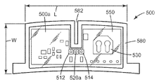
도 2는 도 1과 관련하여 기술된 터보 유닛(14)과 같은 PAPR의 터보 유닛에서 사용될 수 있는 필터 카트리지(100)를 보여준다. 필터 카트리지(100)는 하우징(120) 및 하우징(120) 내에 배치된 흡수흡착 재료(예컨대 활성탄)와 같은 필터 매체(122)를 포함한다. 하기에서 더욱 상세히 설명되는 바와 같이, 광학 분석물 센서(128)(하기에서 더욱 상세히 기술됨)가 또한 필터 매체(122)와 유체 통신하도록 하우징(120)내에 배치된다. 도 2에 도시된 하우징(120)은 복수의 개구들(125)을 갖는 후면 커버(124a) 및 또한 복수의 개구들(도시되지 않음)을 갖는 전면 커버(124b)를 포함한다. 전면 커버(124b) 및 후면 커버(124a) 내의 개구들은 각각 가스 흡입구 및 배출구로서 기능하여, 외부 환경으로부터의 주변 공기가 카트리지(100) 내로, 필터 매체(122)를 통해 그리고 이어서 필터 카트리지(100)가 그 일부인 터보 유닛의 송풍기의 팬 개구 내로 흐를 수 있게 한다. 필요하다면, 커버(124a, 124b) 중 하나 또는 둘 모두의 개구들은 사용될 때까지, 예를 들어, 사용전에 제거될 제거가능한 커버(도시되지 않음)를 사용하여 봉인될 수 있다.FIG. 2 shows a
하우징(120)의 벽(126)은 (광원(들) 및 검출기(들)가 튜닝되는 특정 스펙트럼 범위에서 투명한) 투명부(127)와 같은 뷰잉 포트(viewing port)를 포함할 수 있으며, (하기에서 더 설명될 바와 같이) 뷰잉 포트를 통해 광학 분석물 센서(128)가 조사될 수 있다. 필요하다면, 제거가능하거나 교체가능한 실드 또는 다른 커버(도시되지 않음)가 선택적으로 사용되어 페인트 또는 발포 오버스프레이, 먼지, 또는 다른 옵스큐레이션(obscuration)으로부터 투명부(127)를 보호할 수 있다. 대안적으로, 뷰잉 포트는 하우징(120) 내에 개구를 포함할 수 있다. 몇몇 예시적인 실시예들에서, 하우징의 전체 벽(126) 또는 전체 하우징(120)이 투명할 수 있다. 광학 분석물 센서(128)는, 예를 들어, 필터 매체(122)가 노출 조건에서 분석물과 평형이 될 때 그 광학 특성들 중 적어도 하나에서 변화를 겪음으로써(비색 변화, 밝기 변화, 반사광의 강도 등에 의해 나타날 수 있음), 분석물에 광학적으로 응답한다.The
투명부(127) 및 광학 분석물 센서(128)로 진입하는 광은 이후 투명부(127)를 통해 다시 반사된다. 광학 분석물 센서(128)의 광학 특성들 중 적어도 하나에서의 구별가능한 변화(예를 들어, 녹색에서 적색으로와 같은 반사 스펙트럼에서의 변화, 백색 또는 흑색에서 유색으로 또는 유색에서 백색 또는 흑색으로와 같은 색의 등장 및 소멸, 또는 백색에서 흑색으로 또는 흑색에서 백색으로의 변화)가 광학 분석물 센서(128) 아래의 필터 매체(122)가 노출 조건에서 증기와 평형이 되었음을 표시할 때, 카트리지(100)가 제거되어 새 카트리지로 교체될 것이다. 달리 말하면, 광학 분석물 센서는 광학 변화가 카트리지(100)의 남은 사용 수명 또는 그 사용 수명의 종료를 나타내도록 구성될 수 있다. 일 실시예에서, 광학 분석물 센서(128)는 원하는 남은 사용 수명 퍼센티지에서만 경고를 주도록 흐름 경로의 소정의 위치에 놓일 수 있다.Light entering the
도 3a는 본 개시의 몇몇 예시적인 실시예들에서 사용하기에 적합한 예시적인 광학 분석물 센서의 개략도를 보여준다. 다층 광학 분석물 센서(32)가 투명 기판(33)(광원(들) 및 검출기(들)가 튜닝되는 특정 스펙트럼 범위에서 투명함)과 필터 매체(38) 사이에 배치된다. 예시적인 광학 분석물 센서(32)는 부분 반사층(partially reflective layer)(34), 검출 매체(35), 및 분석물-침투성(analyte-permeable) 반사층(36)을 포함한다. 매체(38)의 적어도 일부와 관심대상 분석물 사이에 적용된 분석물 농도에서 평형이 발생한 때 또는 평형이 발생한 후 곧, 분석물이, 예를 들어, 기공(37)을 통해 검출 매체(35)로, 분석물-침투성 반사층(36)을 통과할 수 있다. 검출 매체(35)는 층의 형태로 제공될 수 있으며, 관심대상 분석물에 노출될 때 그 광학 특성들(예를 들어, 층의 광학 두께) 중 적어도 하나가 변하도록 적합한 재료로 제조되거나 적합한 구조로 제조될 수 있다. 변화는 예컨대, 기판(33)을 통해, 외부에서 검출될 수 있다.3A shows a schematic diagram of an exemplary optical analyte sensor suitable for use in some exemplary embodiments of the present disclosure. A multilayer
광선(39a)으로 표시된 주변 광의 일부가 기판(33)을 통과하고, 부분 반사층(34)으로부터 광선(39b)으로서 반사되고, 기판(33)을 통하여 다시 이동하여, 그후 기판(33) 외부로 나간다. 주변 광선(39a)의 다른 부분은 기판(33), 부분 반사층(34), 및 검출 매체(35)를 통과하여 반사층(36)으로부터 광선(39c)으로서 반사된다. 광선(39c)은 검출층(35), 부분 반사층(34), 및 기판(33)을 통해 다시 이동하고, 그후 기판(33) 외부로 나간다. 검출층(35)을 위한 적절한 초기 두께 또는 변화된 두께가 선택되었다면, 그리고 층들(34, 36)이 충분히 편평하다면, 광선(39b, 39c)과 유사한 광선에 의해 보강 또는 상쇄 간섭(constructive or destructive interference)이 생성될 것이고, 광학 분석물 센서(32)의 하나 이상의 광학 특성의 구별가능한 변화가 부분 반사층(34)을 통해 검출될 수 있다.A portion of the ambient light indicated by the
본 개시에 따른 광학 분석물 센서는 필름 또는 벌크 접착제, 기계적 삽입물(mechanical inserts), 열적 본딩, 초음파 용접 및 이들의 조합을 포함하는 다양한 기술들을 사용하여 필터 하우징 또는 다른 지지체에 부착될 수 있다. 기판은 선택적(optional)이지만, 기판이 존재할 때, 기판은 박막 표시기를 위한 적합하게 투명한 지지체를 제공할 수 있는 다양한 재료로 제조될 수 있다. 기판은 강성(예컨대 유리) 또는 가요성(예컨대 하나 이상의 롤 처리 단계에서 취급될 수 있는 플라스틱 필름)일 수 있다. 적합하게 투명한 플라스틱과 같은 가요성 재료로 제조된다면, 기판은 바람직하게는 충분히 낮은 증기 침투성을 가지며 따라서 관심 대상의 증기(들)가 부분 반사층을 통해 검출 매체 내부로 또는 검출 매체 외부로 투과되지 않을 것이다. 기판이 생략되면, 부분 반사층은 그러한 증기 투과를 방해 또는 방지하도록 충분히 불침투성이어야 한다. 필요하다면, 다공성 기판이 침투성 반사층과 흡수흡착 매체 사이에 위치될 수 있다. 예를 들어, 관심 대상의 증기가 흡수흡착 매체로부터 침투성 기판 및 반사층을 통해 그리고 그후 검출 매체 내로 통과하도록 허용될 수 있다.Optical analyte sensors according to the present disclosure can be attached to filter housings or other supports using a variety of techniques including film or bulk adhesives, mechanical inserts, thermal bonding, ultrasonic welding, and combinations thereof. The substrate is optional, but when present, the substrate can be made from a variety of materials that can provide a suitably transparent support for thin film indicators. The substrate can be rigid (such as glass) or flexible (such as a plastic film that can be handled in one or more roll processing steps). If made from a flexible material, such as a suitably transparent plastic, the substrate is preferably of sufficiently low vapor permeability and therefore no vapor (s) of interest will be transmitted through or partially out of the detection medium through the partially reflective layer. . If the substrate is omitted, the partially reflective layer should be sufficiently impermeable to prevent or prevent such vapor transmission. If desired, a porous substrate can be positioned between the permeable reflective layer and the absorbent medium. For example, vapor of interest may be allowed to pass from the absorbent medium through the permeable substrate and the reflective layer and then into the detection medium.
부분 반사층 및 반사층은 각각 확산 또는 바람직하게는 경면 광 반사(specular light reflection)를 제공하며, 시각적으로 쉽게 인식 가능한 표시기 외양 변화를 제공하도록 적절하게 이격될 때 협동할 수 있는 다양한 재료들로 제조될 수 있다. 적합한 부분 반사층 및 반사층 재료는 금속, 예를 들어 알루미늄, 크롬, 금, 티타늄, 니켈, 규소, 은, 팔라듐, 백금, 티타늄, 및 그러한 금속들을 함유하는 합금; 금속 산화물, 예를 들어 산화크롬, 산화티타늄 및 산화알루미늄; 및 미국 특허 제 5,699,188호(길버트(Gilbert) 등), 제5,882,774호(존자(Jonza) 등) 및 제6,049,419호(휘틀리(Wheatley) 등), 및 PCT 출원공개 제WO 97/01778호(오우더커크(Ouderkirk) 등)에 기술된 다층 광학 필름(복굴절성 다층 광학 필름을 포함)을 포함한다. 부분 반사층과 반사층은 동일하거나 상이할 수 있다. 동시 계류 중인 라코우 등의 미국 특허 출원 공개 제2008/0063874A1호에 설명된 바와 같이, 금속 나노입자 코팅(예컨대 금속 나노입자 잉크)이 반사층을 형성하기 위해 이용될 수 있다.The partially reflective layer and the reflective layer can each be made of a variety of materials that provide diffusion or, preferably, specular light reflection, and can cooperate when properly spaced to provide a visually easily recognizable indicator appearance change. have. Suitable partially reflective layers and reflective layer materials include metals such as aluminum, chromium, gold, titanium, nickel, silicon, silver, palladium, platinum, titanium, and alloys containing such metals; Metal oxides such as chromium oxide, titanium oxide and aluminum oxide; And U.S. Pat. Multilayer optical films (including birefringent multilayer optical films) described in Oudkirk et al.). The partial reflecting layer and the reflecting layer may be the same or different. As described in co-pending US patent application publication 2008 / 0063874A1 to Lakou et al., Metal nanoparticle coatings (such as metal nanoparticle inks) may be used to form the reflective layer.
부분 반사층은 반사층보다 덜 반사성이고, 일부 입사광을 투과시킨다. 부분 반사층은, 예를 들어 약 2 내지 약 50 나노미터(㎚)의 물리적 두께, 약 20 내지 약 80%의 500 ㎚에서의 광 투과율, 및 약 80 내지 약 20%의 500 ㎚에서의 반사율, 또는 이들 사이의 임의의 수치를 가질 수 있다. 부분 반사층 자체는 증기에 대해 불침투성일 수 있고(그러한 경우, 바람직하게는 연속적임), 적합한 기판 상에 또는 달리 그에 인접하게 선택적으로 코팅될 수 있다. 부분 반사층은 또한 증기에 대해 침투성일 수도 있고 (그러하다면, 예를 들어 불연속적이거나 반연속적일 수 있고), 적합한 증기 불침투성 기판 상에 또는 달리 그에 인접하여 코팅될 수 있다. 검출층에 인접한 부분 반사층의 면은 바람직하게는 약 ± 10 ㎚ 이내로 편평하다.The partially reflective layer is less reflective than the reflective layer and transmits some incident light. The partial reflecting layer may, for example, have a physical thickness of about 2 to about 50 nanometers (nm), a light transmittance at 500 nm of about 20 to about 80%, and a reflectance at 500 nm of about 80 to about 20%, or It can have any number between them. The partially reflective layer itself may be impermeable to steam (and in this case preferably continuous) and may be selectively coated on or otherwise adjacent to a suitable substrate. The partially reflective layer may also be permeable to steam (if so, for example, discontinuous or semicontinuous) and may be coated on or otherwise adjacent to a suitable vapor impermeable substrate. The face of the partially reflective layer adjacent to the detection layer is preferably flat within about ± 10 nm.
반사층은, 예를 들어 약 1 내지 약 500 ㎚의 물리적 두께, 약 0 내지 약 80%의 500 ㎚에서의 광 투과율, 및 약 100 내지 약 20%의 500 ㎚에서의 반사율을 가질 수 있다. 반사층은 바람직하게는 다공성이거나, 패턴화되거나, 불연속적이거나, 반연속적이거나 또는 달리 충분히 침투성이어서, 증기가 흡수흡착 매체로부터 반사층을 통해 검출 매체 내로 들어갈 수 있도록 한다. 원하는 기공 또는 불연속성은 적합한 침착 기술을 통해 또는 선택적 에칭, 반응성 이온 에칭 또는 패턴화된 레이저 제거와 같은 적절한 침착후(post-deposition) 처리를 통해 달성될 수 있다. 반사층은 또한 패킹된 나노입자들의 증기 침투성 층을 형성하도록 전술된 미국 특허 출원 공개 제2008/0063874A1호에 설명된 바와 같이 증기 침투성 금속 나노입자 층을 침착함으로써 형성될 수도 있고, 기공은 나노입자들 사이의 간극에 의해 제공된다.The reflective layer can have, for example, a physical thickness of about 1 to about 500 nm, a light transmittance at 500 nm of about 0 to about 80%, and a reflectance at 500 nm of about 100 to about 20%. The reflective layer is preferably porous, patterned, discontinuous, semicontinuous or otherwise sufficiently permeable to allow vapor to enter the detection medium from the absorbent medium through the reflective layer. Desired porosity or discontinuity can be achieved through suitable deposition techniques or through appropriate post-deposition treatments such as selective etching, reactive ion etching or patterned laser ablation. The reflective layer may also be formed by depositing a vapor permeable metal nanoparticle layer as described in US Patent Application Publication No. 2008 / 0063874A1 described above to form a vapor permeable layer of packed nanoparticles, the pores being between nanoparticles. Provided by the gap.
검출 매체 혼합물은 균질 또는 비균질일 수 있고, 예를 들어 무기 성분들의 혼합물, 유기 성분들의 혼합물, 또는 무기 및 유기 성분들의 혼합물로 제조될 수 있다. 성분들의 혼합물로 제조된 검출 매체는 분석물 그룹의 개선된 검출을 제공할 수 있다. 검출 매체는 바람직하게는 흡수흡착 매체와 유사한 증기 수착(vapor sorption) 특성을 제공하도록 선택된 일정 범위의 기공 크기 또는 표면적을 갖는다. 적합한 다공성은 미국 특허 제6,573,305 B1호(썬호스트(Thunhorst) 등)에 설명되어 있는 것과 같은, 높은 내부 상 에멀전으로 제조된 발포체와 같은 다공성 재료를 사용함으로써 얻어질 수 있다. 다공성은 또한 미공성 재료를 생성하기 위한 이산화탄소 발포(문헌["Macromolecules", 2001, vol. 34, pp. 8792-8801] 참조)를 통해, 또는 중합체 블렌드들의 나노상 분리(문헌["Science", 1999, vol. 283, p. 520] 참조)에 의해 얻어질 수 있다. 대체로, 기공 직경은 바람직하게는 원하는 표시기 색상의 피크 파장보다 더 작다. 예컨대 약 0.5 내지 약 20 ㎚, 0.5 내지 약 10 ㎚, 또는 0.5 내지 약 5 ㎚의 평균 기공 크기를 갖는 나노 크기의 기공이 바람직하다.The detection medium mixture can be homogeneous or heterogeneous and can be made, for example, of a mixture of inorganic components, a mixture of organic components, or a mixture of inorganic and organic components. Detection media prepared from mixtures of components can provide improved detection of analyte groups. The detection medium preferably has a range of pore sizes or surface areas selected to provide vapor sorption properties similar to the adsorption medium. Suitable porosity can be obtained by using a porous material, such as a foam made of a high internal phase emulsion, such as described in US Pat. No. 6,573,305 B1 (Thunhorst et al.). Porosity can also be achieved through carbon dioxide foaming (see "Macromolecules", 2001, vol. 34, pp. 8792-8801) to produce microporous materials, or by nanophase separation of polymer blends ("Science", 1999, vol. 283, p. 520). In general, the pore diameter is preferably smaller than the peak wavelength of the desired indicator color. Nano-sized pores having an average pore size of, for example, about 0.5 to about 20 nm, 0.5 to about 10 nm, or 0.5 to about 5 nm are preferred.
대표적인 무기 검출 매체 재료는 다공성 실리카, 금속 산화물, 금속 질화물, 금속 산질화물 및 광학 간섭에 의해 색 또는 비색 변화를 생성하기에 적절한 두께의 투명한 다공성 층으로 형성될 수 있는 다른 무기 재료를 포함한다. 예를 들어, 무기 검출 매체 재료는 산화규소, 질화규소, 산질화규소, 산화알루미늄, 산화티타늄, 질화티타늄, 산질화티타늄, 산화주석, 산화지르코늄, 제올라이트 또는 이들의 조합일 수 있다. 다공성 실리카가 그의 강인성 및 습식 에칭 처리와의 양립성으로 인해 특히 바람직한 무기 검출 매체 재료이다.Representative inorganic detection media materials include porous silica, metal oxides, metal nitrides, metal oxynitrides, and other inorganic materials that may be formed into a transparent porous layer of a thickness suitable to produce color or colorimetric changes by optical interference. For example, the inorganic detection medium material may be silicon oxide, silicon nitride, silicon oxynitride, aluminum oxide, titanium oxide, titanium nitride, titanium oxynitride, tin oxide, zirconium oxide, zeolite, or a combination thereof. Porous silica is a particularly preferred inorganic detection media material because of its toughness and compatibility with wet etching treatment.
다공성 실리카는, 예를 들어 졸-겔 처리 루트를 사용하여 제조될 수 있고 유기 템플릿과 함께 또는 유기 템플릿이 없이 제조될 수 있다. 예시적인 유기 템플릿은 계면 활성제, 예컨대 알킬트라이메틸암모늄염, 폴리(에틸렌옥사이드-코-프로필렌 옥사이드) 블록 공중합체 및 당업자에게 명백할 다른 계면 활성제 또는 중합체와 같은 음이온성 또는 비이온성 계면활성제를 포함한다. 졸-겔 혼합물은 규산염으로 변환될 수 있고, 유기 템플릿은 제거되어 실리카 내에 미세 기공의 네트워크를 남길 수 있다. 대표적인 다공성 실리카 재료가 문헌[Ogawa et al., Chem. Commun. pp. 1149-1150 (1996), in Kresge et al., Nature, Vol. 359, pp. 710-712 (1992), in Jia et al., Chemistry Letters, Vol. 33(2), pp. 202-203 (2004)] 및 미국 특허 제5,858,457호(브링커(Brinker) 등)에 기술되어 있다. 다양한 유기 분자가 또한 유기 템플릿으로서 채용될 수 있다. 예를 들어, 포도당 및 만노스와 같은 당이 다공성 규산염을 생성하기 위한 유기 템플릿으로서 사용될 수 있다(문헌[Wei et al, Adv. Mater.1998, Vol. 10, p. 313 (1998)]참조). 유기 치환 실록산 또는 유기 비스-실록산이 졸-겔 조성물 내에 포함되어, 미세 기공을 더 소수성으로 만들고 수증기의 흡착을 제한할 수 있다. 플라즈마 화학 증착이 또한 다공성 무기 검출 재료를 생성하기 위해 채용될 수 있다. 이러한 방법은 대체로 가스 전구체로부터 플라즈마를 형성함으로써 분석물 검출층을 형성하는 단계와, 비정질 무작위 공유 네트워크 층을 형성하기 위해 기판 상에 플라즈마를 침착시키는 단계와, 그 다음 미공성 비정질 무작위 공유 네트워크 층을 형성하기 위해 비정질 공유 네트워크 층을 가열하는 단계를 포함한다. 그러한 재료의 예는 미국 특허 제6,312,793호 (그릴(Grill) 등) 및 미국 특허 공개 제2007/0141580A1호 (모세(Moses) 등)에 기술된다.Porous silica can be prepared, for example, using a sol-gel treatment route and can be prepared with or without an organic template. Exemplary organic templates include anionic or nonionic surfactants such as surfactants such as alkyltrimethylammonium salts, poly (ethyleneoxide-co-propylene oxide) block copolymers and other surfactants or polymers that will be apparent to those skilled in the art. The sol-gel mixture can be converted to a silicate and the organic template can be removed leaving a network of micropores in the silica. Representative porous silica materials are described in Ogawa et al., Chem. Commun. pp. 1149-1150 (1996), in Kresge et al., Nature, Vol. 359, pp. 710-712 (1992), in Jia et al., Chemistry Letters, Vol. 33 (2), pp. 202-203 (2004) and US Pat. No. 5,858,457 (Brinker et al.). Various organic molecules can also be employed as the organic template. For example, sugars such as glucose and mannose can be used as organic templates for producing porous silicates (see Wei et al, Adv. Mater. 1998, Vol. 10, p. 313 (1998)). Organic substituted siloxanes or organic bis-siloxanes can be included in the sol-gel composition to make the micropores more hydrophobic and limit the adsorption of water vapor. Plasma chemical vapor deposition may also be employed to create the porous inorganic detection material. Such methods generally include forming an analyte detection layer by forming a plasma from a gas precursor, depositing a plasma on the substrate to form an amorphous random shared network layer, and then forming a microporous amorphous random shared network layer. Heating the amorphous shared network layer to form. Examples of such materials are described in US Pat. No. 6,312,793 (Grill et al.) And US Patent Publication No. 2007 / 0141580A1 (Moses et al.).
대표적인 유기 검출 매체 재료는 소수성 아크릴레이트 및 메타크릴레이트, 2작용성 단량체, 비닐 단량체, 탄화수소 단량체(올레핀), 실란 단량체, 플루오르화 단량체, 하이드록실화 단량체, 아크릴아미드, 무수물, 알데히드-작용화된 단량체, 아민- 또는 아민염-작용화된 단량체, 산-작용화된 단량체, 에폭사이드-작용화된 단량체, 및 이들의 혼합물 또는 조합을 포함한 단량체의 부류로부터 제조되거나 제조가능한 중합체, (블록 공중합체를 포함한) 공중합체, 및 이들의 혼합물을 포함한다. 전술한 미국 특허 출원 공개 제2004/0184948 A1호는 그러한 단량체들의 포괄적인 목록을 포함하고, 추가의 세부 사항에 대해서는 이를 참조한다. 전술한 고유 미공성을 갖는 중합체(polymer having intrinsic microporosity, PIM)가 특히 바람직한 검출 매체를 제공한다. PIM은 전형적으로 미공성 고체를 형성하는 비네트워크 중합체이다. 전형적으로 높은 강성 및 뒤틀린 분자 구조로 인해, PIM은 공간을 효율적으로 충전할 수 없어서, 개시된 미공성 구조를 제공한다. 적합한 PIM은 문헌[Polymers of intrinsic microporosity (PIMs): robust, solution-processable, organic microporous materials," Budd et al., Chem. Commun., 2004, pp. 230-231]에 개시된 중합체를 포함하지만 이로 한정되지 않는다. 추가적인 PIM이 문헌[Budd et al., J. Mater. Chem., 2005, 15, pp. 1977-1986, in McKeown et al., Chem. Eur. J. 2005, 11, No. 9, 2610-2620], 및 PCT 출원 공개 WO 2005/012397 A2호(맥권(McKeown) 등)에 개시되어 있다.Representative organic detection media materials include hydrophobic acrylates and methacrylates, difunctional monomers, vinyl monomers, hydrocarbon monomers (olefins), silane monomers, fluorinated monomers, hydroxylated monomers, acrylamides, anhydrides, aldehyde-functionalized Polymers prepared or preparable from the class of monomers, including monomers, amine- or amine salt-functionalized monomers, acid-functionalized monomers, epoxide-functionalized monomers, and mixtures or combinations thereof, (block copolymers Copolymers), and mixtures thereof. U.S. Patent Application Publication No. 2004/0184948 A1, supra, contains a comprehensive list of such monomers, see further details for further details. The polymer having intrinsic microporosity (PIM) described above provides a particularly preferred detection medium. PIM is typically a nonnetworked polymer that forms a microporous solid. Due to the typically high stiffness and twisted molecular structure, the PIM cannot fill the space efficiently, providing the disclosed microporous structure. Suitable PIMs include, but are not limited to, polymers disclosed in Polymers of intrinsic microporosity (PIMs): robust, solution-processable, organic microporous materials, "Budd et al., Chem. Commun., 2004, pp. 230-231. Additional PIM is described in Bud et al., J. Mater. Chem., 2005, 15, pp. 1977-1986, in McKeown et al., Chem. Eur. J. 2005, 11, No. 9, 2610-2620, and PCT Application Publication WO 2005/012397 A2 (McKeown et al.).
유기 검출 매체 내의 하나 이상의 중합체들이 적어도 부분적으로 가교될 수 있다. 가교결합은 기계적 안정성 및 특정 분석물에 대한 민감도를 증가시킬 수 있기 때문에 몇몇 실시 형태에서 바람직할 수 있다. 가교결합은 하나 이상의 다작용성 단량체를 검출 매체 내로 혼입함으로써, 검출 매체를 예컨대 전자 빔 또는 감마 선 처리를 받게 함으로써, 검출 매체 내에 배위 화합물 또는 이온성 화합물을 첨가하거나 형성함으로써, 또는 검출 매체 내에 수소 결합을 형성함으로써 달성될 수 있다. 일 예시적인 실시예에서, 가교결합은 후에 가교결합된 시스템으로부터 추출될 수 있는 포로겐(porogen)이 존재하는 데서 수행되어 다공성 검출 매체를 생성할 수 있다. 적합한 포로겐은 노멀 알칸(normal alkane)(예컨대 데칸) 또는 방향족(예컨대 벤젠 또는 톨루엔)과 같은 불활성 유기 분자를 포함하지만 이로 한정되지 않는다. 다른 가교결합된 중합체는 전술한 고도로 가교결합된 스티렌계 중합체를 포함한다.One or more polymers in the organic detection medium may be at least partially crosslinked. Crosslinking may be desirable in some embodiments because it may increase mechanical stability and sensitivity to certain analytes. Crosslinking involves the incorporation of one or more multifunctional monomers into a detection medium, subjecting the detection medium to electron beam or gamma ray treatment, for example, by adding or forming a coordination compound or an ionic compound in the detection medium, or hydrogen bonding within the detection medium. It can be achieved by forming a. In one exemplary embodiment, crosslinking can be performed in the presence of porogen, which can later be extracted from the crosslinked system to create a porous detection medium. Suitable porogens include, but are not limited to, inert organic molecules such as normal alkane (such as decane) or aromatics (such as benzene or toluene). Other crosslinked polymers include the highly crosslinked styrenic polymers described above.
필요하다면, 검출 매체 재료는 그의 표면 특성 또는 흡착 특성을 개질시키도록 처리될 수 있다. 다양한 그러한 처리가, 예컨대 무기 검출 매체의 미세기공을 적합한 유기실란 화합물에 노출시킴으로써 채용될 수 있다. 검출 매체는 아울러 또는 그 대신에 부분 반사층 또는 반사층과 검출 매체 사이의 접착을 증진시키기 위해 적합한 접착 증진 재료(예컨대 티타늄 또는 다른 적합한 금속으로 제조된 결속층)로 처리될 수 있다. 그러한 처리는 또한 검출 매체에 대한 접착을 증진시키기 위해 부분 반사층 또는 반사층에 적용될 수 있다.If desired, the detection media material can be treated to modify its surface or adsorptive properties. Various such treatments can be employed, for example, by exposing the micropores of the inorganic detection medium to a suitable organosilane compound. The detection medium may, in addition or instead, be treated with a suitable reflective enhancement material (such as a tie layer made of titanium or other suitable metal) to promote adhesion between the reflective layer or the reflective medium. Such treatment may also be applied to the partial reflective layer or reflective layer to promote adhesion to the detection medium.
많은 응용에서, 검출 매체는 바람직하게는 소수성이다. 이는 수증기(또는 액체 물)가 검출 매체의 광학 두께의 변화를 일으켜서 분석물의 검출, 예를 들어 유기 용제 증기의 검출을 방해할 가능성을 감소시킬 것이다. 검출 매체는 단일 층 또는 둘 이상의 하위층들(sublayers)로 제조될 수 있다. 하위층들은 다양한 구성을 가질 수 있다. 예를 들어, 이들은 나란히 배열되거나 적층될 수 있다. 하위층들은 또한 상이한 관심 대상의 증기들을 흡수하도록 선택된 상이한 재료들로 제조될 수 있다.In many applications, the detection medium is preferably hydrophobic. This will reduce the likelihood that water vapor (or liquid water) will cause a change in the optical thickness of the detection medium and thereby interfere with the detection of the analyte, for example the detection of organic solvent vapors. The detection medium may be made of a single layer or two or more sublayers. Sublayers can have a variety of configurations. For example, they can be arranged side by side or stacked. Sublayers may also be made of different materials selected to absorb different vapors of interest.
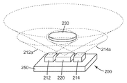
본 개시의 실시예들에서 사용하기에 적합한 광학 분석물 센서의 또 다른 예시적인 실시예가 도 3b에 도시된다. 도 3b에 도시된 바와 같이, 광학 분석물 센서(40)는 관심대상 분석물에 대해 제1 응답을 보이는 하나 이상의 제1 영역(42) 및 관심대상 분석물에 대해 제2의 상이한 응답을 보이는 하나 이상의 제2 영역(44)을 포함할 수 있다. 이러한 광학 분석물 센서는 본 명세서에서 패턴화된 광학 분석물 센서로 언급된다. 도시된 실시예에서, 광학 분석물 센서(40)는, 검출 매체(48), 반반사(semi-reflective)층(50), 및 반사층(52)을 포함하는 다중층 구성을 가진다. 검출 매체(48)는 층의 형태로 제공될 수 있고 관심대상 분석물에 노출될 때 그 광학 특성들 중 적어도 하나(예를 들어, 층의 광학 두께)가 변화하도록 적합한 재료로 제조되거나 적합한 구조로 제조될 수 있다. 변화는 외부로부터, 예컨대 하우징의 벽을 포함할 수 있는 기판(46)을 통해 검출될 수 있다.Another exemplary embodiment of an optical analyte sensor suitable for use in embodiments of the present disclosure is shown in FIG. 3B. As shown in FIG. 3B, the
변화는 제1 영역(42)과 제2 영역(44)에서 상이할 것으로 예측된다. 이용되는 검출기에 의해 구별되는 임의의 검출가능한 차이가 본 개시의 범주 내에 있다. 예를 들어, 관심대상 분석물에 노출됨에 응답하여, 본 개시에 따른 광학 분석물 센서의 상이한 영역들이 상이한 크기의 스펙트럼 시프트, 예컨대 상이한 피크 파장 시프트, 상이한 강도의 반사 광, 또는 이 둘 모두를 겪을 수 있다. 몇몇 검출기들은 1 ㎚ 만큼 작은 색상 시프트 차를 검출할 수 있다. 반반사층(50)은 일반적으로 증기에 의해 침투되지 않는다. 반사층(52)은 일반적으로 화학 물질에 대해 침투성이고 필터 매체(60)와 유체 통신하여, 관심대상 분석물이 반사층(52)을 통과하여 검출 매체(48) 내로 들어갈 수 있고 그리고 검출 매체의 적어도 하나의 광학 특성, 예컨대 그 광학 두께를 충분히 변화시켜 조사시 본 개시에 따라 광학 판독기에 의해 검출될 수 있는 변화를 유발할 수 있도록 한다. 하우징 벽(46)의 내부 표면에 센서(40)를 고정시키기 위해 접착제(53)가 사용될 수 있다.The change is expected to be different in the
관심대상 분석물에 대해 제1 응답을 보이는 하나 이상의 제1 영역 및 관심대상 분석물에 대해 제2의 상이한 응답을 보이는 하나 이상의 제2 영역을 포함하는 광학 분석물 센서를 생산하는 한가지 방법은, 필터 매체(60)와 유체 통신하는 광학 분석물 센서(40) 표면의 일부 위에 폐색층(54)을 배치하는 것에 의한 것이다. 도시된 실시예에서, 폐색층(54)은 제2 영역(44)의 대향하는 측면들 위에 배치되며, 이 제2 영역(44)은 하나 이상의 관심대상 분석물에 노출됨에 응답하여 색상을 변화시킨다. 폐색층(54)은 계면(56)에 직접 또는 하나 이상의 중간 층들을 통해 반사층(52)에 본딩될 수 있다. 계면(56)은 접착층일 수 있다.One method of producing an optical analyte sensor comprising at least one first region exhibiting a first response to an analyte of interest and at least one second region exhibiting a second different response to an analyte of interest is a filter. By placing the
광학 분석물 센서 바디(58)에 본딩된 비활성 폐색층(54)이 없는 경우, 센서는 일반적으로 영역(42, 44)에서 그 광학 특성들 중 적어도 하나의 유사한 변화를 겪을 것이다. 그러나, 폐색층(54)이 바디(58) 위에 배치될 때, 폐색층(54)에 의해 마스킹된 구역(예컨대 영역(42))에 대응하는 영역에서 센서가 그 광학 특성들 중 적어도 하나의 변화를 겪을 것으로 예측되지 않는다. 그러나, 센서는 폐색층(54)에 의해 마스킹되지 않은 구역(예컨대 영역(44))에 대응하는 영역에서 그 광학 특성들 중 적어도 하나의 변화를 겪을 것으로 예측된다. 그러나, 몇몇 실시예들에서 영역(42, 44)이 인접하거나 통합되어 있을 수 있으므로, 위에 언급된 변화는 점진적인(progressive) 변화일 수 있다. 영역(42)과 영역(44) 사이의 경계는 급격(abrupt)하거나 완만한(gradual) 것일 수 있다. 다른 예시적인 실시예들에서, 영역들이 인접하지 않을 수 있다. 위에서 기술된 것과 같은 폐색층(들)이 센서에 적용되어 본 개시에 따른 조사에 유용한 다양한 상이한 가시적 패턴을 생성할 수 있다.In the absence of an
일 실시예에서, 폐색층을 형성하기 위하여 감압 접착제(pressure-sensitive adhesive)와 같은 접착제가 사용될 수 있다. 폴리아이소부틸렌(PIB) 접착제는 특히 그 고 순도에 기초하여 이들 층들을 위한 유용한 재료이다. 본 개시의 실시예들에서 유용한 이러한 구매가능한 아크릴-기반 감압 접착 전사 테이프의 일 예는 상표명 VLO 6690로 알려져 있는 3M사의 접착 전사 테이프이다. 필름 바디 마스킹에 유용한 다른 감압 접착제가 아크릴-기반 접착제를 포함할 수 있다. 일 실시예에서, 감압 접착제는 감압 테이프의 형태로 센서에 적용될 수 있고, 감압 테이프는 라이너 및/또는 배킹(backing)을 추가로 포함할 수 있다. 이 구현예에서, 라이너 및/또는 배킹은 종종 증기의 센서 내로의 침투에 대한 추가적인 장벽을 제공한다. 핫 멜트 솔루션-프리 접착제(Hot melt, solution-free, adhesive)가 또한 마스킹 재료로서 적용될 수 있다. UV로 또는 열적으로 경화가능한 수용성 중합체 또는 에폭시 재료와 같은 중합체 재료가 또한 센서의 영역들을 마스킹하기 위한 폐색층으로서 사용될 수 있다. 왁스, 수지 또는 무기 재료가 또한 폐색층을 위해 사용될 수 있다.In one embodiment, an adhesive, such as a pressure-sensitive adhesive, may be used to form the occlusion layer. Polyisobutylene (PIB) adhesives are particularly useful materials for these layers based on their high purity. One example of such a commercially available acrylic-based pressure sensitive adhesive transfer tape useful in embodiments of the present disclosure is 3M's adhesive transfer tape known under the trade name VLO 6690. Other pressure sensitive adhesives useful for film body masking may include acrylic-based adhesives. In one embodiment, the pressure sensitive adhesive may be applied to the sensor in the form of a pressure sensitive tape, and the pressure sensitive tape may further comprise a liner and / or backing. In this embodiment, the liner and / or backing often provide an additional barrier to the penetration of vapor into the sensor. Hot melt, solution-free, adhesives may also be applied as masking materials. Polymeric materials, such as water soluble polymers or epoxy materials that are curable with UV or thermally, may also be used as the occlusion layer for masking areas of the sensor. Waxes, resins or inorganic materials may also be used for the occlusion layer.
추가적으로 또는 대안적으로, 예시적인 광학 분석물 센서의 임의의 다른 층 또는 하위층들의 세트 중 하나가 불연속적이거나 패터닝되어 관심대상 분석물에 대해 제1 응답을 보이는 하나 이상의 제1 영역 및 관심대상 분석물에 대해 제2의 상이한 응답을 보이는 하나 이상의 제2 영역을 달성할 수 있다. 층 또는 하위층 패턴은 또한 특정 분석물에 대해 반응하는 하나 이상의 부분 및 동일한 분석물에 대해 반응하지 않는 하나 이상의 부분을 제공함으로써 형성될 수 있다. 반응성 재료의 패턴은 또한, 예컨대 분석물이 흡수될 때까지 광학 두께의 차이가 전혀 보이지 않도록 패턴화된 층을 충분히 얇게 제조함으로써, 더 큰 비반응성 하위층 상에 침착될 수 있다. 검출층의 두께는 또한, 예컨대 미국 특허 제6,010,751호(쇼(Shaw) 등)에 설명된 것와 같이, 패턴화될 수 있다. 이는 패턴이 (예를 들어, 더 얇은 부분이 더 두꺼운 부분과 동일한 두께로 팽창하는 경우) 소멸하거나 (예를 들어, 일부가 인접 부분보다 더 작은 두께로 수축하는 경우) 나타나는 것을 허용할 수 있다. 필요하다면, 불연속성은 원하는 형상 또는 형태의 패턴으로 반사층 내에 형성될 수 있다. 이는 관심 대상 분석물에 대한 노출 시에 구분 가능한 패턴이 출현 또는 소멸하게 할 수 있다. 몇몇 경우에, 그러한 패턴의 대조되는 광학 특성을 검출하는 것이 전체 표시기 필름에서의 광학 변화를 검출하는것보다 쉬울 수 있다.Additionally or alternatively, one or more first regions and analytes of interest where one of any other layer or set of sublayers of the exemplary optical analyte sensor is discontinuous or patterned to show a first response to the analyte of interest. It is possible to achieve one or more second regions that exhibit a second different response to. The layer or sublayer pattern can also be formed by providing one or more portions that react to a particular analyte and one or more portions that do not react to the same analyte. The pattern of reactive material may also be deposited on a larger non-reactive sublayer, such as by making the patterned layer sufficiently thin so that no difference in optical thickness is visible until the analyte is absorbed. The thickness of the detection layer can also be patterned, for example as described in US Pat. No. 6,010,751 (Shaw et al.). This may allow the pattern to disappear (eg when the thinner portion expands to the same thickness as the thicker portion) or to disappear (eg when the portion shrinks to a smaller thickness than the adjacent portion). If desired, discontinuities can be formed in the reflective layer in a pattern of the desired shape or shape. This may cause a distinguishable pattern to appear or disappear upon exposure to the analyte of interest. In some cases, detecting the contrasting optical properties of such a pattern can be easier than detecting the optical change in the overall indicator film.
개시된 장치는 필요하다면 추가의 층 또는 요소를 포함할 수 있다. 예를 들어, (예를 들어, 전술한 미국 특허 제4,208,194호에 기술되어 있는 바와 같은 피브릴화(fibrillated) PTFE의 매트릭스 내에 활성탄 입자가 매립된 웨브인) 흡수흡착제가 담지된 복합체(sorbent-loaded composite)의 다공성 층이 반사층과 흡수흡착 매체 사이에 배치되어, 표시기 내로 침투하는 증기를 균질화하거나 달리 흡수흡착 매체 내의 상태에 대한 표시기 응답을 완화시킬 수 있다.The disclosed apparatus can include additional layers or elements if desired. For example, a sorbent-loaded (eg, a web in which activated carbon particles are embedded in a matrix of fibrillated PTFE as described in U.S. Pat. No. 4,208,194, supra). A porous layer of composite may be disposed between the reflective layer and the absorbent medium to homogenize vapors that penetrate into the indicator or otherwise mitigate the indicator response to conditions in the absorbent medium.
본 개시에 따른 광학 분석물 센서에서 사용하기에 적합한 다양한 구조 및 재료가, 예를 들어, 발명의 명칭이 "침투성 나노입자 반사기(Permeable Nanoparticle Reflector)"인 미국 특허 출원 공개 제2008/0063874A1호, 발명의 명칭이 "비활성 폐색층을 갖는 패턴화된 화학 센서(Patterned Chemical Sensor Having Inert Occluding Layer)"인 미국 특허 출원 제12/604,565호, 발명의 명칭이 "비색 센서(Colorimetric Sensor)"인 미국 특허 제7,449,146호에 기술된다. 발명의 명칭이 "비활성 폐색층을 갖는 패턴화된 화학 센서(Patterned Chemical Sensor Having Inert Occluding Layer)"인 공동 소유된 미국 특허 출원 공개 제 2008/0063575A1 및 미국 특허 출원 제12/604,565는 유기 증기 흡수흡착 보호 장치의 사용자에게 카트리지의 사용 수명의 종료 또는 남은 사용 수명을 표시하는 정보를 제공하기 위하여 표시기의 외양에 가시적으로 구별가능한 변화를 사용하는 것을 기술한다. 이 출원에서, 표시기의 외양 변화는 주변 광하에서 가시적으로 모니터링될 수 있다.Various structures and materials suitable for use in the optical analyte sensor according to the present disclosure are described, for example, in US Patent Application Publication No. 2008 / 0063874A1, entitled “Permeable Nanoparticle Reflector”. U.S. Patent Application No. 12 / 604,565, entitled "Patterned Chemical Sensor Having Inert Occluding Layer", U.S. Patent Application entitled "Colorimetric Sensor" 7,449,146. Co-owned US Patent Application Publication No. 2008 / 0063575A1 and US Patent Application No. 12 / 604,565, entitled “Patterned Chemical Sensor Having Inert Occluding Layer,” are named organic vapor absorption adsorption. It describes the use of visually discernible changes in the appearance of the indicator to provide the user of the protective device with information indicating the end of the useful life of the cartridge or the remaining service life. In this application, the appearance change of the indicator can be visually monitored under ambient light.
그러나, 본 개시의 실시예들은 타겟 분석물에 응답하여 광학 분석물 센서의 광학 특성들 중 적어도 하나의 변화를 검출하도록 구성된 광학 판독기를 포함하거나 또는 이러한 광학 판독기에 관한 것이다. 따라서, 본 개시는 색상 변화 센서에 대한 사용자의 시각적 체크에 의존함이 없이 정확한 사용 수명 종료 표시를 제공할 수 있다. 사용자에 의한 필름의 시각적 체크가 몇몇 분석물들에 대해 사용 수명 종료 표시를 제공할 수 있으나, 다른 경우에, 특히 분석물 농도가 낮은 상태에서, 몇몇 관심대상의 휘발성 유기 화합물들은 뚜렷한 색상 변화를 발생시키지 않는다. 다른 한편으로, 몇몇 분석물들은 매우 큰 색상 시프트를 발생시켜 광학 분석물 센서를 그것의 본래 색상으로 되돌아가게 만들며, 이는 때때로 랩 어라운드 효과(wrap around effect)라고 언급된다. 예를 들어, 센서는 녹색에서 적색으로 그리고 다시 녹색으로 색상을 변화시킬 수 있다. 따라서, 본 개시의 일부 이점은 검출될 수 있는 휘발성 유기 증기의 범위를 증가시키는 것 및 랩 어라운드 효과가 사용 수명 종료 표시에 영향을 주는 것을 방지하는 것을 포함한다.However, embodiments of the present disclosure include or relate to an optical reader configured to detect a change in at least one of the optical characteristics of an optical analyte sensor in response to a target analyte. Thus, the present disclosure can provide an accurate end of life indication without relying on the user's visual check on the color change sensor. Visual inspection of the film by the user may provide an end-of-life indication for some analytes, but in other cases, some of the volatile organic compounds of interest do not produce noticeable color changes, particularly at low analyte concentrations. Do not. On the other hand, some analytes generate very large color shifts, returning the optical analyte sensor to its original color, which is sometimes referred to as a wrap around effect. For example, the sensor can change color from green to red and back to green. Thus, some advantages of the present disclosure include increasing the range of volatile organic vapors that can be detected and preventing the wrap around effect from affecting the end of service life indication.
도 4는 본 개시에 따른 예시적인 광학 판독기(200)를 보여준다. 광학 판독기(200)는 적어도 하나의 광원(여기에서, 212 및 214) 및 적어도 하나의 검출기(220)를 포함한다. 하나 이상의 광원(예를 들어, 212 및 214) 및 하나 이상의 검출기(220)가 동일한 지지체(250)에 실장될 수 있다. 본 개시에 따른 광학 판독기(200)는 필터 시스템의 하우징에 부착되도록 구성될 수 있으며, 광학 분석물 센서(230)를 포함하여, 적어도 하나의 광원(212, 214)에 의해 방출된 광(212a, 214a)의 적어도 일부가 광학 분석물 센서(230)로부터 반사되어 적어도 하나의 검출기(220)에 의해 포획되도록 한다.4 shows an exemplary
하나 이상의 광원(예컨대 212 및 214)은 다양한 광원 중 임의의 광원을 포함할 수 있다. 예를 들어, 발광 다이오드(LED)가 사용될 수 있다. 특정 실시예들에서, 하나 이상의 광원은 하나 이상의 상대적으로 광대역인 광원(예컨대 백색 광원)을 포함할 수 있다. 다른 실시예들에서, 광원은 특정(예를 들어, 상대적으로 좁은) 파장 범위 내에서, 그 범위 내의 특정 파장에서 피크를 갖는 광을 방출하는 하나 이상의 협대역 광원(예컨대 LED)을 포함할 수 있다. 다양한 실시예들에서, 이러한 협대역 광원은 최대 약 50 ㎚, 최대 약 40 ㎚, 또는 최대 약 25 ㎚의 반 전력 대역폭(half-power bandwidth)으로 특징지어질 수 있다. 사용될 수 있는 예시적인 LED는 미국 텍사스주 캐롤튼 소재의 Optek사로부터 구매가능한 OVLBx4C7 라는 명칭의 LED, 및 Osram의 LS T676, LA T676, LO T676, LY T676 시리즈와 같은 표면 실장(surface mount) LED를 포함한다.One or more light sources (
본 개시의 예시적인 실시예들에서 사용하기에 적합한 검출기(예를 들어, 220)는 그 위에 입사되는 광의 양을 측정할 수 있는 다양한 장치들 중 임의의 장치를 포함할 수 있으며, 예를 들어, 광전 증폭관(photomultiplier tube), 광전지(photovoltaic cell), 광다이오드, 광트랜지스터, 전하 결합 소자(charge coupled device), 등과 같은 광검출기를 포함한다. 적합한 검출기는, 검출된 광의 양(예를 들어, 광학 분석물 센서(230)로부터 수신된 반사 광의 강도 또는 세기)에 관련되며 본 명세서에서 추후에 설명되는 바와 같이 추가로 처리될 수 있는 신호(예컨대 전압, 전류, 등)를 제공하도록 기능할 수 있다. 몇몇 실시예들에서, 하나 이상의 검출기가 특정 (예를 들어, 상대적으로 좁은) 파장 범위의 광을 검출할 수 있다. 다른 실시예들에서, 하나 이상의 검출기는 상대적으로 넓은 범위의 파장에서 광을 검출할 수 있는 광대역 검출기를 포함할 수 있다. 다양한 실시예들에서, 이러한 광대역 검출기는 적어도 약 150 ㎚ 폭, 250 ㎚ 폭, 또는 500 ㎚ 폭의 파장 범위에서 광을 검출할 수 있다. 사용될 수 있는 예시적인 검출기는 독일 로젠스버그 소재의 OSRAM에서 구매가능한 SFH 2430라는 명칭의 광다이오드를 포함한다.A detector (eg, 220) suitable for use in exemplary embodiments of the present disclosure may include any of a variety of devices capable of measuring the amount of light incident thereon, for example, Photodetectors such as photomultiplier tubes, photovoltaic cells, photodiodes, phototransistors, charge coupled devices, and the like. Suitable detectors are signals (eg, related to the amount of light detected (eg, intensity or intensity of reflected light received from optical analyte sensor 230) and that may be further processed as described later herein. Voltage, current, etc.). In some embodiments, one or more detectors can detect light in a particular (eg, relatively narrow) wavelength range. In other embodiments, one or more detectors may include a wideband detector capable of detecting light at a relatively wide range of wavelengths. In various embodiments, such a wideband detector may detect light in a wavelength range of at least about 150 nm wide, 250 nm wide, or 500 nm wide. Exemplary detectors that may be used include a photodiode named SFH 2430, available from OSRAM, Rosensburg, Germany.
도 4에 도시된 바와 같이, 복수의 광원들이 광학 판독기(200)의 부분으로서 사용될 수 있다. 도시된 예시적인 실시예에서, 제1 및 제2 광원(212, 214) 각각은 제1 및 제2 스펙트럼(또는 파장) 범위 및 제1 및 제2 피크 파장으로 특징지어질 수 있다. 제1 스펙트럼 범위는 제1 스펙트럼 범위와 상이할 수 있으며 제1 광원과 제2 광원은 상이한 피크 파장의 광을 방출할 수 있다. 그러한 설계에서, 상이한 광원들(212, 214)이 공통 검출기(220)(두개의 광원들(212, 214) 사이에 배치된 검출기(220)를 포함하는 예시적인 설계가 도 4에 도시됨) 옆에 실장될 수 있다.As shown in FIG. 4, a plurality of light sources may be used as part of the
제1 및 제2 광원(212, 214)은 그들의 스펙트럼이 각각 (도 5a에 도시된) 피크(2001 및 2002)에 대응하는 상이한 파장 범위(A 및 B) 및 상이한 피크 파장으로 특징지어지도록 선택될 수 있다. 이러한 실시예들에서, 단일 (예를 들어, 광대역) 광검출기가 검출기(220)로서 사용될 수 있다. 복수의 파장 범위들에서 광학 분석물 센서로부터 반사되는 광을 모니터링하는 것은 상당한 이점을 제공할 수 있다. 이러한 검출의 다양한 세부사항 및 원리는, 예를 들어, 공동 소유의 미국 가특허 출원 제61/164,496(헐틴(Hulteen) 등)에 설명된다. 특정 실시예들에서, 타겟 분석물이 없는 경우에, 파장 범위 A가 광학 분석물 센서의 반사 스펙트럼에서의 최대 피크(예컨대 도 5a에 도시된 피크(2000)) 또는 그 부근에 있게 되도록 선택될 수 있다. 파장 범위 B는 파장 범위 A로부터 적어도 어느 정도 격리되어 있을 수 있고, 몇몇 실시예들에서, 타겟 분석물이 없는 경우에 광학 분석물 센서의 반사 스펙트럼에서의 밸리 최저부(예컨대 도 5a에 도시된 밸리 최저부(2003))에 또는 그 부근에 있을 수 있다. 특정 실시예들에서, 파장 B는 파장 A가 모니터링되는 피크에 바로 인접한 밸리 최저부에 또는 그 근처에 있게 될 수 있다. 도 5a는 PIM 필름을 사용하는 예시적인 광학 분석물 센서의 반사 스펙트럼을 겹쳐 놓은 두 개의 예시적인 광원의 방출 대역(emission band)을 보여줌으로써 이러한 개념을 도시한다. 입사광의 파장에 대한 광검출기 감도가 도 5b에 도시된다. 타겟 분석물의 흡착시 스펙트럼이 우측을 향해 시프트하므로, 녹색 광원에 대한 광검출기 응답은 점진적으로 감소하기 시작하며 반면 적색 광원에 대한 응답은 증가하기 시작한다. 제1 광원과 제2 광원의 응답의 비율을 이용하는 것은 광원에 의해 전달되는 광의 강도 변동(fluctuation)의 영향을 감소시키는 것을 도울 수 있으므로 바람직하다.The first and second
선택된 구체적인 파장 범위는 사용되는 특정 광학 분석물 센서의 특성, 모니터링되기를 바라는 특정 분석물(들), 등에 따라 달라질 수 있다. 다양한 실시예들에서, 파장 범위 A와 파장 범위 B는 그들의 중심점이 적어도 20, 적어도 40, 또는 적어도 60 나노미터 이격되도록 선택된다. 추가의 구체적인 실시예들에서, 파장 범위 A와 파장 범위 B는 그들의 중심점이 최대 140, 최대 120, 또는 최대 100 ㎚ 이격되도록 선택된다. 다양한 실시예들에서, 제1 파장 범위의 중심은 피크 최고부의 약 10 ㎚, 20 ㎚, 또는 40 ㎚ 내에 있을 수 있고, 제2 파장 범위의 중심은 밸리 최저부의 약 10 ㎚, 20 ㎚, 또는 40 ㎚ 내에 있을 수 있다. 몇몇 실시예들에서, 광학 조사(optical interrogation)가 수행될 수 있고, 여기서 파장 범위 A는 대략 520 ㎚를 중심으로 하고, 파장 범위 B는 대략 640 ㎚을 중심으로 한다. 다른 실시예들에서, 광학 조사가 수행될 수 있고, 여기서 파장 범위 A는 대략 591 ㎚를 중심으로 하고, 파장 범위 B는 대략 606 ㎚를 중심으로 한다. 언급된 바와 같이, 예를 들어, LED 등과 같은 협대역 광원의 사용에 의해 파장 범위 A 및 B에서의 조사가 달성될 수 있다. 다른 실시예들에서, 광대역 광원이 협대역 또는 대역 통과 필터를 사용하여 필터링되어 파장 범위를 원하는 스펙트럼 영역으로 조정할 수 있다. 몇몇 예시적인 실시예들에서, 하나 이상의 파장 범위가 스펙트럼의 UV 영역 내에 또는 적외선 영역 근처에 있을 수 있다. PIM 광학 분석물 센서들은, 예를 들어, 그 영역들에서 피크들 및 밸리들을 보일 수 있으며, 따라서, 스펙트럼의 그 영역들에서 동작하도록 구성된 센서/판독기 조합들을 제공할 수 있다. 필요하다면, 다른 파장 범위들에서 추가적인 광학 조사가 수행될 수 있다. 그러한 추가적인 범위들은 범위 A와 B 사이, 범위 A와 B의 중첩부, 또는 범위 A와 B의 외부에 있을 수 있다. 그러한 추가적인 광학 조사 범위들(이는 예를 들어, 추가적인 광원의 사용에 의해 제공될 수 있음)은 향상된 해상도, 동적 범위, 정밀도 등을 제공할 수 있다.The specific wavelength range selected may vary depending on the nature of the particular optical analyte sensor used, the particular analyte (s) desired to be monitored, and the like. In various embodiments, wavelength range A and wavelength range B are selected such that their center points are spaced at least 20, at least 40, or at least 60 nanometers apart. In further specific embodiments, wavelength range A and wavelength range B are selected such that their center points are spaced up to 140, up to 120, or up to 100 nm. In various embodiments, the center of the first wavelength range can be within about 10 nm, 20 nm, or 40 nm of the peak top, and the center of the second wavelength range is about 10 nm, 20 nm, or 40 of the valley bottom. May be within nm. In some embodiments, optical interrogation can be performed, where wavelength range A is centered at approximately 520 nm and wavelength range B is centered at approximately 640 nm. In other embodiments, optical irradiation can be performed, where wavelength range A is centered at approximately 591 nm and wavelength range B is centered at approximately 606 nm. As mentioned, irradiation in the wavelength ranges A and B can be achieved, for example, by the use of narrowband light sources such as LEDs. In other embodiments, the broadband light source may be filtered using a narrowband or bandpass filter to adjust the wavelength range to the desired spectral region. In some exemplary embodiments, one or more wavelength ranges may be in the UV region or near the infrared region of the spectrum. PIM optical analyte sensors can, for example, show peaks and valleys in those regions and thus provide sensor / reader combinations configured to operate in those regions of the spectrum. If necessary, additional optical irradiation may be performed in other wavelength ranges. Such additional ranges may be between ranges A and B, an overlap of ranges A and B, or outside of ranges A and B. Such additional optical irradiation ranges (which may be provided, for example, by the use of additional light sources) may provide improved resolution, dynamic range, precision, and the like.
그러한 구성들에서, 파장 범위 A에서 검출된 광의 양을 나타내는 검출기로부터의 신호가, 파장 범위 B에서 검출된 광의 양을 나타내는 검출기로부터의 신호와 비교(예컨대 마이크로프로세서에 의해 비율화)될 수 있다. 그러한 비교/비율화는 현저한 이점을 제공할 수 있다. 예를 들어, 하기에서 더 설명되는 바와 같이, 이는 신규 또는 교체 광학 분석물 센서가 동작 조건에 있음(예를 들어, 분석물에 너무 일찍(prematurely) 노출되거나, 손상되거나, 정렬로부터 벗어나 있지 않음, 등)을 확인해줄 수 있다. 따라서, 몇몇 실시예들에서, 본 명세서에 개시된 방법들은 초기의 비교된 신호를 획득하고 그 초기의 비교된 신호가 허용가능한 범위 내에 있는지 여부를 결정하는 단계를 포함한다. 비교된(예를 들어, 비율화된(ratioed)) 신호들의 사용은 또한 광학 판독기의 동적 범위를 향상시킬 수 있다. 본 명세서에 개시된 방법들의 맥락에서, 제1 신호와 제2 신호(예를 들어, 제1 파장 범위 및 제2 파장 범위에서 검출된 광의 양을 나타내는 신호들)의 비교는 평균화된(averaged) 신호들을 비교하는 것(예컨대 복수의 제1 신호들을 획득하여 그것들을 평균하는 것과 복수의 제2 신호들을 획득하여 그것들을 평균하는 것, 그리고 평균화된 제1 신호를 평균화된 제2 신호와 비교하는 것)은 물론, 개별적인 제1 신호를 개별적인 제2 신호와 비교하는 것을 포함할 수 있다.In such configurations, the signal from the detector indicating the amount of light detected in the wavelength range A may be compared (eg, proportionalized by a microprocessor) with the signal from the detector indicating the amount of light detected in the wavelength range B. Such comparison / ratio can provide significant advantages. For example, as described further below, this indicates that the new or replacement optical analyte sensor is in operating condition (eg, is not exposed to the analyte too early, damaged, or is out of alignment, Etc.). Thus, in some embodiments, the methods disclosed herein comprise obtaining an initial compared signal and determining whether the initial compared signal is within an acceptable range. The use of compared (eg, rationed) signals can also improve the dynamic range of the optical reader. In the context of the methods disclosed herein, the comparison of the first signal and the second signal (eg, signals indicative of the amount of light detected in the first wavelength range and the second wavelength range) results in averaged signals. Comparing (e.g., acquiring a plurality of first signals and averaging them, acquiring a plurality of second signals and averaging them, and comparing the averaged first signal with an averaged second signal) Of course, it may include comparing the individual first signals with the individual second signals.
도 6은 본 개시에 따른 광학 판독기(300)의 또 다른 예시적인 실시예를 개략적으로 보여준다. 광학 판독기(300)는 두개의 광원(312, 314) 및 두개의 검출기(322, 324)를 포함한다. 하나 이상의 광원 및 하나 이상의 검출기가 동일한 지지체(350)에 실장될 수 있다. 그러한 광학 판독기는 또한 본 개시에 따른 필터 시스템의 하우징에 접착되도록 구성될 수 있으며, 광학 분석물 센서를 포함하여, 적어도 하나의 광원(312, 314)에 의해 방출된 광의 적어도 일부가 광학 분석물 센서(330)로부터 반사되어 검출기(322, 324)에 의해 포획되도록 한다. 이 예시적인 실시예에서, 광원(312, 314) 각각은 다른 광원에 의해 방출된 광과 상이한 피크 파장을 갖는 상이한 파장 범위에서 광을 방출할 수 있다. 각각의 광원(312, 314)은 각각 광검출기(322, 324)와 결합하여 사용될 수 있으며, 대응하는 광원에 의해 방출된 특정 파장 범위의 광을 검출하도록 되어 있을 수 있다.6 schematically shows another exemplary embodiment of an
도 7a는 하나 이상의 광대역 광원(410)을 이용하는 광학 판독기(400)의 예시적인 실시예를 보여준다. 광대역 광원(410)은 백색 LED와 같은 하나 이상의 광대역 광원이거나 이 하나 이상의 광대역 광원을 포함할 수 있다. 한개 보다 많은 광대역 광원이 사용될 때, 협대역 광원을 이용하는 예시적인 실시예들과 관련하여 위에서 기술된 바와 같이, 적어도 두개의 광원이 상이한 스펙트럼 범위 및/또는 프로파일을 갖도록 구성될 수 있다. 하나 이상의 광대역 광원의 방출 스펙트럼은 원하는 스펙트럼을 갖는 구매가능한 광원을 구입함으로써 또는 하나 이상의 광대역 광원들 위에 당업자에게 알려진 스펙트럼 필터와 같은 하나 이상의 스펙트럼 필터를 놓음으로써 간단하게 조정될 수 있다. 적합한 스펙트럼 필터는 투명 기판 위의 광학 코팅을 포함할 수 있다. 대안적으로, 상이한 파장 범위 및 상이한 피크 파장으로 특징지어지는 두개 이상의 협대역 광원들이 함께 이용되어 광대역 광원을 시뮬레이션할 수 있다. 예를 들어, 상이한 원색 영역을 커버하는 파장 범위 및 피크 파장으로 특징지어지는 광원들이 결합되어 사용되어 백색 광원을 시뮬레이션할 수 있다. 특히, 적색, 녹색, 및 청색 LED 중 하나 이상이 결합되어 사용될 수 있다.7A shows an exemplary embodiment of an
그러한 예시적인 실시예들은 또한 색상-감지 검출기(420)를 포함할 수 있다. 그러한 검출기는 단순히 조명의 특정 스펙트럼 범위 내에서의 반사율이 아닌, 광학 분석물 센서의 색상에 대한 보다 직접적인 측정을 허용해준다. 색상-감지 검출기는 상대적으로 좁은 단지 두개 이상의(바람직하게는, 세개 이상의) 상이한 파장 범위에 대해 감응하는 두개 이상의(바람직하게는 세개 이상의) 광검출기 세트를 포함하는 다중-픽셀 광검출기 어레이로서 구현될 수 있다. 일 예시적인 실시예에서, 그러한 색상-감지 광검출기는 광다이오드와 같은 적색, 녹색, 청색 및 백색 광검출기의 뱅크들을 포함할 수 있다. 또 다른 예시적인 색상-감지 검출기는 스펙트럼 필터가 오버레이된(overlaid) 동일하거나 유사한 광검출기들의 어레이를 포함하여 유사한 결과를 달성할 수 있다. 그러한 예시적인 실시예에 적합한 스펙트럼 필터의 일례는 도 7b에 도시된 것과 같은 검출 어레이(422) 위에 배치된 타일형(tiled) 스펙트럼 필터(424)와 같은 상이한 스펙트럼 투과율을 지닌 영역들을 갖는 필터이다. 스펙트럼 필터(424)는 상이한 스펙트럼 투과율로 특징지어지는 영역들(타일들)을 포함한다. 예를 들어, 하나 이상의 타일들(424a)은 높은 적색 광 투과율로 특징지어질 수 있고, 하나 이상의 타일들(424b)은 높은 청색 광 투과율로 특징지어질 수 있고, 그리고 하나 이상의 타일들(424c)은 높은 녹색 광 투과율로 특징지어질 수 있다. 그러한 스펙트럼 필터의 일례는 베이어(Bayer) 필터이다.Such exemplary embodiments may also include a color-
도 7a를 더 참조하면, 광학 분석물 센서(430)가 광원(들)(410)에 의해 조명되고 반사 신호가 검출기(420)에 의해 검출된다. 그후 마이크로프로세서와 같은 프로그램가능한 로직 장치가 검출기의 광학 응답을 R, G, B와 같은 원색들로 분해할 수 있다. 분해된 응답들은 임의의 관련된 정보(예컨대, 광학 분석물 센서(430)의 광학 특성들 중 적어도 하나에 변화가 발생했는지 여부, 판독기(400)가 센서(430)와 정렬되어 있는지 여부, 등)을 추론해내기 위하여 표준 알고리즘들을 이용하여 처리될 수 있다. 다른 예시적인 실시예들에서, 광대역 광원이 하나 이상의 협대역 검출기들과 결합하여 사용될 수 있다. 대안적으로, 주어진 소정의 파장 범위에서의 조사가 협대역 또는 광대역 검출기와 함께 협대역 광원을 사용하여 달성될 수 있다.With further reference to FIG. 7A, the
복수의 또는 광대역 광원들 및/또는 복수의 또는 광대역 광검출기들의 사용은 광학 판독기의 향상된 동작을 가능하게 해줄 수 있다. 예를 들어, 그러한 설계는 더욱 넓은 범위의 검출가능 분석물들을 검출할 수 있게 해주고, 더 넓은 농도 범위의 분석물을 검출할 수 있게 해주고, 분석물 농도의 더욱 정밀한 정량(quantitation)을 가능하게 해주고, 신규 또는 교체 광학 분석물 센서가 인스톨될 때마다 광학 판독기를 교정해야할 필요를 없애주는 것 등을 할 수 있다. 따라서, 몇몇 실시예들에서, 본 명세서에 기술된 방법들의 수행은, 분석물을 잠재적으로 포함하는 대기를 모니터링하기 전에, 알려져 있는 0이 아닌 농도의 분석물을 함유하는 교정용 가스(calibration gas)에 감지 요소를 노출시킬 것을 요구하지 않는다. 추가로, 위에서 기술된 것과 같은 색상 측정을 사용하는 것의 이점은 이것이 임의의 특정한 소정 스펙트럼 범위를 위해 광학 분석물 센서를 조정하는 것(tailoring)을 요구하지 않는다는 것이다.The use of multiple or broadband light sources and / or multiple or broadband photodetectors may enable improved operation of the optical reader. For example, such a design allows for detection of a wider range of detectable analytes, detects a wider range of analytes, and allows for more precise quantitation of analyte concentrations. This eliminates the need to calibrate the optical reader each time a new or replacement optical analyte sensor is installed. Thus, in some embodiments, the performance of the methods described herein includes a calibration gas containing a known non-zero concentration of analyte prior to monitoring the atmosphere potentially containing the analyte. It does not require exposing the sensing element to In addition, an advantage of using color measurement as described above is that this does not require tailoring the optical analyte sensor for any particular given spectral range.
도 8a 및 8b는 본 개시에 따른 광학 분석물 센서를 조사하기 위한 본 개시에 따른 광학 판독기(500)의 또 다른 예시적인 실시예의 대향하는 제1 및 제2 측면(500a, 500b)을 보여준다. 광학 판독기(500)는 제1 및 제2 광원(512, 514) 및 검출기(520)를 포함한다. 제1 광원은 제1 스펙트럼 프로파일에 의해 특징지어지고, 제2 광원은 제2 스펙트럼 프로파일에 의해 특징지어진다. 예를 들어, 제1 광원은 제1 피크 파장 및 제1 파장 범위에 의해 특징지어질 수 있고, 제2 광원은 제2 피크 파장 및 제2 파장 범위에 의해 특징지어질 수 있다. 전형적인 예시적 실시예들에서, 제1 스펙트럼 프로파일은 제2 스펙트럼 프로파일과 상이하다. 예를 들어, 제1 및 제2 피크 파장 및/또는 제1 및 제2 파장 대역은 상이할 수 있다. 이 예시적인 실시예에서, 제1 및 제2 광원(512, 514) 및 검출기(520)는 인쇄 회로 기판과 같은 동일한 지지체(550)에 실장될 수 있다. 광학 판독기는 또한 바람직하게는 지지체(550)에 실장되는 프로그램가능한 로직 장치(540)를 추가로 포함할 수 있다.8A and 8B show opposing first and
광학 판독기(500)는 배터리(530), 하나 이상의 광원(516, 518)과 같은 경보 장치 및 액추에이터(560)를 추가로 포함할 수 있으며, 이것들 모두가 도 8b에 도시된다. 사용자는 액추에이터(560)를 트리거링하여 광학 판독기(500)에 의한 광학 분석물 센서의 조사를 개시할 수 있다. 광학 판독기(500)는 무선 인터페이스에 의해 또는 직렬 인터페이스에 의해 컴퓨터와 같은 또 다른 장치에 연결될 수 있다. 따라서, 광학 판독기는 본 개시에 따른 광학 분석물 센서의 조사로부터 광학 판독기에 의해 획득된 데이터와 같은 다양한 정보를 데이터베이스 또는 디스플레이에 통신할 수 있다. 전형적으로, 광학 판독기의 테스팅, 자격 검증(qualification) 및/또는 교정 동안에 직렬 인터페이스가 사용된다.The
바람직하게는, 제1 및 제2 광원(512, 513)이 지지체(550)의 일 측면 위에 배치되고, 반면에 검출기(520)는 지지체(550)의 대향 측면 위에 배치된다. 이 예시적인 실시예에서, 지지체는 광학 분석물 센서로부터 되돌아오는 광이 검출기(520)에 도달할 수 있도록 하는 개구(520a)를 가진다. 광원은 광원(들), 검출기, 그리고 광학 분석물 센서 사이에 원하는 각도를 확립하기 위하여, 인쇄 회로 기판에 관련된 각도로 인쇄 회로 기판 위에 실장(예를 들어, 접착)될 수 있다. 하나 이상의 광원이 발광 다이오드라면, 이들은 임의의 알려진 실장 방법을 통해 인쇄 회로 기판에 전기적으로 연결될 수 있다. 필요하다면 표면 실장 방법이 사용될 수 있지만, 쓰루-홀 방법이 원하는 각도를 더 잘 확립할 수 있다. 필요하다면, 하나 이상의 포지셔닝 장치(예를 들어, 홀더, 칼라 등)가 하나 이상의 광원들을 인쇄 회로 기판 상에 원하는 각도로 위치시키기 위해 이용될 수 있다.Preferably, the first and second
위에 언급된 광학 판독기의 구성요소들 중 하나 이상이 하우징(580) 내부에 배치될 수 있다. 바람직하게는, 적어도 제1 및 제2 광원(512, 514), 검출기(520), 및 지지체(550)가 하우징 내부에 배치된다. 그러나, 광학 센서(500)의 임의의 개수의 구성요소들이 하우징(580) 내에 인클로징(enclosing)될 수 있고, 몇몇 경우에는, 그 구성요소들 전부가 인클로징될 수 있다. 본 개시에 따른 광학 판독기 하우징은 유리 또는 투명 플라스틱, 예를 들어, 폴리카보네이트, 나일론, 폴리스티렌과 같은 가시 스펙트럼의 광에 대해 투명한 재료로 제조될 수 있다. 대안적으로, 광학 판독기 하우징은, 광학 판독기가 그것이 판독하도록 되어있는 광학 분석물 센서를 조사하고 이로부터 광을 수신할 수 있도록 투명한 부분이 검출기 및 하나 이상의 광원들 위에 배치된 상태로, 불투명 재료로부터 제조될 수 있다. 하우징의 형상은 그것이 함께 사용하려하는 필터 시스템에 적합한 임의의 형상일 수 있다. 또 다른 예시적인 실시예들에서, 하우징은, 적외선 또는 근적외선 광원 및 검출기가 사용되는 하나 이상의 영역과 같은 다른 스펙트럼 영역의 광에 대해 투명하지만 가시 스펙트럼의 광에 대해 불투명한 부분이거나 이러한 부분을 포함할 수 있다.One or more of the components of the optical reader mentioned above may be disposed within the
본 개시의 전형적인 실시예들에서, 하우징은 하기에서 자세히 설명되는 바와 같이 광학 판독기(500)를 광학 분석물 센서와 정렬시키도록 구성된 정합 특징부(582)(여기에서는, 슬롯)를 포함한다. 정합 특징부의 크기 및 형상은 응용에 따라 달라질 수 있다. 몇몇 예시적인 실시예들에서, 한개보다 많은 동일한 또는 상이한 정합 특징부들이 광학 판독기 내에 포함될 수 있다. 광학 판독기는 광학 분석물 센서를 포함하는 본 개시에 따른 필터 시스템의 하우징에 접착되도록 구성되어, 적어도 하나의 광원(512, 514)에 의해 방출된 광의 적어도 일부가 조사하도록 된 광학 분석물 센서로부터 반사되어 검출기(520)에 의해 포획되도록 한다. 도 8a 및 도 8b에 도시된 예시적인 실시예의 구조는 표면 실장 옵틱을 이용하여 하기에서 보여지고 설명되는 것과 같은 필터 카트리지와 같은 필터 시스템의 표면에서 또는 그 위에서 유지될 수 있는 얇고 작은 폼 팩터 판독기(form factor reader)에 이를 수 있게 한다. 전형적인 실시예들에서, 광학 판독기는 매우 컴팩트하고 낮은 프로파일을 갖는다. 예를 들어, 도 8a 및 8b에 도시된 판독기와 같은 광학 판독기는 20 ㎜, 60 ㎜, 100 ㎜, 150 ㎜ 또는 이 값들 중 임의의 값들 사이의 임의의 수치의 전형적인 길이 L을 가질 수 있다. 그러한 광학 판독기의 전형적인 폭 W는 10 ㎜, 30 ㎜, 40 ㎜, 70 ㎜ 또는 이 값들 중 임의의 값들 사이의 임의의 수치일 수 있다. 본 개시에 따른 광학 판독기의 전형적인 중량은 5 g, 8 g, 50 g, 100 g, 또는 이 값들 중 임의의 값들 사이의 임의의 수치일 수 있다.In typical embodiments of the present disclosure, the housing includes a mating feature 582 (here a slot) configured to align the
도 9a는 관심대상 분석물에 대해 제1 응답을 보이는 제1 영역(72) 및 관심대상 분석물에 대해 제2의 상이한 응답을 보이는 제2 영역(74)을 갖는 패턴화된 광학 분석물 센서(70)를 조사하도록 구성된 본 개시에 따른 예시적인 광학 판독기(80)를 보여준다. 몇몇 예시적인 실시예들에서, 제1 응답이 제2 응답보다 크다. 이러한 예시적인 패턴화된 센서가, 예를 들어, 본 개시의 도 3b를 참조로 설명된다. 이 특정 예시적인 실시예에서, 제1 영역(72)이 기준으로서 기능(즉, 관심대상 분석물에 대해 현저한(바람직하게는, 검출가능한) 응답을 보이지 않음)하도록 되어 있다. 그러나, 제2 영역(74)에서는, 관심대상 분석물에 응답하여 광학 분석물 센서(70)의 광학 특성들 중 적어도 하나에 있어서의 변화를 보인다.9A illustrates a patterned optical analyte sensor having a
광학 판독기(80)는 적어도 하나의 광원(82) 및 적어도 하나의 검출기(84)를 포함한다. 광학 판독기(80)는, 그것이 광학 분석물 센서(70)를 조사하기에 적절한 정렬로 배치될 때, 제1 영역(72) 및 제2 영역(74) 둘 모두에서 광학 분석물 센서(70)를 조사하는 것으로 여겨질 수 있도록 구성된다. 일 실시예에서, 광원(82) 및 검출기(84) 각각은 도 9a에 도시된 것과 같은 광 투사 구역(82b) 및 검출 구역(84b) 각각을 가진다. 구역들(82b 및 84b)은, 보통, 제조자에 의해 설정 또는 설계된, 광원(82)에 의해 방출되는 광(82a)의 입체각 및 검출(84a)의 입체각에 의해 결정된다. 적합한 입체각을 갖는 광-전자장치(opto-electronics)를 선택함으로써 그리고 이들을 PCB와 같은 지지체(85) 위에 신중하게 위치시킴으로써, 도 9a에 도시된 조사 성능을 갖는 광학 판독기를 설계할 수 있다. 광원(82) 및 검출기(84)가 제1 영역(72)과 제2 영역(74) 사이의 경계(70a)에 있다면, 판독기와 센서 사이의 분리 거리 및 광원과 검출기 사이의 거리를 변화시킴으로써, 광원이 조명하며 검출기가 광을 포획해오는 패턴 필름 상의 표면 영역을 증가 또는 감소시킬 수 있다.The
바람직하게는, 구역(82b, 84b)(이 구역들은 일치하거나 일치하지 않을 수 있음)의 절반이 광학 분석물 센서(70)의 제1 영역(72) 내에 있을 것이고 구역(82b, 84b)의 다른 절반이 광학 분석물 센서(70)의 제2 영역(72)에 있을 것이다. 일반적으로, 광원(82)에 의해 방출된 광의 적어도 일부가 제1 영역(72)으로부터 반사되어 검출기(84)에 의해 포획된다. 마찬가지로, 광원(82)에 의해 방출된 광의 적어도 일부가 제2 영역(72)으로부터 반사되어 검출기(84)에 의해 포획된다. 따라서, 검출기(84)에 의해 수신된 광(84a)은 제1 및 제2 영역(72, 74)으로부터 수신된 광의 합일 것이다. 관심대상 분석물에 노출되지 않은 광학 분석물 센서에 대해, 제1 및 제2 영역(72, 74) 둘 모두에 대한 검출기 응답이 유사할 것이다. 그러나, 노출시, 영역(72, 74) 중 적어도 하나가 그 광학 특성들 중 적어도 하나에서의 변화를 겪기 시작할 것이므로, 이에 따라 검출기 판독이 변화할 것이다.Preferably, half of the
본 개시에 따른 또 다른 예시적인 광학 판독기가, 광학 판독기(90)를 보여주는 도 9b에 도시되며, 이 광학 판독기는 관심대상 분석물에 대해 제1 응답을 보이는 제1 영역(72) 및 관심대상 분석물에 대해 제2의 상이한 응답을 보이는 제2 영역을 갖는 패턴화된 광학 분석물 센서(70)를 조사하도록 구성된다. 관심대상 분석물에 응답하는 광학 분석물 센서(70)의 광학 특성들 중 적어도 하나의 변화가 하나 이상의 검출기(92a-92d)에 의해 검출될 수 있다.Another exemplary optical reader in accordance with the present disclosure is shown in FIG. 9B, showing an
광학 판독기(90)는 제1 어셈블리(192) 및 제2 어셈블리(191)를 포함한다. 도시된 실시예와 관련하여, 제1 어셈블리는 감지 어셈블리로서 언급될 수 있고 제2 어셈블리는 기준 어셈블리로서 언급될 수 있다. 기준 어셈블리는 하나 이상의(여기에서는, 두개의) 광원(93, 95) 및 하나 이상의(여기에서는, 한개의) 검출기(91)를 포함한다. 광학 판독기(90)는, 그것이 광학 분석물 센서(70)를 조사하기에 적절한 정렬로 배치될 때, 적어도 하나의 광원(93, 95)에 의해 방출된 광의 적어도 일부가 광학 분석물 센서(70)의 제1 영역(72)으로부터 반사되어 적어도 하나의 검출기(91)에 의해 포획되도록 구성된다. 감지 어셈블리(192)는 하나 이상의 광원 및 하나 이상의 검출기의 하나 이상의 블록을 포함한다. 이 예시적인 실시예에서, 감지 어셈블리(192)는 4개의 블록을 포함하며, 각각의 블록은 두개의 광원(94a-d 및 96a-d) 및 검출기(92a-d)를 포함한다. 광학 판독기(90)는, 그것이 광학 분석물 센서(80)를 조사하기에 적절한 정렬로 배치될 때, 감지 어셈블리(192)의 각각의 블록에 대해, 적어도 하나의 광원(94a-d, 96a-d)에 의해 방출된 광의 적어도 일부가 광학 분석물 센서(70)의 제2 영역(74)의 특정 구역(A-D)으로부터 반사되어 적어도 하나의 검출기(92a-d)에 의해 포획되도록 구성된다. 구체적으로, 광학 분석물 센서(70)의 제2 영역(74)의 제1 구역 A로부터 반사된 제1 블록의 제1 및 제2 광원(94a, 96a)에 의해 방출된 광의 적어도 일부가 제1 블록의 검출기(92a)에 의해 포획되고; 제2 구역 B로부터 반사된 제2 블록의 제1 및 제2 광원(94b, 96b)에 의해 방출된 광의 적어도 일부가 제2 블록의 검출기(92b)에 의해 포획되고; 제3 구역 C로부터 반사된 제3 블록의 제1 및 제2 광원(94c, 96c)에 의해 방출된 광의 적어도 일부가 제3 블록의 검출기(92c)에 의해 포획되고; 그리고 제4 구역 D로부터 반사된 제4 블록의 제1 및 제2 광원(94d, 96d)에 의해 방출된 광의 적어도 일부가 제4 블록의 검출기(92b)에 의해 포획된다.The
바람직하게는, 제1, 제2, 및 제4 블록은, 상이한 블록들에 의해 조사되는 구역들 사이에 중첩이 없도록 광학 분석물 센서(70)의 구역 A, B, C, 및 D 위에 위치된다. 이러한 예시적인 실시예들에서, 관심대상 분석물은, 이 예시적인 실시예에 따른 광학 분석물 센서와 유체 통신하는 필터 매체를 통해 전파하므로, 광학 분석물 센서(70)의 제2의 응답 영역(74)의 영역들 A, B, C, D가 순차적으로 분석물에 노출되고, 따라서 순차적으로 적어도 하나의 광학 특성에서의 변화를 겪을 것이다. 구체적으로, 구역 A가 먼저 광학 변화를 겪고, 그후 B, 그후 C, 그리고 마지막으로 D가 광학 변화를 겪는다면, 감지 어셈블리(192)의 제1, 제2, 제3, 및 제4 블록이 동일한 순서로 순차적인 변화를 검출할 것이다. 따라서, 본 예시적인 실시예는 다중-단계(multi-step) 표시기를 고려한다. 예를 들어, 한가지 그러한 포지셔닝(positioning)은 100%, 75%, 50%, 25% 및 0%의 남은 사용 수명의 표시를 각각 제공할 것이다.Preferably, the first, second, and fourth blocks are located above zones A, B, C, and D of the
네 개의 블록이 감지 어셈블리에 도시되고 하나의 블록이 기준 어셈블리에 도시되나, 임의의 다른 적합한 개수의 블록들이 본 개시에 따라 사용될 수 있다. 이 예시적인 실시예에서 사용하기에 적합한 광원, 검출기, 광학 분석물 센서, 및 다른 구성요소들 및 장치들은 위에서 기술된 임의의 적합한 시스템, 요소 또는 어셈블리, 또는 임의의 다른 적합한 시스템, 요소 또는 어셈블리일 수 있다.Four blocks are shown in the sensing assembly and one block is shown in the reference assembly, although any other suitable number of blocks can be used in accordance with the present disclosure. Light sources, detectors, optical analyte sensors, and other components and devices suitable for use in this exemplary embodiment may be any suitable system, element or assembly described above, or any other suitable system, element or assembly. Can be.
본 명세서에 개시된 방법들 및 장치들을 사용하여 광학 분석물 센서를 조사할 때, 관심대상 분석물의 존재 및/또는 농도에 관련된 신호가 얻어질 수 있다. 몇몇 실시예들에서, 광학 판독기의 적어도 하나의 광검출기에 의해 생성된 신호는 예를 들어, 전압 또는 전류 형태의 전기 신호이다. 그러한 신호는 그후, 조작, 처리 등이 될 수 있다. 본 개시에 따른 광학 판독기는 신호가 초기에 아날로그 형태인 경우에, 프로그램가능한 로직 장치, 예컨대 마이크로제어기, 마이크로프로세서, 또는 필드 프로그램가능 게이트 어레이에 의해 처리하기 쉬운 디지털 형태로 신호를 제공할 수 있는 하나 이상의 아날로그 디지털 컨버터를 포함할 수 있다. 복수의 검출기들의 경우에, 각각의 검출기에 의해 별개의 신호가 제공될 수 있다.When irradiating an optical analyte sensor using the methods and apparatuses disclosed herein, a signal relating to the presence and / or concentration of the analyte of interest may be obtained. In some embodiments, the signal generated by at least one photodetector of the optical reader is an electrical signal in the form of a voltage or current, for example. Such a signal can then be manipulated, processed, or the like. An optical reader according to the present disclosure is one that can provide a signal in digital form that is easy to process by a programmable logic device, such as a microcontroller, microprocessor, or field programmable gate array, when the signal is initially in analog form. The above analog-to-digital converter may be included. In the case of a plurality of detectors, a separate signal may be provided by each detector.
하나 이상의 광검출기로부터 수신된 신호는 원하는 바대로 광학 판독기의 회로에 상주하는(예컨대, 소프트웨어 또는 펌웨어 내에 적재된) 알고리즘에 따라 (개별적으로 또는 결합하여) 수학적으로 조작될 수 있다. 따라서, 광학 판독기는 그러한 원하는 신호 처리를 수행하기 위하여 필요에 따라, 그리고 또한 광원(들) 및/또는 광검출기(들)을 제어하기 위하여 필요에 따라, 그러한 구성요소들, 회로 등을 포함할 수 있다. 도 10의 블록도를 참조하여, 본 개시의 광학 판독기는 마이크로제어기, 마이크로프로세서 또는 필드 프로그램가능 게이트 어레이와 같은 프로그램가능 로직 장치(137)를 포함할 수 있으며, 프로그램가능 로직 장치(137)는 광원(들)(131)을 동작시키고 광검출기(들)(132)을 동작시키고 (그리고 이로부터 신호를 수신하고) 광검출기(들)(132)로부터 수신된 신호를 처리, 조작, 등을 할 수 있고, 메모리 내에 다양한 데이터 및 파라미터들을 유지할 수 있고, 경보 장치(136)(예컨대, 표시기 또는 디스플레이)를 동작시킬 수 있고, 그리고 무선 또는 직렬 인터페이스와 같은 인터페이스(139)를 통해 사용자와 통신하고, 전력 공급기(135)를 통해 (내부 또는 외부의) 전원(134)으로부터 전력을 수신하고, 그리고 필요에 따라 다른 기능들을 수행할 수 있다.The signals received from one or more photodetectors can be manipulated mathematically (individually or in combination) according to algorithms resident in the circuitry of the optical reader (eg, loaded into software or firmware) as desired. Thus, the optical reader may include such components, circuits, etc. as needed to perform such desired signal processing, and also as needed to control the light source (s) and / or photodetector (s). have. Referring to the block diagram of FIG. 10, an optical reader of the present disclosure may include a
예를 들어, 광검출기(132)로부터 수집된 신호가 메모리(예를 들어, 마이크로프로세서(137)) 내에 상주하여 신호의 시간 의존적 이력(time-dependent history)이 액세스되고 참고될 수 있다. 이는, 예를 들어, (예컨대, 소정량의 분석물이 존재할 때) 광학 분석물 센서 반사 스펙트럼에서의 제2 피크가 A 파장 범위에 충분히 가까이 시프트하여, 광학 분석물이 없는 경우 제1 피크로부터 초기에 수신된 것과 유사한 피크로부터 기인된 A 파장 범위에서 신호가 수신되는 경우에 유용할 수 있다. 광검출기(132)로부터 수신된 신호(예를 들어, 하강하고, 그후 그 초기 값을 향해 다시 상승하는 파장 범위 A의 신호)의 시간-의존적 이력을 따름으로써, 본 개시의 실시예들은 그러한 조건(예를 들어, 아마도 매우 대량의 분석물에 의해 야기된 조건)을, 잠재적인 분석물 노출 시간 기간 동안 상대적으로 일정한 반사 광 신호가 수신되는 조건과 구분할 수 있다. 유사한 신호 처리가, 비교된(예를 들어, 비율화된) 신호들을 사용할 때 수행될 수 있다.For example, a signal collected from
다른 정보가 마이크로프로세서(137)의 메모리 내에 상주하여 본 개시의 예시적인 실시예들의 향상된 기능을 제공할 수 있다. 예를 들어, 하나 이상의 검출기로부터의 신호와 비교되는 하나 이상의 소정 조건에 관한 정보(예컨대, 경험적으로 유도되었거나 또는 알려진 분석물 농도에 감지 소자를 노출시킴으로써 얻어진 소정의 응답 곡선)가 제공되어 신호(예를 들어, 파장 범위 A에서의 광의 강도); 또는, 비교된 신호(예를 들어, 파장 범위 A에서의 광의 강도 대 파장 범위 B에서의 광의 강도의 비율) 등을, 모니터링되는 환경 내의 분석물 농도와 관련시킬 수 있다. 예시적인 실시예들은 따라서, 비교된 신호를 소정의 응답 곡선에 상관시킴으로써 분석물의 농도와 관련된, 또는 분석물의 농도를 나타내는 농도 값을 얻도록 기능할 수 있다. 단일 응답 곡선이 예시적인 실시예의 메모리 내에 (예를 들어, 영구적으로) 미리 적재(preload)되거나, 또는, 광학 분석물 센서, 특정 분석물, 등의 특정 설계들과 사용하기 위해 응답 곡선이 메모리에 주기적으로 업로드될 수 있다. 복수의 응답 곡선들이 사용될 수 있다. 본 명세서에 개시된 방법의 맥락에서, 비교된 신호와 응답 곡선의 이러한 상관은 (예를 들어, 복수의 비교된 신호들을 얻고 이것들을 평균한 결과인) 평균화된 비교된 신호의 상관은 물론, 개별적인 비교된 신호의 상관을 포함한다. 메모리 내에 유지되는 임계값과 검출기에 의해 얻어진 신호의 상관은 또한 사용자들로 하여금 시각적 또는 청각적 표시, 데이터 로깅, 등과 같은 특정 응답을 트리거링하기 위한 그들 고유의 기준을 설정할 수 있게 한다. 고 독성 오염물질이 있는 환경에서, 예를 들어, 사용자는 센서가 매우 낮은 농도에 대해 응답하기를 원할 수 있으며 그에 따라 이 임계값을 설정할 수 있다. 반면, 저 독성 오염물은 임계값을 낮게 설정하는 것을 필요로 하지 않을 수 있다.Other information may reside within the memory of the
요약하면, 본 개시의 실시예들은, 본 명세서에 기술된 바와 같이 수신되고 그리고/또는 처리되는 신호들에 기초하여, 경보 특징부를 통해, 흡수흡착 베드 내에 특정 위치의 관심대상 분석물의 존재와 관련된(예를 들어, 이를 나타내는) 공지 신호(notification signal)를 생성할 수 있다. 공지 신호는 경보 특징부에 의해(예를 들어, 시각, 청각, 또는 촉각 신호에 의해) 본 개시의 예시적인 실시예의 사용자에게 통신될 수 있다. 일 실시예에서, 공지 신호는 분석물 농도의 실제 수치 값일 수 있다. 이에 부가하여, 그리고/또는 이 대신에, 수치 값은 아니지만, 그러한 수치값과 관련된 공지 신호가 제공될 수 있다. 예를 들어, 본 개시의 실시예들은 분석물의 검출시 그리고/또는 소정량의 분석물의 검출시, 청각 신호(예를 들어, 비프(beep), 첩(chirp), 알람 신호), 하나 이상의 광 표시기와 같은 시각 신호, 및/또는 진동 신호를 제공할 수 있다. 몇몇 예시적인 실시예들에서, 경보 장치는 시각 및 청각 표시 중 적어도 하나를 제공할 수 있다. 일 실시예에서, 경보 장치는 하나 이상의 플래시 광 및/또는 상이한 색상(예를 들어, 광학 판독기가 동작 중임을 보여주는 녹색 광 및 특정 조건을 표시하는 적색 광)의 광 표시기를 포함한다.In summary, embodiments of the present disclosure relate to the presence of an analyte of interest at a particular location within an absorbent bed, via an alert feature, based on signals received and / or processed as described herein. For example, a notification signal may be generated. The announcement signal may be communicated to the user of an example embodiment of the present disclosure by an alert feature (eg, by a visual, audio, or tactile signal). In one embodiment, the known signal may be an actual numerical value of the analyte concentration. In addition, and / or instead, known signals associated with such numerical values may be provided, although not numerical values. For example, embodiments of the present disclosure may provide an audible signal (eg, a beep, chirp, alarm signal) upon detection of an analyte and / or upon detection of an amount of analyte, one or more light indicators. Visual signals, and / or vibration signals. In some demonstrative embodiments, the alerting device may provide at least one of a visual and audio indication. In one embodiment, the alerting device includes one or more flash lights and / or light indicators of different colors (eg, green light showing that the optical reader is in operation and red light indicating certain conditions).
본 개시의 몇몇 실시예들은 (예를 들어, 관심대상 분석물이 예컨대 특정 농도를 초과하여 존재하는지 여부를 나타내는) 비정량적(nonquantitative) 표시를 제공할 수 있다. 몇몇 실시예들은 반정량적(semiquantitative) 및/또는 정량적 정보(예를 들어, 분석물 농도의 추정치 또는 표시)를 제공할 수 있다. 몇몇 실시예들은 누적 표시(즉, 최대 몇 시간의 범위일 수 있는 시간 기간에 걸쳐 모니터링된 공기 내의 분석물의 농도로부터 기인한 통합된 표시)를 제공할 수 있다. 이러한 타입의 표시는 필터 시스템을 통한 오염물의 진행을 사용자와 관련시키기에 유용하다. 몇몇 다른 실시예들에서, 본 개시의 실시예들은 주기적인 또는 심지어 "실시간" 판독을 제공할 수 있다. 몇몇 실시예들에서, 본 개시의 예시적 실시예들은, (예를 들어, 데이터로그된 정보의 전송에 의해), 그러한 정보를 수신 스테이션 또는 원격 장치, 예컨대 데이터베이스에 실시간으로 또는 주기적으로 통신할 수 있다. 예를 들어, 본 개시의 예시적인 실시예들은 그러한 정보를 (예를 들어, 무선 또는 적외선 전송에 의해) 컴퓨터, 워크스테이션, 중앙 처리 설비 등에 전송할 수 있다. 본 발명의 실시예에 포함된 무선 인터페이스는 필터 시스템의 실시간의 또는 주기적인 상태 갱신을 무선 디스플레이를 통해 사용자에게 또는 감독자 또는 산업 위생사에게 통신하는 끊김없는(seamless) 투명한 방법을 제공할 수 있다.Some embodiments of the present disclosure may provide a nonquantitative indication (eg, indicating whether an analyte of interest exists, eg, above a certain concentration). Some embodiments may provide semiquantitative and / or quantitative information (eg, an estimate or indication of analyte concentration). Some embodiments may provide a cumulative representation (ie, an integrated representation resulting from the concentration of the analyte in the monitored air over a period of time that may range up to several hours). This type of indication is useful for associating the progress of contaminants through the filter system with the user. In some other embodiments, embodiments of the present disclosure may provide periodic or even “real time” readings. In some embodiments, exemplary embodiments of the present disclosure may communicate such information in real time or periodically to a receiving station or remote device, such as a database (eg, by sending datalogged information). have. For example, example embodiments of the present disclosure may transmit such information (eg, by wireless or infrared transmission) to a computer, workstation, central processing facility, or the like. The wireless interface included in an embodiment of the present invention may provide a seamless transparent method of communicating real time or periodic status updates of the filter system to a user via a wireless display or to a supervisor or industrial hygienist.
도 11a, 11b, 11c, 및 11d는 본 개시에 따른 또 다른 예시적인 필터 시스템(600)을 보여준다. 이 예시적인 필터 시스템은 도 1과 관련하여 기술된 터보 유닛(14)과 같은 PAPR의 터보 유닛에서 사용될 수 있는 필터 카트리지(600)이다. 필터 카트리지(600)는 하우징(620) 및, 하우징(620) 내에 배치된 흡수흡착 재료(예를 들어, 활성탄)와 같은 필터 매체(622)를 포함한다. 광학 분석물 센서(628)가 또한 필터 매체(622)와 유체 통신하며 하우징(620) 내에 배치된다. 위에서 설명된 바와 같이, 광학 분석물 센서(628)는 분석물에 응답하여 자신의 광학 특성들 중 적어도 하나를 변화시키는 검출 매체를 포함할 수 있으며, 검출 매체가 필터 매체(622)와 유체 통신하도록 하우징(620) 내에 배치된다. 하우징(620)의 벽(626)은 광학 분석물 센서(628)가 조사될 수 있게하는 투명부(627)와 같은 뷰잉 포트를 포함한다.11A, 11B, 11C, and 11D show another
필터 시스템(600)은 하우징(620)에 제거가능하게 부착될 수 있는 제거가능한 하우징 부분(630)을 추가로 포함한다. 도 11a-11d에서 제거가능한 하우징 부분(630)이 하우징(620)의 외벽(626)을 둘러싸는 구조로서 보여지나, 이 제거가능한 부분은 다양한 다른 적합한 형상을 취할 수 있다. 몇몇 실시예들에서, 제거가능한 하우징 부분이 칼라 또는 스커트, 또는 커버 또는 캡의 형태일 수 있다. 도 12는 커버 또는 캡과 같은 형상의, 본 개시에 따른 제거가능한 하우징 부분(635)의 대안적인 실시예를 보여준다. 광학 판독기(655)는 제거가능한 하우징 부분(635)에 영구적으로 또는 제거가능하게 부착될 수 있다. 다른 예시적인 실시예들에서, 제거가능한 하우징 부분은 단지 부분적으로 하우징을 둘러싸거나 덮는바, 예를 들어, 제거가능한 하우징 부분이 하우징(620)의 외벽(626)의 일부만을 둘러쌀 수 있다. 다른 구성들 또한 본 개시의 범주 내에 있다.The
하우징(620)에 하우징 부분(630)을 제거가능하게 부착하는 것은 하나 이상의 탄성 스냅-핏 특징부와 같은 임의의 적합한 부착 기제에 의해 달성될 수 있다. 도 13a는 하나 이상의 탭(663) 및 하나 이상의 짝 슬롯(mating slots)(662)을 포함하는 부착 기제(660)의 일 예시적인 실시예를 보여준다. 이 도면은 탭이 제거가능한 하우징 부분(630)의 일부이고 슬롯이 하우징(620)의 일부인 것을 보여주나, 특징부들의 위치는 역전될 수 있고 임의의 적합한 방식으로 변할 수 있다. 부착 기제의 또 다른 예시적인 실시예가 도 12 및 13b에 도시된다. 도 12는 하나 이상의 (바람직하게는 복수의) 후크(664)에 의해 체결되도록 구성된 하나 이상의 (바람직하게는 복수의) 베벨 리브(665)를 보여준다. 다른 적합한 부착 기제는 하나 이상의 래치(예컨대, 도 18a 및 18b와 관련하여 설명된 래치), 나사 특징부, 또는 별개의 체결 부분, 예컨대, 하우징(620)과 하우징 부분(630)을 체결하는 스크류, 너트, 또는 클립을 포함할 수 있다. 따라서, 몇몇 예시적인 실시예들에서, 필터 카트리지가 사용기한이 만료될 때, 본 개시에 따른 부착 특징부는 사용자로 하여금, 제거가능한 하우징 부분을 쉽게 떼어내어 그것을 다음의 필터 카트리지에서 사용하기 위해 보유할 수 있게 한다. 다른 예시적인 실시예들에서, 하우징 부분(630)은 영구적으로, 예를 들어, 접착제에 의해 부착될 수 있다.Removably attaching the
도 11a 내지 11d를 더 참조하여, 필터 시스템(600)은 광학 판독기(650)를 포함한다. 광학 판독기는, 그 회로 및 전원을 포함하여, 하우징 부분(630)에 영구적으로 또는 제거가능하게 부착될 수 있다. 하우징 부분(630)은, 또한, 하우징(620)에 영구적으로 또는 제거가능하게 접착될 수 있다. 위에서 설명된 바와 같이, 광학 판독기(650)는 적어도 하나의 광원 및 적어도 하나의 검출기를 포함할 수 있다. 광학 판독기는 그후, 제거가능한 하우징 부분(630)이 하우징(620)에 부착될 때, 적어도 하나의 광원에 의해 방출되는 광의 적어도 일부가 광학 분석물 센서(628)로부터 반사되어 적어도 하나의 검출기에 의해 포획되도록 제거가능한 하우징 부분(630)에 부착되어야 한다.With further reference to FIGS. 11A-11D,
도시된 실시예에서, 광학 판독기(650)가 제거가능한 하우징 부분(630)과 광학 분석물 센서(628) 사이에 배치된다. 그러나, 다른 예시적인 실시예들에서, 광학 판독기(650)의 몇몇 부분들 또는 구성요소들이 제거가능한 하우징 부분(630) 외부에 배치될 수 있다. 예를 들어, 제거가능한 하우징 부분(630)은 하나 이상의 개구(632, 634)를 포함할 수 있다. 적어도 하나의 이러한 개구가 광학 판독기(650) 위에 배치될 수 있다. 이는 광학 판독기(650)가 개구 중 적어도 하나를 통해 볼 수 있는 시각 표시기를 갖는 경보 장치를 포함하는 경우에 유용할 수 있다.In the embodiment shown, an
몇몇 예시적인 실시예들에서, 광학 판독기(650)는 광학 분석물 센서(628)를 조사하게 될 수 있고, 그리고, 선택적으로, 사용자의 액츄에이션(actuation)에 따라, 예컨대 푸시 버튼을 통해, 위에 언급된 표시를 제공할 수 있다. 사용자는 개구(632, 634) 중 하나를 통해, 광학 판독기와 동작적으로 연결된 사용자 액츄에이터(예컨대 도 8a 및 8b와 관련하여 설명된 액츄에이터)에 액세스할 수 있다. 따라서, 그러한 예시적인 실시예들에서, 광학 판독기(650)의 사용자 액츄에이션에 따라, 광학 판독기(650)의 적어도 하나의 검출기에 의해 포획되는 광의 스펙트럼이, 광학 분석물 센서(628)의 검출 매체의 광학 특성들 중 적어도 하나의 변화에 대해 분석될 수 있다. 광학 판독기(650)는 그후 적어도 하나의 광학 특성의 변화가 소정 조건에 부합하는 경우에 사용자에게 표시를 제공할 수 있다.In some example embodiments, the
적어도 하나의 광원 및 적어도 하나의 검출기를 구비한 광학 판독기를 사용하는 본 개시의 전형적인 실시예들에서, 적어도 하나의 광원에 의해 방출된 광의 적어도 일부가 광학 분석물 센서로부터 반사되어 적어도 하나의 검출기에 의해 포획되도록, 광학 판독기가 필터 카트리지와 같은 필터 시스템의 하우징에 (하우징 부분을 통해 또는 직접적으로, 영구적으로 또는 제거가능하게) 부착된다. 광학 판독기를 이러한 방식으로 정렬시키는 것을 보조하기 위하여, 광학 판독기 및 하우징 중 적어도 하나 또는 제거가능한 하우징 부분(어느 것이든 광학 센서가 그 위에 배치된 것)은 적어도 하나의 정합 특징부를 포함한다. 본 개시의 전형적인 실시예들에서, 각각의 광학 판독기 및 하우징 또는 제거가능한 하우징 부분은 연결 부분의 대응 특징부와 짝맞춤되는 정합 특징부를 가진다.In typical embodiments of the present disclosure using an optical reader having at least one light source and at least one detector, at least a portion of the light emitted by the at least one light source is reflected from the optical analyte sensor to the at least one detector. The optical reader is attached (permanently or directly, permanently or removable) to the housing of the filter system, such as a filter cartridge, so as to be captured by it. To assist in aligning the optical reader in this manner, at least one of the optical reader and the housing or a removable housing portion, either with an optical sensor disposed thereon, includes at least one mating feature. In typical embodiments of the present disclosure, each optical reader and housing or removable housing portion has mating features that mate with corresponding features of the connecting portion.
구체적으로, 도 11c 및 11d는 광학 판독기(650)의 정합 특징부(652)가 슬롯일 수 있는 반면, 제거가능한 하우징 부분(630)의 정합 특징부는 리브(636)일 수 있음을 보여준다. 도 11d에 도시된 바와 같이, 정합 특징부(652, 636)는 필터 시스템(600)이 도 11b에 도시된 것과 같이 조립될 때 광학 판독기(650)와 광학 분석물 센서(628)의 적절한 정렬을 달성하도록 짝맞춤될 수 있다.Specifically, FIGS. 11C and 11D show that the mating features 652 of the
짝을 이루는 볼록부(들) 및 오목부(들), 탭(들) 및 슬롯(들) 등과 같은 다양한 다른 타입의 정합 특징부가 본 개시에 따라 이용될 수 있다. 예를 들어, 도 14a는 정합 특징부(752a, 752b)를 갖는 광학 판독기(750)를 보여준다. 리브들(도시되지 않음)과 같은 짝맞춤 정합 특징부가 제거가능한 하우징 부분 또는 하우징 위에 제공될 수 있다. 상이한 형상 및 크기의 슬롯들, 다른 타입의 오목부 또는 볼록부, 스냅 등을 포함하는 다른 구성들이 또한 본 개시의 범주 내에 있다. 도 14b는 하나 이상의 정합 특징부의 또 다른 예시적인 실시예를 보여준다. 구체적으로, 광학 판독기(751)는, 제거가능한 하우징 부분(730), 하우징 그 자체, 또는 또 다른 적합한 구성요소의 하나, 두개, 또는 그 이상의 개구들(732a, 732b)과 짝맞춤되도록 구성된 하나, 두개, 또는 그 이상의 포스트들(753a, 753b)을 포함한다. 도 14c는 하나 이상의 정합 특징부의 또 다른 예시적인 실시예를 보여준다. 구체적으로, 도 14c는, 또 다른 적합한 구성요소, 하우징 그 자체, 제거가능한 하우징 부분(735)의 대응하는 그루브들(737a, 737b, 737c)과 짝맞춤되도록 구성된 하나 이상의 레일들(757a, 757b, 757c)을 포함하는 광학 판독기(755)의 일부를 도시한다. 두개, 세개, 또는 그 이상의 레일들 및 대응하는 그루브들은 광학 판독기의 배향이 역전되지 않게 하기 위하여 사이즈가 상이할 수 있다. 예를 들어, 도 14c에 도시된 바와 같이, 레일(757b)이 레일(757a)보다 넓고, 레일(757c)이 레일(757b)보다 넓다.Various other types of mating features such as mating convex (es) and concave (s), tab (s) and slot (s), etc. may be used in accordance with the present disclosure. For example, FIG. 14A shows an
본 개시에 따른 예시적인 시스템은 필터 시스템이 사용되기 전에 광학 분석물 센서와 광학 판독기의 정렬을 확인하는 방법 또는 기제를 추가로 포함할 수 있다. 예를 들어, 광학 판독기가 광학 분석물 센서 위에 있도록 광학 판독기가 필터 시스템 위에 실장되면, 얼마나 많은 광이 검출기에 의해 수신되는지를 결정하고, 그것을 임계값과 비교함으로써 정렬이 진단될 수 있고, 만약 검출기에 의해 수신된 광의 양이 특정 임계값 미만이면 광학 판독기가 정렬에서 벗어난 것으로 간주 될 수 있다. 이 특징은, 예를 들어, 도 8a 및 8b에 도시된 것과 같은 광학 판독기를 사용하여 달성될 수 있다. 위에 기술된 특징들에 부가하여, 광학 판독기(500)는 (하나 이상의 표시기(516, 518)와 같은) 정렬 표시기를 추가로 포함할 수 있다. 대안적으로, 개별 정렬 표시기(들)가 제공될 수 있다.Exemplary systems according to the present disclosure may further include a method or mechanism for verifying the alignment of the optical analyte sensor and the optical reader before the filter system is used. For example, if the optical reader is mounted above the filter system such that the optical reader is above the optical analyte sensor, the alignment can be diagnosed by determining how much light is received by the detector and comparing it to the threshold, and if the detector The optical reader may be considered out of alignment if the amount of light received by it is below a certain threshold. This feature can be achieved, for example, using an optical reader such as shown in FIGS. 8A and 8B. In addition to the features described above, the
일반적으로, 진단 시퀀스 동안, 하나 이상의 광원(512, 514)으로부터의 광이 정렬 피드백 특징부(예를 들어, 임의의 예시적인 실시예에 따른 테스트하의 광학 분석물 센서)를 비추고(reflect off) 검출기(520)에 의해 검출될 것이다. 정렬 피드백 특징부가 광학 분석물 센서로서 예시되나, 정렬 피드백 특징부는 또한 광학 분석물 센서로부터 분리된(그리고 그에 부가되는) 특징부, 예컨대 임의의 경면(specularly) 또는 산란(diffusely) 반사 특징부, 예를 들어, 반사 또는 백색 필름, 테이프, 스티커 또는 도트일 수 있다. 검출된 신호들은 분석되어 적절한 정렬을 표시하는 하나 이상의 소정 파라미터 또는 기준, 예컨대 검출기에 의해 수신된 광의 양 및/또는 그 스펙트럼 특성과 비교될 수 있다. 광학 판독기는 이어서, 검출된 신호들이 적절한 정렬을 표시하는 적어도 하나의 기준에 부합하지 않으면 정렬로부터 벗어난 것으로 간주된다.In general, during a diagnostic sequence, light from one or more
일 실시예에서, 정렬 표시기는 광학 판독기가 광학 분석물 센서 위에 배치된다는 표시(예컨대 깜빡이는 광)를 제공할 수 있다. 검출기(520)는 광학 분석물 센서에 도달하여 광학 분석물 센서로부터 반사되는 두 광원(512, 514)으로부터의 광의 양을 측정할 것이다. 광학 판독기가 적절히 정렬되어 있다면, 검출기(520)는 두 광원에 대한 응답을 유사하게 보거나 명목 에러 %를 지닌 소정 비율 %을 가진 것으로 볼 것이다. 정렬 표시기는 이어서 예를 들어, 깜빡임을 정지하고 몇 초간 계속 켜져있음으로써, 적절한 정렬에 대한 표시를 제공할 것이다. 검출기가 광원들 중 하나 또는 광원 둘 모두로부터의 신호가 소정 값에 대응하지 않는다는 것을 검출하면, 오정렬(misalignment)의 표시가 제공될 것이다. 예를 들어, 정렬 표시기가 빠르게 계속 깜빡일 수 있다. 다른 예시적인 실시예들에서, 정렬 테스트가 광원(512, 514) 및 검출기(520) 외의 별도의 (추가적인) 광원(들) 및/또는 검출기(들)로 수행될 수 있다.In one embodiment, the alignment indicator may provide an indication (eg, blinking light) that the optical reader is positioned over the optical analyte sensor.
도 15는 본 개시에 따른 필터 시스템의 또 다른 실시예 - 호흡기 카트리지(23)를 포함하는 개인용 호흡기(2)를 보여준다. 예시적인 개인용 호흡기(2)는 공기 정화 호흡기 카트리지(23) 쌍 - 카트리지의 수는 달라질 수 있음 - 이 그 위에 실장될 수 있는 안면 마스크(20)를 포함한다. 예를 들어, 몇몇 실시예들은 하나의 카트리지만을 포함할 수 있다. 하나 이상의 카트리지(23)가 안면마스크(20)와 관련하여 제거될 수 있고 교체될 수 있다. 하나 이상의 카트리지(23)는 하우징(22), 및 하우징(22) 내에 배치된 흡수흡착 재료(예컨대 활성탄)와 같은 필터 매체(21)(도 16에 도시됨)를 포함한다. 검출 매체(도시되지 않음)를 포함하는 광학 분석물 센서(28)가 또한 하우징(22) 내에 배치되어 검출 매체가 필터 매체와 유체 통신하도록 한다. 예시적인 하우징(22)은 가스 흡입구로서 기능할 수 있는 복수의 개구들(25)을 갖는 프론트 커버(24)를 포함하여, 외부 환경으로부터의 주변 공기가 필터 매체를 통해 그리고 그후 카트리지(23)로부터의 가스 배출구 및 안면 마스크(20)로의 흡입구로서 기능하는 관(passage)(도시되지 않음)을 통해 카트리지(23) 내로 흐를 수 있게 한다. 내쉰 공기는 호기 밸브(exhalation valve)를 통해 호흡기(2)를 빠져나간다.Figure 15 shows another embodiment of a filter system according to the present disclosure-a
하우징(22)의 벽(26)은 투명부(27)(광원(들) 및 검출기(들)가 튜닝되는 특정 스펙트럼 범위에서 투명함)를 포함할 수 있으며, 이를 통해 광학 분석물 센서(28)가 광학 판독기(29)에 의해 판독될 수 있다. 대안적으로, 전체 벽(26)이 투명할 수 있다. 광학 분석물 센서(28)는 하나 이상의 카트리지(23) 내에 포함될 수 있다. 앞서 설명된 실시예들에서와 같이, 광학 분석물 센서(28)는, 예를 들어, 필터 매체가 노출 조건에서 분석물과 평형이 될 때 변화를 겪음으로써 광학적으로 응답한다. 구체적으로, 광학 분석물 센서의 검출 매체가 분석물에 응답하여 그 광학 특성들 중 적어도 하나를 변화시킬 수 있고, 이 변화가 광학 판독기에 의해 검출된다. 이 정보는, 처리, 저장, 그리고 이 정보를 착용자 또는 또 다른 개인에게 통신하여 가능하게는 그러한 개인(들)이 카트리지 또는 카트리지들(23)을 교체할 시간임을 인식하는 것을 보조하는 것을 포함하는 다양한 방식들로 사용될 수 있다.The
도 16은 호흡기 카트리지(23)의 부분적 단면의 측면도이다. 필요하다면 개구(25)는, 예를 들어, 사용 전에 제거될 제거가능한 커버(도시되지 않음)를 사용하여, 사용될 때까지 봉인될 수 있다. 흡수흡착 재료의 베드와 같은 필터 매체(21)가 개구(25)로부터 배출구(24)로 지나가는 관심대상 증기를 흡수 또는 흡착할 수 있다. 이러한 장치에서 일반적인 바와 같이, 일방향(one-way) 흡입 밸브가 포스트 위에 실장되어 내쉰 공기가 카트리지(23)로 들어가는 것을 막을 수 있다. 당업자들에게 알려져 있는 것과 같은 나사 또는 바람직하게는 총검(bayoneted) 커넥터 또는 커넥터들이 카트리지(23)를 안면 마스크(20)에 제거가능하게 결합하는데 사용될 수 있다. 도 1-3과 관련하여 설명된 바와 같이, 광학 분석물 센서(28)의 적어도 하나의 광학 특성의 변화가 광학 분석물 센서(28) 아래의 필터 매체(21)가 노출 조건에서 분석물과 평형이되었음을 표시할 때 카트리지(들)(23)가 제거되어 새로운 카트리지(들)로 교체될 것이다. 변화는 카트리지(23)의 남은 사용 수명, 그 사용 수명의 종료를 표시하거나, 또는 원하는 남은 사용 수명 퍼센티지에서 경고를 주기 위해 사용될 수 있다.16 is a side view of a partial cross section of the
도 17a 및 17b는 본 개시에 따른 또 다른 예시적인 필터 시스템(800)을 보여준다. 이 예시적인 실시예에서, 예시적인 필터 시스템은 도 15와 관련하여 설명된 개인용 호흡기(2)와 같은 개인용 호흡기에서 사용될 수 있는 필터 카트리지(800)이다. 필터 카트리지(800)는 하우징(820), 및 하우징(820) 내에 배치된 흡수흡착 재료(예컨대 활성탄)와 같은 필터 매체(822)를 포함한다. 광학 분석물 센서(828)가 또한 필터 매체(822)와 유체 통신하는 하우징(820) 내에 배치된다. 위에서 설명된 바와 같이, 광학 분석물 센서(828)는 분석물에 응답하여 자신의 광학 특성들 중 적어도 하나를 변화시키는 검출 매체를 포함할 수 있으며, 하우징(820) 내에 배치되어 검출 매체가 필터 매체(822)와 유체 통신하도록 한다. 하우징(820)의 벽(826)은 투명부(827)와 같은 뷰잉 포트를 포함할 수 있으며, 이 뷰잉 포트를 통해 광학 분석물 센서(828)가 조사될 수 있다.17A and 17B show another
필터 시스템(800)은 하우징(820)에 제거가능하게 부착될 수 있는 제거가능한 하우징 부분(830)을 추가로 포함한다. 제거가능한 하우징 부분(830)의 하우징(820)에의 제거가능한 부착은 임의의 적합한 부착 기제, 예컨대 도 18a 및 18b에 보인것과 같은 하나 이상의 탄성 스냅-핏 특징부에 의해 달성될 수 있다. 따라서, 몇몇 예시적인 실시예들에서, 필터 카트리지가 사용기한이 만료될 때, 제거가능한 하우징 부분이 쉽게 제거되어 후속 필터 카트리지에서 사용하기 위해 사용자에 의해 보유될 수 있다. 다른 적합한 부착 기제들은 하나 이상의 래치, 나사 특징부, 예컨대 환형 나사, 총검형 잠금 기제, 하우징(820)과 하우징 부분(830)을 체결하는 스크류, 너츠, 클립과 같은 별개의 체결 부분들을 포함할 수 있다. 다른 예시적인 실시예들에서, 하우징 부분(830)은 예를 들어, 접착제에 의해 영구적으로 부착될 수 있다.The
필터 시스템(800)은 광학 판독기(850)를 포함한다. 광학 판독기는, 그 회로 및 전원을 포함하여, 하우징 부분(830)에 영구적으로 또는 제거가능하게 부착될 수 있다. 하우징 부분(830)은, 또한, 하우징(820)에 영구적으로 또는 제거가능하게 부착될 수 있다. 위에서 기술된 바와 같이, 광학 판독기(850)는 적어도 하나의 광원 및 적어도 하나의 검출기를 포함할 수 있다. 광학 판독기는 이후에, 제거가능 하우징 부분(830)이 하우징(820)에 부착될 때, 적어도 하나의 광원에 의해 방출된 광의 적어도 일부가 광학 분석물 센서(828)로부터 반사되어 적어도 하나의 검출기에 의해 포획되도록 제거가능한 하우징 부분(830)에 부착되어야 한다. 광학 판독기(850)는 제거가능한 하우징 부분(830)과 광학 분석물 센서(828) 사이에 배치될 수 있거나, 또는 광학 판독기(850)의 몇몇 부분들 또는 구성요소들이 제거가능한 하우징 부분(830) 외부에 배치될 수 있다.
도 18a 및 18b는 예를 들어, 필터 시스템(800)에서 사용될 수 있는 하나의 적합한 부착 기제를 도시한다. 도 18a는 하우징(820)으로부터 탈착된(detached) 제거가능한 하우징 부분(830)을 보여준다. 이 예시적인 실시예에서, 하우징(826)의 측벽은 그에 부착된 래치 구조(829)를 가진다. 래치 구조(829)는 일반적으로 벽(826)의 방향을 따라 연장되는 돌출부(829a) 및 벽(826)으로부터 외측으로 돌출되는 유지 부재(829b)를 포함할 수 있다. 도 17b에 도시된 바와 같이, 래치 구조(829)는 제거가능한 하우징 부분의 에지(832)의 돌출부(833)와 같은 제거가능한 하우징 부분(830)의 짝맞춤 구조를 체결하도록 구성된다.18A and 18B illustrate one suitable attachment mechanism that may be used, for example, in
도 16a-16b 및 17a-17b에서, 제거가능 하우징 부분(830)이 하우징(820)의 외벽(826)을 둘러싸는 구조로서 도시되나, 제거가능 부분은 다양한 다른 적합한 형상을 취할 수 있다(예를 들어, 도 18 참조). 몇몇 실시예들에서, 제거가능 하우징 부분은 칼라 또는 스커트, 또는 커버 또는 캡 형태일 수 있고, 다른 예시적인 실시예들에서, 제거가능 하우징 부분이 하우징의 외벽의 부분만을 덮을 수 있다.In FIGS. 16A-16B and 17A-17B, the
그러한 구성은 본 개시에 따른 예시적인 필터 시스템(900)을 보여주는 도 19에 개략적으로 도시된다. 필터 시스템(900)은 하우징(920)을 포함한다. 필터 시스템(900)은 하우징(920)에 제거가능하게 부착될 수 있는 제거가능한 U-형 하우징 부분(930)을 추가로 포함한다. 제거가능한 하우징 부분(930)의 하우징(920)에의 제거가능한 부착은, 제거가능한 하우징 부분의 단부(932, 934)가 각각 하우징(920) 상에 힘을 가하는 리빙 힌지(living hinge)로서 동작하여 제거가능한 하우징 부분을 제자리에 유지시키도록, 제거가능한 하우징 부분(930)을 탄성 재료로부터 형성함으로써 달성될 수 있다. 다른 실시예들 또는 다른 적합한 부착 기제들과 관련하여 위에서 설명된 것과 같은 다른 적합한 부착 기제들이 또한 사용될 수 있다.Such a configuration is schematically illustrated in FIG. 19 showing an
제거가능 하우징 부분(예를 들어, 칼라 또는 스커트)을 포함하는 예시적인 실시예들은 광학 판독기를, 호흡기 카트리지의 부분으로서 포함되는 광학 분석물 센서와 근접하게 그리고 정렬되게 유지하는 편리한 수단을 제공한다. 이러한 예시적인 실시예들에서, 광학 판독기는 원하는 경우 카트리지 하우징으로부터 그리고/또는 제거가능한 하우징 부분으로부터 탈착되어 고도로 재생산가능한 위치로 어셈블리로 교체될 수 있다. 하우징 부분은 또한 사용 중에 광학 판독기를 기계적으로 보호하도록 기능할 수 있다. 불투명 플라스틱으로부터 형성되고/형성되었거나 광-흡수 재료로 코팅되었다면, 필터 어셈블리의 다양한 부분들이 유입 광을 막을 수 있고 그럼으로써 광학 판독기를 위한 지속적인 조명을 유지한다.Exemplary embodiments that include removable housing portions (eg, collars or skirts) provide a convenient means of keeping the optical reader in close proximity and aligned with the optical analyte sensor included as part of the respirator cartridge. In these exemplary embodiments, the optical reader can be removed from the cartridge housing and / or from the removable housing portion if desired and replaced with an assembly in a highly reproducible position. The housing portion can also function to mechanically protect the optical reader during use. If formed from opaque plastic and / or coated with a light-absorbing material, various parts of the filter assembly can block incoming light, thereby maintaining continuous illumination for the optical reader.
당업자들에게는 본 명세서에 개시된 구체적인 예시적 구조들, 특징부들, 상세들, 구성들, 등이, 다양한 실시예들에서 대체, 수정 및/또는 결합될 수 있다는 것이 자명할 것이다. 예를 들어, 본 명세서에 기술된 광학 판독기 및/또는 광학 분석물 센서는 본 명세서에 기술된 다양한 필터 시스템 또는 임의의 다른 적합한 필터 시스템에서 사용될 수 있다. 모든 그러한 변형 및 결합은 발명자에 의해 계획된 발명의 경계 내에 있는 것으로 고려된다. 따라서, 본 발명의 범주가 본 명세서에 기술된 특정한 예시적 구조로 제한되어서는 안되며, 특허청구범위에 기술된 구조들 및 이의 등가물에 의해 좌우되어야 한다. 본 명세서와 여기에 참고로 포함된 임의의 문헌의 개시 내용 간의 상충 또는 모순이 존재하는 경우에는, 본 명세서가 우선할 것이다.It will be apparent to those skilled in the art that the specific example structures, features, details, configurations, and the like disclosed herein may be substituted, modified, and / or combined in various embodiments. For example, the optical reader and / or optical analyte sensor described herein can be used in the various filter systems described herein or any other suitable filter system. All such variations and combinations are considered to be within the boundaries of the invention as designed by the inventor. Therefore, the scope of the present invention should not be limited to the specific exemplary structures described herein, but should be dictated by the structures described in the claims and their equivalents. In the event of a conflict or contradiction between this specification and the disclosure of any document incorporated herein by reference, the present specification will control.
실시예Example
1. 광학 분석물 센서 제조1. Manufacture of optical analyte sensors
[표 2][Table 2]

이 예의 광학 분석물 센서는 도 3a에 표시된 것과 같은 박막 표시기(thin film indicator)였다. 이는 검출층으로서 고유 미공성을 갖는 중합체(polymer having intrinsic microporosity, PIM), Ni 부분 반사층, 및 은 나노입자 증기-침투성 반사층을 사용하여 제조되었다. PIM 중합체는 일반적으로, 문헌[Budd et al. in Advanced Materials, 2004, Vol. 16, No. 5, pp. 456-459]에 의해 보고된 과정에 따라 단량체 BC 및 FA로부터 제조되었다. 9.0 g의 BC가 5.28 g의 FA, 18.0 g 탄산 칼륨, 및 120 밀리리터의 DMF와 혼합되었고, 혼합물이 70℃에서 24 시간 동안 반응되었다. 결과적인 중합체를 THF에서 용해시켰고, 메탄올에서의 침전을 3회 수행하였고, 그리고 그후 실온에서 진공 하에 건조시켰다(PIM 샘플 50-2).The optical analyte sensor of this example was a thin film indicator as shown in FIG. 3A. It was prepared using a polymer having intrinsic microporosity (PIM), a Ni partially reflective layer, and a silver nanoparticle vapor-penetrating reflective layer as the detection layer. PIM polymers are generally described in Bud et al. in Advanced Materials, 2004, Vol. 16, No. 5, pp. 456-459, prepared from monomers BC and FA according to the procedure reported by. 9.0 g of BC was mixed with 5.28 g of FA, 18.0 g of potassium carbonate, and 120 milliliters of DMF, and the mixture was reacted at 70 ° C. for 24 hours. The resulting polymer was dissolved in THF, precipitated in methanol three times and then dried in vacuo at room temperature (PIM sample 50-2).
멜리넥스(Melinex) ST505 투명 PET 상에 10 ㎚ 두께의 Ni 금속을 증기적으로 침착시킴으로써 금속화 폴리에틸렌 테레프탈 레이트(PET) 기판을 제조하였다. PIM 중합체를 클로로벤젠에서 4% 농도로 용해시켜, Ni-코팅된 PET로 구성된 베이스 기판 상에 용액 침착시켰다.Metallized polyethylene terephthalate (PET) substrates were prepared by vapor deposition of 10 nm thick Ni metal on a Mellinex ST505 transparent PET. The PIM polymer was dissolved at 4% concentration in chlorobenzene and solution deposited onto a base substrate consisting of Ni-coated PET.
마지막으로, 은 나노입차 층을 PIM 상에 침착시켰다. 100 g의 스톡 나노실버 용액(한국 소재의 어드밴스트 나노프로덕츠(Advanced Nanoproducts)로부터의 DGP-40LT-15C, 40 중량% 은)을 150 g의 1-메톡시-2-프로판올로 희석시키고 PIM 층 상에 코팅하였다. 침착 후에 전체 센서 구조물을 12시간 동안 섭씨 130도에서 가열하여 은 나노입자를 소결시켰다.Finally, a silver nanocharged layer was deposited on the PIM. 100 g of stock nanosilver solution (DGP-40LT-15C from Advanced Nanoproducts, 40 wt% silver) from Korea was diluted with 150 g of 1-methoxy-2-propanol and onto PIM layer Coated on. After deposition, the entire sensor structure was heated at 130 degrees Celsius for 12 hours to sinter the silver nanoparticles.
2. 필터 카트리지 제조2. filter cartridge manufacturer
먼저 12 ㎜ x 25 ㎜의 센서 필름 조각 (실시예 1에 기술됨)을 전사 접착제(미네소타주 세인트 폴 소재의 쓰리엠 컴퍼니(3M Company)의 8172)를 사용하여 투명한 폴리카보네이트 카트리지 바디의 내측 벽에 부착시켜 호흡기 카트리지를 제조하였다. 이어서 카트리지 바디를 800 cc의 쿠라레이 GC 탄소(12×20 메시 크기)로 충전하고 리테이너 플레이트를 바디에 초음파 용접하여 탄소를 포함하도록 하고 카트리지를 밀폐하였다. 카트리지의 구조는 도 2에 도시된다.First, a piece of 12 mm x 25 mm sensor film (described in Example 1) was attached to the inner wall of the transparent polycarbonate cartridge body using a transfer adhesive (8172 from 3M Company, St. Paul, Minn.). To prepare a respiratory cartridge. The cartridge body was then filled with 800 cc of Kuraray GC carbon (12 × 20 mesh size) and the retainer plate was ultrasonically welded to the body to contain carbon and the cartridge was sealed. The structure of the cartridge is shown in FIG.
3. 광학 판독기 및 3. optical reader and 하우징housing 제조 Produce
호흡기 카트리지 내의 필름 센서를 전기적으로 조사하기 위하여, 두개의 표면 실장 발광 다이오드(LED)를 포함하는 광학 판독기 및 실리콘 광검출기를 제조하였다. 검출 옵틱, 즉, LED 및 검출기를, 기판 내에 공동을 갖는 인쇄 회로 기판의 대향 측면들에 실장하였다. LED로부터의 광이 필름을 비추고 검출기를 조사한다. 이 구성은 판독기가 얇은 폼 팩터를 가질 수 있게 하며 또한 LED로부터의 직접 간섭을 방지해준다. LED는 591 ㎚ 및 606 ㎚의 피크 방출 파장을 갖도록 선택되었다. 판독기는 이 선택된 파장에서 연속하여 센서를 조사하여 기능한다. 반사된 광 강도가 광검출기에 의해 측정되어 그 가시적 반사 스펙트럼에서의 시프트에 기초하여 센서 응답을 결정한다.To electrically irradiate the film sensor in the respirator cartridge, an optical reader and silicon photodetector comprising two surface mount light emitting diodes (LEDs) were fabricated. The detection optics, i.e., the LED and the detector, were mounted on opposite sides of the printed circuit board having a cavity in the substrate. Light from the LED illuminates the film and illuminates the detector. This configuration allows the reader to have a thin form factor and also prevents direct interference from the LEDs. LEDs were chosen to have peak emission wavelengths of 591 nm and 606 nm. The reader functions by illuminating the sensor continuously at this selected wavelength. The reflected light intensity is measured by a photodetector to determine the sensor response based on the shift in its visible reflection spectrum.
광학 판독기를 하우징하도록 스테레오리쏘그래피(SLA)를 사용하여 투명 플라스틱 하우징을 제조하였다. DSM 소모스(Watershed 11120)로부터의 투명 수지를 사용하여 카세트를 제조하였다. 이러한 판독기가 도 8에 도시된다.Transparent plastic housings were manufactured using stereolithography (SLA) to house the optical reader. Cassettes were prepared using a clear resin from DSM Sox (Watershed 11120). Such a reader is shown in FIG. 8.
4. 탈착 광학 판독기를 하우징하는 카트리지 스커트4. Cartridge skirt housing removable optical reader
도 10d에 도시된 호흡기 카트리지용 플라스틱 스커트를 흑색 BAS 수지로 제조하였다. 스커트, 및 이 스커트를 탈착가능 판독기를 센서에 근접하게 유지시키는데 사용하는 것이 도 10a-10d에 도시된다. 스커트가 탈착가능하게 필터 카트리지에 결합될 수 있는 것으로 표시되나, 이 실시예에서, 스커트는, 판독기가 필터/스커트 어셈블리에 탈착가능하게 연결된 상태로, 필터에 영구적으로 부착될 가능성이 크다. 이러한 식으로 사용되어, 스커트는 판독기를 부착하는 강건한 수단을 제공하며 또한 판독기를 기계적 오용(mechanical abuse) 또는 작업 환경 내의 오염(먼지, 미스트, 스프레이)로부터 보호한다. 판독기를 양면 접착 테이프를 사용하여 스커트에 부착하였다.The plastic skirt for the respirator cartridge shown in FIG. 10D was made of black BAS resin. The skirt, and the use of the skirt to keep the removable reader close to the sensor are shown in FIGS. 10A-10D. Although the skirt is shown as being detachably coupled to the filter cartridge, in this embodiment, the skirt is likely to be permanently attached to the filter with the reader detachably connected to the filter / skirt assembly. Used in this way, the skirt provides a robust means of attaching the reader and also protects the reader from mechanical abuse or contamination (dust, mist, spray) in the working environment. The reader was attached to the skirt using double sided adhesive tape.
5. 5. 탈착가능Detachable 카트리지 스커트 Cartridge skirt
이 실시예는 실시예 4와 유사하나, 여기에서는 판독기를 스커트에 영구적으로 부착하여, 필터 시스템과 제거가능하게 결합될 수 있는 어셈블리를 제조한다. 판독기/스커트 어셈블리의 사용은 사용 도중 판독기를 분실할 위험을 최소화해주고, 베어 판독기 카트리지(bare reader catridge)의 취급을 생략시켜주고, 전체 시스템을 더욱 강건하게 만든다.This embodiment is similar to embodiment 4 except that the reader is permanently attached to the skirt to produce an assembly that can be removably coupled with the filter system. The use of a reader / skirt assembly minimizes the risk of losing the reader during use, omits the handling of bare reader catridges, and makes the overall system more robust.
6. 재사용가능한 부 압력 호흡기(negative pressure respirator)에 적합한 카트리지용 탈착가능 스커트 또는 슬리브6. Removable skirt or sleeve for cartridges suitable for reusable negative pressure respirator
이 실시예는 실시예 5와 유사하나, 재사용가능한 부 압력 호흡기용 호흡기 카트리지에서 사용하도록 조정하였다. 판독기를 카트리지와 제거가능하게 결합될 수 있는 스커트 또는 슬리브에 영구적으로 부착하였다. 사용자는 카트리지로부터 판독기/스커트 어셈블리를 제거 및 부착할 것이다. 이는 사용 도중 판독기를 분실할 위험을 최소화해주고, 베어 판독기 카트리지의 취급을 생략시켜주고, 전체적인 시스템을 조립 및 사용에 더욱 편리하게 만든다. 이러한 장치는 칼라에 통합되고 투명 공동(see-through cavity)을 갖는 보호 케이스 내에 하우징되어 카트리지 상의 필름을 판독하는 광학 판독기를 가질 것으로 예상된다.This example is similar to Example 5 but adapted for use in a respirator cartridge for reusable negative pressure respirators. The reader is permanently attached to a skirt or sleeve that can be removably coupled with the cartridge. The user will remove and attach the reader / skirt assembly from the cartridge. This minimizes the risk of losing the reader during use, omits handling of the bare reader cartridge, and makes the overall system more convenient to assemble and use. Such a device is expected to have an optical reader integrated in the collar and housed in a protective case having a transparent see-through cavity to read the film on the cartridge.
Claims (20)
하우징 내에 배치된 필터 매체;
관심대상 분석물에 대해 제1 응답을 보이는 제1 영역(region) 및 관심대상 분석물에 대해 제2의 상이한 응답을 보이는 제2 영역으로 특징지어지는 광학 분석물 센서 - 광학 분석물 센서는 검출 매체를 포함하며, 검출 매체가 필터 매체와 유체 통신(fluid communication)하도록, 하우징 내에 배치됨 -; 및
적어도 하나의 광원 및 적어도 하나의 검출기를 포함하는 제1 어셈블리와 적어도 하나의 광원 및 적어도 하나의 검출기를 포함하는 제2 어셈블리를 포함하는 광학 판독기를 포함하고;
광학 판독기는, 제1 어셈블리의 적어도 하나의 광원에 의해 방출된 광의 적어도 일부가 광학 분석물 센서의 제1 영역으로부터 반사되어 제1 어셈블리의 적어도 하나의 검출기에 의해 포획되고 그리고 제2 어셈블리의 적어도 하나의 광원에 의해 방출된 광의 적어도 일부가 광학 분석물 센서의 제2 영역으로부터 반사되어 제2 어셈블리의 적어도 하나의 검출기에 의해 포획되도록 하우징에 부착되는 필터 시스템.housing;
A filter medium disposed in the housing;
An optical analyte sensor characterized by a first region exhibiting a first response to an analyte of interest and a second region exhibiting a second different response to an analyte of interest-the optical analyte sensor is a detection medium A detection medium disposed in the housing such that the detection medium is in fluid communication with the filter medium; And
An optical reader comprising a first assembly comprising at least one light source and at least one detector and a second assembly comprising at least one light source and at least one detector;
The optical reader includes at least a portion of light emitted by the at least one light source of the first assembly that is reflected from the first region of the optical analyte sensor and captured by the at least one detector of the first assembly and at least one of the second assembly. And a filter system attached to the housing such that at least a portion of the light emitted by the light source of is reflected from the second region of the optical analyte sensor and captured by the at least one detector of the second assembly.
하우징 내에 배치된 필터 매체;
관심대상 분석물에 대해 제1 응답을 보이는 제1 영역 및 관심대상 분석물에 대해 제2 응답을 보이는 제2 영역으로 특징지어지는 광학 분석물 센서 - 광학 분석물 센서는 검출 매체를 포함하며, 검출 매체가 필터 매체와 유체 통신(fluid communication)하도록, 하우징 내에 배치됨 -; 및
제1 광원 및 제1 검출기를 포함하는 제1 블록 및 제2 광원 및 제2 검출기를 포함하는 제2 블록을 포함하는 제1 어셈블리와, 광원 및 검출기를 포함하는 제2 어셈블리를 포함하는 광학 판독기를 포함하고;
광학 판독기는, 제1 어셈블리의 제1 광원에 의해 방출된 광의 적어도 일부가 광학 분석물 센서의 제1 영역의 제1 구역으로부터 반사되어 제1 검출기에 의해 포획되고, 제1 어셈블리의 제2 광원에 의해 방출된 광의 적어도 일부가 광학 분석물 센서의 제1 영역의 제2의 상이한 구역으로부터 반사되어 제2 검출기에 의해 포획되고, 그리고 제2 어셈블리의 적어도 하나의 광원에 의해 방출된 광의 적어도 일부가 광학 분석물 센서의 제2 영역으로부터 반사되어 제2 어셈블리의 적어도 하나의 검출기에 의해 포획되도록 배치되는 필터 시스템.housing;
A filter medium disposed in the housing;
Optical analyte sensor characterized by a first region exhibiting a first response to an analyte of interest and a second region exhibiting a second response to an analyte of interest—the optical analyte sensor comprises a detection medium and detects The medium is disposed in the housing such that the medium is in fluid communication with the filter medium; And
An optical reader comprising a first assembly comprising a first block comprising a first light source and a first detector and a second block comprising a second light source and a second detector, and a second assembly comprising a light source and a detector. Including;
The optical reader is configured to reflect at least a portion of the light emitted by the first light source of the first assembly from the first region of the first region of the optical analyte sensor and to be captured by the first detector and to the second light source of the first assembly. At least a portion of the light emitted by the light is reflected from the second different zone of the first region of the optical analyte sensor and captured by the second detector, and at least a portion of the light emitted by the at least one light source of the second assembly is optical A filter system disposed to be reflected from the second region of the analyte sensor and captured by the at least one detector of the second assembly.
하우징 내에 배치된 필터 매체;
관심대상 분석물에 대해 제1 응답을 보이는 제1 영역 및 관심대상 분석물에 대해 제2의 상이한 응답을 보이는 제2 영역으로 특징지어지는 광학 분석물 센서 - 광학 분석물 센서는 검출 매체를 포함하며, 검출 매체가 필터 매체와 유체 통신(fluid communication)하도록, 하우징 내에 배치됨 -; 및
적어도 하나의 광원 및 적어도 하나의 검출기를 포함하는 광학 판독기를 포함하며,
광학 판독기는 적어도 하나의 광원에 의해 방출된 광의 적어도 일부가 광학 분석물 센서의 제1 영역으로부터 반사되어 적어도 하나의 검출기에 의해 포획도록 배치되게 구성되고; 그리고 적어도 하나의 광원에 의해 방출된 광의 적어도 일부가 광학 분석물 센서의 제2 영역으로부터 반사되어 적어도 하나의 검출기에 의해 포획되는 필터 시스템.housing;
A filter medium disposed in the housing;
An optical analyte sensor characterized by a first region exhibiting a first response to the analyte of interest and a second region exhibiting a second different response to the analyte of interest—the optical analyte sensor comprises a detection medium; The detection medium is disposed in the housing such that the detection medium is in fluid communication with the filter medium; And
An optical reader comprising at least one light source and at least one detector,
The optical reader is configured to be arranged such that at least a portion of the light emitted by the at least one light source is reflected from the first region of the optical analyte sensor and captured by the at least one detector; And at least a portion of the light emitted by the at least one light source is reflected from the second region of the optical analyte sensor and captured by the at least one detector.
Applications Claiming Priority (3)
| Application Number | Priority Date | Filing Date | Title |
|---|---|---|---|
| US32044010P | 2010-04-02 | 2010-04-02 | |
| US61/320,440 | 2010-04-02 | ||
| PCT/US2011/030257 WO2011123411A1 (en) | 2010-04-02 | 2011-03-29 | Filter systems including patterned optical analyte sensors and optical readers |
Publications (1)
| Publication Number | Publication Date |
|---|---|
| KR20130014564A true KR20130014564A (en) | 2013-02-07 |
Family
ID=44712584
Family Applications (1)
| Application Number | Title | Priority Date | Filing Date |
|---|---|---|---|
| KR1020127028363A KR20130014564A (en) | 2010-04-02 | 2011-03-29 | Filter systems including patterned optical analyte sensors and optical readers |
Country Status (9)
| Country | Link |
|---|---|
| US (2) | US8858692B2 (en) |
| EP (1) | EP2553438B1 (en) |
| JP (1) | JP5832514B2 (en) |
| KR (1) | KR20130014564A (en) |
| CN (1) | CN102803936B (en) |
| AU (1) | AU2011235311B2 (en) |
| BR (1) | BR112012025178A2 (en) |
| RU (1) | RU2513773C1 (en) |
| WO (1) | WO2011123411A1 (en) |
Families Citing this family (29)
| Publication number | Priority date | Publication date | Assignee | Title |
|---|---|---|---|---|
| AU2011235309B2 (en) * | 2010-04-02 | 2013-07-04 | 3M Innovative Properties Company | Alignment registration feature for analyte sensor optical reader |
| EP2694952B1 (en) | 2011-03-28 | 2017-11-01 | 3M Innovative Properties Company | Sensor comprising a masking layer adhesive |
| US8574331B2 (en) * | 2011-10-26 | 2013-11-05 | Elwha Llc | Air-treatment mask systems, and related methods and air-treatment masks |
| US8859995B2 (en) | 2012-06-28 | 2014-10-14 | Honeywell International Inc. | End of service life indicator for organic vapor respirator filter cartridge |
| USD778430S1 (en) * | 2013-11-15 | 2017-02-07 | 3M Innovative Properties Company | Filter cartridge |
| US9694216B2 (en) * | 2014-11-05 | 2017-07-04 | Elwha Llc | Air filtering devices and methods |
| CN107995950B (en) * | 2015-08-12 | 2020-12-29 | 生物辐射实验室股份有限公司 | Multispectral filter profiling and quality control for flow cytometry |
| US10180385B2 (en) * | 2015-08-12 | 2019-01-15 | Bio-Rad Laboratories, Inc. | Multi-spectral filter profiling and quality control for flow cytometry |
| AU2017205201B2 (en) * | 2016-01-07 | 2022-03-03 | Thi Total Healthcare Innovation Gmbh | Donnable barrier devices, systems, and methods with touchless control |
| US11788970B2 (en) * | 2016-02-11 | 2023-10-17 | Honeywell International Inc. | Probing film that absorbs and reacts with gases, with transmitted light for higher gas sensitivity |
| US10849790B2 (en) * | 2016-06-23 | 2020-12-01 | 3M Innovative Properties Company | Welding shield with exposure detection for proactive welding hazard avoidance |
| KR20190032564A (en) * | 2016-08-05 | 2019-03-27 | 쓰리엠 이노베이티브 프로퍼티즈 컴파니 | Air filter with passivated filter life indicator |
| IL249833A0 (en) * | 2016-12-28 | 2017-03-30 | Mazor Erez | A water filter with integral electro optic system for testing and indicating the state of the filter |
| EP3658902A1 (en) * | 2017-07-28 | 2020-06-03 | Koninklijke Philips N.V. | System and method for estimating a remaining lifetime of an aldehyde filter |
| US11058273B2 (en) | 2017-09-28 | 2021-07-13 | Techtronic Floor Care Technology Limited | Vacuum cleaner |
| CN113304409B (en) * | 2017-09-28 | 2022-07-12 | 洁净空间有限公司 | Portable personal respirator |
| CN107831141B (en) * | 2017-10-25 | 2020-07-03 | 中国科学院城市环境研究所 | Method for recording service life of consumable |
| US10926226B2 (en) | 2018-03-08 | 2021-02-23 | ExxonMobil Research & Engineering Company Company | Functionalized membranes and methods of production thereof |
| CN110608378A (en) * | 2018-06-14 | 2019-12-24 | 富泰华工业(深圳)有限公司 | Air purifier breathing lamp |
| KR102196377B1 (en) * | 2019-03-14 | 2020-12-30 | 주식회사 메이킷올 | Function expandable air purification device |
| CN114041048A (en) * | 2019-04-11 | 2022-02-11 | 皇家飞利浦有限公司 | Particle sensing system, for example for an anti-fouling mask |
| RU2733699C1 (en) * | 2019-10-15 | 2020-10-06 | Владимир Дмитриевич Романов | Procedure for tests of means of respiratory system protection |
| USD968588S1 (en) | 2019-10-24 | 2022-11-01 | Rpb Safety, Llc | Powered air purifying respirator main body |
| USD954252S1 (en) | 2019-10-24 | 2022-06-07 | Rpb Safety, Llc | Powered air purifying respirator |
| SE543968C2 (en) | 2020-02-27 | 2021-10-12 | Senseair Ab | Gas sensor with long absorption path length |
| WO2021195354A1 (en) * | 2020-03-26 | 2021-09-30 | Alexander Werjefelt | Pathogen protection device |
| RU204104U1 (en) * | 2020-03-30 | 2021-05-06 | Сергей Олегович Зеге | Respiratory protection device |
| SE544494C2 (en) | 2020-10-21 | 2022-06-21 | Senseair Ab | Temperature controller for a temperature control mechanism |
| US20220023790A1 (en) * | 2020-12-01 | 2022-01-27 | Ama Tech Corp. | Neck-mounted air purifier |
Family Cites Families (34)
| Publication number | Priority date | Publication date | Assignee | Title |
|---|---|---|---|---|
| US3971373A (en) | 1974-01-21 | 1976-07-27 | Minnesota Mining And Manufacturing Company | Particle-loaded microfiber sheet product and respirators made therefrom |
| US4208194A (en) | 1977-09-26 | 1980-06-17 | Minnesota Mining And Manufacturing Company | Monitoring device |
| US4326514A (en) * | 1980-06-20 | 1982-04-27 | Minnesota Mining And Manufacturing Company | Cartridge respirator with service life indicator |
| AT380572B (en) * | 1982-12-28 | 1986-06-10 | List Hans | OPTICAL SENSOR |
| US4755058A (en) | 1984-06-19 | 1988-07-05 | Miles Laboratories, Inc. | Device and method for measuring light diffusely reflected from a nonuniform specimen |
| CA1226453A (en) * | 1984-06-19 | 1987-09-08 | Gerald H. Shaffer | Device and method for measuring light diffusely reflected from a nonuniform specimen |
| JPS61130859A (en) * | 1984-11-27 | 1986-06-18 | シンテツクス・ダイアグノステイツク・リミテツド・パ−トナ−シツプ | Portable analyzer |
| US4948639A (en) | 1986-07-31 | 1990-08-14 | Kimberly-Clark Corporation | Vacuum cleaner bag |
| US4791641A (en) | 1986-09-15 | 1988-12-13 | Thinking Machines Corporation | Parallel processor error checking |
| JPS63269047A (en) * | 1987-04-27 | 1988-11-07 | Omron Tateisi Electronics Co | Biochemical measuring apparatus |
| DE4132680C2 (en) * | 1991-10-01 | 1994-02-10 | Draegerwerk Ag | Respirator mask with inner half mask and pollutant indicator |
| US5882774A (en) | 1993-12-21 | 1999-03-16 | Minnesota Mining And Manufacturing Company | Optical film |
| US5666949A (en) * | 1994-10-24 | 1997-09-16 | Minnesota Mining And Manufacturing Company | Exposure indicator with continuous alarm signal indicating multiple conditions |
| US5877895A (en) | 1995-03-20 | 1999-03-02 | Catalina Coatings, Inc. | Multicolor interference coating |
| US5699188A (en) | 1995-06-26 | 1997-12-16 | Minnesota Mining And Manufacturing Co. | Metal-coated multilayer mirror |
| US5858457A (en) | 1997-09-25 | 1999-01-12 | Sandia Corporation | Process to form mesostructured films |
| US6049419A (en) | 1998-01-13 | 2000-04-11 | 3M Innovative Properties Co | Multilayer infrared reflecting optical body |
| US6312793B1 (en) | 1999-05-26 | 2001-11-06 | International Business Machines Corporation | Multiphase low dielectric constant material |
| US6573305B1 (en) | 1999-09-17 | 2003-06-03 | 3M Innovative Properties Company | Foams made by photopolymerization of emulsions |
| US6497756B1 (en) * | 2000-09-12 | 2002-12-24 | North Safety Products, Inc. | Service life indicator for respirator cartridge |
| JP2002214126A (en) * | 2001-01-15 | 2002-07-31 | Omron Corp | Biochemical measuring device |
| JP2002228658A (en) * | 2001-02-06 | 2002-08-14 | Omron Corp | Analyzer |
| WO2002090951A1 (en) | 2001-05-04 | 2002-11-14 | Sensors For Medicine And Science, Inc. | Electro-optical sensing device with reference channel |
| US7449146B2 (en) | 2002-09-30 | 2008-11-11 | 3M Innovative Properties Company | Colorimetric sensor |
| GB0317557D0 (en) | 2003-07-26 | 2003-08-27 | Univ Manchester | Microporous polymer material |
| US20060096911A1 (en) | 2004-11-08 | 2006-05-11 | Brey Larry A | Particle-containing fibrous web |
| US8293340B2 (en) * | 2005-12-21 | 2012-10-23 | 3M Innovative Properties Company | Plasma deposited microporous analyte detection layer |
| US7556774B2 (en) | 2005-12-21 | 2009-07-07 | 3M Innovative Properties Company | Optochemical sensor and method of making the same |
| US7906223B2 (en) | 2006-09-11 | 2011-03-15 | 3M Innovative Properties Company | Permeable nanoparticle reflector |
| US8067110B2 (en) * | 2006-09-11 | 2011-11-29 | 3M Innovative Properties Company | Organic vapor sorbent protective device with thin-film indicator |
| JP5221930B2 (en) * | 2007-10-31 | 2013-06-26 | アークレイ株式会社 | Immunochromatography equipment |
| CN101349642A (en) | 2008-08-11 | 2009-01-21 | 赵捷 | Infrared gas sensor based on optical reading technique |
| WO2010135413A2 (en) | 2009-05-22 | 2010-11-25 | 3M Innovative Properties Company | Multilayer colorimetric sensors |
| JP5572210B2 (en) | 2009-05-22 | 2014-08-13 | スリーエム イノベイティブ プロパティズ カンパニー | Multilayer colorimetric sensor array |
-
2011
- 2011-03-29 EP EP11763300.8A patent/EP2553438B1/en active Active
- 2011-03-29 JP JP2013502713A patent/JP5832514B2/en not_active Expired - Fee Related
- 2011-03-29 BR BR112012025178A patent/BR112012025178A2/en not_active Application Discontinuation
- 2011-03-29 WO PCT/US2011/030257 patent/WO2011123411A1/en active Application Filing
- 2011-03-29 KR KR1020127028363A patent/KR20130014564A/en active Search and Examination
- 2011-03-29 CN CN201180014735.4A patent/CN102803936B/en not_active Expired - Fee Related
- 2011-03-29 US US13/634,131 patent/US8858692B2/en active Active
- 2011-03-29 RU RU2012140143/12A patent/RU2513773C1/en not_active IP Right Cessation
- 2011-03-29 AU AU2011235311A patent/AU2011235311B2/en not_active Ceased
-
2014
- 2014-09-08 US US14/479,675 patent/US9440176B2/en active Active
Also Published As
| Publication number | Publication date |
|---|---|
| CN102803936B (en) | 2016-03-23 |
| US8858692B2 (en) | 2014-10-14 |
| AU2011235311B2 (en) | 2013-09-26 |
| US9440176B2 (en) | 2016-09-13 |
| CN102803936A (en) | 2012-11-28 |
| US20140377135A1 (en) | 2014-12-25 |
| JP2013527917A (en) | 2013-07-04 |
| RU2513773C1 (en) | 2014-04-20 |
| EP2553438A1 (en) | 2013-02-06 |
| JP5832514B2 (en) | 2015-12-16 |
| BR112012025178A2 (en) | 2016-06-14 |
| WO2011123411A1 (en) | 2011-10-06 |
| US20130186279A1 (en) | 2013-07-25 |
| EP2553438B1 (en) | 2020-02-26 |
| EP2553438A4 (en) | 2016-11-16 |
| AU2011235311A1 (en) | 2012-10-18 |
Similar Documents
| Publication | Publication Date | Title |
|---|---|---|
| US9440176B2 (en) | Filter systems including patterned optical analyte sensors and optical readers | |
| EP2553436B1 (en) | Filter systems including optical analyte sensors and optical readers | |
| KR101765972B1 (en) | Alignment registration feature for analyte sensor optical reader | |
| KR101720364B1 (en) | Optoelectronic Methods and Devices for Detection of Analytes | |
| AU2007297046B2 (en) | Organic vapor sorbent protective device with thin film indicator | |
| BR112013007516A2 (en) | portable monitor for end of life indication | |
| EP2622322B1 (en) | Method for correlating a monitoring device to the end of service life of a filter cartridge |
Legal Events
| Date | Code | Title | Description |
|---|---|---|---|
| A201 | Request for examination | ||
| AMND | Amendment | ||
| E902 | Notification of reason for refusal | ||
| AMND | Amendment | ||
| E601 | Decision to refuse application | ||
| AMND | Amendment | ||
| J201 | Request for trial against refusal decision | ||
| J301 | Trial decision |
Free format text: TRIAL NUMBER: 2017101003476; TRIAL DECISION FOR APPEAL AGAINST DECISION TO DECLINE REFUSAL REQUESTED 20170721 Effective date: 20190326 |