KR20130010829A - Systems and methods for user data based fly height calculation - Google Patents
Systems and methods for user data based fly height calculationInfo
- Publication number
- KR20130010829A KR20130010829A KR1020120052748A KR20120052748A KR20130010829A KR 20130010829 A KR20130010829 A KR 20130010829A KR 1020120052748 A KR1020120052748 A KR 1020120052748A KR 20120052748 A KR20120052748 A KR 20120052748A KR 20130010829 A KR20130010829 A KR 20130010829A
- Authority
- KR
- South Korea
- Prior art keywords
- pattern
- fly height
- circuit
- output
- operable
- Prior art date
Links
- 238000004364 calculation method Methods 0.000 title claims abstract description 81
- 238000000034 method Methods 0.000 title claims abstract description 47
- 239000002131 composite material Substances 0.000 claims abstract description 44
- 238000012935 Averaging Methods 0.000 claims abstract description 23
- 230000000737 periodic effect Effects 0.000 claims description 20
- 238000012545 processing Methods 0.000 claims description 10
- 238000012937 correction Methods 0.000 claims description 8
- 238000004422 calculation algorithm Methods 0.000 description 12
- 238000010606 normalization Methods 0.000 description 9
- 238000001514 detection method Methods 0.000 description 8
- 230000008859 change Effects 0.000 description 7
- 238000013459 approach Methods 0.000 description 6
- 230000008569 process Effects 0.000 description 6
- 238000005259 measurement Methods 0.000 description 4
- 230000006870 function Effects 0.000 description 3
- 230000000712 assembly Effects 0.000 description 2
- 238000000429 assembly Methods 0.000 description 2
- 238000006243 chemical reaction Methods 0.000 description 2
- 238000010586 diagram Methods 0.000 description 2
- OAICVXFJPJFONN-UHFFFAOYSA-N Phosphorus Chemical compound [P] OAICVXFJPJFONN-UHFFFAOYSA-N 0.000 description 1
- 201000003373 familial cold autoinflammatory syndrome 3 Diseases 0.000 description 1
- 238000012986 modification Methods 0.000 description 1
- 230000004048 modification Effects 0.000 description 1
- 230000003287 optical effect Effects 0.000 description 1
- 229910052698 phosphorus Inorganic materials 0.000 description 1
- 239000011574 phosphorus Substances 0.000 description 1
- 230000002028 premature Effects 0.000 description 1
- 230000009467 reduction Effects 0.000 description 1
- 238000010183 spectrum analysis Methods 0.000 description 1
Images


Classifications
-
- G—PHYSICS
- G11—INFORMATION STORAGE
- G11B—INFORMATION STORAGE BASED ON RELATIVE MOVEMENT BETWEEN RECORD CARRIER AND TRANSDUCER
- G11B21/00—Head arrangements not specific to the method of recording or reproducing
- G11B21/02—Driving or moving of heads
- G11B21/10—Track finding or aligning by moving the head ; Provisions for maintaining alignment of the head relative to the track during transducing operation, i.e. track following
-
- G—PHYSICS
- G11—INFORMATION STORAGE
- G11B—INFORMATION STORAGE BASED ON RELATIVE MOVEMENT BETWEEN RECORD CARRIER AND TRANSDUCER
- G11B5/00—Recording by magnetisation or demagnetisation of a record carrier; Reproducing by magnetic means; Record carriers therefor
- G11B5/48—Disposition or mounting of heads or head supports relative to record carriers ; arrangements of heads, e.g. for scanning the record carrier to increase the relative speed
- G11B5/58—Disposition or mounting of heads or head supports relative to record carriers ; arrangements of heads, e.g. for scanning the record carrier to increase the relative speed with provision for moving the head for the purpose of maintaining alignment of the head relative to the record carrier during transducing operation, e.g. to compensate for surface irregularities of the latter or for track following
- G11B5/60—Fluid-dynamic spacing of heads from record-carriers
- G11B5/6005—Specially adapted for spacing from a rotating disc using a fluid cushion
- G11B5/6011—Control of flying height
- G11B5/6029—Measurement using values derived from the data signal read from the disk
-
- G—PHYSICS
- G11—INFORMATION STORAGE
- G11B—INFORMATION STORAGE BASED ON RELATIVE MOVEMENT BETWEEN RECORD CARRIER AND TRANSDUCER
- G11B21/00—Head arrangements not specific to the method of recording or reproducing
- G11B21/16—Supporting the heads; Supporting the sockets for plug-in heads
- G11B21/20—Supporting the heads; Supporting the sockets for plug-in heads while the head is in operative position but stationary or permitting minor movements to follow irregularities in surface of record carrier
- G11B21/21—Supporting the heads; Supporting the sockets for plug-in heads while the head is in operative position but stationary or permitting minor movements to follow irregularities in surface of record carrier with provision for maintaining desired spacing of head from record carrier, e.g. fluid-dynamic spacing, slider
Landscapes
- Moving Of The Head To Find And Align With The Track (AREA)
- Signal Processing For Digital Recording And Reproducing (AREA)
- Radar Systems Or Details Thereof (AREA)
Abstract
Description
본 발명은 저장 매체로 그리고 저장 매체로부터 정보를 전송하기 위한 시스템 및 방법에 관한 것으로서, 더 구체적으로는 저장 매체에 관련하여 센서를 위치시키기 위한 시스템 및 방법에 관한 것이다.
The present invention relates to a system and method for transmitting information to and from a storage medium, and more particularly to a system and method for positioning a sensor relative to a storage medium.
다양한 저장 매체가 소정의 저장 매체에 관련하여 위치되어 있는 판독/기록 헤드 조립체의 사용을 통해 액세스된다. 판독/기록 헤드 조립체는 헤드 액추에이터에 의해 지원되고, 저장 매체로부터 정보를 판독하거나 감지하고 저장 매체에 정보를 기록하도록 동작 가능하다. 판독/기록 헤드 조립체와 저장 매체 사이의 거리는 통상적으로 플라이 하이트(fly height)라 칭한다. 플라이 하이트의 제어는 저장 매체가 전개되는 저장 시스템의 적절한 동작에 중요하다. 특히, 판독/기록 헤드 조립체와 저장 매체 사이의 거리를 증가시키는 것은 통상적으로 심벌간 간섭의 증가를 초래한다. 심벌간 간섭이 허용 불가능하게 높아지는 경우에, 저장 매체에 원래 기록된 정보를 확실하게 판독하는 것이 불가능해질 수 있다. 대조적으로, 너무 작은 플라이 하이트는 판독/기록 헤드 조립체 상의 과잉의 마모 및/또는 저장 디바이스의 조기의 파손을 초래할 수 있다.Various storage media are accessed through the use of a read / write head assembly located in relation to a given storage medium. The read / write head assembly is supported by the head actuator and is operable to read or sense information from the storage medium and write the information to the storage medium. The distance between the read / write head assembly and the storage medium is commonly referred to as fly height. The control of fly height is important for the proper operation of the storage system in which the storage medium is deployed. In particular, increasing the distance between the read / write head assembly and the storage medium typically results in increased intersymbol interference. If the intersymbol interference becomes unacceptably high, it may become impossible to reliably read the information originally recorded on the storage medium. In contrast, too small fly height can result in excessive wear on the read / write head assembly and / or premature failure of the storage device.
통상의 저장 디바이스에서, 플라이 하이트는 사전결정된 범위에서 동작하도록 설정된다. 동작 중에, 플라이 하이트는 사전결정된 영역에서 계속 동작하는 것을 보장하도록 주기적으로 측정된다. 광학 간섭, 판독 신호파 형태의 스펙트럼 분석 및 판독 신호의 펄스폭 값의 측정을 포함하는 플라이 하이트를 측정하기 위한 다양한 접근법이 개발되어 왔다. 이러한 접근법은 일반적으로 플라이 하이트의 적당한 추정을 제공하지만, 이들은 다양한 에러에 민감하다. 몇몇 경우에, 플라이 하이트는 저장 매체의 사용자 데이터 영역에 기록된 주기적인 데이터 패턴에 기초하여 고조파 측정을 이용함으로써 측정되어 왔다. 이러한 접근법은 이들이 소정의 저장 매체 상에 유지될 수 있는 저장량을 감소시키기 때문에 문제가 있다. 다른 경우에, 플라이 하이트는 소정의 저장 매체 상에서 주기적으로 발생하는 서보 데이터를 사용하여 동작 중에 측정되어 왔다. 이러한 접근법은 전술된 제한들의 일부를 다루고 있지만, 업데이트가 매우 느리고 때때로 정확도가 문제가 될 수 있다.
In a typical storage device, the fly height is set to operate in a predetermined range. During operation, the fly height is measured periodically to ensure that it continues to operate in the predetermined area. Various approaches have been developed for measuring fly height, including optical interference, spectral analysis in the form of read signal waves, and measurement of the pulse width value of the read signal. This approach generally provides a reasonable estimate of fly height, but they are sensitive to various errors. In some cases, fly heights have been measured by using harmonic measurements based on periodic data patterns recorded in the user data area of the storage medium. This approach is problematic because they reduce the amount of storage that can be maintained on a given storage medium. In other cases, fly heights have been measured in operation using servo data that occurs periodically on a given storage medium. This approach addresses some of the limitations described above, but the update is very slow and sometimes accuracy can be a problem.
따라서, 적어도 전술된 이유로, 저장 매체와 관련하여 센서를 위치시키기 위한 진보된 시스템 및 방법에 대한 요구가 당 기술 분야에 존재한다.
Accordingly, there is a need in the art for at least the aforementioned reasons for advanced systems and methods for positioning sensors in relation to storage media.
본 발명은 저장 매체로 그리고 저장 매체로부터 정보를 전달하기 위한 시스템 및 방법에 관한 것으로서, 더 구체적으로는 저장 매체에 관련하여 센서를 위치시키기 위한 시스템 및 방법에 관한 것이다.The present invention relates to a system and method for transferring information to and from a storage medium, and more particularly to a system and method for positioning a sensor relative to a storage medium.
본 발명의 다양한 실시예는 플라이 하이트 값을 계산하기 위한 회로를 제공한다. 이러한 회로는 제 1 패턴 검출기 회로, 제 2 패턴 검출기 회로, 제 1 패턴 플라이 하이트 계산 회로, 제 2 패턴 플라이 하이트 계산 회로, 제 1 평균화 회로, 제 2 평균화 회로 및 조합 회로를 포함한다. 제 1 패턴 검출기 회로는 수신된 데이터 세트 내의 제 1 패턴을 식별하도록 동작 가능하다. 수신된 데이터 세트는 제 1 서보 데이터 영역과 제 2 서보 데이터 영역 사이에 배치된 사용자 데이터에 대응한다. 제 1 패턴 플라이 하이트 계산 회로는 제 1 패턴 플라이 하이트 출력을 산출하기 위해 제 1 패턴에 대응하는 데이터 값을 사용하여 제 1 플라이 하이트를 계산하도록 동작 가능하고, 제 1 평균화 회로는 제 1 평균화된 출력을 산출하기 위해 제 1 플라이 하이트 출력의 다른 인스턴스(instance)로 제 1 패턴 플라이 하이트 출력을 평균화하도록 동작 가능하다. 제 2 패턴 검출기 회로는 수신된 데이터 세트 내의 제 2 패턴을 식별하도록 동작 가능하다. 제 2 패턴 플라이 하이트 계산 회로는 제 2 패턴 플라이 하이트 출력을 산출하기 위해 제 2 패턴에 대응하는 데이터 값을 사용하여 제 2 플라이 하이트를 계산하도록 동작 가능하고, 제 2 평균화 회로는 제 2 평균화된 출력을 산출하기 위해 제 2 패턴 플라이 하이트 출력의 다른 인스턴스로 제 2 패턴 플라이 하이트 출력을 평균화하도록 동작 가능하다. 조합 회로는 합성 플라이 하이트 값을 산출하기 위해 적어도 제 1 평균화된 출력 및 제 2 평균화된 출력을 조합하도록 동작 가능하다. 특정 예에서, 회로는 집적 회로의 부분으로서 구현되고, 다른 예에서 회로는 저장 디바이스의 부분으로서 구현된다. 일 특정 예에서, 제 1 패턴은 싱크 패턴이고, 제 2 패턴은 섹터 종단 패턴이다.Various embodiments of the present invention provide a circuit for calculating fly height values. This circuit includes a first pattern detector circuit, a second pattern detector circuit, a first pattern fly height calculation circuit, a second pattern fly height calculation circuit, a first averaging circuit, a second averaging circuit, and a combination circuit. The first pattern detector circuit is operable to identify a first pattern in the received data set. The received data set corresponds to user data disposed between the first servo data area and the second servo data area. The first pattern fly height calculation circuit is operable to calculate the first fly height using a data value corresponding to the first pattern to yield a first pattern fly height output, the first averaging circuit comprising a first averaged output. And to average the first pattern fly height output with another instance of the first fly height output to yield. The second pattern detector circuit is operable to identify a second pattern in the received data set. The second pattern fly height calculation circuit is operable to calculate a second fly height using a data value corresponding to the second pattern to produce a second pattern fly height output, the second averaging circuit being a second averaged output. And to average the second pattern fly height output with another instance of the second pattern fly height output to yield. The combining circuit is operable to combine at least the first averaged output and the second averaged output to produce a composite fly height value. In a particular example, the circuit is implemented as part of an integrated circuit and in another example the circuit is implemented as part of a storage device. In one particular example, the first pattern is a sync pattern and the second pattern is a sector termination pattern.
전술된 실시예의 몇몇 예에서, 제 1 패턴 및 제 2 패턴의 모두는 주기적인 패턴이다. 전술된 실시예의 다양한 예에서, 제 1 및 제 2 패턴은 이들에 한정되는 것은 아니지만, 싱크 마크(sync mark) 패턴, 프리앰블(preamble) 패턴, 섹터 종단 패턴 및/또는 사용자 데이터 영역 내의 사전결정된 패턴일 수 있다. 전술된 실시예의 하나 이상의 예에서, 조합 회로는 적어도 제 1 평균화된 출력 및 제 2 평균화된 출력을 1로 정규화하도록 동작 가능하다. 다른 예에서, 조합 회로는 제 1 가중된 값을 산출하기 위해 제 1 가중 팩터를 제 1 평균화된 출력에 곱하고, 제 2 가중된 값을 산출하기 위해 제 2 가중 팩터를 제 2 평균화된 출력에 곱하고, 합성 플라이 하이트 값을 산출하기 위해 적어도 제 1 가중된 값과 제 2 가중된 값을 합하도록 동작 가능하다.In some examples of the foregoing embodiments, both the first pattern and the second pattern are periodic patterns. In various examples of the above-described embodiments, the first and second patterns may be, but are not limited to, sync mark patterns, preamble patterns, sector termination patterns, and / or predetermined patterns in the user data area. Can be. In one or more examples of the foregoing embodiments, the combination circuit is operable to normalize at least the first averaged output and the second averaged output to one. In another example, the combination circuit multiplies the first weighted factor by the first averaged output to yield a first weighted value, and multiplies the second weighted factor by the second averaged output to yield a second weighted value and It is operable to add at least the first weighted value and the second weighted value to yield a composite fly height value.
전술된 실시예의 다양한 예에서, 회로는 수신된 데이터 세트 내의 프리앰블 패턴을 식별하도록 동작 가능한 프리앰블 패턴 검출기 회로, 제 3 패턴 플라이 하이트 출력을 산출하기 위해 프리앰블 패턴에 대응하는 데이터 값을 사용하여 제 3 플라이 하이트를 계산하도록 동작 가능한 제 3 패턴 플라이 하이트 계산 회로 및 제 3 평균화된 출력을 산출하기 위해 제 3 플라이 하이트 출력의 다른 인스턴스로 제 3 패턴 플라이 하이트 출력을 평균화하도록 동작 가능한 제 3 평균화 회로를 추가로 포함한다. 이러한 예에서, 조합 회로는 합성 플라이 하이트 값을 산출하기 위해 적어도 제 1 평균화된 출력, 제 2 평균화된 출력 및 제 3 평균화된 출력을 조합하도록 또한 동작 가능하다.In various examples of the above-described embodiments, the circuitry includes a preamble pattern detector circuit operable to identify a preamble pattern within the received data set, a third ply using data values corresponding to the preamble pattern to yield a third pattern fly height output. Further comprising a third pattern fly height calculation circuit operable to calculate the height and a third averaging circuit operable to average the third pattern fly height output to another instance of the third fly height output to produce a third averaged output. Include. In this example, the combining circuit is also operable to combine at least the first averaged output, the second averaged output, and the third averaged output to produce a composite fly height value.
전술된 실시예의 몇몇 예에서, 회로는 수신된 데이터 세트 내의 사전결정된 패턴을 식별하도록 동작 가능한 사용자 데이터 영역 검출기 회로 내의 사전결정된 패턴, 제 3 패턴 플라이 하이트 출력을 산출하기 위해 사전결정된 패턴에 대응하는 데이터 값을 사용하여 제 3 플라이 하이트를 계산하도록 동작 가능한 제 3 패턴 플라이 하이트 계산 회로 및 제 3 평균화된 출력을 산출하기 위해 제 3 플라이 하이트 출력의 다른 인스턴스로 제 3 패턴 플라이 하이트 출력을 평균화하도록 동작 가능한 제 3 평균화 회로를 추가로 포함한다. 이러한 예에서, 조합 회로는 합성 플라이 하이트 값을 산출하기 위해 적어도 제 1 평균화된 출력, 제 2 평균화된 출력 및 제 3 평균화된 출력을 조합하도록 또한 동작 가능하다. 몇몇 이러한 예에서, 회로는 사전결정된 패턴을 수신하고 저장하도록 동작 가능한 프로그램된 사용자 데이터 메모리를 추가로 포함한다.In some examples of the above-described embodiments, the circuitry is operable to identify a predetermined pattern in the received data set, the data corresponding to the predetermined pattern to produce a predetermined pattern, the third pattern fly height output, in the user data area detector circuit. A third pattern fly height calculation circuit operable to calculate a third fly height using the value and operable to average the third pattern fly height output to another instance of the third fly height output to produce a third averaged output. And further comprising a third averaging circuit. In this example, the combining circuit is also operable to combine at least the first averaged output, the second averaged output, and the third averaged output to produce a composite fly height value. In some such examples, the circuit further includes programmed user data memory operable to receive and store the predetermined pattern.
본 발명의 또 다른 실시예는 플라이 하이트 수정을 위한 방법을 제공한다. 이러한 방법은 저장 매체로부터 저장 매체로부터 헤드 조립체를 경유하여 유도된 데이터 세트를 수신하는 단계와, 수신된 데이터 세트 내의 제 1 패턴을 식별하는 단계와, 제 1 패턴 플라이 하이트 출력을 산출하기 위해 제 1 패턴에 대응하는 데이터 값을 사용하여 제 1 플라이 하이트를 계산하는 단계와, 제 1 평균화된 출력을 산출하기 위해 제 1 플라이 하이트 출력의 다른 인스턴스로 제 1 패턴 플라이 하이트 출력을 평균화하는 단계와, 수신된 데이터 세트 내의 제 2 패턴을 식별하는 단계와, 제 2 패턴 플라이 하이트 출력을 산출하기 위해 제 2 패턴에 대응하는 데이터 값을 사용하여 제 2 플라이 하이트를 계산하는 단계와, 제 2 평균화된 출력을 산출하기 위해 제 2 플라이 하이트 출력의 다른 인스턴스로 제 2 패턴 플라이 하이트 출력을 평균화하는 단계와, 합성 플라이 하이트 값을 산출하기 위해 적어도 제 1 평균화된 출력과 제 2 평균화된 출력을 조합하는 단계와, 합성 플라이 하이트 값에 적어도 부분적으로 기초하여 헤드 조립체와 저장 매체 사이의 거리를 수정하는 단계를 포함한다. 이러한 실시예에서, 데이터 세트는 제 1 서보 데이터 영역과 제 2 서보 데이터 영역 사이에 배치된 사용자 데이터에 대응한다. 전술된 실시예의 다양한 예에서, 제 1 패턴은 싱크 마크 패턴, 프리앰블 패턴, 섹터 종단 패턴 또는 사용자 데이터 영역 내의 사전결정된 패턴 중 하나이고, 제 2 패턴은 싱크 마크 패턴, 프리앰블 패턴, 섹터 종단 패턴 또는 사용자 데이터 영역 내의 사전결정된 패턴 중 다른 하나이다.Yet another embodiment of the present invention provides a method for fly height correction. The method includes receiving a data set derived from a storage medium via a head assembly from the storage medium, identifying a first pattern in the received data set, and calculating a first pattern fly height output to produce a first pattern fly height output. Calculating a first fly height using data values corresponding to the pattern, averaging the first pattern fly height output to another instance of the first fly height output to produce a first averaged output, and receiving Identifying a second pattern in the data set, calculating a second fly height using data values corresponding to the second pattern to produce a second pattern fly height output, and performing a second averaged output. Averaging the second pattern fly height output with another instance of the second fly height output to produce And combining at least the first averaged output and the second averaged output to produce a composite fly height value, and modifying the distance between the head assembly and the storage medium based at least in part on the composite fly height value. It includes. In this embodiment, the data set corresponds to user data disposed between the first servo data area and the second servo data area. In various examples of the foregoing embodiments, the first pattern is one of a sync mark pattern, a preamble pattern, a sector termination pattern, or a predetermined pattern in the user data area, and the second pattern is a sync mark pattern, preamble pattern, sector termination pattern, or user. Another one of the predetermined patterns in the data area.
전술된 실시예의 몇몇 예에서, 합성 플라이 하이트 값을 산출하기 위해 적어도 제 1 평균화된 출력과 제 2 평균화된 출력을 조합하는 단계는 적어도 제 1 평균화된 출력 및 제 2 평균화된 출력을 1로 정규화하는 것을 포함한다. 전술된 실시예의 다양한 예에서, 합성 플라이 하이트 값을 산출하기 위해 적어도 제 1 평균화된 출력과 제 2 평균화된 출력을 조합하는 단계는 제 1 가중된 값을 산출하기 위해 제 1 가중 팩터를 제 1 평균화된 출력에 곱하는 것과, 제 2 가중된 값을 산출하기 위해 제 2 가중 팩터를 제 2 평균화된 출력에 곱하는 것과, 합성 플라이 하이트 값을 산출하기 위해 적어도 제 1 가중된 값과 제 2 가중된 값을 합하는 것을 포함한다. 몇몇 예에서, 합성 플라이 하이트 값에 적어도 부분적으로 기초하여 헤드 조립체와 저장 매체 사이의 거리를 수정하는 단계는 사용자 데이터의 각각의 섹터를 프로세싱한 후에 행해진다.In some examples of the foregoing embodiments, combining at least the first averaged output and the second averaged output to yield a composite fly height value comprises normalizing at least the first averaged output and the second averaged output to one. It includes. In various examples of the foregoing embodiments, combining at least the first averaged output and the second averaged output to produce a composite fly height value comprises first averaging the first weight factor to yield a first weighted value. The second weighted value to yield a second weighted value, and at least a first weighted value and a second weighted value to yield a composite fly height value. It includes the sum. In some examples, modifying the distance between the head assembly and the storage medium based at least in part on the composite fly height value is performed after processing each sector of user data.
본 발명의 또 다른 실시예는 저장 디바이스를 제공한다. 이러한 저장 디바이스는 제 1 서보 데이터 영역, 제 2 서보 데이터 영역 및 제 1 서보 데이터 영역과 제 2 서보 데이터 영역 사이에 배치된 사용자 데이터 영역을 포함하는 저장 매체 및 저장 매체에 관련하여 배치된 판독/기록 헤드 조립체를 포함한다. 판독/기록 헤드 조립체는 사용자 데이터 영역에 대응하는 전기 신호를 제공하도록 동작 가능하다. 저장 디바이스는 전기 신호의 도함수를 사용자 데이터 영역에 대응하는 데이터 세트로 변환하도록 동작 가능한 아날로그-디지털 컨버터 회로와, 데이터 세트 내의 제 1 패턴을 식별하도록 동작 가능한 제 1 패턴 검출기 회로와, 제 1 패턴 플라이 하이트 출력을 산출하기 위해 제 1 패턴에 대응하는 데이터 값을 사용하여 제 1 플라이 하이트를 계산하도록 동작 가능한 제 1 패턴 플라이 하이트 계산 회로와, 제 1 평균화된 출력을 산출하기 위해 제 1 플라이 하이트 출력의 다른 인스턴스로 제 1 패턴 플라이 하이트 출력을 평균화하도록 동작 가능한 제 1 평균화 회로와, 수신된 데이터 세트 내의 제 2 패턴을 식별하도록 동작 가능한 제 2 패턴 검출기 회로와, 제 2 패턴 플라이 하이트 출력을 산출하기 위해 제 2 패턴에 대응하는 데이터 값을 사용하여 제 2 플라이 하이트를 계산하도록 동작 가능한 제 2 패턴 플라이 하이트 계산 회로와, 제 2 평균화된 출력을 산출하기 위해 제 2 패턴 플라이 하이트 출력의 다른 인스턴스로 제 2 패턴 플라이 하이트 출력을 평균화하도록 동작 가능한 제 2 평균화 회로와, 합성 플라이 하이트 값을 산출하기 위해 적어도 제 1 평균화된 출력과 제 2 평균화된 출력을 조합하도록 동작 가능한 조합 회로와, 합성 플라이 하이트 값에 적어도 부분적으로 기초하여 판독/기록 헤드 조립체와 저장 매체 사이의 거리를 수정하도록 동작 가능한 플라이 하이트 조정 회로를 포함한다.Yet another embodiment of the present invention provides a storage device. Such a storage device comprises a storage medium comprising a first servo data area, a second servo data area and a user data area disposed between the first servo data area and the second servo data area and a read / write arranged in relation to the storage medium. Head assembly. The read / write head assembly is operable to provide an electrical signal corresponding to the user data area. The storage device comprises an analog-to-digital converter circuit operable to convert the derivative of the electrical signal into a data set corresponding to the user data region, a first pattern detector circuit operable to identify a first pattern in the data set, and a first pattern fly A first pattern fly height calculation circuit operable to calculate a first fly height using a data value corresponding to the first pattern to produce a height output, and a first fly height output of the first averaged output to calculate a first averaged output. Calculate a first averaging circuit operable to average the first pattern fly height output to another instance, a second pattern detector circuit operable to identify a second pattern in the received data set, and a second pattern fly height output Second plaid using a data value corresponding to the second pattern A second pattern fly height calculation circuit operable to calculate this height, and a second averaging circuit operable to average the second pattern fly height output to another instance of the second pattern fly height output to produce a second averaged output; A combination circuit operable to combine at least the first averaged output and the second averaged output to produce a composite fly height value, and between the read / write head assembly and the storage medium based at least in part on the composite fly height value. And a fly height adjustment circuit operable to modify the distance of the signal.
이 요약 설명은 단지 본 발명의 몇몇 실시예의 일반적인 개요만을 제공한다. 본 발명의 다수의 다른 목적, 특징, 장점 및 다른 실시예는 이하의 상세한 설명, 첨부된 청구범위 및 첨부 도면으로부터 더 완전히 명백해질 것이다.This summary only provides a general overview of some embodiments of the invention. Many other objects, features, advantages, and other embodiments of the invention will become more fully apparent from the following detailed description, the appended claims, and the accompanying drawings.
본 발명의 다양한 실시예의 추가의 이해가 명세서의 나머지 부분에서 설명되는 도면을 참조하여 실현될 수 있다. 도면에서, 유사한 도면 부호는 유사한 구성 요소를 나타내도록 다수의 도면 전체에 걸쳐 사용된다. 몇몇 경우에, 소문자로 이루어진 서브 라벨은 다수의 유사한 구성 요소 중 하나를 나타내기 위해 도면 부호와 연관된다. 존재하는 서브 라벨에 대한 설명 없이 도면 부호를 참조할 때, 이는 모든 다수의 유사한 구성 요소를 나타내는 것으로 의도된다.
Further understanding of various embodiments of the present invention may be realized with reference to the drawings described in the remainder of the specification. In the drawings, like numerals are used throughout the several views to refer to like elements. In some cases, a lower label sublabel is associated with a reference number to indicate one of a number of similar components. When referring to reference numerals without description of existing sublabels, it is intended to represent all a number of similar components.
도 1은 서보 데이터를 포함하는 현존하는 저장 매체를 도시하는 도면.
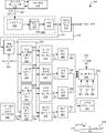
도 2는 본 발명의 다양한 실시예에 따른 사용자 데이터 기반 플라이 하이트 계산 회로를 도시하는 도면.
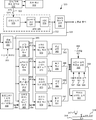
도 3은 본 발명의 다른 실시예에 따른 다른 사용자 데이터 기반 플라이 하이트 계산 회로를 도시하는 도면.
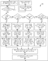
도 4는 사용자 데이터에 기초하여 플라이 하이트를 계산하기 위한 본 발명의 하나 이상의 실시예에 따른 방법을 도시하는 흐름도.
도 5(a)는 본 발명의 하나 이상의 실시예에 따른 사용자 데이터 기반 플라이 하이트 계산 회로를 갖는 판독 채널을 포함하는 저장 디바이스를 도시하는 도면.
도 5(b)는 도 5(a)의 저장 디바이스의 판독/기록 헤드 조립체와 디스크 플래터(platter) 사이의 관계를 도시하는 단면도.1 illustrates an existing storage medium containing servo data.
2 illustrates a user data based fly height calculation circuit in accordance with various embodiments of the present invention.
3 illustrates another user data based fly height calculation circuit in accordance with another embodiment of the present invention.
4 is a flow diagram illustrating a method according to one or more embodiments of the present invention for calculating fly heights based on user data.
5A illustrates a storage device including a read channel having user data based fly height calculation circuitry in accordance with one or more embodiments of the present invention.
FIG. 5 (b) is a cross-sectional view showing the relationship between the read / write head assembly and the disk platter of the storage device of FIG. 5 (a).
본 발명은 저장 매체로 그리고 저장 매체로부터 정보를 전달하기 위한 시스템 및 방법에 관한 것으로서, 더 구체적으로는 저장 매체와 관련하여 센서를 위치시키기 위한 시스템 및 방법에 관한 것이다.The present invention relates to systems and methods for conveying information to and from storage media, and more particularly, to systems and methods for positioning sensors in relation to storage media.
도 1을 참조하면, 저장 매체(100)가 점선으로서 지시된 2개의 예시적인 트랙(150, 155)을 갖고 도시되어 있다. 트랙은 웨지(160, 165) 내에 기록된 서보 데이터에 의해 격리된다. 이들 웨지는 저장 매체(100) 상의 원하는 위치 상에서의 판독/기록 헤드 조립체의 제어 및 동기화를 위해 사용된 서보 데이터(161, 166)를 포함한다. 특히, 이 서보 데이터는 일반적으로 서보 어드레스 마크(SAM)로 이어지는 프리앰블 패턴을 포함한다. 서보 어드레스 마크는 그레이 코드(Gray code)로 이어지고, 그레이 코드는 버스트 정보로 이어진다. 2개의 트랙 및 2개의 웨지가 도시되어 있지만, 각각 수백개의 것들이 소정의 저장 매체 상에 통상적으로 포함될 수 있다는 것이 주목되어야 한다. 또한, 서보 데이터 세트는 버스트 정보의 2개 이상의 필드를 가질 수 있다는 것이 주목되어야 한다. 또한, 예를 들어 버스트 정보 다음에 나타날 수 있는 반복 가능한 런아웃 정보와 같은 상이한 정보가 서보 필드 내에 포함될 수 있다는 것이 주목되어야 한다. 사용자 데이터 영역(180)이 웨지(160, 165) 사이에 배치된다. 사용자 데이터 영역(180)의 각각의 트랙(181)은 각각의 미사용 갭 영역(125, 129)에 의해 각각 분리된 하나 이상의 섹터(123, 127, 131)를 포함한다. 사용자 데이터의 각각의 섹터는 프리앰블(190), 싱크(191), 사용자 데이터 영역(193) 및 섹터 종단 패드(195)를 포함할 수 있다.Referring to FIG. 1,
본 발명의 다양한 실시예는 플라이 하이트 계산을 수행하기 위해 사용자 데이터 영역(181) 내에 주기적인 정보를 이용한다. 플라이 하이트 계산을 수행하기 위해 이러한 데이터를 사용하는 것은 다수의 플라이 하이트 유용 데이터 영역을 제공한다. 본 명세서에 사용될 때, 구문 "플라이 하이트 유용 데이터 영역"은 플라이 하이트를 계산하기 위해 사용될 수 있는 데이터를 포함하는 영역을 의미하는 것으로 가장 넓은 의미에서 사용된다. 몇몇 경우에, 플라이 하이트를 계산하기 위해 사용될 수 있는 데이터는 주기적인 데이터이다. 단지 몇몇 예로서, 플라이 하이트 유용 데이터 영역은 이들에 한정되는 것은 아니지만, 프리앰블(190), 싱크(191), 섹터 종단 패드(195) 및 규정된 기준에 정합하는 데이터(193)의 랜덤 영역을 포함할 수 있다. 몇몇 경우에, 전술된 데이터 영역을 사용하는 것은 플라이 하이트 정확도 계산의 대응 증가를 산출하는 소정의 기간에 걸쳐 평균화하는 증가된 노이즈 감소를 허용하는 플라이 하이트 계산에 대한 종래 기술의 접근법에 비교하여 비교적 큰 데이터의 체적을 제공한다. 대안적으로 또는 게다가, 접근법은 사용자 데이터 영역으로부터의 데이터가 판독될 때 온라인 플라이 하이트 계산을 수행하기 위해 저장 매체로부터 사용자 데이터를 사용하는 것을 허용할 수 있다. 이러한 온라인 플라이 하이트 계산은 저장 매체와 관련하여 수행되는 규칙적인 판독 및 기록 동작을 중단하는 것을 반드시 요구하지는 않는다. 본 명세서에 제공된 설명에 기초하여, 당 기술 분야의 숙련자는 본 발명의 상이한 실시예에 따른 회로, 시스템 및 방법의 구현에 의해 성취될 수 있는 다양한 다른 장점을 인식할 수 있을 것이다. 본 발명의 몇몇 실시예에서, 계산된 플라이 하이트가 개재 서보 웨지의 프로세싱 중에 판독/기록 헤드 조립체의 위치를 업데이트하는데 사용된다. 다양한 경우에, 상이한 가중치가 특정 영역들 사이의 지각된 또는 식별된 신뢰성 차이에 따라 상이한 플라이 하이트 유용 데이터 영역에 기초하여 계산된 플라이 하이트 정보에 인가된다.Various embodiments of the present invention use periodic information in the
도 2를 참조하면, 사용자 데이터 기반 플라이 하이트 계산 회로(200)가 본 발명의 다양한 실시예에 따라 도시된다. 사용자 데이터 기반 플라이 하이트 계산 회로(200)는 특히 서보 웨지 사이로 연장하는 트랙을 따라 저장된 사용자 데이터를 포함하는 저장 매체(212)를 포함한다. 판독/기록 헤드 조립체(210)가 저장 매체(212)와 관련하여 배치되고, 특히 저장 매체(212) 상에 저장된 정보를 감지하고 감지된 정보에 대응하는 판독 데이터 신호(203)를 제공하도록 동작 가능하다. 저장 매체(212)는 다수의 방식으로 포맷될 수 있다. 일 예로서, 저장 매체(212)는 도 1과 관련하여 전술된 것과 유사하게 포맷될 수 있다. 본 명세서에 제공된 설명에 기초하여, 당 기술 분야의 숙련자는 본 발명의 상이한 실시예와 관련하여 사용될 수 있는 다양한 포맷, 저장 매체 및/또는 판독/기록 헤드 조립체를 인식할 수 있을 것이다.2, a user data based fly
판독 데이터 신호(203)가 아날로그 프론트 엔드(front end) 회로(220)에 제공된다. 아날로그 프론트 엔드 회로(220)는 당 기술 분야에 공지된 임의의 아날로그 프론트 엔드 회로일 수 있다. 도시된 바와 같이, 아날로그 프론트 엔드 회로(220)는 전치증폭기 회로(223), 아날로그 필터 회로(226) 및 아날로그-디지털 컨버터 회로(229)를 포함한다. 판독/기록 헤드 조립체(210)로부터의 판독 데이터 신호(203)는 신호를 증폭하고 증폭된 결과를 아날로그 필터 회로(226)에 제공하는 전치증폭기 회로(223)에 의해 수신된다. 아날로그 필터 회로(226)는 수신된 신호를 필터링하고, 대응 필터링된 신호를 아날로그-디지털 컨버터 회로(229)에 제공한다. 아날로그-디지털 컨버터 회로(229)는 수신된 데이터에 대응하는 일련의 디지털 샘플(232)을 제공한다. 본 명세서에 제공된 설명에 기초하여, 당 기술 분야의 숙련자는 본 발명의 상이한 실시예와 관련하여 사용될 수 있는 아날로그-디지털 컨버터 회로(229), 아날로그 필터 회로(226) 및 전치증폭기 회로(223)의 다양한 구현예를 인식할 수 있을 것이다.The read data signal 203 is provided to the analog
디지털 샘플(232)은 검출된 출력(238)을 산출하기 위해 일련의 디지털 샘플(223)에 데이터 검출 알고리즘을 인가하는 데이터 검출기 회로(235)에 제공된다. 이어서, 검출된 출력(238)은 부가의 프로세싱을 위해 다른 하류측 데이터 프로세싱 회로(도시 생략)에 제공될 수 있다. 데이터 검출기 회로(235)는 당 기술 분야에 공지된 데이터 검출 프로세스를 적용하는 것이 가능한 임의의 회로일 수 있다. 본 발명의 일 특정 실시예에서, 데이터 검출기 회로(235)는 비터비 알고리즘(Viterbi algorithm) 데이터 검출기 회로이다. 본 발명의 다른 실시예에서, 데이터 검출기 회로(235)는 최대 사후 데이터 검출기 회로이다. 본 명세서에 제공된 설명에 기초하여, 당 기술 분야의 숙련자는 본 발명의 상이한 실시예와 관련하여 사용될 수 있는 다양한 데이터 검출기 회로를 인식할 수 있을 것이다.The
게다가, 디지털 샘플(232)은 샘플 메모리(250)에 제공되어, 여기서 플라이 하이트를 계산하는 것과 관련하여 가능한 이후의 사용을 위해 유지된다. 샘플 메모리(250)는 사용자 데이터 신호(204)가 어서트(assert)될 때 지시된 바와 같이 사용자 데이터 영역으로부터 데이터로 로딩된다. 사용자 데이터 신호(204)는 사용자/서보 데이터 영역 식별 회로(도시 생략)에 의해 어서트될 수 있다. 검출된 출력(238)은 싱크 마크 패턴 검출기 회로(256), 프리앰블 검출기 회로(259), 섹터 종단 패턴 검출기 회로(262) 및 사용자 데이터 패턴 검출기 회로(265)에 제공된다. 싱크 마크 패턴 검출기 회로(256)는 규정된 싱크 마크 패턴을 위해 검출된 출력(238)을 연속적으로 질의하도록 동작 가능하다. 규정된 싱크 마크 패턴은 이를 "플라이 하이트 유용"하게 하는 소정 레벨의 주기성을 포함하도록 선택된다. 규정된 싱크 마크 패턴이 식별될 때, 싱크 마크 패턴 검출기 회로(256)는 플라이 하이트 계산 회로(270)로의 인에이블 입력(enable input)으로서 동작하는 싱크 마크 발견 출력(257)을 어서트한다. 프리앰블 검출기 회로(259)는 규정된 프리앰블 패턴에 대해 검출된 출력(238)을 연속적으로 질의하도록 동작 가능하다. 규정된 프리앰블 패턴은 이를 "플라이 하이트 유용"하게 하는 소정 레벨의 주기성을 포함하도록 선택된다. 규정된 프리앰블 패턴이 식별될 때, 프리앰블 검출기 회로(259)는 플라이 하이트 계산 회로(273)로의 인에이블 입력으로서 동작하는 프리앰블 발견 출력(260)을 어서트한다. 섹터 종단 패턴 검출기 회로(262)는 규정된 섹터 종단 패턴에 대해 검출된 출력(238)을 연속적으로 질의하도록 동작 가능하다. 규정된 섹터 종단 패턴은 이를 "플라이 하이트 유용"하게 하는 소정 레벨의 주기성을 포함하도록 선택된다. 섹터 종단 패턴이 식별될 때, 섹터 종단 패턴 검출기 회로(262)는 플라이 하이트 계산 회로(276)로의 인에이블 입력으로서 동작하는 섹터 종단 발견 출력(263)을 어서트한다. 사용자 데이터 패턴 검출기 회로(265)는 사용자 데이터 내에 랜덤하게 나타날 수 있는 하나 이상의 규정된 주기적인 패턴에 대해 검출된 출력(238)을 연속적으로 질의하도록 동작 가능하다. 규정된 주기적인 패턴은 프로그램된 사용자 데이터 패턴 메모리(268) 내에 프로그램될 수 있고, 패턴 입력(269)으로서 사용자 데이터 패턴 검출기 회로(265)에 제공된다. 규정된 주기적인 패턴은 이를 "플라이 하이트 유용"하게 하는 소정 레벨의 주기성을 포함하도록 선택된다. 규정된 주기적인 패턴 중 하나가 식별될 때, 사용자 데이터 패턴 검출기 회로(265)는 플라이 하이트 계산 회로(276)로의 인에이블 입력으로서 동작하는 주기적인 패턴 발견 출력(266)을 어서트한다.In addition,
다양한 상이한 플라이 하이트 계산이 패턴 입력(253)에 기초하여 각각의 플라이 하이트 값을 계산하기 위해 플라이 하이트 계산 회로(270), 플라이 하이트 계산 회로(273), 플라이 하이트 계산 회로(276) 및 플라이 하이트 계산 회로(279)에 의해 적용될 수 있다. 본 발명의 일 특정 실시예에서, 플라이 하이트 계산 회로(270), 플라이 하이트 계산 회로(273), 플라이 하이트 계산 회로(276) 및 플라이 하이트 계산 회로(279)의 각각은 주기적인 데이터 입력 및 월러스 간격 손실 이론(Wallace spacing loss theory)에 의존하여 플라이 하이트 계산 알고리즘을 구현한다. 월러스 간격 손실 이론은 임의의 소정의 주파수에서 리드백(readback) 신호 강도가 V(k,d)∝exp(-d,k)에 따라 플라이 하이트의 증가에 따라 지수 함수적으로 감쇠하는 것을 진술하고, 여기서 'd'는 플라이 하이트를 나타내고, 'k'는 주파수를 나타낸다. 이에 따라, 기준 플라이 하이트(d1)로부터의 플라이 하이트의 변화는 이하의 식에 따라 2중 고조파 측정을 사용하여 추정될 수 있고,Various different fly height calculations may be made for the fly height calculation circuit 270, the fly height calculation circuit 273, the fly
![]()
![]()
여기서,here,
{f1, f2} = 고조파 주파수, k=2π/λ{f 1 , f 2 } = harmonic frequency, k = 2π / λ
v = 매체의 선속도v = linear velocity of the medium
ΔR = R2 - R1 = 고조파비의 변화ΔR = R 2 -R 1 = change in harmonic ratio
Δd = d2 - d1 = 플라이 하이트의 변화Δd = d 2 -d 1 = change in fly height

선택된 주파수(f1 및 f2)에서 리드백 신호 강도는 매체 상에 기록된 주기적인 패턴으로부터 측정된다. 패턴은 이것이 고조파로서 이들 주파수의 모두를 포함하도록 선택된다. 플라이 하이트 친화적 패턴의 예는 기간 8T, 10T 및 12T를 갖는 패턴이고, 여기서 'T'는 1 비트의 기간을 나타낸다. 싱크 마크 및 EOS 패드는 임의의 이들(또는 유사한) 패턴에 대응하도록 구성될 수 있다. 8T 패턴의 예는 [+1, +1, +1, +1, -1, -1, -1, -1] 및 [+1, +1, -1, +1, +1, -1, +1, -1]이다. 플라이 하이트 연산을 위해 이용 가능한 데이터 길이를 향상시키기 위해 프리앰블의 적어도 일부를 이용하는 것이 또한 가능하다.The readback signal strength at the selected frequencies f 1 and f 2 is measured from the periodic pattern recorded on the medium. The pattern is chosen so that it contains all of these frequencies as harmonics. An example of a fly height friendly pattern is a pattern with periods 8T, 10T and 12T, where 'T' represents a period of one bit. Sync marks and EOS pads may be configured to correspond to any of these (or similar) patterns. Examples of 8T patterns are [+1, +1, +1, +1, -1, -1, -1, -1] and [+1, +1, -1, +1, +1, -1, +1, -1]. It is also possible to use at least a portion of the preamble to enhance the data length available for fly height operations.
플라이 하이트를 위해 요구되는 고조파 계산은 표준 DFT(이산 푸리에 변환) 연산을 사용하여 수행된다. 이들은 이하의 식에 의해 제공되는데,The harmonic calculations required for fly height are performed using standard Discrete Fourier Transform (DFT) operations. These are provided by the formula

여기서 x[n]은 ADC 출력에서 길이 1 기간의 평균화된 리드백을 나타내고, N은 패턴의 기간의 길이(비트 단위)를 나타내고, ck[n] 및 sk[n]은 DFT 연산을 위해 요구되는 cos 및 sin 커널을 나타낸다. 8T 패턴(즉, N=8)에 대해, 본 출원인은 이하와 같이 제 1 및 제 3 고조파에 대한 커널을 갖는다.Where x [n] represents the averaged readback of a length 1 period at the ADC output, N represents the length (in bits) of the period of the pattern, and ck [n] and sk [n] are required for the DFT operation cos and sin kernels. For the 8T pattern (ie N = 8), we have a kernel for the first and third harmonics as follows.

10T 패턴(즉, N=10)에 대해, 본 출원인은 이하와 같이 제 1 및 제 3 고조파에 대한 커널을 갖는다.For the 10T pattern (i.e., N = 10), we have a kernel for the first and third harmonics as follows.

12T 패턴(즉, N=12)에 대해, 본 출원인은 이하와 같이 제 1 및 제 3 고조파에 대한 커널을 갖는다.For the 12T pattern (ie, N = 12), we have a kernel for the first and third harmonics as follows.

본 발명의 몇몇 실시예에서, 플라이 하이트 계산 회로(270), 플라이 하이트 계산 회로(273), 플라이 하이트 계산 회로(276) 및 플라이 하이트 계산 회로(279)의 각각은 각각 상이하게 구현될 수 있다는 것이 주목되어야 한다. 또한, 전술된 플라이 하이트 계산 회로의 각각은 상이한 길이 입력 패턴[즉 패턴 입력(353)의 각각의 부분]에도 동작할 수 있다는 것이 주목되어야 한다.In some embodiments of the invention, it is noted that each of the fly height calculation circuit 270, the fly height calculation circuit 273, the fly
플라이 하이트 계산 회로(271)는 싱크 마크 패턴에 기초하여 수신된 플라이 하이트 값의 이동 평균이 계산되어 싱크 마크 플라이 하이트 평균(283)으로서 제공되는 경우에 플라이 하이트 값(271)을 평균 회로(282)에 제공한다. 유사하게, 플라이 하이트 계산 회로(273)는 플라이 하이트 값(274)을 평균 회로(285)에 제공하고 여기서 프리앰블 패턴에 기초하여 수신된 플라이 하이트 값의 이동 평균이 계산되어 프리앰블 플라이 하이트 평균(286)으로서 제공되고, 플라이 하이트 계산 회로(276)는 플라이 하이트 값(277)을 평균 회로(288)에 제공하고 여기서 섹터 종단 패턴에 기초하여 수신된 플라이 하이트 값의 이동 평균이 계산되어 섹터 종단 플라이 하이트 평균(289)으로서 제공되고, 플라이 하이트 계산 회로(279)는 플라이 하이트 값(279)을 평균 회로(291)에 제공하고 여기서 사용자 데이터 패턴에 기초하여 수신된 플라이 하이트 값의 이동 평균이 계산되어 사용자 데이터 플라이 하이트 평균(292)으로서 제공된다.The fly
싱크 마크 플라이 하이트 평균(283), 프리앰블 플라이 하이트 평균(286), 섹터 종단 플라이 하이트 평균(289) 및 사용자 데이터 플라이 하이트 평균(292)이 정규화 회로(295)에 제공되고, 여기서 이들은 단일 합성 플라이 하이트 값(202)으로 조합된다. 예를 들어, 모든 4개의 플라이 하이트 값이 조합되는 경우에, 프리앰블 인에이블 신호(296)[프리앰블 플라이 하이트 평균(286)에 대응], 사용자 인에이블 신호(297)[사용자 데이터 플라이 하이트 값(292)에 대응], 섹터 종단 인에이블[섹터 종단 플라이 하이트 평균(289)에 대응] 및 싱크 인에이블(299)[싱크 마크 플라이 하이트 평균(283)에 대응]이 어서트된다. 모든 프리앰블 신호가 어서트되는 경우에, 정규화 회로(295)는 이하의 식에 따라 합성 플라이 하이트 출력(202)을 산출하기 위해 각각의 입력을 동등하게 가중한다.
Sink mark fly
합성 플라이 하이트 출력(202) = (0.25)(싱크마크 플라이 하이트 평균(283)) +Composite Fly Height Output (202) = (0.25) (Sinkmark Fly Height Average (283)) +
(0.25)(프리앰블 플라이 하이트 평균(286)) +(0.25) (Preamble Fly Height Average (286)) +
(0.25)(섹터 종단 플라이 하이트 평균(289)) +(0.25) (sector end fly height average (289)) +
(0.25)(사용자 데이터 플라이 하이트 평균(292))(0.25) (User Data Fly Height Average (292))
대안적으로, 4개의 인에이블 중 단지 3개만이 어서트되는 경우에, 정규화 회로(295)는 대응하는 3개의 평균 출력을 합성 플라이 하이트 출력(202)에 조합하고, 어서트되지 않은 인에이블에 대응하는 평균을 배제한다. 예를 들어, 사용자 인에이블 신호(297)가 어서트되지 않고 다른 3개의 인에이블은 어서트되는 경우에, 정규화 회로(295)는 이하의 식에 따라 합성 플라이 하이트 출력(202)을 제공한다.
Alternatively, if only three of the four enable are asserted, the
합성 플라이 하이트 출력(202) = (0.33)(싱크마크 플라이 하이트 평균(283)) +Composite Fly Height Output (202) = (0.33) (Sinkmark Fly Height Average (283)) +
(0.33)(프리앰블 플라이 하이트 평균(286)) +(0.33) (Preamble Fly Height Average (286)) +
(0.33)(섹터 종단 플라이 하이트 평균(289))
(0.33) (sector end fly height average (289))
대안적으로, 4개의 인에이블 중 단지 2개만이 어서트되는 경우에, 정규화 회로(295)는 인에이블링되는 2개의 평균 출력을 합성 플라이 하이트 출력(202)에 조합하고, 어서트되지 않은 인에이블에 대응하는 평균을 배제한다. 예를 들어, 사용자 인에이블 신호(297) 및 프리앰블 인에이블 신호(296)가 어서트되지 않고 다른 2개의 인에이블은 어서트되는 경우에, 정규화 회로(295)는 이하의 식에 따라 합성 플라이 하이트 출력(202)을 제공한다.
Alternatively, if only two of the four enable are asserted, the
합성 플라이 하이트 출력(202) = (0.50)(싱크 마크 플라이 하이트 평균(283)) +Composite Fly Height Output (202) = (0.50) (Sink Mark Fly Height Average (283)) +
(0.50)(섹터 종단 플라이 하이트 평균(289))
(0.50) (sector end fly height average (289))
대안적으로, 4개의 인에이블 중 단지 하나가 어서트되는 경우에, 정규화 회로(295)는 합성 플라이 하이트 출력(202)으로서 어서트된 인에이블에 대응하는 평균 출력을 제공하고, 어서트되지 않은 3개의 인에이블에 대응하는 평균을 배제한다.Alternatively, if only one of the four enable is asserted,
결과적인 합성 플라이 하이트 출력(202)은 합성 플라이 하이트 출력(202)의 크기 및 부호에 따라 판독/기록 헤드 조립체(217)와 대응 저장 매체(218) 사이의 거리(216)(플라이 하이트)를 조정하도록 동작 가능한 플라이 하이트 조정 회로(201)에 제공된다. 플라이 하이트 조정 회로(201)는 플라이 하이트를 조정하는 것이 가능한 당 기술 분야에 공지된 임의의 회로일 수 있다.The resulting composite
이제 도 3을 참조하면, 다른 사용자 데이터 기반 플라이 하이트 계산 회로(300)가 본 발명의 다른 실시예에 따라 도시되어 있다. 사용자 데이터 기반 플라이 하이트 계산 회로(300)는 특히 서보 웨지들 사이로 연장하는 트랙을 따라 저장된 사용자 데이터를 포함하는 저장 매체(312)를 포함한다. 판독/기록 헤드 조립체(310)가 저장 매체(312)에 관련하여 배치되고, 특히 저장 매체(312) 상에 저장된 정보를 감지하고 감지된 정보에 대응하는 판독 데이터 신호(303)를 제공하도록 동작 가능하다. 저장 매체(312)는 다수의 방식으로 포맷될 수 있다. 일 예로서, 저장 매체(312)는 도 1에 관련하여 전술된 바와 유사하게 포맷될 수 있다. 본 명세서에 제공된 설명에 기초하여, 당 기술 분야의 숙련자는 본 발명의 상이한 실시예에 관련하여 사용될 수 있는 다양한 포맷, 저장 매체 및/또는 판독/기록 헤드 조립체를 인식할 수 있을 것이다.Referring now to FIG. 3, another user data based fly
판독 데이터 신호(303)는 아날로그 프론트 엔드 회로(320)에 제공된다. 아날로그 프론트 엔드 회로(320)는 당 기술 분야에 공지된 임의의 아날로그 프론트 엔드 회로일 수 있다. 도시된 바와 같이, 아날로그 프론트 엔드 회로(320)는 전치증폭기 회로(323), 아날로그 필터 회로(326) 및 아날로그-디지털 컨버터 회로(329)를 포함한다. 판독/기록 헤드 조립체(310)로부터의 판독 데이터 신호(303)는 신호를 증폭하고 증폭된 결과를 아날로그 필터 회로(326)에 제공하는 전치증폭기 회로(323)에 의해 수신된다. 아날로그 필터 회로(326)가 수신된 신호를 필터링하고 대응 필터링된 신호를 아날로그-디지털 컨버터 회로(329)에 제공한다. 아날로그-디지털 컨버터 회로(329)는 수신된 데이터에 대응하는 일련의 디지털 샘플(332)을 제공한다. 본 명세서에 제공된 설명에 기초하여, 당 기술 분야의 숙련자는 본 발명의 상이한 실시예에 관련하여 사용될 수 있는 아날로그-디지털 컨버터 회로(329), 아날로그 필터 회로(326) 및 전치증폭기 회로(323)의 다양한 구현을 인식할 수 있을 것이다.The read data signal 303 is provided to the analog
디지털 샘플(332)은 검출된 출력(338)을 산출하기 위해 일련의 디지털 샘플(323)에 데이터 검출 알고리즘을 적용하는 데이터 검출기 회로(335)에 제공된다. 이어서, 검출된 출력(338)은 부가의 프로세싱을 위해 다른 하류측 데이터 프로세싱 회로(도시 생략)에 제공될 수 있다. 데이터 검출기 회로(335)는 당 기술 분야에 공지된 데이터 검출 프로세스를 적용하는 것이 가능한 임의의 회로일 수 있다. 본 발명의 일 특정 실시예에서, 데이터 검출기 회로(335)는 비터비 알고리즘 데이터 검출기 회로이다. 본 발명의 다른 실시예에서, 데이터 검출기 회로(335)는 최대 사후 데이터 검출기 회로이다. 본 발명에 제공된 설명에 기초하여, 당 기술 분야의 숙련자는 본 발명의 상이한 실시예에 관련하여 사용될 수 있는 다양한 데이터 검출기 회로를 인식할 수 있을 것이다.The
게다가, 디지털 샘플(332)이 샘플 메모리(350)에 제공되고, 여기서 이들은 플라이 하이트를 계산하는 것과 관련하여 가능한 이후의 사용을 위해 유지된다. 샘플 메모리(350)는 사용자 데이터 신호(304)가 어서트될 때 지시된 바와 같이 사용자 데이터 영역으로부터 데이터로 로딩된다. 사용자 데이터 신호(304)는 사용자/서보 데이터 영역 식별 회로(도시 생략)에 의해 어서트될 수 있다. 검출된 출력(338)은 싱크 마크 패턴 검출기 회로(356), 프리앰블 검출기 회로(359), 섹터 종단 패턴 검출기 회로(362) 및 사용자 데이터 패턴 검출기 회로(365)에 제공된다. 싱크 마크 패턴 검출기 회로(356)는 규정된 싱크 마크 패턴을 위한 검출된 출력(338)을 연속적으로 질의하도록 동작 가능하다. 규정된 싱크 마크 패턴은 이를 "플라이 하이트 유용"하게 하는 소정 레벨의 주기성을 포함하도록 선택된다. 규정된 싱크 마크 패턴이 식별될 때, 싱크 마크 패턴 검출기 회로(356)는 플라이 하이트 계산 회로(370)로의 인에이블 입력으로서 동작하는 싱크 마크 발견 출력(357)을 어서트한다. 프리앰블 검출기 회로(359)는 규정된 프리앰블 패턴을 위한 검출된 출력(338)을 연속적으로 질의하도록 동작 가능하다. 규정된 프리앰블 패턴은 이를 "플라이 하이트 유용"하게 하는 소정 레벨의 주기성을 포함하도록 선택된다. 규정된 프리앰블 패턴이 식별될 때, 프리앰블 검출기 회로(359)는 플라이 하이트 계산 회로(373)로의 인에이블 입력으로서 동작하는 프리앰블 발견 출력(360)을 어서트한다. 섹터 종단 패턴 검출기 회로(362)는 규정된 섹터 종단 패턴을 위한 검출된 출력(338)을 연속적으로 질의하도록 동작 가능하다. 규정된 섹터 종단 패턴은 이를 "플라이 하이트 유용"하게 하는 소정 레벨의 주기성을 포함하도록 선택된다. 규정된 섹터 종단 패턴이 식별될 때, 섹터 종단 검출기 회로(362)는 플라이 하이트 계산 회로(376)로의 인에이블 입력으로서 동작하는 섹터 종단 발견 출력(363)을 어서트한다. 사용자 데이터 패턴 검출기 회로(365)는 사용자 데이터 내에 랜덤하게 나타날 수 있는 하나 이상의 규정된 주기적인 패턴을 위한 검출된 출력(338)을 연속적으로 질의하도록 동작 가능하다. 규정된 주기적인 패턴은 프로그램된 사용자 데이터 패턴 메모리(368) 내로 프로그램될 수 있고, 패턴 입력(369)으로서 사용자 데이터 패턴 검출기 회로(365)에 제공된다. 규정된 주기적인 패턴은 이를 "플라이 하이트 유용"하게 하는 소정 레벨의 주기성을 각각 포함하도록 선택된다. 규정된 주기적인 패턴 중 하나가 식별될 때, 사용자 패턴 검출기 회로(365)는 플라이 하이트 계산 회로(376)로의 인에이블 입력으로서 동작하는 주기적인 패턴 발견 출력(366)을 어서트한다. In addition,
다양한 상이한 플라이 하이트 계산이 패턴 입력(353)에 기초하여 각각의 플라이 하이트 값을 계산하기 위해 플라이 하이트 계산 회로(370), 플라이 하이트 계산 회로(373), 플라이 하이트 계산 회로(376) 및 플라이 하이트 계산 회로(379)에 의해 적용될 수 있다. 본 발명의 일 특정 실시예에서, 플라이 하이트 계산 회로(370), 플라이 하이트 계산 회로(373), 플라이 하이트 계산 회로(376) 및 플라이 하이트 계산 회로(379)의 각각은 주기적인 데이터 입력 및 월러스 간격 손실 이론에 의존하여 플라이 하이트 계산 알고리즘을 구현한다. 월러스 간격 손실 이론은 임의의 소정의 주파수에서 리드백 신호 강도가 V(k,d)∝exp(-d,k)에 따라 플라이 하이트의 증가에 따라 지수 함수적으로 감쇠하는 것을 진술하고, 여기서 'd'는 플라이 하이트를 나타내고, 'k'는 주파수를 나타낸다. 이에 따라, 기준 플라이 하이트(d1)로부터의 플라이 하이트의 변화는 이하의 식에 따라 2중 고조파 측정을 사용하여 추정될 수 있고,Various different fly height calculations may be made for the fly height calculation circuit 370, the fly height calculation circuit 373, the fly
![]()
![]()
여기서,here,
{f1, f2} = 고조파 주파수, k=2π/λ{f 1 , f 2 } = harmonic frequency, k = 2π / λ
v = 매체의 선속도v = linear velocity of the medium
ΔR = R2 - R1 = 고조파비의 변화ΔR = R 2 -R 1 = change in harmonic ratio
Δd = d2 - d1 = 플라이 하이트의 변화Δd = d 2 -d 1 = change in fly height
선택된 주파수(f1 및 f2)에서 리드백 신호 강도는 매체 상에 기록된 주기적인 패턴으로부터 측정된다. 패턴은 이것이 고조파로서 이들 주파수의 모두를 포함하도록 선택된다. 플라이 하이트 친화적 패턴의 예는 기간 8T, 10T 및 12T를 갖는 패턴이고, 여기서 'T'는 1 비트의 기간을 나타낸다. 싱크 마크 및 EOS 패드는 임의의 이들(또는 유사한) 패턴에 대응하도록 구성될 수 있다. 8T 패턴의 예는 [+1, +1, +1, +1, -1, -1, -1, -1] 및 [+1, +1, -1, +1, +1, -1, +1, -1]이다. 플라이 하이트 연산을 위해 이용 가능한 데이터 길이를 향상시키기 위해 프리앰블의 적어도 일부를 이용하는 것이 또한 가능하다.The readback signal strength at the selected frequencies f 1 and f 2 is measured from the periodic pattern recorded on the medium. The pattern is chosen so that it contains all of these frequencies as harmonics. An example of a fly height friendly pattern is a pattern with periods 8T, 10T and 12T, where 'T' represents a period of one bit. Sync marks and EOS pads may be configured to correspond to any of these (or similar) patterns. Examples of 8T patterns are [+1, +1, +1, +1, -1, -1, -1, -1] and [+1, +1, -1, +1, +1, -1, +1, -1]. It is also possible to use at least a portion of the preamble to enhance the data length available for fly height operations.
플라이 하이트를 위해 요구되는 고조파 계산은 표준 DFT(이산 푸리에 변환) 연산을 사용하여 수행된다. 이들은 이하의 식에 의해 제공되는데,The harmonic calculations required for fly height are performed using standard Discrete Fourier Transform (DFT) operations. These are provided by the formula

여기서 x[n]은 ADC 출력에서 길이 1 기간의 평균화된 리드백을 나타내고, N은 패턴의 기간의 길이(비트 단위)를 나타내고, ck[n] 및 sk[n]은 DFT 연산을 위해 요구되는 cos 및 sin 커널을 나타낸다. 8T 패턴(즉, N=8)에 대해, 본 출원인은 이하와 같이 제 1 및 제 3 고조파에 대한 커널을 갖는다.Where x [n] represents the averaged readback of a length 1 period at the ADC output, N represents the length (in bits) of the period of the pattern, and ck [n] and sk [n] are required for the DFT operation cos and sin kernels. For the 8T pattern (ie N = 8), we have a kernel for the first and third harmonics as follows.

10T 패턴(즉, N=10)에 대해, 본 출원인은 이하와 같이 제 1 및 제 3 고조파에 대한 커널을 갖는다.For the 10T pattern (i.e., N = 10), we have a kernel for the first and third harmonics as follows.

12T 패턴(즉, N=12)에 대해, 본 출원인은 이하와 같이 제 1 및 제 3 고조파에 대한 커널을 갖는다.For the 12T pattern (ie, N = 12), we have a kernel for the first and third harmonics as follows.

본 발명의 몇몇 실시예에서, 플라이 하이트 계산 회로(370), 플라이 하이트 계산 회로(373), 플라이 하이트 계산 회로(376) 및 플라이 하이트 계산 회로(379)의 각각은 각각 상이하게 구현될 수 있다는 것이 주목되어야 한다. 또한, 전술된 플라이 하이트 계산 회로의 각각은 상이한 길이 입력 패턴[즉 패턴 입력(353)의 각각의 부분]에도 동작할 수 있다는 것이 주목되어야 한다.In some embodiments of the present invention, it is understood that each of the fly height calculation circuit 370, the fly height calculation circuit 373, the fly
플라이 하이트 계산 회로(371)는 플라이 하이트 값(371)을 평균 회로(382)에 제공하고, 여기서 싱크 마크 패턴에 기초하는 수신된 플라이 하이트 값의 이동 평균이 계산되고 싱크 마크 플라이 하이트 평균(383)으로서 제공된다. 유사하게, 플라이 하이트 계산 회로(373)는 플라이 하이트 값(374)을 평균 회로(385)에 제공하고, 여기서 프리앰블 패턴에 기초하는 수신된 플라이 하이트 값의 이동 평균이 계산되고 프리앰블 플라이 하이트 평균(386)으로서 제공되고, 플라이 하이트 계산 회로(376)는 플라이 하이트 값(377)을 평균 회로(388)에 제공하고, 여기서 섹터 종단 패턴에 기초하여 수신된 플라이 하이트 값의 이동 평균이 계산되어 섹터 종단 플라이 하이트 평균(389)으로서 제공되고, 플라이 하이트 계산 회로(379)는 플라이 하이트 값(379)을 평균 회로(391)에 제공하고, 여기서 사용자 데이터 패턴에 기초하여 수신된 플라이 하이트 값의 이동 평균이 계산되어 사용자 데이터 플라이 하이트 평균(392)으로서 제공된다.The fly
싱크 마크 플라이 하이트 평균(383), 프리앰블 플라이 하이트 평균(386), 섹터 종단 플라이 하이트 평균(389) 및 사용자 데이터 플라이 하이트 평균(392)이 정규화 회로(395)에 제공되고 여기서 이들은 이하의 식에 따라 입력 가중치[프리앰블 플라이 하이트 평균(386)에 대응하는 프리앰블 WT(396), 사용자 데이터 플라이 하이트 평균(392)에 대응하는 사용자 WT(397), 섹터 종단 플라이 하이트 평균(389)에 대응하는 섹터 종단 WT(398) 및 싱크 마크 플라이 하이트 평균(383)에 대응하는 싱크 WT(399)]를 사용하여 단일 합성 플라이 하이트 값(302) 내에 조합된다.
Sink mark fly
합성 플라이 하이트 출력(302) = Composite Fly Height Output (302) =
(싱크 WT(399))(싱크 마크 플라이 하이트 평균(383)) +(Sink WT (399)) (sink mark fly height average (383)) +
(프리앰블 WT(396))(프리앰블 플라이 하이트 평균(386)) +(Preamble WT (396)) (Preamble Fly Height Average (386)) +
(섹터 종단 WT(398))(섹터 종단 플라이 하이트 평균(389)) +(Sector Termination WT (398)) (Sector Termination Fly Height Average (389)) +
(사용자 WT(397))(사용자 데이터 플라이 하이트 평균(392))
(User WT (397)) (User Data Fly Height Average (392))
몇몇 실시예에서, 프리앰블 WT(396), 사용자 WT(397), 섹터 종단 WT(398) 및 싱크 WT(399)의 합은 1이다.In some embodiments, the sum of the
결과적인 합성 플라이 하이트 출력(302)은 합성 플라이 하이트 출력(302)의 크기 및 부호에 따라 판독/기록 헤드 조립체(317)와 대응 저장 매체(318) 사이의 거리(316)(플라이 하이트)를 조정하도록 동작 가능한 플라이 하이트 조정 회로(301)에 제공된다. 플라이 하이트 조정 회로(301)는 플라이 하이트를 조정하는 것이 가능한 당 기술 분야에 공지된 임의의 회로일 수 있다.The resulting composite
이제 도 4를 참조하면, 흐름도(400)는 사용자 데이터에 기초하는 플라이 하이트를 계산하기 위한 본 발명의 하나 이상의 실시예에 따른 방법을 도시한다. 흐름도(400)에 따라, 아날로그 입력이 연속적으로 수신된다(블록 405). 몇몇 경우에, 이 아날로그 신호는 저장 매체로부터 수신된 아날로그 프론트 엔드 회로 프로세싱 정보로부터 수신된다. 아날로그 입력은 아날로그-디지털 컨버터 회로에 의해 일련의 디지털 샘플로 변환된다(블록 410). 일련의 디지털 샘플로의 변환은 당 기술 분야에 공지된 임의의 아날로그-디지털 변환 방법을 사용하여 행해질 수 있다. 데이터 프로세싱은 데이터 출력을 산출하기 위해 일련의 디지털 샘플에 적용된다(블록 415). 몇몇 경우에, 이 데이터 프로세싱은 예를 들어 최대 사후 데이터 검출 프로세스 또는 비터비 알고리즘 데이터 검출 프로세스와 같은 당 기술 분야에 공지된 데이터 검출 프로세스일 수 있다. 본 명세서에 제공된 설명에 기초하여, 당 기술 분야의 숙련자는 본 발명의 상이한 실시예에 관련하여 사용될 수 있는 다양한 데이터 검출 프로세스를 인식할 수 있을 것이다.Referring now to FIG. 4, a
사용자 데이터 영역(즉, 2개의 서보 데이터 웨지 사이의 영역)이 프로세싱 중인지 여부가 판정된다(블록 418). 사용자 데이터 영역이 프로세싱 중이면(블록 418), 사용자 데이터의 하나 이상의 섹터와 연관된 프리앰블이 발견되었는지 여부가 판정된다(블록 420). 프리앰블이 발견되는 경우에(블록 420), 식별된 프리앰블에 대응하는 수신된 디지털 샘플이 식별된다(블록 425). 이들 식별된 디지털 샘플은 프리앰블에 기초하여 플라이 하이트 값을 계산하는데 사용된다(블록 430). 플라이 하이트는 당 기술 분야에 공지된 임의의 플라이 하이트 계산 알고리즘을 사용하여 계산될 수 있다. 프리앰블에 기초하는 계산된 플라이 하이트는 평균화된 프리앰블 플라이 하이트를 산출하기 위해 다른 유사한 플라이 하이트의 이동 평균 내에 통합된다(블록 435).It is determined whether the user data area (ie, the area between two servo data wedges) is being processed (block 418). If the user data area is being processed (block 418), it is determined whether a preamble associated with one or more sectors of user data has been found (block 420). If a preamble is found (block 420), the received digital sample corresponding to the identified preamble is identified (block 425). These identified digital samples are used to calculate fly height values based on the preamble (block 430). Fly heights can be calculated using any fly height calculation algorithm known in the art. The calculated fly height based on the preamble is integrated into the moving average of other similar fly heights to yield the averaged preamble fly height (block 435).
대안적으로, 프리앰블이 발견되지 않으면(블록 420), 사용자 데이터의 하나 이상의 섹터와 연관된 사용자 싱크 마크가 발견되었는지 여부가 판정된다(블록 440). 사용자 싱크 마크가 발견되는 경우에(블록 440), 식별된 사용자 싱크 마크에 대응하는 수신된 디지털 샘플이 식별된다(블록 445). 이들 식별된 디지털 샘플은 사용자 싱크 마크에 기초하여 플라이 하이트 값을 계산하는데 사용된다(블록 450). 플라이 하이트는 당 기술 분야에 공지된 임의의 플라이 하이트 계산 알고리즘을 사용하여 계산될 수 있다. 사용자 싱크 마크에 기초하는 계산된 플라이 하이트는 평균화된 싱크 마크 플라이 하이트를 산출하기 위해 다른 유사한 플라이 하이트 값의 이동 평균 내로 통합된다(블록 455).Alternatively, if no preamble is found (block 420), it is determined whether a user sync mark associated with one or more sectors of user data has been found (block 440). If a user sink mark is found (block 440), the received digital sample corresponding to the identified user sink mark is identified (block 445). These identified digital samples are used to calculate fly height values based on user sync marks (block 450). Fly heights can be calculated using any fly height calculation algorithm known in the art. The calculated fly height based on the user sync mark is incorporated into a moving average of other similar fly height values to yield an averaged sync mark fly height (block 455).
대안적으로, 프리앰블이 발견되지 않으면(블록 460), 사용자 데이터의 하나 이상의 섹터와 연관된 섹터 종단 마크가 발견되었는지 여부가 판정된다(블록 460). 섹터 종단 마크가 발견되는 경우에(블록 460), 식별된 섹터 종단 마크에 대응하는 수신된 디지털 샘플이 식별된다(블록 465). 이들 식별된 디지털 샘플은 섹터 종단 마크에 기초하여 플라이 하이트 값을 계산하는데 사용된다(블록 470). 플라이 하이트는 당 기술 분야에 공지된 임의의 플라이 하이트 계산 알고리즘을 사용하여 계산될 수 있다. 섹터 종단 마크에 기초하여 계산된 플라이 하이트는 평균화된 섹터 종단 플라이 하이트를 산출하기 위해 다른 유사한 플라이 하이트 값의 이동 평균 내에 통합된다(블록 475).Alternatively, if a preamble is not found (block 460), it is determined whether a sector end mark associated with one or more sectors of user data has been found (block 460). If a sector end mark is found (block 460), then the received digital sample corresponding to the identified sector end mark is identified (block 465). These identified digital samples are used to calculate fly height values based on sector termination marks (block 470). Fly heights can be calculated using any fly height calculation algorithm known in the art. The fly height calculated based on the sector end mark is integrated into a moving average of other similar fly height values to yield an averaged sector end fly height (block 475).
대안적으로, 섹터 종단 마크가 발견되지 않는 경우에(블록 460), 사용자 데이터 내의 사전결정된 패턴이 발견되었는지 여부가 판정된다(블록 480). 이러한 사전결정된 패턴이 발견되는 경우에(블록 480), 식별된 사전결정된 패턴에 대응하는 수신된 디지털 샘플이 식별된다(블록 485). 이들 식별된 디지털 샘플은 사전결정된 패턴에 기초하여 플라이 하이트 값을 계산하는데 사용된다(블록 490). 플라이 하이트는 당 기술 분야에 공지된 임의의 플라이 하이트 계산 알고리즘을 사용하여 계산될 수 있다. 사용자 싱크 마크에 기초하는 계산된 플라이 하이트는 평균화된 사용자 데이터 패턴 플라이 하이트를 산출하기 위해 다른 유사한 플라이 하이트 값의 이동 평균 내에 통합된다(블록 495).Alternatively, if no sector end mark is found (block 460), it is determined whether a predetermined pattern in the user data has been found (block 480). If such a predetermined pattern is found (block 480), then the received digital sample corresponding to the identified predetermined pattern is identified (block 485). These identified digital samples are used to calculate fly height values based on the predetermined pattern (block 490). Fly heights can be calculated using any fly height calculation algorithm known in the art. The calculated fly height based on the user sync mark is incorporated into a moving average of other similar fly height values to yield an averaged user data pattern fly height (block 495).
평균화된 프리앰블 플라이 하이트, 평균화된 사용자 싱크 플라이 하이트, 평균화된 섹터 종단 플라이 하이트 및 평균화된 사용자 데이터 플라이 하이트는 합성 플라이 하이트 값을 산출하도록 가중된 정규화를 수행하는데 사용된다(블록 401). 몇몇 경우에, 합성 값은 이하의 식에 따라 계산된다.
The averaged preamble fly height, averaged user sink fly height, averaged sector end fly height and averaged user data fly height are used to perform weighted normalization to yield a composite fly height value (block 401). In some cases, the composite value is calculated according to the following formula.
합성 플라이 하이트 출력 =Composite Fly Height Output =
(싱크 마크 가중치)(평균화된 싱크 마크) +(Sink Mark Weight) (Averaged Sync Mark) +
(프리앰블 가중치)(평균화된 프리앰블 플라이 하이트) +(Preamble weight) (averaged preamble fly height) +
(섹터 종단 가중치)(평균화된 섹터 종단 플라이 하이트) +Sector End Weights (Averaged Sector End Fly Heights) +
(사용자 데이터 가중치)(평균화된 사용자 데이터 플라이 하이트)
(User Data Weight) (Averaged User Data Fly Heights)
몇몇 실시예에서, 싱크 마크 가중치, 프리앰블 가중치, 사용자 데이터 가중치, 섹터 종단 가중치 및 사용자 데이터 가중치는 프로그램 가능 가중 팩터이고, 몇몇 경우에 4개의 가중 팩터의 합은 1이다. 합성 플라이 하이트 값은 이어서 플라이 하이트를 수정하는데 사용된다(블록 402).In some embodiments, the sync mark weights, preamble weights, user data weights, sector end weights, and user data weights are programmable weight factors, and in some cases the sum of the four weight factors is one. The synthetic fly height value is then used to modify the fly height (block 402).
도 5(a)를 참조하면, 사용자 데이터 기반 플라이 하이트 계산 회로를 갖는 판독 채널 회로(510)를 포함하는 저장 디바이스(500)가 본 발명의 하나 이상의 실시예에 따라 도시되어 있다. 저장 디바이스(500)는 예를 들어 하드 디스크 드라이브일 수 있다. 또한, 판독 채널 회로(510)는 예를 들어 비터비 알고리즘 데이터 검출기와 같은 데이터 검출기 및/또는 예를 들어 저밀도 패리티 검사 디코더 회로와 같은 데이터 디코더 회로를 포함할 수 있다. 판독 채널 회로(510)에 추가하여, 저장 디바이스(500)는 디스크 플래터(578)와 관련하여 배치된 판독/기록 헤드 조립체(576)를 포함한다. 판독/기록 헤드 조립체(576)는 디스크 플래터(578) 상에 저장된 정보를 감지하고 대응 전기 신호를 판독 채널 회로(510)에 제공하도록 동작 가능하다.Referring to FIG. 5A, a
저장 디바이스(500)는 인터페이스 제어기(520), 하드 디스크 제어기(566), 모터 제어기 및 플라이 하이트 제어기(568) 및 스핀들 모터(572)를 또한 포함한다. 인터페이스 제어기(520)는 디스크 플래터(578)로/로부터의 데이터의 어드레싱 및 타이밍을 제어한다. 디스크 플래터(578) 상의 데이터는 조립체가 디스크 플래터(578) 상에 적절하게 위치될 때 판독/기록 헤드 조립체(576)에 의해 검출될 수 있는 자기 신호의 그룹으로 이루어진다. 일 실시예에서, 디스크 플래터(578)는 수직 기록 체계에 따라 기록된 자기 신호를 포함한다. 본 발명의 다른 실시예에서, 디스크 플래터(578)는 종방향 기록 체계에 따라 기록된 자기 신호를 포함한다. 모터 제어기 및 플라이 하이트 제어기(568)는 디스크 플래터(578)에 관련하여 디스크 플래터(578)의 스핀 속도 및 판독/기록 헤드 조립체(576)의 위치를 제어한다.
도 5(b)의 단면도(491)에 도시되어 있는 바와 같이, 판독/기록 헤드 조립체(576)와 디스크 플래터(578) 사이의 거리는 플라이 하이트(590)이다. 플라이 하이트(590)는 판독 채널 회로(510)에 의해 제공된 고조파 값(512)에 기초하여 모터 제어기 및 플라이 하이트 제어기(568)에 의해 제어된다.As shown in cross-sectional view 491 of FIG. 5B, the distance between the read /
통상의 판독 동작에서, 판독/기록 헤드 조립체(576)는 디스크 플래터(578) 상의 원하는 데이터 트랙 상에 모터 제어기 및 플라이 하이트 제어기(568)에 의해 정확하게 위치된다. 모터 제어기 및 플라이 하이트 제어기(568)는 모두 디스크 플래터(578)와 관련하여 판독/기록 헤드 조립체(576)를 위치시키고(측방향으로 및 수직으로), 하드 디스크 제어기(566)의 지시 하에서 디스크 플래터(578) 상의 적절한 데이터 트랙으로 판독/기록 헤드 조립체(576)를 이동시킴으로써 스핀들 모터(572)를 구동한다. 스핀들 모터(572)는 사전결정된 스핀 속도(RPM)에서 디스크 플래터(578)를 스핀한다. 일단 판독/기록 헤드 조립체(578)가 적절한 데이터 트랙에 인접하여 위치되면, 스핀들 모터(572)에 의해 회전함에 따라 디스크 플래터(578) 상의 데이터를 표현하는 자기 신호가 디스크 플래터(578)가 판독/기록 헤드 조립체(576)에 의해 감지된다. 감지된 자기 신호는 디스크 플래터(578) 상의 자기 데이터를 표현하는 연속적인 정밀한 아날로그 신호로서 제공된다. 이 정밀한 아날로그 신호는 채널 회로(510)를 판독하기 위해 판독/기록 헤드 조립체(576)에 의해 제공된다. 이어서, 판독 채널 회로(510)는 디스크 플래터(578)에 원래 기록된 정보를 재생성하기 위해 수신된 아날로그 신호를 디코딩하고 디지털화한다. 이 데이터는 판독 데이터(503)로서 수신 회로에 제공된다. 기록 동작은 실질적으로 채널 회로(510)를 판독하도록 제공되는 기록 데이터(501)를 갖는 이전의 판독 동작과 반대이다. 이 데이터는 이어서 인코딩되어 디스크 플래터(578)에 기록된다.In a typical read operation, read /
때때로, 디스크 플래터(578)로부터 유도된 신호는 플라이 하이트를 결정하도록 프로세싱될 수 있다. 본 발명의 몇몇 실시예에서, 플라이 하이트를 결정하는 것은 도 4에 관련하여 전술된 방법에 따라 행해질 수 있다. 다양한 경우에, 상기 도 2 또는 도 3에 관련하여 설명된 바에 따른 회로는 사용자 데이터 기반 플라이 하이트 계산을 수행하는데 사용될 수 있다. 다양한 경우에, 플라이 하이트는 저장 디바이스(500)의 동작 상태의 변화가 검출될 때 재평가된다. 이러한 동작 변화는 이들에 한정되는 것은 아니지만, 동작 전압 레벨의 변화, 동작 온도의 변화, 고도의 변화 또는 비트 에러율의 변화를 포함할 수 있다. 본 명세서에 제공된 설명에 기초하여, 당 기술 분야의 숙련자는 저장 디바이스(500) 내에서 모니터링될 수 있는 다양한 동작 상태 및 이러한 상태의 변화가 어떻게 플라이 하이트의 재평가를 트리거링하는데 이용될 수 있는지를 인식할 수 있을 것이다.At times, the signal derived from
저장 시스템(500)은 예를 들어, RAID(중복 어레이 저가 디스크 또는 중복 어레이 독립 디스크) 기반 저장 시스템과 같은 더 대형 저장 시스템 내에 일체화될 수 있다는 것이 주목되어야 한다. 저장 시스템(500)의 다양한 기능 또는 블록은 소프트웨어 또는 펌웨어로 구현될 수 있고, 다른 기능 또는 블록들은 하드웨어로 구현될 수 있다는 것이 또한 주목되어야 한다.It should be noted that the
상기 용례에 설명된 다양한 블록은 다른 기능성과 함께 집적 회로 내에 구현될 수 있다는 것이 주목되어야 한다. 이러한 집적 회로는 소정의 블록, 시스템 또는 회로의 모든 기능 또는 단지 블록, 시스템 또는 회로의 서브세트만을 포함할 수 있다. 또한, 블록, 시스템 또는 회로의 요소는 다수의 집적 회로를 가로질러 구현될 수도 있다. 이러한 집적 회로는 이들에 한정되는 것은 아니지만, 모노리식 집적 회로, 플립 칩 집적 회로, 멀티칩 모듈 집적 회로 및/또는 혼합 신호 집적 회로를 포함하는 당 기술 분야에 공지된 임의의 유형의 집적 회로일 수 있다. 본 명세서에 설명된 블록, 시스템 또는 회로의 다양한 기능은 소프트웨어 또는 펌웨어로 구현될 수 있다는 것이 또한 주목되어야 한다. 몇몇 이러한 경우에, 전체 시스템, 블록 또는 회로는 그 소프트웨어 또는 펌웨어 등가물을 사용하여 구현될 수 있다. 다른 경우에, 소정의 시스템, 블록 또는 회로 중 일 부분은 소프트웨어 또는 펌웨어로 구현될 수 있고, 다른 부분들은 하드웨어로 구현될 수 있다.It should be noted that the various blocks described in the above application may be implemented in an integrated circuit with other functionality. Such integrated circuits may include all the functionality of a given block, system or circuit or only a subset of the block, system or circuit. In addition, elements of a block, system, or circuit may be implemented across multiple integrated circuits. Such integrated circuits may be any type of integrated circuits known in the art, including but not limited to monolithic integrated circuits, flip chip integrated circuits, multichip module integrated circuits, and / or mixed signal integrated circuits. have. It should also be noted that various functions of the blocks, systems or circuits described herein may be implemented in software or firmware. In some such cases, the entire system, block or circuit may be implemented using its software or firmware equivalents. In other cases, one portion of a given system, block, or circuit may be implemented in software or firmware, and other portions may be implemented in hardware.
결론으로서, 본 발명은 고조파를 측정하기 위한 신규한 시스템, 디바이스, 방법 및 장치를 제공한다. 본 발명의 하나 이상의 실시예의 상세한 설명이 상기에 제공되어 있지만, 다양한 대안, 수정 및 등가물이 본 발명의 사상으로부터 벗어나지 않고 당 기술 분야의 숙련자들에게 명백할 것이다. 따라서, 상기 설명은 첨부된 청구범위에 의해 규정된 본 발명의 범주를 한정하는 것으로서 취해져서는 안된다.
In conclusion, the present invention provides a novel system, device, method and apparatus for measuring harmonics. While a detailed description of one or more embodiments of the invention has been provided above, various alternatives, modifications, and equivalents will be apparent to those skilled in the art without departing from the spirit of the invention. Accordingly, the above description should not be taken as limiting the scope of the invention as defined by the appended claims.
100: 저장 매체 150, 155: 트랙
160, 165: 웨지 180: 사용자 데이터 영역
181: 트랙 190: 프리앰블
191: 싱크 193: 사용자 데이터 영역
195: 섹터 종단 패드 200: 플라이 하이트 계산 회로
203: 판독 데이터 신호 210: 판독/기록 헤드 조립체
212: 저장 매체 220: 아날로그 프론트 엔드 회로
223: 전치증폭기 회로 226: 아날로그 필터 회로
229: 아날로그-디지털 컨버터 회로 232: 디지털 샘플
235: 데이터 검출기 회로 238: 검출된 출력
256: 싱크 마크 패턴 검출기 회로 259: 프리앰블 검출기 회로
323: 전치증폭기 326: 아날로그 필터
350: 샘플 메모리 356: 싱크 마크 패턴 검출기 회로
370: 플라이 하이트 계산 회로 382: 평균 회로
501: 기록 데이터 503: 판독 데이터
520: 인터페이스 제어기 576: 판독/기록 헤드
578: 디스크 플래터 566: 하드 디스크 제어기100:
160, 165, wedge 180: user data area
181: Track 190: Preamble
191: Sink 193: User Data Area
195: Sector Termination Pad 200: Fly Height Calculation Circuit
203: read data signal 210: read / write head assembly
212: storage medium 220: analog front end circuit
223: preamplifier circuit 226: analog filter circuit
229: analog-to-digital converter circuit 232: digital sample
235: data detector circuit 238: detected output
256: sync mark pattern detector circuit 259: preamble detector circuit
323: preamplifier 326: analog filter
350: sample memory 356: sync mark pattern detector circuit
370: fly height calculation circuit 382: average circuit
501: Recording data 503: Reading data
520: interface controller 576: read / write head
578: Disk Platter 566: Hard Disk Controller
Claims (20)
수신된 데이터 세트 내의 제 1 패턴을 식별하도록 동작 가능한 제 1 패턴 검출기 회로 - 상기 수신된 데이터 세트는 제 1 서보(servo) 데이터 영역과 제 2 서보 데이터 영역 사이에 배치된 사용자 데이터에 대응함 - 와,
제 1 패턴 플라이 하이트 출력을 산출하기 위해 상기 제 1 패턴에 대응하는 데이터 값을 사용하여 제 1 플라이 하이트를 계산하도록 동작 가능한 제 1 패턴 플라이 하이트 계산 회로와,
제 1 평균화된 출력을 산출하기 위해 상기 제 1 패턴 플라이 하이트 출력의 다른 인스턴스로 상기 제 1 패턴 플라이 하이트 출력을 평균화하도록 동작 가능한 제 1 평균화 회로와,
상기 수신된 데이터 세트 내의 제 2 패턴을 식별하도록 동작 가능한 제 2 패턴 검출기 회로와,
제 2 패턴 플라이 하이트 출력을 산출하기 위해 상기 제 2 패턴에 대응하는 데이터 값을 사용하여 제 2 플라이 하이트를 계산하도록 동작 가능한 제 2 패턴 플라이 하이트 계산 회로와,
제 2 평균화된 출력을 산출하기 위해 상기 제 2 패턴 플라이 하이트 출력의 다른 인스턴스로 상기 제 2 패턴 플라이 하이트 출력을 평균화하도록 동작 가능한 제 2 평균화 회로와,
합성(composite) 플라이 하이트 값을 산출하기 위해 적어도 상기 제 1 평균화된 출력과 상기 제 2 평균화된 출력을 조합하도록 동작 가능한 조합 회로를 포함하는
플라이 하이트 값을 계산하기 위한 회로.
A circuit for calculating fly height values,
A first pattern detector circuit operable to identify a first pattern in a received data set, the received data set corresponding to user data disposed between a first servo data area and a second servo data area;
A first pattern fly height calculation circuit operable to calculate a first fly height using a data value corresponding to the first pattern to produce a first pattern fly height output;
A first averaging circuit operable to average the first pattern fly height output to another instance of the first pattern fly height output to produce a first averaged output;
A second pattern detector circuit operable to identify a second pattern in the received data set;
A second pattern fly height calculation circuit operable to calculate a second fly height using a data value corresponding to the second pattern to produce a second pattern fly height output;
A second averaging circuit operable to average the second pattern fly height output to another instance of the second pattern fly height output to produce a second averaged output;
A combination circuit operable to combine at least the first averaged output and the second averaged output to yield a composite fly height value;
Circuit for calculating fly height values.
상기 제 1 패턴은 제 1 주기적인 패턴이고, 상기 제 2 패턴은 제 2 주기적인 패턴인
플라이 하이트 값을 계산하기 위한 회로.
The method of claim 1,
The first pattern is a first periodic pattern, the second pattern is a second periodic pattern
Circuit for calculating fly height values.
상기 제 1 패턴은 싱크 마크 패턴, 프리앰블 패턴, 섹터 종단 패턴 및 사용자 데이터 영역 내의 사전결정된 패턴으로 이루어지는 그룹으로부터 선택되는
플라이 하이트 값을 계산하기 위한 회로.
The method of claim 1,
The first pattern is selected from the group consisting of a sync mark pattern, a preamble pattern, a sector termination pattern, and a predetermined pattern in the user data area.
Circuit for calculating fly height values.
상기 제 2 패턴은 싱크 마크 패턴, 프리앰블 패턴, 섹터 종단 패턴 및 사용자 데이터 영역 내의 사전결정된 패턴으로 이루어지는 그룹으로부터 선택되는
플라이 하이트 값을 계산하기 위한 회로.
The method of claim 1,
The second pattern is selected from the group consisting of a sync mark pattern, a preamble pattern, a sector termination pattern, and a predetermined pattern in the user data area.
Circuit for calculating fly height values.
상기 조합 회로는 적어도 상기 제 1 평균화된 출력 및 상기 제 2 평균화된 출력을 1로 정규화하도록 동작 가능한
플라이 하이트 값을 계산하기 위한 회로.
The method of claim 1,
The combination circuit is operable to normalize at least the first averaged output and the second averaged output to one.
Circuit for calculating fly height values.
상기 조합 회로는,
제 1 가중된 값을 산출하기 위해 제 1 가중 팩터를 상기 제 1 평균화된 출력에 곱하고,
제 2 가중된 값을 산출하기 위해 제 2 가중 팩터를 상기 제 2 평균화된 출력에 곱하고,
합성 플라이 하이트 값을 산출하기 위해 적어도 상기 제 1 가중된 값과 상기 제 2 가중된 값을 합하도록 동작 가능한
플라이 하이트 값을 계산하기 위한 회로.
The method of claim 1,
The combination circuit,
Multiplying the first averaged output by a first weight factor to yield a first weighted value,
Multiplying the second averaged output by a second weighting factor to yield a second weighted value,
Operable to sum at least the first and second weighted values to produce a composite fly height value
Circuit for calculating fly height values.
상기 회로는 집적 회로의 부분으로서 구현되는
플라이 하이트 값을 계산하기 위한 회로.
The method of claim 1,
The circuit is implemented as part of an integrated circuit
Circuit for calculating fly height values.
상기 회로는 저장 디바이스의 부분으로서 구현되는
플라이 하이트 값을 계산하기 위한 회로.
The method of claim 1,
The circuit is implemented as part of a storage device
Circuit for calculating fly height values.
상기 제 1 패턴은 싱크 패턴이고, 상기 제 2 패턴은 섹터 종단 패턴인
플라이 하이트 값을 계산하기 위한 회로.
The method of claim 1,
The first pattern is a sync pattern, and the second pattern is a sector termination pattern.
Circuit for calculating fly height values.
상기 회로는,
상기 수신된 데이터 세트 내의 프리앰블 패턴을 식별하도록 동작 가능한 프리앰블 패턴 검출기 회로와,
제 3 패턴 플라이 하이트 출력을 산출하기 위해 상기 프리앰블 패턴에 대응하는 데이터 값을 사용하여 제 3 플라이 하이트를 계산하도록 동작 가능한 제 3 패턴 플라이 하이트 계산 회로와,
제 3 평균화된 출력을 산출하기 위해 상기 제 3 플라이 하이트 출력의 다른 인스턴스로 제 3 패턴 플라이 하이트 출력을 평균화하도록 동작 가능한 제 3 평균화 회로를 더 포함하되,
상기 조합 회로는 합성 플라이 하이트 값을 산출하기 위해 적어도 상기 제 1 평균화된 출력, 상기 제 2 평균화된 출력 및 상기 제 3 평균화된 출력을 조합하도록 또한 동작 가능한
플라이 하이트 값을 계산하기 위한 회로.
The method of claim 9,
The circuit is,
A preamble pattern detector circuit operable to identify a preamble pattern in the received data set;
A third pattern fly height calculation circuit operable to calculate a third fly height using a data value corresponding to the preamble pattern to produce a third pattern fly height output;
A third averaging circuit operable to average the third pattern fly height output to another instance of the third fly height output to yield a third averaged output,
The combining circuit is further operable to combine at least the first averaged output, the second averaged output and the third averaged output to produce a composite fly height value.
Circuit for calculating fly height values.
상기 회로는,
상기 수신된 데이터 세트 내의 사전결정된 패턴을 식별하도록 동작 가능한 사용자 데이터 영역 검출기 회로 내의 사전결정된 패턴과,
제 3 패턴 플라이 하이트 출력을 산출하기 위해 상기 사전결정된 패턴에 대응하는 데이터 값을 사용하여 제 3 플라이 하이트를 계산하도록 동작 가능한 제 3 패턴 플라이 하이트 계산 회로와,
제 3 평균화된 출력을 산출하기 위해 상기 제 3 패턴 플라이 하이트 출력의 다른 인스턴스로 상기 제 3 패턴 플라이 하이트 출력을 평균화하도록 동작 가능한 제 3 평균화 회로를 더 포함하되,
상기 조합 회로는 합성 플라이 하이트 값을 산출하기 위해 적어도 상기 제 1 평균화된 출력, 상기 제 2 평균화된 출력 및 상기 제 3 평균화된 출력을 조합하도록 또한 동작 가능한
플라이 하이트 값을 계산하기 위한 회로.
The method of claim 9,
The circuit is,
A predetermined pattern in user data area detector circuit operable to identify a predetermined pattern in the received data set;
A third pattern fly height calculation circuit operable to calculate a third fly height using a data value corresponding to the predetermined pattern to produce a third pattern fly height output;
A third averaging circuit operable to average the third pattern fly height output with another instance of the third pattern fly height output to produce a third averaged output,
The combining circuit is further operable to combine at least the first averaged output, the second averaged output and the third averaged output to produce a composite fly height value.
Circuit for calculating fly height values.
상기 회로는,
상기 사전결정된 패턴을 수신하고 저장하도록 동작 가능한 프로그램된 사용자 데이터 메모리를 더 포함하는
플라이 하이트 값을 계산하기 위한 회로.
The method of claim 11,
The circuit is,
Further comprising a programmed user data memory operable to receive and store the predetermined pattern.
Circuit for calculating fly height values.
데이터 세트를 수신하는 단계 - 상기 데이터 세트는 저장 매체로부터 헤드 조립체를 경유하여 유도되고, 상기 데이터 세트는 제 1 서보 데이터 영역과 제 2 서보 데이터 영역 사이에 배치된 사용자 데이터에 대응함 - 와,
상기 수신된 데이터 세트 내의 제 1 패턴을 식별하는 단계와,
제 1 패턴 플라이 하이트 출력을 산출하기 위해 상기 제 1 패턴에 대응하는 데이터 값을 사용하여 제 1 플라이 하이트를 계산하는 단계와,
제 1 평균화된 출력을 산출하기 위해 상기 제 1 패턴 플라이 하이트 출력의 다른 인스턴스로 상기 제 1 패턴 플라이 하이트 출력을 평균화하는 단계와,
상기 수신된 데이터 세트 내의 제 2 패턴을 식별하는 단계와,
제 2 패턴 플라이 하이트 출력을 산출하기 위해 상기 제 2 패턴에 대응하는 데이터 값을 사용하여 제 2 플라이 하이트를 계산하는 단계와,
제 2 평균화된 출력을 산출하기 위해 상기 제 2 패턴 플라이 하이트 출력의 다른 인스턴스로 상기 제 2 패턴 플라이 하이트 출력을 평균화하는 단계와,
합성 플라이 하이트 값을 산출하기 위해 적어도 상기 제 1 평균화된 출력과 상기 제 2 평균화된 출력을 조합하는 단계와,
상기 합성 플라이 하이트 값에 적어도 부분적으로 기초하여 상기 헤드 조립체와 상기 저장 매체 사이의 거리를 수정하는 단계를 포함하는
플라이 하이트 수정을 위한 방법.
In the method for fly height correction,
Receiving a data set, the data set derived from a storage medium via a head assembly, the data set corresponding to user data disposed between a first servo data region and a second servo data region;
Identifying a first pattern in the received data set;
Calculating a first fly height using a data value corresponding to the first pattern to produce a first pattern fly height output;
Averaging the first pattern fly height output with another instance of the first pattern fly height output to produce a first averaged output;
Identifying a second pattern in the received data set;
Calculating a second fly height using a data value corresponding to the second pattern to produce a second pattern fly height output;
Averaging the second pattern fly height output with another instance of the second pattern fly height output to produce a second averaged output;
Combining at least the first averaged output and the second averaged output to produce a composite fly height value;
Modifying a distance between the head assembly and the storage medium based at least in part on the composite fly height value.
Method for fly height correction.
상기 제 1 패턴은 싱크 마크 패턴, 프리앰블 패턴, 섹터 종단 패턴 및 사용자 데이터 영역 내의 사전결정된 패턴으로 이루어지는 그룹으로부터 선택되는
플라이 하이트 수정을 위한 방법.The method of claim 13,
The first pattern is selected from the group consisting of a sync mark pattern, a preamble pattern, a sector termination pattern, and a predetermined pattern in the user data area.
Method for fly height correction.
상기 제 2 패턴은 싱크 마크 패턴, 프리앰블 패턴, 섹터 종단 패턴 및 사용자 데이터 영역 내의 사전결정된 패턴으로 이루어지는 그룹으로부터 선택되는
플라이 하이트 수정을 위한 방법.
The method of claim 13,
The second pattern is selected from the group consisting of a sync mark pattern, a preamble pattern, a sector termination pattern, and a predetermined pattern in the user data area.
Method for fly height correction.
상기 합성 플라이 하이트 값을 산출하기 위해 적어도 상기 제 1 평균화된 출력과 상기 제 2 평균화된 출력을 조합하는 단계는 적어도 상기 제 1 평균화된 출력 및 상기 제 2 평균화된 출력을 1로 정규화하는 단계를 포함하는
플라이 하이트 수정을 위한 방법.
The method of claim 13,
Combining at least the first averaged output and the second averaged output to calculate the composite fly height value includes normalizing at least the first averaged output and the second averaged output to one. doing
Method for fly height correction.
상기 합성 플라이 하이트 값을 산출하기 위해 적어도 상기 제 1 평균화된 출력과 상기 제 2 평균화된 출력을 조합하는 단계는,
제 1 가중된 값을 산출하기 위해 제 1 가중 팩터를 상기 제 1 평균화된 출력에 곱하는 단계와,
제 2 가중된 값을 산출하기 위해 제 2 가중 팩터를 상기 제 2 평균화된 출력에 곱하는 단계와,
합성 플라이 하이트 값을 산출하기 위해 적어도 상기 제 1 가중된 값과 상기 제 2 가중된 값을 합하는 단계를 포함하는
플라이 하이트 수정을 위한 방법.
The method of claim 13,
Combining at least the first averaged output and the second averaged output to yield the composite fly height value,
Multiplying the first averaged output by a first weight factor to yield a first weighted value;
Multiplying the second averaged output by a second weight factor to yield a second weighted value;
Summing at least the first weighted value and the second weighted value to yield a composite fly height value.
Method for fly height correction.
상기 합성 플라이 하이트 값에 적어도 부분적으로 기초하여 상기 헤드 조립체와 상기 저장 매체 사이의 거리를 수정하는 단계는 사용자 데이터의 각각의 섹터를 프로세싱한 후에 행해지는
플라이 하이트 수정을 위한 방법.
The method of claim 13,
Modifying the distance between the head assembly and the storage medium based at least in part on the composite fly height value is performed after processing each sector of user data.
Method for fly height correction.
제 1 서보 데이터 영역, 제 2 서보 데이터 영역 및 상기 제 1 서보 데이터 영역과 상기 제 2 서보 데이터 영역 사이에 배치된 사용자 데이터 영역을 포함하는 저장 매체와,
상기 저장 매체에 관련하여 배치된 판독/기록 헤드 조립체 - 상기 판독/기록 헤드 조립체는 상기 사용자 데이터 영역에 대응하는 전기 신호를 제공하도록 동작 가능함 - 와,
상기 전기 신호의 도함수를 상기 사용자 데이터 영역에 대응하는 데이터 세트로 변환하도록 동작 가능한 아날로그-디지털 컨버터 회로와,
상기 데이터 세트 내의 제 1 패턴을 식별하도록 동작 가능한 제 1 패턴 검출기 회로와,
제 1 패턴 플라이 하이트 출력을 산출하기 위해 상기 제 1 패턴에 대응하는 데이터 값을 사용하여 제 1 플라이 하이트를 계산하도록 동작 가능한 제 1 패턴 플라이 하이트 계산 회로와,
제 1 평균화된 출력을 산출하기 위해 상기 제 1 패턴 플라이 하이트 출력의 다른 인스턴스로 상기 제 1 패턴 플라이 하이트 출력을 평균화하도록 동작 가능한 제 1 평균화 회로와,
수신된 데이터 세트 내의 제 2 패턴을 식별하도록 동작 가능한 제 2 패턴 검출기 회로와,
제 2 패턴 플라이 하이트 출력을 산출하기 위해 상기 제 2 패턴에 대응하는 데이터 값을 사용하여 제 2 플라이 하이트를 계산하도록 동작 가능한 제 2 패턴 플라이 하이트 계산 회로와,
제 2 평균화된 출력을 산출하기 위해 상기 제 2 패턴 플라이 하이트 출력의 다른 인스턴스로 상기 제 2 패턴 플라이 하이트 출력을 평균화하도록 동작 가능한 제 2 평균화 회로와,
합성 플라이 하이트 값을 산출하기 위해 적어도 상기 제 1 평균화된 출력과 상기 제 2 평균화된 출력을 조합하도록 동작 가능한 조합 회로와,
상기 합성 플라이 하이트 값에 적어도 부분적으로 기초하여 상기 판독/기록 헤드 조립체와 상기 저장 매체 사이의 거리를 수정하도록 동작 가능한 플라이 하이트 조정 회로를 포함하는
저장 디바이스.
As a storage device,
A storage medium including a first servo data area, a second servo data area, and a user data area disposed between the first servo data area and the second servo data area;
A read / write head assembly disposed in association with the storage medium, the read / write head assembly being operable to provide an electrical signal corresponding to the user data area;
An analog-to-digital converter circuit operable to convert the derivative of the electrical signal into a data set corresponding to the user data region;
A first pattern detector circuit operable to identify a first pattern in the data set;
A first pattern fly height calculation circuit operable to calculate a first fly height using a data value corresponding to the first pattern to produce a first pattern fly height output;
A first averaging circuit operable to average the first pattern fly height output to another instance of the first pattern fly height output to produce a first averaged output;
A second pattern detector circuit operable to identify a second pattern in the received data set;
A second pattern fly height calculation circuit operable to calculate a second fly height using a data value corresponding to the second pattern to produce a second pattern fly height output;
A second averaging circuit operable to average the second pattern fly height output to another instance of the second pattern fly height output to produce a second averaged output;
A combining circuit operable to combine at least the first averaged output and the second averaged output to produce a composite fly height value;
A fly height adjustment circuit operable to modify a distance between the read / write head assembly and the storage medium based at least in part on the composite fly height value.
Storage device.
상기 제 1 패턴은 싱크 마크 패턴, 프리앰블 패턴, 섹터 종단 패턴 및 사용자 데이터 영역 내의 사전결정된 패턴으로 이루어지는 그룹으로부터 선택되는
저장 디바이스.The method of claim 19,
The first pattern is selected from the group consisting of a sync mark pattern, a preamble pattern, a sector termination pattern, and a predetermined pattern in the user data area.
Storage device.
Applications Claiming Priority (2)
| Application Number | Priority Date | Filing Date | Title |
|---|---|---|---|
| US13/185,562 | 2011-07-19 | ||
| US13/185,562 US8526133B2 (en) | 2011-07-19 | 2011-07-19 | Systems and methods for user data based fly height calculation |
Publications (1)
| Publication Number | Publication Date |
|---|---|
| KR20130010829A true KR20130010829A (en) | 2013-01-29 |
Family
ID=46177326
Family Applications (1)
| Application Number | Title | Priority Date | Filing Date |
|---|---|---|---|
| KR1020120052748A KR20130010829A (en) | 2011-07-19 | 2012-05-18 | Systems and methods for user data based fly height calculation |
Country Status (6)
| Country | Link |
|---|---|
| US (1) | US8526133B2 (en) |
| EP (1) | EP2549477A1 (en) |
| JP (1) | JP2013025858A (en) |
| KR (1) | KR20130010829A (en) |
| CN (1) | CN102890939A (en) |
| TW (1) | TWI540572B (en) |
Families Citing this family (8)
| Publication number | Priority date | Publication date | Assignee | Title |
|---|---|---|---|---|
| US8908306B1 (en) * | 2013-03-15 | 2014-12-09 | Western Digital Technologies, Inc. | Disk drive measuring channel transition response by averaging isolated transitions in a read signal |
| US9001451B1 (en) | 2013-08-12 | 2015-04-07 | Seagate Technology Llc | Clearance distance verification and control |
| JP6341271B2 (en) * | 2014-03-04 | 2018-06-13 | 株式会社大阪ソーダ | Battery electrode binder, and electrode and battery using the same |
| GB2536435B (en) * | 2015-03-16 | 2018-02-28 | Nexeon Ltd | Electroactive materials for metal-ion batteries |
| US9502063B1 (en) * | 2016-01-04 | 2016-11-22 | Seagate Technology Llc | Apparatus and method for measuring slider fly height relative to bit patterned media |
| CN109655311A (en) * | 2018-12-21 | 2019-04-19 | 武汉飞流智能技术有限公司 | A kind of water quality probe depthkeeping system and method suitable for unmanned plane |
| US11295774B1 (en) | 2021-06-11 | 2022-04-05 | Western Digital Technologies, Inc. | Data storage device calibrating fly height actuator for multiple heads during a revolution |
| US11721364B1 (en) | 2022-03-14 | 2023-08-08 | Seagate Technology Llc | Adaptive read clearance for improving reader reliability |
Family Cites Families (35)
| Publication number | Priority date | Publication date | Assignee | Title |
|---|---|---|---|---|
| JPH0631989B2 (en) | 1985-11-14 | 1994-04-27 | ロ−ランド株式会社 | Waveform generator for electronic musical instruments |
| US4777544A (en) | 1986-08-15 | 1988-10-11 | International Business Machine Corporation | Method and apparatus for in-situ measurement of head/recording medium clearance |
| US5086475A (en) | 1988-11-19 | 1992-02-04 | Sony Corporation | Apparatus for generating, recording or reproducing sound source data |
| US5111727A (en) | 1990-01-05 | 1992-05-12 | E-Mu Systems, Inc. | Digital sampling instrument for digital audio data |
| US5377058A (en) | 1992-12-31 | 1994-12-27 | International Business Machines Corporation | Fly height servo control of read/write head suspension |
| US5814750A (en) | 1995-11-09 | 1998-09-29 | Chromatic Research, Inc. | Method for varying the pitch of a musical tone produced through playback of a stored waveform |
| US5909330A (en) | 1996-12-12 | 1999-06-01 | Maxtor Corporation | Method and apparatus for detecting head flying height in a disk drive |
| US6097559A (en) | 1998-06-26 | 2000-08-01 | International Business Machines Corporation | System and method for detecting head-to-disk contact in-situ a direct access storage device using a position error signal |
| US6519102B1 (en) | 2000-04-27 | 2003-02-11 | International Business Machines Corporation | Method and apparatus for implementing an in-situ digital harmonic computation facility for direct access storage device (DASD) |
| JP2004527005A (en) | 2001-05-16 | 2004-09-02 | テレフオンアクチーボラゲット エル エム エリクソン(パブル) | Method for eliminating aliasing in a waveform table synthesizer |
| US7222289B2 (en) | 2002-09-30 | 2007-05-22 | Certance Llc | Channel processor using reduced complexity LDPC decoder |
| US7199961B1 (en) * | 2003-03-25 | 2007-04-03 | Marvell International Ltd. | Detecting fly height of a head over a storage medium |
| US6937424B2 (en) | 2003-05-12 | 2005-08-30 | Hitachi Global Storage Technologies Netherlands N.V. | Repeatable runout (RRO) compensation methods and apparatus for data storage devices |
| US7038875B2 (en) | 2003-07-31 | 2006-05-02 | Seagate Technology Llc | Dynamic measurement of head media spacing modulation |
| US7016131B2 (en) | 2003-08-29 | 2006-03-21 | Agency For Science, Technology And Research | Method and implementation of in-situ absolute head medium spacing measurement |
| US7158325B1 (en) | 2003-11-06 | 2007-01-02 | Maxtor Corporation | Disk drive head touchdown detection with improved discrimination |
| JP2006202391A (en) * | 2005-01-20 | 2006-08-03 | Hitachi Global Storage Technologies Netherlands Bv | Magnetic disk drive and method for measuring flying height |
| US7715135B1 (en) * | 2005-09-20 | 2010-05-11 | Marvell International Ltd. | Methods, circuits, apparatus, and systems for read channel synchronization and/or fly height measurement |
| JP2007242167A (en) * | 2006-03-09 | 2007-09-20 | Fujitsu Ltd | Floating height measuring instrument and method |
| JP2007242152A (en) * | 2006-03-09 | 2007-09-20 | Fujitsu Ltd | Magnetic recording medium, magnetic recorder, and servo demodulation circuit |
| US8205142B2 (en) | 2006-05-12 | 2012-06-19 | Nec Corporation | Error correction coding method and device |
| US8730610B2 (en) | 2006-05-22 | 2014-05-20 | Seagate Technology Llc | Closed loop fly height control |
| JP4518043B2 (en) | 2006-05-31 | 2010-08-04 | 株式会社日立製作所 | Image signal processing apparatus, method for increasing resolution of image signal, and program for executing the method |
| JP4805860B2 (en) * | 2007-02-05 | 2011-11-02 | 東芝ストレージデバイス株式会社 | Flying height measuring device, storage device, and flying height measuring method |
| JP2008204548A (en) * | 2007-02-20 | 2008-09-04 | Fujitsu Ltd | Vertical magnetic disk device |
| JP2008293625A (en) * | 2007-05-28 | 2008-12-04 | Hitachi Global Storage Technologies Netherlands Bv | Apparatus and method for determining control value to control clearance between head and disk, and magnetic disk drive device |
| EP2179417A4 (en) * | 2007-12-14 | 2013-12-18 | Lsi Corp | Systems and methods for fly-height control using servo address mark data |
| US7872828B1 (en) * | 2008-05-07 | 2011-01-18 | Marvell International Ltd. | Flying height measurement |
| KR100978902B1 (en) | 2008-05-29 | 2010-08-31 | 명지대학교 산학협력단 | Method and apparatus for estimating a phasor based on fourier transform to eliminate the adverse influence of the exponentially decaying dc offsets |
| CN101821808B (en) * | 2008-07-28 | 2014-03-19 | 艾格瑞系统有限公司 | Systems and methods for fly height measurement for between a head assembly and a storage medium |
| JP2010123231A (en) * | 2008-11-21 | 2010-06-03 | Hitachi Global Storage Technologies Netherlands Bv | Disk drive and method for controlling clearance |
| US7773336B2 (en) * | 2008-11-25 | 2010-08-10 | Samsung Electronics Company, Ltd. | Harmonic measurement for head-disk spacing control using user data |
| JP2011018396A (en) * | 2009-07-08 | 2011-01-27 | Hitachi Global Storage Technologies Netherlands Bv | Disk drive and clearance measuring method |
| JP4818449B1 (en) * | 2010-06-24 | 2011-11-16 | 株式会社東芝 | Disk storage device and head flying height measuring method |
| US8325432B2 (en) * | 2010-08-05 | 2012-12-04 | Lsi Corporation | Systems and methods for servo data based harmonics calculation |
-
2011
- 2011-07-19 US US13/185,562 patent/US8526133B2/en active Active
- 2011-11-24 TW TW100143169A patent/TWI540572B/en not_active IP Right Cessation
- 2011-12-29 CN CN2011104490097A patent/CN102890939A/en active Pending
-
2012
- 2012-01-23 JP JP2012010626A patent/JP2013025858A/en not_active Ceased
- 2012-05-11 EP EP12167642A patent/EP2549477A1/en not_active Withdrawn
- 2012-05-18 KR KR1020120052748A patent/KR20130010829A/en not_active Application Discontinuation
Also Published As
| Publication number | Publication date |
|---|---|
| US20130021690A1 (en) | 2013-01-24 |
| US8526133B2 (en) | 2013-09-03 |
| EP2549477A1 (en) | 2013-01-23 |
| JP2013025858A (en) | 2013-02-04 |
| TW201306027A (en) | 2013-02-01 |
| CN102890939A (en) | 2013-01-23 |
| TWI540572B (en) | 2016-07-01 |
Similar Documents
| Publication | Publication Date | Title |
|---|---|---|
| KR20130010829A (en) | Systems and methods for user data based fly height calculation | |
| US7982989B1 (en) | Method and system for measuring magnetic interference width | |
| US6411458B1 (en) | Disk drive employing method of monitoring transducer flying height to retire defective data site on recording surface | |
| US7411758B1 (en) | Disk drive servo control using spirals | |
| KR101464023B1 (en) | Systems and methods for variable compensated fly height measurement | |
| US7031097B1 (en) | Systems and methods for using noise measurement tracks with servopositioning signals | |
| US7271753B1 (en) | Calibration of analog front end for gain sensitive measurements | |
| US8325432B2 (en) | Systems and methods for servo data based harmonics calculation | |
| US6943972B1 (en) | Selecting a track density for each disk surface of a disk drive based on head characteristic | |
| US7227708B2 (en) | System and method for determining long-range erasure of adjacent tracks in hard disk drive | |
| US4872071A (en) | Method and apparatus for detecting abnormal operation of moving storage apparatus | |
| US6873488B2 (en) | Enhanced MR offset with dynamic tuning range | |
| US7027255B2 (en) | Devices and systems for setting thresholds for rotatable storage media | |
| KR100238672B1 (en) | Method and apparatus for providing read and write skew offset information for magneto-resistive head | |
| US8300349B2 (en) | Systems and methods for format efficient calibration for servo data based harmonics calculation | |
| US20100271724A1 (en) | Systems and Methods for Nyquist Tone Harmonic Measurements | |
| US20120212851A1 (en) | Systems and Methods for Medium Contact Detection | |
| US7852584B2 (en) | Head IC, read circuit, and media storage device | |
| US20150221333A1 (en) | Reader separation dependent linear and track density push for array reader based magnetic recording | |
| US8908305B1 (en) | Systems and methods for slider head stability determination | |
| US6940279B2 (en) | Transfer function for track average amplitude prediction | |
| KR100688506B1 (en) | Self-servo recording method, hard disk drive and recording medium therefor | |
| US9355666B1 (en) | Disk drive measuring stroke difference between heads by detecting a difference between ramp contact | |
| US20040125486A1 (en) | Methods for setting end-of-seek criteria for rotatable storage media | |
| US20040125496A1 (en) | Methods for setting thresholds for rotatable storage media |
Legal Events
| Date | Code | Title | Description |
|---|---|---|---|
| N231 | Notification of change of applicant | ||
| WITN | Application deemed withdrawn, e.g. because no request for examination was filed or no examination fee was paid |