JP2013025858A - System and method for flying height calculation based on user data - Google Patents
System and method for flying height calculation based on user data Download PDFInfo
- Publication number
- JP2013025858A JP2013025858A JP2012010626A JP2012010626A JP2013025858A JP 2013025858 A JP2013025858 A JP 2013025858A JP 2012010626 A JP2012010626 A JP 2012010626A JP 2012010626 A JP2012010626 A JP 2012010626A JP 2013025858 A JP2013025858 A JP 2013025858A
- Authority
- JP
- Japan
- Prior art keywords
- pattern
- fly height
- circuit
- output
- operable
- Prior art date
- Legal status (The legal status is an assumption and is not a legal conclusion. Google has not performed a legal analysis and makes no representation as to the accuracy of the status listed.)
- Ceased
Links
- 238000000034 method Methods 0.000 title claims abstract description 32
- 238000004364 calculation method Methods 0.000 title claims description 85
- 239000002131 composite material Substances 0.000 claims abstract description 48
- 238000012935 Averaging Methods 0.000 claims abstract description 32
- 230000000737 periodic effect Effects 0.000 claims abstract description 23
- 230000008878 coupling Effects 0.000 claims abstract description 7
- 238000010168 coupling process Methods 0.000 claims abstract description 7
- 238000005859 coupling reaction Methods 0.000 claims abstract description 7
- 230000007246 mechanism Effects 0.000 claims description 41
- 238000012545 processing Methods 0.000 claims description 13
- 230000008859 change Effects 0.000 claims description 10
- 238000010606 normalization Methods 0.000 description 13
- 238000004422 calculation algorithm Methods 0.000 description 12
- 238000001514 detection method Methods 0.000 description 8
- 230000008569 process Effects 0.000 description 6
- 230000001360 synchronised effect Effects 0.000 description 6
- 230000006870 function Effects 0.000 description 5
- 238000013459 approach Methods 0.000 description 4
- 238000005259 measurement Methods 0.000 description 4
- 238000003775 Density Functional Theory Methods 0.000 description 2
- 238000006243 chemical reaction Methods 0.000 description 2
- 238000010586 diagram Methods 0.000 description 2
- 230000000717 retained effect Effects 0.000 description 2
- 230000009977 dual effect Effects 0.000 description 1
- 238000012986 modification Methods 0.000 description 1
- 230000004048 modification Effects 0.000 description 1
- 230000003287 optical effect Effects 0.000 description 1
- 230000002028 premature Effects 0.000 description 1
- 238000010183 spectrum analysis Methods 0.000 description 1
Images


Classifications
-
- G—PHYSICS
- G11—INFORMATION STORAGE
- G11B—INFORMATION STORAGE BASED ON RELATIVE MOVEMENT BETWEEN RECORD CARRIER AND TRANSDUCER
- G11B21/00—Head arrangements not specific to the method of recording or reproducing
- G11B21/02—Driving or moving of heads
- G11B21/10—Track finding or aligning by moving the head ; Provisions for maintaining alignment of the head relative to the track during transducing operation, i.e. track following
-
- G—PHYSICS
- G11—INFORMATION STORAGE
- G11B—INFORMATION STORAGE BASED ON RELATIVE MOVEMENT BETWEEN RECORD CARRIER AND TRANSDUCER
- G11B5/00—Recording by magnetisation or demagnetisation of a record carrier; Reproducing by magnetic means; Record carriers therefor
- G11B5/48—Disposition or mounting of heads or head supports relative to record carriers ; arrangements of heads, e.g. for scanning the record carrier to increase the relative speed
- G11B5/58—Disposition or mounting of heads or head supports relative to record carriers ; arrangements of heads, e.g. for scanning the record carrier to increase the relative speed with provision for moving the head for the purpose of maintaining alignment of the head relative to the record carrier during transducing operation, e.g. to compensate for surface irregularities of the latter or for track following
- G11B5/60—Fluid-dynamic spacing of heads from record-carriers
- G11B5/6005—Specially adapted for spacing from a rotating disc using a fluid cushion
- G11B5/6011—Control of flying height
- G11B5/6029—Measurement using values derived from the data signal read from the disk
-
- G—PHYSICS
- G11—INFORMATION STORAGE
- G11B—INFORMATION STORAGE BASED ON RELATIVE MOVEMENT BETWEEN RECORD CARRIER AND TRANSDUCER
- G11B21/00—Head arrangements not specific to the method of recording or reproducing
- G11B21/16—Supporting the heads; Supporting the sockets for plug-in heads
- G11B21/20—Supporting the heads; Supporting the sockets for plug-in heads while the head is in operative position but stationary or permitting minor movements to follow irregularities in surface of record carrier
- G11B21/21—Supporting the heads; Supporting the sockets for plug-in heads while the head is in operative position but stationary or permitting minor movements to follow irregularities in surface of record carrier with provision for maintaining desired spacing of head from record carrier, e.g. fluid-dynamic spacing, slider
Abstract
Description
本発明は、ストレージ媒体に対し及びストレージ媒体から情報を転送するシステム及び方法に関し、より詳細には、ストレージ媒体に対してセンサーを位置決めするシステム及び方法に関する。 The present invention relates to a system and method for transferring information to and from a storage medium, and more particularly to a system and method for positioning a sensor relative to a storage medium.
所与のストレージ媒体に対して位置決めされた読取り/書込みヘッド機構を用いることによって様々なストレージ媒体がアクセスされる。読取り/書込みヘッド機構はヘッドアクチュエーターによって支持され、ストレージ媒体からの情報を読み取るか又は感知し、かつストレージ媒体に情報を書き込むように動作可能である。読取り/書込みヘッド機構とストレージ媒体との間の距離は、通常フライハイトと呼ばれる。フライハイトの制御は、ストレージ媒体が展開されているストレージシステムの適切な動作に欠かせない。特に、読取り/書込みヘッド機構とストレージ媒体との間の距離を増大させることによって、通常、結果としてシンボル間干渉が増大する。シンボル間干渉が受入れ不可能なほど高くなると、ストレージ媒体に元々書き込まれた情報を確実に読み取ることが不可能になる場合がある。対照的に、フライハイトが小さすぎることによって、結果として読取り/書込みヘッド機構に過度の摩耗が生じ、かつ/又はストレージデバイスの早期のクラッシュが生じる可能性がある。 Various storage media are accessed by using a read / write head mechanism positioned relative to a given storage media. The read / write head mechanism is supported by a head actuator and is operable to read or sense information from the storage medium and write information to the storage medium. The distance between the read / write head mechanism and the storage medium is usually called the fly height. Fly height control is essential for proper operation of the storage system where the storage medium is deployed. In particular, increasing the distance between the read / write head mechanism and the storage medium typically results in increased intersymbol interference. If the intersymbol interference becomes unacceptably high, it may not be possible to reliably read the information originally written on the storage medium. In contrast, too low a fly height can result in excessive wear on the read / write head mechanism and / or premature crash of the storage device.
通常のストレージデバイスでは、フライハイトは所定の範囲内で動作するように設定される。動作中、フライハイトは、所定の領域内で動作を継続していることを保証するために周期的に測定される。読取り信号波形の光干渉、スペクトル解析、及び読取り信号のパルス幅値の測定を含む、フライハイトを測定するための種々の手法が開発されている。そのような手法によって概して、フライハイトの妥当な推定値が得られるが、様々なエラーを受けやすい。いくつかの場合、フライハイトはストレージ媒体のユーザーデータ領域に書き込まれた周期的データパターンに基づく高調波測定値を利用することによって測定されている。そのような手法は、所与のストレージ媒体上に保持することができる記憶量を低減するので問題がある。他の場合、フライハイトは、所与のストレージ媒体上で周期的に生じるサーボデータを用いて動作中に測定されている。そのような手法は上述した制限のうちのいくつかに対処するが、更新が非常に低速になる可能性があり、時に正確度が低下する可能性がある。 In a normal storage device, the fly height is set to operate within a predetermined range. During operation, fly height is periodically measured to ensure that operation continues within a predetermined area. Various techniques have been developed for measuring fly height, including optical interference of the read signal waveform, spectral analysis, and measurement of the read signal pulse width value. Such an approach generally provides a reasonable estimate of fly height, but is susceptible to various errors. In some cases, fly height is measured by utilizing harmonic measurements based on periodic data patterns written in the user data area of the storage medium. Such an approach is problematic because it reduces the amount of storage that can be held on a given storage medium. In other cases, fly height is measured during operation using servo data that periodically occurs on a given storage medium. Such an approach addresses some of the limitations described above, but the update can be very slow and can sometimes reduce accuracy.
このため、少なくとも上述した理由により、当該技術分野において、ストレージ媒体に対しセンサーを位置決めするための進化したシステム及び方法が必要とされている。 Thus, there is a need in the art for an improved system and method for positioning sensors relative to storage media for at least the reasons described above.
本発明は、ストレージ媒体に対し及びストレージ媒体から情報を転送するシステム及び方法に関し、より詳細には、ストレージ媒体に対してセンサーを位置決めするシステム及び方法に関する。 The present invention relates to a system and method for transferring information to and from a storage medium, and more particularly to a system and method for positioning a sensor relative to a storage medium.
本発明の様々な実施の形態が、フライハイト値を計算するための回路を提供する。そのような回路は、第1パターン検出器回路と、第2パターン検出器回路と、第1パターンフライハイト計算回路と、第2パターンフライハイト計算回路と、第1の平均化回路と、第2の平均化回路と、結合回路とを備える。第1パターン検出器回路は受信したデータセット内の第1のパターンを識別するように動作可能である。受信したデータセットは第1のサーボデータ領域と第2のサーボデータ領域との間に配置されたユーザーデータに対応する。第1パターンフライハイト計算回路は、第1のパターンに対応するデータ値を用いて第1のフライハイトを計算し、第1パターンフライハイト出力を得るように動作可能であり、第1の平均化回路は、第1パターンフライハイト出力を該第1のフライハイト出力の他のインスタンスで平均化し、第1の平均化された出力を得るように動作可能である。第2パターン検出器回路は、受信したデータセット内の第2のパターンを識別するように動作可能である。第2パターンフライハイト計算回路は、第2のパターンに対応するデータ値を用いて第2のフライハイトを計算して第2パターンフライハイト出力を得るように動作可能であり、第2の平均化回路は、第2パターンフライハイト出力を第2パターンフライハイト出力の他のインスタンスで平均化し、第2の平均化された出力を得るように動作可能である。結合回路は少なくとも第1の平均化された出力及び第2の平均化された出力を結合して複合フライハイト値を得るように動作可能である。特定の場合には回路は集積回路の一部として実装される一方、他の場合には回路はストレージデバイスの一部として実装される。一特定の場合には第1のパターンは同期パターンであり、第2のパターンはセクター終了パターンである。 Various embodiments of the present invention provide a circuit for calculating fly height values. Such a circuit includes a first pattern detector circuit, a second pattern detector circuit, a first pattern fly height calculation circuit, a second pattern fly height calculation circuit, a first averaging circuit, and a second average. And a coupling circuit. The first pattern detector circuit is operable to identify a first pattern in the received data set. The received data set corresponds to user data arranged between the first servo data area and the second servo data area. The first pattern fly height calculation circuit is operable to calculate a first fly height using a data value corresponding to the first pattern to obtain a first pattern fly height output, and the first averaging circuit includes: The first pattern fly height output is operable to average with other instances of the first fly height output to obtain a first averaged output. The second pattern detector circuit is operable to identify a second pattern in the received data set. The second pattern fly height calculation circuit is operable to calculate a second fly height using a data value corresponding to the second pattern to obtain a second pattern fly height output, and the second averaging circuit includes: The second pattern fly height output is operable to average with other instances of the second pattern fly height output to obtain a second averaged output. The combining circuit is operable to combine at least the first averaged output and the second averaged output to obtain a composite fly height value. In certain cases the circuit is implemented as part of an integrated circuit, while in other cases the circuit is implemented as part of a storage device. In one particular case, the first pattern is a synchronization pattern and the second pattern is a sector end pattern.
上述の実施の形態のいくつかの例では、第1のパターン及び第2のパターンは双方とも周期的パターンである。上述の実施の形態の様々な例では、第1のパターン及び第2のパターンは、限定はされないが、ユーザーデータ領域内の同期マークパターン、プリアンブルパターン、セクター終了パターン、及び/又は所定のパターンとすることができる。上述の実施の形態の1つ又は複数の例では、結合回路は、少なくとも第1の平均化された出力及び第2の平均化された出力を1に正規化するように動作可能である。他の例では、結合回路は、第1の平均化された出力に第1の重み係数を乗算して第1の加重値を得て、第2の平均化された出力に第2の重み係数を乗算して第2の加重値を得て、少なくとも第1の加重値及び第2の加重値を合算して複合フライハイト値を得るように動作可能である。 In some examples of the above-described embodiments, both the first pattern and the second pattern are periodic patterns. In various examples of the above-described embodiments, the first pattern and the second pattern include, but are not limited to, a synchronization mark pattern, a preamble pattern, a sector end pattern, and / or a predetermined pattern in the user data area can do. In one or more examples of the above-described embodiments, the combining circuit is operable to normalize at least the first averaged output and the second averaged output to one. In another example, the combining circuit multiplies the first averaged output by a first weighting factor to obtain a first weighting value, and the second averaged output has a second weighting factor. Is multiplied to obtain a second weight value, and at least the first weight value and the second weight value are summed to obtain a composite fly height value.
上述の実施の形態の種々の例では、回路は、受信したデータセット内のプリアンブルパターンを識別するように動作可能なプリアンブルパターン検出器回路と、プリアンブルパターンに対応するデータ値を用いて第3のフライハイトを計算し、第3パターンフライハイト出力を得るように動作可能な第3パターンフライハイト計算回路と、第3パターンフライハイト出力を該第3のフライハイト出力の他のインスタンスで平均化して第3の平均化された出力を得るように動作可能な第3の平均化回路と、を更に備える。そのような例では、結合回路は、少なくとも第1の平均化された出力、第2の平均化された出力、及び第3の平均化された出力を結合して複合フライハイト値を得るように更に動作可能である。 In various examples of the above-described embodiments, the circuit uses a preamble pattern detector circuit operable to identify a preamble pattern in the received data set, and a third data value using a data value corresponding to the preamble pattern. A third pattern fly height calculation circuit operable to calculate fly height and obtain a third pattern fly height output; and a third average by averaging the third pattern fly height output with other instances of the third fly height output And a third averaging circuit operable to obtain the output obtained. In such an example, the combining circuit is further configured to combine at least the first averaged output, the second averaged output, and the third averaged output to obtain a composite fly height value. It is possible to operate.
上述の実施の形態のいくつかの例では、回路は、受信したデータセット内の所定のパターンを識別するように動作可能なユーザーデータ領域内所定パターン検出器回路と、所定のパターンに対応するデータ値を用いて第3のフライハイトを計算し、第3パターンフライハイト出力を得るように動作可能な第3パターンフライハイト計算回路と、第3パターンフライハイト出力を該第3のフライハイト出力の他のインスタンスで平均化して第3の平均化された出力を得るように動作可能な第3の平均化回路と、を更に備える。そのような例では、結合回路は、少なくとも第1の平均化された出力、第2の平均化された出力、及び第3の平均化された出力を結合して複合フライハイト値を得るように更に動作可能である。そのようないくつかの場合では、回路は、所定のパターンを受信及び格納するように動作可能なプログラムされたユーザーデータメモリを更に備える。 In some examples of the above-described embodiments, the circuit includes a predetermined pattern detector circuit in a user data area operable to identify a predetermined pattern in the received data set, and data corresponding to the predetermined pattern. A third pattern fly height calculation circuit operable to calculate a third fly height using the value to obtain a third pattern fly height output, and an average of the third pattern fly height output over other instances of the third fly height output And a third averaging circuit operable to generate a third averaged output. In such an example, the combining circuit is further configured to combine at least the first averaged output, the second averaged output, and the third averaged output to obtain a composite fly height value. It is possible to operate. In some such cases, the circuit further comprises a programmed user data memory operable to receive and store the predetermined pattern.
本発明の更に他の実施の形態は、フライハイト変更の方法を提供する。そのような方法は、ヘッド機構を介してストレージ媒体から取り出されたデータセットを受信すること、受信したデータセット内の第1のパターンを識別すること、第1のパターンに対応するデータ値を用いて第1のフライハイトを計算することであって、第1パターンフライハイト出力を得る、計算すること、第1パターンフライハイト出力を該第1のフライハイト出力の他のインスタンスで平均化することであって、第1の平均化された出力を得る、平均化すること、受信したデータセット内の第2のパターンを識別すること、該第2のパターンに対応するデータ値を用いて第2のフライハイトを計算することであって、第2パターンフライハイト出力を得る、計算すること、第2パターンフライハイト出力を該第2のフライハイト出力の他のインスタンスで平均化することであって、第2の平均化された出力を得る、平均化すること、少なくとも第1の平均化された出力及び第2の平均化された出力を結合することであって、複合フライハイト値を得る、結合すること、並びに、少なくとも部分的に該複合フライハイト値に基づいてヘッド機構とストレージ媒体との間の距離を変更すること、を含む。そのような実施の形態では、データセットは、第1のサーボデータ領域と第2のサーボデータ領域との間に配置されたユーザーデータに対応する。上述した実施の形態の様々な例では、第1のパターンはユーザーデータ領域内の同期マークパターン(sync mark pattern)、プリアンブルパターン、セクター終了パターン、又は所定のパターンのうちの1つであり、第2のパターンはユーザーデータ領域内の同期マークパターン、プリアンブルパターン、セクター終了パターン、又は所定のパターンのうちの別の1つである。 Yet another embodiment of the present invention provides a method for changing fly height. Such a method receives a data set retrieved from a storage medium via a head mechanism, identifies a first pattern in the received data set, and uses a data value corresponding to the first pattern. Calculating a first fly height, obtaining a first pattern fly height output, averaging the first pattern fly height output with other instances of the first fly height output, Obtaining a first averaged output, averaging, identifying a second pattern in the received data set, calculating a second fly height using data values corresponding to the second pattern Obtaining a second pattern fly height output, calculating a second pattern fly height output to the second fly height output Averaging at other instances, obtaining a second averaged output, averaging, combining at least the first averaged output and the second averaged output Including obtaining and combining a composite fly height value and changing a distance between the head mechanism and the storage medium based at least in part on the composite fly height value. In such an embodiment, the data set corresponds to user data disposed between the first servo data area and the second servo data area. In various examples of the above-described embodiments, the first pattern is one of a sync mark pattern, a preamble pattern, a sector end pattern, or a predetermined pattern in the user data area. The second pattern is a synchronization mark pattern, a preamble pattern, a sector end pattern, or another one of predetermined patterns in the user data area.
上述した実施の形態のいくつかの例では、少なくとも第1の平均化された出力及び第2の平均化された出力を結合することであって、複合フライハイト値を得る、結合することは、該少なくとも該第1の平均化された出力及び該第2の平均化された出力を1に正規化することを含む。上述した実施の形態の種々の例では、少なくとも第1の平均化された出力及び第2の平均化された出力を結合することであって、複合フライハイト値を得る、結合することは、第1の平均化された出力に第1の重み係数を乗算することであって、第1の加重値を得る、乗算すること、第2の平均化された出力に該第2の重み係数を乗算することであって、第2の加重値を得る、乗算すること、並びに少なくとも第1の加重値及び第2の加重値を合算することであって、複合フライハイト値を得る、合算すること、を含む。いくつかの場合には、少なくとも部分的に複合フライハイト値に基づいてヘッド機構とストレージ媒体との間の距離を変更することは、ユーザーデータの各セクターを処理した後に行われる。 In some examples of the above-described embodiments, combining at least the first averaged output and the second averaged output to obtain a composite fly height value includes: Normalizing at least the first averaged output and the second averaged output to one. In various examples of the above-described embodiments, combining at least the first averaged output and the second averaged output to obtain a composite fly height value includes: Multiplying the averaged output of a first weighting factor to obtain a first weighting value, multiplying, and multiplying a second averaged output by the second weighting factor Including obtaining a second weight value, multiplying, and summing at least the first weight value and the second weight value to obtain a composite fly height value. . In some cases, changing the distance between the head mechanism and the storage medium based at least in part on the composite fly height value is performed after processing each sector of user data.
本発明の更に他の実施の形態は、ストレージデバイスを提供する。第1のサーボデータ領域、第2のサーボデータ領域、及び該第1のサーボデータ領域と該第2のサーボデータ領域との間に配置されたユーザーデータ領域を備えるストレージ媒体と、該ストレージ媒体に対して配置された読取り/書込みヘッド機構とを備える。読取り/書込みヘッド機構は、ユーザーデータ領域に対応する電気信号を与えるように動作可能である。ストレージ媒体は、電気信号から取り出したものをユーザーデータ領域に対応するデータセットに変換するように動作可能なアナログ/デジタル変換器回路と、データセット内の第1のパターンを識別するように動作可能な第1パターン検出器回路と、第1のパターンに対応するデータ値を用いて第1のフライハイトを計算し、第1パターンフライハイト出力を得るように動作可能な第1パターンフライハイト計算回路と、第1パターンフライハイト出力を該第1のフライハイト出力の他のインスタンスで平均化して第1の平均化された出力を得るように動作可能な第1の平均化回路と、受信したデータセット内の第2のパターンを識別するように動作可能な第2パターン検出器回路と、第2のパターンに対応するデータ値を用いて第2のフライハイトを計算し、第2パターンフライハイト出力を得るように動作可能な第2パターンフライハイト計算回路と、第2パターンフライハイト出力を該第2パターンフライハイト出力の他のインスタンスで平均化して第2の平均化された出力を得るように動作可能な第2の平均化回路と、少なくとも第1の平均化された出力及び第2の平均化された出力を結合して複合フライハイト値を得るように動作可能な結合回路と、少なくとも部分的に複合フライハイト値に基づいて読取り/書込みヘッド機構とストレージ媒体との間の距離を変更するように動作可能なフライハイト調整回路と、を更に備える。 Yet another embodiment of the present invention provides a storage device. A storage medium comprising: a first servo data area; a second servo data area; and a user data area disposed between the first servo data area and the second servo data area; and And a read / write head mechanism disposed against the same. The read / write head mechanism is operable to provide an electrical signal corresponding to the user data area. The storage medium is operable to identify an analog / digital converter circuit operable to convert an electrical signal extract to a data set corresponding to a user data area and a first pattern in the data set. A first pattern detector circuit, a first pattern fly height calculation circuit operable to calculate a first fly height using a data value corresponding to the first pattern and obtain a first pattern fly height output; A first averaging circuit operable to average a pattern fly height output with other instances of the first fly height output to obtain a first averaged output; a second in the received data set; A second pattern detector circuit operable to identify a pattern of the second pattern and a data value corresponding to the second pattern. A second pattern fly height calculation circuit operable to calculate a second height and to obtain a second pattern fly height output; and a second average by averaging the second pattern fly height output with another instance of the second pattern fly height output And a second averaging circuit operable to obtain a combined output and operable to combine at least the first averaged output and the second averaged output to obtain a composite fly height value. And a coupling circuit and a fly height adjustment circuit operable to change a distance between the read / write head mechanism and the storage medium based at least in part on the composite fly height value.
この概要は、本発明のいくつかの実施の形態の概略のみを提供するものである。本発明の多くの他の目的、特徴、利点、及び他の実施の形態は、以下の詳細な説明、添付の特許請求の範囲、及び添付の図面からより完全に明らかとなるであろう。 This summary provides only an overview of some embodiments of the invention. Many other objects, features, advantages and other embodiments of the present invention will become more fully apparent from the following detailed description, the appended claims and the accompanying drawings.
図面を参照することにより、本発明の様々な実施の形態の更なる理解を実現することができ、図面については明細書の残りの部分で説明する。図面において、同様の参照符号がいくつかの図面の全てにわたって類似の構成要素を指すのに用いられる。いくつかの例では、下付き文字からなるサブラベルが、複数の類似の構成要素のうちの1つを表すように参照符号に関連付けられる。存在するサブレベルを指定することなく参照符号が参照されるとき、そのような複数の類似の構成要素全てを指すことが意図される。 A further understanding of the various embodiments of the invention can be realized by reference to the drawings, which are described in the remainder of the specification. In the drawings, like reference numerals are used throughout several drawings to refer to similar components. In some examples, a sublabel consisting of subscripts is associated with a reference number to represent one of a plurality of similar components. When a reference sign is referred to without specifying an existing sublevel, it is intended to refer to all such similar components.
図1
123、127、131 Sector セクター
125、129 Gap ギャップ
161、166 Servo Data サーボデータ
190 Preamble プリアンブル
191 Sync 同期
193 Data データ
Prior Art 従来技術
図2
201 Fly Height Adjustment フライハイト調整
203 Read Data 読取りデータ
203 User Data ユーザーデータ
210 Read/Write Head Assembly 読取り/書込みヘッド機構
212 Storage Medium ストレージ媒体
216 Fly Height フライハイト
218 Medium 媒体
223 Preamplifier 前置増幅器
226 Analog Filter アナログフィルター
235 Data Detector Circuit データ検出器回路
250 Sample memory サンプルメモリ
256 Sync Mark Pattern Detector Circuit 同期マークパターン検出器回路
259 Preamble Detector Circuit プリアンブル検出器回路
262 End of Sector Pattern Detector Circuit セクター終了パターン検出器回路
265 User Data Pattern Detector Circuit ユーザーデータパターン検出器回路
268 Programmed User Data Patterns Memory プログラムされたユーザーデータパターンメモリ
270、273、276、279 Fly Height Calculation Circuit フライハイト計算回路
282、285、288、291 Average Circuit 平均回路
295 Normalizing Circuit 正規化回路
296 Preamble En プリアンブルEn
297 User En ユーザーEn
DetectedOutput 検出された出力
図3
301 Fly Height Adjustment フライハイト調整
303 Read Data 読取りデータ
203 User Data ユーザーデータ
310 Read/Write Head Assembly 読取り/書込みヘッド機構
312 Storage Medium ストレージ媒体
316 Fly Height フライハイト
318 Medium 媒体
323 Preamplifier 前置増幅器
326 Analog Filter アナログフィルター
335 Data Detector Circuit データ検出器回路
350 Sample memory サンプルメモリ
356 Sync Mark Pattern Detector Circuit 同期マークパターン検出器回路
359 Preamble Detector Circuit プリアンブル検出器回路
362 End of Sector Pattern Detector Circuit セクター終了パターン検出器回路
365 User Data Pattern Detector Circuit ユーザーデータパターン検出器回路
368 Programmed User Data Patterns Memory プログラムされたユーザーデータパターンメモリ
370、373、376、379 Fly Height Calculation Circuit フライハイト計算回路
382、385、388、391 Average Circuit 平均回路
395 Weighted Input Normalizing Circuit 重み付けされた入力正規化回路
396 Preamble WT プリアンブルWT
397 User WT ユーザーWT
DetectedOutput 検出された出力
図4
401 Perform Weighted Normalization on the Received Fly Height Values toYield a Composite Fly Height Value 受信フライハイト値に重み付けされた正規化を実行して複合フライハイト値を得る
402 Modify Fly Height Based Upon the Composite Fly Height Value 複合フライハイト値に基づいてフライハイトを変更する
405 Continuously Receive Analog Input Data アナログ入力データを連続して受信する
410 Convert Analog Input Data to Digital Samples アナログ入力データをデジタルサンプルに変換する
415 Perform Data Processing on Digital Samples to Yield Data Output デジタルサンプルに対しデータ処理を実行してデータ出力を得る
418 User Data Region? ユーザーデータ領域?
420 Preamble Found? プリアンブルが見つかった?
425 Use Digital Samples Corresponding to the Data Output in Which thePreamble Was Found プリアンブルが見つかったデータ出力に対応するデジタルサンプルを用いる
430 Calculate Fly Height Value Based on the Preamble プリアンブルに基づいてフライハイト値を計算する
435 Perform Running Average of Preamble Based Fly Height to YieldAveraged Preamble Fly Height プリアンブルに基づくフライハイト稼働平均を実行して平均化されたプリアンブルフライハイトを得る
440 User Sync Found? ユーザー同期が見つかった?
445 Use Digital Samples Corresponding to the Data Output in Which theUser Sync Was Found ユーザー同期が見つかったデータ出力に対応するデジタルサンプルを用いる
450 Calculate Fly Height Value Based on the User Sync ユーザー同期に基づいてフライハイト値を計算する
455 Perform Running Average of User Sync Based Fly Height to YieldAveraged User Sync Fly Height ユーザー同期に基づくフライハイト稼働平均を実行して平均化されたユーザー同期フライハイトを得る
460 EOS Found? EOSが見つかった?
465 Use Digital Samples Corresponding to the Data Output in Which theEOS Was Found EOSが見つかったデータ出力に対応するデジタルサンプルを用いる
470 Calculate Fly Height Value Based on the EOS EOSに基づいてフライハイト値を計算する
475 Perform Running Average of EOS Based Fly Height to Yield AveragedEOS Fly Height EOSに基づくフライハイト稼働平均を実行して平均化されたEOSフライハイトを得る
480 FH User Data Found? FHユーザーデータが見つかった?
485 Use Digital Samples Corresponding to the Data Output in Which theUser Data Was Found ユーザーデータが見つかったデータ出力に対応するデジタルサンプルを用いる
490 Calculate Fly Height Value Based on the User Data ユーザーデータに基づいてフライハイト値を計算する
495 Perform Running Average of User Data Based Fly Height to YieldAveraged User Data Fly Height ユーザーデータに基づくフライハイト稼働平均を実行して平均化されたユーザーデータフライハイトを得る
FIG.
123, 127, 131
Prior Art Prior art
FIG.
201 Fly Height Adjustment
297 User En User En
DetectedOutput DetectedOutput
FIG.
301 Fly Height Adjustment
397 User WT User WT
DetectedOutput DetectedOutput
FIG.
401 Perform Weighted Normalization on the Received Fly Height Values to Yield a Composite Fly Height Value Perform weighted normalization on the received fly height value to obtain a composite
420 Preamble Found? Was the preamble found?
425 Use Digital Samples Corresponding to the Data Output in Which the Preamble Was Found 430 Calculate Running Height Average Based on the Preamble Preamble 435 Perform Running Average of Preamble Based Fly Height to YieldAveraged Preamble Fly Height Execute fly height operating average based on preamble to obtain average preamble fly height 440 User Sync Found?
445 Use Digital Samples Corresponding to the Data Output in Which the User Sync Was Found 450 Calculate Fly Height Value Based on the User Sync Calculate the fly height value based on
465 Use Digital Samples Corresponding to the Data Output in Which the EOS Was Found 470 Calculate Fly Height Value Based on the EOS EOS Based on the
485 Use Digital Samples Corresponding to the Data Output in Which the User Data Was Found 490 Calculate Fly Height Value Based on the
本発明は、ストレージ媒体に対し及びストレージ媒体から情報を転送するシステム及び方法に関し、より詳細には、ストレージ媒体に対してセンサーを位置決めするシステム及び方法に関する。 The present invention relates to a system and method for transferring information to and from a storage medium, and more particularly to a system and method for positioning a sensor relative to a storage medium.
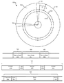
図1を見ると、破線として示された2つの例示的なトラック150、155を有するストレージ媒体100が示されている。トラックはウェッジ160、165内に書き込まれたサーボデータによって分離されている。これらのウェッジは、ストレージ媒体100上の所望のロケーションの上方で読取り/書込みヘッド機構を制御及び同期するのに用いられるサーボデータ161、166を含む。特に、このサーボデータは一般に、プリアンブルパターン、それに続くサーボアドレスマーク(SAM)を含む。サーボアドレスマークにはグレイコード(Gray code)が続き、グレイコードにはバースト情報が続く。2つのトラック及び2つのウェッジが示されているが、通常それぞれ数百個が所与のストレージ媒体上に含まれることに留意すべきである。また、サーボデータセットはバースト情報の2つ以上のフィールドを有することができることに留意すべきである。またさらに、バースト情報の後に現れる場合がある、例えば反復可能な振れ情報(run-out information)等の異なる情報をサーボフィールドに含めることができることに留意すべきである。ウェッジ160と165との間にユーザーデータ領域180が配置される。ユーザーデータ領域180の各トラック181はそれぞれの未使用ギャップ領域125、129によってそれぞれ隔てられた1つ又は複数のセクター123、127、131を含む。ユーザーデータのセクターのそれぞれは、プリアンブル190、同期191、ユーザーデータエリア193、及びセクター終了パッド195を含む。
Turning to FIG. 1, a
本発明の様々な実施形態は、ユーザーデータ領域180内の周期的情報を利用してフライハイト計算を実行する。そのようなデータを用いてフライハイト計算を実行することによって、複数のフライハイト有用データ領域が与えられる。本明細書において用いられるとき、「フライハイト有用データ領域」というフレーズは、フライハイトを計算するのに用いることができるデータを含む領域を意味するように、その最も広い意味で用いられる。いくつかの場合、フライハイトを計算するのに用いることができるデータは周期的データである。単なるいくつかの例として、フライハイト有用データ領域は、限定ではないが、規定の基準に適合するプリアンブル190、同期191、セクター終了パッド195、及びデータのランダムエリア193を含むことができる。いくつかの場合、フライハイト計算への従来の手法と比較して、上述したデータ領域を用いることによって比較的大きなデータ量が得られ、それによって所与の期間にわたる雑音低減平均化(noise reducing averaging)が増大し、それに応じてフライハイト計算の正確度の増大が得られる。代替的に又は付加的に、本手法は、ユーザーデータ領域からのデータが読み取られるときに、ストレージ媒体からのユーザーデータを用いてオンラインフライハイト計算を実行することを可能にすることができる。そのようなオンラインフライハイト計算は、ストレージ媒体に関連して実行される定期的な読取り動作及び書込み動作を必ずしも中断することを必要としない。本明細書において提供される開示に基づいて、当業者であれば、本発明の様々な実施形態による回路、システム、及び方法の実施態様によって達成することができる種々の他の利点を認識するであろう。本発明のいくつかの実施形態では、計算されたフライハイトを用いて、介在するサーボウェッジの処理中に読取り/書込みヘッド機構のロケーションを更新する。様々な場合に、特定の領域間の知覚又は識別された信頼性の差に依拠して異なるフライハイト有用データ領域に基づいて計算されたフライハイト情報に異なる重みが適用される。
Various embodiments of the present invention utilize the periodic information in the
図2を見ると、本発明の様々な実施形態によるユーザーデータに基づくフライハイト計算回路200が示されている。ユーザーデータに基づくフライハイト計算回路200は、中でも、サーボウェッジ間に延在するトラックに沿って格納されたユーザーデータを含むストレージ媒体212を備える。読取り/書込みヘッド機構210がストレージ媒体212に対して配置され、中でも、ストレージ媒体212上に格納された情報を感知し、感知された情報に対応する読取りデータ信号203を提供するように動作可能である。ストレージ媒体212は複数の形でフォーマット設定することができる。1つの例として、ストレージ媒体212は図1に関連して上記で検討したのと同様にフォーマット設定することができる。本明細書において提供される開示に基づいて、当業者であれば、本発明の様々な実施形態に関連して用いることができる種々のフォーマット、ストレージ媒体、及び/又は読取り/書込みヘッド機構を認識するであろう。
Turning to FIG. 2, a fly
読取りデータ信号203はアナログフロントエンド回路220に与えられる。アナログフロントエンド回路220は、当該技術分野において既知の任意のアナログフロントエンド回路とすることができる。図示されるように、アナログフロントエンド回路220は、前置増幅器回路223、アナログフィルター回路226、及びアナログ/デジタル変換器回路229を備える。読取り/書込みヘッド機構210からの読取りデータ信号203は前置増幅器回路223によって受信され、前置増幅器回路223は信号を増幅して増幅結果をアナログフィルター回路226に与える。アナログフィルター回路226は受信信号をフィルタリングし、対応するフィルタリングされた信号をアナログ/デジタル変換器回路229に与える。アナログ/デジタル変換器回路229は受信データに対応する一連のデジタルサンプル232を提供する。本明細書において提供される開示に基づいて、当業者であれば、本発明の様々な実施形態に関連して用いることができるアナログ/デジタル変換器回路229、アナログフィルター回路226、及び前置増幅器回路223の種々の実施態様を認識するであろう。
Read data signal 203 is provided to analog
デジタルサンプル232はデータ検出器回路235に与えられ、データ検出器回路235はデータ検出アルゴリズムを一連のデジタルサンプル223に適用して検出された出力238を得る。そして、検出された出力238は、更なる処理のために他の下流側のデータ処理回路(図示せず)に与えることができる。データ検出器回路235は、当該技術分野において既知の、データ検出プロセスを適用することが可能な任意の回路とすることができる。本発明の1つの特定の実施形態では、データ検出器回路235はビタビアルゴリズムデータ検出器回路である。本発明の他の実施形態では、データ検出器回路235は最大事後データ検出器回路である。本明細書において提供される開示に基づいて、当業者であれば、本発明の様々な実施形態に関連して用いることができる種々のデータ検出器回路を認識するであろう。
The
加えて、デジタルサンプル232はサンプルメモリ250に与えられ、該サンプルメモリ250において、デジタルサンプル232はフライハイトを計算することに関連して場合によって後に用いるために保持される。サンプルメモリ250は、ユーザーデータ信号204がアサートされるときに示されるようなユーザーデータ領域からデータをロードされる。ユーザーデータ信号204はユーザー/サーボデータ領域識別回路(図示せず)によってアサートすることができる。検出された出力238は、同期マークパターン検出器回路256、プリアンブル検出器回路259、セクター終了パターン検出器回路262、及びユーザーデータパターン検出器回路265に与えられる。同期マークパターン検出器回路256は、規定の同期マークパターンについて、検出された出力238を連続してクエリするように動作可能である。規定の同期マークパターンは、該パターンを「フライハイトに有用」にする或るレベルの周期性を含むように選択される。規定の同期マークパターンが識別されると、同期マークパターン検出器回路256は同期マーク発見出力257をアサートし、該同期マーク発見出力257はフライハイト計算回路270へのイネーブル入力として動作する。プリアンブル検出器回路259は、規定のプリアンブルパターンについて、検出された出力238を連続的にクエリするように動作可能である。規定のプリアンブルパターンは、該パターンを「フライハイトに有用」にする或るレベルの周期性を含むように選択される。規定のプリアンブルパターンが識別されると、プリアンブル検出器回路259はプリアンブル発見出力260をアサートし、該プリアンブル発見出力260はフライハイト計算回路273へのイネーブル入力として動作する。セクター終了パターン検出器回路262は、規定のセクター終了パターンについて、検出された出力238を連続的にクエリするように動作可能である。規定のセクター終了パターンは、該セクター終了パターンを「フライハイトに有用」にする或るレベルの周期性を含むように選択される。セクター終了パターンが識別されると、セクター終了パターン検出器回路262はセクター終了発見出力263をアサートし、該セクター終了発見出力263はフライハイト計算回路276へのイネーブル入力として動作する。ユーザーデータパターン検出器回路265は、ユーザーデータにランダムに現れる場合がある1つ又は複数の規定の周期的パターンについて、検出された出力238を連続的にクエリするように動作可能である。規定の周期的パターンは、プログラムされたユーザーデータパターンメモリ268にプログラムすることができ、パターン入力269としてユーザーデータパターン検出器回路265に提供される。規定の周期的パターンは、該パターンを「フライハイトに有用」にする或るレベルの周期性をそれぞれ含むように選択される。規定の周期的パターンのうちの1つが識別されると、ユーザーデータパターン検出器回路265は周期パターン発見出力266をアサートし、該周期パターン発見出力266はフライハイト計算回路279へのイネーブル入力として動作する。
In addition, the
フライハイト計算回路270、フライハイト計算回路273、フライハイト計算回路276、及びフライハイト計算回路279によって種々の異なるフライハイト計算を適用し、パターン入力253に基づいてそれぞれのフライハイト値を計算することができる。本発明の1つの特定の実施形態では、フライハイト計算回路270、フライハイト計算回路273、フライハイト計算回路276、及びフライハイト計算回路279のそれぞれが周期的データ入力及びウォレススペーシング損失理論に依存してフライハイト計算アルゴリズムを実施する。ウォレススペーシング損失理論は、任意の所与の周波数におけるリードバック信号強度が、V(k,d)∝exp(−d,k)に従って、フライハイトの増大とともに指数関数的に減衰することを示している。ここで「d」はフライハイトを表し、「k」は周波数を表す。これに従って、基準フライハイトd1からのフライハイトの変化を、以下の式に従って二次高調波測定(dual harmonics measurements)を用いて推定することができる。

{f1,f2}=高調波周波数、k=2π/λ
v=媒体の線形速度
ΔR=R2−R1=高調波比の変化
Δd=d2−d1=フライハイトの変化
{F 1 , f 2 } = harmonic frequency, k = 2π / λ
v = linear velocity of medium ΔR = R 2 −R 1 = change in harmonic ratio Δd = d 2 −d 1 = change in fly height
フライハイトに必要な高調波計算は、標準的なDFT(離散フーリエ変換)計算を用いて実行される。これらは以下によって与えられる。
本発明のいくつかの実施形態では、フライハイト計算回路270、フライハイト計算回路273、フライハイト計算回路276、及びフライハイト計算回路279のそれぞれを、それぞれ異なる形で実装することができることに留意すべきである。また、上述したフライハイト計算回路のそれぞれが異なる長さの入力パターン(すなわち、パターン入力253のそれぞれの部分)に対し動作することができることに留意すべきである。
It should be noted that in some embodiments of the present invention, each of fly
フライハイト計算回路270はフライハイト値271を平均回路282に与え、該平均回路282において、同期マークパターンに基づく受信フライハイト値の稼働平均(running average)が計算され、同期マークフライハイト平均283として与えられる。同様に、フライハイト計算回路273はフライハイト値274を平均回路285に与え、該平均回路285において、プリアンブルパターンに基づく受信フライハイト値の稼働平均が計算され、プリアンブルフライハイト平均286として与えられる。フライハイト計算回路276はフライハイト値277を平均回路288に与え、該平均回路288において、セクター終了パターンに基づく受信フライハイト値の稼働平均が計算され、セクター終了フライハイト平均289として与えられる。そしてフライハイト計算回路279はフライハイト値279を平均回路291に与え、該平均回路291において、ユーザーデータパターンに基づく受信フライハイト値の稼働平均が計算され、ユーザーデータフライハイト平均292として与えられる。
The fly
同期マークフライハイト平均283、プリアンブルフライハイト平均286、セクター終了フライハイト平均289、及びユーザーデータフライハイト平均292が正規化回路295に与えられ、該正規化回路295において、それらが結合され、単一の複合フライハイト値202にされる。例えば、4つ全てのフライハイト値が結合される場合、プリアンブルイネーブル信号296(プリアンブルフライハイト平均286に対応する)、ユーザーイネーブル信号297(ユーザーデータフライハイト値292に対応する)、セクター終了イネーブル298(セクター終了フライハイト平均289に対応する)、及び同期イネーブル299(同期マークフライハイト平均283に対応する)がアサートされる。プリアンブル信号の全てがアサートされている場合、正規化回路295は各入力を等しく重み付けし、以下の式に従って複合フライハイト出力202を得る。
複合フライハイト出力202=
(0.25)(同期マークフライハイト平均283)+
(0.25)(プリアンブルフライハイト平均286)+
(0.25)(セクター終了フライハイト平均289)+
(0.25)(ユーザーデータフライハイト平均292)。
代替的に、4つのイネーブルのうちの3つのみがアサートされている場合、正規化回路295は対応する3つの平均出力を結合して複合フライハイト出力202にし、アサートされていないイネーブルに対応する平均を除外する。例えば、ユーザーイネーブル信号297がアサートされておらず、他の3つのイネーブルがアサートされている場合、正規化回路295は以下の式に従って複合フライハイト出力202を与える。
複合フライハイト出力202=
(0.33)(同期マークフライハイト平均283)+
(0.33)(プリアンブルフライハイト平均286)+
(0.33)(セクター終了フライハイト平均289)。
代替的に、4つのイネーブルのうちの2つのみがアサートされている場合、正規化回路295はイネーブルされる2つの平均出力を結合して複合フライハイト出力202にし、アサートされていないイネーブルに対応する平均を除外する。例えば、ユーザーイネーブル信号297とプリアンブルイネーブル信号296がアサートされておらず、他の2つのイネーブルがアサートされている場合、正規化回路295は以下の式に従って複合フライハイト出力202を与える。
複合フライハイト出力202=
(0.50)(同期マークフライハイト平均283)+
(0.50)(セクター終了フライハイト平均289)。
代替的に、4つのイネーブルのうちの1つのみがアサートされている場合、正規化回路295はアサートされたイネーブルに対応する平均出力を複合フライハイト出力202として与え、アサートされていない3つのイネーブルに対応する平均を除外する。
The synchronization mark fly
Composite
(0.25) (synchronous mark fly height average 283) +
(0.25) (preamble fly height average 286) +
(0.25) (Sector end fly height average 289) +
(0.25) (user data fly height average 292).
Alternatively, if only three of the four enables are asserted, the
Composite
(0.33) (synchronous mark fly height average 283) +
(0.33) (preamble fly height average 286) +
(0.33) (Sector end fly height average 289).
Alternatively, if only two of the four enables are asserted,
Composite
(0.50) (synchronous mark fly height average 283) +
(0.50) (Sector end fly height average 289).
Alternatively, if only one of the four enables is asserted, the
結果としての複合フライハイト出力202がフライハイト調整回路201に与えられ、該フライハイト調整回路201は、複合フライハイト出力202の大きさ及び符号に従って読取り/書込みヘッド機構217と対応するストレージ媒体218との間の距離216(フライハイト)を調整するように動作可能である。フライハイト調整回路201は、フライハイトを調整することが可能な当該技術分野において既知の任意の回路とすることができる。
The resulting composite
図3を見ると、本発明の他の実施形態による別のユーザーデータに基づくフライハイト計算回路300が示されている。ユーザーデータに基づくフライハイト計算回路300は、中でも、サーボウェッジ間に延在するトラックに沿って格納されたユーザーデータを含むストレージ媒体312を備える。読取り/書込みヘッド機構310がストレージ媒体312に対して配置され、中でも、ストレージ媒体312上に格納された情報を感知し、感知された情報に対応する読取りデータ信号303を提供するように動作可能である。ストレージ媒体312は複数の形でフォーマット設定することができる。1つの例として、ストレージ媒体312は図1に関連して上記で検討したのと同様にフォーマット設定することができる。本明細書において提供される開示に基づいて、当業者であれば、本発明の様々な実施形態に関連して用いることができる種々のフォーマット、ストレージ媒体、及び/又は読取り/書込みヘッド機構を認識するであろう。
Turning to FIG. 3, a fly
読取りデータ信号303はアナログフロントエンド回路320に与えられる。アナログフロントエンド回路320は、当該技術分野において既知の任意のアナログフロントエンド回路とすることができる。図示されるように、アナログフロントエンド回路320は、前置増幅器回路323、アナログフィルター回路326、及びアナログ/デジタル変換器回路329を備える。読取り/書込みヘッド機構310からの読取りデータ信号303は前置増幅器回路323によって受信され、前置増幅器回路323は信号を増幅して増幅結果をアナログフィルター回路326に与える。アナログフィルター回路326は受信信号をフィルタリングし、対応するフィルタリングされた信号をアナログ/デジタル変換器回路329に与える。アナログ/デジタル変換器回路329は受信データに対応する一連のデジタルサンプル332を提供する。本明細書において提供される開示に基づいて、当業者であれば、本発明の様々な実施形態に関連して用いることができるアナログ/デジタル変換器回路329、アナログフィルター回路326、及び前置増幅器回路323の種々の実施態様を認識するであろう。
Read data signal 303 is provided to analog
デジタルサンプル332はデータ検出器回路335に与えられ、データ検出器回路335はデータ検出アルゴリズムを一連のデジタルサンプル323に適用して検出された出力338を得る。そして、検出された出力338は、更なる処理のために他のダウンストリームデータ処理回路(図示せず)に与えることができる。データ検出器回路335は、当該技術分野において既知の、データ検出プロセスを適用することが可能な任意の回路とすることができる。本発明の1つの特定の実施形態では、データ検出器回路335はビタビアルゴリズムデータ検出器回路である。本発明の他の実施形態では、データ検出器回路335は最大事後データ検出器回路である。本明細書において提供される開示に基づいて、当業者であれば、本発明の様々な実施形態に関連して用いることができる種々のデータ検出器回路を認識するであろう。
The
加えて、デジタルサンプル332はサンプルメモリ350に与えられ、該サンプルメモリ350において、デジタルサンプル332はフライハイトを計算することに関連して場合によって後に用いるために保持される。サンプルメモリ350は、ユーザーデータ信号204がアサートされるときに示されるようなユーザーデータ領域からのデータをロードしている。ユーザーデータ信号304はユーザー/サーボデータ領域識別回路(図示せず)によってアサートすることができる。検出された出力338は、同期マークパターン検出器回路356、プリアンブル検出器回路359、セクター終了パターン検出器回路362、及びユーザーデータパターン検出器回路365に与えられる。同期マークパターン検出器回路356は、規定の同期マークパターンについて、検出された出力338を連続してクエリするように動作可能である。規定の同期マークパターンは、該パターンを「フライハイトに有用」にする或るレベルの周期性を含むように選択される。規定の同期マークパターンが識別されると、同期マークパターン検出器回路356は同期マーク発見出力357をアサートし、該同期マーク発見出力357はフライハイト計算回路370へのイネーブル入力として動作する。プリアンブル検出器回路359は、規定のプリアンブルパターンについて、検出された出力338を連続的にクエリするように動作可能である。規定のプリアンブルパターンは、該パターンを「フライハイトに有用」にする或るレベルの周期性を含むように選択される。規定のプリアンブルパターンが識別されると、プリアンブル検出器回路359はプリアンブル発見出力360をアサートし、該プリアンブル発見出力360はフライハイト計算回路373へのイネーブル入力として動作する。セクター終了パターン検出器回路362は、所定のセクター終了パターンについて、検出された出力338を連続的にクエリするように動作可能である。規定のセクター終了パターンは、該セクター終了パターンを「フライハイトに有用」にする或るレベルの周期性を含むように選択される。セクター終了パターンが識別されると、セクター終了パターン検出器回路362はセクター終了発見出力363をアサートし、該セクター終了発見出力363はフライハイト計算回路376へのイネーブル入力として動作する。ユーザーデータパターン検出器回路365は、ユーザーデータにランダムに現れる場合がある1つ又は複数の所定の周期的パターンについて、検出された出力338を連続的にクエリするように動作可能である。規定の周期的パターンは、プログラムされたユーザーデータパターンメモリ268にプログラムすることができ、パターン入力369としてユーザーデータパターン検出器回路365に提供される。規定の周期的パターンは、該パターンを「フライハイトに有用」にする或るレベルの周期性をそれぞれ含むように選択される。規定の周期的パターンのうちの1つが識別されると、ユーザーデータパターン検出器回路365は周期パターン発見出力366をアサートし、該周期パターン発見出力366はフライハイト計算回路379のへのイネーブル入力として動作する。
In addition, the
フライハイト計算回路370、フライハイト計算回路373、フライハイト計算回路376、及びフライハイト計算回路379によって種々の異なるフライハイト計算を適用し、パターン入力353に基づいてそれぞれのフライハイト値を計算することができる。本発明の1つの特定の実施形態では、フライハイト計算回路370、フライハイト計算回路373、フライハイト計算回路376、及びフライハイト計算回路379のそれぞれが周期的データ入力及びウォレススペーシング損失理論に依存してフライハイト計算アルゴリズムを実施する。ウォレススペーシング損失理論は、任意の所与の周波数におけるリードバック信号強度が、V(k,d)∝exp(−d,k)に従って、フライハイトの増大とともに指数関数的に減衰することを示している。ここで「d」はフライハイトを表し、「k」は周波数を表す。これに従って、基準フライハイトd1からのフライハイトの変化を、以下の式に従って二次高調波測定を用いて推定することができる。
{f1,f2}=高調波周波数、k=2π/λ
v=媒体の線形速度
ΔR=R2−R1=高調波比の変化
Δd=d2−d1=フライハイトの変化
{F 1 , f 2 } = harmonic frequency, k = 2π / λ
v = linear velocity of medium ΔR = R 2 −R 1 = change in harmonic ratio Δd = d 2 −d 1 = change in fly height
フライハイトに必要な高調波計算は、標準的なDFT(離散フーリエ変換)計算を用いて実行される。これらは以下によって与えられる。
本発明のいくつかの実施形態では、フライハイト計算回路370、フライハイト計算回路373、フライハイト計算回路376、及びフライハイト計算回路379のそれぞれを、それぞれ異なる形で実装することができることに留意すべきである。また、上述したフライハイト計算回路のそれぞれが異なる長さの入力パターン(すなわち、パターン入力353のそれぞれの部分)に対し動作することができることに留意すべきである。
It should be noted that in some embodiments of the invention, each of fly
フライハイト計算回路371はフライハイト値371を平均回路382に与え、該平均回路382において、同期マークパターンに基づく受信フライハイト値の稼働平均が計算され、同期マークフライハイト平均383として与えられる。同様に、フライハイト計算回路373はフライハイト値374を平均回路385に与え、該平均回路385において、プリアンブルパターンに基づく受信フライハイト値の稼働平均が計算され、プリアンブルフライハイト平均386として与えられる。フライハイト計算回路376はフライハイト値377を平均回路388に与え、該平均回路388において、セクター終了パターンに基づく受信フライハイト値の稼働平均が計算され、セクター終了フライハイト平均389として与えられる。そしてフライハイト計算回路379はフライハイト値379を平均回路391に与え、該平均回路391において、ユーザーデータパターンに基づく受信フライハイト値の稼働平均が計算され、ユーザーデータフライハイト平均392として与えられる。
The fly
同期マークフライハイト平均383、プリアンブルフライハイト平均386、セクター終了フライハイト平均389、及びユーザーデータフライハイト平均392は正規化回路395に与えられ、該正規化回路395は、それらを以下の式に従って、入力重み(プリアンブルフライハイト平均386に対応するプリアンブルWT396、ユーザーデータフライハイト平均392に対応するユーザーWT397、セクター終了フライハイト平均389に対応するセクター終了WT398、及び同期マークフライハイト平均383に対応するWT399)を用いて結合し、単一の複合フライハイト値302にする。
複合フライハイト出力302=
(同期WT399)(同期マークフライハイト平均383)+
(プリアンブルWT396)(プリアンブルフライハイト平均386)+
(セクター終了WT398)(セクター終了フライハイト平均389)+
(ユーザーWT397)(ユーザーデータフライハイト平均392)。
いくつかの実施形態では、プリアンブルWT396、ユーザーWT397、セクター終了WT398、及び同期WT399の和は1である。
The synchronization mark fly
Composite
(Synchronous WT 399) (Synchronous mark fly height average 383) +
(Preamble WT396) (preamble fly height average 386) +
(Sector end WT398) (Sector end fly height average 389) +
(User WT 397) (User data fly height average 392).
In some embodiments, the sum of
結果としての複合フライハイト出力302はフライハイト調整回路301に与えられ、該フライハイト調整回路301は複合フライハイト出力202の大きさ及び符号に従って読取り/書込みヘッド機構317と対応するストレージ媒体318との間の距離316(フライハイト)を調整するように動作可能である。フライハイト調整回路301は、フライハイトを調整することが可能な当該技術分野において既知の任意の回路とすることができる。
The resulting composite
図4を見ると、流れ図400が、本発明の1つ又は複数の実施形態による、ユーザーデータに基づいてフライハイトを計算する方法を示している。流れ図400に従って、アナログ入力が連続して受信される(ブロック405)。いくつかの場合、このアナログ信号はストレージ媒体から受信されたアナログフロントエンド回路処理情報から受信される。アナログ入力はアナログ/デジタル変換器回路によって一連のデジタルサンプルに変換される(ブロック410)。一連のデジタルサンプルへの変換は、当該技術分野において既知の任意のアナログ/デジタル変換方法を用いて行うことができる。一連のデジタルサンプルにデータ処理が適用され、データ出力が得られる(ブロック415)。いくつかの場合、このデータ処理は、例えば最大事後データ検出プロセス又はビタビアルゴリズムデータ検出プロセス等の当該技術分野において既知のデータ検出プロセスとすることができる。本明細書において提供される開示に基づいて、当業者であれば本発明の様々な実施形態に関連して用いることができる種々のデータ検出プロセスを認識するであろう。
Turning to FIG. 4, a
ユーザーデータ領域(すなわち2つのサーボデータウェッジ間の領域)が処理されているか否かが判断される(ブロック418)。ユーザーデータ領域が処理されている場合、ユーザーデータの1つ又は複数のセクターに関連付けられたプリアンブルが見つかっているか否かが判断される(ブロック420)。プリアンブルが見つかっている場合(ブロック420)、識別されたプリアンブルに対応する受信したデジタルサンプルが識別される(ブロック425)。これらの識別されたデジタルサンプルを用いて、プリアンブルに基づいてフライハイト値を計算する(ブロック430)。フライハイトは当該技術分野において既知の任意のフライハイト計算アルゴリズムを用いて計算することができる。プリアンブルに基づいて計算されたフライハイトは他の同様のフライハイト値の稼働平均に組み込まれ、平均化されたプリアンブルフライハイトが得られる(ブロック435)。 It is determined whether a user data area (ie, an area between two servo data wedges) has been processed (block 418). If the user data area is being processed, it is determined whether a preamble associated with one or more sectors of user data has been found (block 420). If a preamble is found (block 420), a received digital sample corresponding to the identified preamble is identified (block 425). Using these identified digital samples, a fly height value is calculated based on the preamble (block 430). Fly height can be calculated using any fly height calculation algorithm known in the art. The fly height calculated based on the preamble is incorporated into a running average of other similar fly height values to obtain an averaged preamble fly height (block 435).
代替的に、プリアンブルが見つかっていない場合(ブロック420)、ユーザーデータの1つ又は複数のセクターに関連付けられたユーザー同期マークが見つかっているか否かが判断される(ブロック440)。ユーザー同期マークが見つかっている場合(ブロック440)、識別されたユーザー同期マークに対応する受信したデジタルサンプルが識別される(ブロック445)。これらの識別されたデジタルサンプルを用いて、ユーザー同期マークに基づいてフライハイト値を計算する(ブロック450)。フライハイトは当該技術分野において既知の任意のフライハイト計算アルゴリズムを用いて計算することができる。ユーザー同期マークに基づいて計算されたフライハイトは他の同様のフライハイト値の稼働平均に組み込まれて、平均化された同期マークフライハイトを得る(ブロック455)。 Alternatively, if the preamble is not found (block 420), it is determined whether a user sync mark associated with one or more sectors of user data has been found (block 440). If a user sync mark is found (block 440), a received digital sample corresponding to the identified user sync mark is identified (block 445). Using these identified digital samples, a fly height value is calculated based on the user synchronization mark (block 450). Fly height can be calculated using any fly height calculation algorithm known in the art. The fly height calculated based on the user sync mark is incorporated into a running average of other similar fly height values to obtain an averaged sync mark fly height (block 455).
代替的に、プリアンブルが見つかっていない場合(ブロック440)、ユーザーデータの1つ又は複数のセクターに関連付けられたセクター終了マークが見つかっているか否かが判断される(ブロック460)。セクター終了マークが見つかっている場合(ブロック460)、識別されたセクター終了マークに対応する受信したデジタルサンプルが識別される(ブロック465)。これらの識別されたデジタルサンプルを用いて、セクター終了マークに基づいてフライハイト値を計算する(ブロック470)。フライハイトは当該技術分野において既知の任意のフライハイト計算アルゴリズムを用いて計算することができる。セクター終了マークに基づいて計算されたフライハイトは、他の同様のフライハイト値の稼働平均に組み込まれ、平均化されたセクター終了フライハイトが得られる(ブロック475)。 Alternatively, if no preamble is found (block 440), it is determined whether a sector end mark associated with one or more sectors of user data has been found (block 460). If an end of sector mark is found (block 460), the received digital sample corresponding to the identified end of sector mark is identified (block 465). Using these identified digital samples, a fly height value is calculated based on the end of sector mark (block 470). Fly height can be calculated using any fly height calculation algorithm known in the art. The fly height calculated based on the end of sector mark is incorporated into a running average of other similar fly height values to obtain an averaged sector end fly height (block 475).
代替的に、セクター終了マークが見つかっていない場合(ブロック460)、ユーザーデータ内の所定のパターンが見つかっているか否かが判断される(ブロック480)。そのような所定のパターンが見つかっている場合(ブロック480)、識別された所定のパターンに対応する受信したデジタルサンプルが識別される(ブロック485)。これらの識別されたデジタルサンプルを用いて、所定のパターンに基づいてフライハイト値を計算する(ブロック490)。フライハイトは、当該技術分野において既知の任意のフライハイト計算アルゴリズムを用いて計算することができる。所定のパターンに基づいて計算されたフライハイトは他の同様のフライハイト値の稼働平均に組み込まれて、平均化されたユーザーデータパターンフライハイトが得られる(ブロック495)。 Alternatively, if a sector end mark is not found (block 460), it is determined whether a predetermined pattern in the user data is found (block 480). If such a predetermined pattern is found (block 480), the received digital samples corresponding to the identified predetermined pattern are identified (block 485). Using these identified digital samples, a fly height value is calculated based on a predetermined pattern (block 490). Fly height can be calculated using any fly height calculation algorithm known in the art. The fly height calculated based on the predetermined pattern is incorporated into a running average of other similar fly height values to obtain an averaged user data pattern fly height (block 495).
平均化されたプリアンブルフライハイト、平均化されたユーザー同期フライハイト、平均化されたセクター終了フライハイト、及び平均化されたユーザーデータフライハイトを用いて重み付けされた正規化を実行し、複合フライハイト値を得る(ブロック401)。いくつかの場合、複合値は以下の式に従って計算される。
複合フライハイト出力=
(同期マーク重み)(平均化された同期マーク)+
(プリアンブル重み)(平均化されたプリアンブルフライハイト)+
(セクター終了重み)(平均化されたセクター終了フライハイト)+
(ユーザーデータ重み)(平均化されたユーザーデータフライハイト).
いくつかの実施形態では、同期マーク重み、プリアンブル重み、ユーザーデータ重み、セクター終了重み、及びユーザーデータ重みはプログラム可能な重み係数であり、いくつかの場合、4つの重み係数の和は1である。次に複合フライハイト値を用いてフライハイトを変更する(ブロック402)。
Perform weighted normalization using averaged preamble fly height, averaged user sync fly height, averaged sector end fly height, and averaged user data fly height to obtain a composite fly height value (block 401). In some cases, the composite value is calculated according to the following formula:
Combined fly height output =
(Sync mark weight) (averaged sync mark) +
(Preamble weight) (averaged preamble fly height) +
(Sector end weight) (Averaged sector end fly height) +
(User data weight) (averaged user data fly height).
In some embodiments, the sync mark weight, preamble weight, user data weight, sector end weight, and user data weight are programmable weight factors, and in some cases the sum of the four weight factors is 1. . Next, the fly height is changed using the composite fly height value (block 402).
図5aを見ると、本発明の1つ又は複数の実施形態による、ユーザーデータに基づくフライハイト計算回路部を有する読取りチャネル回路510を備えるストレージデバイス500が示されている。ストレージデバイス500は、例えばハードディスクドライブとすることができる。また、読取りチャネル回路510は、例えばビタビアルゴリズムデータ検出器等のデータ検出器、及び/又は、例えば低密度パリティチェック復号器回路等のデータ復号器回路を備えることができる。ストレージデバイス500は、読取りチャネル回路510に加えて、ディスクプラッター578に対して配置された読取り/書込みヘッド機構576を備える。読取り/書込みヘッド機構576は、ディスクプラッター578上に格納された情報を感知し、対応する電気信号を読取りチャネル回路510に与えるように動作可能である。
Turning to FIG. 5a, a
ストレージデバイス500は、インターフェースコントローラー520、ハードディスクコントローラー566、モーターコントローラー及びフライハイトコントローラー568、並びにスピンドルモーター572も備える。インターフェースコントローラー520はディスクプラッター578への/からのデータのアドレス指定及びタイミングを制御する。ディスクプラッター378上のデータは、読取り/書込みヘッド機構576がディスクプラッター578上に適切に位置決めされているときに該機構によって検出することができる磁気信号の群からなる。1つの実施形態では、ディスクプラッター578は垂直記録方式に従って記録された磁気信号を含む。本発明の他の実施形態では、ディスクプラッター578は長手記録方式に従って記録された磁気信号を含む。モーターコントローラー及びフライハイトコントローラー568はディスクプラッター578のスピンレート及びディスクプラッター578に対する読取り/書込みヘッド機構576のロケーションを制御する。
The
図5bの断面図491に示すように、読取り/書込みヘッド機構576とディスクプラッター578の間の距離はフライハイト590である。フライハイト590は読取りチャネル回路510によって与えられる高調波値512に基づいてモーターコントローラー及びフライハイトコントローラー568によって制御される。
The distance between read /
通常の読み取り動作では、読取り/書込みヘッド機構576は、モーターコントローラー及びフライハイトコントローラー568によってディスクプラッター578上の所望のデータトラックの上方に正確に位置決めされる。モーターコントローラー及びフライハイトコントローラー568は、読取り/書込みヘッド機構576をディスクプラッター578に対して(横方向及び垂直方向に)位置決めし、かつハードディスクコントローラー566の指示の下で読取り/書込みヘッド機構576をディスクプラッター578上の適切なデータトラックに移動させることによってスピンドルモーター572を駆動する。スピンドルモーター572は定められたスピンレート(RPM)でディスクプラッター578をスピンする。読取り/書込みヘッド機構578が適切なデータトラックに近接して位置決めされると、スピンドルモーター572によってディスクプラッター578が回転するのに応じてディスクプラッター578上のデータを表す磁気信号が読取り/書込みヘッド機構576によって感知される。感知された磁気信号は、ディスクプラッター578上の磁気データを表す連続した微小アナログ信号として与えられる。この微小アナログ信号は、読取り/書込みヘッド機構576によって、読取りチャネル回路510に与えられる。そして、読取りチャネル回路510は受信したアナログ信号を復号及びデジタル化し、ディスクプラッター578に元々書き込まれた情報を再生する。このデータは、読取りデータ503として受信回路に与えられる。書込み動作は、先行する読取り動作と実質的に反対であり、書込みデータ501が読取りチャネル回路510に与えられる。次にこのデータは符号化され、ディスクプラッター578に書き込まれる。
In a normal read operation, the read /
時に、ディスクプラッター578から取り出された信号を処理してフライハイトを求めることができる。本発明のいくつかの実施形態では、フライハイトを求めることは、図4に関連して上記で検討した方法と一致するように行うことができる。様々な場合に、上記で図2又は図3に関連して検討した回路と一致する回路を用いてユーザーデータに基づくフライハイト計算を実行することができる。様々な場合に、フライハイトは、ストレージデバイス500の動作状態の変化が検出されたときに再評価される。そのような動作の変化は、限定ではないが、動作電圧レベルの変化、動作温度の変化、高度の変化、ビット誤り率の変化を含むことができる。本明細書において提供される開示に基づいて、当業者であれば、ストレージデバイス500において監視することができる種々の動作状態、及びそのような状態の変化を利用してフライハイトの再評価をトリガーすることができる方法を認識するであろう。
Sometimes the fly height can be determined by processing the signal retrieved from the
ストレージシステム500は、例えばRAID(低価格ディスク冗長アレイ又は独立ディスク冗長アレイ)ベースのストレージシステム等のより大きなストレージシステムに統合することができることに留意すべきである。また、ストレージシステム500の様々な機能又はブロックをソフトウェア又はファームウェアのいずれかに実装することができる一方、他の機能又はブロックはハードウェアに実装されることにも留意すべきである。
It should be noted that the
上記のアプリケーションにおいて検討された様々なブロックは、他の機能とともに集積回路において実施することができることに留意すべきである。そのような集積回路は、所与のブロック、システム、若しくは回路の機能のすべて、又はブロック、システム、若しくは回路の部分集合のみを含むことができる。また、ブロック、システム、又は回路の要素を複数の集積回路にわたって実装することができる。そのような集積回路は、限定ではないが、モノリシック集積回路、フリップチップ集積回路、マルチチップモジュール集積回路、及び/又は混合信号集積回路を含む、当該技術分野において既知の任意のタイプの集積回路とすることができる。本明細書において検討されたブロック、システム、又は回路の様々な機能を、ソフトウェア又はファームウェアのいずれでも実施することができることにも留意すべきである。いくつかのそのような場合、システム、ブロック、又は回路全体を、そのソフトウェア等価物又はファームウェア等価物を用いて実施することができる。他の場合、所与のシステム、ブロック、又は回路の一部分をソフトウェア又はファームウェアにおいて実装することもできる一方、他の部分はハードウェアにおいて実装される。 It should be noted that the various blocks discussed in the above application can be implemented in an integrated circuit along with other functions. Such integrated circuits can include all of the functions of a given block, system, or circuit, or only a subset of the block, system, or circuit. Also, a block, system, or circuit element may be implemented across multiple integrated circuits. Such integrated circuits include any type of integrated circuit known in the art including, but not limited to, monolithic integrated circuits, flip chip integrated circuits, multichip module integrated circuits, and / or mixed signal integrated circuits. can do. It should also be noted that the various functions of the blocks, systems, or circuits discussed herein can be implemented in either software or firmware. In some such cases, the system, block, or entire circuit may be implemented using its software equivalent or firmware equivalent. In other cases, portions of a given system, block, or circuit may be implemented in software or firmware, while other portions are implemented in hardware.
結論として、本発明は高調波を測定する新規なシステム、デバイス、方法、及び構成を提供する。本発明の1つ又は複数の実施形態の詳細な説明が上記で与えられたが、本発明の趣旨を変えることなく、様々な代替形態、変更形態、及び等価物が当業者には明らかとなろう。したがって、上記の説明は本発明の範囲を限定するものとして解釈されるべきではなく、本発明の範囲は添付の特許請求の範囲によって規定される。 In conclusion, the present invention provides a novel system, device, method and configuration for measuring harmonics. While a detailed description of one or more embodiments of the invention has been given above, various alternatives, modifications, and equivalents will become apparent to those skilled in the art without departing from the spirit of the invention. Let's go. Therefore, the above description should not be taken as limiting the scope of the invention, which is defined by the appended claims.
Claims (20)
受信したデータセット内の第1のパターンを識別するように動作可能な第1パターン検出器回路であって、該受信したデータセットは第1のサーボデータ領域と第2のサーボデータ領域との間に配置されたユーザーデータに対応する、第1パターン検出器回路と、
該第1のパターンに対応するデータ値を用いて第1のフライハイトを計算し、第1パターンフライハイト出力を得るように動作可能な第1パターンフライハイト計算回路と、
該第1パターンフライハイト出力を該第1のフライハイト出力の他のインスタンスで平均化し、第1の平均化された出力を得るように動作可能な第1の平均化回路と、
該受信したデータセット内の第2のパターンを識別するように動作可能な第2パターン検出器回路と、
該第2のパターンに対応するデータ値を用いて第2のフライハイトを計算して第2パターンフライハイト出力を得るように動作可能な第2パターンフライハイト計算回路と、
該第2パターンフライハイト出力を該第2パターンフライハイト出力の他のインスタンスで平均化し、第2の平均化された出力を得るように動作可能な第2の平均化回路と、
少なくとも該第1の平均化された出力及び該第2の平均化された出力を結合して複合フライハイト値を得るように動作可能な結合回路と、
を備える、フライハイト値を計算する回路。 A circuit for calculating a fly height value,
A first pattern detector circuit operable to identify a first pattern in a received data set, wherein the received data set is between a first servo data region and a second servo data region. A first pattern detector circuit corresponding to user data arranged in
A first pattern fly height calculation circuit operable to calculate a first fly height using a data value corresponding to the first pattern and obtain a first pattern fly height output;
A first averaging circuit operable to average the first pattern fly height output with other instances of the first fly height output to obtain a first averaged output;
A second pattern detector circuit operable to identify a second pattern in the received data set;
A second pattern fly height calculation circuit operable to calculate a second fly height using a data value corresponding to the second pattern to obtain a second pattern fly height output;
A second averaging circuit operable to average the second pattern fly height output with other instances of the second pattern fly height output to obtain a second averaged output;
A coupling circuit operable to combine at least the first averaged output and the second averaged output to obtain a composite fly height value;
A circuit for calculating a fly height value.
該第1の平均化された出力に第1の重み係数を乗算して第1の加重値を得て、
該第2の平均化された出力に第2の重み係数を乗算して第2の加重値を得て、
少なくとも該第1の加重値及び該第2の加重値を合算して該複合フライハイト値を得るように動作可能である、請求項1に記載の回路。 The coupling circuit is
Multiplying the first averaged output by a first weighting factor to obtain a first weighting value;
Multiplying the second averaged output by a second weighting factor to obtain a second weighting value;
The circuit of claim 1, wherein the circuit is operable to add at least the first weight value and the second weight value to obtain the composite fly height value.
該受信したデータセット内のプリアンブルパターンを識別するように動作可能なプリアンブルパターン検出器回路と、
該プリアンブルパターンに対応するデータ値を用いて第3のフライハイトを計算し、第3パターンフライハイト出力を得るように動作可能な第3パターンフライハイト計算回路と、
該第3パターンフライハイト出力を該第3のフライハイト出力の他のインスタンスで平均化して第3の平均化された出力を得るように動作可能な第3の平均化回路と、
を更に備え、該結合回路は、少なくとも該第1の平均化された出力、該第2の平均化された出力、及び該第3の平均化された出力を結合して該複合フライハイト値を得るように更に動作可能である、請求項9に記載の回路。 Circuit
A preamble pattern detector circuit operable to identify a preamble pattern in the received data set;
A third pattern fly height calculation circuit operable to calculate a third fly height using a data value corresponding to the preamble pattern and obtain a third pattern fly height output;
A third averaging circuit operable to average the third pattern fly height output with other instances of the third fly height output to obtain a third averaged output;
The combining circuit combines at least the first averaged output, the second averaged output, and the third averaged output to obtain the composite fly height value. The circuit of claim 9, further operable.
該所定のパターンに対応するデータ値を用いて第3のフライハイトを計算し、第3パターンフライハイト出力を得るように動作可能な第3パターンフライハイト計算回路と、
該第3パターンフライハイト出力を該第3のフライハイト出力の他のインスタンスで平均化して第3の平均化された出力を得るように動作可能な第3の平均化回路と、
を更に備え、該結合回路は、少なくとも該第1の平均化された出力、該第2の平均化された出力、及び該第3の平均化された出力を結合して該複合フライハイト値を得るように更に動作可能である、請求項9に記載の回路。 A predetermined pattern detector circuit in a user data region operable to identify a predetermined pattern in a received data set;
A third pattern fly height calculation circuit operable to calculate a third fly height using a data value corresponding to the predetermined pattern and obtain a third pattern fly height output;
A third averaging circuit operable to average the third pattern fly height output with other instances of the third fly height output to obtain a third averaged output;
The combining circuit combines at least the first averaged output, the second averaged output, and the third averaged output to obtain the composite fly height value. The circuit of claim 9, further operable.
データセットを受信することであって、該データセットはヘッド機構を介してストレージ媒体から取り出され、該データセットは第1のサーボデータ領域と第2のサーボデータ領域との間に配置されたユーザーデータに対応する、受信すること、
該受信したデータセット内の第1のパターンを識別すること、
該第1のパターンに対応するデータ値を用いて第1のフライハイトを計算することであって、第1パターンフライハイト出力を得る、計算すること、
該第1パターンフライハイト出力を該第1のフライハイト出力の他のインスタンスで平均化することであって、第1の平均化された出力を得る、平均化すること、
該受信したデータセット内の第2のパターンを識別すること、
該第2のパターンに対応するデータ値を用いて第2のフライハイトを計算することであって、第2パターンフライハイト出力を得る、計算すること、
該第2パターンフライハイト出力を該第2のフライハイト出力の他のインスタンスで平均化することであって、第2の平均化された出力を得る、平均化すること、
少なくとも該第1の平均化された出力及び該第2の平均化された出力を結合することであって、複合フライハイト値を得る、結合すること、並びに、
少なくとも部分的に該複合フライハイト値に基づいて該ヘッド機構と該ストレージ媒体との間の距離を変更すること、
を含む、フライハイト変更の方法。 A method for changing fly height,
Receiving a data set, wherein the data set is retrieved from a storage medium via a head mechanism, the data set being disposed between a first servo data area and a second servo data area; Corresponding to data, receiving,
Identifying a first pattern in the received data set;
Calculating a first fly height using data values corresponding to the first pattern, obtaining a first pattern fly height output;
Averaging the first pattern fly height output with other instances of the first fly height output to obtain a first averaged output;
Identifying a second pattern in the received data set;
Calculating a second fly height using data values corresponding to the second pattern to obtain a second pattern fly height output;
Averaging the second pattern fly height output with other instances of the second fly height output to obtain a second averaged output;
Combining at least the first averaged output and the second averaged output to obtain a composite fly height value; and
Changing the distance between the head mechanism and the storage medium based at least in part on the composite fly height value;
Including fly height change method.
該第1の平均化された出力に第1の重み係数を乗算することであって、第1の加重値を得る、乗算すること、
該第2の平均化された出力に該第2の重み係数を乗算することであって、第2の加重値を得る、乗算すること、並びに
少なくとも該第1の加重値及び該第2の加重値を合算することであって、該複合フライハイト値を得る、合算すること、
を含む、請求項13に記載の方法。 Combining at least the first averaged output and the second averaged output to obtain the composite fly height value,
Multiplying the first averaged output by a first weighting factor to obtain a first weighting value;
Multiplying the second averaged output by the second weighting factor to obtain a second weighting value, multiplying, and at least the first weighting value and the second weighting Summing the values, obtaining the composite fly height value, summing,
14. The method of claim 13, comprising:
第1のサーボデータ領域、第2のサーボデータ領域、及び該第1のサーボデータ領域と該第2のサーボデータ領域との間に配置されたユーザーデータ領域を備えるストレージ媒体と、
該ストレージ媒体に対して配置された読取り/書込みヘッド機構であって、該ユーザーデータ領域に対応する電気信号を与えるように動作可能な読取り/書込みヘッド機構と、
該電気信号から取り出したものを該ユーザーデータ領域に対応するデータセットに変換するように動作可能なアナログ/デジタル変換器回路と、
該データセット内の第1のパターンを識別するように動作可能な第1パターン検出器回路と、
該第1のパターンに対応するデータ値を用いて第1のフライハイトを計算し、第1パターンフライハイト出力を得るように動作可能な第1パターンフライハイト計算回路と、
該第1パターンフライハイト出力を該第1のフライハイト出力の他のインスタンスで平均化して第1の平均化された出力を得るように動作可能な第1の平均化回路と、
該受信したデータセット内の第2のパターンを識別するように動作可能な第2パターン検出器回路と、
該第2のパターンに対応するデータ値を用いて第2のフライハイトを計算し、第2パターンフライハイト出力を得るように動作可能な第2パターンフライハイト計算回路と、
該第2パターンフライハイト出力を該第2パターンフライハイト出力の他のインスタンスで平均化して第2の平均化された出力を得るように動作可能な第2の平均化回路と、
少なくとも該第1の平均化された出力及び該第2の平均化された出力を結合して複合フライハイト値を得るように動作可能な結合回路と、
少なくとも部分的に該複合フライハイト値に基づいて該読取り/書込みヘッド機構と該ストレージ媒体との間の距離を変更するように動作可能なフライハイト調整回路と、
を備える、ストレージデバイス。 A storage device,
A storage medium comprising a first servo data area, a second servo data area, and a user data area disposed between the first servo data area and the second servo data area;
A read / write head mechanism disposed relative to the storage medium, the read / write head mechanism operable to provide an electrical signal corresponding to the user data area;
An analog to digital converter circuit operable to convert the electrical signal derived into a data set corresponding to the user data region;
A first pattern detector circuit operable to identify a first pattern in the data set;
A first pattern fly height calculation circuit operable to calculate a first fly height using a data value corresponding to the first pattern and obtain a first pattern fly height output;
A first averaging circuit operable to average the first pattern fly height output with other instances of the first fly height output to obtain a first averaged output;
A second pattern detector circuit operable to identify a second pattern in the received data set;
A second pattern fly height calculation circuit operable to calculate a second fly height using a data value corresponding to the second pattern and obtain a second pattern fly height output;
A second averaging circuit operable to average the second pattern fly height output with other instances of the second pattern fly height output to obtain a second averaged output;
A coupling circuit operable to combine at least the first averaged output and the second averaged output to obtain a composite fly height value;
A fly height adjustment circuit operable to change a distance between the read / write head mechanism and the storage medium based at least in part on the composite fly height value;
A storage device.
Applications Claiming Priority (2)
| Application Number | Priority Date | Filing Date | Title |
|---|---|---|---|
| US13/185,562 US8526133B2 (en) | 2011-07-19 | 2011-07-19 | Systems and methods for user data based fly height calculation |
| US13/185,562 | 2011-07-19 |
Publications (2)
| Publication Number | Publication Date |
|---|---|
| JP2013025858A true JP2013025858A (en) | 2013-02-04 |
| JP2013025858A5 JP2013025858A5 (en) | 2015-02-26 |
Family
ID=46177326
Family Applications (1)
| Application Number | Title | Priority Date | Filing Date |
|---|---|---|---|
| JP2012010626A Ceased JP2013025858A (en) | 2011-07-19 | 2012-01-23 | System and method for flying height calculation based on user data |
Country Status (6)
| Country | Link |
|---|---|
| US (1) | US8526133B2 (en) |
| EP (1) | EP2549477A1 (en) |
| JP (1) | JP2013025858A (en) |
| KR (1) | KR20130010829A (en) |
| CN (1) | CN102890939A (en) |
| TW (1) | TWI540572B (en) |
Families Citing this family (8)
| Publication number | Priority date | Publication date | Assignee | Title |
|---|---|---|---|---|
| US8908306B1 (en) * | 2013-03-15 | 2014-12-09 | Western Digital Technologies, Inc. | Disk drive measuring channel transition response by averaging isolated transitions in a read signal |
| US9001451B1 (en) | 2013-08-12 | 2015-04-07 | Seagate Technology Llc | Clearance distance verification and control |
| JP6341271B2 (en) * | 2014-03-04 | 2018-06-13 | 株式会社大阪ソーダ | Battery electrode binder, and electrode and battery using the same |
| GB2536435B (en) * | 2015-03-16 | 2018-02-28 | Nexeon Ltd | Electroactive materials for metal-ion batteries |
| US9502063B1 (en) * | 2016-01-04 | 2016-11-22 | Seagate Technology Llc | Apparatus and method for measuring slider fly height relative to bit patterned media |
| CN109655311A (en) * | 2018-12-21 | 2019-04-19 | 武汉飞流智能技术有限公司 | A kind of water quality probe depthkeeping system and method suitable for unmanned plane |
| US11295774B1 (en) | 2021-06-11 | 2022-04-05 | Western Digital Technologies, Inc. | Data storage device calibrating fly height actuator for multiple heads during a revolution |
| US11721364B1 (en) | 2022-03-14 | 2023-08-08 | Seagate Technology Llc | Adaptive read clearance for improving reader reliability |
Citations (5)
| Publication number | Priority date | Publication date | Assignee | Title |
|---|---|---|---|---|
| JP2008192244A (en) * | 2007-02-05 | 2008-08-21 | Fujitsu Ltd | Device and method for measuring flying height, and storage device |
| JP2008204548A (en) * | 2007-02-20 | 2008-09-04 | Fujitsu Ltd | Vertical magnetic disk device |
| JP2011018396A (en) * | 2009-07-08 | 2011-01-27 | Hitachi Global Storage Technologies Netherlands Bv | Disk drive and clearance measuring method |
| JP2011507138A (en) * | 2007-12-14 | 2011-03-03 | エルエスアイ コーポレーション | System and method for flying height control using servo address mark data |
| JP2012009110A (en) * | 2010-06-24 | 2012-01-12 | Toshiba Corp | Disk storage device and head flying height measurement method |
Family Cites Families (30)
| Publication number | Priority date | Publication date | Assignee | Title |
|---|---|---|---|---|
| JPH0631989B2 (en) | 1985-11-14 | 1994-04-27 | ロ−ランド株式会社 | Waveform generator for electronic musical instruments |
| US4777544A (en) | 1986-08-15 | 1988-10-11 | International Business Machine Corporation | Method and apparatus for in-situ measurement of head/recording medium clearance |
| US5086475A (en) | 1988-11-19 | 1992-02-04 | Sony Corporation | Apparatus for generating, recording or reproducing sound source data |
| US5111727A (en) | 1990-01-05 | 1992-05-12 | E-Mu Systems, Inc. | Digital sampling instrument for digital audio data |
| US5377058A (en) | 1992-12-31 | 1994-12-27 | International Business Machines Corporation | Fly height servo control of read/write head suspension |
| US5814750A (en) | 1995-11-09 | 1998-09-29 | Chromatic Research, Inc. | Method for varying the pitch of a musical tone produced through playback of a stored waveform |
| US5909330A (en) | 1996-12-12 | 1999-06-01 | Maxtor Corporation | Method and apparatus for detecting head flying height in a disk drive |
| US6097559A (en) | 1998-06-26 | 2000-08-01 | International Business Machines Corporation | System and method for detecting head-to-disk contact in-situ a direct access storage device using a position error signal |
| US6519102B1 (en) | 2000-04-27 | 2003-02-11 | International Business Machines Corporation | Method and apparatus for implementing an in-situ digital harmonic computation facility for direct access storage device (DASD) |
| US6900381B2 (en) | 2001-05-16 | 2005-05-31 | Telefonaktiebolaget Lm Ericsson (Publ) | Method for removing aliasing in wave table based synthesizers |
| US7222289B2 (en) | 2002-09-30 | 2007-05-22 | Certance Llc | Channel processor using reduced complexity LDPC decoder |
| US7199961B1 (en) * | 2003-03-25 | 2007-04-03 | Marvell International Ltd. | Detecting fly height of a head over a storage medium |
| US6937424B2 (en) | 2003-05-12 | 2005-08-30 | Hitachi Global Storage Technologies Netherlands N.V. | Repeatable runout (RRO) compensation methods and apparatus for data storage devices |
| US7038875B2 (en) | 2003-07-31 | 2006-05-02 | Seagate Technology Llc | Dynamic measurement of head media spacing modulation |
| US7016131B2 (en) | 2003-08-29 | 2006-03-21 | Agency For Science, Technology And Research | Method and implementation of in-situ absolute head medium spacing measurement |
| US7158325B1 (en) | 2003-11-06 | 2007-01-02 | Maxtor Corporation | Disk drive head touchdown detection with improved discrimination |
| JP2006202391A (en) * | 2005-01-20 | 2006-08-03 | Hitachi Global Storage Technologies Netherlands Bv | Magnetic disk drive and method for measuring flying height |
| US7715135B1 (en) * | 2005-09-20 | 2010-05-11 | Marvell International Ltd. | Methods, circuits, apparatus, and systems for read channel synchronization and/or fly height measurement |
| JP2007242152A (en) * | 2006-03-09 | 2007-09-20 | Fujitsu Ltd | Magnetic recording medium, magnetic recorder, and servo demodulation circuit |
| JP2007242167A (en) * | 2006-03-09 | 2007-09-20 | Fujitsu Ltd | Floating height measuring instrument and method |
| JP4978625B2 (en) | 2006-05-12 | 2012-07-18 | 日本電気株式会社 | Error correction coding method and apparatus |
| US8730610B2 (en) | 2006-05-22 | 2014-05-20 | Seagate Technology Llc | Closed loop fly height control |
| JP4518043B2 (en) | 2006-05-31 | 2010-08-04 | 株式会社日立製作所 | Image signal processing apparatus, method for increasing resolution of image signal, and program for executing the method |
| JP2008293625A (en) * | 2007-05-28 | 2008-12-04 | Hitachi Global Storage Technologies Netherlands Bv | Apparatus and method for determining control value to control clearance between head and disk, and magnetic disk drive device |
| US7872828B1 (en) * | 2008-05-07 | 2011-01-18 | Marvell International Ltd. | Flying height measurement |
| KR100978902B1 (en) | 2008-05-29 | 2010-08-31 | 명지대학교 산학협력단 | Method and apparatus for estimating a phasor based on fourier transform to eliminate the adverse influence of the exponentially decaying dc offsets |
| US8098451B2 (en) | 2008-07-28 | 2012-01-17 | Agere Systems Inc. | Systems and methods for variable fly height measurement |
| JP2010123231A (en) * | 2008-11-21 | 2010-06-03 | Hitachi Global Storage Technologies Netherlands Bv | Disk drive and method for controlling clearance |
| US7773336B2 (en) * | 2008-11-25 | 2010-08-10 | Samsung Electronics Company, Ltd. | Harmonic measurement for head-disk spacing control using user data |
| US8325432B2 (en) * | 2010-08-05 | 2012-12-04 | Lsi Corporation | Systems and methods for servo data based harmonics calculation |
-
2011
- 2011-07-19 US US13/185,562 patent/US8526133B2/en active Active
- 2011-11-24 TW TW100143169A patent/TWI540572B/en not_active IP Right Cessation
- 2011-12-29 CN CN2011104490097A patent/CN102890939A/en active Pending
-
2012
- 2012-01-23 JP JP2012010626A patent/JP2013025858A/en not_active Ceased
- 2012-05-11 EP EP12167642A patent/EP2549477A1/en not_active Withdrawn
- 2012-05-18 KR KR1020120052748A patent/KR20130010829A/en not_active Application Discontinuation
Patent Citations (5)
| Publication number | Priority date | Publication date | Assignee | Title |
|---|---|---|---|---|
| JP2008192244A (en) * | 2007-02-05 | 2008-08-21 | Fujitsu Ltd | Device and method for measuring flying height, and storage device |
| JP2008204548A (en) * | 2007-02-20 | 2008-09-04 | Fujitsu Ltd | Vertical magnetic disk device |
| JP2011507138A (en) * | 2007-12-14 | 2011-03-03 | エルエスアイ コーポレーション | System and method for flying height control using servo address mark data |
| JP2011018396A (en) * | 2009-07-08 | 2011-01-27 | Hitachi Global Storage Technologies Netherlands Bv | Disk drive and clearance measuring method |
| JP2012009110A (en) * | 2010-06-24 | 2012-01-12 | Toshiba Corp | Disk storage device and head flying height measurement method |
Also Published As
| Publication number | Publication date |
|---|---|
| KR20130010829A (en) | 2013-01-29 |
| US8526133B2 (en) | 2013-09-03 |
| EP2549477A1 (en) | 2013-01-23 |
| US20130021690A1 (en) | 2013-01-24 |
| CN102890939A (en) | 2013-01-23 |
| TWI540572B (en) | 2016-07-01 |
| TW201306027A (en) | 2013-02-01 |
Similar Documents
| Publication | Publication Date | Title |
|---|---|---|
| JP2013025858A (en) | System and method for flying height calculation based on user data | |
| US8054573B2 (en) | Systems and methods for fly-height control using servo address mark data | |
| US8325432B2 (en) | Systems and methods for servo data based harmonics calculation | |
| US7271753B1 (en) | Calibration of analog front end for gain sensitive measurements | |
| US6943972B1 (en) | Selecting a track density for each disk surface of a disk drive based on head characteristic | |
| US5168413A (en) | Transducer head flying height monitoring methods and apparatus for disk drive system | |
| US7227708B2 (en) | System and method for determining long-range erasure of adjacent tracks in hard disk drive | |
| US7880992B2 (en) | Phase detector that compensates for frequency variation induced bias in phases of servo burst fields | |
| US7605997B2 (en) | Head-gap calculating device, storage device, head-gap calculating method, and computer product | |
| US7136253B1 (en) | Method and apparatus for providing multi-point position demodulation of a read head when using spiral-written servo information | |
| JP2007179723A (en) | System and method for calibrating and controlling fly-height actuator in magnetic recording disk drive | |
| US7872821B2 (en) | Systems and methods for Nyquist tone harmonic measurements | |
| US8300349B2 (en) | Systems and methods for format efficient calibration for servo data based harmonics calculation | |
| US7203022B2 (en) | Disk device, and positioning control method and signal-processing circuit for head | |
| US6940683B2 (en) | Matched filter detection for time based servo signals in a tape drive | |
| US9305595B2 (en) | Reader separation dependent linear and track density push for array reader based magnetic recording | |
| US11776570B2 (en) | Reducing non-coherent repeatable runout in two-dimensional magnetic recording disk drives | |
| US8908305B1 (en) | Systems and methods for slider head stability determination | |
| US8867159B1 (en) | Method and read module for adjusting a frequency at which a converter samples a read signal based on movement of center of a rotating storage medium | |
| US7957087B2 (en) | Servo write method and servo write system for hard-disk drive | |
| US7286318B1 (en) | Optimization of position mode seeking of a disk drive head based on measured open loop actuator response | |
| JP2009259364A (en) | Method of measuring track eccentricity on magnetic recording medium and method of adjusting track eccentricity on magnetic recording medium | |
| JP2009245576A (en) | Track error measurement and recovery | |
| JP2007087454A (en) | Method for recording servo pattern, method for manufacturing disk apparatus and disk apparatus |
Legal Events
| Date | Code | Title | Description |
|---|---|---|---|
| RD03 | Notification of appointment of power of attorney |
Free format text: JAPANESE INTERMEDIATE CODE: A7423 Effective date: 20140716 |
|
| A521 | Request for written amendment filed |
Free format text: JAPANESE INTERMEDIATE CODE: A523 Effective date: 20150113 |
|
| A621 | Written request for application examination |
Free format text: JAPANESE INTERMEDIATE CODE: A621 Effective date: 20150113 |
|
| A711 | Notification of change in applicant |
Free format text: JAPANESE INTERMEDIATE CODE: A711 Effective date: 20150522 |
|
| A977 | Report on retrieval |
Free format text: JAPANESE INTERMEDIATE CODE: A971007 Effective date: 20150928 |
|
| A131 | Notification of reasons for refusal |
Free format text: JAPANESE INTERMEDIATE CODE: A131 Effective date: 20151027 |
|
| A01 | Written decision to grant a patent or to grant a registration (utility model) |
Free format text: JAPANESE INTERMEDIATE CODE: A01 Effective date: 20160705 |
|
| A045 | Written measure of dismissal of application [lapsed due to lack of payment] |
Free format text: JAPANESE INTERMEDIATE CODE: A045 Effective date: 20161129 |