KR20120139669A - Renewable energy type generating apparatus - Google Patents
Renewable energy type generating apparatus Download PDFInfo
- Publication number
- KR20120139669A KR20120139669A KR1020127010773A KR20127010773A KR20120139669A KR 20120139669 A KR20120139669 A KR 20120139669A KR 1020127010773 A KR1020127010773 A KR 1020127010773A KR 20127010773 A KR20127010773 A KR 20127010773A KR 20120139669 A KR20120139669 A KR 20120139669A
- Authority
- KR
- South Korea
- Prior art keywords
- pipe
- tower
- nacelle
- heat exchanger
- hydraulic
- Prior art date
Links
Images


Classifications
-
- F—MECHANICAL ENGINEERING; LIGHTING; HEATING; WEAPONS; BLASTING
- F03—MACHINES OR ENGINES FOR LIQUIDS; WIND, SPRING, OR WEIGHT MOTORS; PRODUCING MECHANICAL POWER OR A REACTIVE PROPULSIVE THRUST, NOT OTHERWISE PROVIDED FOR
- F03D—WIND MOTORS
- F03D80/00—Details, components or accessories not provided for in groups F03D1/00 - F03D17/00
- F03D80/70—Bearing or lubricating arrangements
-
- F—MECHANICAL ENGINEERING; LIGHTING; HEATING; WEAPONS; BLASTING
- F03—MACHINES OR ENGINES FOR LIQUIDS; WIND, SPRING, OR WEIGHT MOTORS; PRODUCING MECHANICAL POWER OR A REACTIVE PROPULSIVE THRUST, NOT OTHERWISE PROVIDED FOR
- F03D—WIND MOTORS
- F03D13/00—Assembly, mounting or commissioning of wind motors; Arrangements specially adapted for transporting wind motor components
- F03D13/10—Assembly of wind motors; Arrangements for erecting wind motors
-
- F—MECHANICAL ENGINEERING; LIGHTING; HEATING; WEAPONS; BLASTING
- F03—MACHINES OR ENGINES FOR LIQUIDS; WIND, SPRING, OR WEIGHT MOTORS; PRODUCING MECHANICAL POWER OR A REACTIVE PROPULSIVE THRUST, NOT OTHERWISE PROVIDED FOR
- F03D—WIND MOTORS
- F03D80/00—Details, components or accessories not provided for in groups F03D1/00 - F03D17/00
- F03D80/60—Cooling or heating of wind motors
-
- F—MECHANICAL ENGINEERING; LIGHTING; HEATING; WEAPONS; BLASTING
- F03—MACHINES OR ENGINES FOR LIQUIDS; WIND, SPRING, OR WEIGHT MOTORS; PRODUCING MECHANICAL POWER OR A REACTIVE PROPULSIVE THRUST, NOT OTHERWISE PROVIDED FOR
- F03D—WIND MOTORS
- F03D80/00—Details, components or accessories not provided for in groups F03D1/00 - F03D17/00
- F03D80/80—Arrangement of components within nacelles or towers
-
- F—MECHANICAL ENGINEERING; LIGHTING; HEATING; WEAPONS; BLASTING
- F28—HEAT EXCHANGE IN GENERAL
- F28D—HEAT-EXCHANGE APPARATUS, NOT PROVIDED FOR IN ANOTHER SUBCLASS, IN WHICH THE HEAT-EXCHANGE MEDIA DO NOT COME INTO DIRECT CONTACT
- F28D1/00—Heat-exchange apparatus having stationary conduit assemblies for one heat-exchange medium only, the media being in contact with different sides of the conduit wall, in which the other heat-exchange medium is a large body of fluid, e.g. domestic or motor car radiators
- F28D1/02—Heat-exchange apparatus having stationary conduit assemblies for one heat-exchange medium only, the media being in contact with different sides of the conduit wall, in which the other heat-exchange medium is a large body of fluid, e.g. domestic or motor car radiators with heat-exchange conduits immersed in the body of fluid
- F28D1/0206—Heat exchangers immersed in a large body of liquid
- F28D1/022—Heat exchangers immersed in a large body of liquid for immersion in a natural body of water, e.g. marine radiators
-
- F—MECHANICAL ENGINEERING; LIGHTING; HEATING; WEAPONS; BLASTING
- F05—INDEXING SCHEMES RELATING TO ENGINES OR PUMPS IN VARIOUS SUBCLASSES OF CLASSES F01-F04
- F05B—INDEXING SCHEME RELATING TO WIND, SPRING, WEIGHT, INERTIA OR LIKE MOTORS, TO MACHINES OR ENGINES FOR LIQUIDS COVERED BY SUBCLASSES F03B, F03D AND F03G
- F05B2230/00—Manufacture
- F05B2230/60—Assembly methods
- F05B2230/61—Assembly methods using auxiliary equipment for lifting or holding
-
- F—MECHANICAL ENGINEERING; LIGHTING; HEATING; WEAPONS; BLASTING
- F05—INDEXING SCHEMES RELATING TO ENGINES OR PUMPS IN VARIOUS SUBCLASSES OF CLASSES F01-F04
- F05B—INDEXING SCHEME RELATING TO WIND, SPRING, WEIGHT, INERTIA OR LIKE MOTORS, TO MACHINES OR ENGINES FOR LIQUIDS COVERED BY SUBCLASSES F03B, F03D AND F03G
- F05B2240/00—Components
- F05B2240/90—Mounting on supporting structures or systems
- F05B2240/91—Mounting on supporting structures or systems on a stationary structure
- F05B2240/916—Mounting on supporting structures or systems on a stationary structure with provision for hoisting onto the structure
-
- F—MECHANICAL ENGINEERING; LIGHTING; HEATING; WEAPONS; BLASTING
- F05—INDEXING SCHEMES RELATING TO ENGINES OR PUMPS IN VARIOUS SUBCLASSES OF CLASSES F01-F04
- F05B—INDEXING SCHEME RELATING TO WIND, SPRING, WEIGHT, INERTIA OR LIKE MOTORS, TO MACHINES OR ENGINES FOR LIQUIDS COVERED BY SUBCLASSES F03B, F03D AND F03G
- F05B2240/00—Components
- F05B2240/90—Mounting on supporting structures or systems
- F05B2240/95—Mounting on supporting structures or systems offshore
-
- F—MECHANICAL ENGINEERING; LIGHTING; HEATING; WEAPONS; BLASTING
- F05—INDEXING SCHEMES RELATING TO ENGINES OR PUMPS IN VARIOUS SUBCLASSES OF CLASSES F01-F04
- F05B—INDEXING SCHEME RELATING TO WIND, SPRING, WEIGHT, INERTIA OR LIKE MOTORS, TO MACHINES OR ENGINES FOR LIQUIDS COVERED BY SUBCLASSES F03B, F03D AND F03G
- F05B2260/00—Function
- F05B2260/20—Heat transfer, e.g. cooling
-
- Y—GENERAL TAGGING OF NEW TECHNOLOGICAL DEVELOPMENTS; GENERAL TAGGING OF CROSS-SECTIONAL TECHNOLOGIES SPANNING OVER SEVERAL SECTIONS OF THE IPC; TECHNICAL SUBJECTS COVERED BY FORMER USPC CROSS-REFERENCE ART COLLECTIONS [XRACs] AND DIGESTS
- Y02—TECHNOLOGIES OR APPLICATIONS FOR MITIGATION OR ADAPTATION AGAINST CLIMATE CHANGE
- Y02E—REDUCTION OF GREENHOUSE GAS [GHG] EMISSIONS, RELATED TO ENERGY GENERATION, TRANSMISSION OR DISTRIBUTION
- Y02E10/00—Energy generation through renewable energy sources
- Y02E10/70—Wind energy
- Y02E10/72—Wind turbines with rotation axis in wind direction
-
- Y—GENERAL TAGGING OF NEW TECHNOLOGICAL DEVELOPMENTS; GENERAL TAGGING OF CROSS-SECTIONAL TECHNOLOGIES SPANNING OVER SEVERAL SECTIONS OF THE IPC; TECHNICAL SUBJECTS COVERED BY FORMER USPC CROSS-REFERENCE ART COLLECTIONS [XRACs] AND DIGESTS
- Y02—TECHNOLOGIES OR APPLICATIONS FOR MITIGATION OR ADAPTATION AGAINST CLIMATE CHANGE
- Y02E—REDUCTION OF GREENHOUSE GAS [GHG] EMISSIONS, RELATED TO ENERGY GENERATION, TRANSMISSION OR DISTRIBUTION
- Y02E10/00—Energy generation through renewable energy sources
- Y02E10/70—Wind energy
- Y02E10/727—Offshore wind turbines
-
- Y—GENERAL TAGGING OF NEW TECHNOLOGICAL DEVELOPMENTS; GENERAL TAGGING OF CROSS-SECTIONAL TECHNOLOGIES SPANNING OVER SEVERAL SECTIONS OF THE IPC; TECHNICAL SUBJECTS COVERED BY FORMER USPC CROSS-REFERENCE ART COLLECTIONS [XRACs] AND DIGESTS
- Y02—TECHNOLOGIES OR APPLICATIONS FOR MITIGATION OR ADAPTATION AGAINST CLIMATE CHANGE
- Y02E—REDUCTION OF GREENHOUSE GAS [GHG] EMISSIONS, RELATED TO ENERGY GENERATION, TRANSMISSION OR DISTRIBUTION
- Y02E10/00—Energy generation through renewable energy sources
- Y02E10/70—Wind energy
- Y02E10/728—Onshore wind turbines
-
- Y—GENERAL TAGGING OF NEW TECHNOLOGICAL DEVELOPMENTS; GENERAL TAGGING OF CROSS-SECTIONAL TECHNOLOGIES SPANNING OVER SEVERAL SECTIONS OF THE IPC; TECHNICAL SUBJECTS COVERED BY FORMER USPC CROSS-REFERENCE ART COLLECTIONS [XRACs] AND DIGESTS
- Y02—TECHNOLOGIES OR APPLICATIONS FOR MITIGATION OR ADAPTATION AGAINST CLIMATE CHANGE
- Y02P—CLIMATE CHANGE MITIGATION TECHNOLOGIES IN THE PRODUCTION OR PROCESSING OF GOODS
- Y02P70/00—Climate change mitigation technologies in the production process for final industrial or consumer products
- Y02P70/50—Manufacturing or production processes characterised by the final manufactured product
-
- Y—GENERAL TAGGING OF NEW TECHNOLOGICAL DEVELOPMENTS; GENERAL TAGGING OF CROSS-SECTIONAL TECHNOLOGIES SPANNING OVER SEVERAL SECTIONS OF THE IPC; TECHNICAL SUBJECTS COVERED BY FORMER USPC CROSS-REFERENCE ART COLLECTIONS [XRACs] AND DIGESTS
- Y02—TECHNOLOGIES OR APPLICATIONS FOR MITIGATION OR ADAPTATION AGAINST CLIMATE CHANGE
- Y02P—CLIMATE CHANGE MITIGATION TECHNOLOGIES IN THE PRODUCTION OR PROCESSING OF GOODS
- Y02P80/00—Climate change mitigation technologies for sector-wide applications
- Y02P80/10—Efficient use of energy, e.g. using compressed air or pressurized fluid as energy carrier
Abstract
본 발명은 유압 트랜스미션의 작동유를 효율적으로 냉각할 수 있는 냉각 기구를 구비한 재생 에너지형 발전 장치를 제공하는 것을 목적으로 한다. 재생 에너지형 발전 장치(1)는 타워(2)와, 타워의 선단부(2B)에 선회 가능하게 지지된 나셀(4)과, 회전 블레이드(6B)와 함께 회전하는 주축(14)과, 주축(14)의 회전에 의해 구동되는 유압 펌프(8)와, 유압 펌프(8)로부터 공급되는 작동유에 의해 구동되는 유압 모터(10)와, 유압 모터(10)에 연결된 발전기(12)와, 유압 펌프(8)와 유압 모터(10) 사이에 설치되고, 작동유가 흐르는 작동유 라인(30)과, 중간 열교환기(52)를 통해서 작동유를 냉각하는 냉매가 순환하는 냉매 라인(40)과, 냉매를, 타워 기부 주변의 해수, 호수, 하천수 또는 지하수로 이루어지는 냉수원과 열교환함으로써 냉각하는 주 열교환기(51)를 구비하고, 작동유 라인(30) 및 냉매 라인(40)의 한쪽이, 나셀(4)측에 지지되는 제 1 배관(31, 34)과, 타워(2)측에 지지되는 제 2 배관(32, 33)과, 제 1 배관(31, 34)과 제 2 배관(32, 33)을 상대적으로 선회 가능하게 접속하는 접속부(100)를 갖는다.An object of the present invention is to provide a renewable energy type power generation apparatus having a cooling mechanism capable of efficiently cooling hydraulic oil of a hydraulic transmission. The renewable energy type generator 1 includes a tower 2, a nacelle 4 rotatably supported by the tip 2B of the tower, a main shaft 14 rotating together with the rotary blade 6B, and a main shaft ( Hydraulic pump 8 driven by the rotation of 14, hydraulic motor 10 driven by hydraulic oil supplied from hydraulic pump 8, generator 12 connected to hydraulic motor 10, and hydraulic pump A refrigerant oil line (30) installed between the (8) and the hydraulic motor (10), in which the hydraulic oil flows, the refrigerant line (40) through which the refrigerant for cooling the hydraulic oil is circulated through the intermediate heat exchanger (52), and the refrigerant, The main heat exchanger 51 which cools by heat-exchanging with the cold water source which consists of seawater, a lake, river water, or groundwater around the base of a tower is provided, and one side of the hydraulic oil line 30 and the refrigerant line 40 is a nacelle 4 side. First pipes 31 and 34 supported on the second pipe, second pipes 32 and 33 supported on the tower 2 side, and first pipes 31 and 34 and second pipe 32 And 33 are connected to each other in a rotatable manner.
Description
본 발명은, 유압 트랜스미션을 통해서, 재생 에너지원으로부터 얻어지는 로터의 회전 에너지를 발전기에 전달하는 재생 에너지형 발전 장치에 관한 것이며, 특히 유압 트랜스미션의 냉각 기구를 구비한 재생 에너지형 발전 장치에 관한 것이다.BACKGROUND OF THE
최근에, 지구 환경의 보전의 관점으로부터, 풍력을 이용한 풍력 발전 장치나, 조류, 하류 또는 해류에너지를 이용한 조류 발전 장치 등의 재생 에너지형 발전 장치의 보급이 진행하고 있다. 이들의 재생 에너지형 발전 장치는 발전 효율을 향상시키기 위해서 대형화가 진행되고 있다. 특히, 해상에 설치되는 풍력 발전 장치는 육상에 설치되는 풍력 발전 장치에 비해 건설 비용이 높아지는 경향이 있기 때문에, 대형화에 의해 발전 효율을 향상시켜서, 채산성을 개선하는 것이 요구된다.In recent years, from the viewpoint of preservation of the global environment, the spread of renewable energy type power generation apparatuses such as wind power generation apparatuses using wind power and algae power generation apparatuses using algae, downstream or ocean current energy is in progress. These renewable energy type power generation apparatuses are being enlarged in order to improve power generation efficiency. In particular, since the construction cost of wind turbines installed at sea tends to be higher than that of wind turbines installed on land, it is required to improve power generation efficiency and improve profitability by increasing the size.
그런데, 기계식(기어식)의 증속기를 구비하는 재생 에너지형 발전 장치의 경우, 장치의 대형화가 진행함에 따라, 증속기의 중량 및 비용이 증가하는 경향이 있다. 이 때문에, 기계식의 증속기에 대체해서, 유압 펌프 및 유압 모터를 조합한 유압 트랜스미션을 채용한 재생 에너지형 발전 장치가 주목을 받고 있다.By the way, in the case of a renewable energy type power generation apparatus including a mechanical (gear) speed increaser, as the size of the device increases, the weight and cost of the speed increaser tend to increase. For this reason, the renewable energy type power generation apparatus which employ | adopted the hydraulic transmission which combined the hydraulic pump and the hydraulic motor instead of a mechanical speed increaser attracts attention.
유압 트랜스미션을 구비하는 재생 에너지형 발전 장치로서, 예를 들어 특허문헌 1에는, 나셀 내에 유압 펌프, 유압 모터 및 발전기가 설치된 풍력 발전 장치가 기재되어 있다. 이 풍력 발전 장치에서는, 유압 트랜스미션을 통해서 로터의 회전 에너지를 발전기에 전달하게 되어 있다(특허문헌 1의 도 7 참조).As a renewable energy type power generation apparatus provided with a hydraulic transmission, for example,
또한, 특허문헌 2에는, 나셀 내에 유압 펌프가 설치되고, 타워 하부에 유압 모터 및 발전기가 설치되어 있고, 유압 펌프와 유압 모터가 배관으로 접속된 풍력 발전 장치가 기재되어 있다.In addition,
한편, 재생 에너지형 발전 장치의 대형화에 의해 발전기의 출력이 증가하면, 발전기로부터의 열손실도 커진다. 특히, 유압 펌프 및 유압 모터를 조합한 유압 트랜스미션을 구비하는 재생 에너지형 발전 장치에서는, 발전기의 열손실에 가해서, 유압 트랜스미션으로부터의 열손실도 고려하지 않으면 안된다. 그 때문에, 발전기나 유압 트랜스미션 등의 열발생원의 냉각 기구를 구비한 재생 에너지형 발전 장치의 개발이 기대된다.On the other hand, when the output of a generator increases with the enlargement of a renewable energy type power generation apparatus, the heat loss from a generator also increases. In particular, in a renewable energy type power generation apparatus having a hydraulic transmission in which a hydraulic pump and a hydraulic motor are combined, in addition to the heat loss of the generator, the heat loss from the hydraulic transmission must also be considered. Therefore, development of the renewable energy type power generation apparatus provided with the cooling mechanism of heat generating sources, such as a generator and a hydraulic transmission, is anticipated.
따라서, 특허문헌 3에는, 컨버터나, 변압기나, 제어 장치를 냉각하기 위한 냉각 시스템을 구비한 풍력 발전 장치가 기재되어 있다. 이 냉각 시스템은 타워 외주면에 설치된 복수의 열교환기를 갖고, 상기 열교환기에 있어서, 컨버터나, 변압기나, 제어 장치를 냉각한 후의 냉매를 대기와 열교환시키게 되어 있다.Therefore,
또한, 특허문헌 4에는, 복수의 디바이스(컨버터, 변압기, 베어링 상자, 발전기 등)를 냉각하기 위한 풍력 발전 장치용의 냉각 장치가 기재되어 있다. 이 냉각 장치는 복수의 디바이스를 냉각한 후의 냉각수를, 타워나 나셀의 외벽에 설치된 열교환기에 의해 냉각하게 되어 있다.In addition,
통상, 유압 트랜스미션을 구비한 재생 에너지형 발전 장치는, 풍력이나 조류, 하류 또는 해류 등의 재생 에너지를 이용하기 위해서, 외기온이나 수온 등의 주위 환경의 온도 변화가 큰 장소에 설치되는 것이 많고, 이것에 수반해 유압 트랜스미션의 작동유 온도도 변화된다. 작동유는 온도 변화에 의해 점도가 변화되고, 저온에서는 작동유가 고점도가 되어서 유압 트랜스미션의 에너지 로스가 커지고, 고온에서는 작동유의 점도 저하에 의해 작동유의 열화 속도가 빨라지거나, 윤활성이 악화해서 미끄럼이동부의 손모가 발생하거나, 오일 누설이 많아지거나 해 버린다. 따라서, 유압 트랜스미션을 구비하는 발전 장치에 있어서는, 작동유를 적절한 온도로 유지하는 것이 요구되지만, 특허문헌 3, 4 등에 개시되는 종래의 기술에는 이러한 구성이 전혀 개시되어 있지 않다.Usually, in order to utilize renewable energy, such as wind power, a tide, a downstream, or an ocean current, the regenerative energy type power generation apparatus provided with a hydraulic transmission is installed in the place where the temperature change of the surrounding environment, such as outside air temperature and water temperature, is large. This changes the hydraulic oil temperature of the hydraulic transmission. The viscosity of the hydraulic fluid changes due to temperature change, and at low temperatures, the hydraulic fluid becomes high and the energy loss of the hydraulic transmission increases, and at high temperatures, the viscosity of the hydraulic oil decreases, resulting in a rapid deterioration of the hydraulic oil or deterioration of lubrication, resulting in a slipping part. It may cause wear and tear or increase oil leakage. Therefore, in the power generation apparatus provided with the hydraulic transmission, it is required to maintain the hydraulic oil at an appropriate temperature, but such a configuration is not disclosed at all in the prior art disclosed in
또한, 특허문헌 3, 4에 개시되는 냉각 장치는 열발생원을 냉각한 후의 냉매를 대기와 열교환시키는 구성으로 되어 있지만, 일반적으로 공냉은 수냉 정도 열교환 효율이 높지 않기 때문에, 대기를 도입하는 팬을 대형화하거나, 팬을 다수 설치하거나 할 필요가 있었다.In addition, although the cooling apparatus disclosed by
본 발명은 상술한 사정에 감안해서 이루어진 것이며, 유압 트랜스미션의 작동유를 효율적으로 냉각할 수 있는 냉각 기구를 구비한 재생 에너지형 발전 장치를 제공하는 것을 목적으로 한다.This invention is made | formed in view of the above-mentioned situation, and an object of this invention is to provide the renewable energy type power generation apparatus provided with the cooling mechanism which can cool the hydraulic fluid of a hydraulic transmission efficiently.
본 발명에 관한 재생 에너지형 발전 장치는, 재생 에너지로부터 전력을 생성하는 재생 에너지형 발전 장치에 있어서, 타워와, 상기 타워의 선단부에, 선회 가능하게 지지된 나셀과, 상기 나셀에 수납되어, 회전 블레이드와 함께 회전하는 주축과, 상기 나셀에 수납되어, 상기 주축의 회전에 의해 구동되는 유압 펌프와, 상기 유압 펌프로부터 공급되는 작동유에 의해 구동되는 유압 모터와, 상기 유압 모터에 연결된 발전기와, 상기 유압 펌프와 상기 유압 모터 사이에 설치되고, 상기 작동유가 흐르는 작동유 라인과, 중간 열교환기를 통해서 상기 작동유를 냉각하는 냉매가 순환하는 냉매 라인과, 상기 냉매를, 상기 타워 기부 주변의 해수, 호수, 하천수 또는 지하수로 이루어지는 냉수원과 열교환하는 것에 의해 냉각하는 주 열교환기를 구비하고, 상기 작동유 라인 및 상기 냉매 라인의 한쪽이, 상기 나셀측에 지지되는 제 1 배관과, 상기 타워측에 지지되는 제 2 배관과, 상기 제 1 배관과 상기 제 2 배관을 상대적으로 선회 가능하게 접속하는 접속부를 갖는 것을 특징으로 한다.A regenerative energy type power generation device according to the present invention is a regenerative energy type power generation device that generates electric power from renewable energy, comprising: a tower, a nacelle supported on a pivotal portion at a tip end of the tower, and housed in the nacelle; A main shaft rotating together with the blade, a hydraulic pump housed in the nacelle and driven by rotation of the main shaft, a hydraulic motor driven by hydraulic oil supplied from the hydraulic pump, a generator connected to the hydraulic motor, and A hydraulic oil line installed between the hydraulic pump and the hydraulic motor, through which the hydraulic oil flows, a refrigerant line through which a refrigerant for cooling the hydraulic oil circulates through an intermediate heat exchanger, and the refrigerant, seawater, lake, and river water around the base of the tower. Or a main heat exchanger cooled by heat exchange with a cold water source comprising ground water. One side of the lubrication line and the refrigerant line is a connecting portion for relatively rotatable connection between a first pipe supported on the nacelle side, a second pipe supported on the tower side, and the first pipe and the second pipe. Characterized in having a.
본 발명에 따르면, 작동유의 냉각에 사용되는 냉매를, 타워 기부 주변의 해수, 호수, 하천수 또는 지하수로 이루어지는 냉수원과 열교환하는 것에 의해 냉각하도록 했으므로, 수냉에 의해 고효율로 냉매를 냉각할 수 있다.According to the present invention, since the refrigerant used for cooling the working oil is cooled by heat exchange with a cold water source consisting of seawater, lake, river water or groundwater around the tower base, the refrigerant can be cooled with high efficiency by water cooling.
또한, 작동유 라인 및 냉매 라인의 한쪽을, 나셀측에 지지되는 제 1 배관과, 타워측에 지지되는 제 2 배관으로 분할하고, 스위블 구조를 갖는 접속부에 의해 제 1 배관과 제 2 배관이 상대적으로 선회 가능으로 되도록 접속했으므로, 나셀이 선회해도, 나셀측의 제 1 배관과 타워측의 제 2 배관 사이에서 유체의 교환을 원활하게 행할 수 있다.In addition, one of the hydraulic oil line and the refrigerant line is divided into a first pipe supported on the nacelle side and a second pipe supported on the tower side, and the first pipe and the second pipe are relatively connected by a connecting part having a swivel structure. Since it is connected so that rotation is possible, even if a nacelle turns, fluid can be exchanged smoothly between the 1st piping on a nacelle side, and the 2nd piping on a tower side.
상기 재생 에너지형 발전 장치에 있어서, 상기 유압 모터는 상기 타워의 상기 선단부와 상기 기부 사이에 배치되고, 상기 작동유 라인이 상기 나셀내의 상기 유압 펌프로부터 상기 타워 내의 상기 유압 모터까지 연장설치되어 있고, 상기 작동유 라인은 상기 제 1 배관, 상기 제 2 배관 및 상기 접속부를 갖고, 상기 제 1 배관이 상기 유압 펌프에 접속되어, 상기 제 2 배관이 상기 유압 모터에 접속되어 있어도 된다.In the regenerative energy type generator, the hydraulic motor is disposed between the tip end of the tower and the base, and the hydraulic oil line extends from the hydraulic pump in the nacelle to the hydraulic motor in the tower. A hydraulic oil line may have the said 1st piping, the said 2nd piping, and the said connection part, the said 1st piping may be connected to the said hydraulic pump, and the said 2nd piping may be connected to the said hydraulic motor.
이와 같이, 유압 모터가 타워의 선단부와 기부 사이에 배치되도록 했으므로, 작동유 라인이 타워측까지 연장설치되는 것으로 되고, 타워내에서 작동유와 냉매와를 열교환시킬 수 있기 때문에, 작동유를 냉각하기 위한 냉매 라인을 나셀까지 연장설치할 필요가 없어진다. 따라서, 냉매 라인에 의해 나셀 높이까지 냉매를 퍼 올릴 경우에 비해, 펌프의 동력을 작게 할 수 있고, 또한 펌프를 소형화하는 것도 가능하다.In this way, since the hydraulic motor is arranged between the tip and the base of the tower, the hydraulic oil line is extended to the tower side, and the hydraulic oil and the refrigerant can be heat exchanged in the tower, so the refrigerant line for cooling the hydraulic oil No need to extend to the nacelle. Therefore, compared to the case where the refrigerant is pumped up to the nacelle height by the refrigerant line, the power of the pump can be reduced and the pump can be miniaturized.
또는, 상기 재생 에너지형 발전 장치에 있어서, 상기 유압 모터는 상기 나셀측에 지지되고, 한편 상기 중간 열교환기는 상기 타워측에 지지되어 있고, 상기 작동유 라인은, 상기 유압 펌프와 상기 유압 모터 사이를 작동유가 순환하는 작동유 순환 라인과, 상기 작동유 순환 라인의 저압측으로부터 분기해서 상기 중간 열교환기를 통과해서 상기 작동유 순환 라인으로 복귀되는 작동유 분기 라인을 포함하고, 상기 작동유 분기 라인은 상기 제 1 배관, 상기 제 2 배관 및 상기 접속부를 갖고, 상기 제 1 배관이 상기 작동유 순환 라인에 접속되어, 상기 제 2 배관이 상기 중간 열교환기에 접속되어 있어도 된다.Alternatively, in the renewable energy type power generation device, the hydraulic motor is supported on the nacelle side, while the intermediate heat exchanger is supported on the tower side, and the hydraulic oil line is a hydraulic oil between the hydraulic pump and the hydraulic motor. A hydraulic oil circulation line branched from the low pressure side of the hydraulic oil circulation line and a hydraulic oil branching line passing through the intermediate heat exchanger and returned to the hydraulic oil circulation line, wherein the hydraulic oil branching line includes the first pipe and the first pipe. It may have the 2 piping and the said connection part, the said 1st piping may be connected to the said hydraulic fluid circulation line, and the said 2nd piping may be connected to the said intermediate heat exchanger.
이와 같이, 유압 모터가 나셀측에 지지되어, 작동유 순환 라인으로부터 분기한 작동유 분기 라인이 타워측의 중간 열교환기에 접속되도록 했으므로, 작동유 유량의 많은 작동유 순환 라인을 짧게 할 수 있고, 한편 접속부를 통과하는 작동유 유량을 적게 할 수 있다. 이에 의해 배관 구조를 간소화하는 것이 가능해진다. 또한, 작동유 분기 라인은 작동유 순환 라인의 저압측으로부터 분기시키고 있기 때문에, 작동유 분기 라인 및 접속부를 내압성이 낮은 배관으로 구성할 수 있고, 비용 저감이 도모된다.In this way, since the hydraulic motor is supported on the nacelle side and the hydraulic oil branch line branched from the hydraulic oil circulation line is connected to the intermediate heat exchanger on the tower side, many hydraulic oil circulation lines of the hydraulic oil flow rate can be shortened while passing through the connecting portion. The oil flow rate can be reduced. As a result, the piping structure can be simplified. In addition, since the hydraulic oil branching line branches from the low pressure side of the hydraulic oil circulation line, the hydraulic oil branching line and the connecting portion can be constituted by piping with low pressure resistance, and the cost can be reduced.
또는, 상기 재생 에너지형 발전 장치에 있어서, 상기 유압 모터 및 상기 발전기는 상기 나셀의 내부에 배치되고, 한편 상기 중간 열교환기는 상기 나셀측에 지지되어 있고, 상기 냉매 라인은 상기 제 1 배관, 상기 제 2 배관 및 상기 접속부를 갖고, 상기 제 1 배관이 상기 중간 열교환기측에 접속되어, 상기 제 2 배관이 상기 주 열교환기측에 접속되어 있어도 된다.Alternatively, in the regenerative energy type generator, the hydraulic motor and the generator are disposed inside the nacelle, while the intermediate heat exchanger is supported on the nacelle side, and the refrigerant line is provided with the first pipe and the first agent. It may have the 2 piping and the said connection part, the said 1st piping may be connected to the said intermediate heat exchanger side, and the said 2nd piping may be connected to the said main heat exchanger side.
이와 같이, 유압 모터 및 발전기는 나셀의 내부에 배치되고, 나셀측에 지지되는 중간 열교환기에 접속부를 통해서 냉매 라인이 접속되도록 했으므로, 접속부를 내압성이 낮은 배관으로 구성할 수 있고, 비용 저감이 도모된다.Thus, since the hydraulic motor and the generator are arranged inside the nacelle, and the refrigerant line is connected to the intermediate heat exchanger supported on the nacelle side, the connection part can be constituted by piping with low pressure resistance, and the cost can be reduced. .
상기 재생 에너지형 발전 장치는, 상기 나셀측으로부터 상기 타워측으로 향하는 유체가 흐르는 제 1 유로와, 상기 타워측으로부터 상기 나셀측으로 향하는 유체가 흐르는 제 2 유로와, 하나 또는 복수의 상기 제 1 유로 및 하나 또는 복수의 상기 제 2 유로가 형성된 관상 부재와, 상기 관상 부재를 둘러싸도록 설치되고, 상기 제 1 유로에 설치된 제 1 연통구를 통해서 상기 제 1 배관에 연통한 환상 유로를 포함하는 제 1 재킷과, 상기 관상 부재를 둘러싸도록 설치되고, 상기 제 2 유로에 설치된 제 2 연통구를 통해서 상기 제 2 배관에 연통한 환상 유로를 포함하는 제 2 재킷을 갖고, 상기 제 1 재킷 및 상기 제 2 재킷이 베어링을 통해서 상기 관상 부재에 상대적으로 선회 가능하게 설치되어 있는 것이 바람직하다.The regenerative energy type power generation device includes a first flow path through which fluid flows from the nacelle side to the tower side, a second flow path through which fluid from the tower side to the nacelle side flows, and one or a plurality of the first flow paths and one Or a first jacket including a tubular member having a plurality of second flow paths formed therein, and an annular flow path provided to surround the tubular member and communicating with the first pipe through a first communication port provided in the first flow path; And a second jacket provided to surround the tubular member, the second jacket including an annular flow passage communicating with the second pipe through a second communication port provided in the second flow passage, wherein the first jacket and the second jacket are provided. It is preferable to be provided to be able to turn relative to the tubular member through a bearing.
이 재생 에너지형 발전 장치에서는, 나셀측으로부터 타워측으로 향하는 유체는 제 1 배관에 접속되는 제 1 재킷의 환상 유로로부터 제 1 연통구를 통해서 관상 부재에 형성되는 제 1 유로에 유입하고, 제 1 유로로부터 제 2 배관에 송급된다. 한편, 타워측으로부터 나셀측을 향하는 유체는 제 2 배관에 접속되는 제 2 재킷의 환상 유로로부터 제 2 연통구를 통해서 관상 부재에 형성되는 제 2 유로에 유입하고, 제 2 유로로부터 제 1 배관에 송급된다. 여기서, 제 1 재킷 및 제 2 재킷은 베어링을 통해서 관상 부재에 상대적으로 선회 가능하게 설치되어 있으므로, 나셀측으로부터 타워측으로 향하는 유체 및 타워측으로부터 나셀측을 향하는 유체의 흐름을 확보하면서, 나셀측 배관과 타워측 배관의 상대적인 선회를 가능하게 하고 있다.In this regenerative energy type generator, the fluid from the nacelle side to the tower side flows from the annular flow passage of the first jacket connected to the first pipe into the first flow passage formed in the tubular member through the first communication port, and the first flow passage. From the second pipe. On the other hand, the fluid from the tower side toward the nacelle side flows from the annular flow path of the second jacket connected to the second pipe to the second flow path formed in the tubular member through the second communication port, and from the second flow path to the first pipe. It is remitted. Here, since the first jacket and the second jacket are rotatably installed on the tubular member through the bearing, the nacelle side piping while ensuring the flow of the fluid from the nacelle side to the tower side and the fluid from the tower side to the nacelle side It is possible to make relative turns of the pipe and the tower side pipe.
이 경우, 상기 관상 부재에는, 상기 1 유로 및 상기 제 2 유로의 또한 내측에, 상기 나셀측으로부터 상기 타워측에 연장설치되는 케이블을 수용하는 케이블용 배관이 설치되어 있어도 된다.In this case, the tubular member may be provided with a cable pipe for accommodating a cable extending from the nacelle side to the tower side inside the first flow passage and the second flow passage.
이에 의해, 나셀이 선회했을 경우라도, 관상 부재에 설치된 케이블용 배관내에 케이블이 수용되어 있기 때문에, 케이블이 손상하는 것을 방지할 수 있다.Thereby, even if a nacelle turns, since a cable is accommodated in the cable piping provided in a tubular member, it can prevent that a cable is damaged.
상기 재생 에너지형 발전 장치는, 상기 냉매 라인에 물을 공급하는 물공급원과, 상기 물에 부동액이 첨가된 냉매를 상기 냉매 라인내에서 순환시키는 펌프를 더 구비하는 것이 바람직하다.The renewable energy type power generation device preferably further includes a water supply source for supplying water to the refrigerant line, and a pump for circulating a refrigerant in which an antifreeze is added to the water in the refrigerant line.
이와 같이, 냉매 라인에 물을 공급하는 물공급원과, 냉매 라인내에서 냉매를 순환시키는 펌프를 구비함으로써, 예를 들어 외기온의 변화 등에 따라, 냉매의 순환량을 조정할 수 있고, 작동유를 일정 온도로 유지하는 것이 가능해진다. 또한, 부동액이 첨가된 냉매를 사용함으로써, 외기온이 물의 동결 온도 이하가 되었을 경우라도 냉매가 동결하는 것을 방지할 수 있고, 냉각 기구의 원활한 가동이 가능하다.Thus, by including the water supply source which supplies water to a refrigerant line, and the pump which circulates a refrigerant | coolant in a refrigerant line, it is possible to adjust the circulation amount of a refrigerant | coolant, for example according to the change of outside air temperature, and to keep a hydraulic oil at a fixed temperature. It becomes possible. In addition, by using the coolant to which the antifreeze is added, the coolant can be prevented from freezing even when the outside air temperature is below the freezing temperature of water, and the cooling mechanism can be smoothly operated.
이 경우, 상기 물공급원이 상기 냉매를 저류하는 냉매 탱크이며, 상기 냉매 탱크는 상기 타워의 상부에 배치되는 동시에, 상기 냉매 탱크는 타워내 공간에 개방되어 있어도 된다.In this case, the water supply source is a coolant tank for storing the coolant, the coolant tank may be disposed above the tower, and the coolant tank may be open to a space in the tower.
이와 같이, 냉매 탱크를 타워의 상부에 배치하고, 또한 냉매 탱크가 타워내 공간에 개방되도록 했으므로, 냉매 라인 하방에 있어서의 수압을 충분히 확보할 수 있고, 냉매 라인에 접속되는 각종 냉각 기기에 확실하게 냉매를 공급하는 것이 가능해진다. 또한, 사이펀 효과를 이용하면 펌프의 동력을 작게 할 수 있고, 펌프를 소형화하는 것도 가능하다.In this way, since the refrigerant tank is arranged at the top of the tower and the refrigerant tank is opened to the space in the tower, it is possible to sufficiently secure the water pressure under the refrigerant line and to reliably secure the various cooling devices connected to the refrigerant line. It is possible to supply a refrigerant. In addition, if the siphon effect is used, the power of the pump can be reduced, and the pump can be downsized.
또한, 상술한 경우, 상기 물공급원이 상기 냉매를 저류하는 냉매 탱크이며, 상기 냉매 탱크는 상기 타워의 내부에 배치되는 동시에, 상기 냉매 탱크는 타워내 공간에 대하여 밀폐되어 있어도 된다.In the above-described case, the water supply source may be a coolant tank for storing the coolant, the coolant tank may be disposed inside the tower, and the coolant tank may be sealed to the space in the tower.
이와 같이, 냉매 탱크를 타워의 내부에 배치하고, 또한 냉매 탱크가 타워내 공간에 대하여 밀폐되도록 했으므로, 예를 들어 냉매 탱크를 냉매 라인의 하방에 배치하는 등 냉매 탱크의 배치를 자유롭게 할 수 있다.In this way, since the coolant tank is arranged inside the tower and the coolant tank is sealed to the space in the tower, the coolant tank can be freely arranged, for example, by placing the coolant tank below the coolant line.
상기 재생 에너지형 발전 장치에 있어서, 상기 주 열교환기를 수용하는 케이싱의 냉수원 입구에는, 상기 냉수원에 포함되는 이물질이 상기 케이싱 내부에 혼입하는 것을 방지하는 필터가 설치되어 있는 것이 바람직하다.In the regenerative energy type generator, it is preferable that a filter is provided at the inlet of the cold water source of the casing accommodating the main heat exchanger to prevent foreign matter contained in the cold water source from entering the casing.
상기한 바와 같이, 냉수원은 해수, 호수, 하천수 또는 지하수로 이루어지기 때문에, 이들의 중에는 생물 등의 이물질이 존재하고, 이들의 이물질이 주 열교환기의 전열관에 부착되면 전열 효율이 저하해 버린다. 특히, 부착 생물은 전열관에서 증식하기 때문에 서서히 전열 효율이 저하해 버리는 것은 피할 수 없다. 따라서, 본 구성과 같이, 주 열교환기를 수용하는 케이싱의 냉수원 입구에 필터를 설치함으로써, 이물질이 전열관 주위에 인입하는 것을 방지하고, 전열 효율의 저하를 방지할 수 있다.As described above, since the cold water source is composed of seawater, lake, river water or groundwater, foreign substances such as living organisms exist among them, and when these foreign substances adhere to the heat exchanger tube of the main heat exchanger, the heat transfer efficiency decreases. In particular, since the adherent organisms grow in the heat transfer tubes, the heat transfer efficiency gradually decreases. Therefore, by providing a filter at the inlet of the cold water source of the casing accommodating the main heat exchanger as in this configuration, it is possible to prevent foreign matters from entering the periphery of the heat transfer tube, and to prevent a decrease in heat transfer efficiency.
상기 재생 에너지형 발전 장치에 있어서, 상기 주 열교환기는 상기 타워가 설치되는 기초에 설치되어 있는 것이 바람직하다.In the renewable energy type power generation device, the main heat exchanger is preferably installed on the base on which the tower is installed.
이에 의해, 주 열교환기의 냉수측을 간소화할 수 있다.Thereby, the cold water side of a main heat exchanger can be simplified.
이 경우, 상기 열교환기의 전열관 주위에, 냉수원의 유속을 조정하는 유속 조정용 구조체가 배치되어, 상기 유속 조정용 구조체와 상기 전열관 사이의 거리의 상한이 상기 전열관에 있어서 소정의 열전달률이 얻어지는 거리에 기초하여 설정되고, 하한이 상기 전열관에 부착되는 이물질이 박리하는 거리에 기초하여 설정되도록 해도 좋다.In this case, a flow rate adjusting structure for adjusting the flow rate of the cold water source is arranged around the heat transfer tube of the heat exchanger, and an upper limit of the distance between the flow rate adjustment structure and the heat transfer tube is at a distance at which a predetermined heat transfer rate is obtained in the heat transfer tube. The lower limit may be set based on the distance at which the foreign matter adhering to the heat transfer tube peels off.
이것은 전열관 주위를 흐르는 냉수원의 유속은 전열관의 열전달률에 영향을 미치기 때문에, 적합한 열전달률이 얻어지도록 전열관 주위에 유속 조정용 구조체를 배치하고 있다. 따라서, 유속 조정용 구조체와 전열관 사이의 거리의 상한이 전열관에 있어서 소정의 열전달률이 얻어지는 거리에 기초하여 설정됨으로써, 냉매의 냉각에 적합한 열전달률을 얻는 것이 가능해진다. 또한, 유속 조정용 구조체와 전열관 사이의 거리의 하한이 전열관에 부착되는 이물질이 박리하는 거리에 기초하여 설정됨으로써, 전열관에의 이물질의 퇴적을 억제할 수 있다.This is because the flow rate of the cold water source flowing around the heat transfer pipe affects the heat transfer rate of the heat transfer tube, so that the flow rate adjusting structure is arranged around the heat transfer tube so that a suitable heat transfer rate is obtained. Therefore, the upper limit of the distance between the flow rate adjusting structure and the heat transfer tube is set based on the distance at which the predetermined heat transfer rate is obtained in the heat transfer tube, thereby making it possible to obtain a heat transfer rate suitable for cooling the refrigerant. Further, by setting the lower limit of the distance between the flow rate adjusting structure and the heat transfer pipe based on the distance from which the foreign matter adhering to the heat transfer pipe peels, deposition of foreign matter on the heat transfer pipe can be suppressed.
또한, 상술한 경우, 상기 주 열교환기의 전열관 표면에 상기 냉수원을 분사하는 스프레이 노즐을 설치하도록 해도 좋다.In the above-described case, a spray nozzle for injecting the cold water source may be provided on the surface of the heat transfer tube of the main heat exchanger.
이에 의해, 냉수원에 포함되는 이물질이 주 열교환기의 전열관에 부착되었을 경우라도, 스프레이 노즐로부터 분사하는 냉수원에 의해 이물질을 박리할 수 있다. 이와 같이, 스프레이 노즐에 의해 물리적으로 이물질을 박리하는 구성으로 함으로써, 유해 성분을 포함하는 도료를 전열관에 도포하거나, 염소를 주입하거나 하는 일이 없이 전열관에의 이물질의 부착, 퇴적을 억제할 수 있고, 환경 부하를 작게 하는 것이 가능하다.Thereby, even when the foreign matter contained in a cold water source adheres to the heat exchanger tube of a main heat exchanger, a foreign material can be peeled off by the cold water source sprayed from a spray nozzle. In this way, by physically peeling off foreign matters by the spray nozzle, adhesion and deposition of foreign matters on the heat transfer tubes can be suppressed without applying a paint containing harmful components to the heat transfer tubes or injecting chlorine. It is possible to reduce the environmental load.
또한, 상술한 경우, 상기 열교환기는 복수의 전열관을 갖는 다관식 열교환기라도 좋다.In the above-described case, the heat exchanger may be a multi-tube heat exchanger having a plurality of heat transfer tubes.
이와 같이, 열교환기에 다관식 열교환기를 사용함으로써, 저렴하고 또한 전열 면적을 크게 할 수 있고, 열교환기에서의 열교환 효율을 높게 유지하는 것이 가능해진다. 또한, 여기에서 말하는 열교환기는 주 열교환기 또는 중간 열교환기이다.In this way, by using the shell-and-tube heat exchanger for the heat exchanger, the heat transfer area can be increased at low cost and the heat exchange efficiency of the heat exchanger can be maintained high. In addition, the heat exchanger here is a main heat exchanger or an intermediate heat exchanger.
또한, 상기 재생 에너지형 발전 장치는 풍력 발전 장치이며, 상기 타워가 상기 기부로부터 상기 선단부를 향해서 연직 방향 상방으로 연장하는 동시에, 상기 회전 블레이드에 의해 바람을 받는 것에 의해 상기 주축이 회전하게 되어 있어도 된다.In addition, the renewable energy type power generation device is a wind power generation device, the main shaft may be rotated by the tower extends vertically upward from the base toward the tip portion, while being winded by the rotating blade. .
또한, 상기 재생 에너지형 발전 장치에 있어서, 상기 나셀 내에 수납되어, 상기 나셀의 주위로부터 도입한 공기에 의해 상기 발전기를 냉각하는 발전기 냉각기를 더 구비하는 것이 바람직하다.Moreover, in the said renewable energy type power generation apparatus, it is preferable to further provide the generator cooler which is accommodated in the said nacelle and cools the said generator by the air introduce | transduced from the periphery of the said nacelle.
이와 같이, 수냉에 의한 냉매의 냉각과, 공냉에 의한 발전기의 냉각을 조합함으로써, 재생 에너지형 발전 장치의 효율적인 냉각 기구를 구축할 수 있다.Thus, by combining the cooling of the refrigerant by water cooling and the cooling of the generator by air cooling, an efficient cooling mechanism of the renewable energy type power generation apparatus can be constructed.
다른 형태에 있어서, 본 발명에 관한 재생 에너지형 발전 장치는, 재생 에너지로부터 전력을 생성하는 재생 에너지형 발전 장치에 있어서, 타워와, 상기 타워의 선단부에, 선회 가능하게 지지된 나셀과, 상기 나셀에 수납되어, 회전 블레이드와 함께 회전하는 주축과, 상기 나셀에 수납되어, 상기 주축의 회전에 의해 구동되는 유압 펌프와, 상기 유압 펌프로부터 공급되는 작동유에 의해 구동되는 유압 모터와, 상기 유압 모터에 연결된 발전기와, 상기 유압 펌프와 상기 유압 모터 사이에 설치되고, 상기 작동유가 흐르는 작동유 순환 라인과, 상기 작동유를, 상기 타워 기부 주변의 해수, 호수, 하천수 또는 지하수로 이루어지는 냉수원과 열교환하는 것에 의해 냉각하는 주 열교환기를 구비하고, 상기 작동유 순환 라인 및 상기 작동유 순환 라인으로부터 분기되는 작동유 분기 라인의 한쪽이, 상기 나셀측에 지지되는 제 1 배관과, 상기 타워측에 지지되는 제 2 배관과, 상기 제 1 배관과 상기 제 2 배관을 상대적으로 선회 가능하게 접속하는 접속부를 갖는 것을 특징으로 한다.In another aspect, the regenerative energy type power generation device according to the present invention is a regenerative energy type power generation device that generates electric power from renewable energy, comprising: a tower, a nacelle supported pivotally on a tip of the tower, and the nacelle; A hydraulic shaft housed in the main shaft and rotated together with the rotary blade, a hydraulic pump housed in the nacelle and driven by rotation of the main shaft, a hydraulic motor driven by hydraulic oil supplied from the hydraulic pump, and the hydraulic motor. A heat exchanger installed between the generator, the hydraulic pump and the hydraulic motor, through which the working oil flows, and the working oil by heat exchange with a cold water source comprising seawater, a lake, river water or groundwater around the tower base. A main heat exchanger for cooling, from the hydraulic oil circulation line and the hydraulic oil circulation line One side of the hydraulic oil branch line mentioned above is a connection part which connects the 1st piping supported by the said nacelle side, the 2nd piping supported by the said tower side, and the said 1st piping and said 2nd piping so that rotation is possible relatively. It is characterized by having.
본 발명에 따르면, 작동유를, 타워 기부 주변의 해수, 호수, 하천수 또는 지하수로 이루어지는 냉수원과 열교환하는 것에 의해 냉각하도록 했으므로, 수냉에 의해 고효율에서 작동유를 냉각할 수 있다.According to the present invention, the working oil is cooled by heat exchange with a cold water source consisting of seawater, lake, river water or groundwater around the tower base, so that the working oil can be cooled at high efficiency by water cooling.
또한, 작동유 순환 라인 및 작동유 분기 라인의 한쪽을, 나셀측에 지지되는 제 1 배관과, 타워측에 지지되는 제 2 배관으로 분할하고, 스위블 구조를 갖는 접속부에 의해 제 1 배관과 제 2 배관이 상대적으로 선회 가능으로 되도록 접속했으므로, 나셀이 선회해도, 나셀측의 제 1 배관과 타워측의 제 2 배관 사이에서 유체의 교환을 원활하게 행할 수 있다.In addition, one of the hydraulic oil circulation line and the hydraulic oil branch line is divided into a first pipe supported on the nacelle side and a second pipe supported on the tower side, and the first pipe and the second pipe are connected by a connecting portion having a swivel structure. Since the connection is made to be relatively rotatable, even when the nacelle turns, the fluid can be smoothly exchanged between the first pipe on the nacelle side and the second pipe on the tower side.
이 경우, 상기 나셀 내에 수납되어, 상기 나셀의 주위로부터 도입한 공기에 의해 상기 발전기를 냉각하는 발전기 냉각기를 더 구비하는 것이 바람직하다.In this case, it is preferable to further include a generator cooler that is housed in the nacelle and cools the generator by air introduced from the periphery of the nacelle.
이와 같이, 수냉에 의한 작동유의 냉각과, 공냉에 의한 발전기의 냉각을 조합함으로써, 재생 에너지형 발전 장치의 효율적인 냉각 기구를 구축할 수 있다.In this way, by combining the cooling of the working oil by water cooling and the cooling of the generator by air cooling, an efficient cooling mechanism of the renewable energy type power generation apparatus can be constructed.
본 발명의 일 형태에서는, 작동유의 냉각에 사용되는 냉매를, 타워 기부 주변의 해수, 호수, 하천수 또는 지하수로 이루어지는 냉수원과 열교환하는 것에 의해 냉각하도록 했으므로, 수냉에 의해 고효율로 냉매를 냉각할 수 있다.In one embodiment of the present invention, the refrigerant used for cooling the working oil is cooled by heat exchange with a cold water source consisting of seawater, lake, river water or groundwater around the tower base, so that the refrigerant can be cooled with high efficiency by water cooling. have.
또한, 작동유 라인 및 냉매 라인의 한쪽을, 나셀측에 지지되는 제 1 배관과, 타워측에 지지되는 제 2 배관으로 분할하고, 스위블 구조를 갖는 접속부에 의해 제 1 배관과 제 2 배관이 상대적으로 선회 가능으로 되도록 접속했으므로, 나셀이 선회해도, 나셀측의 제 1 배관과 타워측의 제 2 배관 사이에서 유체의 교환을 원활하게 행할 수 있다.In addition, one of the hydraulic oil line and the refrigerant line is divided into a first pipe supported on the nacelle side and a second pipe supported on the tower side, and the first pipe and the second pipe are relatively connected by a connecting part having a swivel structure. Since it is connected so that rotation is possible, even if a nacelle turns, fluid can be exchanged smoothly between the 1st piping on a nacelle side, and the 2nd piping on a tower side.
또한, 본 발명의 다른 형태에서는, 작동유를, 타워 기부 주변의 해수, 호수, 하천수 또는 지하수로 이루어지는 냉수원과 열교환하는 것에 의해 냉각하도록 했으므로, 수냉에 의해 고효율에서 작동유를 냉각할 수 있다.In another aspect of the present invention, the working oil is cooled by heat exchange with a cold water source consisting of seawater, lake, river water or groundwater around the base of the tower, so that the working oil can be cooled at high efficiency by water cooling.
또한, 작동유 순환 라인 및 작동유 분기 라인의 한쪽을, 나셀측에 지지되는 제 1 배관과, 타워측에 지지되는 제 2 배관으로 분할하고, 스위블 구조를 갖는 접속부에 의해 제 1 배관과 제 2 배관이 상대적으로 선회 가능으로 되도록 접속했으므로, 나셀이 선회해도, 나셀측의 제 1 배관과 타워측의 제 2 배관 사이에서 유체의 교환을 원활하게 행할 수 있다.In addition, one of the hydraulic oil circulation line and the hydraulic oil branch line is divided into a first pipe supported on the nacelle side and a second pipe supported on the tower side, and the first pipe and the second pipe are connected by a connecting portion having a swivel structure. Since the connection is made to be relatively rotatable, even when the nacelle turns, the fluid can be smoothly exchanged between the first pipe on the nacelle side and the second pipe on the tower side.
도 1은 본 발명의 제 1 실시형태에 관한 풍력 발전 장치의 전체 구성을 도시하는 도면이다.
도 2a는 도 1의 주 열교환기의 구체적인 구성예를 도시하는 측면도이다.
도 2b는 도 2a에 도시하는 주 열교환기의 A-A선 단면도이다.
도 2c는 도 2a에 도시하는 주 열교환기의 사시도이다.
도 3a는 부착물 제거 기능을 갖는 주 열교환기를 도시하는 사시도이다.
도 3b는 다른 형태의 부착물 제거 기능을 갖는 주 열교환기를 도시하는 사시도이다.
도 3c는 다른 형태의 부착물 제거 기능을 갖는 주 열교환기를 도시하는 사시도이다.
도 4는 본 발명의 실시형태에 관한 풍력 발전 장치에 적용되는 스위블 구조의 제 1 구성예를 도시하는 도면이다.
도 5a는 도 4의 스위블 구조의 제 1 구성예를 도시하는 B-B선 단면도이다.
도 5b는 도 4의 스위블 구조의 제 1 구성예를 도시하는 C-C선 단면도이다.
도 6은 본 발명의 실시형태에 관한 풍력 발전 장치에 적용되는 스위블 구조의 제 2 구성예를 도시하는 도면이다.
도 7은 본 발명의 실시형태에 관한 풍력 발전 장치에 적용되는 스위블 구조의 제 3 구성예를 도시하는 도면이다.
도 8은 도 1의 풍력 발전 장치의 제 1 변형예를 도시하는 전체 구성도이다.
도 9는 도 1의 풍력 발전 장치의 제 2 변형예를 도시하는 전체 구성도이다.
도 10은 도 1의 풍력 발전 장치의 제 3 변형예를 도시하는 전체 구성도이다.
도 11은 본 발명의 제 2 실시형태에 관한 풍력 발전 장치의 전체 구성을 도시하는 도면이다.
도 12는 본 발명의 제 3 실시형태에 관한 풍력 발전 장치의 전체 구성을 도시하는 도면이다.
도 13은 본 발명의 제 4 실시형태에 관한 풍력 발전 장치의 전체 구성을 도시하는 도면이다.BRIEF DESCRIPTION OF THE DRAWINGS It is a figure which shows the whole structure of the wind turbine generator which concerns on 1st Embodiment of this invention.
FIG. 2A is a side view illustrating a specific configuration example of the main heat exchanger of FIG. 1.
FIG. 2B is a cross-sectional view taken along the line AA of the main heat exchanger shown in FIG. 2A.
FIG. 2C is a perspective view of the main heat exchanger shown in FIG. 2A. FIG.
3A is a perspective view showing a main heat exchanger with deposit removal function.
3B is a perspective view of a main heat exchanger having another form of deposit removal function.
3C is a perspective view of a main heat exchanger with another form of deposit removal function.
It is a figure which shows the 1st structural example of the swivel structure applied to the wind turbine generator which concerns on embodiment of this invention.
FIG. 5A is a cross-sectional view taken along the line BB illustrating a first configuration example of the swivel structure in FIG. 4.
5B is a cross-sectional view taken along the line CC showing a first configuration example of the swivel structure shown in FIG. 4.
It is a figure which shows the 2nd structural example of the swivel structure applied to the wind turbine generator which concerns on embodiment of this invention.
It is a figure which shows the 3rd structural example of the swivel structure applied to the wind turbine generator which concerns on embodiment of this invention.
FIG. 8 is an overall configuration diagram showing a first modification of the wind turbine generator of FIG. 1.
FIG. 9 is an overall configuration diagram showing a second modification of the wind turbine generator of FIG. 1.
FIG. 10 is an overall configuration diagram showing a third modified example of the wind power generator of FIG. 1.
It is a figure which shows the whole structure of the wind turbine generator which concerns on 2nd Embodiment of this invention.
It is a figure which shows the whole structure of the wind turbine generator which concerns on 3rd Embodiment of this invention.
It is a figure which shows the whole structure of the wind turbine generator which concerns on 4th Embodiment of this invention.
이하, 첨부 도면을 따라서 본 발명의 실시형태에 대해서 설명한다. 단, 이 실시형태에 기재되어 있는 구성 부품의 치수, 재질, 형상, 그 상대적 배치 등은 특정적인 기재가 없는 한 본 발명의 범위를 이것에 한정하는 취지가 아니고, 단순한 설명 예에 지나지 않는다.EMBODIMENT OF THE INVENTION Hereinafter, embodiment of this invention is described according to an accompanying drawing. However, the dimensions, materials, shapes, relative arrangements, and the like of the component parts described in this embodiment are not intended to limit the scope of the present invention to them unless otherwise specified, and are merely illustrative examples.
[제 1 실시형태][First Embodiment]
제 1 실시형태에서는, 재생 에너지형 발전 장치의 일 예로서 풍력 발전 장치에 대해서 설명한다. 도 1은 제 1 실시형태에 관한 풍력 발전 장치의 전체 구성을 도시하는 도면이다.In the first embodiment, the wind power generator will be described as an example of the renewable energy type power generator. 1 is a diagram illustrating an overall configuration of a wind turbine generator according to a first embodiment.
도 1에 도시한 바와 같이, 풍력 발전 장치(1)는, 주로, 타워(2)와, 타워 선단부(2B)에 설치된 나셀(4)과, 바람을 받아서 회전하는 로터(6)와, 유압 펌프(8) 및 유압 모터(10)와, 유압 모터(10)에 연결된 발전기(12)로 구성된다.As shown in FIG. 1, the
또한, 도 1에는, 풍력 발전 장치(1)로서 해면(SL) 위에 설치되는 해상 풍력 발전 장치를 예시하고 있지만, 풍력 발전 장치(1)는 부근에 냉수원이 존재하는 육상에 설치되어 있어도 된다.In addition, although the offshore wind power generator installed in sea surface SL is illustrated as FIG. 1 as the
타워(2)는 해면(SL) 부근의 높이에 위치하는 기초(3) 위에 세워 설치되어 있고, 기초(3)측의 기부(2A)로부터 연직 방향 상방으로 선단부(2B)까지 연장되어 있다. 타워(2)의 선단부(2B) 위에는 나셀(4)이 설치되어 있다.The
나셀(4)은 나셀 대판(16)을 갖고 있고, 이 나셀 대판(16)은 나셀 베어링(18)에 의해 타워(2)의 선단부(2B)에 선회 가능하게 지지되어 있다. 구체적으로는, 나셀 대판(16)은 나셀 베어링(18)의 내륜(18A)에 고정되고, 타워(2)의 선단부(2B)는 나셀 베어링(18)의 외륜(18B)에 고정되어 있다.The
그리고, 나셀 대판(16)에는 나셀 선회 기구(19)가 설치되는 동시에, 나셀 대판 위에는 요 구동 기구(13)가 배설되어 있다. 이 나셀 선회 기구(19) 및 요 구동 기구(13)에 의해, 나셀 대판(16)이 타워(2)의 선단부(2B)에 대하여 선회하게 되어 있다.And the
나셀 선회 기구(19)는, 예를 들어 타워(2)의 선단부(2B)의 내주면에 설치된 내치차(19B)와 맞물리는 기어(19A)로 구성되어 있어도 된다.The
요 구동 기구(13)는, 예를 들어 기어(19A)의 축에 직접 연결되거나, 또는 기어(19A)에 피니언을 통해서 연결되는 감속기와, 클러치와, 요 모터와, 전자기 브레이크와, 이들을 수납하는 하우징으로 구성되어 있어도 된다. 또한, 요 구동 기구(13)는 타워(2)의 축선을 중심으로 한 원주상에 복수 설치되어 있어도 된다.The
상기 구성을 가질 경우, 클러치가 결합 상태에서 전자기 브레이크가 ON으로 되면, 요 모터의 구동력이 감속기를 통해서 기어(19A)에 전달되어, 기어(19A)가 내치차(19B)와 맞물리면서 회전한다. 이에 의해, 나셀(4)이 타워(2)에 대하여 요 방향으로 선회한다.With the above configuration, when the electromagnetic brake is turned ON while the clutch is engaged, the driving force of the yaw motor is transmitted to the
나셀(4)에는, 주축(14) 및 이 주축(14)에 설치된 유압 펌프(8)가 수납되어 있다. 또한, 주축(14)은 주축 베어링(15)에 의해 나셀(4)에 회전 가능하게 지지되어 있다.The
로터(6)는 허브(6A)와, 허브(6A)로부터 방사상으로 연장하는 복수매의 회전 블레이드(6B)로 이루어진다. 로터(6)의 허브(6A)는 주축(14)에 연결되어 있다. 이 때문에, 바람을 받아서 로터(6)가 회전하면, 주축(14)도 허브(6A)와 함께 회전한다. 그리고, 주축(14)의 회전이 유압 펌프(8)에 입력됨으로써, 유압 펌프(8)에 있어서 고압의 작동유(고압유)가 생성된다.The
유압 모터(10)는 타워(2)의 선단부(2B)와 기부(2A) 사이에 있어서의 타워 내부 공간에 배치되어 있다. 바람직하게는, 유압 모터(10)는 타워(2)의 기부(2A)보다 선단부(2B)에 가까운 위치, 즉 타워 상방에 배치되어 있다. 이때, 유압 모터(10)는 타워(2)측에 지지된다. 예를 들어, 타워(2)에 고정해서 설치되는 바닥, 판, 또는 선반 등에 유압 모터(10)를 설치하도록 해도 좋다.The
그리고, 유압 모터(10)는 나셀(4) 내의 유압 펌프(8)로부터 공급되는 고압유에 의해 구동 되도록 되어 있다.The
또한, 유압 모터(10)에 출력축을 통해서 연결되는 발전기(12)도 역시 타워(2)측에 지지된다. 이 발전기(12)도 바닥, 판, 또는 선반 등에 설치하도록 해도 좋다.In addition, the
또한, 유압 모터(10)와 발전기(12)의 상대적인 위치 관계는 이들이 서로 수평으로 위치하도록 배치되어도 좋고, 도 1에 도시한 바와 같이, 이들이 서로 연직에 위치하도록 배치되어도 좋다.In addition, the relative positional relationship of the
유압 펌프(8)와 유압 모터(10)는 작동유가 흐르는 작동유 라인(30)으로 접속되어 있다.The
작동유 라인(30)은 유압 펌프(8)로부터 배출되는 고압유를 유압 모터(10)에 공급하는 고압측 배관과, 유압 모터(10)로부터 배출되는 저압의 작동유(저압유)를 유압 펌프(8)에 공급하는 저압측 배관을 갖는다.The
고압측 배관은 나셀(4)측에 지지되는 고압측 제 1 배관(31)과, 타워(2)측에 지지되는 고압측 제 2 배관(32)으로 구성된다. 고압측 제 1 배관(31)과 고압측 제 2 배관(32) 사이에는, 스위블 구조를 갖는 접속부(100)가 개재 장착되어 있고, 접속부(100)에 의해 고압측 제 1 배관(31)과 고압측 제 2 배관(32)이 상대적으로 선회 가능하게 접속되어 있다.The high pressure side piping is comprised from the high pressure side 1st piping 31 supported by the
저압측 배관은 나셀(4)측에 지지되는 저압측 제 1 배관(34)과, 타워(2)측에 지지되는 저압측 제 2 배관(33)으로 구성된다. 저압측 제 1 배관(34)과 저압측 제 2 배관(33) 사이에는, 상술한 접속부(100)가 개재 장착되어 있고, 접속부(100)에 의해 저압측 제 1 배관(34)과 저압측 제 2 배관(33)이 상대적으로 선회 가능하게 접속되어 있다.The low pressure side piping consists of the low pressure side 1st piping 34 supported by the
스위블 구조를 갖는 접속부(100)는 나셀(4)의 선회 중심으로 배치된다. 또한, 이 접속부(100)의 구성에 대해서는 후술한다.The
또한, 작동유 라인(30)은 저압측 제 2 배관(33)으로부터 저압유의 적어도 일부를 분기해서 중간 열교환기(52)에 도입하고, 중간 열교환기(52)로부터 배출되는 저압유를 저압측 제 2 배관(33)에 복귀시키는 작동유 분기 라인(35)을 더 갖고 있다. 작동유 분기 라인(35)에서 분기된 작동유는 중간 열교환기(52)에서 냉매와 열교환됨으로써 냉각되어, 저압측 제 2 배관(33)에 복귀되게 되어 있다.In addition, the
유압 펌프(8)는 주축(14)에 의해 구동되어서 고압유를 생성한다. 이 고압유는 고압측 배관을 통해서 유압 모터(10)에 공급되고, 상기 고압유에 의해 유압 모터(10)가 구동된다. 이때, 유압 모터(10)에 연결된 발전기(12)가 구동되어, 발전기(12)에 있어서 전력이 생성된다. 유압 모터(10)로부터 배출된 저압유는 저압측 배관을 통해서 유압 펌프(8)에 공급되고, 유압 펌프(8)에 있어서 다시 승압되어서 고압유로서 유압 모터(10)로 보내진다.The
본 실시형태에서는, 작동유 라인(30)을 흐르는 작동유의 냉각을 행하는 냉각 기구를 더 구비하고 있다. 또한, 이 냉각 기구는, 작동유의 이외에도, 나셀(4) 내 또는 타워(2) 내의 열발생원을 냉각하는 각종 냉각 기기에 사용할 수도 있다. 이하에, 냉각 기구를 상세하게 설명한다.In this embodiment, a cooling mechanism for cooling the hydraulic oil flowing through the
냉각 기구는, 주로, 주 열교환기(51)와, 중간 열교환기(52)와, 냉매 라인(40)을 갖는다.The cooling mechanism mainly includes a
주 열교환기(51)는, 냉매와, 타워(2)의 기부(2A)의 주변의 해수, 호수, 하천수 또는 지하수로 이루어지는 냉수원을 열교환하는 것에 의해, 냉매를 냉각한다. 도 1에 도시하는 바와 같은 해상 풍력 발전 장치에서는, 주 열교환기(51)는 타워(2)의 기초(3)에 설치되고, 냉매와 해수를 열교환하는 구성으로 하는 것이 바람직하다. 이에 의해 주 열교환기(51)의 냉수측의 배관 구성을 간소화할 수 있다.The
중간 열교환기(52)는 타워(2) 내에 배치되어, 작동유와 냉매를 열교환하고, 작동유를 냉매에 의해 냉각한다.The
냉매 라인(40)은 타워(2) 내에 배치되어, 작동유를 냉각하는 냉매가 순환하는 폐쇄 루프의 라인이다. 여기서, 냉매로서는, 물, 오일, 또는 부동액을 첨가된 물 등을 사용할 수 있다. 구체적으로는, 냉매 라인(40)은 주 열교환기(51)와 중간 열교환기(52) 사이에 접속되어, 주 열교환기(51)에 의해 해수로 냉각된 냉매를 중간 열교환기(52)에 보내는 냉매 이송 라인(41)과, 중간 열교환기(52)와 주 열교환기(51) 사이에 접속되어, 중간 열교환기(52)에서 작동유를 냉각한 후의 냉매를, 주 열교환기(51)에 복귀시키는 냉매 복귀 라인(42)을 포함한다.The
또한, 냉매 라인(40)은 냉매 이송 라인(41)으로부터 분기되어 냉매 복귀 라인(42)에 합류되는 냉매 분기 라인(43)을 포함하고 있다. 이 냉매 분기 라인(43)에는, 발전기(12)를 냉각하는 발전기 쿨러(53)가 설치되어 있다.The
발전기 쿨러(53)는, 예를 들어 발전기(12)의 주위에 설치된 냉각 재킷으로서 구성된다. 발전기 쿨러(53)에서는, 냉매 분기 라인(43)으로부터 공급되는 냉매와의 열교환에 의해 발전기(12)를 냉각하게 되어 있다.The generator cooler 53 is configured as, for example, a cooling jacket provided around the
또한, 냉매 라인(40)은, 냉매 분기 라인(43)과 마찬가지로, 냉매 이송 라인(41)으로부터 분기되어 냉매 복귀 라인(42)에 합류되는 다른 냉매 분기 라인(44)을 포함하고 있다. 이 냉매 분기 라인(44)에는, 타워(2) 내의 공간을 냉각하는 타워 냉각기(54)가 설치되어 있다.In addition, the
타워 냉각기(54)는 팬 및 열전도관 그룹을 구비한 팬 부착 열교환기로서 구성된다. 타워 냉각기(54)에서는, 팬에 의해 흡입된(또는 압입된) 타워(2) 내의 공기가 냉매 분기 라인(44)으로부터 열전도관 그룹에 공급된 냉매와 열교환되어서 냉각되도록 되어 있다. 이에 의해, 풍력 발전 장치(1)의 타워(2) 내에 설치되는 열발생원으로부터의 방열에 의해 승온된 타워(2) 내의 공기를 효과적으로 냉각할 수 있다.
또한, 냉매 라인(40)은 냉매 분기 라인(44)으로부터 분기되어, 냉매 복귀 라인(42)에 합류되는 냉매 분기 라인(45)을 포함하고 있다. 이 냉매 분기 라인(45)에는, 트랜스실(21) 내의 공간을 냉각하는 트랜스실 냉각기(55)가 설치되어 있다. 여기서, 트랜스실(21)은 발전기(12)로 발전한 전력을 변압하는 트랜스를 수납하는 공간이다.The
트랜스실 냉각기(55)는 팬 및 열전도관 그룹을 구비한 팬 부착 열교환기로서 구성된다. 트랜스실 냉각기(55)에서는, 팬에 의해 흡입된(또는 압입된) 트랜스실(21) 내의 공기가 냉매 분기 라인(45)으로부터 열전도관 그룹에 공급된 냉매와 열교환되어서 냉각되도록 되어 있다.The
또한, 냉매 라인(40)에는, 냉매를 저류하는 냉매 탱크(48)와, 냉매를 순환시키는 펌프(47)가 설치되어 있다. 이 냉매 탱크(48)와 펌프(47)에 의해, 예를 들어 외기온의 변화 등에 따라 냉매의 순환량을 조정할 수 있다. 이에 의해, 작동유를 일정 온도로 유지하는 것이 가능해진다.In the
냉매 탱크(48)는 타워(2)의 상부, 구체적으로는 냉매 라인(40)의 높이 방향 상부 위치에 배치되고, 타워(2) 내의 공간에 개방되어 있다. 이와 같이, 냉매 탱크(48)를 타워(2)의 상부에 배치하고, 또한 냉매 탱크(48)가 타워(2) 내의 공간에 개방되도록 구성함으로써, 냉매 라인(40) 하방에 있어서의 수압을 충분히 확보할 수 있고, 냉매 라인(40)에 접속되는 각종 냉각 기기[예를 들어, 중간 열교환기(52), 발전기 쿨러(53), 타워 냉각기(54), 트랜스실 냉각기(55)]에 확실하게 냉매를 공급하는 것이 가능해진다. 또한, 사이펀 효과를 이용하면 펌프(47)의 동력을 작게 할 수 있고, 펌프(47)를 소형화하는 것도 가능하다.The
또한, 상술한 주 열교환기(51)는 도 2a 내지 도 2c에 도시하는 바와 같은 구성을 구비하고 있어도 된다. 여기서, 도 2a는 도 1의 주 열교환기의 구체적인 구성예를 도시하는 측면도이며, 도 2b는 도 2a에 도시하는 주 열교환기의 A-A선 단면도이며, 도 2c는 도 2a에 도시하는 주 열교환기의 사시도이다.In addition, the
도 2a 내지 도 2c에 도시한 바와 같이, 주 열교환기(51)는 냉매 라인(40)으로부터의 냉매가 흐르는 전열관(511)을 갖고, 해수가 전열관(511)의 주위를 흐르도록 구성되어 있다. 따라서, 해수를 흘리기 위한 배관은 설치되어 있지 않다. 또한, 주 열교환기(51)의 전열관(511) 주위에는, 해수의 유속을 조정하는 유속 조정용 구조체가 배설되어 있다. 이것은, 전열관(511) 주위를 흐르는 해수의 유속은 전열관(511)의 열전달률에 영향을 미치기 때문에, 적합한 열전달률이 얻어지도록 전열관(511) 주위에 유속 조정용 구조체가 배치되는 것이다.As shown to FIG. 2A-FIG. 2C, the
여기에서는 일 예로서, 전열관(511)의 주위에, 콘크리트로 형성되는 유속 조정용 블록(501)이 설치된 구성을 도시하고 있다. 이 유속 조정용 블록(501)은 원형 형상으로 복수 배치되어 있고, 인접하는 블록(501) 사이에는 해수가 유입 또는 유출하도록 해수류 출입 구멍(502)이 설치되어 있다. 유속 조정용 블록(501)으로 둘러싸이는 공간에는, 해수류 출입 구멍(502)을 통해서 해수가 유입하고, 해수는 전열관(511)의 주위를 통과해서 냉매를 냉각한 후, 해수류 출입 구멍(502)으로부터 공간 외부에 유출한다. 또한, 이 유속 조정용 블록(501)은 전열관(511) 주위의 해수의 유속을 확보하는 동시에, 해수중을 흐르는 대경의 이물질이 전열관(511)에 접촉하는 것을 저지하는 보호 기능도 겸하고 있다.Here, as an example, the structure which the flow
또한, 유속 조정용 블록(501)과 전열관(511) 사이의 거리의 상한이 전열관(511)에 있어서 소정의 열전달률이 얻어지는 거리에 기초하여 설정되고, 하한이 전열관(511)에 부착되는 이물질이 박리하는 거리에 기초하여 설정되도록 해도 좋다.The upper limit of the distance between the flow
이와 같이, 유속 조정용 블록(501)과 전열관(511) 사이의 거리의 상한이 전열관(511)에 있어서 소정의 열전달률이 얻어지는 거리에 기초하여 설정됨으로써, 냉매의 냉각에 적합한 열전달률을 얻는 것이 가능해진다.In this way, the upper limit of the distance between the flow
한편, 유속 조정용 블록(501)과 전열관(511) 사이의 거리의 하한이 전열관(511)에 부착되는 이물질이 박리하는 거리에 기초하여 설정됨으로써, 전열관(511)에의 이물질의 퇴적을 방지할 수 있다. 해양 생물 등의 이물질이 전열관(511)에 부착, 퇴적하면 열전달률이 저하해 버리지만, 전열관(511)의 주위에 있는 일정한 공간을 형성함으로써 전열관(511)에 퇴적한 이물질은 박리한다. 따라서, 이 공간을 확보할 수 있는 거리를 하한으로 함으로써, 전열관(511)에의 이물질에의 퇴적을 억제할 수 있다.On the other hand, the lower limit of the distance between the flow
또한, 주 열교환기(51)에는 어떤 타입의 열교환기를 사용해도 되지만, 저렴하고 또한 전열 면적을 크게 할 수 있는 것이므로, 복수의 전열관(511)을 갖는 다관식 열교환기를 사용하는 것이 바람직하다. 이에 의해, 주 열교환기(511)에서의 열교환 효율을 높게 유지할 수 있다. 또한, 중간 열교환기(52)에도 마찬가지로, 다관식 열교환기를 적절하게 사용할 수 있다.In addition, although the heat exchanger of any type may be used for the
도 3a는 부착물 제거 기능을 갖는 주 열교환기를 도시하는 사시도이다. 도 3a에 도시한 바와 같이, 이 주 열교환기(51)는 전열관(511)의 표면에 해수를 분사하는 스프레이 노즐(521)을 갖고 있다. 스프레이 노즐(521)은 전열관(511)의 주위에 복수 설치되어 있다. 복수의 스프레이 노즐(521)은 헤더(522)에 각각 접속된다. 펌프(523)에 의해 퍼 올려진 해수는 헤더(522)를 통해서 각 스프레이 노즐(521)에 공급되고, 각 스프레이 노즐(521)로부터 전열관(511)의 표면에 분사되도록 되어 있다.3A is a perspective view showing a main heat exchanger with deposit removal function. As shown in FIG. 3A, the
이에 의해, 해수에 포함되는 이물질이 주 열교환기(51)의 전열관(511)에 부착되었을 경우라도, 스프레이 노즐(521)로부터 분사하는 해수에 의해 이물질을 박리할 수 있다.Thereby, even when foreign matter contained in seawater adheres to the
도 3b는 다른 형태의 부착물 제거 기능을 갖는 주 열교환기를 도시하는 사시도이다. 또한, 도 3b에서는, 냉매 이송 라인(41), 냉매 복귀 라인(42) 및 펌프(47)를 생략하고 있다. 이 주 열교환기(51')는 전열관(511)의 주위에 배치되고, 한쪽면에 복수의 구멍(526)이 형성된 다공판 헤더(525)를 갖고 있다. 다공판 헤더(525)는 펌프(523)로 퍼 올린 해수를 구멍(526)으로부터 분출시켜서, 전열관(511)의 주위에 분류를 공급하게 되어 있다. 이 분류에 의해 전열관(511)에 부착, 퇴적한 이물질을 박리할 수 있다.3B is a perspective view of a main heat exchanger having another form of deposit removal function. 3B, the refrigerant |
이와 같이, 스프레이 노즐(521) 또는 다공판 헤더(525)에 의해 물리적으로 이물질을 박리하는 구성으로 함으로써, 유해 성분을 포함하는 도료를 전열관(511)에 도포하거나, 염소를 주입하는 일이 없이 전열관(511)에의 이물질의 부착, 퇴적을 억제할 수 있고, 환경 부하를 작게 하는 것이 가능하다.In this manner, the foreign matter is physically peeled off by the
도 3c는 다른 형태의 부착물 제거 기능을 갖는 주 열교환기를 도시하는 사시도이다. 또한, 도 3c에서는, 냉매 이송 라인(41), 냉매 복귀 라인(42) 및 펌프(47)를 생략하고 있다. 이 주 열교환기(51")는 전열관(511)이 케이싱(527)에 수납된 구성으로 되어 있고, 케이싱(527)에는 해수 입구(528) 및 해수 출구(529)가 형성되어 있다. 또한, 해수 입구(528)에는, 해수에 포함되는 이물질이 케이싱(527)의 내부에 침입하는 것을 방지하기 위해서, 필터(528a)가 설치되어 있다. 상술한 바와 같이, 해수중에는 해양 생물 등의 이물질이 존재하고, 이들이 주 열교환기(51)의 전열관(511)에 부착되면 전열 효율이 저하해버린다. 특히, 해양 생물이 전열관(511)에 부착되면, 여기에서 증식하기 때문에 서서히 전열 효율이 저하해 버리는 것은 피할 수 없다. 따라서, 본 구성과 같이, 주 열교환기(51)를 수용하는 케이싱(527)의 해수 입구(528)에 필터(528a)를 설치함으로써, 이물질이 전열관(511)의 주위에 인입하는 것을 방지하고, 전열 효율의 저하를 방지할 수 있다. 또한, 해수 출구(529)에도 필터(529a)를 설치해도 되는 것은 물론이다. 이들의 필터(528a, 529a)는 교환 가능하게 설치되어 있는 것이 바람직하다.3C is a perspective view of a main heat exchanger with another form of deposit removal function. 3C, the
다음에, 도 4 내지 도 7을 사용하여, 상술한 접속부(100)의 구체적인 구성예에 대해서 설명한다.Next, the specific structural example of the
도 4는 본 발명의 실시형태에 관한 풍력 발전 장치에 적용되는 스위블 구조의 제 1 구성예를 도시하는 도면이며, 도 5a는 도 4의 스위블 구조의 제 1 구성예를 도시하는 B-B선 단면도이며, 도 5b는 도 4의 스위블 구조의 제 1 구성예를 도시하는 C-C선 단면도이다.4 is a diagram illustrating a first configuration example of the swivel structure applied to the wind power generator according to the embodiment of the present invention, and FIG. 5A is a cross-sectional view taken along the line BB illustrating a first configuration example of the swivel structure shown in FIG. 4. 5B is a cross-sectional view taken along the line CC showing a first configuration example of the swivel structure shown in FIG. 4.
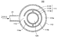
제 1 구성예에 있어서의 스위블 구조의 접속부(100)는 타워(2)의 축방향으로 연장하여 설치된 관상 부재(111)와, 관상 부재(111)를 둘러싸도록 설치된 제 1 재킷(112) 및 제 2 재킷(115)을 갖고 있고, 이들에 의해, 나셀(4)측의 유압 펌프(8)로부터 타워(2)측의 유압 모터(10)에 향하는 고압유가 흐르는 제 1 유로(121)와, 유압 모터(10)로부터 유압 펌프(8)에 향하는 저압유가 흐르는 제 2 유로(122)가 형성된다.The connecting
관상 부재(111)는 이중관 구조로 되어 있고, 외관(111A)과 내관(111B)과 격벽(11C)으로 이루어진다. 격벽(11C)은 외관(111A)과 내관(111B)으로 형성되는 환상의 공간을 둘레 방향으로 구획하고, 복수의 호 형상 유로(114a, 114b)를 형성한다. 또한, 도 4b에는, 호 형상 유로(114a, 114b)가 2개 형성되어 있는 예를 나타냈지만, 이것보다 많은 호 형상 유로가 형성되어도 좋다.The
제 1 재킷(112)은 관상 부재(111)의 외관(111A)의 외주측에 설치된다. 제 1 재킷(112)의 내벽면과 외관(111A)의 외벽면으로 형성되는 환상 유로(112a)는 제 1 재킷(112)의 외주에 접속되는 고압측 제 1 배관(31)에 연통하고 있다. 또한, 환상 유로(112a)는 외관(111A)에 설치된 제 1 연통구(113)를 통해서, 호 형상 유로(114a)에 연통하고 있다. 또한, 이 호 형상 유로(114a)는 외관(111A)의 외주에 접속되는 고압측 제 2 배관(32)에 연통하고 있다. 그리고, 환상 유로(112a) 및 호 형상 유로(114a)에 의해 제 1 유로(121)가 형성된다. 고압측 제 1 배관(31)으로부터 제 1 유로(121)에 공급되는 고압유는 환상 유로(112a), 제 1 연통구(113), 호 형상 유로(114a)를 통과하고, 고압측 제 2 배관(32)에 송출된다.The
제 2 재킷(115)은 관상 부재(111)의 외관(111A)의 외주측에 설치되고, 제 1 재킷(112)보다도 나셀(4)측에 배치되어 있다. 제 2 재킷(115)은 볼트(125)에 의해 제 1 재킷(112)에 체결되어 있다. 관상 부재(111)의 호 형상 유로(114b)는 외관(111A)의 외주에 접속되는 저압측 제 2 배관(33)에 연통하고 있다. 또한, 호 형상 유로(114b)는 외관(111A)에 설치된 제 2 연통구(116)를 통해서, 제 2 재킷(115)의 내벽면과 외관(111A)의 외벽면으로 형성되는 환상 유로(115a)에 연통하고 있다. 또한, 환상 유로(115a)는 제 2 재킷(115)의 외주에 접속되는 저압측 제 1 배관(34)에 연통하고 있다. 그리고, 호 형상 유로(114b) 및 환상 유로(115a)에 의해 제 2 유로(122)가 형성된다. 저압측 제 2 배관(33)으로부터 제 2 유로(122)에 공급되는 저압유는 호 형상 유로(114b), 제 2 연통구(116), 환상 유로(115a)를 통해서, 저압측 제 1 배관(34)에 송출된다.The
제 1 재킷(112) 및 제 2 재킷(115)은 나셀(4)측에 지지되어 있다. 한편, 관상 부재(111)는 타워(2)측에 지지되어 있다. 또한, 제 1 재킷(112)과 외관(111A) 사이에는 액밀성을 확보하도록 베어링(118)이 설치되고, 제 2 재킷(115)과 외관(111A) 사이에는 액밀성을 확보하도록 베어링(119)이 설치되어 있다. 이들 베어링(118, 119)에 의해, 제 1 재킷(112) 및 제 2 재킷(113)은 관상 부재(111)에 대하여 상대적으로 선회 가능하게 설치되어 있다.The
상기 구성에 의해, 나셀(4)측의 유압 펌프(8)로부터 타워(2)측의 유압 모터(10)로 향하는 고압유 및 유압 펌프(8)로부터 유압 모터(10)를 향하는 저압유의 흐름을 확보하면서, 제 1 배관[고압측 제 1 배관(31), 저압측 제 1 배관(34)]과 제 2 배관[고압측 제 2 배관(32), 저압측 제 2 배관(33)]과의 상대적인 선회를 가능하게 하고 있다. 따라서, 나셀(4)이 선회해도, 나셀(4) 내의 유압 펌프(8)와 타워(2) 내의 유압 모터(10) 사이의 고압유 및 저압유의 교환을 접속부(100)를 통해서 행할 수 있다.With this configuration, the flow of high pressure oil directed from the
또한, 상술한 제 1 구성예에 있어서, 관상 부재(111)의 내관(111B)으로 둘러싸이는 공간을 케이블용 배관(124)으로서 사용하는 것이 바람직하다. 케이블용 배관(124)은 나셀(4)측으로부터 타워(2)측까지 연장설치되는 케이블(125)을 수용하는 배관이다. 여기서, 케이블용 배관(124)에는, 유압 펌프(8) 등과 같이 나셀(4) 내에 배치되는 전기 이용 기기에의 전력 공급에 사용되는 전력 케이블 또는 제어에 사용되는 통신 케이블, 나셀(4)측에 설치되는 각종 계측 기기에 접속되는 신호 케이블, 또는 회전 블레이드(6B)나 나셀(4)에의 낙뢰시에 전기를 빠져나가게 하는 피뢰용 케이블 등의 케이블(125)이 수용된다.In addition, in the above-mentioned 1st structural example, it is preferable to use the space enclosed by the
이와 같이, 내관(111B)으로 둘러싸이는 공간을 케이블용 배관(124)으로서 사용함으로써, 나셀(4)이 선회했을 경우라도, 케이블(125)이 손상하는 것을 방지할 수 있다.Thus, by using the space enclosed by the
도 6은 본 발명의 실시형태에 관한 풍력 발전 장치에 적용되는 스위블 구조의 제 2 구성예를 도시하는 도면이다.It is a figure which shows the 2nd structural example of the swivel structure applied to the wind turbine generator which concerns on embodiment of this invention.
제 2 구성예에 있어서의 스위블 구조의 접속부(100')는 나셀(4)에 수납된 유압 펌프(8)와, 타워(2) 내에 설치된 유압 모터(10)를, 제 1 이중관(130) 및 제 2 이중관(140)을 사용해서 접속하고 있다.The connecting
제 1 이중관(130)은 나셀(4)에 고정되고, 제 2 이중관(140)은 타워(2)에 고정되고, 제 1 이중관(130) 및 제 2 이중관(140)은 상대적으로 회전 가능하게 구성되어 있다.The first
이하에, 제 1 이중관(130) 및 제 2 이중관(140)의 구체적인 구성을 설명한다.Below, the specific structure of the 1st double pipe |
제 1 이중관(130)은 플랜지부에 있어서 볼트(135)로 체결된 상측 부재(131) 및 하측 부재(133)에 의해 구성되어 있다. 또한, 상측 부재(131)와 하측 부재(133)의 접합면에는 베어링(136)이 설치되고, 액밀성이 유지되어 있다. 상측 부재(131)는, 그 상부에 있어서 유압 펌프(8)의 토출측에, 고압측 제 1 배관(31)(도 1 참조)을 통해서 접속되는 고압유 입구를 갖는다. 하측 부재(133)는, 상측 부재(131)에 접합된 플랜지부에서 하방에 축 늘어지는 내주측 원통부와 외주측 원통부를 갖고, 이 외주측 원통부의 측면에는 유압 펌프(8)의 흡입측에, 저압측 제 1 배관(34)(도 1 참조)을 통해서 접속되는 저압유 출구가 설치되어 있다.The 1st double pipe |
그리고, 상측 부재(131)와 하측 부재(133)의 일부(내주측 원통부)에 의해, 제 1 이중관(130)의 제 1 내측 배관(132)이 형성되어 있다. 또한, 하측 부재(133)의 일부(외주측 원통부)에 의해, 제 1 이중관(130)의 제 1 외측 배관(134)이 형성되어 있다.And the 1st inner side pipe |
한편, 제 2 이중관(140)은 제 2 내측 배관(142) 및 이 제 2 내측 배관(142)의 외주에 설치되는 제 2 외측 배관(144)을 갖는다. 또한, 제 2 이중관(140)의 하부에는, 고압측 제 2 배관(32)(도 1 참조)에 접속되는 고압유 출구가 설치되어 있다. 또한, 제 2 이중관(140)의 측면에는, 저압측 제 2 배관(33)(도 1 참조)에 접속되는 저압유 입구가 설치되어 있다.On the other hand, the second
그리고, 제 1 이중관(130)은 제 2 이중관(140)에 회전 가능하게 끼워맞춰져 있다. 이와 같이 끼워맞춰진 제 1 이중관(130) 및 제 2 이중관(140)에 의해, 나셀(4)측으로부터 타워(2)측으로 향하는 고압유가 흐르는 제 1 유로(151)와, 타워(2)측으로부터 나셀(4)측으로 향하는 저압유가 흐르는 제 2 유로(152)가 형성된다.The first
또한, 제 1 내측 배관(132)의 내벽면과 제 2 내측 배관(142)의 외벽면 사이에는 내측 베어링(155)이 설치되어 있다. 또한, 제 1 외측 배관(134)의 내벽면과 제 2 외측 배관(144)의 외벽면 사이에는 외측 베어링(156)이 설치되어 있다.In addition, an
상기 구성의 풍력 발전 장치(100)에 따르면, 나셀(4)측에 지지된 제 1 이중관(130)을 회전 가능하게 제 2 이중관(140)에 접속했으므로, 나셀(4)이 선회해도, 나셀(4) 내의 유압 펌프(8)와 타워(2) 내의 유압 모터(10) 사이의 고압유 및 저압유의 교환을 제 1 이중관(130)과 제 2 이중관(140)을 통해서 행할 수 있다.According to the
도 7은 본 발명의 실시형태에 관한 풍력 발전 장치에 적용되는 스위블 구조의 제 3 구성예를 도시하는 도면이다.It is a figure which shows the 3rd structural example of the swivel structure applied to the wind turbine generator which concerns on embodiment of this invention.
제 3 구성예에 있어서의 스위블 구조의 접속부(100")는 타워(2)의 축방향으로 연장하여 설치된 이중관(160)과, 이중관(160)을 둘러싸도록 설치된 제 1 재킷(164) 및 제 2 재킷(166)을 갖고 있고, 이들에 의해 나셀(4)측의 유압 펌프(8)로부터 타워(2)측의 유압 모터(10)로 향하는 고압유가 흐르는 제 1 유로(171)와, 유압 모터(10)로부터 유압 펌프(8)에 향하는 저압유가 흐르는 제 2 유로(172)가 형성된다.The connecting
이중관(160)은 내관(160A)과 외관(160B)으로 이루어지고, 내관(160A)의 내부에는 내측 유로가 형성되고, 내관(160A) 및 외관(160B)에 의해 외측 유로가 형성되어 있다.The
제 1 재킷(164)은 내관(160A)의 외주측에 설치된다. 제 1 재킷(164)의 내벽면과 내관(160A)의 외벽면으로 형성되는 환상 유로(164a)는 제 1 재킷(164)의 외주에 접속되는 고압측 제 1 배관(31)에 연통하고 있다. 또한, 환상 유로(164a)는 내관(160A)에 설치된 제 1 연통구(161)를 통해서, 내측 유로에 연통하고 있다. 또한, 이 내측 유로는 내관(160A)의 하단부에 접속되는 고압측 제 2 배관(32)에 연통하고 있다. 그리고, 환상 유로(164a) 및 내측 유로에 의해 제 1 유로(171)가 형성된다. 고압측 제 1 배관(31)으로부터 제 1 유로(171)에 공급되는 고압유는 환상 유로(164a), 제 1 연통구(161), 내측 유로를 통과하고, 고압측 제 2 배관(32)에 송출된다.The
제 2 재킷(166)은 외관(160B)의 외주측에 설치되고, 제 1 재킷(164)보다도 타워(2)측에 배치되어 있다. 제 2 재킷(166)은 볼트(175)에 의해 제 1 재킷(164)에 체결되어 있다. 외측 유로는 외관(160B)의 외주에 접속되는 저압측 제 2 배관(33)에 연통하고 있는 동시에, 제 2 재킷(166)의 내벽면과 내관(160A)의 외벽면 사이에 형성되는 환상 유로(166a)에 연통하고 있다. 환상 유로(166a)는 제 2 재킷(166)의 외주에 접속되는 저압측 제 1 배관(34)에 연통하고 있다. 그리고, 외측 유로 및 환상 유로(166a)에 의해 제 2 유로(172)가 형성된다. 저압측 제 2 배관(33)으로부터 제 2 유로(172)에 공급되는 저압유는 외측 유로, 환상 유로(166a)를 통해서, 저압측 제 1 배관(34)에 송출된다.The
제 1 재킷(164) 및 제 2 재킷(166)은 나셀(4)측에 지지되어 있다. 한편, 이중관(160)은 타워(2)측에 지지되어 있다. 제 1 재킷(164)과 이중관(160)의 내관(160A) 사이에는 액밀성을 확보하도록 베어링(176)이 설치되어 있다. 또한, 제 2 재킷(166)과 내관(160A) 사이에는 액밀성을 확보하도록 베어링(176)이 설치되고, 제 2 재킷(166)과 외관(160B) 사이에는 액밀성을 확보하도록 베어링(177)이 설치되어 있다. 이들의 베어링(176, 177)에 의해, 제 1 재킷(164) 및 제 2 재킷(166)은 이중관(160)에 대하여 상대적으로 선회 가능하게 설치되어 있다.The
상기 구성에 의해, 나셀(4)측의 유압 펌프(8)로부터 타워(2)측의 유압 모터(10)로 향하는 고압유 및 유압 펌프(8)로부터 유압 모터(10)를 향하는 저압유의 흐름을 확보하면서, 제 1 배관[고압측 제 1 배관(31), 저압측 제 1 배관(34)]과 제 2 배관[고압측 제 2 배관(32), 저압측 제 2 배관(33)]과의 상대적인 선회를 가능하게 하고 있다. 따라서, 나셀(4)이 선회해도, 나셀(4) 내의 유압 펌프(8)와 타워(2) 내의 유압 모터(10) 사이의 고압유 및 저압유의 교환을 접속부(100)를 통해서 행할 수 있다.With this configuration, the flow of high pressure oil directed from the
상술한 제 1 실시형태에 따르면, 작동유의 냉각에 사용되는 냉매를 타워(2)의 기부(2A) 주변의 해수와 열교환하는 것에 의해 냉각하도록 했으므로, 공냉보다 고효율로 냉매를 냉각할 수 있다.According to the first embodiment described above, the refrigerant used for cooling the working oil is cooled by heat exchange with seawater around the
또한, 작동유 라인(30)을 나셀(4)측에 지지되는 제 1 배관과, 타워(2)측에 지지되는 제 2 배관으로 분할하고, 스위블 구조를 갖는 접속부(100, 100'、100")에 의해, 제 1 배관과 제 2 배관이 상대적으로 선회 가능으로 되도록 접속했으므로, 나셀(4)이 선회해도, 나셀(4)측의 제 1 배관과 타워(2)측의 제 2 배관 사이에서 유체의 교환을 원활하게 행할 수 있다.In addition, the
또한, 유압 모터(10)가 타워(2)의 선단부(2B)와 기부(2A) 사이에 배치되도록 했으므로, 작동유 라인(30)이 타워(2)측까지 연장설치되도록 되고, 타워(2) 내로 작동유와 냉매를 열교환시킬 수 있기 때문에, 작동유를 냉각하기 위한 냉매 라인(40)을 나셀(4)까지 연장설치할 필요가 없어진다. 따라서, 냉매 라인(40)에 의해 나셀 높이까지 냉매를 퍼 올릴 경우에 비해, 펌프(47)의 동력을 작게 할 수 있고, 또한 펌프(47)를 소형화하는 것도 가능하다.In addition, since the
여기서, 도 1에 도시한 제 1 실시형태에 관한 풍력 발전 장치(1)의 변형예에 대해서 설명한다. 또한, 이하의 변형예에 있어서는, 도 1에 도시한 제 1 실시형태와 다른 구성만 설명한다.Here, the modification of the
도 8에 도시하는 제 1 변형예는 트랜스실 냉각기(55)와 타워 냉각기(54)를 직렬로 접속하는 냉매 분기 라인(44')을 설치한 구성으로 하고 있다. 냉매 분기 라인(44')은 냉매 이송 라인(41)으로부터 분기되어 냉매 복귀 라인(42)에 합류되도록 구성되어 있고, 이 냉매 분기 라인(44')에 트랜스실 냉각기(55)와 타워 냉각기(54)를 직렬로 설치하고 있다. 냉매 분기 라인(44')을 흐르는 냉매는 트랜스실 냉각기(55)에 의해 트랜스실(21) 내의 공기와 열교환되어서 트랜스실(21) 내의 공기를 냉각한다. 계속해서, 트랜스실 냉각기(55)로부터 배출된 냉매는 타워 냉각기(54)에 공급되고, 타워(2) 내의 공기와 열교환되어서 타워(2) 내의 공기를 냉각한다. 이들의 냉각기를 거친 냉매는 주 열교환기(51)에 복귀된다. 또한, 이들의 냉각기는 타워 냉각기(54), 트랜스실 냉각기(55)의 순서대로 냉매 분기 라인(44')에 설치해도 좋고, 냉각기의 배치 순서는 특별히 한정되는 것이 아니다.The 1st modified example shown in FIG. 8 is set as the structure provided with the refrigerant branch line 44 'which connects the
이와 같이, 복수의 열발생원을 직렬로 접속하는 냉매 라인을 구비함으로써, 배관 구성을 간소화할 수 있다.Thus, the piping structure can be simplified by providing the refrigerant line which connects several heat generating sources in series.
도 9에 도시하는 제 2 변형예는 주 열교환기(51)를 복수대 설치한 구성으로 되어 있다. 또한, 도 9에는 2개의 주 열교환기(51a, 51b)를 설치한 예를 나타내고 있지만, 설치 대수는 한정되지 않는다. 냉매 복귀 라인(42)은 주 열교환기(51a, 51b)의 입구측에서 2개로 분기되고, 한쪽의 라인은 주 열교환기(51a)에 접속되고, 다른쪽의 라인은 주 열교환기(51B)에 접속된다. 각 라인에는, 냉매 순환용의 펌프(47a, 47b)가 각각 설치되어 있다. 주 열교환기(51a, 51b)로 냉각된 냉매가 흐르는 각 라인은 주 열교환기(51a, 51b)의 출구측에서 합류하고, 냉매 이송 라인(41)에 접속되어 있다. 이와 같이, 복수의 주 열교환기(51a, 51b)를 설치함으로써, 냉각 기능을 높게 할 수 있다. 또한, 주 열교환기의 설치 대수는 냉각 대상이 되는 열발생원의 총발열량으로부터 결정되는 것이 바람직하다.9 is the structure which provided two
도 10에 도시하는 제 3 변형예는, 냉매 라인(40)에 접속되는 냉매 탱크(49)가 타워(2)의 내부에 배치되는 동시에, 상기 냉매 탱크(49)가 타워내 공간에 대하여 밀폐된 구성을 갖고 있다. 이와 같이, 냉매 탱크(49)를 타워(2)의 내부에 배치하고, 또한 냉매 탱크(49)가 타워(2) 내의 공간에 대하여 밀폐되도록 했으므로, 예를 들어 냉매 탱크(49)를 냉매 라인의 하방에 배치하는 등 냉매 탱크(49)의 배치를 자유롭게 할 수 있다. 또한, 도 10에는 냉매 탱크(49)를 1대 설치한 경우를 도시하고 있지만, 복수대의 냉매 탱크(49)를 설치해도 좋고, 도 1에 도시하는 개방형의 냉매 탱크(48)와 조합해서 사용해도 된다.In the third modification shown in FIG. 10, a
[제 2 실시형태] [Second Embodiment]
다음에, 도 11을 참조하여 제 2 실시형태에 관한 풍력 발전 장치에 대해서 설명한다. 도 11은 본 발명의 제 2 실시형태에 관한 풍력 발전 장치의 전체 구성을 도시하는 도면이다. 또한, 본 실시형태에 관한 풍력 발전 장치(1)는 유압 트랜스미션 및 작동유 라인(30)의 구성이 다른 점을 제외하면, 제 1 실시형태에 관한 풍력 발전 장치(1)와 동일하다. 따라서, 여기에서는, 제 1 실시형태와 다른 점을 중심으로 설명하는 것으로 하고, 도 11에서는 풍력 발전 장치(1)와 공통되는 개소에는 동일한 도면부호를 부여하고, 그 설명을 생략한다. 또한, 도 11에 있어서는, 나셀 선회 기구(19) 및 요 구동 기구(13)를 생략하고 있다.Next, with reference to FIG. 11, the wind power generator which concerns on 2nd Embodiment is demonstrated. It is a figure which shows the whole structure of the wind turbine generator which concerns on 2nd Embodiment of this invention. In addition, the
본 실시형태에 관한 풍력 발전 장치(1)에서는, 유압 모터(10) 및 발전기(12)는 나셀(4)측에 지지되어 있다. 또한, 중간 열교환기(52)는 타워측(2)에 지지되어 있다.In the
작동유 라인(30)은 유압 펌프(8)와 유압 모터(10) 사이에서 작동유를 순환시키는 작동유 순환 라인과, 작동유 순환 라인에 병행으로 접속된 작동유 분기 라인(38)을 갖는다.The
작동유 순환 라인은 유압 펌프(8)의 작동유 출구측과 유압 모터(10)의 작동유 입구측을 접속하는 고압유 라인(36)과, 유압 모터(10)의 작동유 출구측과 유압 펌프(8)의 작동유 입구측을 접속하는 저압유 라인(37)으로 이루어진다.The hydraulic oil circulation line includes the high
작동유 분기 라인(38)은 저압유 라인(37)으로부터 분기되어, 스위블 구조를 갖는 접속부(100)를 통해서, 나셀(4)측으로부터 타워(2)측까지 연장설치되어서, 타워(2)측의 중간 열교환기(52)의 입구측에 접속된다. 또한, 중간 열교환기(52)의 출구측에 접속되는 작동유 분기 라인(38)은 접속부(100)를 통해서, 타워(2)측으로부터 나셀(4)측까지 연장설치되어서, 저압유 라인(37)에 합류된다. 또한, 접속부(100)에는, 제 1 실시형태에서 설명한 구성을 채용할 수 있다.The hydraulic
저압유 라인(37)으로부터 분기된 저압유는 작동유 분기 라인(38)을 통과해서 중간 열교환기(52)에 도입되어, 중간 열교환기(52)에서 냉매에 의해 냉각된 후, 작동유 분기 라인(38)을 통과해서 저압유 라인(37)에 복귀된다.The low pressure oil branched from the low
이와 같이, 유압 모터(8)가 나셀(4)측에 지지되어, 저압유 라인(37)으로부터 분기한 작동유 분기 라인(37)이 타워(2)측의 중간 열교환기(52)에 접속되도록 했으므로, 작동유 유량이 많은 작동유 라인(30)을 짧게 할 수 있고, 한편 접속부(100)를 통과하는 작동유 유량을 적게 할 수 있다. 이에 의해 배관 구조를 간소화하는 것이 가능해진다. 또한, 작동유 분기 라인(38)은 저압유 라인(37)으로부터 분기시키고 있기 때문에, 작동유 분기 라인(38) 및 접속부(100)를 내압성이 낮은 배관으로 구성할 수 있고, 비용 저감이 도모된다.In this way, the
또한, 본 실시형태에 관한 풍력 발전 장치(1)는 공냉에 의해 발전기(12)를 냉각하는 발전기 쿨러(53')를 갖고 있어도 좋다.In addition, the
이 경우, 나셀(4)의 외주측에 외기를 도입하는 덕트(81)가 설치되어 있다. 덕트(81)는 흡기구를 갖고 있고, 나셀(4)의 벽면에 일체적으로 형성되어 있어도 된다. 이때, 외기의 도입을 촉진하기 위해서, 덕트(81) 내에 팬(82)을 설치하는 것이 바람직하다.In this case, the
덕트(81)에서 취입한 공기는 공기 배관(83)을 통해서 나셀(4) 내에 유도된다. 공기 배관(83)에는 발전기 쿨러(53')가 설치되어 있다. 발전기 쿨러(53')는, 예를 들어 발전기(12)의 주위에 설치된 냉각 재킷으로서 구성되고, 냉각 재킷의 외주를 덕트(81)에서 취입한 공기가 흐르는 것에 의해 발전기(12)를 냉각한다. 냉각 후의 공기는 공기 배관(83)을 통과해서 나셀 외부로 배기된다.Air blown from the
또한, 덕트(81)에서 취입한 공기는 나셀(4) 내의 다른 열발생원의 냉각에 사용할 수도 있다. 예를 들어, 나셀(4) 내의 공기를 냉각하는 나셀 냉각기(도시하지 않음)의 냉각에 사용할 수 있다. 이와 같이, 타워(2) 내의 열발생원의 냉각에는 주로 수냉을 사용하고, 나셀(4) 내의 열발생원에는 공냉을 사용함으로써, 풍력 발전 장치(1)의 열발생원의 효율적인 냉각이 가능해진다.Moreover, the air blown in the
[제 3 실시형태] [Third embodiment]
계속해서, 도 12를 참조하여, 제 3 실시형태에 관한 풍력 발전 장치에 대해서 설명한다. 도 12는 본 발명의 제 3 실시형태에 관한 풍력 발전 장치의 전체 구성을 도시하는 도면이다.Next, with reference to FIG. 12, the wind power generator which concerns on 3rd Embodiment is demonstrated. It is a figure which shows the whole structure of the wind turbine generator which concerns on 3rd Embodiment of this invention.
또한, 본 실시형태에 관한 풍력 발전 장치(1)는 유압 트랜스미션 및 작동유 라인(30)의 구성이 다른 점을 제외하면, 제 1 실시형태에 관한 풍력 발전 장치(1)와 동일하다. 따라서, 여기에서는, 제 1 실시형태와 다른 점을 중심으로 설명하는 것으로 하고, 도 12에서는 풍력 발전 장치(1)와 공통되는 개소에는 동일한 도면부호를 부여하고, 그 설명을 생략한다. 또한, 도 12에 있어서는, 나셀 선회 기구(19) 및 요 구동 기구(13)를 생략하고 있다.In addition, the
본 실시형태에 관한 풍력 발전 장치(1)에서는, 유압 모터(10) 및 발전기(12)는 나셀(4)의 내부에 배치되어 있다. 또한, 중간 열교환기(52)도 나셀(4) 내에 배치되어 있다.In the
작동유 라인(30)은 유압 펌프(8)와 유압 모터(10) 사이에서 작동유를 순환시키는 작동유 순환 라인과, 작동유 순환 라인에 병행으로 접속된 작동유 분기 라인(38')을 갖고 있고, 어느 라인도 나셀(4) 내에 배치되어 있다.The
작동유 순환 라인은 유압 펌프(8)의 작동유 출구측과 유압 모터(10)의 작동유 입구측을 접속하는 고압유 라인(36)과, 유압 모터(10)의 작동유 출구측과 유압 펌프(8)의 작동유 입구측을 접속하는 저압유 라인(37)으로 이루어진다.The hydraulic oil circulation line includes the high
작동유 분기 라인(38')은 저압유 라인(37)으로부터 분기되어, 나셀(4) 내의 중간 열교환기(52)의 입구측에 접속된다. 또한, 중간 열교환기(52)의 출구측에 접속되는 작동유 분기 라인(38')은 저압유 라인(37)에 합류된다.The hydraulic oil branch line 38 'is branched from the low
냉매 라인(40)은, 스위블 구조를 갖는 접속부(100)를 통해서, 주 열교환기(51)와 중간 열교환기(52) 사이에 접속되는 냉매 이송 라인(41)과, 마찬가지로 접속부(100)를 통해서, 중간 열교환기(52)와 주 열교환기(51) 사이에 접속되는 냉매 복귀 라인(42)을 포함하고 있다. 또한, 접속부(100)에는, 제 1 실시형태에서 설명한 구성을 채용할 수 있다.The
주 열교환기(51)에 의해 해수로 냉각된 냉매는 냉매 이송 라인(41)을 통과해서 중간 열교환기(52)에 공급되고, 중간 열교환기(52)에서 작동유와 열교환됨으로써 작동유를 냉각한 후, 냉매 복귀 라인(42)을 통과해서 주 열교환기(51)에 복귀된다.The refrigerant cooled by sea water by the main heat exchanger (51) passes through the refrigerant transfer line (41), is supplied to the intermediate heat exchanger (52), and after cooling the hydraulic fluid by heat exchange with the hydraulic oil in the intermediate heat exchanger (52), The refrigerant is returned to the
이와 같이, 유압 모터(8) 및 발전기(10)는 나셀(4)의 내부에 배치되고, 나셀(4)측에 지지되는 중간 열교환기(52)에 접속부(100)를 통해서 냉매 라인(40)이 접속되도록 했으므로, 접속부(100)를 내압성이 낮은 배관으로 구성할 수 있고, 비용 저감이 도모된다.In this way, the
또한, 냉매 라인(40)은 냉매 이송 라인(41)의 나셀(4)측으로부터 분기되어, 냉매 복귀 라인(42)의 나셀(4)측에 합류되는 냉매 분기 라인(43')을 포함하고 있어도 된다. 이 냉매 분기 라인(43')에는, 발전기(12)를 냉각하는 발전기 쿨러(53)가 설치된다. 발전기 쿨러(53)는, 예를 들어 발전기(12)의 주위에 설치된 냉각 재킷으로서 구성된다. 발전기 쿨러(53)에서는, 냉매 분기 라인(43')으로부터 공급되는 냉매와의 열교환에 의해 발전기(12)를 냉각하게 되어 있다.In addition, the
[제 4 실시형태] [Fourth Embodiment]
마지막으로, 도 13을 참조하여, 제 4 실시형태에 관한 풍력 발전 장치에 대해서 설명한다. 도 13은 본 발명의 제 4 실시형태에 관한 풍력 발전 장치의 전체 구성을 도시하는 도면이다.Finally, with reference to FIG. 13, the wind power generator which concerns on 4th Embodiment is demonstrated. It is a figure which shows the whole structure of the wind turbine generator which concerns on 4th Embodiment of this invention.
본 실시형태에 관한 풍력 발전 장치(1)는 냉매 라인(40)을 구비하지 않고, 유압 트랜스미션의 작동유를 해수에서 직접 냉각하는 구성으로 되어 있다. 또한, 본 실시형태에 관한 풍력 발전 장치(1)에서는, 유압 트랜스미션, 작동유 라인(30) 및 냉매 라인(40)의 구성을 제외한 다른 구성에 대해서는, 제 1 실시형태에 관한 풍력 발전 장치(1)와 동일하기 때문에 그 상세한 설명을 생략한다. 또한, 도 13에 있어서는, 나셀 선회 기구(19) 및 요 구동 기구(13)를 생략하고 있다.The
본 실시형태에 관한 풍력 발전 장치(1)에서는, 유압 모터(10) 및 발전기(12)는 나셀(4)의 내부에 배치되어 있다.In the
작동유 라인(30)은 유압 펌프(8)와 유압 모터(10) 사이에서 작동유를 순환시키는 작동유 순환 라인과, 작동유 순환 라인에 병행으로 접속된 작동유 분기 라인(70)을 갖고 있고, 어느 라인도 나셀(4) 내에 배치되어 있다.The
작동유 순환 라인은, 유압 펌프(8)의 작동유 출구측과 유압 모터(10)의 작동유 입구측을 접속하는 고압유 라인(36)과, 유압 모터(10)의 작동유 출구측과 유압 펌프(8)의 작동유 입구측을 접속하는 저압유 라인(37)으로 이루어진다.The hydraulic oil circulation line includes the high
작동유 분기 라인(70)은 나셀(4)측에 지지되는 제 1 배관(71, 74)과, 타워(2)측에 지지되는 제 2 배관(72, 73)을 갖고 있다. 또한, 작동유 분기 라인(70)은 저압유 라인(37)에 병행으로 배치되는 것이 바람직하다. 또한, 작동유 분기 라인(70)에는, 분기 라인(70)의 작동유의 흐름을 형성하는 펌프(71)가 설치되어 있다.The hydraulic
제 1 배관(71)과 제 2 배관(72)은 스위블 구조를 갖는 접속부(100)에 의해 상대적으로 선회 가능하게 접속되어 있다. 마찬가지로, 제 1 배관(73)과 제 2 배관(74)은 접속부(100)에 의해 상대적으로 선회 가능하게 접속되어 있다. 이 접속부(100)에는, 제 1 실시형태에서 설명한 구성을 채용할 수 있다.The
저압 라인(37)으로부터 분기된 작동유는 제 1 배관(71), 접속부(100), 제 2 배관(72)을 순서대로 통과해서 주 열교환기(58)에 도입된다. 주 열교환기(58)에서는 해수와의 열교환에 의해 냉매가 냉각된다. 주 열교환기(58)로부터 배출되는 냉매는 제 2 배관(73), 접속부(100), 제 1 배관(74)을 순서대로 통과해서 저압 라인(37)에 복귀된다.The hydraulic oil branched from the
본 실시형태에 따르면, 작동유를, 타워 기부 주변의 해수, 호수, 하천수 또는 지하수로 이루어지는 냉수원과 열교환하는 것에 의해 냉각하도록 했으므로, 공냉보다 고효율로 작동유를 냉각할 수 있다.According to the present embodiment, the working oil is cooled by heat exchange with a cold water source consisting of seawater, a lake, river water or groundwater around the tower base, so that the working oil can be cooled more efficiently than air cooling.
또한, 작동유 순환 라인 및 작동유 분기 라인(70)중 한쪽을, 나셀(4)측에 지지되는 제 1 배관(71, 74)과, 타워(2)측에 지지되는 제 2 배관(72, 73)으로 분할하고, 스위블 구조를 갖는 접속부(100)에 의해, 제 1 배관(71, 74)과 제 2 배관(72, 73)이 상대적으로 선회 가능으로 되도록 접속했으므로, 나셀(4)이 선회해도, 나셀(4)측의 제 1 배관(71, 74)과 타워측의 제 2 배관(72, 73) 사이에서 유체의 교환을 원활하게 행할 수 있다.In addition, one of the hydraulic oil circulation line and the hydraulic
또한, 본 실시형태에 관한 풍력 발전 장치(1)는 공냉에 의해 발전기(12)를 냉각하는 발전기 쿨러(53')를 갖고 있어도 좋다.In addition, the
이 경우, 나셀(4)의 외주측에 외기를 도입하는 덕트(81)가 설치되어 있고, 덕트(81)로 취입한 공기는 공기 배관(83)을 통해서 나셀(4) 내에 유도된다. 공기 배관(83)에는 발전기 쿨러(53')가 설치되어 있다. 발전기 쿨러(53')는, 예를 들어 발전기(12)의 주위에 설치된 냉각 재킷으로서 구성되어, 냉각 재킷의 외주를 덕트(81)로 취입한 공기가 흐르는 것에 의해 발전기(12)를 냉각한다. 냉각후의 공기는 공기 배관(83)을 통과해서 나셀 외부에 배기된다.In this case, the
또한, 덕트(81)로 취입한 공기는 나셀(4) 내의 다른 열발생원의 냉각에 사용할 수도 있다. 예를 들어, 나셀(4) 내의 공기를 냉각하는 나셀 냉각기(도시하지 않음)의 냉각에 사용할 수 있다. 이와 같이, 타워(2) 내의 열발생원의 냉각에는 주로 수냉을 사용하고, 나셀(4) 내의 열발생원에는 공냉을 사용함으로써, 풍력 발전 장치(1)의 열발생원의 효율적인 냉각이 가능해진다.In addition, the air blown into the
이상, 본 발명의 실시형태에 대해서 상세하게 설명했지만, 본 발명은 이것에 한정되지 않고, 본 발명의 요지를 일탈하지 않는 범위에 있어서, 각종 개량이나 변형을 행해도 좋은 것은 말할 필요도 없다.As mentioned above, although embodiment of this invention was described in detail, this invention is not limited to this, Needless to say that various improvement and deformation may be performed in the range which does not deviate from the summary of this invention.
또한, 상술한 실시형태에서는, 재생 에너지형 발전 장치의 구체예로서 풍력 발전 장치(1)에 대해서 설명했지만, 본 발명은 풍력 발전 장치 이외의 재생 에너지형 발전 장치에도 적용할 수 있다.In addition, although the above-mentioned embodiment demonstrated the
예를 들어, 조류, 해류 또는 하류를 이용한 발전 장치이며, 타워가 기단부로부터 선단부를 향해서 해중 또는 수중을 연직 방향 하방으로 연장하는 동시에, 회전 블레이드에 의해 조류, 해류 또는 하류를 받는 것에 의해 주축이 회전하도록 발전 장치에 본 발명을 적용해도 좋다.For example, a power generation device using tidal currents, currents, or downstream, wherein the tower is rotated by receiving a tidal current, current or downstream by a rotary blade while extending the sea or water vertically downward from the proximal end toward the distal end. You may apply this invention to a power generation apparatus so that it may be.
1 : 풍력 발전 장치 2 : 타워
2A : 타워 기부 2B : 타워 선단부
4 : 나셀 6 : 로터
6A : 허브 6B : 회전 블레이드
8 : 유압 펌프 10 : 유압 모터
12 : 발전기 14 : 주축
15 : 주축 베어링 21 : 트랜스실
30 : 작동유 라인 31 : 고압측 제 1 배관
32 : 고압측 제 2 배관 33 : 저압측 제 2 배관
34 : 저압측 제 1 배관 36 : 고압유 라인
37 : 저압유 라인 38 : 작동유 분기 라인
40 : 냉매 라인 41 : 냉매 이송 라인
42 : 냉매 복귀 라인 43, 44, 44'、45 : 냉매 분기 라인
51, 51'、58 : 주 열교환기 52 : 중간 열교환기
53 : 발전기 쿨러 54 : 타워 냉각기
55 : 트랜스실 냉각기 70 : 작동유 분기 라인
71, 74 : 제 1 배관 72, 73 : 제 2 배관
100, 100'、100" : 접속부1: wind power generator 2: tower
2A:
4: nacelle 6: rotor
6A:
8: hydraulic pump 10: hydraulic motor
12: generator 14: spindle
15: spindle bearing 21: transsil
30: hydraulic oil line 31: high pressure side first pipe
32: high pressure side second pipe 33: low pressure side second pipe
34 low pressure side
37: low pressure oil line 38: hydraulic oil branch line
40: refrigerant line 41: refrigerant transfer line
42:
51, 51 ', 58: main heat exchanger 52: intermediate heat exchanger
53: generator cooler 54: tower cooler
55 transsil cooler 70 hydraulic oil branch line
71, 74: first piping 72, 73: second piping
100, 100 '、 100 ": Connection
Claims (18)
타워와,
상기 타워의 선단부에 선회 가능하게 지지된 나셀과,
상기 나셀에 수납되어, 회전 블레이드와 함께 회전하는 주축과,
상기 나셀에 수납되어, 상기 주축의 회전에 의해 구동되는 유압 펌프와,
상기 유압 펌프로부터 공급되는 작동유에 의해 구동되는 유압 모터와,
상기 유압 모터에 연결된 발전기와,
상기 유압 펌프와 상기 유압 모터 사이에 설치되고, 상기 작동유가 흐르는 작동유 라인과,
중간 열교환기를 통해서 상기 작동유를 냉각하는 냉매가 순환하는 냉매 라인과,
상기 냉매를, 상기 타워 기부 주변의 해수, 호수, 하천수 또는 지하수로 이루어지는 냉수원과 열교환하는 것에 의해 냉각하는 주 열교환기를 구비하고,
상기 작동유 라인 및 상기 냉매 라인의 한쪽이, 상기 나셀측에 지지되는 제 1 배관과, 상기 타워측에 지지되는 제 2 배관과, 상기 제 1 배관과 상기 제 2 배관을 상대적으로 선회 가능하게 접속하는 접속부를 구비하는 것을 특징으로 하는
재생 에너지형 발전 장치.In the renewable energy type power generation device for generating electric power from renewable energy,
With towers,
A nacelle supported pivotally at the distal end of the tower,
A main shaft accommodated in the nacelle and rotating together with a rotating blade;
A hydraulic pump stored in the nacelle and driven by rotation of the main shaft;
A hydraulic motor driven by the hydraulic oil supplied from the hydraulic pump,
A generator connected to the hydraulic motor,
A hydraulic oil line installed between the hydraulic pump and the hydraulic motor, through which the hydraulic oil flows;
A refrigerant line through which a refrigerant for cooling the working oil circulates through an intermediate heat exchanger,
A main heat exchanger for cooling the refrigerant by heat exchange with a cold water source comprising sea water, lake, river water or ground water around the base of the tower,
One of the hydraulic oil line and the refrigerant line connects the first pipe supported on the nacelle side, the second pipe supported on the tower side, and the first pipe and the second pipe in a rotatable manner. Characterized in that it comprises a connecting portion
Renewable energy type generator.
상기 유압 모터는 상기 타워의 상기 선단부와 상기 기부 사이에 배치되고,
상기 작동유 라인이 상기 나셀내의 상기 유압 펌프로부터 상기 타워 내의 상기 유압 모터까지 연장설치되어 있고,
상기 작동유 라인은 상기 제 1 배관, 상기 제 2 배관 및 상기 접속부를 갖고,
상기 제 1 배관이 상기 유압 펌프에 접속되고, 상기 제 2 배관이 상기 유압 모터에 접속되어 있는 것을 특징으로 하는
재생 에너지형 발전 장치.The method of claim 1,
The hydraulic motor is disposed between the tip of the tower and the base,
The hydraulic oil line extends from the hydraulic pump in the nacelle to the hydraulic motor in the tower,
The hydraulic oil line has the first pipe, the second pipe and the connecting portion,
The first pipe is connected to the hydraulic pump, and the second pipe is connected to the hydraulic motor.
Renewable energy type generator.
상기 유압 모터는 상기 나셀측에 지지되는 한편, 상기 중간 열교환기는 상기 타워측에 지지되어 있고,
상기 작동유 라인은, 상기 유압 펌프와 상기 유압 모터 사이를 작동유가 순환하는 작동유 순환 라인과, 상기 작동유 순환 라인의 저압측으로부터 분기해서 상기 중간 열교환기를 통과해서 상기 작동유 순환 라인에 복귀되는 작동유 분기 라인을 포함하고,
상기 작동유 분기 라인은 상기 제 1 배관, 상기 제 2 배관 및 상기 접속부를 갖고,
상기 제 1 배관이 상기 작동유 순환 라인에 접속되고, 상기 제 2 배관이 상기 중간 열교환기에 접속되어 있는 것을 특징으로 하는
재생 에너지형 발전 장치.The method of claim 1,
The hydraulic motor is supported on the nacelle side, while the intermediate heat exchanger is supported on the tower side,
The hydraulic oil line includes a hydraulic oil circulation line through which hydraulic oil circulates between the hydraulic pump and the hydraulic motor, and a hydraulic oil branch line branched from the low pressure side of the hydraulic oil circulation line and passing through the intermediate heat exchanger to return to the hydraulic oil circulation line. Including,
The hydraulic oil branch line has the first pipe, the second pipe and the connection portion,
The first pipe is connected to the working oil circulation line, and the second pipe is connected to the intermediate heat exchanger.
Renewable energy type generator.
상기 유압 모터 및 상기 발전기는 상기 나셀의 내부에 배치되는 한편, 상기 중간 열교환기는 상기 나셀측에 지지되어 있고,
상기 냉매 라인은 상기 제 1 배관, 상기 제 2 배관 및 상기 접속부를 갖고,
상기 제 1 배관이 상기 중간 열교환기측에 접속되고, 상기 제 2 배관이 상기 주 열교환기측에 접속되어 있는 것을 특징으로 하는
재생 에너지형 발전 장치.The method of claim 1,
The hydraulic motor and the generator are disposed inside the nacelle, while the intermediate heat exchanger is supported on the nacelle side,
The refrigerant line has the first pipe, the second pipe and the connection portion;
The first pipe is connected to the intermediate heat exchanger side, and the second pipe is connected to the main heat exchanger side.
Renewable energy type generator.
상기 나셀측으로부터 상기 타워측으로 향하는 유체가 흐르는 제 1 유로와,
상기 타워측으로부터 상기 나셀측으로 향하는 유체가 흐르는 제 2 유로와,
하나 또는 복수의 상기 제 1 유로 및 하나 또는 복수의 상기 제 2 유로가 형성된 관상 부재와,
상기 관상 부재를 둘러싸도록 설치되고, 상기 제 1 유로에 설치된 제 1 연통구를 통해서 상기 제 1 배관에 연통한 환상 유로를 포함하는 제 1 재킷과,
상기 관상 부재를 둘러싸도록 설치되고, 상기 제 2 유로에 설치된 제 2 연통구를 통해서 상기 제 2 배관에 연통한 환상 유로를 포함하는 제 2 재킷을 더 구비하고,
상기 제 1 재킷 및 상기 제 2 재킷이 베어링을 통해서 상기 관상 부재에 상대적으로 선회 가능하게 설치되어 있는 것을 특징으로 하는
재생 에너지형 발전 장치.The method of claim 1,
A first flow path through which the fluid flowing from the nacelle side toward the tower side flows;
A second flow path through which fluid from the tower side to the nacelle flows;
A tubular member having one or a plurality of first flow paths and one or a plurality of second flow paths formed therein;
A first jacket provided to surround the tubular member, the first jacket including an annular flow passage communicating with the first pipe via a first communication port provided in the first flow passage;
And a second jacket provided to surround the tubular member, the second jacket including an annular flow passage communicating with the second pipe via a second communication port provided in the second flow passage,
The first jacket and the second jacket are provided so as to be able to pivot relative to the tubular member through a bearing.
Renewable energy type generator.
상기 관상 부재에는, 상기 1 유로 및 상기 제 2 유로의 또한 내측에, 상기 나셀측으로부터 상기 타워측에 연장설치되는 케이블을 수용하는 케이블용 배관이 설치되어 있는 것을 특징으로 하는
재생 에너지형 발전 장치.The method of claim 5, wherein
The tubular member is provided with a cable pipe for accommodating a cable extending from the nacelle side to the tower side further inside the first flow passage and the second flow passage.
Renewable energy type generator.
상기 냉매 라인에 물을 공급하는 물공급원과,
상기 물에 부동액이 첨가된 냉매를 상기 냉매 라인내에서 순환시키는 펌프를 더 구비하는 것을 특징으로 하는
재생 에너지형 발전 장치.The method of claim 1,
A water supply source for supplying water to the refrigerant line;
And a pump for circulating the refrigerant in which the antifreeze is added to the water in the refrigerant line.
Renewable energy type generator.
상기 물공급원이 상기 냉매를 저류하는 냉매 탱크이며,
상기 냉매 탱크는 상기 타워의 상부에 배치되는 동시에, 상기 냉매 탱크는 타워내 공간에 개방되어 있는 것을 특징으로 하는
재생 에너지형 발전 장치.The method of claim 7, wherein
The water supply source is a refrigerant tank for storing the refrigerant,
The coolant tank is disposed above the tower, and the coolant tank is open to a space in the tower.
Renewable energy type generator.
상기 물공급원이 상기 냉매를 저류하는 냉매 탱크이며,
상기 냉매 탱크는 상기 타워의 내부에 배치되는 동시에, 상기 냉매 탱크는 타워내 공간에 대하여 밀폐되어 있는 것을 특징으로 하는
기재의 재생 에너지형 발전 장치.The method of claim 7, wherein
The water supply source is a refrigerant tank for storing the refrigerant,
The coolant tank is disposed inside the tower, and the coolant tank is sealed to a space in the tower.
Renewable energy type generator of base material.
상기 주 열교환기를 수용하는 케이싱의 냉수원 입구에는, 상기 냉수원에 포함되는 이물질이 상기 케이싱 내부에 혼입하는 것을 방지하는 필터가 설치되어 있는 것을 특징으로 하는
재생 에너지형 발전 장치.The method of claim 1,
A cold water source inlet of the casing accommodating the main heat exchanger is provided with a filter that prevents foreign matter contained in the cold water source from entering the casing.
Renewable energy type generator.
상기 주 열교환기는 상기 타워가 설치되는 기초에 설치되어 있는 것을 특징으로 하는
재생 에너지형 발전 장치.The method of claim 1,
The main heat exchanger is installed on the base on which the tower is installed
Renewable energy type generator.
상기 열교환기의 전열관 주위에, 냉수원의 유속을 조정하는 유속 조정용 구조체가 배치되고,
상기 유속 조정용 구조체와 상기 전열관 사이의 거리의 상한이 상기 전열관에 있어서 소정의 열전달률이 얻어지는 거리에 기초하여 설정되고, 하한이 상기 전열관에 부착되는 이물질이 박리하는 거리에 기초하여 설정되는 것을 특징으로 하는
재생 에너지형 발전 장치.The method of claim 11,
Around the heat exchanger tube of the heat exchanger, a flow rate adjusting structure for adjusting the flow rate of the cold water source is disposed,
The upper limit of the distance between the flow rate adjusting structure and the heat transfer tube is set based on the distance at which a predetermined heat transfer rate is obtained in the heat transfer tube, and the lower limit is set based on the distance at which foreign matter adhered to the heat transfer tube peels off. doing
Renewable energy type generator.
상기 주 열교환기의 전열관 표면에 상기 냉수원을 분사하는 스프레이 노즐을 설치한 것을 특징으로 하는
재생 에너지형 발전 장치.The method of claim 11,
A spray nozzle for spraying the cold water source is provided on the surface of the heat exchanger tube of the main heat exchanger.
Renewable energy type generator.
상기 열교환기는 복수의 전열관을 갖는 다관식 열교환기인 것을 특징으로 하는
재생 에너지형 발전 장치.The method of claim 11,
The heat exchanger is a multi-tube heat exchanger having a plurality of heat transfer tubes
Renewable energy type generator.
상기 재생 에너지형 발전 장치는 풍력 발전 장치이며,
상기 타워가 상기 기단부로부터 상기 선단부를 향해서 연직 방향 상방으로 연장하는 동시에,
상기 회전 블레이드에 의해 바람을 받는 것에 의해 상기 주축이 회전하는
재생 에너지형 발전 장치.The method of claim 1,
The renewable energy type power generation device is a wind power generation device,
The tower extends vertically upward from the proximal end toward the distal end;
The main shaft rotates by being winded by the rotating blade
Renewable energy type generator.
상기 나셀 내에 수납되어, 상기 나셀의 주위로부터 도입한 공기에 의해 상기 발전기를 냉각하는 발전기 냉각기를 더 구비하는 것을 특징으로 하는
재생 에너지형 발전 장치.The method of claim 1,
And a generator cooler housed in the nacelle and cooling the generator by air introduced from the periphery of the nacelle.
Renewable energy type generator.
타워와,
상기 타워의 선단부에 선회 가능하게 지지된 나셀과,
상기 나셀에 수납되어, 회전 블레이드와 함께 회전하는 주축과,
상기 나셀에 수납되어, 상기 주축의 회전에 의해 구동되는 유압 펌프와,
상기 유압 펌프로부터 공급되는 작동유에 의해 구동되는 유압 모터와,
상기 유압 모터에 연결된 발전기와,
상기 유압 펌프와 상기 유압 모터 사이에 설치되고, 상기 작동유가 흐르는 작동유 순환 라인과,
상기 작동유를, 상기 타워 기부 주변의 해수, 호수, 하천수 또는 지하수로 이루어지는 냉수원과 열교환하는 것에 의해 냉각하는 주 열교환기를 구비하고,
상기 작동유 순환 라인 및 상기 작동유 순환 라인으로부터 분기되는 작동유 분기 라인의 한쪽이, 상기 나셀측에 지지되는 제 1 배관과, 상기 타워측에 지지되는 제 2 배관과, 상기 제 1 배관과 상기 제 2 배관을 상대적으로 선회 가능하게 접속하는 접속부를 갖는 것을 특징으로 하는
재생 에너지형 발전 장치.In the renewable energy type power generation device for generating electric power from renewable energy,
With towers,
A nacelle supported pivotally at the distal end of the tower,
A main shaft accommodated in the nacelle and rotating together with a rotating blade;
A hydraulic pump stored in the nacelle and driven by rotation of the main shaft;
A hydraulic motor driven by the hydraulic oil supplied from the hydraulic pump,
A generator connected to the hydraulic motor,
A hydraulic oil circulating line installed between the hydraulic pump and the hydraulic motor, through which the hydraulic oil flows;
A main heat exchanger for cooling the working oil by heat exchange with a cold water source comprising sea water, a lake, river water or ground water around the base of the tower,
One of the hydraulic oil branch lines branched from the hydraulic oil circulation line and the hydraulic oil circulation line includes a first pipe supported on the nacelle side, a second pipe supported on the tower side, the first pipe and the second pipe. Characterized in that it has a connecting portion for relatively rotatable connection
Renewable energy type generator.
상기 나셀 내에 수납되어, 상기 나셀의 주위로부터 도입한 공기에 의해 상기 발전기를 냉각하는 발전기 냉각기를 더 구비하는 것을 특징으로 하는
재생 에너지형 발전 장치.The method of claim 17,
And a generator cooler housed in the nacelle and cooling the generator by air introduced from the periphery of the nacelle.
Renewable energy type generator.
Applications Claiming Priority (5)
| Application Number | Priority Date | Filing Date | Title |
|---|---|---|---|
| WOPCT/JP2011/058647 | 2011-04-05 | ||
| PCT/JP2011/058647 WO2012137311A1 (en) | 2011-04-05 | 2011-04-05 | Renewable energy generator device |
| PCT/JP2011/068284 WO2013021488A1 (en) | 2011-08-10 | 2011-08-10 | Renewable energy type electric power generation device |
| WOPCT/JP2011/068284 | 2011-08-10 | ||
| PCT/JP2011/071673 WO2012137370A1 (en) | 2011-04-05 | 2011-09-22 | Regenerated energy electricity generation device |
Publications (1)
| Publication Number | Publication Date |
|---|---|
| KR20120139669A true KR20120139669A (en) | 2012-12-27 |
Family
ID=46968797
Family Applications (1)
| Application Number | Title | Priority Date | Filing Date |
|---|---|---|---|
| KR1020127010773A KR20120139669A (en) | 2011-04-05 | 2011-09-22 | Renewable energy type generating apparatus |
Country Status (7)
| Country | Link |
|---|---|
| US (1) | US8684682B2 (en) |
| EP (1) | EP2532890A4 (en) |
| KR (1) | KR20120139669A (en) |
| CN (1) | CN102822511A (en) |
| AU (1) | AU2011310939A1 (en) |
| IN (1) | IN2012DN03061A (en) |
| WO (3) | WO2012137370A1 (en) |
Families Citing this family (24)
| Publication number | Priority date | Publication date | Assignee | Title |
|---|---|---|---|---|
| US8541897B2 (en) * | 2009-09-01 | 2013-09-24 | University Of Southern California | Generation of electric energy using cable-supported windmills |
| US20130028729A1 (en) * | 2011-07-28 | 2013-01-31 | Jones Jack A | Power generation systems and methods |
| NO342628B1 (en) * | 2012-05-24 | 2018-06-25 | Fmc Kongsberg Subsea As | Active control of underwater coolers |
| US9091249B2 (en) * | 2012-06-05 | 2015-07-28 | Games Innovation & Technology, S.L. | Integrated cooling and climate control system for an offshore wind turbine |
| US9528498B2 (en) * | 2012-09-13 | 2016-12-27 | Jaime Miguel Bardia | On or off grid vertical axis wind turbine and self contained rapid deployment autonoous battlefield robot recharging and forward operating base horizontal axis wind turbine |
| JP2014152711A (en) * | 2013-02-08 | 2014-08-25 | Masao Omura | Gravity power generation device |
| NO336863B1 (en) * | 2013-06-18 | 2015-11-16 | Vetco Gray Scandinavia As | Underwater heat exchanger |
| EP2927478B1 (en) * | 2014-03-31 | 2018-10-17 | Alstom Renovables España, S.L. | Installing a blade in a wind turbine and wind turbines |
| ES2556997B1 (en) * | 2014-07-07 | 2016-12-12 | Gamesa Innovation & Technology, S.L. | Blade replacement method and device in wind turbines |
| DK178627B1 (en) * | 2014-10-08 | 2016-09-19 | Liftra Ip Aps | Method for use in single blade change on a wind turbine, and device for carrying out the method. |
| JP6721886B2 (en) * | 2014-12-11 | 2020-07-15 | 大洋プラント株式会社 | Axial structure of floating body support shaft and floating power generation apparatus having the axial structure of the floating body support shaft |
| CN105179180B (en) * | 2015-08-20 | 2017-12-19 | 远景能源(江苏)有限公司 | A kind of high-power tower bottom of marine wind generating set cooling system and control method |
| US20170074248A1 (en) * | 2015-09-10 | 2017-03-16 | Ben M. Enis | Wind turbine station and tower with vertical storage tanks |
| US9845792B2 (en) * | 2015-10-13 | 2017-12-19 | Huseyin Ozcan | Wind turbine system |
| DE102015120706B4 (en) * | 2015-11-30 | 2018-03-22 | Aerodyn Engineering Gmbh | Air-cooled oil tank |
| DE102015122855A1 (en) * | 2015-12-28 | 2017-06-29 | Wobben Properties Gmbh | Wind turbine and cooling device for a wind turbine |
| US10197149B2 (en) * | 2016-03-23 | 2019-02-05 | Kawasaki Jukogyo Kabushiki Kaisha | V-belt type continuously variable transmission |
| FR3052816B1 (en) * | 2016-06-16 | 2018-07-27 | Soletanche Freyssinet | PROCESS FOR MANEUVERING A WINDBREAD BLADE |
| EP3388666A1 (en) * | 2017-04-12 | 2018-10-17 | Adwen GmbH | Lubrication system for a drive train of a wind turbine, wind turbine and method of lubrication |
| US10590916B2 (en) * | 2018-01-22 | 2020-03-17 | General Electric Company | Multisiphon passive cooling system |
| CN113272551B (en) | 2018-11-20 | 2023-09-19 | 维斯塔斯风力系统有限公司 | Wind turbine cooling system |
| CN111946560B (en) * | 2020-08-24 | 2023-09-05 | 江苏常友环保科技股份有限公司 | Butt-joint assembly for guide cover of wind motor |
| CN112431730B (en) * | 2020-11-23 | 2022-08-26 | 上海齐耀动力技术有限公司 | Offshore water and electricity air cooling system |
| GB202207254D0 (en) * | 2022-05-18 | 2022-06-29 | Aquaterra Energy Ltd | A heat-exchanger |
Family Cites Families (56)
| Publication number | Priority date | Publication date | Assignee | Title |
|---|---|---|---|---|
| USRE24179E (en) * | 1956-07-10 | Electric generating and air cooling system | ||
| US2539862A (en) * | 1946-02-21 | 1951-01-30 | Wallace E Rushing | Air-driven turbine power plant |
| IT527036A (en) | 1950-04-24 | |||
| US2706255A (en) | 1954-01-18 | 1955-04-12 | Garrett Corp | Electric power generating and air cooling system |
| US3030118A (en) | 1958-05-13 | 1962-04-17 | Cocker Machine & Foundry Compa | Seal for a rotating shaft |
| US3547556A (en) | 1968-12-23 | 1970-12-15 | Herman P Smith | Hydraulically driven wind machine |
| DE2138376C3 (en) | 1971-07-31 | 1978-05-24 | Licentia Patent-Verwaltungs-Gmbh, 6000 Frankfurt | Cooling system for electronic devices housed in cabinets |
| US3943717A (en) | 1974-01-07 | 1976-03-16 | Caterpillar Tractor Co. | Contaminant removal from a hydraulic cylinder |
| US4503673A (en) * | 1979-05-25 | 1985-03-12 | Charles Schachle | Wind power generating system |
| JPS5928136Y2 (en) | 1979-08-30 | 1984-08-14 | 株式会社島津製作所 | Wind energy conversion device |
| NL186649C (en) | 1981-03-21 | 1991-01-16 | Berg A P Ingbureau | SYSTEM FOR CONVERTING ELECTRIC ENERGY OF CHANGING MECHANICAL ENERGY. |
| JPS5847181A (en) * | 1981-09-14 | 1983-03-18 | Daikin Ind Ltd | Wind or water-powered pump drive device |
| JPS61212674A (en) * | 1985-03-19 | 1986-09-20 | Matsushita Seiko Co Ltd | Power transmitting apparatus of windmill |
| JPS6220678A (en) * | 1985-07-19 | 1987-01-29 | Matsushita Seiko Co Ltd | Warming apparatus utilizing wind power |
| US5183101A (en) | 1991-05-21 | 1993-02-02 | Bio-Rad Laboratories, Inc. | Circulating chiller for electrified solutions |
| JP2975923B1 (en) | 1998-05-22 | 1999-11-10 | 日本ピラー工業株式会社 | Rotary joint device |
| BR0215738B1 (en) | 2002-05-27 | 2011-12-27 | Methods for handling wind turbine blades and mounting said blades on a wind turbine, gripping system and unit for handling a wind turbine blade. | |
| JP3979917B2 (en) | 2002-10-18 | 2007-09-19 | サクサ株式会社 | Hydraulic device |
| JP4210540B2 (en) | 2003-03-27 | 2009-01-21 | 株式会社荏原製作所 | Windmill and wind power generator with easy blade maintenance |
| US20050174735A1 (en) | 2003-08-26 | 2005-08-11 | Nagui Mankaruse | High performance cooling systems |
| JP2005248738A (en) | 2004-03-02 | 2005-09-15 | Fuchu Giken:Kk | Operation control method for wind power generator |
| EP1637733A1 (en) | 2004-09-17 | 2006-03-22 | Elsam A/S | A power plant, a windmill, and a method of producing electrical power from wind energy |
| DE202004016460U1 (en) | 2004-10-25 | 2004-12-23 | Geo. Gleistein & Sohn Gmbh | Device for exchanging a rotor blade on a wind power machine has a carrier a holder and a connected cable lifting unit |
| JP2006152862A (en) | 2004-11-26 | 2006-06-15 | Ishikawajima Harima Heavy Ind Co Ltd | Method of mounting and dismounting blade in wind power generation plant |
| JP4928749B2 (en) | 2005-06-30 | 2012-05-09 | 株式会社東芝 | Cooling system |
| US7183664B2 (en) | 2005-07-27 | 2007-02-27 | Mcclintic Frank | Methods and apparatus for advanced wind turbine design |
| EA013064B1 (en) | 2005-10-31 | 2010-02-26 | Чэпдрайв Ас | A turbine driven electric power production system and a method for control thereof |
| US7485979B1 (en) * | 2005-11-17 | 2009-02-03 | Staalesen Haakon A | Method and system for controlling power generator having hydraulic motor drive |
| US7168251B1 (en) | 2005-12-14 | 2007-01-30 | General Electric Company | Wind energy turbine |
| US7569943B2 (en) | 2006-11-21 | 2009-08-04 | Parker-Hannifin Corporation | Variable speed wind turbine drive and control system |
| ATE471909T1 (en) | 2006-11-23 | 2010-07-15 | Siemens Ag | METHOD AND DEVICE FOR MOUNTING WIND TURBINE BLADES |
| EP1925582B1 (en) | 2006-11-23 | 2010-06-23 | Siemens Aktiengesellschaft | Method and a device for mounting of wind turbine blades |
| DE202007004342U1 (en) | 2007-03-21 | 2008-07-24 | Rle International Gmbh | Speed-controlled hydrostatic drive for wind turbines |
| US7656055B2 (en) | 2007-04-12 | 2010-02-02 | Rosalia Torres | Hydro-wind power generating turbine system and retrofitting method |
| JP4796009B2 (en) | 2007-05-18 | 2011-10-19 | 三菱重工業株式会社 | Wind power generator |
| US20080307817A1 (en) * | 2007-06-18 | 2008-12-18 | General Electric Company | System for integrated thermal management and method for the same |
| JP4885073B2 (en) | 2007-06-20 | 2012-02-29 | 三菱重工業株式会社 | Wind turbine rotor blade suspension device, wind turbine rotor blade attachment method, and wind turbine generator construction method |
| ES2381175T3 (en) | 2007-06-26 | 2012-05-23 | Media Patents, S. L. | Device for managing multicast groups |
| KR100832053B1 (en) * | 2007-08-21 | 2008-05-27 | 김동용 | The wind turbine system by controlled fluid torque converter set |
| NO327277B1 (en) * | 2007-10-30 | 2009-06-02 | Chapdrive As | Wind turbine with hydraulic swivel |
| JP2009118666A (en) | 2007-11-07 | 2009-05-28 | Toyota Motor Corp | Fluid supply apparatus for vehicle |
| NO327276B1 (en) | 2007-11-08 | 2009-06-02 | Chapdrive As | Wind turbine with electric swivel |
| NO327275B1 (en) | 2007-11-13 | 2009-06-02 | Chapdrive As | Wind turbine with rotating hydrostatic transmission system |
| JP2009138555A (en) * | 2007-12-04 | 2009-06-25 | Mitsubishi Heavy Ind Ltd | Wind power generation apparatus |
| CN102089518B (en) | 2007-12-14 | 2014-12-10 | 大卫·麦克康内尔 | Wind to electric energy conversion with hydraulic storage |
| DE102008013728A1 (en) | 2008-03-11 | 2009-09-17 | Kenersys Gmbh | Wind energy plant for generating electrical energy |
| NL1035301C1 (en) | 2008-04-16 | 2008-06-04 | Dhlc | Lifting and lowering method for e.g. wind turbine blade, comprises modular hoist mounted on rotor casing with aid of support and pulley blocks |
| JP5123780B2 (en) | 2008-07-28 | 2013-01-23 | 三菱重工業株式会社 | Wind power generator |
| US20100032959A1 (en) | 2008-08-08 | 2010-02-11 | General Electric Company | Wind turbine system |
| US8074450B2 (en) | 2008-08-13 | 2011-12-13 | General Electric Company | Wind energy system with fluid-working machine with non-symmetric actuation |
| GB2463647B (en) * | 2008-09-17 | 2012-03-14 | Chapdrive As | Turbine speed stabillisation control system |
| WO2010070450A2 (en) | 2008-12-15 | 2010-06-24 | Jochen Corts | Segmented composite bearings and wind generator utilizing hydraulic pump/motor combination |
| US20100139062A1 (en) | 2009-02-25 | 2010-06-10 | General Electric Company | Lowering and raising a single wind turbine rotor blade from six-o'clock position |
| US20100254813A1 (en) | 2009-04-02 | 2010-10-07 | Frontier Pro Services | Winch servicing of wind turbines |
| WO2010125568A2 (en) * | 2009-04-28 | 2010-11-04 | Technion- Research And Development Foundation Ltd. | A system for wind energy harvesting and storage wising compressed air and hot water |
| US20110142596A1 (en) | 2010-06-29 | 2011-06-16 | Jacob Johannes Nies | Method for monitoring a component in a hydraulic circuit, monitoring device and fluid turbine |
-
2011
- 2011-09-22 CN CN2011800043868A patent/CN102822511A/en active Pending
- 2011-09-22 IN IN3061DEN2012 patent/IN2012DN03061A/en unknown
- 2011-09-22 EP EP11810981.8A patent/EP2532890A4/en not_active Withdrawn
- 2011-09-22 AU AU2011310939A patent/AU2011310939A1/en not_active Abandoned
- 2011-09-22 KR KR1020127010773A patent/KR20120139669A/en active IP Right Grant
- 2011-09-22 WO PCT/JP2011/071673 patent/WO2012137370A1/en active Application Filing
-
2012
- 2012-01-31 US US13/363,166 patent/US8684682B2/en not_active Expired - Fee Related
- 2012-02-17 WO PCT/JP2012/001077 patent/WO2013051167A1/en active Application Filing
- 2012-08-10 WO PCT/JP2012/070492 patent/WO2013042487A1/en active Application Filing
Also Published As
| Publication number | Publication date |
|---|---|
| EP2532890A4 (en) | 2013-06-19 |
| WO2013042487A1 (en) | 2013-03-28 |
| US8684682B2 (en) | 2014-04-01 |
| IN2012DN03061A (en) | 2015-07-31 |
| AU2011310939A1 (en) | 2012-10-18 |
| US20120257970A1 (en) | 2012-10-11 |
| WO2012137370A1 (en) | 2012-10-11 |
| CN102822511A (en) | 2012-12-12 |
| EP2532890A1 (en) | 2012-12-12 |
| WO2013051167A1 (en) | 2013-04-11 |
Similar Documents
| Publication | Publication Date | Title |
|---|---|---|
| KR20120139669A (en) | Renewable energy type generating apparatus | |
| KR101296054B1 (en) | Renewable energy generator | |
| JP4995357B1 (en) | Renewable energy generator | |
| WO2013021487A1 (en) | Wind power generation apparatus | |
| KR20130050274A (en) | Power generating apparatus of renewable energy type | |
| EP2527650B1 (en) | System to cool the nacelle and the heat generating components of an offshore wind turbine | |
| KR101571614B1 (en) | Wind turbine facility | |
| JP2003083230A (en) | Wind mill power generation device, wind mill plant and operation method thereof | |
| CN101675243A (en) | Device and method for collecting the kinetic energy of a naturally moving fluid | |
| CN104395600A (en) | Wind energy system and method for using same | |
| JP2011196183A (en) | Wind turbine generator | |
| CN104350276A (en) | Wind energy system and method for using same | |
| EP2238345A2 (en) | A wind turbine generator with a heat exchanger | |
| US7944078B1 (en) | Wind turbine with hydro-transmission | |
| GB2478218A (en) | Integrated offshore wind and tidal power system | |
| NO323923B1 (en) | Electric generator and turbine generator assembly | |
| JP5297568B1 (en) | Renewable energy generator | |
| JP5358020B2 (en) | Renewable energy generator | |
| JP2010106826A (en) | Method and device for generating power by circulating air through coupled pipes and driving low-pressure turbine | |
| US20100270807A1 (en) | Methods and apparatus for producing energy from exhaust streams | |
| JP2011236790A (en) | Power generating system | |
| KR101772910B1 (en) | Floating Power Plant | |
| JP2010236436A (en) | Seawater pump and method for preventing corrosion of the same | |
| RU103901U1 (en) | FAN COOLING TOWER | |
| KR20170091350A (en) | Floating Power Plant |
Legal Events
| Date | Code | Title | Description |
|---|---|---|---|
| A201 | Request for examination | ||
| E701 | Decision to grant or registration of patent right | ||
| NORF | Unpaid initial registration fee |