KR20120121852A - Temperature measuring device, temperature calibrating device and temperature calibrating method - Google Patents

Temperature measuring device, temperature calibrating device and temperature calibrating method Download PDF

Info

Publication number
KR20120121852A
KR20120121852A KR1020120043711A KR20120043711A KR20120121852A KR 20120121852 A KR20120121852 A KR 20120121852A KR 1020120043711 A KR1020120043711 A KR 1020120043711A KR 20120043711 A KR20120043711 A KR 20120043711A KR 20120121852 A KR20120121852 A KR 20120121852A
Authority
KR
South Korea
Prior art keywords
temperature
wheatstone bridge
bridge circuit
heat treatment
heat
Prior art date
Application number
KR1020120043711A
Other languages
Korean (ko)
Inventor
마사또 하야시
고오다이 히가시
Original Assignee
도쿄엘렉트론가부시키가이샤
Priority date (The priority date is an assumption and is not a legal conclusion. Google has not performed a legal analysis and makes no representation as to the accuracy of the date listed.)
Filing date
Publication date
Application filed by 도쿄엘렉트론가부시키가이샤 filed Critical 도쿄엘렉트론가부시키가이샤
Priority to KR1020120043711A priority Critical patent/KR20120121852A/en
Publication of KR20120121852A publication Critical patent/KR20120121852A/en

Links

Images

Classifications

    • GPHYSICS
    • G01MEASURING; TESTING
    • G01KMEASURING TEMPERATURE; MEASURING QUANTITY OF HEAT; THERMALLY-SENSITIVE ELEMENTS NOT OTHERWISE PROVIDED FOR
    • G01K7/00Measuring temperature based on the use of electric or magnetic elements directly sensitive to heat ; Power supply therefor, e.g. using thermoelectric elements
    • G01K7/16Measuring temperature based on the use of electric or magnetic elements directly sensitive to heat ; Power supply therefor, e.g. using thermoelectric elements using resistive elements
    • G01K7/18Measuring temperature based on the use of electric or magnetic elements directly sensitive to heat ; Power supply therefor, e.g. using thermoelectric elements using resistive elements the element being a linear resistance, e.g. platinum resistance thermometer
    • G01K7/20Measuring temperature based on the use of electric or magnetic elements directly sensitive to heat ; Power supply therefor, e.g. using thermoelectric elements using resistive elements the element being a linear resistance, e.g. platinum resistance thermometer in a specially-adapted circuit, e.g. bridge circuit
    • GPHYSICS
    • G01MEASURING; TESTING
    • G01KMEASURING TEMPERATURE; MEASURING QUANTITY OF HEAT; THERMALLY-SENSITIVE ELEMENTS NOT OTHERWISE PROVIDED FOR
    • G01K7/00Measuring temperature based on the use of electric or magnetic elements directly sensitive to heat ; Power supply therefor, e.g. using thermoelectric elements
    • G01K7/16Measuring temperature based on the use of electric or magnetic elements directly sensitive to heat ; Power supply therefor, e.g. using thermoelectric elements using resistive elements
    • G01K7/22Measuring temperature based on the use of electric or magnetic elements directly sensitive to heat ; Power supply therefor, e.g. using thermoelectric elements using resistive elements the element being a non-linear resistance, e.g. thermistor
    • G01K7/24Measuring temperature based on the use of electric or magnetic elements directly sensitive to heat ; Power supply therefor, e.g. using thermoelectric elements using resistive elements the element being a non-linear resistance, e.g. thermistor in a specially-adapted circuit, e.g. bridge circuit
    • HELECTRICITY
    • H01ELECTRIC ELEMENTS
    • H01LSEMICONDUCTOR DEVICES NOT COVERED BY CLASS H10
    • H01L21/00Processes or apparatus adapted for the manufacture or treatment of semiconductor or solid state devices or of parts thereof
    • H01L21/67Apparatus specially adapted for handling semiconductor or electric solid state devices during manufacture or treatment thereof; Apparatus specially adapted for handling wafers during manufacture or treatment of semiconductor or electric solid state devices or components ; Apparatus not specifically provided for elsewhere
    • H01L21/67005Apparatus not specifically provided for elsewhere
    • H01L21/67242Apparatus for monitoring, sorting or marking
    • H01L21/67248Temperature monitoring
    • HELECTRICITY
    • H01ELECTRIC ELEMENTS
    • H01LSEMICONDUCTOR DEVICES NOT COVERED BY CLASS H10
    • H01L21/00Processes or apparatus adapted for the manufacture or treatment of semiconductor or solid state devices or of parts thereof
    • H01L21/67Apparatus specially adapted for handling semiconductor or electric solid state devices during manufacture or treatment thereof; Apparatus specially adapted for handling wafers during manufacture or treatment of semiconductor or electric solid state devices or components ; Apparatus not specifically provided for elsewhere
    • H01L21/67005Apparatus not specifically provided for elsewhere
    • H01L21/67011Apparatus for manufacture or treatment
    • H01L21/67098Apparatus for thermal treatment

Abstract

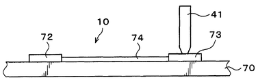
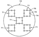
In the heat treatment apparatus which heat-processes a board | substrate to predetermined temperature using a heat treatment mechanism, the temperature of the said heat treatment mechanism is appropriately calibrated by a simple method. The temperature inspection jig 10 of the temperature calibrating apparatus has a to-be-processed wafer 70 mounted on a heat treatment plate and a plurality of Wheatstone bridge circuits 71 provided on the to-be-processed wafer 70. The Wheatstone bridge circuit 71 has four resistance thermometers 72 whose resistance values change with temperature changes, and four contact pads 73 with which the contactors 41 are in contact. In the control unit of the temperature calibrating device, the temperature of the heat treatment plate is adjusted so that the Wheatstone bridge circuit 71 is in an equilibrium state, that is, the offset voltage of the Wheatstone bridge circuit 71 is zero.

Description

TEMPERATURE MEASURING DEVICE, TEMPERATURE CALIBRATING DEVICE AND TEMPERATURE CALIBRATING METHOD}

This invention is equipped with the temperature measuring apparatus for measuring the temperature of the said heat processing mechanism, and the said temperature measuring apparatus with respect to the heat processing apparatus which heat-processes a board | substrate to predetermined temperature using a heat processing mechanism, The said heat processing A temperature calibration apparatus for calibrating the temperature of a device, and a temperature calibration method using the temperature calibration apparatus. In addition, the calibration here means measuring the temperature of a heat processing mechanism, and adjusting the temperature of the said heat processing mechanism to a desired value.

In the photolithography process in the manufacturing process of a semiconductor device, the heat processing (prebaking process) after apply | coating a resist liquid on a semiconductor wafer (henceforth "wafer"), and after exposing a predetermined pattern to a resist film Various heat treatments, such as heat processing (post exposure baking process) and heat processing (post baking process) after developing the exposed resist film, are performed. Moreover, the heat processing which adjusts the temperature of a wafer after these heat processing is also performed. Moreover, also in the plasma processing, such as an etching process and a film-forming process, the heat processing which adjusts the temperature of a wafer is performed.

The above-described heat treatment is performed by loading a wafer on a heat treatment plate set at a predetermined temperature in a heat treatment apparatus, for example. And in order to perform this heat processing suitably, it is important to measure the temperature distribution of the wafer on a heat processing board beforehand, and to appropriately correct the temperature of a heat processing board based on the said measurement result. Therefore, conventionally, the temperature of the wafer in this heat processing is measured.

For the measurement of the temperature of such a wafer, it is proposed to use a wafer type temperature sensor provided with a plurality of temperature sensors and contacts for outputting sensor outputs of the plurality of temperature sensors as output signals. In this case, the contactor provided inside the heat treatment apparatus is brought into contact with the contacts on the wafer. The output signal from the contact point is output to a data management unit provided outside the heat treatment apparatus via the contactor. In the data management unit, the temperature of the wafer is determined based on the output signal (Patent Document 1).

Japanese Patent Application Publication No. 2007-187619

However, on the wafer type temperature sensor of Patent Document 1 described above, since the plurality of temperature sensors are individually connected to the contacts, the resistance values of the respective temperature sensors are all measured. In this case, the number of data managed in the data management unit, that is, the temperature to be measured, becomes very large. Then, when adjusting the temperature of a heat processing board based on the measurement result of these temperatures, control of the said temperature becomes very complicated. Therefore, there was room for improvement in temperature control of the heat treated plate.

Further, even when a wireless measuring device is used, since the resistance values of the plurality of temperature sensors provided on the wafer are all measured in the same manner as in Patent Document 1, temperature control of the heat treatment plate becomes very complicated.

This invention is made | formed in view of such a point, and the heat processing apparatus which heat-processes a board | substrate to predetermined | prescribed temperature using a heat processing mechanism WHEREIN: It aims at properly calibrating the temperature of the said heat processing mechanism by a simple method. It is done.

MEANS TO SOLVE THE PROBLEM In order to achieve the said objective, this invention is a temperature measuring apparatus for measuring the temperature of the said heat processing mechanism with respect to the heat processing apparatus which heat-processes a board | substrate to predetermined temperature using a heat processing mechanism, And a Wheatstone bridge circuit provided on the substrate and provided with a plurality of temperature resistance resistors whose resistance values change with temperature changes.

According to the present invention, the temperature of the heat treatment mechanism can be adjusted such that the Wheatstone bridge circuit formed on the substrate of the temperature measuring device is in equilibrium, that is, the offset voltage in the Wheatstone bridge circuit is zero. In this case, since the offset voltage becomes zero, the resistance values of the plurality of RTDs in the Wheatstone bridge circuit, that is, the temperatures of the substrates measured by the RTDs become equal. Therefore, according to the present invention, the temperature of the heat treatment mechanism can be appropriately adjusted so that the substrate is heat treated uniformly in the horizontal plane. And the thermal processing with respect to the following board | substrate can be performed suitably by the heat processing mechanism adjusted in this way.

In addition, when it is going to measure temperature in several area | regions on a board | substrate, since several temperature resistance resistors are needed, using a conventional method, the temperature of several places according to the number of the said temperature resistance resistors is measured. In doing so, the temperature of the heat treatment mechanism is adjusted using these plurality of parameters. In contrast, according to the present invention, only one parameter used to adjust the temperature of the heat treatment mechanism is the offset voltage of the Wheatstone bridge circuit. Therefore, according to the present invention, the temperature of the heat treatment mechanism can be adjusted by simple control.

The Wheatstone bridge circuit may be provided with a fixed resistor having a predetermined resistance value. In addition, a fixed resistor means that change of a resistance value is small so that change of a resistance value may be negligible with respect to a temperature change.

The present invention according to another aspect is a temperature calibrating device for calibrating the temperature of the heat treatment mechanism with respect to a heat treatment apparatus that heat-treats the substrate at a predetermined temperature using the heat treatment mechanism, the substrate and the substrate on the substrate. And a control unit for controlling the temperature of the heat treatment mechanism such that the Wheatstone bridge circuit includes a plurality of temperature resistance resistors whose resistance is changed in accordance with a temperature change, and the Wheatstone bridge circuit is in equilibrium. It features. The equilibrium state of the Wheatstone bridge circuit means a state in which the potential difference between the midpoints of the Wheatstone bridge circuit becomes zero, that is, the state in which the offset voltage of the Wheatstone bridge circuit becomes zero.

A plurality of Wheatstone bridge circuits may be provided, and the control unit may adjust the temperature of the heat treatment mechanism such that the plurality of Wheatstone bridge circuits are in an equilibrium state.

The controller may adjust the temperature of the heat treatment mechanism so that the current value in the Wheatstone bridge circuit is a predetermined value. In such a case, the resistance value of the RTD in the Wheatstone bridge circuit can be set to a predetermined value. Therefore, the temperature of the heat treatment mechanism can be adjusted to uniformly heat-treat the substrate at a predetermined temperature. Also in this case, since the parameters for adjusting the temperature of the heat treatment mechanism are two of the offset voltage and the current value of the Wheatstone bridge circuit, the temperature of the heat treatment mechanism can be adjusted by simpler control than before.

A plurality of Wheatstone bridge circuits may be provided, and the control unit may adjust the temperature of the heat treatment mechanism so that the current values in the plurality of Wheatstone bridge circuits become equal.

The Wheatstone bridge circuit may be provided with a fixed resistor having a predetermined resistance value.

The said control part may measure the offset voltage of another location in the said Wheatstone bridge circuit, and may adjust the temperature of the said heat processing mechanism so that the said Wheatstone bridge circuit may be in equilibrium in each case.

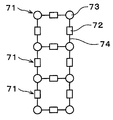
A plurality of Wheatstone bridge circuits may be provided, and the plurality of Wheatstone bridge circuits may be arranged in a zigzag shape, a lattice shape, or in a continuous meandering shape.

The heat treatment mechanism is partitioned into a plurality of regions, and temperature control may be possible for each region.

Moreover, this invention by another viewpoint is the temperature calibration method which corrects the temperature of the said heat processing apparatus using a temperature correction apparatus with respect to the heat processing apparatus which heat-processes a board | substrate to predetermined temperature using a heat processing mechanism, The Wheatstone bridge circuit is in an equilibrium state using the temperature calibrating device comprising a substrate and a Wheatstone bridge circuit provided on the substrate and having a plurality of temperature resistance resistors whose resistance values change with temperature changes. The temperature of the heat treatment mechanism is adjusted as possible.

A plurality of Wheatstone bridge circuits may be provided, and the temperature of the heat treatment mechanism may be adjusted such that the plurality of Wheatstone bridge circuits are in an equilibrium state.

The temperature of the heat treatment mechanism may be adjusted such that the current value in the Wheatstone bridge circuit is a predetermined value.

A plurality of Wheatstone bridge circuits may be provided, and the temperature of the heat treatment mechanism may be adjusted so that the current values in the plurality of Wheatstone bridge circuits become equal.

The Wheatstone bridge circuit may be provided with a fixed resistor having a predetermined resistance value.

In the Wheatstone bridge circuit, offset voltages at other points may be measured, and in each case, the temperature of the heat treatment mechanism may be adjusted so that the Wheatstone bridge circuit is in an equilibrium state.

The heat treatment mechanism may be divided into a plurality of regions, and the temperature of the heat treatment mechanism may be adjusted for each of the regions.

According to the present invention, in the heat treatment apparatus for heat-treating a substrate at a predetermined temperature using a heat treatment mechanism, the temperature of the heat treatment mechanism can be appropriately corrected by a simple method.

BRIEF DESCRIPTION OF THE DRAWINGS Explanatory drawing which shows the outline of the structure of the temperature correction apparatus and heat processing apparatus which concern on this embodiment.
2 is a plan view illustrating an outline of a configuration of a heat treatment plate.
3 is a plan view illustrating an outline of a configuration of a temperature inspection jig;
4 is an explanatory diagram showing an outline of the configuration of a Wheatstone bridge circuit;
5 is a side view illustrating an outline of a configuration of a temperature test jig.
6 is a plan view illustrating an outline of a configuration of a temperature test jig according to another embodiment.
7 is an explanatory diagram showing an arrangement of a Wheatstone bridge circuit according to another embodiment.
8 is a plan view illustrating an outline of a configuration of a temperature test jig according to another embodiment.
9 is a plan view illustrating an outline of a configuration of a temperature test jig according to another embodiment.
10 is a plan view illustrating an outline of a configuration of a temperature test jig according to another embodiment.
11 is a plan view illustrating an outline of a configuration of a temperature inspection jig according to another embodiment.

EMBODIMENT OF THE INVENTION Hereinafter, embodiment of this invention is described. FIG. 1: is explanatory drawing which shows the outline of the structure of the temperature correction apparatus 1 which concerns on this embodiment, and the heat processing apparatus 2 to which the said temperature correction apparatus 1 is applied. The temperature calibrating apparatus 1 adjusts the temperature of the heat processing board 50 as a heat processing mechanism mentioned later with respect to the heat processing apparatus 2, and the temperature test jig 10 mounted in the said heat processing board 50 is carried out. ) Moreover, the heat processing apparatus 2 loads the wafer W as a board | substrate on the heat processing board 50, and performs the heat processing of the said wafer W. As shown in FIG.

The heat processing apparatus 2 has the processing container 20 in which the temperature inspection jig 10 or the carrying-in / out port (not shown) of the wafer W was formed in the side surface as shown in FIG. In the processing container 20, the cover member 30 which is located in the upper side and can move up and down in the vertical direction, and the hot plate accommodating part 31 which is located below and is integral with the cover member 30 to form the process chamber K ) Is installed.

The lid member 30 has a substantially cylindrical shape. The projection 40 is formed in the outer peripheral part of the lower surface of the cover member 30, and the said projection part 40 comes into contact with the hot plate accommodating part 31, and the process chamber K is formed. In addition, a plurality of contacts 41 such as pogo pins, for example, extending in the vertical direction, are provided on the lower surface of the lid member 30. As the contact 41, a conductive material is used. The some contact 41 is arrange | positioned correspondingly (counter) to the contact pad 73 mentioned later of the temperature test jig 10. Moreover, the exhaust part 42 is provided in the upper surface center part of the cover member 30. The atmosphere in the processing chamber K is uniformly exhausted from the exhaust section 42.

The hot plate accommodating part 31 accommodates the heat processing board 50, and has the annular holding member 51 which hold | maintains the outer peripheral part of the heat processing board 50, and the outer periphery of the holding member 51. A substantially cylindrical support ring 52 is provided.

As shown in FIG. 2, the heat treatment plate 50 is divided into a plurality of, for example, four hot plate regions R 1 , R 2 , R 3 , and R 4 . The heat treatment board 50 is divided into quarters, for example, in plan view. That is, the hot plate regions R 1 , R 2 , R 3 , and R 4 each have a fan shape with a central angle of 90 degrees.

In each hot plate region R 1 to R 4 of the heat treatment plate 50, a heater 53 that generates heat by electric supply is separately installed and can be heated for each hot plate region R 1 to R 4 . . The amount of heat generated by the heater 53 in each of the hot plate regions R 1 to R 4 is controlled by the controller 100 described later. The controller 100 may control the amount of heat generated by the heater 53 to control the temperature of each of the hot plate regions R 1 to R 4 to a predetermined temperature.

As shown in FIG. 1, a lifting pin 60 is provided below the heat treatment plate 50 to support and lift the temperature inspection jig 10 or the wafer W from below. The lifting pin 60 can move up and down in the vertical direction by the lifting drive mechanism 61. In the vicinity of the central portion of the heat treatment plate 50, a through hole 62 penetrating the heat treatment plate 50 in the thickness direction is formed. The lifting pin 60 rises from below the heat treatment plate 50, passes through the through hole 62, and can protrude upward from the heat treatment plate 50.

Next, the structure of the temperature correction apparatus 1 is demonstrated. The temperature calibrating apparatus 1 has the temperature test jig 10 mounted on the heat processing board 50 as shown in FIG. The temperature inspection jig 10 has the to-be-processed wafer 70 as a board | substrate as shown in FIG. The target wafer 70 is made of the same material as the wafer W, for example, silicon, and has the same planar shape as the wafer W. FIG. In addition, in order to measure accurate temperature, it is preferable that the to-be-processed wafer 70 is the same as the actual wafer W, but it is not limited to this, It does not matter even if a shape, a material, etc. differ. For example, a high heat radiation board for LEDs may be used. Since the substrate is made of a metal such as Al or Cu as the base substrate, the heat resistance is also high, and the warpage of the processing target wafer 70 does not become a problem even in a high temperature environment due to high thermal conductivity.

On the wafer 70 to be processed, a plurality of Wheatstone bridge circuits 71 are formed. In this embodiment, the plurality of Wheatstone bridge circuits 71 are arranged in a zigzag shape over substantially the entire surface of the wafer to be processed 70. Each Wheatstone bridge circuit 71 has a configuration in which four RTDs 72 and four contact pads 73 are electrically connected by a wiring 74 as shown in FIGS. 3 and 4. . In addition, these RTD 72, the contact pad 73, and the wiring 74 are collectively formed by performing the photolithographic process to the to-be-processed wafer 70, for example. In addition, when the to-be-processed wafer 70 is a conductor, what is necessary is just to perform sufficient insulation processing on the surface before these elements are formed.

The resistance thermometer 72 is a resistor whose resistance value changes with temperature change, for example, a resistance temperature detector (RTD), a thermistor, or the like is used. The resistance thermometer 72 is disposed at a measurement point of the temperature of the wafer 70 to be processed.

As shown in FIG. 5, a contactor 41 is brought into contact with the contact pad 73 when the temperature of the heat treatment plate 50 is adjusted. As the contact pad 73, a conductive material, for example, aluminum is used. As shown in FIG. 4, four contact pads 73 are arranged at the apex of the Wheatstone bridge circuit 71. The pair of contact pads 73a and 73a provided at both ends of the two resistance thermometers 72 and 72 in series are used to apply a voltage to the Wheatstone bridge circuit 71. In addition, a pair of contact pads 73b and 73b provided at the midpoints of the two resistance thermometers 72 and 72 in series are used to measure the voltage between the contact pads 73b and 73b. That is, the contact pads 73b and 73b are used to measure the offset voltage in the Wheatstone bridge circuit 71. In addition, the arrow in FIG. 4 has shown the electric current when the voltage is applied to the Wheatstone bridge circuit 71. As shown in FIG.

In addition, for example, aluminum is used for the wiring 74 similarly to the contact pad 73.

In addition, the temperature calibrating apparatus 1 has the control part 100 provided in the exterior of the heat processing apparatus 2, as shown in FIG. The control part 100 is a computer, for example, and has the measurement circuit provided with a processor, a memory, an amplifier, a switch, etc., for example. By this measuring circuit, the control part 100 can measure the offset voltage etc. in the Wheatstone bridge circuit 71. FIG. In addition, the control part 100 has a program storage part (not shown). The program storage unit stores, for example, a program for adjusting the temperature (heat value of the heater 53) of the heat treatment plate 50 based on the offset voltage in the Wheatstone bridge circuit 71. The program is recorded in a computer-readable storage medium such as a computer readable hard disk (HD), a flexible disk (FD), a compact disk (CD), a magneto optical disk (MO), a memory card, and the like. It may exist, and it may be installed in the control part 100 from the storage medium. In addition, when the heat processing apparatus 2 itself has the temperature control mechanism which adjusts the temperature of the heat processing board 50, the control part 100 controls the said temperature control mechanism based on the measured temperature. You may do it. What is necessary is just to respond suitably according to the function which the heat processing apparatus 2 has.

Next, the method of adjusting the temperature of the heat processing board 50 of the heat processing apparatus 2 using the temperature calibration device 1 comprised as mentioned above is demonstrated.

First, the temperature test jig 10 is carried in to the heat processing apparatus 2. The temperature test jig 10 is transmitted to the lifting pins 60 that have risen and waited in advance. Thereafter, the lifting pins 60 are lowered, and the temperature inspection jig 10 is mounted on the heat treatment plate 50. At this time, each of the hot plate regions R 1 to R 4 of the heat treatment plate 50 is adjusted to a predetermined initial temperature by the control unit 100. Thereafter, the lid member 30 is lowered to a predetermined position, and the lid member 30 is closed. Then, heat treatment is performed on the target wafer 70 of the temperature inspection jig 10 loaded on the heat treatment plate 50 for a predetermined time.

On the other hand, the contactor 41 is in contact with the contact pad 73 of the temperature inspection jig 10 mounted on the heat treatment plate 50. Then, when the heat treatment to the target wafer 70 is completed, a predetermined voltage is applied to the contact pads 73a and 73a on the target wafer 70 through the contactor 41. Subsequently, the signal of the measurement result is output from the contact pads 73b and 73b to the control part 100 via the contactor 41. In this way, the control part 100 measures the offset voltage (voltage between contact pads 73b and 73b) of the Wheatstone bridge circuit 71. And the control part 100 adjusts the temperature of the heat processing board 50 so that the offset voltage of some wheatstone bridge circuit 71 may become zero. That is, the control section 100, the offset voltage of the plurality of the Wheatstone bridge circuit 71 becomes zero, and control the temperature of the heat treatment board 50, each hot plate region (R 1 to R 4).

Note that the offset voltage of the Wheatstone bridge circuit 71 becomes zero means that the resistance values of the four RTDs 72 in the Wheatstone bridge circuit 71 become equal. That is, the temperature of the to-be-processed wafer 70 provided with the Wheatstone bridge circuit 71 becomes uniform. Therefore, when the offset voltages of all the Wheatstone bridge circuits 71 become zero, the temperature of the entire processing target wafer 70 becomes uniform.

When the temperature of the heat processing board 50 is adjusted as mentioned above, the lifting pin 60 is raised and the temperature test jig 10 is taken out from the heat processing apparatus 2. In this way, the temperature of the heat processing board 50 is adjusted.

In addition, when the offset voltage of all the Wheatstone bridge circuits 71 cannot be zero by one temperature adjustment, a plurality of temperature adjustments are performed. That is, the heat treatment of the wafer 70 to be processed, the measurement of the offset voltage of the Wheatstone bridge circuit 71, and the temperature adjustment of the heat treatment plate 50 are repeatedly performed, so that the offset voltages of all the Wheatstone bridge circuits 71 are adjusted. To zero.

According to the above embodiment, the heat treatment board so that the Wheatstone bridge circuit 71 formed on the processing target wafer 70 is in equilibrium, that is, the offset voltage in the Wheatstone bridge circuit 71 becomes zero. The temperature of 50 is adjusted. In this case, since the offset voltage becomes zero, the resistance values of the four RTDs 72 in the Wheatstone bridge circuit 71, that is, the temperature of the wafer 70 to be measured by these RTDs 72. Becomes equivalent. In addition, since the offset voltages of all Wheatstone bridge circuits 71 on the target wafer 70 become zero, the temperatures of the target wafers 70 in the Wheatstone bridge circuit 71 become equal. . Therefore, according to this embodiment, the temperature of the heat processing board 50 can be adjusted suitably so that the to-be-processed wafer 70 may be heat-processed uniformly in a horizontal plane. In other words, this embodiment should just ensure the in-plane uniformity of the temperature of the to-be-processed wafer 70 at the time of the temperature control of the heat processing board 50, and is especially useful when absolute temperature control is unnecessary. Although the setting output of the heat processing board 50 is reliable by nature, it is common in the actual field that the object which an output value changes with time passes. In such a case, it can be regarded that temperature control is sufficiently performed at the time point where in-plane uniformity is secured.

In addition, since the Wheatstone bridge circuit 71 is provided with four resistance thermometers 72, when using the conventional method, four temperature is measured. In doing so, the temperature of the heat treatment plate 50 is adjusted using these four parameters. In contrast, according to the present embodiment, only one parameter used for adjusting the temperature of the heat treatment plate 50 is one of the offset voltage of the Wheatstone bridge circuit 71. Thus, according to this embodiment, since there are few parameters, the temperature of the heat processing board 50 can be adjusted by simple control. Therefore, the load on the heater 53 of the heat processing board 50 can be made small, and temperature control of the heat processing board 50 can be performed in a short time.

Here, when measuring the resistance value of a resistance thermometer, when using the 2-wire connection type or 4-wire connection type normally used, two or four contact pads (two or four wiring) with respect to one resistance thermometer Is installed. In contrast, in the Wheatstone bridge circuit 71 of the present embodiment, four contact pads 73 (four wires 74) are provided for the four RTDs 72. Therefore, according to this embodiment, the number of contact pads 73 and the number of wirings 74 can be reduced.

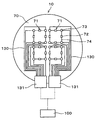
In addition, a built-in heat treatment board 50 is partitioned into a plurality of heat plate area (R 1 to R 4), each hot plate region (R 1 to R 4) in the individual heaters 53 to the. Because of this, it is possible to control the temperature of each hot plate region (R 1 to R 4), it can be more precisely perform the temperature control of the thermal processing plate 50.

In the above-mentioned embodiment, although the offset voltage in the Wheatstone bridge circuit 71 was used as a parameter which controls the temperature of the heat processing board 50, in addition to this offset voltage, in the Wheatstone bridge circuit 71, The current value of may be used.

In this case, in the heat treatment apparatus 2, after heat-processing the temperature test jig 10 mounted on the heat processing board 50, the Wheatstone bridge circuit in the said temperature test jig 10 ( In addition to the offset voltage of 71, the current value of the Wheatstone bridge circuit 71 is measured. In the controller 100, the offset voltages of all the Wheatstone bridge circuits 71 become zero, the current value of the Wheatstone bridge 71 becomes a predetermined value, and all the Wheatstone bridge circuits 71 The temperature of the heat processing board 50 is adjusted so that the electric current value may become equal.

According to this embodiment, the resistance value of the RTD 72 in all the Wheatstone bridge circuits 71 on the to-be-processed wafer 70 can be made into the predetermined value equally. Therefore, the temperature of the heat processing board 50 can be adjusted to uniformly heat-process the to-be-processed wafer 70 to predetermined temperature. Even in such a case, since the parameters for adjusting the temperature of the heat treatment plate 50 are two of the offset voltage and the current value of the Wheatstone bridge circuit 71, the heat treatment plate 50 can be controlled by simpler control than before. The temperature can be adjusted.

In the above embodiment, the control unit 100 records, for example, a table (not shown) indicating the relationship between the current value in the Wheatstone bridge circuit 71 and the temperature of the wafer 70 to be processed. You may be. In this case, the control part 100 measures the temperature of the to-be-processed wafer 70 using the said table based on the measured electric current value of the Wheatstone bridge circuit 71. Thereby, the absolute temperature of the to-be-processed wafer 70 after heat processing can be grasped.

In addition, in the Wheatstone bridge circuit 71, one of the four RTDs 72 may be replaced with a fixed resistor having a predetermined resistance value. The fixed resistor means that the change in the resistance value is small so that the change in the resistance value is negligible with respect to the temperature change. For example, a Wheatstone bridge circuit 71 composed of one fixed resistor having 1385Ω and three Pt1000 (temperature resistance resistor 72) is prepared. It can be seen that Pt1000 has a resistance value of 1385 Ω at 100 ° C. In this case, only the offset voltage of the Wheatstone bridge circuit 71 is controlled to be zero, and the remaining three RTDs 72 become 1385?. That is, these three resistance thermometers 72 are controlled by 100 degreeC. Although the temperature of the location where the fixed resistor is disposed cannot be measured, absolute temperature control is also possible without measuring the current value. Therefore, this method is very effective when the temperature at which the heat treatment plate 50 is to be controlled is predetermined. In addition, the number which can be substituted by a fixed resistor is not limited to one, Two or more may be sufficient as it.

In the above embodiment, since the offset voltage of the Wheatstone bridge circuit 71 becomes zero, it is assumed that the resistances of the four RTDs 72 are equal. In practice, however, if the two left-side RTDs 72 of the Wheatstone bridge circuit 71 have the same resistance values, and the two right-side RTDs 72 have the same resistance values, Even if the resistance value varies depending on the resistance thermometer 72, the offset voltage becomes zero. For example, two cases on the left side are 1000 Ω, and two cases on the right side are 980 Ω. In such a case, although the temperature differs depending on the left and right sides of the Wheatstone bridge circuit 71, there is a possibility that all four are recognized as the same temperature. As a method of avoiding the occurrence of such a situation, it is effective to change the measurement position of the offset voltage of the Wheatstone bridge circuit 71. First, measurement of the offset voltage and control are performed so that the offset voltage becomes zero. Control so far is as described in the above embodiment. Here, the second offset voltage is measured while the contactor 41 is in contact with the contact pads 73a, 73a, 73b, and 73b on the target wafer 70. The voltage was applied between the contact pads 73a and 73a so far, but this time the voltage is applied between the contact pads 73b and 73b. Subsequently, the offset voltage (voltage between the contact pads 73a and 73a) of the Wheatstone bridge circuit 71 is measured from the contact pads 73a and 73a through the contactor 41. If the second offset voltage (voltage between the contact pads 73a and 73a) is also zero, in the Wheatstone bridge circuit 71, the four RTDs 72 are all at the same temperature. In addition, the measurement of the second offset voltage is set at an arbitrary timing. It may be performed immediately after measuring the first offset voltage, or after the offset voltage is set to zero, the second offset voltage may be measured to confirm.

In the above embodiment, the plurality of Wheatstone bridge circuits 71 are arranged in a zigzag shape on the processing target wafer 70, but the arrangement of the plurality of Wheatstone bridge circuits 71 is not limited thereto. For example, as shown in FIG. 6, the plurality of Wheatstone bridge circuits 71 may be arranged in a lattice shape on the wafer to be processed. For example, as shown in FIG. 7, the plurality of Wheatstone bridge circuits 71 are continuously arranged, and as shown in FIG. 8, the plurality of Wheatstone bridges are provided on the wafer 70 to be processed. The circuit 71 may be disposed meandering. In all cases, based on the offset voltage of the Wheatstone bridge circuit 71 or the offset voltage and the current value, the temperature of the heat treatment plate 50 can be adjusted to uniformly heat-process the wafer 70 to be processed. have.

In addition, although the some contact pad 73 of the above embodiment was arrange | positioned in the peak part in the Wheatstone bridge circuit 71, as shown, for example in FIG. 9, the some contact pad 73 is, It may be arranged continuously along the periphery of the wafer to be processed 70. In this case, the metal pad 110 connected to the two wirings 74 is disposed at the peak portion in the Wheatstone bridge circuit 71. Each metal pad 110 and each contact pad 73 are connected by a wiring 111. As the metal pad 110 and the wiring 111, a conductive material, for example, aluminum is used. In addition, in this embodiment, since the contactor 41 does not contact the metal pad 110, the said metal pad 110 may be abbreviate | omitted and the wiring 74 and the wiring 111 may be directly connected.

Here, when the temperature inspection jig 10 is carried in the heat processing apparatus 2, the to-be-processed wafer 70 is mounted on the heat processing board 50, for example in the state rotated in the horizontal plane from a predetermined position. It may become. Also in this case, since the contact pads 73 are continuously arranged along the periphery of the wafer to be processed 70, the contact 41 can be reliably brought into contact with the contact pads 73. For this reason, the offset voltage and the electric current value of the Wheatstone bridge circuit 71 can be measured reliably, and the temperature of the heat processing board 50 can be adjusted suitably.

Moreover, since the contact pad 73 is arrange | positioned at the periphery of the to-be-processed wafer 70 spaced apart from the temperature resistance resistor 72, when the contact 41 contacts the said contact pad 73, the said contact 41 is carried out. The resistance thermometer 72 is not affected by the temperature change by the contact of. Therefore, the offset voltage and the current value of the Wheatstone bridge circuit 71 can be measured more reliably.

In the above embodiment, as shown in FIG. 10, one Wheatstone bridge circuit among the plurality of Wheatstone bridge circuits 71 may be the reference Wheatstone bridge circuit 120. The reference Wheatstone bridge circuit 120 has four reference resistors 121 instead of four temperature resistance resistors 72. The reference resistor 121 has a resistance value which does not change with temperature change, and has a resistance value which is dissociated with the resistance value of the RTD 72 by a predetermined amount or more, for example, 300? Or more. In addition, the reference wheatstone bridge circuit 120 has four reference contact pads 122 instead of four contact pads 73. The plurality of contact pads 73 and the reference contact pads 122 are continuously disposed along the periphery of the target wafer 70. In addition, since the other structure of the reference wheatstone bridge circuit 120 is the same as that of the wheatstone bridge circuit 71 in the said embodiment, description is abbreviate | omitted.

As described above, since the resistance value does not change with temperature change and the resistance value of the temperature resistance resistor 72 is dissociated by a predetermined amount or more, the reference resistor 121 opens the target wafer 70. The resistance value of the resistance thermometer 72 and the resistance value of the reference resistor 121 can be distinguished. Thereby, since the control part 100 can grasp | ascertain the position of the reference resistor 121 with respect to the heat processing board 50, it can grasp the position of the other RTD 72, and is on the heat processing board 50 The position in the horizontal surface of the to-be-processed wafer 70 can also be grasped. That is, the positions of the reference resistor 121 and the RTD 72 and the hot plate regions R 1 to R 4 of the heat treatment plate 50 can correspond to each other. Thus, according to this embodiment, the temperature control of the thermal processing plate 50 can be appropriately performed for each hot plate region (R 1 to R 4).

In the above embodiment, the contactor 41 is brought into contact with the contact pad 73 of the temperature test jig 10 when the offset voltage and the current value of the wheatstone bridge circuit 71 are measured. It is applicable to various temperature inspection jig 10 having the circuit 71.

For example, as shown in FIG. 11, you may use the streamlined temperature inspection jig 10. The contact pads 73 of the temperature inspection jig 10 are connected to the flexible cable 131 through the wiring 130. In addition, the flexible cable 131 is connected to the control part 100. In this embodiment, when measuring the offset voltage and the current value of the Wheatstone bridge circuit 71, it is not necessary to bring the contact 41 into contact with the contact pad 73. For this reason, the contact pad 73 may be abbreviate | omitted and the wiring 74 and the wiring 111 may be directly connected. In addition, the contact 41 provided in the lower surface of the lid member 30 may also be omitted.

In this case, the temperature test jig 10 is disposed inside the heat treatment apparatus 2, and the control unit 100 is disposed outside the heat treatment apparatus 2. Then, heat treatment is performed on the wafer 70 to be processed in this state, and the offset voltage and current value of the Wheatstone bridge circuit 71 are measured.

In addition, in the streamlined temperature test jig 10 of this embodiment, although the measurement circuit was provided in the control part 10, you may provide this measurement circuit on the to-be-processed wafer 70. FIG.

In addition, you may use a wireless temperature test jig for the temperature test jig 10. In this case, a measurement circuit (not shown) provided in the control unit 100 is provided on the processing target wafer 70. The offset voltage and current value of the Wheatstone bridge circuit 71 are wirelessly output from the measurement circuit to the controller 100.

Even when any of the wired or wireless temperature test jig 10 is used as described above, the wafer to be processed 70 is based on the offset voltage or the offset voltage and current value of the Wheatstone bridge circuit 71. The temperature of the heat treatment plate 50 can be adjusted so as to uniformly heat treat.

In the above embodiment, the heat treatment plate 50 is partitioned into four hot plate regions R 1 to R 4 , but the number can be arbitrarily selected. In addition, the shape of the hot plate regions R 1 to R 4 of the heat treatment plate 50 can also be arbitrarily selected.

In addition, the heat treatment performed in the heat treatment apparatus 2 of the above embodiment may be, for example, a heat treatment in a photolithography treatment, or a heat treatment in a plasma treatment such as an etching treatment or a film formation treatment. . In this case, the heat which moves to the wafer W is not limited to the heat from the heat processing board 50, but also contains the heat transfer from an etching gas or a plasma.

As mentioned above, although preferred embodiment of this invention was described referring an accompanying drawing, this invention is not limited to this example. It is apparent to those skilled in the art that various modifications or modifications can be conceived within the scope of the spirit described in the claims, and those of course belong to the technical scope of the present invention. The present invention is not limited to this example, and various forms can be employed. The present invention is also applicable to the case where the substrate is other substrates such as FPDs (flat panel displays) other than wafers and mask reticles for photomasks.

1: temperature calibration device
2: heat treatment device
10: temperature inspection jig
30: cover member
41: contactor
50: heat treatment plate
70 wafer to be processed
71: Wheatstone bridge circuit
72: resistance thermometer
73: contact pad
100:
120: reference Wheatstone bridge circuit
121: reference resistor
122: reference contact pad
131: Flexible Cable
R1 to R4: hot plate region
W: Wafer

Claims (17)

It is a temperature measuring apparatus for measuring the temperature of the said heat processing mechanism with respect to the heat processing apparatus which heat-processes a board | substrate to predetermined temperature using a heat processing mechanism,
A substrate;
And a Wheatstone bridge circuit provided on the substrate and provided with a plurality of temperature resistance resistors whose resistance value is changed in accordance with a temperature change.
The temperature measurement device according to claim 1, wherein the Wheatstone bridge circuit includes a fixed resistor having a predetermined resistance value. It is a temperature calibration apparatus for calibrating the temperature of the said heat processing mechanism with respect to the heat processing apparatus which heat-processes a board | substrate to predetermined temperature using a heat processing mechanism,
A substrate;
A Wheatstone bridge circuit provided on the substrate, the Wheatstone bridge circuit including a plurality of resistance thermometers whose resistance value changes with temperature change;
And a control unit for adjusting the temperature of the heat treatment mechanism such that the Wheatstone bridge circuit is in an equilibrium state.
4. The Wheatstone bridge circuit according to claim 3, wherein a plurality of Wheatstone bridge circuits are provided,
And the control unit adjusts a temperature of the heat treatment mechanism so that a plurality of the Wheatstone bridge circuits are in an equilibrium state.
The temperature adjusting device according to claim 3 or 4, wherein the control unit adjusts a temperature of the heat treatment mechanism so that a current value in the Wheatstone bridge circuit becomes a predetermined value. The said Wheatstone bridge circuit is provided in multiple numbers,
The said control part adjusts the temperature of the said heat processing mechanism so that the electric current value in several said Wheatstone bridge circuit may become equal, The temperature correction apparatus characterized by the above-mentioned.
The temperature correction device according to claim 3 or 4, wherein the Wheatstone bridge circuit includes a fixed resistor having a predetermined resistance value. The said heat processing mechanism of Claim 3 or 4 WHEREIN: The said control part measures the offset voltage of the other place in the said Wheatstone bridge circuit, and in each case, the said heat processing mechanism so that the said Wheatstone bridge circuit may be in an equilibrium state. The temperature calibration device, characterized in that for controlling the temperature of. The said Wheatstone bridge circuit is provided in multiple numbers,
The plurality of Wheatstone bridge circuits are arranged in a zigzag shape, a lattice shape, or continuously meandering.
The temperature correcting apparatus according to claim 3 or 4, wherein the heat treatment mechanism is divided into a plurality of regions, and the temperature can be adjusted for each region. It is a temperature calibration method of calibrating the temperature of the said heat processing apparatus using a temperature calibration apparatus with respect to the heat processing apparatus which heat-processes a board | substrate to predetermined temperature using a heat processing mechanism,
A substrate;
Using the temperature calibration apparatus provided on the said board | substrate and comprised with the Wheatstone bridge circuit provided with the some temperature resistance resistor whose resistance value changes with a temperature change,
And adjusting the temperature of the heat treatment mechanism such that the Wheatstone bridge circuit is in an equilibrium state.
12. The plurality of Wheatstone bridge circuits are provided.
And adjusting the temperature of said heat treatment mechanism such that a plurality of said Wheatstone bridge circuits are in an equilibrium state.
13. The method according to claim 11 or 12,
And a temperature of the heat treatment mechanism is adjusted so that the current value in the Wheatstone bridge circuit is a predetermined value.
The plurality of Wheatstone bridge circuits are provided.
The temperature correction method is characterized in that the temperature of the heat treatment mechanism is adjusted so that the current values in the plurality of Wheatstone bridge circuits become equal.
The temperature correction method according to claim 11 or 12, wherein the Wheatstone bridge circuit includes a fixed resistor having a predetermined resistance value. 13. The temperature of the heat treatment mechanism according to claim 11 or 12, wherein the offset voltage at different points is measured in the Wheatstone bridge circuit, and the temperature of the heat treatment mechanism is adjusted so that the Wheatstone bridge circuit is in equilibrium in each case. Temperature calibration method characterized in that. The said heat treatment mechanism is divided into several area | regions,
And adjusting the temperature of the heat treatment mechanism for each of the regions.
KR1020120043711A 2011-04-27 2012-04-26 Temperature measuring device, temperature calibrating device and temperature calibrating method KR20120121852A (en)

Priority Applications (1)

Application Number Priority Date Filing Date Title
KR1020120043711A KR20120121852A (en) 2011-04-27 2012-04-26 Temperature measuring device, temperature calibrating device and temperature calibrating method

Applications Claiming Priority (2)

Application Number Priority Date Filing Date Title
JPJP-P-2011-098991 2011-04-27
KR1020120043711A KR20120121852A (en) 2011-04-27 2012-04-26 Temperature measuring device, temperature calibrating device and temperature calibrating method

Publications (1)

Publication Number Publication Date
KR20120121852A true KR20120121852A (en) 2012-11-06

Family

ID=47508247

Family Applications (1)

Application Number Title Priority Date Filing Date
KR1020120043711A KR20120121852A (en) 2011-04-27 2012-04-26 Temperature measuring device, temperature calibrating device and temperature calibrating method

Country Status (1)

Country Link
KR (1) KR20120121852A (en)

Cited By (2)

* Cited by examiner, † Cited by third party
Publication number Priority date Publication date Assignee Title
KR20180001475A (en) * 2016-06-24 2018-01-04 도쿄엘렉트론가부시키가이샤 Substrate processing system and temperature control method
US20210068718A1 (en) * 2015-11-17 2021-03-11 University-Industry Cooperation Group Of Kyung Hee University Device for measuring biological information including sensor array and method of measuring biological information using device

Cited By (4)

* Cited by examiner, † Cited by third party
Publication number Priority date Publication date Assignee Title
US20210068718A1 (en) * 2015-11-17 2021-03-11 University-Industry Cooperation Group Of Kyung Hee University Device for measuring biological information including sensor array and method of measuring biological information using device
US11911153B2 (en) * 2015-11-17 2024-02-27 University-Industry Cooperation Group Of Kyung Hee University Device for measuring biological information including sensor array and method of measuring biological information using device
KR20180001475A (en) * 2016-06-24 2018-01-04 도쿄엘렉트론가부시키가이샤 Substrate processing system and temperature control method
KR20220010567A (en) * 2016-06-24 2022-01-25 도쿄엘렉트론가부시키가이샤 Substrate processing system and temperature control method

Similar Documents

Publication Publication Date Title
US20120275484A1 (en) Temperature measuring device, temperature calibrating device and temperature calibrating method
US7831135B2 (en) Method and system for controlling bake plate temperature in a semiconductor processing chamber
JP5485936B2 (en) Temperature calibration apparatus and temperature calibration method
US6229116B1 (en) Heat treatment apparatus
JP4444090B2 (en) Heat treatment plate temperature setting method, heat treatment plate temperature setting device, program, and computer-readable recording medium recording the program
JP4509820B2 (en) Heat treatment plate temperature setting method, heat treatment plate temperature setting device, program, and computer-readable recording medium recording the program
JP4904822B2 (en) Equipment with temperature measurement function
TWI643246B (en) Heat treatment device, abnormality detection method in heat treatment, and readable computer memory medium
US7957828B2 (en) Temperature setting method for thermal processing plate, temperature setting apparatus for thermal processing plate, and computer-readable storage medium
US20080224817A1 (en) Interlaced rtd sensor for zone/average temperature sensing
JP6481636B2 (en) Hot plate temperature measuring device and hot plate temperature measuring method
US7275865B2 (en) Temperature measuring apparatus using change of magnetic field
JP2012231040A (en) Temperature calibration apparatus and temperature calibration method
JP2007019094A (en) Semiconductor testing device
JPH09189613A (en) Temperature measuring device, processing device and processing method
KR20120121852A (en) Temperature measuring device, temperature calibrating device and temperature calibrating method
JP2006222354A (en) Method for setting temperature of heat treatment plate, equipment for setting temperature of heat treatment, program, and program-recorded computer-readable recording medium
JP2009164483A (en) Method of manufacturing semiconductor device, and semiconductor substrate processing device
JP2008141071A (en) Apparatus for heat-treating substrate
JP5266452B2 (en) Temperature characteristic measuring device
JP4043408B2 (en) Substrate processing apparatus and substrate processing method
US8135487B2 (en) Temperature setting method and apparatus for a thermal processing plate
JP3571634B2 (en) Substrate processing equipment
JP3977275B2 (en) Heat treatment equipment
KR100503515B1 (en) Apparatus of temperature calibration and method of temperature calibration using the same

Legal Events

Date Code Title Description
A201 Request for examination
E902 Notification of reason for refusal
E601 Decision to refuse application