KR20120121069A - Heater Apparatus For Heating Plating Tank - Google Patents
Heater Apparatus For Heating Plating Tank Download PDFInfo
- Publication number
- KR20120121069A KR20120121069A KR1020110038816A KR20110038816A KR20120121069A KR 20120121069 A KR20120121069 A KR 20120121069A KR 1020110038816 A KR1020110038816 A KR 1020110038816A KR 20110038816 A KR20110038816 A KR 20110038816A KR 20120121069 A KR20120121069 A KR 20120121069A
- Authority
- KR
- South Korea
- Prior art keywords
- heating
- plating
- fixing
- heating unit
- plating bath
- Prior art date
Links
Images


Classifications
-
- C—CHEMISTRY; METALLURGY
- C25—ELECTROLYTIC OR ELECTROPHORETIC PROCESSES; APPARATUS THEREFOR
- C25D—PROCESSES FOR THE ELECTROLYTIC OR ELECTROPHORETIC PRODUCTION OF COATINGS; ELECTROFORMING; APPARATUS THEREFOR
- C25D21/00—Processes for servicing or operating cells for electrolytic coating
- C25D21/02—Heating or cooling
Landscapes
- Chemical & Material Sciences (AREA)
- Engineering & Computer Science (AREA)
- Chemical Kinetics & Catalysis (AREA)
- Electrochemistry (AREA)
- Materials Engineering (AREA)
- Metallurgy (AREA)
- Organic Chemistry (AREA)
- Electroplating Methods And Accessories (AREA)
Abstract
The present invention relates to a heating apparatus for a plating bath, comprising a heating unit for converting electrical energy supplied from the outside into heat energy to generate heat, and a fixing unit for fixing the heating unit in a plurality of circles to thereby fix the shape, and thus the surface area of the heating unit. By extending the lowering of the heating time and heating temperature of the heater device for heating the plating liquid there is an effect that can prevent the damage to the heater device.
Description
The present invention relates to a plating apparatus heater apparatus, and more particularly, to a plating apparatus heater apparatus capable of rapidly heating the plating liquid contained in the plating vessel.
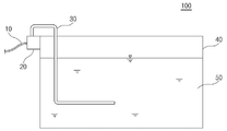
Conventionally, the plating heater apparatus used to plate the surface of a non-ferrous ferrous metal or non-metallic material is generally adopted as shown in Figure 1, the heating portion is generally employed as shown in FIG.
1 and 2, the plating
The
The
The
The
More specifically, the
In order to plate the object to be plated with the
In addition, since the
In addition, since the
As a result, when the components constituting the
Accordingly, it is an object of the present invention to provide a plating apparatus heater device which prevents damage to the heater apparatus by extending the surface area of the heater apparatus and lowering the heating time and heating temperature of the heater apparatus for heating the plating liquid.
In addition, an object of the present invention is to provide a heater device capable of preventing the occurrence of fire by reducing the heat transferred to the plating bath even when the plating solution is evaporated by the heating of the heater device and the heater device is exposed to the outside.
Another object of the present invention is to provide a heating apparatus for a plating bath which prolongs the life of the heating apparatus and the plating liquid by preventing damage to the heater apparatus.
In order to achieve the above object, the plating apparatus heater apparatus according to the present invention includes a heating unit for generating heat by converting the electrical energy supplied from the outside into thermal energy, the fixing unit for fixing the shape by winding the heating unit in a plurality of circles form Characterized in that.
In addition, the surface of the heating portion, characterized in that formed of a thermosetting resin containing a Teflon tube.
In addition, the inside of the heating unit is characterized in that to maintain a vacuum state.
In addition, the inside of the heating unit, characterized in that the heat generating element including the nichrome wire is inserted.
The fixing unit may include a plurality of fixing plates formed on a central axis, and fixing holes into which the heating unit is inserted into the plurality of fixing plates.
The fixing part may be formed of a thermosetting resin.
In addition, the heating unit is characterized in that to generate heat in the temperature range of 145 ~ 250 ℃.
Therefore, according to the structure of the present invention, the present invention has the effect of preventing the damage of the heater device by extending the surface area of the heater device to lower the heating time and heating temperature of the heater device for heating the plating liquid, even if the lack of plating solution Therefore, even if the heater device is exposed to the outside, the heat transferred to the plating bath is small, thereby preventing the occurrence of fire.
In addition, the present invention has the effect of extending the life of the heater device and the plating liquid by preventing damage to the heater device.
1 is a front view showing a plating apparatus heater apparatus according to the prior art,
2 is a cross-sectional view showing a heating unit shown in FIG.
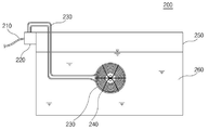
3 is a front view showing a plating apparatus heater apparatus according to the present invention,
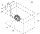
4 is a perspective view showing a plating apparatus heater apparatus according to the present invention;
FIG. 5 is a perspective view illustrating the heating unit illustrated in FIGS. 3 and 4.
Hereinafter, embodiments of the present invention will be described in detail with reference to the accompanying drawings. Prior to this, terms and words used in the present specification and claims should not be construed as limited to ordinary or dictionary terms, and the inventor should appropriately interpret the concept of the term appropriately in order to describe its own invention in the best way. The present invention should be construed in accordance with the meaning and concept consistent with the technical idea of the present invention.
Therefore, the embodiments described in this specification and the configurations shown in the drawings are merely the most preferred embodiments of the present invention and do not represent all the technical ideas of the present invention. Therefore, It is to be understood that equivalents and modifications are possible.
3 is a front view showing a plating apparatus heater apparatus according to the present invention. 4 is a perspective view showing a plating apparatus heater apparatus according to the present invention. FIG. 5 is a perspective view illustrating the heater illustrated in FIGS. 3 and 4.
3 to 5, the plating apparatus heater apparatus 200 (hereinafter, referred to as a heater apparatus) according to the present invention includes a
The
The
The
In addition, the
In particular, according to the present invention, in order to maintain the temperature of the plating
The
The
The
The
As described above, although the present invention has been described by means of a limited embodiment and drawings, the present invention is not limited thereto and by those skilled in the art to which the present invention pertains, Of course, various modifications and variations are possible within the scope of equivalents of the claims to be described.
200: heater device
210: cable 220: controller
230: heating portion 240: fixed portion
241: central axis 242: fixed plate
243: fixing hole 250: plating bath
260: plating solution
Claims (7)
A fixing part for fixing the shape by winding the heating part in a plurality of circle shapes;
Plating bath heater apparatus comprising a.
The surface of the heating portion,
Plating bath heater apparatus characterized in that formed of a thermosetting resin containing a Teflon tube.
The inside of the heating unit,
Plating bath heater device characterized in that to maintain a vacuum state.
The inside of the heating unit,
Plating bath heater device characterized in that the heating element is formed by inserting a nichrome wire.
The fixing unit includes:
A plurality of fixing plates formed on the basis of the central axis;
A fixing hole into which the heating part is inserted into the plurality of fixing plates;
Plating bath heater apparatus comprising a.
The fixing unit includes:
Plating bath heater apparatus, characterized in that formed with a thermosetting resin.
The heating unit,
Plating bath heater apparatus characterized in that it generates heat in a temperature range of 145 ~ 250 ℃.
Priority Applications (1)
| Application Number | Priority Date | Filing Date | Title |
|---|---|---|---|
| KR1020110038816A KR20120121069A (en) | 2011-04-26 | 2011-04-26 | Heater Apparatus For Heating Plating Tank |
Applications Claiming Priority (1)
| Application Number | Priority Date | Filing Date | Title |
|---|---|---|---|
| KR1020110038816A KR20120121069A (en) | 2011-04-26 | 2011-04-26 | Heater Apparatus For Heating Plating Tank |
Publications (1)
| Publication Number | Publication Date |
|---|---|
| KR20120121069A true KR20120121069A (en) | 2012-11-05 |
Family
ID=47507588
Family Applications (1)
| Application Number | Title | Priority Date | Filing Date |
|---|---|---|---|
| KR1020110038816A KR20120121069A (en) | 2011-04-26 | 2011-04-26 | Heater Apparatus For Heating Plating Tank |
Country Status (1)
| Country | Link |
|---|---|
| KR (1) | KR20120121069A (en) |
Cited By (1)
| Publication number | Priority date | Publication date | Assignee | Title |
|---|---|---|---|---|
| CN104389009A (en) * | 2014-11-28 | 2015-03-04 | 江门市宏丰电子科技有限公司 | Electroplating solution heating tank |
-
2011
- 2011-04-26 KR KR1020110038816A patent/KR20120121069A/en not_active Application Discontinuation
Cited By (1)
| Publication number | Priority date | Publication date | Assignee | Title |
|---|---|---|---|---|
| CN104389009A (en) * | 2014-11-28 | 2015-03-04 | 江门市宏丰电子科技有限公司 | Electroplating solution heating tank |
Similar Documents
| Publication | Publication Date | Title |
|---|---|---|
| RU2019142109A (en) | CAVITY HEATING UNIT | |
| KR20120121069A (en) | Heater Apparatus For Heating Plating Tank | |
| KR20120083311A (en) | Electrolytic device | |
| ES2573280T3 (en) | Zeolite coating preparation set and operating procedure | |
| KR101502748B1 (en) | heating pipe | |
| CN105571114B (en) | A kind of novel immersion heating electrode | |
| JP3184097U (en) | Fluid heating device | |
| EA201600129A1 (en) | METHOD AND DEVICE FOR OBTAINING HEAT ENERGY BY PLASMA ELECTROLYSIS | |
| CN203909647U (en) | Self-heating thermostat | |
| CN204535118U (en) | A kind of modified node method of electric heating part of liquid heater of nonmetallic vessel | |
| US20100140254A1 (en) | Aquarium heater | |
| KR101158011B1 (en) | An electric heating apparatus | |
| KR101521814B1 (en) | Induction boiler and hybrid hot water supply and heating system using it | |
| KR102406883B1 (en) | Thermoelectric generator for heating container | |
| US20190075767A1 (en) | Flat heater | |
| MX2020004395A (en) | An electric current supply system, designed to be at least partially submerged in an electrically conductive liquid during operation thereof. | |
| CN104010397B (en) | A kind of FLiNaK fused salt electric heater for thorio nuclear power system | |
| KR20200034263A (en) | Electrolysis Type Water Heating Apparatus and Radiator System using thereof | |
| KR101522709B1 (en) | Hybrid using system by photovoltaic solar | |
| CN203928099U (en) | A kind of electric heater of replacing fuse for convenience detach | |
| CN211395093U (en) | Hanging ironing machine | |
| CN209890717U (en) | Galvanization plating assisting box | |
| US20200340709A1 (en) | Fluid heating device | |
| RU2762684C1 (en) | Current supply output design and electromagnetic device | |
| CN106805759A (en) | A kind of insulating pot with heat-insulating base |
Legal Events
| Date | Code | Title | Description |
|---|---|---|---|
| A201 | Request for examination | ||
| E601 | Decision to refuse application |