KR20120119036A - Solar cell plate structures for ceiling space - Google Patents
Solar cell plate structures for ceiling space Download PDFInfo
- Publication number
- KR20120119036A KR20120119036A KR1020110036759A KR20110036759A KR20120119036A KR 20120119036 A KR20120119036 A KR 20120119036A KR 1020110036759 A KR1020110036759 A KR 1020110036759A KR 20110036759 A KR20110036759 A KR 20110036759A KR 20120119036 A KR20120119036 A KR 20120119036A
- Authority
- KR
- South Korea
- Prior art keywords
- solar cell
- base plate
- slab
- cell plate
- plate
- Prior art date
Links
- 239000011521 glass Substances 0.000 claims description 22
- 230000003028 elevating effect Effects 0.000 claims description 12
- 239000011229 interlayer Substances 0.000 claims description 9
- 230000008014 freezing Effects 0.000 claims description 3
- 238000007710 freezing Methods 0.000 claims description 3
- 238000000034 method Methods 0.000 claims 2
- 230000000903 blocking effect Effects 0.000 claims 1
- 230000002265 prevention Effects 0.000 claims 1
- 238000009413 insulation Methods 0.000 description 5
- 238000012423 maintenance Methods 0.000 description 5
- 238000003780 insertion Methods 0.000 description 4
- 230000037431 insertion Effects 0.000 description 4
- 230000000694 effects Effects 0.000 description 3
- 238000005286 illumination Methods 0.000 description 2
- 238000010276 construction Methods 0.000 description 1
- 230000006866 deterioration Effects 0.000 description 1
- 230000005611 electricity Effects 0.000 description 1
- 238000010438 heat treatment Methods 0.000 description 1
- 239000011810 insulating material Substances 0.000 description 1
- 238000004519 manufacturing process Methods 0.000 description 1
- 239000000463 material Substances 0.000 description 1
- 238000012986 modification Methods 0.000 description 1
- 230000004048 modification Effects 0.000 description 1
- 230000003252 repetitive effect Effects 0.000 description 1
Images

Classifications
-
- H—ELECTRICITY
- H02—GENERATION; CONVERSION OR DISTRIBUTION OF ELECTRIC POWER
- H02S—GENERATION OF ELECTRIC POWER BY CONVERSION OF INFRARED RADIATION, VISIBLE LIGHT OR ULTRAVIOLET LIGHT, e.g. USING PHOTOVOLTAIC [PV] MODULES
- H02S20/00—Supporting structures for PV modules
- H02S20/20—Supporting structures directly fixed to an immovable object
- H02S20/22—Supporting structures directly fixed to an immovable object specially adapted for buildings
-
- H—ELECTRICITY
- H02—GENERATION; CONVERSION OR DISTRIBUTION OF ELECTRIC POWER
- H02S—GENERATION OF ELECTRIC POWER BY CONVERSION OF INFRARED RADIATION, VISIBLE LIGHT OR ULTRAVIOLET LIGHT, e.g. USING PHOTOVOLTAIC [PV] MODULES
- H02S20/00—Supporting structures for PV modules
- H02S20/30—Supporting structures being movable or adjustable, e.g. for angle adjustment
-
- H—ELECTRICITY
- H02—GENERATION; CONVERSION OR DISTRIBUTION OF ELECTRIC POWER
- H02S—GENERATION OF ELECTRIC POWER BY CONVERSION OF INFRARED RADIATION, VISIBLE LIGHT OR ULTRAVIOLET LIGHT, e.g. USING PHOTOVOLTAIC [PV] MODULES
- H02S99/00—Subject matter not provided for in other groups of this subclass
-
- Y—GENERAL TAGGING OF NEW TECHNOLOGICAL DEVELOPMENTS; GENERAL TAGGING OF CROSS-SECTIONAL TECHNOLOGIES SPANNING OVER SEVERAL SECTIONS OF THE IPC; TECHNICAL SUBJECTS COVERED BY FORMER USPC CROSS-REFERENCE ART COLLECTIONS [XRACs] AND DIGESTS
- Y02—TECHNOLOGIES OR APPLICATIONS FOR MITIGATION OR ADAPTATION AGAINST CLIMATE CHANGE
- Y02B—CLIMATE CHANGE MITIGATION TECHNOLOGIES RELATED TO BUILDINGS, e.g. HOUSING, HOUSE APPLIANCES OR RELATED END-USER APPLICATIONS
- Y02B10/00—Integration of renewable energy sources in buildings
- Y02B10/10—Photovoltaic [PV]
-
- Y—GENERAL TAGGING OF NEW TECHNOLOGICAL DEVELOPMENTS; GENERAL TAGGING OF CROSS-SECTIONAL TECHNOLOGIES SPANNING OVER SEVERAL SECTIONS OF THE IPC; TECHNICAL SUBJECTS COVERED BY FORMER USPC CROSS-REFERENCE ART COLLECTIONS [XRACs] AND DIGESTS
- Y02—TECHNOLOGIES OR APPLICATIONS FOR MITIGATION OR ADAPTATION AGAINST CLIMATE CHANGE
- Y02B—CLIMATE CHANGE MITIGATION TECHNOLOGIES RELATED TO BUILDINGS, e.g. HOUSING, HOUSE APPLIANCES OR RELATED END-USER APPLICATIONS
- Y02B10/00—Integration of renewable energy sources in buildings
- Y02B10/20—Solar thermal
-
- Y—GENERAL TAGGING OF NEW TECHNOLOGICAL DEVELOPMENTS; GENERAL TAGGING OF CROSS-SECTIONAL TECHNOLOGIES SPANNING OVER SEVERAL SECTIONS OF THE IPC; TECHNICAL SUBJECTS COVERED BY FORMER USPC CROSS-REFERENCE ART COLLECTIONS [XRACs] AND DIGESTS
- Y02—TECHNOLOGIES OR APPLICATIONS FOR MITIGATION OR ADAPTATION AGAINST CLIMATE CHANGE
- Y02E—REDUCTION OF GREENHOUSE GAS [GHG] EMISSIONS, RELATED TO ENERGY GENERATION, TRANSMISSION OR DISTRIBUTION
- Y02E10/00—Energy generation through renewable energy sources
- Y02E10/50—Photovoltaic [PV] energy
- Y02E10/52—PV systems with concentrators
Landscapes
- Engineering & Computer Science (AREA)
- Architecture (AREA)
- Civil Engineering (AREA)
- Structural Engineering (AREA)
- Photovoltaic Devices (AREA)
- Special Wing (AREA)
Abstract
Description
본 발명은 태양전지 플레이트에 관한 것으로서, 보다 상세하게는 건물의 슬라브 외측에 설치되는 층방용 태양전지 플레이트구조에 관한 것이다.The present invention relates to a solar cell plate, and more particularly, to a layered solar cell plate structure installed outside the slab of a building.
일반적으로, 많은 빌딩들이 과거의 단순 슬라브 및 벽체 구조에서 탈피하여 미려하고 투명한 건물 외장을 위해 커튼월 구조를 채택하고 있다. 이러한 커튼월 구조에서는 일반적으로 슬라브와 커튼월 사이에서 공간이 발생되므로 그 공간을 마감 하기 위해 마감 플레이트가 사용된다. 하지만 마감 플레이트는 상당한 면적을 차지함에도 불구하고 마감재 및 층간방화의 용도로만 사용되고 있다. In general, many buildings have moved away from simple slab and wall structures of the past and have adopted curtain wall structures for beautiful and transparent building exteriors. In such a curtain wall structure, a space is generally generated between the slab and the curtain wall, so a finishing plate is used to close the space. However, the finishing plate occupies a considerable area, but is only used for finishing and interlayer fire protection.
최근에는, 마감재로서의 용도뿐만 아니라, 전력의 생산 및 저장의 용도를 겸할 수 있는 태양전지 플레이트를 설치하여 사용하고 있다. 이러한 태양전지 플레이트는 상기 마감 플레이트에 전면에 고정되거나, 또는 건물의 외벽에 설치되어 태양광을 집광하는데 사용되고 있다. 하지만 이러한 태양전지 플레이트는 미감이 저하되며, 상당한 면적을 차지할 뿐더러 해가 뜨지 않는 저녁이나 흐린 날씨에는 태양을 집광할 수 없게 되어 효율성이 떨어지는 단점이 있다. 또한 천정의 유지보수시 태양전지플레이트에 의해 간섭되어 공기가 길어지고 따라서 보수비용이 증대되는 문제점이 발생되었다.In recent years, the solar cell plate which can serve not only as a finishing material but also as an electric power production and storage is provided and used. The solar cell plate is fixed to the front surface of the finishing plate, or is installed on the outer wall of the building is used to collect sunlight. However, such a solar cell plate has a deterioration of aesthetics, occupies a considerable area, and has a disadvantage in that efficiency is not reduced because it is impossible to collect the sun in the evening or cloudy weather when the sun does not rise. In addition, the maintenance of the ceiling interfered with the solar cell plate has caused a problem that the air is long and thus the maintenance cost increases.
본 발명은, 건물의 슬라브 외측에 설치되는 층방용 태양전지 플레이트구조를 제공하는 것을 목적으로 한다.An object of the present invention is to provide a solar cell plate structure for floors installed on the outside of a slab of a building.
본 발명은, 건물 유리창의 내측과 이격된 슬라브의 외측에 결합되는 고정부재와 상기 고정부재의 하단에서 회동가능하게 결합되는 판 형상의 베이스 플레이트 및 태양광을 집광할 수 있도록 상기 베이스 플레이트의 외측에 고정되는 태양전지판을 포함하는 층방용 태양전지 플레이트를 제공한다.The present invention, the fixing member is coupled to the outside of the slab spaced apart from the inner side of the building glass window and the plate-shaped base plate and the outside of the base plate so as to focus the rotatably coupled to the lower end of the fixing member Provided is a layered solar cell plate including a fixed solar cell plate.
또한 본 발명의 다른 측면에 따르면 본 발명은, 건물 유리창의 내측과 이격된 슬라브의 외측에 결합되는 승강부재와 상기 승강부재의 일 측에서 2단 결합되어 상하 슬라이딩되는 판 형상의 제1,제2베이스 플레이트 및 태양광을 집광할 수 있도록 상기 베이스 플레이트의 외측에 각가 고정되는 제1,제2태양전지판을 포함하는 층방용 태양전지 플레이트를 제공한다.According to another aspect of the present invention, the present invention, the first and second plate-like member which is coupled to the lifting member coupled to the outer side of the slab spaced apart from the inner side of the building glass and one side of the lifting member sliding up and down Provided is a layered solar cell plate including a base plate and a first and a second solar panel, the angle of which is fixed to the outside of the base plate to collect the sunlight.
본 발명에 있어서, 상기 고정부재의 전방에 배치되어 상기 슬라브와 상기 유리창 사이에서 동결을 방지하는 히트파이프를 더 포함할 수 있다.In the present invention, it may further include a heat pipe disposed in front of the fixing member to prevent freezing between the slab and the glass window.
또한 본 발명에 있어서, 상기 고정부재의 상부에 위치하며 상기 슬라브와 상기 유리창 사이에서 층간 방화를 차단하는 방화부재를 포함할 수 있다.In addition, in the present invention, it may include a fire protection member positioned on the fixing member to block the interlayer fire between the slab and the glass window.
또한 본 발명에 있어서, 상기 슬라브의 일 측에 위치하며 상기 태양전지판으로부터 집광된 태양에너지를 전기 에너지로 변환하여 건물에서 필요한 곳에 전원을 공급해 주는 전원공급부를 포함할 수 있다.In addition, in the present invention, and located on one side of the slab may include a power supply for converting the solar energy collected from the solar panel into electrical energy to supply power where necessary in the building.
본 발명에 따른 층방용 태양전지 플레이트구조는, 다음과 같은 효과를 가진다.The layered solar cell plate structure according to the present invention has the following effects.
첫째, 외부에 노출형태를 내부에 삽입하면서 미감과 함께 안전성이 확보됨.First, safety is secured with the sense of aesthetic by inserting the exposure form inside.
둘째, 태양전지 플레이트는 접이식 및 슬라이드 방식이기 때문에 흐린 날이나, 저녁에는 상부로 이동되거나 접혀지므로 층방의 공간을 효율적으로 활용할 수 있다.Second, since the solar cell plate is foldable and slide type, it is moved or folded to the upper part in a cloudy day or in the evening, so that the space of the floor can be efficiently used.
셋째, 층방의 유지보수 시 별도로 해체하지 않아도 되므로, 시공 기간이 단축되어 인건비 및 수리비용이 감소된다.Third, there is no need to dismantle separately during maintenance of the floor, the construction period is shortened, reducing labor and repair costs.
넷째, 상기 유리창과 슬라브 사이에는 단열부재가 매설되어, 층간 단열기능을 갖는다.Fourth, the insulating member is embedded between the glass window and the slab, has an interlayer insulation function.
다섯째, 상기 유리창과 슬라브 사이에는 방화부재가 배치되어 화재 시 층간 화재를 방지한다.Fifth, the fire protection member is disposed between the glass window and the slab to prevent the inter-layer fire during the fire.
여섯째, 신축건물뿐 아니라 기존건물(아파트, 빌딩, 빌라, 주택)에도 적용이 가능하므로, 집광된 에너지의 활용이 어디서든 가능하다.
Sixth, as it can be applied to existing buildings (apartments, buildings, villas, houses) as well as new buildings, it is possible to use the concentrated energy anywhere.
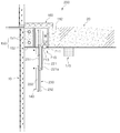
도 1은 본 발명의 일실시예에 따른 층방용 태양전지 플레이트의 사용상태를 나타낸 단면도이다.
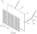
도 2는 도 1의 층방용 태양전지 플레이트의 사시도이다.
도 3은 본 발명의 다른 실시예에 따른 층방용 태양전지 플레이트의 사용상태 단면도이다.
도 4는 도 3의 층방용 태양전지 플레이트의 사시도도이다.1 is a cross-sectional view showing a state of use of the solar cell plate for a floor according to an embodiment of the present invention.
FIG. 2 is a perspective view of the solar cell plate of FIG. 1.
Figure 3 is a cross-sectional view of the use state of the solar cell plate for a floor according to another embodiment of the present invention.
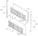
FIG. 4 is a perspective view of the solar cell plate of FIG. 3.
이하, 첨부된 도면을 참조로 본 발명의 바람직한 실시예들을 상세히 설명하기로 한다. Hereinafter, exemplary embodiments of the present invention will be described in detail with reference to the accompanying drawings.
도1은 본 발명의 일실시예에 따른 층방용 태양전지 플레이트구조(100)의 사용상태 단면도이고, 도 2는 도 1의 층방용 태양전지 플레이트구조(100)의 사시도이다. 1 is a cross-sectional view illustrating a state of use of a solar
도 1 및 도 2를 참조하면, 상기 층방용 태양전지 플레이트구조(100)는 고정부재(110)와 베이스플레이트(120)와 접철부재(130), 태양전지판(140)과 단열부재(150)와 방화부재(160) 및 전원공급부(170)를 포함한다. 1 and 2, the layered solar
상기 고정부재(110)는, 케이스(111) 및 구동부(112)를 포함한다. The
상기 케이스(111)는 건물의 유리창(10)과 이격된 슬라브(20)사이에서, 상기 슬라브(20)의 외측에 결합된다. 여기서 상기 케이스(111)는, 직육면체 형상에 하부는 개방되고, 내측으로 구동부(112)가 삽입된다.The
상기 구동부(112)는, 후술할 베이스플레이트(120)의 상부를 결합하며, 상기 베이스플레이트(120)를 상대회전가능하게 동작시키는 역할을 수행한다. The
상기 베이스플레이트(120)는, 삽입홈(121)을 포함한다. The
상기 베이스플레이트(120)는, 직육면체의 판 형상으로 형성되며 길이방향으로 상부에 상기 삽입홈(121)이 구비된다. 이러한 상기 삽입홈(121)은, 상기 구동부(112)의 회전축이 삽입되도록 설정된 깊이의 홈(121)으로 형성된다. 따라서 상기 구동부(112)의 회전력을 전달받은 상기 베이스플레이트(120)는, 상기 케이스(111)의 하단에서 상대회전하게 된다. The
이때, 상기 베이스플레이트(120)의 양 측면에는 상기 구동부(112)에 의해 상기 베이스플레이트(120)가 회동 시 안정성을 갖으며 동시에 용이하게 회동하도록 접철부재(130)가 결합된다.At this time, both sides of the
상기 접철부재(130)는, 제1패널(131)과 제2패널(132) 및 힌지(133)를 포함한다. 여기서 상기 제1패널(131)은, 일 측이 상기 베이스플레이트(120)의 일 측면에 회동가능하게 결합되며, 타 측이 상기 제2패널(132)의 일 측 힌지(133)에 결합된다. 또한 상기 제2패널(132)의 타 측은 상기 슬라브(20)의 하단 일 측에 회동가능하게 결합된다. 이러한 상기 제1패널(131)과 제2패널(132)은 중앙의 힌지(133)와 함께 회동되며 아울러 상기 베이스플레이트(120)가 안정성을 갖고 회동될 수 있도록 가이드 역할을 수행한다.The
상기 태양전지판(140)은, 태양광을 집광할 수 있도록 상기 베이스플레이트(120)의 외측에 고정된다. 여기서 상기 태양전지판(140)은, 상기 베이스플레이트(120)의 외측에 고정될 수도 있고, 상기 베이스플레이트(120)에 개구부를 형성하여 그 개구부에 삽입, 고정될 수도 있다. 이러한 상기 태양전지판(140)은 전 후 측의 투명유리(141)에 감싸져 배열되는 단위 셀들(142)에 의해 태양에너지를 전기적 에너지로 생산하게 되는 것이다. 또한 상기 태양전지판(140)은, 태양으로부터 집광된 태양에너지를 난방에너지로 전환하여 후술할 단열부재(150)에 열을 전달하는 역할을 수행한다.The
상기 단열부재(150)는 히트파이프(151)와 하우징(152)을 포함한다. The
상기 단열부재(150)는 상기 고정부재(110)와 상기 유리창(10) 사이에서 배치된다. 이러한 상기 단열부재(150)는, 겨울철 또는 온도가 급격이 하강할 때 상기 유리창(10)과 상기 고정부재(110)의 동결을 방지하는 동시에 층간 단열의 기능의 역할을 수행한다. 여기서 상기 히트파이프(151)는, 상기 하우징(152)의 내측에 삽입된다. The
상기 하우징(152)은, 직육면체 형상으로 내측에 상기 히트파이프(151)를 구비한다. 또한 상기 히트파이프(151)와 상기 하우징(152) 사이에 열전달이 우수하며 동시에 안정성을 갖도록 단열소재가 발포된다.The
상기 방화부재(160)는, 상기 고정부재(110)의 상부에 위치하며 상기 슬라브(20)와 상기 유리창(10) 사이에서 배치된다. 이러한 상기 방화부재(160)는, 화재시 층간 방화를 차단하는 역할을 수행한다.The
상기 전원공급부(170)는 상기 슬라브(20)의 하단 일 측에 배치된다. 이러한 상기 전원공급부(170)는 태양으로부터 집광된 태양에너지를 전기에너지로 변환하여 전기를 생산한다. 여기서 상기 전원공급부(170)는 "대한민국 공개특허(공개번호: 10-2010-0113900)"에 도시된 전원공급부와 동일한 구성이므로, 작동원리는 생략한다.The
상술한 바와 같이 상기 층방용 태양전지 플레이트구조(100)는, 저녁이나 날씨가 흐린 날 즉, 태양을 집광할 수 없는 경우는 상기 구동부(112)가 동작되어 상기 베이스플레이트(120)를 상기 슬라브(20)의 하단에 위치시킨다. 또한, 태양을 집광하게 되는 경우에는 반대로 회동시켜 상기 유리창(10)과 동일한 수직상태로 설정한다. As described above, in the solar
한편, 본 발명은 이에 한정하지 않고, 상기 고정부재(110)는, 상기 유리창(10)의 내측에 인접하며 상기 단열부재(150)의 전면에 배치될 수 있다. 이러한 이유는 상기 고정부재(110)의 하단에 위치한 상기 태양전지판(140)이 상기 단열부재(150)에 의해 간섭되는 것을 방지하고, 모든 면적으로 태양을 집광하기 위해서이다.On the other hand, the present invention is not limited to this, the
또 한편, 상기 층방용 태양전지 플레이트구조(100)는, 수평방향에서 수직방향인 90ㅀ방향으로 한 번에 회동될 수도 있고, 태양의 방향을 따라 더 넓은 각도로 이동될 수도 있다. 즉, 태양의 조도 방향이 달라짐에 따라, 상기 태양을 따라 이동하며, 모든 면적으로 태양광을 집광하기 위해서이다. 이러한 상기 층방용 태양전지 플레이트구조(100)는, 사용자가 수동으로 동작시킬 수도 있고, 자동에 의한 동작도 가능하다. 즉, 타이머에 의해 동작되거나 또는 센서에 의해 동작될 수 있다.On the other hand, the layered solar
따라서 상기 층방용 태양전지 플레이트구조(100)는, 날씨나 기후조건에 따라 회동되어 층방의 공간 활용이 가능하며, 또한 유지보수가 용이하고 미감을 일으키는 장점을 갖는다. 또한 단열기능과 함께 층간 방화기능을 동시 수반하는 효과를 갖는다. Therefore, the layered solar
도 3 및 도 4 에는, 본 발명의 다른 실시 예에 따른, 층방용 태양전지 플레이트구조(200)가 도시되어 있다. 도 3은 본 발명의 다른 실시예에 따른 층방용 태양전지 플레이트구조(200)의 사용상태 단면도이고, 도 4는 도 3의 층방용 태양전지 플레이트구조(200)의 사시도이다. 한편, 도 1 및 도 2에 나타낸 참조부호와 동일한 참조부호는 동일한 구조 및 작용을 하는 동일한 부재이므로 반복적인 설명은 생략하도록 한다. 3 and 4, the solar
도 3 및 도 4를 참조하면, 상기 층방용 태양전지 플레이트구조(200)는 승강부재(210)와 베이스플레이트(220)와 스텝암(230)과 태양전지판(140)과 단열부재(150)와 방화부재(160) 및 전원공급부(170)를 포함한다. 3 and 4, the layered solar
상기 승강부재(210)는, 케이스(211)와 구동부(212) 및 기어(213)를 포함한다.The elevating
상기 케이스(211)는 건물의 유리창(10)과 이격된 슬라브(20)사이에서, 상기 슬라브(20)의 외측에 결합된다. 여기서 상기 케이스(211)는, 직육면체 형상에 하부는 개방되고, 내측으로 구동부(212)가 삽입된다. The
상기 구동부(212)는, 상기 기어(213)에 회전력을 전달하는 기능을 수행한다. The driving unit 212 performs a function of transmitting a rotational force to the
상기 기어(213)는 상기 구동부(212)의 회전축 둘레에 결합된다. 이러한 상기 기 기어(213)는 후술할 제1베이스플레이트(221)의 후면에 결합된 레일(221a)과 맞물려 상기 베이스플레이트(220)를 상하 이동시킨다. The
상기 베이스플레이트(220)는, 제1베이스플레이트(221) 및 제2베이스플레이트(222)를 포함한다. 상기 제1베이스플레이트(221)는, 직육면체의 판 형상으로 후면에 높이방향으로 레일(221a)이 결합된다. 이러한 상기 레일(221a)은 후단의 상기 기어(213)와 맞물려 제1베이스플레이트(221)와 함께 상하 승강된다.The base plate 220 includes a
상기 제2베이스플레이트(222)는 상기 제1베이스플레이트(221)의 전면에 위치하며 후술할 스텝암(230)에 의해 상하 이동된다.The
상기 스템압(230)은 제1바(231)와 제2바(232)를 포함한다. 여기서 상기 제1바(231)는 바(bar)형상으로 내부에 중공이 형성된다. 또한 상부 일 측은 상기 제1베이스플레이트(221)의 상부 일 측면에 고정된다. The
상기 제2바(232)는 바(bar) 형상에 상기 제1바(231)의 내부 중공에 슬라이딩 이동 가능하게 삽입된다. 또한 상기 제2바(232)는 일 측이 상기 제2베이스플레이트(222)의 하부 일 측면에 고정된다. 이러한 상기 스템압(230)은 상기 제1베이스플레이트(221)가 상기 승강부재(210)서 하단으로 상기 구동부(212)에 의해 이동되면, 상기 제2베이스플레이트(222)가 하단으로 2단 이동되는 2단 길이 조정의 역할을 수행한다. The
상기 태양전지판(140)은, 본 발명의 일실시예에 상술한 상기 태양전지판(140)과 유사한 구성이므로 상세한 설명은 생략한다.Since the
상기 단열부재(150)는 상기 승강부재(210)와 상기 유리창(10) 사이에서 배치된다. 여기서 상기 단열부재(150)는, 본 발명의 일실시예에 상술한 상기 단열부재(150)와 유사한 구성이므로 상세한 설명은 생략한다.The
상기 방화부재(160)는, 상기 승강부재(210)의 상부에 위치하며 상기 슬라브(20)와 상기 유리창(10) 사이에서 배치된다. 이러한 상기 방화부재(160)는, 본 발명의 일실시예에 상술한 상기 방화부재(150)와 유사한 구성이므로 상세한 설명은 생략한다.The
상기 전원공급부(170)는 본 발명의 일실시예에 상술한 상기 전원공급부(170)와 유사한 구성이므로 상세한 설명은 생략한다.Since the
상술한 바와 같이 상기 층방용 태양전지 플레이트구조(200)는, 상기 제1베이스플레이트(221)의 후면에 결합된 레일(221a)이 상기 승강부재(210)의 구동부(212)에 의해 상하 승강된다. 또한 상기 스텝암(230)에 의해 상기 제2베이스플레이트(222)가 하단으로 2단 이동된다. 이러한 층방용 태양전지 플레이트구조(200)는 저녁이나 날씨가 흐린 날, 즉 태양을 집광할 수 없는 경우에는 상기 승강부재(210)의 내측에 삽입된다. 또한 태양을 집광하게 될 경우에는, 상기 구동부(212)가 회동되어 상기 베이스플레이트(220)들을 상기 승강부재(210)의 하측으로 하강시킨다. As described above, in the solar
하지만, 본 발명은 이에 한정하지 않고, 상기 제2베이스플레이트(222)는 다양하게 상하로 이동될 수 있다. 예를 들어, 실린더 등에 의해 승 하강 될 수 있다.However, the present invention is not limited thereto, and the
또한 상기 승강부재(210)는, 상기 유리창(10)의 내측에 인접하며 상기 단열부재(150)의 전면에 배치될 수 있다. 이러한 이유는 상기 승강부재(210)의 하단에 위치한 상기 태양전지판(140)이 상기 단열부재(150)에 의해 간섭되는 것을 방지하고, 모든 면적으로 태양을 집광하기 위해서이다. 즉 태양의 조도 방향이 달라짐에 따라 상기 태양을 따라 이동하여 모든 면적으로 태양광을 집광하기 위함이다. 또한 상기 층방용 태양전지 플레이트구조(100)는, 태양의 조도 방향에 따라 상기 제2베이스플레이트(222)는 선택적으로 이동이 가능하다. 이 또한 태양의 조도 방향이 달라짐에 따라 상기 태양을 따라 상하 이동하여 모든 면적으로 태양광을 집광하기 위해서이다. 이러한 상기 층방용 태양전지 플레이트구조(100)는, 사용자가 수동으로 동작시킬 수도 있고, 자동에 의한 동작도 가능하다. 즉, 타이머에 의해 동작되거나 또는 센서에 의해 동작될 수 있다.In addition, the elevating
따라서 상기 층방용 태양전지 플레이트구조(100)는, 날씨나 기후조건에 따라 승 하강되어 층방의 공간 활용이 가능하며, 또한 유지보수가 용이하고 미감을 일으키는 장점을 갖는다. 또한 단열기능과 함께 층간 방화기능을 동시 수반하는 효과를 갖는다.
Therefore, the layered solar
본 발명은 도면에 도시된 실시 예를 참고로 설명되었으나 이는 예시적인 것에 불과하며, 본 기술 분야의 통상의 지식을 가진 자라면 이로부터 다양한 변형 및 균등한 다른 실시예가 가능하다는 점을 이해할 것이다. 따라서 본 발명의 진정한 기술적 보호 범위는 첨부된 특허청구범위의 기술적 사상에 의하여 정해져야 할 것이다. While the present invention has been described with reference to exemplary embodiments, it is to be understood that the invention is not limited to the disclosed exemplary embodiments, but, on the contrary, is intended to cover various modifications and equivalent arrangements included within the spirit and scope of the appended claims. Therefore, the true technical protection scope of the present invention will be defined by the technical spirit of the appended claims.
100, 200: 층방용 태양전지 플레이트구조 110: 고정부재
111: 케이스 112: 구동부
120: 베이스플레이트 121: 삽입홈
130: 접철부재 131: 제1패널
132: 제2패널 133: 힌지
140: 태양전지판 141: 투명유리
142: 셀 150: 단열부재
151: 히트파이프 152: 하우징
160: 방화부재 170: 전원공급부 210: 승강부재 211: 기어 212: 구동부 220: 베이스플레이트
221a: 레일 100, 200: layered solar cell plate structure 110: fixing member
111: case 112: drive unit
120: base plate 121: insertion groove
130: folding member 131: the first panel
132: second panel 133: hinge
140: solar panel 141: transparent glass
142: cell 150: insulation member
151: heat pipe 152: housing
160: fire protection member 170: power supply unit 210: elevating member 211: gear 212: drive unit 220: base plate
221a: rail
Claims (4)
상기 고정부재의 하단에서 회동가능하게 결합되는 판 형상의 베이스 플레이트; 및
태양광을 집광할 수 있도록 상기 베이스 플레이트의 외측에 고정되는 태양전지판을 포함하는 층방용 태양전지 플레이트.A fixing member coupled to the outside of the slab spaced apart from the inside of the building glass window;
A plate-shaped base plate rotatably coupled at a lower end of the fixing member; And
A solar cell plate for a floor including a solar panel is fixed to the outside of the base plate to collect sunlight.
상기 승강부재의 일 측에서 2단 결합되어 상하 슬라이딩되는 판 형상의 제1,제2베이스 플레이트; 및
태양광을 집광할 수 있도록 상기 베이스 플레이트의 외측에 고정되는 제1,제2태양전지판을 포함하는 층방용 태양전지 플레이트.An elevating member coupled to an outer side of the slab spaced apart from the inner side of the building glass window;
First and second base plates of a plate shape which are coupled in two stages on one side of the elevating member and vertically slid; And
A solar cell plate for a floor comprising a first, a second solar panel is fixed to the outside of the base plate to collect sunlight.
상기 고정부재의 전방에 배치되어 상기 슬라브와 상기 유리창 사이에서 동결을 방지하는 히트파이프를 더 포함하는 층방용 태양전지 플레이트. The method according to claim 1 or 2,
And a heat pipe disposed in front of the fixing member to prevent freezing between the slab and the glass window.
상기 고정부재의 상부에 위치하며 상기 슬라브와 상기 유리창 사이에서 층간 방화를 차단하는 방화부재를 포함하는 층방용 태양전지 플레이트. The method according to claim 1 or 2,
Located on top of the fixing member and the solar cell plate for a room including a fire prevention member for blocking the interlayer fire between the slab and the glass window.
Priority Applications (1)
| Application Number | Priority Date | Filing Date | Title |
|---|---|---|---|
| KR1020110036759A KR101209773B1 (en) | 2011-04-20 | 2011-04-20 | Solar cell plate Structures for ceiling space |
Applications Claiming Priority (1)
| Application Number | Priority Date | Filing Date | Title |
|---|---|---|---|
| KR1020110036759A KR101209773B1 (en) | 2011-04-20 | 2011-04-20 | Solar cell plate Structures for ceiling space |
Publications (2)
| Publication Number | Publication Date |
|---|---|
| KR20120119036A true KR20120119036A (en) | 2012-10-30 |
| KR101209773B1 KR101209773B1 (en) | 2012-12-07 |
Family
ID=47286360
Family Applications (1)
| Application Number | Title | Priority Date | Filing Date |
|---|---|---|---|
| KR1020110036759A KR101209773B1 (en) | 2011-04-20 | 2011-04-20 | Solar cell plate Structures for ceiling space |
Country Status (1)
| Country | Link |
|---|---|
| KR (1) | KR101209773B1 (en) |
Families Citing this family (2)
| Publication number | Priority date | Publication date | Assignee | Title |
|---|---|---|---|---|
| KR101973397B1 (en) * | 2017-10-24 | 2019-04-30 | 한국건설기술연구원 | Solar power generation Module storage case |
| KR101951720B1 (en) * | 2017-10-24 | 2019-02-25 | 한국건설기술연구원 | Photovoltaic devices |
Family Cites Families (1)
| Publication number | Priority date | Publication date | Assignee | Title |
|---|---|---|---|---|
| KR100796245B1 (en) * | 2006-11-29 | 2008-01-21 | 주식회사 이건창호시스템 | High- efficiency automatic twofolded-window for building integrated photovoltaic system |
-
2011
- 2011-04-20 KR KR1020110036759A patent/KR101209773B1/en not_active IP Right Cessation
Also Published As
| Publication number | Publication date |
|---|---|
| KR101209773B1 (en) | 2012-12-07 |
Similar Documents
| Publication | Publication Date | Title |
|---|---|---|
| CN103362255B (en) | Intelligence skylight, a kind of solar energy list slope | |
| KR101001789B1 (en) | Apparatus for condensing sunlight of tracing for wall | |
| AU2016362840A1 (en) | System for automating a sliding panel louver and method of retrofitting the same | |
| GB2466587A (en) | Jalousie window with louver mounted solar cells | |
| KR101130693B1 (en) | Blind windows with the faculty of automatic ventilation | |
| KR101209773B1 (en) | Solar cell plate Structures for ceiling space | |
| KR101644139B1 (en) | Roof construction | |
| KR200458057Y1 (en) | The Skylight And Window System Including Shade For Collecting And Controlling Sunlight | |
| WO2010013269A1 (en) | Modular solar panel with rotating collectors for windows and facades | |
| CN203891684U (en) | Heat-insulating aluminum alloy casement window with internally-arranged screen window | |
| CN102650150A (en) | Double-layered heat-insulating wood-plastic/wood house | |
| KR101330134B1 (en) | Automatic combinded window frame having a shutter with awning | |
| KR20100121849A (en) | Sliding type balcony | |
| CN110593722B (en) | Chain transmission lifting protection window system for vertical surface | |
| KR20180088031A (en) | Window with a built-in curtain | |
| KR101071944B1 (en) | Solar Power Generation Apartment | |
| CN108071240A (en) | The environmental and ecological country house of solar energy passive type | |
| CN211473024U (en) | Fireproof and explosion-proof glass fiber reinforced plastic lighting cover | |
| KR101210516B1 (en) | combinded window frame having a shutter with awning | |
| CN210140943U (en) | Hollow glass wall with built-in electric sun-shading blind | |
| KR101243383B1 (en) | double window with photovoltaic power generation | |
| CN211313005U (en) | Electric full-glass automatic control glass curtain wall | |
| JP5305422B2 (en) | Composite window with sunshade | |
| KR101212769B1 (en) | Light-combinded window frame having a shutter with awning | |
| CN102287127A (en) | Integral external sunshade energy-saving window |
Legal Events
| Date | Code | Title | Description |
|---|---|---|---|
| A201 | Request for examination | ||
| E902 | Notification of reason for refusal | ||
| E701 | Decision to grant or registration of patent right | ||
| N231 | Notification of change of applicant | ||
| GRNT | Written decision to grant | ||
| FPAY | Annual fee payment |
Payment date: 20151119 Year of fee payment: 4 |
|
| LAPS | Lapse due to unpaid annual fee |