KR20120116632A - Mobile terminal - Google Patents
Mobile terminal Download PDFInfo
- Publication number
- KR20120116632A KR20120116632A KR1020110034185A KR20110034185A KR20120116632A KR 20120116632 A KR20120116632 A KR 20120116632A KR 1020110034185 A KR1020110034185 A KR 1020110034185A KR 20110034185 A KR20110034185 A KR 20110034185A KR 20120116632 A KR20120116632 A KR 20120116632A
- Authority
- KR
- South Korea
- Prior art keywords
- recess
- front case
- display unit
- mobile terminal
- case
- Prior art date
- Legal status (The legal status is an assumption and is not a legal conclusion. Google has not performed a legal analysis and makes no representation as to the accuracy of the status listed.)
- Granted
Links
Images


Classifications
-
- H—ELECTRICITY
- H04—ELECTRIC COMMUNICATION TECHNIQUE
- H04M—TELEPHONIC COMMUNICATION
- H04M1/00—Substation equipment, e.g. for use by subscribers
- H04M1/02—Constructional features of telephone sets
- H04M1/0202—Portable telephone sets, e.g. cordless phones, mobile phones or bar type handsets
- H04M1/026—Details of the structure or mounting of specific components
- H04M1/0266—Details of the structure or mounting of specific components for a display module assembly
-
- H—ELECTRICITY
- H04—ELECTRIC COMMUNICATION TECHNIQUE
- H04B—TRANSMISSION
- H04B1/00—Details of transmission systems, not covered by a single one of groups H04B3/00 - H04B13/00; Details of transmission systems not characterised by the medium used for transmission
- H04B1/38—Transceivers, i.e. devices in which transmitter and receiver form a structural unit and in which at least one part is used for functions of transmitting and receiving
- H04B1/3827—Portable transceivers
- H04B1/3833—Hand-held transceivers
-
- H—ELECTRICITY
- H04—ELECTRIC COMMUNICATION TECHNIQUE
- H04B—TRANSMISSION
- H04B1/00—Details of transmission systems, not covered by a single one of groups H04B3/00 - H04B13/00; Details of transmission systems not characterised by the medium used for transmission
- H04B1/38—Transceivers, i.e. devices in which transmitter and receiver form a structural unit and in which at least one part is used for functions of transmitting and receiving
- H04B1/3827—Portable transceivers
- H04B1/3888—Arrangements for carrying or protecting transceivers
-
- H—ELECTRICITY
- H04—ELECTRIC COMMUNICATION TECHNIQUE
- H04M—TELEPHONIC COMMUNICATION
- H04M1/00—Substation equipment, e.g. for use by subscribers
- H04M1/02—Constructional features of telephone sets
-
- H—ELECTRICITY
- H04—ELECTRIC COMMUNICATION TECHNIQUE
- H04M—TELEPHONIC COMMUNICATION
- H04M1/00—Substation equipment, e.g. for use by subscribers
- H04M1/02—Constructional features of telephone sets
- H04M1/04—Supports for telephone transmitters or receivers
-
- H—ELECTRICITY
- H04—ELECTRIC COMMUNICATION TECHNIQUE
- H04M—TELEPHONIC COMMUNICATION
- H04M2201/00—Electronic components, circuits, software, systems or apparatus used in telephone systems
- H04M2201/38—Displays
Landscapes
- Engineering & Computer Science (AREA)
- Signal Processing (AREA)
- Computer Networks & Wireless Communication (AREA)
- Telephone Set Structure (AREA)
Abstract
본 발명은 이동 단말기에 관한 것으로, 보다 구체적으로, 외부 충격에 의하여 디스플레이부가 분리되는 것을 방지하며, 신뢰성을 높일 수 있고, 수리 시 용이하게 디스플레이부를 분리 및 조립할 수 있는 이동 단말기에 관한 것이다.The present invention relates to a mobile terminal, and more particularly, to a mobile terminal capable of preventing the display unit from being separated by an external impact, increasing reliability, and easily detaching and assembling the display unit during repair.
Description
본 발명은 이동 단말기에 관한 것으로, 보다 구체적으로, 조립성을 향상시키고, 외부 충격에 의하여 디스플레이부가 분리되는 것을 방지하며, 신뢰성을 높일 수 있는 이동 단말기에 관한 것이다.The present invention relates to a mobile terminal, and more particularly, to a mobile terminal capable of improving assembling, preventing a display unit from being separated by an external impact, and improving reliability.
단말기는 이동 가능 여부에 따라 이동 단말기(mobile/portable terminal) 및 고정 단말기(stationary terminal)으로 나뉠 수 있다. 다시 이동 단말기는 직접 휴대 가능 여부에 따라 휴대(형) 단말기(handheld terminal) 및 거치형 단말기(vehicle mount terminal)로 나뉠 수 있다. The terminal can move And can be divided into a mobile / portable terminal and a stationary terminal depending on whether the mobile terminal is a mobile terminal or a mobile terminal. Mobile terminals may be further classified into handheld terminals and vehicle mount terminals according to whether they can be directly carried.
이와 같은 단말기(terminal)는 기능이 다양화됨에 따라 예를 들어, 사진이나 동영상의 촬영, 음악이나 동영상 파일의 재생, 게임, 방송의 수신 등의 복합적인 기능들을 갖춘 멀티미디어 기기(Multimedia player) 형태로 구현되고 있다. Such a terminal has various functions, for example, in the form of a multimedia device having multiple functions such as photographing and photographing of a moving picture, reproduction of a music or video file, reception of a game and broadcasting, etc. .
이러한 단말기의 기능 지지 및 증대를 위해, 단말기의 구조적인 부분 및/또는 소프트웨어적인 부분을 개량하는 것이 고려될 수 있다.In order to support and enhance the functionality of such terminals, it may be considered to improve the structural and / or software parts of the terminal.
본 발명은 조립성을 향상시키고, 외부 충격에 의하여 디스플레이부가 분리되는 것을 방지하며, 신뢰성을 높일 수 있는 이동 단말기를 제공하는 것을 해결하려는 과제로 한다.The present invention is to solve the problem to improve the assembly, to prevent the display unit from being separated by an external impact, to provide a mobile terminal that can increase the reliability.
또한, 본 발명은 수리 시 용이하게 디스플레이부를 분리 및 조립할 수 있는 이동 단말기를 제공하는 것을 해결하려는 과제로 한다.In addition, the present invention is to solve the problem to provide a mobile terminal that can be easily separated and assembled display unit during repair.
상기한 과제를 실현하기 위한 본 발명의 일예와 관련된 이동 단말기는 윈도우 및 상기 윈도우의 배면에 위치되고 하나 이상의 장착 리브가 마련된 디스플레이 모듈을 포함하는 디스플레이부와 상기 디스플레이부가 수용되며, 상기 장착리브가 고정되는 삽입부가 마련된 프론트 케이스와 상기 프론트 케이스의 후면에 결합되는 리어 케이스 및 상기 리어 케이스와 상기 프론트 케이스 사이에 배치되며, 상기 디스플레이부와 전기적으로 연결되는 제어부를 포함한다.Mobile terminal according to an embodiment of the present invention for realizing the above object is a display unit and a display module including a window and a display module located on the rear of the window and provided with one or more mounting ribs is accommodated, the insertion rib is fixed And an additional front case, a rear case coupled to a rear surface of the front case, and a control unit disposed between the rear case and the front case and electrically connected to the display unit.
또한, 상기 프론트 케이스는 전면에 마련되며 상기 윈도우가 수용되는 제 1리세스 및 상기 제 1리세스 내부에 마련되고 상기 디스플레이 모듈이 수용되는 제 2리세스를 포함할 수 있다.In addition, the front case may include a first recess provided in a front surface and a second recess provided in the first recess and a second recess provided in the first recess.
또한, 상기 윈도우의 에지부와 상기 제 1리세스의 바닥면은 접착될 수 있다.In addition, the edge portion of the window and the bottom surface of the first recess may be bonded.
또한, 디스플레이 모듈의 장착 리브는 제 2리세스의 바닥면 또는 적어도 하나 이상의 측면에 고정될 수 있다.In addition, the mounting ribs of the display module may be fixed to the bottom surface or at least one or more side surfaces of the second recess.
또한, 상기 제 2리세스에는 상기 장착 리브가 관통하는 관통홀이 형성되며, 상기 관통홀을 통과한 상기 장착 리브의 자유 단부 중 적어도 하나 이상은 상기 제 2리세스의 배면에 융착될 수 있다.The second recess may include a through hole through which the mounting rib passes, and at least one or more free ends of the mounting rib passing through the through hole may be fused to the rear surface of the second recess.
또한, 상기 제 2리세스에는 상기 장착 리브가 관통하는 관통홀이 형성되며, 상기 관통홀을 통과한 상기 장착 리브의 자유 단부 중 적어도 하나 이상은 상기 제 2리세스의 배면을 향하여 절곡될 수 있다.The second recess may include a through hole through which the mounting rib passes, and at least one of the free ends of the mounting rib passing through the through hole may be bent toward the rear surface of the second recess.
또한, 상기 프론트 케이스의 제 2리세스는 금속 재질로 형성될 수 있다.In addition, the second recess of the front case may be formed of a metal material.
또한, 상기 프론트 케이스의 외주연 및 제 1리세스는 수지 재질로 형성되고, 상기 제 2리세스는 마그네슘으로 상기 프론트 케이스의 외주연과 인서트 사출될 수 있다.In addition, the outer periphery and the first recess of the front case may be formed of a resin material, and the second recess may be injection molded with the outer periphery of the front case of magnesium.
상기와 같이 구성되는 본 발명의 적어도 하나의 실시예에 관련된 이동 단말기는 조립성을 향상시키고, 외부 충격에 의하여 디스플레이부가 분리되는 것을 방지하며, 신뢰성을 높일 수 있다.The mobile terminal according to at least one embodiment of the present invention configured as described above may improve assembly performance, prevent separation of the display unit by external impact, and increase reliability.
또한, 본 발명의 적어도 하나의 실시예에 관련된 이동 단말기는 수리 시 용이하게 디스플레이부가 분리 및 조립될 수 있다.In addition, the mobile terminal according to at least one embodiment of the present invention may be easily disassembled and assembled at the time of repair.
도 1은 본 발명의 일 실시예와 관련된 이동 단말기의 열림 상태의 사시도.
도 2는 본 발명의 일 실시예와 관련된 이동 단말기의 닫힘 상태의 사시도.
도 3은 본 발명의 일 실시예와 관련된 이동 단말기를 구성하는 디스플레이부와 프론트 케이스의 분리 사시도.
도 4는 본 발명의 일 실시예와 관련된 이동 단말기를 구성하는 디스플레이부와 프론트 케이스의 배면 분리 사시도.
도 5는 본 발명의 일 실시예와 관련된 이동 단말기를 구성하는 프론트 케이스의 정면도.
도 6은 본 발명의 일 실시예와 관련된 이동 단말기를 구성하는 디스플레이부의 분리 사시도.
도 7 및 도 8은 본 발명의 일 실시예와 관련된 이동 단말기를 구성하는 프론트 케이스와 디스플레이부의 조립 상태를 설명하기 위한 단면도들.1 is a perspective view of an open state of a mobile terminal according to an embodiment of the present invention.
2 is a perspective view of a closed state of a mobile terminal according to one embodiment of the present invention;
Figure 3 is an exploded perspective view of the display unit and the front case constituting the mobile terminal according to an embodiment of the present invention.
Figure 4 is a rear perspective view of the display unit and the front case constituting the mobile terminal according to an embodiment of the present invention.
5 is a front view of a front case constituting a mobile terminal according to an embodiment of the present invention.
6 is an exploded perspective view of a display unit constituting a mobile terminal according to an embodiment of the present invention;
7 and 8 are cross-sectional views illustrating an assembly state of a front case and a display unit constituting a mobile terminal according to an embodiment of the present invention.
이하, 본 발명과 관련된 이동 단말기에 대하여 첨부된 도면을 참조하여 구체적으로 설명한다. 이하의 설명에서 사용되는 구성요소에 대한 접미사 "모듈" 및 "부"는 명세서 작성의 용이함만이 고려되어 부여되거나 혼용되는 것으로서, 그 자체로 서로 구별되는 의미 또는 역할을 갖는 것은 아니다. Hereinafter, a mobile terminal related to the present invention will be described in detail with reference to the accompanying drawings. The suffix "module" and " part "for the components used in the following description are given or mixed in consideration of ease of specification, and do not have their own meaning or role.
본 명세서에서 설명되는 이동 단말기에는 휴대폰, 스마트 폰(smart phone), 노트북 컴퓨터(laptop computer), 디지털방송용 단말기, PDA(Personal Digital Assistants), PMP(Portable Multimedia Player), 네비게이션 등이 포함될 수 있다. 그러나, 본 명세서에 기재된 실시예에 따른 구성은 이동 단말기에만 적용 가능한 경우를 제외하면, 디지털 TV, 데스크탑 컴퓨터 등과 같은 고정 단말기에도 적용될 수도 있음을 본 기술분야의 당업자라면 쉽게 알 수 있을 것이다.The mobile terminal described in this specification may include a mobile phone, a smart phone, a laptop computer, a digital broadcasting terminal, a PDA (Personal Digital Assistants), a PMP (Portable Multimedia Player), and navigation. However, it will be readily apparent to those skilled in the art that the configuration according to the embodiments described herein may also be applied to fixed terminals such as digital TVs, desktop computers, etc., except when applicable only to mobile terminals.
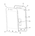
도 1은 본 발명과 관련된 이동 단말기의 일 예를 전면에서 바라본 사시도이다.1 is a front perspective view of an example of a mobile terminal according to the present invention;
개시된 이동 단말기(100)는 바(bar) 형태(도 2 내지 도 5참조)의 단말기 바디를 구비하고 있다. 다만, 본 발명은 여기에 한정되지 않고, 2 이상의 바디들이 상대 이동 가능하게 결합되는 슬라이드 타입, 폴더 타입(도 6참조), 스윙 타입, 스위블 타입 등 다양한 구조에 적용이 가능하다. The disclosed
바디는 외관을 이루는 케이스(케이싱, 하우징, 커버 등)를 포함한다. 본 실시예에서, 케이스는 프론트 케이스(101)와 리어 케이스(102)로 구분될 수 있다. 프론트 케이스(101)와 리어 케이스(102)의 사이에 형성된 공간에는 각종 전자부품들이 내장된다. 프론트 케이스(101)와 리어 케이스(102) 사이에는 적어도 하나의 중간 케이스가 추가로 배치될 수도 있다.The body includes a case (a casing, a housing, a cover, and the like) which forms an appearance. In this embodiment, the case may be divided into a
케이스들은 합성수지를 사출하여 형성되거나 금속 재질, 예를 들어 스테인레스 스틸(STS) 또는 티타늄(Ti) 등과 같은 금속 재질을 갖도록 형성될 수도 있다.The cases may be formed by injecting synthetic resin or may be formed of a metal material, for example, a metal material such as stainless steel (STS) or titanium (Ti).
단말기 바디, 주로 프론트 케이스(101)에는 디스플레이부(151), 음향출력부(152), 카메라(121), 사용자 입력부(130/131,132), 마이크(122), 인터페이스(170) 등이 배치될 수 있다.The
디스플레이부(151)는 프론트 케이스(101)의 주면의 대부분을 차지한다. 디스플레이부(151)의 양단부 중 일 단부에 인접한 영역에는 음향출력부(151)와 카메라(121)가 배치되고, 다른 단부에 인접한 영역에는 사용자 입력부(131)와 마이크(122)가 배치된다. 사용자 입력부(132)와 인터페이스(170) 등은 프론트 케이스(101) 및 리어 케이스(102)의 측면들에 배치될 수 있다.The
사용자 입력부(130)는 이동 단말기(100)의 동작을 제어하기 위한 명령을 입력받기 위해 조작되는 것으로서, 복수의 조작 유닛들(131,132)을 포함할 수 있다. 조작 유닛들(131,132)은 조작부(manipulating portion)로도 통칭 될 수 있으며, 사용자가 촉각 적인 느낌을 가면서 조작하게 되는 방식(tactile manner)이라면 어떤 방식이든 채용될 수 있다.The user input unit 130 is operated to receive a command for controlling the operation of the
제1 또는 제2조작 유닛들(131, 132)에 의하여 입력되는 내용은 다양하게 설정될 수 있다. 예를 들어, 제1 조작 유닛(131)은 시작, 종료, 스크롤 등과 같은 명령을 입력받고, 제2 조작 유닛(132)은 음향출력부(152)에서 출력되는 음향의 크기 조절 또는 디스플레이부(151)의 터치 인식 모드로의 전환 등과 같은 명령을 입력받을 수 있다.The contents inputted by the first or
도 2는 도 1에 도시된 이동 단말기의 후면 사시도이다. FIG. 2 is a rear perspective view of the mobile terminal shown in FIG. 1.
도 2를 참조하면, 단말기 바디의 후면, 다시 말해서 리어 케이스(102)에는 카메라(121')가 추가로 장착될 수 있다. 카메라(121')는 카메라(121, 도 2 참조)와 실질적으로 반대되는 촬영 방향을 가지며, 카메라(121)와 서로 다른 화소를 가지는 카메라일 수 있다.Referring to FIG. 2, a
예를 들어, 카메라(121)는 화상 통화 등의 경우에 얼굴을 촬영하여 상대방에 전송함에 무리가 없도록 저 화소를 가지며, 카메라(121')는 일반적인 피사체를 촬영하고 바로 전송하지는 않는 경우가 많기에 고 화소를 가지는 것이 바람직하다. 카메라(121,121')는 회전 또는 팝업(pop-up) 가능하게 단말기 바디에 설치될 수도 있다.For example, the
카메라(121')에 인접하게는 플래쉬(123)와 거울(124)이 추가로 배치된다. 플래쉬(123)는 카메라(121')로 피사체를 촬영하는 경우에 피사체를 향해 빛을 비추게 된다. 거울(124)은 사용자가 카메라(121')를 이용하여 자신을 촬영(셀프 촬영)하고자 하는 경우에, 사용자 자신의 얼굴 등을 비춰볼 수 있게 한다.A
단말기 바디의 후면에는 음향 출력부(152')가 추가로 배치될 수도 있다. 음향 출력부(152')는 음향 출력부(152, 도 2 참조)와 함께 스테레오 기능을 구현할 수 있으며, 통화시 스피커폰 모드의 구현을 위하여 사용될 수도 있다.An acoustic output 152 'may be additionally disposed on the rear surface of the terminal body. The
단말기 바디의 측면에는 통화 등을 위한 안테나 외에 방송신호 수신용 안테나(124)가 추가적으로 배치될 수 있다. 방송수신모듈(111, 도 1 참조)의 일부를 이루는 안테나(124)는 단말기 바디에서 인출 가능하게 설치될 수 있다.In addition to the antenna for a call or the like, a broadcast
단말기 바디에는 이동 단말기(100)에 전원을 공급하기 위한 전원공급부(190)가 장착된다. 전원공급부(190)는 단말기 바디에 내장되거나, 단말기 바디의 외부에서 직접 탈착될 수 있게 구성될 수 있다.A
리어 케이스(102)에는 터치를 감지하기 위한 터치 패드(135)가 추가로 장착될 수 있다. 터치 패드(135) 또한 디스플레이부(151)와 마찬가지로 광 투과형으로 구성될 수 있다. 이 경우에, 디스플레이부(151)가 양면에서 시각 정보를 출력하도록 구성된다면, 터치 패드(135)를 통해서도 상기 시각 정보를 인지할 수 있게 된다. 상기 양면에 출력되는 정보는 상기 터치 패드(135)에 의해 모두 제어될 수도 있다. 이와 달리, 터치 패드(135)에는 디스플레이가 추가로 장착되어, 리어 케이스(102)에도 터치 스크린이 배치될 수도 있다.The
터치 패드(135)는 프론트 케이스(101)의 디스플레이부(151)와 상호 관련되어 작동한다. 터치 패드(135)는 디스플레이부(151)의 전방 또는 후방에 평행하게 배치될 수 있다. 이러한 터치 패드(135)는 디스플레이부(151)와 동일하거나 작은 크기를 가질 수 있다.The
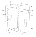
도 3은 본 발명의 일 실시예와 관련된 이동 단말기를 구성하는 디스플레이부와 프론트 케이스의 분리 사시도이고, 도 4는 본 발명의 일 실시예와 관련된 이동 단말기를 구성하는 디스플레이부와 프론트 케이스의 배면 분리 사시도이며, 도 5는 본 발명의 일 실시예와 관련된 이동 단말기를 구성하는 프론트 케이스의 정면도이다.3 is an exploded perspective view of a display unit and a front case constituting a mobile terminal according to an embodiment of the present invention, and FIG. 4 is a rear side separation of the display unit and the front case constituting a mobile terminal according to an embodiment of the present invention. 5 is a perspective view, and FIG. 5 is a front view of a front case constituting a mobile terminal according to an embodiment of the present invention.
또한, 도 6은 본 발명의 일 실시예와 관련된 이동 단말기를 구성하는 디스플레이부의 분리 사시도이고, 도 7 및 도 8은 본 발명의 일 실시예와 관련된 이동 단말기를 구성하는 프론트 케이스와 디스플레이부의 조립 상태를 설명하기 위한 단면도들이다.6 is an exploded perspective view of a display unit constituting a mobile terminal according to an embodiment of the present invention, and FIGS. 7 and 8 are assembled states of a front case and a display unit constituting a mobile terminal according to an embodiment of the present invention. It is sectional drawing for demonstrating this.
본 발명의 일 실시예와 관련된 이동 단말기(100)는 윈도우(210) 및 상기 윈도우(210)의 배면에 위치되고 하나 이상의 장착 리브(230)가 마련된 디스플레이 모듈(220)을 포함하는 디스플레이부(151)와 상기 디스플레이부(151)가 수용되며, 상기 장착리브(230)가 고정되는 삽입부(105)가 마련된 프론트 케이스(101)와 상기 프론트 케이스(101)의 후면에 결합되는 리어 케이스(102) 및 상기 리어 케이스(102)와 상기 프론트 케이스(101) 사이에 배치되며, 상기 디스플레이부(151)와 전기적으로 연결되는 제어부(180)를 포함한다.The
또한, 상기 삽입부(105)는 삽입홈일 수도 있고, 관통홀일 수도 있다.In addition, the
구체적으로, 본 발명의 일 실시예와 관련된 이동 단말기(100)는 전면에 리세스(103, 104)를 갖는 프론트 케이스(101)와 상기 리세스(103, 104)에 안착된 상태로 고정되고, 윈도우(210) 및 상기 윈도우(210)의 배면에 배치된 디스플레이 모듈(220)을 포함하는 디스플레이부(151)와 상기 프론트 케이스(101)의 후면에 결합되는 리어 케이스(102) 및 상기 리어 케이스(102)와 상기 프론트 케이스(101) 사이에 배치되며, 상기 디스플레이부(151)와 전기적으로 연결되는 제어부(180)를 포함할 수 있다.Specifically, the
도 3을 참조하면, 상기 디스플레이부(151)는 프론트 케이스(101)의 정면에서 조립될 수 있으며, 상기 프론트 케이스(101)의 전면에 형성된 리세스(103, 104)에 수용된 상태로 상기 프론트 케이스(101)에 고정될 수 있다.Referring to FIG. 3, the
도 4를 참조하면, 상기 프론트 케이스(101)에 형성되는 리세스(103, 104)는 상기 디스플레이부(151)의 윈도우(210)가 수용되는 제 1리세스(103)와 상기 제 1리세스(103) 내부에 마련되고 상기 디스플레이부(151)의 디스플레이 모듈(220)이 수용되는 제 2리세스(104)를 포함할 수 있다.Referring to FIG. 4, recesses 103 and 104 formed in the
제 1리세스(103)는 상기 디스플레이부(151)의 윈도우(210)의 면적 및 두께에 대응되는 크기 및 두께를 가질 수 있으며, 제 2리세스(104)는 상기 윈도우(210)의 배면에 배치된 디스플레이 모듈(220)의 면적 및 두께에 대응되는 면적 및 두께를 가질 수 있다.The
상기 디스플레이부(151)는 상기 윈도우(210)와 디스플레이 모듈(220)이 별도로 분리 배치되는 분리형 타입일 수도 있고, 상기 윈도우(210)의 배면에 상기 디스플레이 모듈(220)이 장착된 일체형 타입(하이브리드 타입)일 수도 있다.The
도 6을 참조하면, 상기 디스플레이부(151)는 윈도우(210)와 상기 윈도우(210)의 배면에 마련되는 투명 접착층(221)과 상기 투명 접착층(221, 예를 들어 SVR)을 매개로 윈도우(210)의 배면에 고정되는 디스플레이(222) 및 상기 디스플레이(222)를 둘러싸며 상기 윈도우(210)의 배면에 고정되는 커버 부재(223)를 포함할 수 있다.Referring to FIG. 6, the
상기 커버 부재(223)는 상기 디스플레이(222)를 보호하기 위하여 스테인레스 스틸(SUS) 등의 금속 재질로 형성될 수 있다. 또한, 상기 디스플레이(222)는 전술한 바와 같이, 액정 디스플레이(LCD), 유기 발광 다이오드(OLED) 또는 3차원 디스플레이일 수 있다.The
도 5를 참조하면, 상기 프론트 케이스(101)는 제 2리세스(104)의 바닥면 또는 일 측면에 형성된 하나 이상의 관통홀(105)을 가지고, 어느 한 리세스(103, 104)의 일 측에 형성된 개구부(104a)를 갖는다. 상기 관통홀(105)은 전술한 삽입부의 일예에 해당한다.Referring to FIG. 5, the
상기 관통홀(105)은 상기 디스플레이부(151)의 디스플레이 모듈(220)을 상기 프론트 케이스에 고정시키기 위하여 사용될 수 있다.The through
또한, 상기 프론트 케이스(101)는 전술한 바와 같이 수지 재질 또는 금속 재질로 형성될 수 있으며, 상기 디스플레이 모듈(220)의 하중을 지지하기 위하여 제 2리세스(104)는 금속 재질로 형성될 수 있다.In addition, the
일 실시태양으로, 상기 프론트 케이스(101)의 외주연은 수지 재질로 형성되고, 상기 리세스(예를 들어, 제 2리세스(104))는 마그네슘(Mg)으로 상기 프론트 케이스(101)의 외주연과 인서트 사출될 수 있다.In one embodiment, the outer periphery of the
따라서, 금속 재질의 제 2리세스(104)가 얇은 두께를 가지므로, 본 발명의 일 실시예와 관련된 이동 단말기(100)는 슬림한 디자인을 가질 수 있으며, 디스플레이 모듈(220)의 하중을 지지할 수 있는 충분한 강성을 가질 수 있다.Therefore, since the
도 4 및 도 5를 참조하면, 상기 개구부(104a)로는 상기 디스플레이부(151)와 제어부(180)를 전기적으로 연결하는 케이블이 통과될 수 있다. 한편, 미설명 부호 240은 디스플레이부(151)와 전기적으로 연결된 커넥터를 나타내며, 상기 케이블은 플렉서블 인쇄회로기판(FPCB)일 수 있다.4 and 5, a cable for electrically connecting the
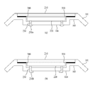
도 7 및 도 8을 참조하면, 상기 디스플레이부(151)의 윈도우(210)의 에지부와 상기 제 1리세스(103)의 바닥면은 접착될 수 있으며, 일 실시태양으로 양면 테이프(300)가 사용될 수 있다.7 and 8, an edge portion of the
한편, 상기 윈도우(210)의 에지부가 양면 테이프(300)를 통해 제 1리세스(103)의 바닥면에 접착되면, 외부 충격을 받았을 경우나 고온 고습한 환경에서는 상기 양면 테이프(300)의 접착력만으로 윈도우(210)와 디스플레이 모듈(220)의 하중을 견디지 못할 수 있다.On the other hand, when the edge portion of the
따라서, 상기 디스플레이 모듈(220)은 제 2리세스(104)의 바닥면 또는 적어도 하나 이상의 측면에 고정될 수 있다.Accordingly, the
전술한 바와 같이, 상기 디스플레이 모듈(220)은 금속 재질의 커버 부재(223)를 포함할 수 있으며, 상기 커버 부재(223)에는 하나 이상의 장착 리브(230)가 마련될 수 있다.As described above, the
도 5, 도 7의 (a) 및 도 9의 (a)를 참조하면, 상기 디스플레이 모듈(220)에는 하나 이상의 장착 리브(230)가 마련되고, 상기 프론트 케이스(101)의 제 2리세스(104)에는 상기 장착 리브(230)가 수용되는 삽입홈(105)이 마련될 수 있다. 또한, 상기 삽입홈(105)은 상기 프론트 케이스(101)의 제 2리세스(104)를 관통하는 관통홀일 수 있다.5, 7 (a) and 9 (a), the
구체적으로, 상기 제 2리세스(104)에는 상기 디스플레이 모듈(220)의 장착 리브(230)가 관통하는 관통홀(105)이 형성되며, 상기 관통홀(105)을 통과한 상기 장착 리브(230)의 자유 단부(230a) 중 적어도 하나 이상은 상기 제 2리세스(104)의 배면에 융착될 수 있다.Specifically, the
도 5에는 디스플레이 모듈(220)의 배면 각 에지부에 4개의 장착 리브(230)가 마련된 경우가 도시되어 있으나, 상기 장착 리브(230)의 갯수, 위치 등은 디자인적 특성 및 디스플레이 모듈(220)의 하중을 고려하여 다양하게 결정될 수 있다.FIG. 5 illustrates a case in which four mounting
한편, 4개의 장착 리브(230) 중 2개 이상의 장착 리브(230)만을 상기 제 2리세스(104)의 배면에 융착시킬 수 있다.Meanwhile, only two or more mounting
대각선 방향의 한 쌍의 장착 리브(230)를 상기 제 2리세스(104)의 배면에 융착시키는 경우에 수리 또는 디스플레이 모듈(220) 교체시에는 융착된 장착 리브(230)의 자유 단부(230a)를 제거하고 디스플레이 모듈(220)을 분리시킬 수 있으며, 조립 시에는 다른 대각선 방향의 한 쌍의 장착 리브(230)를 상기 제 2리세스(104)의 배면에 융착시킬 수 있다.
이와는 다르게, 도 7의 (b) 및 도 8의 (b)를 참조하면, 상기 제 2리세스(104)에는 상기 장착 리브(230)가 관통하는 관통홀(105)이 형성되며, 상기 관통홀(104)을 통과한 상기 장착 리브(230)의 자유 단부(230b) 중 적어도 하나 이상은 상기 제 2리세스(104)의 배면을 향하여 절곡될 수 있다.Unlike this, referring to FIGS. 7B and 8B, a through
또한, 대각선 방향의 한 쌍의 장착 리브(230)를 상기 제 2리세스(104)의 배면을 향하여 절곡시키는 경우에 수리 또는 디스플레이 모듈(220) 교체시에는 절곡된 장착 리브(230)의 자유 단부(230a)를 제거하거나 펼친 후 디스플레이 모듈(220)을 분리시킬 수 있으며, 조립 시에는 다른 대각선 방향의 한 쌍의 장착 리브(230)를 상기 제 2리세스(104)의 배면에 절곡시킬 수 있다.In addition, when the pair of mounting
따라서, 디스플레이부(151)의 디스플레이 모듈(220)을 상기 프론트 케이스(101)의 금속 재질의 제 2리세스(104)에 고정시킬 수 있으므로, 외부의 충격 또는 고온 고습 환경에서 프론트 케이스(101)의 전면을 통해 조립되는 디스플레이부(151)의 신뢰성을 확보할 수 있다.Accordingly, since the
상기와 같이 구성되는 본 발명의 적어도 하나의 실시예에 관련된 이동 단말기는 조립성을 향상시키고, 외부 충격에 의하여 디스플레이부가 분리되는 것을 방지하며, 신뢰성을 높일 수 있다.The mobile terminal according to at least one embodiment of the present invention configured as described above may improve assembly performance, prevent separation of the display unit by external impact, and increase reliability.
또한, 본 발명의 적어도 하나의 실시예에 관련된 이동 단말기는 수리 시 용이하게 디스플레이부가 분리 및 조립될 수 있다.In addition, the mobile terminal according to at least one embodiment of the present invention may be easily disassembled and assembled at the time of repair.
상기와 같이 설명된 이동 단말기는 상기 설명된 실시예들의 구성과 방법이 한정되게 적용될 수 있는 것이 아니라, 상기 실시예들은 다양한 변형이 이루어질 수 있도록 각 실시예들의 전부 또는 일부가 선택적으로 조합되어 구성될 수도 있다.The mobile terminal described above can be applied to not only the configuration and method of the embodiments described above but also all or some of the embodiments may be selectively combined so that various modifications may be made to the embodiments It is possible.
100: 이동 단말기 101: 프론트 케이스
102: 리어 케이스 103: 제 1리세스
104: 제 2리세스 105: 관통홀
151: 디스플레이부 180: 제어부
210: 윈도우 220: 디스플레이 모듈
230: 장착 리브 240: 커넥터
300: 양면 테이프100: mobile terminal 101: front case
102: rear case 103: first recess
104: second recess 105: through hole
151: display unit 180: control unit
210: window 220: display module
230: Mounting rib 240: Connector
300: double sided tape
Claims (8)
상기 디스플레이부가 수용되며, 상기 장착리브가 고정되는 삽입부가 마련된 프론트 케이스;
상기 프론트 케이스의 후면에 결합되는 리어 케이스; 및
상기 리어 케이스와 상기 프론트 케이스 사이에 배치되며, 상기 디스플레이부와 전기적으로 연결되는 제어부를 포함하는 이동 단말기.A display unit including a window and a display module disposed on a rear surface of the window and provided with at least one mounting rib;
A front case accommodating the display unit and having an insertion unit to which the mounting rib is fixed;
A rear case coupled to a rear surface of the front case; And
And a control unit disposed between the rear case and the front case and electrically connected to the display unit.
상기 프론트 케이스는 전면에 마련되며 상기 윈도우가 수용되는 제 1리세스 및 상기 제 1리세스 내부에 마련되고 상기 디스플레이 모듈이 수용되는 제 2리세스를 포함하는 것을 특징으로 하는 이동 단말기.The method of claim 1,
The front case includes a first recess provided in the front surface and a second recess provided in the first recess and a second recess provided in the first recess to accommodate the display module.
상기 윈도우의 에지부와 상기 제 1리세스의 바닥면은 접착되는 것을 특징으로 하는 이동 단말기.The method of claim 2,
The edge portion of the window and the bottom surface of the first recess is bonded.
디스플레이 모듈의 장착 리브는 제 2리세스의 바닥면 또는 적어도 하나 이상의 측면에 고정되는 것을 특징으로 하는 이동 단말기.The method according to claim 2 or 3,
The mounting rib of the display module is fixed to the bottom surface or at least one side of the second recess.
상기 제 2리세스에는 상기 장착 리브가 관통하는 관통홀이 형성되며,
상기 관통홀을 통과한 상기 장착 리브의 자유 단부 중 적어도 하나 이상은 상기 제 2리세스의 배면에 융착되는 것을 특징으로 하는 이동 단말기.The method of claim 4, wherein
The second recess has a through hole through which the mounting rib penetrates.
And at least one of the free ends of the mounting ribs passing through the through-holes is fused to the rear surface of the second recess.
상기 제 2리세스에는 상기 장착 리브가 관통하는 관통홀이 형성되며,
상기 관통홀을 통과한 상기 장착 리브의 자유 단부 중 적어도 하나 이상은 상기 제 2리세스의 배면을 향하여 절곡된 것을 특징으로 하는 이동 단말기.The method of claim 4, wherein
The second recess has a through hole through which the mounting rib penetrates.
And at least one of the free ends of the mounting ribs passing through the through holes is bent toward the rear surface of the second recess.
상기 프론트 케이스의 제 2리세스는 금속 재질로 형성되는 것을 특징으로 하는 이동 단말기.The method of claim 2,
The second recess of the front case is formed of a metallic material.
상기 프론트 케이스의 외주연 및 제 1리세스는 수지 재질로 형성되고, 상기 제 2리세스는 마그네슘으로 상기 프론트 케이스의 외주연과 인서트 사출되는 것을 특징으로 하는 이동 단말기.The method of claim 7, wherein
The outer periphery and the first recess of the front case is formed of a resin material, and the second recess is a mobile terminal, characterized in that the outer periphery of the front case and the insert is injected into magnesium.
Priority Applications (1)
| Application Number | Priority Date | Filing Date | Title |
|---|---|---|---|
| KR1020110034185A KR101804915B1 (en) | 2011-04-13 | 2011-04-13 | Mobile terminal |
Applications Claiming Priority (1)
| Application Number | Priority Date | Filing Date | Title |
|---|---|---|---|
| KR1020110034185A KR101804915B1 (en) | 2011-04-13 | 2011-04-13 | Mobile terminal |
Publications (2)
| Publication Number | Publication Date |
|---|---|
| KR20120116632A true KR20120116632A (en) | 2012-10-23 |
| KR101804915B1 KR101804915B1 (en) | 2017-12-05 |
Family
ID=47284848
Family Applications (1)
| Application Number | Title | Priority Date | Filing Date |
|---|---|---|---|
| KR1020110034185A Expired - Fee Related KR101804915B1 (en) | 2011-04-13 | 2011-04-13 | Mobile terminal |
Country Status (1)
| Country | Link |
|---|---|
| KR (1) | KR101804915B1 (en) |
Cited By (1)
| Publication number | Priority date | Publication date | Assignee | Title |
|---|---|---|---|---|
| US9483078B2 (en) | 2013-04-17 | 2016-11-01 | Lg Electronics Inc. | Mobile terminal |
Family Cites Families (2)
| Publication number | Priority date | Publication date | Assignee | Title |
|---|---|---|---|---|
| JP2002330199A (en) * | 2001-04-26 | 2002-11-15 | Kyocera Corp | Portable information terminal and method for manufacturing portable information terminal |
| JP5374987B2 (en) | 2008-09-17 | 2013-12-25 | 富士通株式会社 | Mobile terminal device |
-
2011
- 2011-04-13 KR KR1020110034185A patent/KR101804915B1/en not_active Expired - Fee Related
Cited By (1)
| Publication number | Priority date | Publication date | Assignee | Title |
|---|---|---|---|---|
| US9483078B2 (en) | 2013-04-17 | 2016-11-01 | Lg Electronics Inc. | Mobile terminal |
Also Published As
| Publication number | Publication date |
|---|---|
| KR101804915B1 (en) | 2017-12-05 |
Similar Documents
| Publication | Publication Date | Title |
|---|---|---|
| US9086846B2 (en) | Mobile terminal | |
| EP2015565B1 (en) | Portable communications terminal having camera assembly with two cameras | |
| KR102468709B1 (en) | Key module and mobile terminal having the same, and method for assembling the key module | |
| US8880129B2 (en) | Mobile terminal | |
| KR101437966B1 (en) | Mobile terminal | |
| KR101186530B1 (en) | Electronic device and controling method thereof | |
| KR20120120661A (en) | Flexible printed circuit board and mobile terminal using it | |
| KR101810463B1 (en) | Mobile terminal | |
| KR101592113B1 (en) | Mobile terminal | |
| KR101271540B1 (en) | Mobile terminal | |
| KR101976464B1 (en) | Mobile terminal and apparatus for molding a battery equipped therein | |
| KR101804915B1 (en) | Mobile terminal | |
| KR101918989B1 (en) | Mobile terminal | |
| KR101984578B1 (en) | Mobile terminal | |
| KR101919774B1 (en) | Mobile Terminal | |
| KR101850387B1 (en) | Mobile terminal | |
| KR101960513B1 (en) | Mobile terminal | |
| KR102018374B1 (en) | Mobile terminal | |
| KR101667429B1 (en) | Portable electronic apparatus | |
| KR101969899B1 (en) | Mobile terminal | |
| KR101257092B1 (en) | Mobile terminal | |
| KR101980708B1 (en) | Mobile terminal | |
| KR101981315B1 (en) | Mobile terminal | |
| KR101789536B1 (en) | Mobile terminal | |
| KR20130049090A (en) | Mobile terminal |
Legal Events
| Date | Code | Title | Description |
|---|---|---|---|
| PA0109 | Patent application |
St.27 status event code: A-0-1-A10-A12-nap-PA0109 |
|
| PG1501 | Laying open of application |
St.27 status event code: A-1-1-Q10-Q12-nap-PG1501 |
|
| R17-X000 | Change to representative recorded |
St.27 status event code: A-3-3-R10-R17-oth-X000 |
|
| PN2301 | Change of applicant |
St.27 status event code: A-3-3-R10-R13-asn-PN2301 St.27 status event code: A-3-3-R10-R11-asn-PN2301 |
|
| A201 | Request for examination | ||
| PA0201 | Request for examination |
St.27 status event code: A-1-2-D10-D11-exm-PA0201 |
|
| P22-X000 | Classification modified |
St.27 status event code: A-2-2-P10-P22-nap-X000 |
|
| P22-X000 | Classification modified |
St.27 status event code: A-2-2-P10-P22-nap-X000 |
|
| D13-X000 | Search requested |
St.27 status event code: A-1-2-D10-D13-srh-X000 |
|
| D14-X000 | Search report completed |
St.27 status event code: A-1-2-D10-D14-srh-X000 |
|
| E902 | Notification of reason for refusal | ||
| PE0902 | Notice of grounds for rejection |
St.27 status event code: A-1-2-D10-D21-exm-PE0902 |
|
| E13-X000 | Pre-grant limitation requested |
St.27 status event code: A-2-3-E10-E13-lim-X000 |
|
| P11-X000 | Amendment of application requested |
St.27 status event code: A-2-2-P10-P11-nap-X000 |
|
| P13-X000 | Application amended |
St.27 status event code: A-2-2-P10-P13-nap-X000 |
|
| E701 | Decision to grant or registration of patent right | ||
| PE0701 | Decision of registration |
St.27 status event code: A-1-2-D10-D22-exm-PE0701 |
|
| GRNT | Written decision to grant | ||
| PR0701 | Registration of establishment |
St.27 status event code: A-2-4-F10-F11-exm-PR0701 |
|
| PR1002 | Payment of registration fee |
St.27 status event code: A-2-2-U10-U11-oth-PR1002 Fee payment year number: 1 |
|
| PG1601 | Publication of registration |
St.27 status event code: A-4-4-Q10-Q13-nap-PG1601 |
|
| PN2301 | Change of applicant |
St.27 status event code: A-5-5-R10-R13-asn-PN2301 St.27 status event code: A-5-5-R10-R11-asn-PN2301 |
|
| LAPS | Lapse due to unpaid annual fee | ||
| PC1903 | Unpaid annual fee |
St.27 status event code: A-4-4-U10-U13-oth-PC1903 Not in force date: 20201130 Payment event data comment text: Termination Category : DEFAULT_OF_REGISTRATION_FEE |
|
| PC1903 | Unpaid annual fee |
St.27 status event code: N-4-6-H10-H13-oth-PC1903 Ip right cessation event data comment text: Termination Category : DEFAULT_OF_REGISTRATION_FEE Not in force date: 20201130 |