KR20120115361A - Wind-powered electrical generator - Google Patents
Wind-powered electrical generator Download PDFInfo
- Publication number
- KR20120115361A KR20120115361A KR1020127020622A KR20127020622A KR20120115361A KR 20120115361 A KR20120115361 A KR 20120115361A KR 1020127020622 A KR1020127020622 A KR 1020127020622A KR 20127020622 A KR20127020622 A KR 20127020622A KR 20120115361 A KR20120115361 A KR 20120115361A
- Authority
- KR
- South Korea
- Prior art keywords
- tower
- opening
- opening area
- outer box
- pressure loss
- Prior art date
Links
Images


Classifications
-
- F—MECHANICAL ENGINEERING; LIGHTING; HEATING; WEAPONS; BLASTING
- F03—MACHINES OR ENGINES FOR LIQUIDS; WIND, SPRING, OR WEIGHT MOTORS; PRODUCING MECHANICAL POWER OR A REACTIVE PROPULSIVE THRUST, NOT OTHERWISE PROVIDED FOR
- F03D—WIND MOTORS
- F03D80/00—Details, components or accessories not provided for in groups F03D1/00 - F03D17/00
-
- F—MECHANICAL ENGINEERING; LIGHTING; HEATING; WEAPONS; BLASTING
- F03—MACHINES OR ENGINES FOR LIQUIDS; WIND, SPRING, OR WEIGHT MOTORS; PRODUCING MECHANICAL POWER OR A REACTIVE PROPULSIVE THRUST, NOT OTHERWISE PROVIDED FOR
- F03D—WIND MOTORS
- F03D13/00—Assembly, mounting or commissioning of wind motors; Arrangements specially adapted for transporting wind motor components
- F03D13/20—Arrangements for mounting or supporting wind motors; Masts or towers for wind motors
-
- F—MECHANICAL ENGINEERING; LIGHTING; HEATING; WEAPONS; BLASTING
- F03—MACHINES OR ENGINES FOR LIQUIDS; WIND, SPRING, OR WEIGHT MOTORS; PRODUCING MECHANICAL POWER OR A REACTIVE PROPULSIVE THRUST, NOT OTHERWISE PROVIDED FOR
- F03D—WIND MOTORS
- F03D80/00—Details, components or accessories not provided for in groups F03D1/00 - F03D17/00
- F03D80/60—Cooling or heating of wind motors
-
- F—MECHANICAL ENGINEERING; LIGHTING; HEATING; WEAPONS; BLASTING
- F03—MACHINES OR ENGINES FOR LIQUIDS; WIND, SPRING, OR WEIGHT MOTORS; PRODUCING MECHANICAL POWER OR A REACTIVE PROPULSIVE THRUST, NOT OTHERWISE PROVIDED FOR
- F03D—WIND MOTORS
- F03D9/00—Adaptations of wind motors for special use; Combinations of wind motors with apparatus driven thereby; Wind motors specially adapted for installation in particular locations
- F03D9/20—Wind motors characterised by the driven apparatus
- F03D9/25—Wind motors characterised by the driven apparatus the apparatus being an electrical generator
-
- F—MECHANICAL ENGINEERING; LIGHTING; HEATING; WEAPONS; BLASTING
- F05—INDEXING SCHEMES RELATING TO ENGINES OR PUMPS IN VARIOUS SUBCLASSES OF CLASSES F01-F04
- F05B—INDEXING SCHEME RELATING TO WIND, SPRING, WEIGHT, INERTIA OR LIKE MOTORS, TO MACHINES OR ENGINES FOR LIQUIDS COVERED BY SUBCLASSES F03B, F03D AND F03G
- F05B2240/00—Components
- F05B2240/90—Mounting on supporting structures or systems
- F05B2240/91—Mounting on supporting structures or systems on a stationary structure
- F05B2240/912—Mounting on supporting structures or systems on a stationary structure on a tower
-
- F—MECHANICAL ENGINEERING; LIGHTING; HEATING; WEAPONS; BLASTING
- F05—INDEXING SCHEMES RELATING TO ENGINES OR PUMPS IN VARIOUS SUBCLASSES OF CLASSES F01-F04
- F05B—INDEXING SCHEME RELATING TO WIND, SPRING, WEIGHT, INERTIA OR LIKE MOTORS, TO MACHINES OR ENGINES FOR LIQUIDS COVERED BY SUBCLASSES F03B, F03D AND F03G
- F05B2260/00—Function
- F05B2260/20—Heat transfer, e.g. cooling
-
- F—MECHANICAL ENGINEERING; LIGHTING; HEATING; WEAPONS; BLASTING
- F05—INDEXING SCHEMES RELATING TO ENGINES OR PUMPS IN VARIOUS SUBCLASSES OF CLASSES F01-F04
- F05B—INDEXING SCHEME RELATING TO WIND, SPRING, WEIGHT, INERTIA OR LIKE MOTORS, TO MACHINES OR ENGINES FOR LIQUIDS COVERED BY SUBCLASSES F03B, F03D AND F03G
- F05B2260/00—Function
- F05B2260/60—Fluid transfer
- F05B2260/64—Aeration, ventilation, dehumidification or moisture removal of closed spaces
-
- Y—GENERAL TAGGING OF NEW TECHNOLOGICAL DEVELOPMENTS; GENERAL TAGGING OF CROSS-SECTIONAL TECHNOLOGIES SPANNING OVER SEVERAL SECTIONS OF THE IPC; TECHNICAL SUBJECTS COVERED BY FORMER USPC CROSS-REFERENCE ART COLLECTIONS [XRACs] AND DIGESTS
- Y02—TECHNOLOGIES OR APPLICATIONS FOR MITIGATION OR ADAPTATION AGAINST CLIMATE CHANGE
- Y02E—REDUCTION OF GREENHOUSE GAS [GHG] EMISSIONS, RELATED TO ENERGY GENERATION, TRANSMISSION OR DISTRIBUTION
- Y02E10/00—Energy generation through renewable energy sources
- Y02E10/70—Wind energy
- Y02E10/72—Wind turbines with rotation axis in wind direction
-
- Y—GENERAL TAGGING OF NEW TECHNOLOGICAL DEVELOPMENTS; GENERAL TAGGING OF CROSS-SECTIONAL TECHNOLOGIES SPANNING OVER SEVERAL SECTIONS OF THE IPC; TECHNICAL SUBJECTS COVERED BY FORMER USPC CROSS-REFERENCE ART COLLECTIONS [XRACs] AND DIGESTS
- Y02—TECHNOLOGIES OR APPLICATIONS FOR MITIGATION OR ADAPTATION AGAINST CLIMATE CHANGE
- Y02E—REDUCTION OF GREENHOUSE GAS [GHG] EMISSIONS, RELATED TO ENERGY GENERATION, TRANSMISSION OR DISTRIBUTION
- Y02E10/00—Energy generation through renewable energy sources
- Y02E10/70—Wind energy
- Y02E10/728—Onshore wind turbines
Abstract
타워 강도를 확보하면서 흡배기용 큰 개구 면적을 확보하고, 충분한 냉각 성능을 갖는 풍력 발전 장치를 제공한다. 풍차 날개에 풍력을 받아서 회전하는 로터 헤드가 너셀의 내부에 설치된 발전기를 구동해서 발전하고, 너셀이 기초 위에 세워 설치된 타워(2)의 상단부에 설치되는 동시에, 타워(2)의 표면에 설치한 타워 개구(20)로부터 타워 내부에 외기를 도입해서 내부 공간을 냉각하는 풍력 발전 장치에 있어서, 타워 개구(20)로부터 타워 내측으로 연장하는 오목부의 통형상부(21)를 갖고, 통형상부(21)를 구성하는 면의 일부 또는 전부에 설치된 압력 손실 요소를 거쳐서 통기 가능하게 구성되는 동시에, 압력 손실 요소를 설치한 유효 개구 면적을 타워 개구(20)의 실개구 면적보다도 크게 하였다.The present invention provides a wind power generator having a large opening area for an intake and exhaust gas while securing tower strength and having sufficient cooling performance. The rotor head, which receives and rotates wind power on the windmill blades, generates power by driving a generator installed in the interior of the nussel, and the nussel is installed on the upper end of the tower 2 installed on the foundation and installed on the surface of the tower 2. In the wind turbine generator which introduces outside air into the tower from the opening 20 and cools the internal space, the tubular portion 21 has a tubular portion 21 of a concave portion extending from the tower opening 20 to the inside of the tower. In addition, the effective opening area provided with the pressure loss element was made larger than the actual opening area of the tower opening 20 while being able to be ventilated through the pressure loss element provided in one part or all part of the surface which constitutes).
Description
본 발명은, 운전 시의 기기 손실에 의한 발열을 외기의 도입에 의해 냉각하는 풍력 발전 장치에 관한 것으로, 특히 외기를 도입하는 개구가 타워에 설치되어 있는 풍력 발전 장치에 관한 것이다.BACKGROUND OF THE
풍력 발전 장치(이하에서는, 「풍차」라고도 함)는, 풍차 날개를 구비한 로터 헤드가 풍력을 받아서 회전하고, 이 회전을 증속기에 의해 증속하는 등으로 해서 구동되는 발전기에 의해 발전하는 장치이다.The wind power generator (hereinafter also referred to as "windmill") is a device that is generated by a generator driven by a rotor head provided with windmill blades receiving wind and rotating the wind, and increasing the rotation by a speed increaser.
상술한 로터 헤드는, 풍차용 타워(이하, 「타워」라고 함) 위에 설치되어 요 선회 가능한 너셀의 단부에 장착되고, 대략 수평한 횡방향의 회전축선 주위로 회전 가능해지도록 지지되어 있다.The above-mentioned rotor head is mounted on the windmill tower (hereinafter referred to as "tower") and is attached to an end portion of the retractable nussel, and is supported to be rotatable around an approximately horizontal horizontal axis of rotation.
일반적으로, 상술한 풍차용 타워는, 원통형상의 쉘을 사용한 강제 모노폴식을 채용하는 경우가 많으며, 타워 쉘의 하단부에 설치한 베이스 플레이트를 철근 콘크리트의 기초에 앵커 볼트로 고정하는 구조로 되어 있다.Generally, the above-mentioned windmill tower employ | adopts the forced monopole type using a cylindrical shell, and has a structure which fixes the base plate provided in the lower end of a tower shell to the base of reinforced concrete with anchor bolt.
이러한 풍력 발전 장치는, 컨버터 등의 전기 기기를 구비하고 있으므로, 안정된 운전을 계속하기 위해서는, 발열체인 전기 기기 등을 냉각할 필요가 있다. 즉, 풍력 발전 장치는 운전에 수반하는 기기 손실의 발열이 발생하므로, 기기류의 온도 상승을 소정값 이내로 억제하기 위해서는 적절한 냉각이 필요해진다.Since such a wind turbine is provided with electrical equipment, such as a converter, in order to continue stable operation, it is necessary to cool the electrical equipment etc. which are heating elements. That is, since the wind power generator generates heat of equipment loss accompanying operation, appropriate cooling is necessary in order to suppress the temperature rise of equipment within a predetermined value.
도 18에 도시하는 종래예는, 타워 개구부로부터 외기를 도입하고, 이 외기에 의해 풍력 발전 장치의 기기 손실에 수반하는 발열을 냉각하는 냉각 구조의 개념도이다. 도면에 있어서, 참조부호 1은 풍력 발전 장치, 참조부호 2는 타워, 참조부호 3은 너셀, 참조부호 4는 로터 헤드, 참조부호 10은 도어용 개구부이며, 도면 중 화살표는 외기의 흐름을 나타내고 있다.The prior art example shown in FIG. 18 is a conceptual diagram of the cooling structure which introduces external air from the tower opening and cools the heat generated by equipment loss of the wind turbine by this outdoor air. In the drawings,
이 경우, 전기 기기 등의 냉각 대상은 너셀(3) 내에 설치된 너셀 내 기기(3a)이며, 환기 팬(3b)을 운전해서 도어용 개구부(10)의 적소에 설치한 흡기구(도시하지 않음)로부터 타워(2)의 내부에 외기를 도입하고, 이 외기가 너셀(3)의 내부를 통과해서 환기 및 냉각을 한다. 또한, 너셀 내 기기(3a)를 냉각한 외기는, 환기 팬(3b)으로부터 대기로 배출된다.In this case, the object to be cooled, such as an electric device, is a
또한, 너셀 내 기기(3a)의 냉각 구조로서는, 너셀(3) 내를 순환하는 외기에 의해 직접 냉각하는 구조 외에, 너셀 내 기기(3a) 및 냉각용 열 교환기를 순환하는 냉매(물이나 오일 등)를 사용하고, 냉매용 열 교환기에서 외기에 흡열된 냉매에 의해 간접적으로 냉각하는 구조, 그리고 직접 및 간접 냉각을 병용해서 냉각하는 구조가 있다.In addition, as a cooling structure of the
이 외에도, 종래의 풍력 발전 장치에 있어서는, 전기 기기 등의 발열체를 냉각하기 위해서, 예를 들어 냉각 매체를 순환시켜서 냉각하는 냉각 장치로서, 타워의 외부에 설치한 열 교환기를 구비한 것이 있다. 이 경우, 타워 외부의 열 교환기에 도입한 냉각 매체는, 열 교환기를 통과하는 외기와의 열 교환에 의해 냉각된다.(예를 들어, 특허 문헌 1 참조)In addition, in the conventional wind turbine generator, in order to cool heating elements, such as an electric device, there exist some which provided the heat exchanger provided in the exterior of the tower as a cooling apparatus which circulates and cools a cooling medium, for example. In this case, the cooling medium introduced into the heat exchanger outside the tower is cooled by heat exchange with outside air passing through the heat exchanger. (See
그런데, 풍력 발전 장치의 타워 내에 외기를 도입해서 냉각하는 경우, 타워 내에 외기를 도입하기 위해서는, 타워의 표면에 흡배기구가 되는 개구부를 설치하는 것이 필요해진다. 이러한 흡배기구에는, 공기 중의 액적, 먼지 및 염분 등을 제거하기 위해서, 환기용소창, 필터, 제염 필터 등의 압력 손실 요소가 설치되어 있다.By the way, when the outside air is introduced into the tower of the wind turbine and cooled, it is necessary to provide an opening that serves as an intake and exhaust mechanism on the surface of the tower in order to introduce the outside air into the tower. In order to remove liquid droplets, dust, salt, and the like in the air, pressure intake elements such as a ventilation window, a filter, and a decontamination filter are provided in the intake and exhaust mechanism.
이 때문에, 타워 강도를 확보하기 위해서 개구를 작게 설정하면, 개구를 통과할 때의 유속이 증가하므로, 압력 손실 요소에 있어서의 압력 손실(유속의 2승에 비례)이 커진다. 따라서, 자연 환기하는 경우에는, 충분한 환기 풍량의 확보가 곤란해져, 결과적으로는 타워 내부의 온도가 상승한다고 하는 문제를 갖고 있다.For this reason, when the opening is set small to secure the tower strength, the flow velocity when passing through the opening increases, so that the pressure loss (proportional to the square of the flow rate) of the pressure loss element is increased. Therefore, in the case of natural ventilation, it is difficult to secure a sufficient amount of ventilation airflow, resulting in a problem that the temperature inside the tower rises.
또한, 환기 팬에 의해 강제 환기하는 경우에는, 압력 손실이 크기 때문에 사용하는 팬의 동력도 커지고, 결과적으로 소내 동력을 소비하게 되어 바람직하지 못하다.In the case of forced ventilation by the ventilation fan, since the pressure loss is large, the power of the fan to be used also increases, and consequently the internal power is consumed, which is not preferable.
더구나, 타워의 개구 면적에 반해, 냉각 및 타워 강도는 트레이드 오프의 관계로 되어 있는데, 풍차 출력의 증가량에 반해 타워 직경의 증가량은 매우 작은 것으로 된다. 즉, 최근 풍차 대형화(출력 증가)에 수반하여, 기기 손실(발열량)이 증가해서 필요해지는 냉각 공기 유량도 증대하고 있으므로, 그 만큼 큰 증가를 바랄 수 없는 타워 직경에 반해, 타워 강도를 확보하면서 흡배기구에 큰 개구 면적을 확보하는 것은 곤란해진다. 따라서, 상술한 냉각 및 타워 강도에 있어서의 트레이드 오프의 관계는, 풍력 발전 장치가 대형화할수록 매우 어려워진다.Furthermore, in contrast to the opening area of the tower, cooling and tower strength are traded off, whereas the increase in tower diameter is very small, compared to the increase in windmill output. In other words, with the increase in windmill size (increase in output), the amount of cooling air required due to an increase in equipment loss (heat generation) is also increasing. It is difficult to ensure a large opening area in the sphere. Therefore, the relationship between the above-mentioned cooling and the trade-off in tower strength becomes very difficult as the wind turbine is enlarged.
본 발명은, 상기 사정을 감안하여 이루어진 것으로, 그 목적으로 하는 바는, 타워 강도를 확보하면서 흡배기용 큰 개구 면적을 확보하여, 충분한 냉각 성능을 갖는 풍력 발전 장치를 제공하는 데 있다.This invention is made | formed in view of the said situation, Comprising: It aims at providing the wind power generator which ensures the large opening area for intake and exhaust air while ensuring tower strength, and has sufficient cooling performance.
본 발명은, 상기 과제를 해결하기 위해서, 하기의 수단을 채용하였다.MEANS TO SOLVE THE PROBLEM In order to solve the said subject, this invention employ | adopted the following means.
본 발명에 따른 풍력 발전 장치는, 풍차 날개에 풍력을 받아서 회전하는 로터 헤드가 너셀의 내부에 설치된 발전기를 구동해서 발전하고, 상기 너셀이 기초 위에 세워 설치된 타워의 상단부에 설치되는 동시에, 상기 타워의 표면에 설치한 타워 개구로부터 타워 내부에 외기를 도입해서 내부 공간을 냉각하는 풍력 발전 장치에 있어서, 상기 타워 개구로부터 타워 내측으로 연장하는 오목부 또는 상기 타워 개구로부터 타워 외측으로 연장하는 볼록부를 갖고, 상기 오목부 또는 상기 볼록부를 구성하는 면의 일부 또는 전부에 설치된 압력 손실 요소를 거쳐서 통기 가능하게 구성되는 동시에, 상기 압력 손실 요소를 설치한 유효 개구 면적이 상기 타워 개구의 실개구 면적보다도 큰 것을 특징으로 하는 것이다.In the wind power generation device according to the present invention, a rotor head which receives and rotates wind power on a windmill blade drives power generators installed inside a nussel, and is installed at an upper end of a tower in which the nussel is built on a foundation. In the wind turbine generator which introduces outside air into the tower interior from the tower opening provided in the surface, and cools an internal space, It has a concave part extended from the said tower opening to the inside of a tower, or a convex part extending from the tower opening to the outside of a tower, It is comprised so that ventilation is possible through the pressure loss element provided in part or all of the surface which comprises the said recessed part or the said convex part, and the effective opening area which provided the said pressure loss element is larger than the actual opening area of the said tower opening. It is to be done.
이러한 풍력 발전 장치는, 타워 개구로부터 타워 내측으로 연장하는 오목부 또는 타워 개구로부터 타워 외측으로 연장하는 볼록부를 갖고, 오목부 또는 볼록부를 구성하는 면의 일부 또는 전부에 설치된 압력 손실 요소를 거쳐서 통기 가능하게 구성되는 동시에, 압력 손실 요소를 설치한 유효 개구 면적이 타워 개구의 실개구 면적보다도 크므로, 타워 개구를 최소한으로 억제해서 타워 강도를 확보하는 동시에, 큰 유효 개구 면적에 설치한 압력 손실 요소를 통과하는 외기의 유속을 작게 할 수 있다. 특히, 타워 개구로부터 타워 내측으로 연장하는 오목부는, 압력 손실 요소를 설치하는 장소가 타워 외면으로부터 깊숙한 위치가 되기 때문에, 분진이나 빗물 등의 이물질은 압력 손실 요소까지 도달하기 어려운 구조가 된다.Such a wind power generator has a recess extending from the tower opening to the inside of the tower or a convex extending from the tower opening to the outside of the tower, and can be vented through a pressure loss element provided on part or all of the surface constituting the recess or the protrusion. In addition, since the effective opening area provided with the pressure loss element is larger than the actual opening area of the tower opening, the tower opening can be minimized to secure the tower strength and the pressure loss element provided in the large effective opening area The flow velocity of outside air passing through can be made small. In particular, the concave portion extending from the tower opening to the inside of the tower has a position where the pressure loss element is provided deep from the tower outer surface, so that foreign matters such as dust and rainwater cannot reach the pressure loss element.
또한, 본 발명에 있어서의 오목부 또는 볼록부는, 원형의 단면이나 직사각형 단면의 통모양형이나, 내부가 중공의 상자형이나 계단모양상자형 등을 포함한다.Moreover, the recessed part or convex part in this invention includes the cylindrical shape of circular cross section or rectangular cross section, the hollow box shape, the stepped box shape, etc. inside.
상기 발명에 있어서, 상기 타워 개구는, 타워 내부에 출입하기 위한 도어를 설치하는 도어용 개구부 중 적어도 일부가 이용되는 것이 바람직하다. 이에 의해, 타워에 반드시 필요로 되는 도어용 개구부를 유효하게 이용하고, 타워 개구의 실개구 면적보다 큰 유효 개구 면적을 용이하게 형성할 수 있다.In the above invention, it is preferable that at least a part of the door opening for installing the door for entering and exiting the tower is used as the tower opening. Thereby, the opening part for doors essential to a tower can be utilized effectively, and the effective opening area larger than the actual opening area of a tower opening can be formed easily.
상기 발명에 있어서, 상기 오목부 또는 상기 볼록부는, 그 구성면 중 어느 하나의 위치에 개폐 가능하는 출입구를 구비한 것이 바람직하다.In the said invention, it is preferable that the said recessed part or the said convex part is provided with the doorway which can be opened and closed in any one position of the structure surface.
상기 발명에 있어서, 상기 오목부 또는 상기 볼록부는, 상기 타워 개구로부터 끝으로 갈수록 넓어지게 형성되어 있는 것이 바람직하다. 이에 의해, 큰 유효 개구 면적의 확보가 용이해진다.In the above invention, it is preferable that the concave portion or the convex portion is formed to become wider from the tower opening toward the end. This facilitates securing a large effective opening area.
상기 오목부는, 상기 타워 개구로부터 타워축 중심 방향으로 상향으로 경사져 있는 것이 바람직하다. 이에 의해, 이물질(분진이나 빗물 등)은 압력 손실 요소까지 도달하기 어려워진다.It is preferable that the said recessed part inclines upward from the tower opening toward the tower axis center direction. As a result, foreign matter (dust, rain water, etc.) becomes difficult to reach the pressure loss element.
상기 발명에 있어서, 상기 오목부 또는 상기 볼록부의 단면형상이 직선부를 포함하고 있는 것이 바람직하다. 이에 의해, 덕트 등의 접속 및 설치가 용이해진다. 이 경우, 직선부를 포함하는 적합한 형상으로서는, 정사각형, 직사각형 및 대략 타원형 등이 있으며, 특히 개구부를 세로 길이의 형상으로 하면, 원형이나 정사각형의 각형상과 비교해서 타워 강도의 확보가 용이해진다.In the above invention, it is preferable that the cross-sectional shape of the concave portion or the convex portion includes a straight portion. Thereby, connection and installation of a duct etc. become easy. In this case, suitable shapes including a straight portion include squares, rectangles, and substantially elliptical shapes, and in particular, when the openings have a vertical length shape, the tower strength can be easily secured as compared with a circular or square square shape.
상기 발명에 있어서, 상기 볼록부가 상기 도어용 개구부의 주위로부터 돌출하는 외부 상자가 되고, 상기 외부 상자의 노출면에 상기 유효 개구 면적을 확보하는 것이 바람직하다. 이에 의해, 큰 유효 개구 면적을 용이하게 확보할 수 있다. 또한, 외부 상자 안에는, 타워 입구가 되는 도어용 개구부까지 오르는 계단을 형성하는 것도 가능하다.In the said invention, it is preferable that the said convex part becomes an outer box which protrudes from the periphery of the said opening part for doors, and ensures the said effective opening area on the exposed surface of the said outer box. Thereby, a large effective opening area can be easily ensured. In the outer box, it is also possible to form a stairway that goes up to the opening for the door that becomes the tower entrance.
또한, 상기 발명에 있어서, 상기 오목부 또는 볼록부가, 상기 도어용 개구부의 하단부측으로부터 돌출하는 계단모양 외부 상자이며, 상기 도어용 개구부의 하단부측을 상기 실개구 면적으로 하고, 또한 상기 계단모양 외부 상자의 구성면의 전부 또는 일부에 상기 유효 개구 면적을 확보해도 된다.Moreover, in the said invention, the said recessed part or convex part is a staircase outer box which protrudes from the lower end side of the said opening part for opening, The lower end side of the said opening part for door is made into the said thread opening area, and the said staircase outside The effective opening area may be secured to all or part of the configuration surface of the box.
상기 발명에 있어서, 상기 외부 상자 또는 상기 계단모양 외부 상자의 저면과 지면 사이에 공간을 형성하고, 상기 저면에 상기 유효 개구 면적을 확보해도 된다. 이에 의해, 분진이나 빗물 등의 이물질 침입을 억제할 수 있다.In the above invention, a space may be provided between the bottom face of the outer box or the stepped outer box and the ground, and the effective opening area may be secured on the bottom face. Thereby, invasion of foreign substances, such as dust and rain water, can be suppressed.
상기 발명에 있어서, 상기 외부 상자 또는 상기 계단모양 외부 상자의 내부에 독립한 외기 순환 유로를 구비한 기기 설치 공간을 형성해도 된다.In the said invention, you may provide the apparatus installation space provided with the independent air circulation flow path inside the said outer box or the said staircase outer box.
상기 발명에 있어서, 큰 면적을 확보한 상기 유효 개구 면적에는, 저압력 손실의 필터를 장착하는 것이 바람직하다.In the said invention, it is preferable to attach a filter of low pressure loss to the said effective opening area which ensured the large area.
또한, 상기 발명에 있어서, 상기 유효 개구 면적보다 하류측이 되는 상기 타워 내에 구획을 설치해서 외기 흡인용 팬을 설치해도 된다. 이에 의해, 팬 출입구의 단락을 방지하여 외기를 받아들일 수 있다.Moreover, in the said invention, you may provide a compartment in the said tower which becomes downstream from the said effective opening area, and may install the fan for external air suction. As a result, the short circuit of the fan entrance and exit can be prevented and outside air can be taken in.
또한, 상기 발명에 있어서, 상기 유효 개구 면적을 형성하는 면의 내측에 외기 흡인용 팬을 설치해도 된다. 이에 의해, 적극적으로 외기를 받아들일 수 있다.Moreover, in the said invention, you may provide the fan for external air suction inside the surface which forms the said effective opening area. As a result, the outside air can be actively received.
상기 발명에 있어서, 상기 유효 개구 면적의 면으로부터 분기해서 대기로 연통하는 외기의 바이패스 유로를 설치하고, 상기 바이패스 유로 내에 외기와의 열 교환에 의해 냉각 매체를 냉각하는 열 교환기를 설치해도 된다. 이에 의해, 열 교환기의 배열이 타워 내로 단락하지 않고 외기를 도입할 수 있다.In the said invention, you may provide the bypass flow path of the external air which branches off from the surface of the said effective opening area, and communicates with air | atmosphere, and the heat exchanger which cools a cooling medium by heat exchange with outside air in the said bypass flow path may be provided. . In this way, the arrangement of the heat exchangers can introduce outside air without short-circuiting into the tower.
이 경우, 상기 바이패스 유로 내에 흡음재를 장착하는 것이 바람직하다. 이에 의해, 열 교환기의 가동 시에 발생하는 열 교환기 팬의 운전 소음을 저감할 수 있다.In this case, it is preferable to mount a sound absorbing material in the bypass flow path. Thereby, the operation noise of the heat exchanger fan which arises at the time of operation of a heat exchanger can be reduced.
또한, 상기 바이패스 유로의 출구측을 연장해서 지면을 향해서 개구시켜도 된다. 이에 의해, 열 교환기의 가동 시에 발생하는 열 교환기 팬의 운전 소음이 주위로 퍼지는 것을 억제할 수 있다.The exit side of the bypass flow passage may be extended to open toward the ground. Thereby, it can suppress that the operation noise of the heat exchanger fan which arises at the time of operation of a heat exchanger spreads around.
상술한 본 발명의 풍력 발전 장치에 따르면, 타워의 표면에 뚫는 타워 개구의 실개구 면적에 반해 큰 면적비를 갖는 유효 개구 면적을 확보할 수 있게 되므로, 타워 강도를 확보하면서 흡배기용 큰 개구 면적을 확보하는 것이 가능하게 된다.According to the wind power generator of the present invention described above, an effective opening area having a large area ratio can be secured against the actual opening area of the tower opening drilled on the surface of the tower, thereby securing a large opening area for intake and exhaust air while ensuring tower strength. It becomes possible.
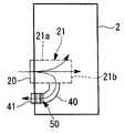
도 1은 본 발명의 풍력 발전 장치에 관한 제1 실시 형태를 도시하는 도면으로, (a)는 타워 표면에 설치한 타워 개구의 실개구 면적 및 유효 개구 면적을 도시하는 사시도, (b)는 (a)의 A-A 단면도이다.
도 2는 풍력 발전 장치의 개요를 도시하는 측면도이다.
도 3은 타워 개구의 설치예를 도시하는 도 2의 B부 확대도이다.
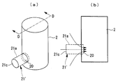
도 4는 도 1에 도시하는 실개구 면적 및 유효 개구 면적의 변형예를 도시하는 도면으로, (a)는 제1 변형예를 도시하는 종단면도, (b)는 제2 변형예를 도시하는 수평 단면도이다.
도 5는 타워 표면에 설치하는 타워 개구의 실개구 면적의 형상예를 나타내는 정면도로, (a)는 정사각형, (b)는 세로로 긴 직사각형, (c)는 대략 타원형상이다.
도 6은 본 발명의 풍력 발전 장치에 관한 제2 실시 형태로서, 환기 팬을 구비한 실개구 면적 및 유효 개구 면적의 구성예를 도시하는 종단면도이다.
도 7은 도 6에 도시한 구성예의 제1 변형예를 도시하는 종단면도이다.
도 8은 본 발명의 풍력 발전 장치에 관한 제3 실시 형태로서, 열 교환기를 구비한 구성예를 도시하는 종단면도이다.
도 9는 도 8에 도시한 구성예의 제1 변형예를 도시하는 종단면도로, (a)는 종단면도, (b)는 (a)의 C-C 단면도이다.
도 10은 도 8에 도시한 구성예의 제2 변형예를 도시하는 종단면도이다.
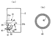
도 11은 본 발명의 풍력 발전 장치에 관한 제4 실시 형태를 도시하는 도면으로, (a)는 타워 표면에 설치한 타워 개구의 실개구 면적 및 유효 개구 면적을 도시하는 사시도, (b)는 (a)의 D-D 단면도이다.
도 12는 도 11에 도시한 제4 실시 형태에 따른 제1 변형예를 도시하는 도면으로, (a)는 실개구 면적 및 유효 개구 면적을 도시하는 사시도, (b)는 (a)의 E-E 단면도이다.
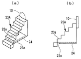
도 13은 도 11에 도시한 제4 실시 형태에 따른 제2 변형예를 도시하는 도면으로, (a)는 실개구 면적 및 유효 개구 면적을 도시하는 사시도, (b)는 (a)의 F-F 단면도이다.
도 14는 도 11에 도시한 제4 실시 형태에 따른 제3 변형예를 도시하는 도면으로, (a)는 실개구 면적 및 유효 개구 면적을 도시하는 측면도, (b)는 (a)의 사시도이다.
도 15는 도 11에 도시한 제4 실시 형태에 따른 제4 변형예를 도시하는 도면으로, (a)는 실개구 면적 및 유효 개구 면적을 도시하는 사시도, (b)는 (a)의 측면도이다.
도 16은 도 11에 도시한 제4 실시 형태에 따른 제5 변형예를 도시하는 측면도이다.
도 17은 도 11에 도시한 제4 실시 형태에 따른 제6 변형예를 도시하는 측면도이다.
도 18은 종래의 풍력 발전 장치에 있어서, 기기 손실을 타워 개구부로부터 도입한 외기의 순환에 의해 냉각하는 개념도이다.BRIEF DESCRIPTION OF THE DRAWINGS It is a figure which shows 1st embodiment which concerns on the wind power generator of this invention, (a) is a perspective view which shows the real opening area and the effective opening area of the tower opening provided in the tower surface, (b) ( AA section of a).
2 is a side view illustrating an outline of a wind turbine generator.
3 is an enlarged view of a portion B of FIG. 2 showing an example of installation of a tower opening.
4 is a diagram showing a modification of the actual opening area and the effective opening area shown in FIG. 1, (a) is a longitudinal sectional view showing the first modification, and (b) is a horizontal showing the second modification. It is a cross section.
Fig. 5 is a front view showing a shape example of the actual opening area of the tower opening provided on the tower surface, (a) is a square, (b) is a vertically long rectangle, and (c) is substantially elliptical.
FIG. 6: is a longitudinal cross-sectional view which shows the structural example of the real opening area and effective opening area provided with the ventilation fan as 2nd Embodiment which concerns on the wind power generator of this invention.
FIG. 7 is a longitudinal cross-sectional view showing the first modification to the structural example shown in FIG. 6.
FIG. 8: is a longitudinal cross-sectional view which shows the structural example provided with the heat exchanger as 3rd Embodiment which concerns on the wind turbine generator of this invention.
FIG. 9 is a longitudinal sectional view showing a first modification of the structural example shown in FIG. 8, (a) is a longitudinal sectional view, and (b) is a CC sectional view of (a).
FIG. 10 is a longitudinal cross-sectional view showing a second modification to the structural example shown in FIG. 8. FIG.
FIG. 11 is a view showing a fourth embodiment of the wind turbine generator according to the present invention, (a) is a perspective view showing the actual opening area and the effective opening area of the tower opening provided on the tower surface, (b) ( It is DD sectional drawing of a).
FIG. 12 is a view showing a first modification example according to the fourth embodiment shown in FIG. 11, (a) is a perspective view showing an actual opening area and an effective opening area, and (b) is an EE cross-sectional view of (a). to be.
It is a figure which shows the 2nd modified example which concerns on 4th embodiment shown in FIG. 11, (a) is a perspective view which shows a real opening area and an effective opening area, (b) is FF sectional drawing of (a). to be.
It is a figure which shows the 3rd modified example which concerns on 4th embodiment shown in FIG. 11, (a) is a side view which shows a real opening area and an effective opening area, (b) is a perspective view of (a). .
It is a figure which shows the 4th modified example which concerns on 4th embodiment shown in FIG. 11, (a) is a perspective view which shows a real opening area and an effective opening area, (b) is a side view of (a). .
FIG. 16 is a side view illustrating a fifth modification example according to the fourth embodiment illustrated in FIG. 11.
17 is a side view illustrating a sixth modification example according to the fourth embodiment shown in FIG. 11.
18 is a conceptual diagram of cooling a device loss by circulation of external air introduced from a tower opening in a conventional wind turbine generator.
이하, 본 발명에 따른 풍력 발전 장치의 일 실시 형태를 도면에 기초하여 설명한다.EMBODIMENT OF THE INVENTION Hereinafter, one Embodiment of the wind power generator which concerns on this invention is described based on drawing.
도 2에 도시하는 풍력 발전 장치(1)는, 기초 B 위에 세워 설치되는 풍차용 타워(이하에서는, 「타워」라 함)(2)와, 타워(2)의 상단부에 설치되는 너셀(3)과, 대략 수평한 횡방향의 회전축선 주위로 회전 가능하게 지지되어 너셀(3)의 전단부측에 설치되는 로터 헤드(4)를 갖고 있다.The
로터 헤드(4)에는, 그 회전축선 주위에 방사상으로서 복수매(예를 들어 3매)의 풍차 날개(5)가 장착되어 있다. 이에 의해, 로터 헤드(4)의 회전축선 방향으로부터 풍차 날개(5)에 맞닿는 바람의 힘이, 로터 헤드(4)를 회전축선 주위로 회전시키는 동력으로 변환되도록 되어 있다.The
타워(2)의 하단부 부근에는, 타워 내에 출입하기 위한 도어(6)가 설치되어 있다.Near the lower end of the
너셀(3)의 외주면 적소(예를 들어 상부 등)에는, 주변의 풍속값을 측정하는 풍속계(7)나 풍향을 측정하는 풍향계(8) 등이 설치되어 있다.The anemometer 7 which measures the surrounding wind speed value, the wind vane 8 which measures a wind direction, etc. are provided in the outer peripheral surface place (for example, upper part etc.) of the
즉, 풍력 발전 장치(1)는, 풍차 날개(5)에 풍력을 받아서 대략 수평한 회전축선 주위로 회전하는 로터 헤드(4)가 너셀(3)의 내부에 설치된 발전기(도시하지 않음)를 구동해서 발전하는 동시에, 너셀(3)이 철근 콘크리트제의 기초 B 위에 세워 설치된 타워(2)의 상단부에 설치되어 요 선회 가능하게 된다.That is, the
또한, 도시한 타워(2)는 강제의 모노폴식으로 되어, 복수로 분할한 타워 섹션의 플랜지(도시하지 않음)를 접속함으로써, 필요한 길이(높이)를 확보한 원통 타워가 된다.In addition, the illustrated
<제1 실시 형태><1st embodiment>
상술한 풍력 발전 장치(1)는, 예를 들어 도 1에 도시한 바와 같이, 타워(2)의 표면에 설치한 타워 개구(20)로부터 타워 내부에 외기를 도입하고, 기기 손실에 수반하는 발열에 의해 온도 상승한 내부 공기를 냉각하게 되어 있다. 이 경우의 기기 손실에 수반하는 발열로서는, 예를 들어 컨버터 등의 전기 기기류나 증속기 등의 회전 기기류에 의한 운전 시의 발열이 있으며, 이들 발열 기기류는 일반적으로 타워(2)나 너셀(3)의 내부에 배치되어 있다.As described above, for example, as illustrated in FIG. 1, the above-described
본 실시 형태에서는, 상술한 기기 손실의 냉각을 행하기 위해서, 타워 개구(20)로부터 타워 내측으로 연장하는 오목부가 되는 통형상부(21)를 형성하고, 통형상부(21)를 구성하는 면의 일부 또는 전부를 압력 손실 요소 설치용 유효 개구 면적 Se로서 확보한다. 이 유효 개구 면적 Se는, 설치된 압력 손실 요소를 거쳐서 통기 가능하게 구성되고, 압력 손실 요소를 설치한 유효 개구 면적 Se가 타워 개구(20)의 실개구 면적 S보다도 크게(Se>S) 되어 있다. 즉, 본 실시 형태에서는, 유효 개구 면적 Se가 되는 주위면적이 실개구 면적 S보다 크게(Se>S) 되도록, 타워 개구(20)로부터 타워 내부로 쑥 들어가도록 해서 깊숙히 들어가 있는(오목하게 되어 있는) 통형상부(21)를 형성한다. 이 통형상부(21)를 구성하는 주위면(21a) 및 타워 내측 단부면(21b)의 전부 또는 일부가 유효 개구 면적 Se로서 사용된다. 또한, 도면 중 통형상부(21)에서 파선 표시한 부분은, 압력 손실 요소의 설치에 의해 외기의 유통이 가능해지는 영역이다.In this embodiment, in order to cool the apparatus loss mentioned above, the surface which comprises the
구체적으로 설명하면, 도 1에 도시하는 통형상부(21)는, 타워(2)의 타워 외표면에 개구하는 타워 개구(20)로부터 타워 내부를 향해서 연장하는 원통형상이 된다. 도시한 구성예에서는, 통형상부(21)를 타워(2)의 축 중심 방향을 향한 원통형상으로 하고 있지만, 통 단면형상이나 연장 방향이 이에 한정되지는 않는다.Specifically, the
또한, 상술한 통형상부(21)는, 예를 들어 골격 부재(도시하지 않음)를 격자형상으로 조합하여 통형상을 형성하고, 그 주위면 및 양단부면을 개구시키고 있다. 이와 같이 해서 형성된 통형상부(21)의 개구는, 타워 개구(20)가 되는 타워 외의 원통 단부면(타워 외측 단부면)을 제외하고, 주위면(21a) 및 타워 내측 단부면(21b)의 전부 또는 일부를 실개구 면적 Se로서 사용하는 것이 가능하며, 압력 손실 요소가 되는 환기용소창, 필터 및 제염 필터 등의 설치에 이용된다. 또한, 압력 손실 요소의 고정 지지는, 예를 들어 상술한 골격 부재를 사용해서 용이하게 실시 가능하다.In addition, the
이 결과, 타워 개구(20)의 개구 면적과 대략 일치하는 통형상부(21)의 타워 외측 단부면의 면적이 실개구 면적 S가 되고, 따라서, 이 경우의 유효 개구 면적 Se는, 대략 주위면(21a)의 면적분만큼 실개구 면적 S보다 커진다. 도시한 구성예에서는, 타워 내측 단부면(21b)의 면적도 실개구 면적 Se가 되지만, 타워 내측 단부면(21b)의 면적을 실개구 면적 Se로서 사용할 수 없는 경우에는, 주위면(21a)의 면적으로부터 실개구 면적 S를 뺀 면적이 유효 개구 면적 Se가 된다. 이러한 통형상부(21)의 주위면(21a)은, 축 방향 길이나 직경을 변경해서 적절하게 면적을 조정하는 것이 가능하다.As a result, the area of the tower outer end surface of the
또한, 통형상부(21)의 유효 개구 면적 Se는, 엄밀하게는 골격 부재의 분만큼 작아지지만, 골격 부재에 의해 막히는 면적은, 통상은 주위면(21a)의 면적과 비교하면 충분히 작은 것이 된다.In addition, although the effective opening area Se of the
이러한 타워 개구(20) 및 통형상부(21)는, 타워(2)의 적소에 설치하면 되지만, 예를 들어 도 3에 도시한 바와 같이, 도어(6)를 설치하기 위한 도어용 개구부(10)를 이용해서 설치해도 된다. 이 도어용 개구부(10)는, 메인터넌스 작업 등의 목적으로 타워(2)의 내부에 출입하는 도어(6)가 필요해지기 때문에, 통상은 타워(2)에 반드시 설치되어 있는 개구부이다. 이 때문에, 도어용 개구부(10)를 적어도 일부를 유효하게 이용하고, 타워 개구(20)의 실개구 면적 S보다 큰 유효 개구 면적 Se를 용이하게 형성할 수 있다. 도시한 구성예에서는, 도어용 개구부(10)가 세로로 긴 대략 타원형상이 되고, 도어(6)의 상부에 남은 대략 반타원형상의 스페이스를 이용해서 타워 개구(20)를 배치하고 있다.Although the
또한, 타워(2) 내로의 출입구가 되는 도어(6)에 대해서는, 타워 개구(20)로부터 타워 내측으로 연장하는 오목부가 되는 통형상부(21)의 구성면을 이용해서 설치 가능하며, 구성면 중 어느 하나에 개폐 가능한 도어(6)를 장착하면 된다.In addition, about the
상술한 바와 같이, 본 실시 형태의 풍력 발전 장치(1)는, 타워 개구(20)로부터 타워 내측으로 연장하는 오목부가 되는 통형상부(21)를 형성하고, 통형상부(21)의 구성면을 사용해서 타워 개구(20)의 실개구 면적 S보다 큰 압력 손실 요소 설치용 유효 개구 면적 Se를 확보했으므로, 타워 개구(20)의 면적을 최소한으로 억제해서 타워 강도를 확보하는 동시에, 큰 유효 개구 면적 Se에 설치한 압력 손실 요소를 통과해서 흐르는 외기의 유속을 작게 할 수 있다. 이와 같이, 타워 개구(20)로부터 오목해지는 통형상부(21)는, 압력 손실 요소를 설치하는 장소가 타워(2)의 외면으로부터 내측으로 깊숙한 위치가 되기 때문에, 분진이나 빗물 등의 이물질이 압력 손실 요소까지 도달하기 어려운 구조가 된다.As mentioned above, the
그런데, 상술한 실시 형태의 실개구 면적 S 및 유효 개구 면적 Se는, 도 4의 (a)에 도시하는 제1 변형예 및 도 4의 (b)에 도시하는 제2 변형예와 같은 통형상부(21A, 21B)로 해도 된다.By the way, the actual opening area S and the effective opening area Se of embodiment mentioned above are cylindrical parts like the 1st modified example shown to FIG. 4A, and the 2nd modified example shown to FIG. 4B. It is good also as (21A, 21B).
도 4의 (a)에 도시하는 제1 변형예의 통형상부(21A)는, 타워(2)의 개구로부터 타워축 중심 방향으로 상향으로 경사지는 오목부가 되도록 형성되어 있다. 즉, 제1 변형예의 통형상부(21A)는, 타워(2)의 외표면에 개구하는 타워 개구(20)로부터 타워(2)의 내부를 향하여, 비스듬하게 상향으로 경사지면서 쑥 들어가도록(오목해지도록) 형성된 원통형상으로 되어 있다.The
이러한 통형상부(21A)는, 압력 손실 요소를 설치하는 장소가 타워(2)의 외면으로부터 내측으로 깊숙한 위치가 되는 데 더하여, 타워 개구(20)로부터 상향의 경사면이 형성되어 있으므로, 이물질이 압력 손실 요소까지 도달하기 어려운 구조가 된다.The
또한, 도 4의 (b)에 도시하는 제2 변형예의 통형상부(21B)는, 타워(2)의 타워 개구(20)로부터 타워축 중심 방향으로 끝으로 갈수록 넓어지는 오목부가 되도록 형성되어 있다. 이와 같이 하면, 원통형상과 비교해서 타워(2)의 내부에 큰 주위면적을 확보할 수 있기 때문에, 큰 유효 개구 면적 Se의 확보가 용이해진다.In addition, the
또한, 이 경우의 끝으로 갈수록 넓어지는 것은, 적합하게는 타워 내측으로 직경 확장하는 원추 사다리꼴형상이 되지만, 수평 방향 또는 연직 방향 중 어느 한쪽에만 끝으로 갈수록 넓어지게 해도 된다.Moreover, although it becomes a conical trapezoid shape which diameter expands suitably inside a tower suitably, it becomes wider toward the end of this case, but may widen so that it may go to the end only in either a horizontal direction or a vertical direction.
또한, 상술한 통형상부(21)는, 단면형상으로 직선부를 포함하고 있는 것이 바람직하다. 즉, 타워 개구(20)는, 원통형상의 통형상부(21)에 대응하는 원형으로 해도 되지만, 직선부를 포함한 형상으로 하는 것이 바람직하다. 실개구 면적이 되는 타워 개구(20)의 구체적인 형상예는, 예를 들어 도 5의 (a) 내지 (c)에 도시한 바와 같이, 정사각형(20A), 직사각형(20B) 및 대략 타원형상(20C) 등이 있다. 이들 타워 개구를 구비한 통형상부는, 각 타워 개구와 동일한 단면형상 그대로 오목부를 형성하면 된다.In addition, it is preferable that the
또한, 실개구 면적이 되는 타워 개구에 직선부를 포함하고 있으면, 통형상부를 형성하는 일반적인 덕트 등의 설치가 용이해진다. 특히, 직사각형(20B)이나 대략 타원형상(20C) 등과 같이, 타워 개구(20)에 세로로 긴 형상을 채용하면, 동일 면적의 원형이나 정사각형의 각형상이 개구해 있는 경우와 비교하여, 세로 길이비의 조정에 의해, 타워 직경에 대한 개구 직경의 비율이 작아지기 때문에, 타워 강도를 저하시키는 요인이 작아지므로, 타워 강도의 확보에 유효하다.Moreover, when the linear opening part is included in the tower opening used as a real opening area, installation of the general duct etc. which form a cylindrical part will become easy. In particular, when a vertically long shape is adopted in the
<제2 실시 형태>≪ Second Embodiment >
이하에서는, 본 발명에 따른 풍력 발전 장치(1)에 대해서, 제2 실시 형태를 도 6에 도시하여 설명한다. 또한, 상술한 실시 형태와 마찬가지 부분에는 동일한 부호를 붙이고, 그 상세한 설명은 생략한다.Hereinafter, 2nd Embodiment is described about FIG. 6 about the
이 실시 형태에서는, 유효 개구 면적 Se보다 하류측이 되는 타워(2)의 내부에 구획 부재(2a)를 구비하여 상하로 구획하고, 구획 부재(2a)에 외기 흡인용 팬(30)을 설치하고 있다. 이 팬(30)이 운전되면, 타워 개구(20)로부터 외기가 흡인되어 통형상부(21)의 압력 손실 부재를 통과한다. 이 외기는, 또한 팬(30) 및 타워(2)의 내부를 통과해서 너셀(3)의 내부에 공급된다.In this embodiment, the
이와 같이 구성하면, 구획 부재(2a)에 의해 타워(2) 내를 통과해서 너셀(3)에 이르는 외기 유로가 팬(30)에 한정되므로, 팬(30)의 출입구에 있어서, 외기의 흐름에 단락이 발생하는 것을 방지할 수 있다. 따라서, 타워 개구(20)로부터 효과적으로 외기를 받아들이는 것이 가능해져서, 외기에 의한 냉각 및 환기를 확실하게 행할 수 있다.When comprised in this way, since the outside air flow path which passes through the inside of the
또한, 예를 들어 도 7에 도시하는 제1 변형예와 같이, 유효 개구 면적 Se를 형성하는 면의 내측(타워(2)의 공간측)에 외기 흡인용 팬(30)을 설치하고, 외기를 적극적으로 받아들이도록 해도 된다. 즉, 통형상부(21)의 주위면(21a)에 반해, 타워(2)의 내측(너셀(3)측)이 되는 위치에 직접 팬(30)을 설치했으므로, 새롭게 구획 부재(2a)를 설치할 필요가 없다.For example, like the 1st modification shown in FIG. 7, the outside
<제3 실시 형태>≪ Third Embodiment >
이하에서는, 본 발명에 따른 풍력 발전 장치(1)에 대해서, 제3 실시 형태를 도 8에 도시하여 설명한다. 또한, 상술한 실시 형태와 마찬가지 부분에는 동일한 부호를 붙이고, 그 상세한 설명은 생략한다.Hereinafter, 3rd Embodiment is described about FIG. 8 about the
이 실시 형태에서는, 유효 개구 면적 Se의 면으로부터 분기해서 대기로 연통하는 외기의 바이패스 유로(40)를 설치하고, 이 바이패스 유로(40) 내에 외기와의 열 교환에 의해 냉각 매체를 냉각하는 열 교환기(50)를 설치하고 있다. 즉, 통형상부(21)의 주위면(21a)으로부터 분기해서 외기로 연통하는 바이패스 유로(40)를 형성하고, 이 바이패스 유로(40) 내에 냉각 매체로부터 흡열해서 냉각하는 열 교환기(50)가 설치되어 있다. 또한, 통형상부(21)의 주위면(21a)으로부터 분기해서 외기로 연통하는 바이패스 유로(40)의 입구는, 압력 손실 요소가 없어도 된다.In this embodiment, the
상술한 열 교환기(50)는 냉각 대상 기기를 순환하는 오일이나 물 등의 냉각 매체를 외기에 의해 냉각하는 것이다. 즉, 타워 개구(20)로부터 통형상부(21) 내에 도입한 저온의 외기는, 일부가 바이패스 유로(40)로 분기해서 흐르고, 열 교환기(50)를 통과할 때에 냉각 매체로부터 흡열한다. 이 결과, 냉각 대상 기기를 냉각해서 온도 상승한 냉각 매체는 외기로 방열해서 온도 저하하므로, 냉각 대상 기기에 반해 항상 저온의 냉각 매체를 공급한 냉각이 가능해진다.The
또한, 이 열 교환기(50)를 바이패스 유로(40)에 설치했으므로, 열 교환기(50)에서 흡열한 고온의 외기는 바이패스 출구(41)로부터 대기로 유출한다. 이 때문에, 열 교환기(50)의 배열이 타워(2)의 내부에 단락하지 않고, 따라서, 타워 개구(20)로부터 통형상부(21) 내에 도입한 저온의 외기는 바이패스 유로(40)로 유출한 일부를 제외하고, 압력 손실 요소를 통과해서 너셀(3)까지 도입된다.In addition, since this
이와 같이, 먼지나 빗물 등의 이물질 침입 방지가 불필요하기 때문에, 압력 손실 요소를 통과시킬 필요가 없는 외기에 대해서는, 너셀(3)을 향하는 외기의 흐름으로부터 분기하는 별도 계통의 바이패스 유로(40)를 설치해서 열 교환기(50)로 유도하므로, 냉각용으로서 도입하는 외기 전체의 압력 손실을 저감할 수 있다.In this way, since it is unnecessary to prevent foreign matter intrusion such as dust or rain water, the
이 경우, 바이패스 유로(40)의 내부에는, 예를 들어 도 9에 도시하는 제1 변형예와 같이, 흡음재(42)를 장착하는 것이 바람직하다. 이러한 흡음재(42)는, 열 교환기(50)의 가동 시에 발생하는 열 교환기 팬(51)의 운전 소음을 저감하는 데에 유효하다. 또한, 열 교환기 팬(51a)은, 통형상부(21)로부터 바이패스 유로(40) 내에 외기의 일부를 도입해서 열 교환기(51)를 통과시키기 위한 팬이며, 열 교환기(51)의 상류측 또는 하류측에 인접해서 설치되어 있다.In this case, it is preferable to mount the
또한, 도 10에 도시하는 제2 변형예와 같이, 바이패스 유로(40)의 출구측을 하향으로 연장하고, 바이패스 출구(41)를 지면을 향해서 개구시키면, 열 교환기(50)의 가동 시에 발생하는 열 교환기 팬(51)의 운전 소음이 주위로 퍼지는 것을 억제할 수 있다.In addition, as in the second modification shown in FIG. 10, when the outlet side of the
<제4 실시 형태>≪ Fourth Embodiment &
이하에서는, 본 발명에 따른 풍력 발전 장치(1)에 대해서, 제4 실시 형태를 도 11에 도시하여 설명한다. 또한, 상술한 실시 형태와 마찬가지 부분에는 동일한 부호를 붙이고, 그 상세한 설명은 생략한다.Hereinafter, the fourth embodiment of the
이 실시 형태에서는, 타워 개구(20)로부터 타워 외측으로 연장하는 볼록부의 통형상부(21A)를 형성하고, 통형상부(21A)를 구성하는 주위면(21a) 및 타워 외측 단부면(21c)의 일부 또는 전부를 사용해서 타워 개구(20)의 실개구 면적 S보다 큰 압력 손실 요소 설치용 유효 개구 면적 Se로서 확보하고 있다. 즉, 본 실시 형태에서는, 유효 개구 면적 Se가 되는 볼록부 구성면이 실개구 면적 S보다 크게(Se>S) 되도록, 타워 개구(20)로부터 타워 외부로 튀어 나오도록 해서 돌출한 볼록형상의 통형상부(21A)를 형성하고 있다.In this embodiment, the
구체적으로 설명하면, 도 11에 도시하는 통형상부(21A)는, 타워(2)의 타워 외표면에 개구하고 있는 타워 개구(20)로부터 타워 외부를 향해서 돌출한 원통형상이다. 또한, 통형상부(21A)의 통 단면형상이나 돌출 방향에 대해서는, 특별히 한정되지는 않는다.Specifically, the
또한, 상술한 통형상부(21A)는, 예를 들어 골격 부재(도시하지 않음)를 격자형상으로 조합해서 통형상을 형성하고, 그 주위면 및 양단부면을 개구시키고 있다. 이와 같이 해서 형성된 통형상부(21A)의 개구는, 타워 개구(20)가 되는 타워측의 원통 단부면(타워측 단부면)을 제외하고, 주위면(21a) 및 타워 외측 단부면(21c)이 실개구 면적 Se로서 사용 가능해져서, 압력 손실 요소의 설치에 이용된다.In addition, the
이 결과, 타워 개구(20)의 개구 면적과 대략 일치하는 통형상부(21A)의 타워측 단부면의 면적이 실개구 면적 S가 되고, 따라서, 이 경우의 유효 개구 면적 Se는, 대략 주위면(21a)의 면적분만큼 실개구 면적 S보다 커진다. 도시한 구성예에서는, 타워 외측 단부면(21c)의 면적이 실개구 면적 Se로부터 제외되어 있지만, 타워 외측 단부면(21c)의 면적을 실개구 면적 Se로서 사용할 수 있는 경우에는, 상술한 실시 형태와 마찬가지로, 주위면(21a)의 면적이 유효 개구 면적 Se가 된다. 이러한 통형상부(21A)의 주위면(21a)은, 축 방향 길이나 직경을 변경해서 적절하게 면적을 조정하는 것이 가능하다.As a result, the area of the tower-side end surface of the
이러한 타워 개구(20) 및 통형상부(21A)는, 타워(2)의 적소에 설치하면 되지만, 예를 들어 도 3에 도시한 바와 같이, 도어(6)를 설치하기 위한 도어용 개구부(10)를 이용해서 설치해도 된다.Although the
상술한 바와 같이, 본 실시 형태의 풍력 발전 장치(1)는, 타워 개구(20)로부터 타워 외측으로 연장하는 볼록부가 되는 통형상부(21A)를 형성하고, 통형상부(21A)를 구성하는 면의 일부 또는 전부를 타워 개구(20)의 실개구 면적 S보다 큰 압력 손실 요소 설치용 유효 개구 면적 Se로서 확보했으므로, 타워 개구(20)를 최소한으로 억제하여 타워 강도를 확보하는 동시에, 큰 유효 개구 면적 Se에 설치한 압력 손실 요소를 통과해서 흐르는 외기의 유속을 작게 할 수 있다.As mentioned above, the
또한, 도 12에 도시하는 본 실시 형태의 제1 변형예에 있어서, 상술한 통형상부(21A)는, 도어용 개구부(10)의 주위로부터 외향으로 돌출하는 외부 상자(22)가 되고, 외부 상자(22)의 노출면에 유효 개구 면적 Se를 확보하고 있다. 즉, 외부 상자(22)는, 도어용 개구부(10)를 둘러싸도록 하여, 타워 외측으로 연장해 있다. 이 경우의 노출면은, 외부 상자(22)를 대략 각기둥형상으로 하고, 지면으로부터 도어용 개구부(10)를 향해서 직선적으로 경사지는 배치로 한 것이므로, 저면을 포함하는 주위의 4면을 유효 개구 면적 Se로서 이용할 수 있다. 따라서, 도어용 개구부(10)가 규정하는 실개구 면적 S와 비교하여, 보다 큰 유효 개구 면적 Se를 용이하게 확보할 수 있다.In addition, in the 1st modified example of this embodiment shown in FIG. 12, 21 A of cylindrical parts mentioned above become the
또한, 외부 상자(22)의 경사 배치는, 도시한 직선적인 경사에 한정되지는 않고, 예를 들어 도중에 수평부를 갖는 복수 단계의 경사로 해도 된다.In addition, the inclination arrangement | positioning of the
이 경우, 외부 상자(22)의 지면 설치측이 되는 단부면(22a)에 도어(도시하지 않음)가 장착되고, 도어용 개구부(10)는 외기 통로로서 상시 개방되어 있다. 그리고, 외부 상자(22) 중에는, 즉 외부 상자(22)의 공간 내에는, 타워 입구가 되는 도어용 개구부(10)까지 오르는 계단을 형성하는 것도 가능하다.In this case, the door (not shown) is attached to the
또한, 외부 상자(22)의 형상은 대략 각기둥형상으로 한정되지 않고, 예를 들어 도어용 개구부(10)와 동일한 단면형상을 갖는 통형상으로 해도 된다.In addition, the shape of the
또한, 도 13에 도시하는 본 실시 형태의 제2 변형예에 있어서, 상술한 통형상부(21A)는, 도어용 개구부(10)의 하단부측으로부터 돌출하는 계단모양 외부 상자(23)로 되어, 도어용 개구부(10)의 하단부측을 실개구 면적 S라 하고, 또한 계단모양 외부 상자(23)의 양측면에 유효 개구 면적 Se를 확보하고 있다. 즉, 계단모양 외부 상자(23)는, 상면에 계단(트랩)(23a)이 형성된 중공의 상자형상 부재이며, 양측면(23b)이 압력 손실 요소의 설치면이 된다.In addition, in the 2nd modified example of this embodiment shown in FIG. 13, 21 A of cylindrical parts mentioned above become the staircase
이 경우, 도어용 개구부(10)의 상부 영역(10a)을 도어 설치면으로서 닫고, 계단(23a)으로부터 하방의 하부 영역(10b)이 외기를 통과시키는 유로로서 상시 개구되어 있다.In this case, the
또한, 도 14에 도시하는 본 실시 형태의 제3 변형예에 있어서는, 외부 상자(22A)의 저면(22b)과 지면 사이에 외기가 유통 가능한 공간을 형성하고, 저면(22b)에 유효 개구 면적 Se를 확보해서 압력 손실 요소(24)를 설치해도 된다.In addition, in the 3rd modified example of this embodiment shown in FIG. 14, the space which the outside air can distribute | circulate between the
마찬가지로, 도 15에 도시하는 본 실시 형태의 제4 변형예에서는, 계단모양 외부 상자(23A)의 저면(23c)과 지면 사이에 외기가 유통 가능한 공간을 형성하고, 저면(23c)에 유효 개구 면적 Se를 확보해서 압력 손실 요소(24)을 설치해도 된다.Similarly, in the 4th modified example of this embodiment shown in FIG. 15, the space which the outside air can distribute | circulate between the
이와 같이, 외부 상자(22A)의 저면(22b)이나 계단모양 외부 상자(23A)의 저면(23c)에 유효 개구 면적 Se를 확보해서 압력 손실 요소(24)을 설치하면, 분진이나 빗물 등의 이물질이 압력 손실 요소(24)까지 도달하기 어려운 구조가 된다.Thus, when the effective opening area Se is secured to the
또한, 도 16에 도시하는 제5 변형예 및 도 17에 도시하는 제6 변형예와 같이, 외부 상자(22B) 또는 계단모양 외부 상자(23B)의 내부에, 도면 중에 화살표로 나타내는 독립한 외기 순환 유로(25)를 형성하는 기기 설치 공간(26)을 구비한 구조로 하여, 예를 들어 기기 설치 공간(26) 내에 열 교환기(50)를 설치해도 된다. 이 경우, 기기 설치 공간(26)은 구획 부재(27)에 의해 타워(2)의 도어용 개구부(10)에 외기를 유도하는 공간으로부터 분리되고, 지면 설치측 단부면의 적소나 계단(23a)의 적소 등에 열 교환기(50)와의 열 교환에 의해 온도 상승한 외기의 출구가 설치되어 있다.In addition, as in the fifth modification example shown in FIG. 16 and the sixth modification example shown in FIG. 17, independent outside air circulation indicated by arrows in the figure inside the
이와 같은 구성으로 하면, 열 교환기(50)의 배열이 타워(2) 내에 단락해서 유입하는 것을 방지할 수 있다.With such a configuration, the arrangement of the
또한, 상기 각 실시 형태 및 그 변형예에 있어서는, 큰 유효 개구 면적 Se를 확보할 수 있으므로, 압력 손실 요소로서 저압력 손실의 필터를 장착해도 충분한 필터 능력을 얻을 수 있다.Moreover, in each said embodiment and its modification, since large effective opening area Se can be ensured, even if a filter of low pressure loss is attached as a pressure loss element, sufficient filter capability can be obtained.
이와 같이, 상술한 각 실시 형태 및 그 변형예에 따르면, 타워(2)의 표면에 뚫은 타워 개구(20)의 실개구 면적 S에 대하여 큰 면적비를 갖는 유효 개구 면적 Se를 확보할 수 있게 되므로, 타워 강도를 확보하면서 흡배기용 큰 개구 면적을 확보하는 것이 가능하게 된다.As described above, according to the above-described embodiments and modifications thereof, the effective opening area Se having a large area ratio can be ensured with respect to the actual opening area S of the
또한, 본 발명은 상술한 실시 형태에 한정되지는 않고, 예를 들어 오목의 통형상에서 설명한 실시 형태나 변형예를 볼록한 통형상에 적용하는 등, 그 요지를 일탈하지 않는 범위 내에 있어서 적절하게 변경할 수 있다.In addition, this invention is not limited to embodiment mentioned above, For example, it changes suitably within the range which does not deviate from the summary, for example, applying embodiment or modified example demonstrated in concave cylindrical shape to convex cylindrical shape. Can be.
1 : 풍력 발전 장치
2 : 풍차용 타워
2a : 구획 부재
3 : 너셀
4 : 로터 헤드
5 : 풍차 날개
6 : 도어
10 : 도어용 개구부
20, 20A ~ 20C : 타워 개구
21, 21′, 21A, 21B : 통형상부
22, 22A, 22B : 외부 상자
23, 23A, 23B : 계단모양 외부 상자
30 : 팬
40 : 바이패스 유로
41 : 바이패스 출구
42 : 흡음재
50 : 열 교환기1: Wind generator
2: windmill tower
2a: partition member
3: Nussel
4: rotor head
5: windmill wings
6: door
10: opening for door
20, 20A ~ 20C: tower opening
21, 21 ′, 21A, 21B: cylindrical part
22, 22A, 22B: outer box
23, 23A, 23B: Staircase Outer Box
30: fan
40: bypass euro
41: bypass exit
42: sound absorbing material
50: heat exchanger
Claims (16)
상기 타워 개구로부터 타워 내측으로 연장하는 오목부 또는 상기 타워 개구로부터 타워 외측으로 연장하는 볼록부를 갖고,
상기 오목부 또는 상기 볼록부를 구성하는 면의 일부 또는 전부에 설치된 압력 손실 요소를 거쳐서 통기 가능하게 구성되는 동시에, 상기 압력 손실 요소를 설치한 유효 개구 면적이 상기 타워 개구의 실개구 면적보다도 큰, 풍력 발전 장치.The rotor head, which receives and rotates wind power on the windmill blades, generates power by driving a generator installed in the interior of the nussel. In the wind power generator for cooling the internal space by introducing outside air,
A concave extending from the tower opening into the tower or a convex extending from the tower opening to the outside of the tower;
Wind power, which is configured to be ventilated via a pressure loss element provided in part or all of the surface constituting the recess or the convex portion, and the effective opening area provided with the pressure loss element is larger than the actual opening area of the tower opening. Power generation device.
상기 타워 개구는, 타워 내부에 출입하기 위한 도어를 설치하는 도어용 개구부 중 적어도 일부가 이용되는, 풍력 발전 장치.The method of claim 1,
The tower opening is a wind turbine generator, at least part of the door opening for installing a door for entering and exiting inside the tower is used.
상기 오목부 또는 상기 볼록부는, 그 구성면 중 어느 하나의 위치에 개폐 가능한 출입구를 구비하고 있는, 풍력 발전 장치.The method according to claim 1 or 2,
The said recessed part or the said convex part is provided with the entrance / exit which can be opened and closed in any one position of the structure surface.
상기 오목부 또는 상기 볼록부는, 상기 타워 개구로부터 끝으로 갈수록 넓어지게 형성되어 있는, 풍력 발전 장치.4. The method according to any one of claims 1 to 3,
The concave portion or the convex portion is formed to be wider toward the end from the tower opening.
상기 오목부는, 상기 타워 개구로부터 타워축 중심 방향으로 상향으로 경사져 있는, 풍력 발전 장치.5. The method according to any one of claims 1 to 4,
The concave portion is inclined upward from the tower opening toward the center of the tower axis.
상기 오목부 또는 상기 볼록부의 단면형상이 직선부를 포함하고 있는, 풍력 발전 장치.The method of claim 1,
The cross-sectional shape of the said recessed part or said convex part contains a straight part.
상기 볼록부가 상기 도어용 개구부의 주위로부터 돌출하는 외부 상자로 되고, 상기 외부 상자의 노출면에 상기 유효 개구 면적을 확보한, 풍력 발전 장치.The method of claim 2,
The wind turbine generator of which the said convex part becomes an outer box which protrudes from the periphery of the said opening part for doors, and secured the said effective opening area to the exposed surface of the said outer box.
상기 오목부 또는 볼록부가, 상기 도어용 개구부의 하단부측으로부터 돌출하는 계단모양 외부 상자이며, 상기 도어용 개구부의 하단부측을 상기 실개구 면적이라 하고, 또한 상기 계단모양 외부 상자의 구성면의 전부 또는 일부에 상기 유효 개구 면적을 확보한, 풍력 발전 장치.The method of claim 2,
The said recessed part or convex part is a staircase outer box which protrudes from the lower end side of the said opening part for doors, The lower end side of the said door opening part is called the said thread opening area, and all or part of the structure surface of the said staircase outer box. The wind power generator which secured the said effective opening area to the.
상기 외부 상자 또는 상기 계단모양 외부 상자의 저면과 지면 사이에 공간을 형성하고, 상기 저면에 상기 유효 개구 면적을 확보한 것을 특징으로 하는, 풍력 발전 장치.9. The method according to claim 7 or 8,
And a space formed between the bottom surface of the outer box or the stepped outer box and the ground, and the effective opening area is secured to the bottom face.
상기 외부 상자 또는 상기 계단모양 외부 상자의 내부에 독립한 외기 순환 유로를 구비한 기기 설치 공간을 형성한, 풍력 발전 장치.10. The method according to any one of claims 7 to 9,
The wind turbine generator which formed the apparatus installation space provided with the independent outside circulation flow path inside the said outer box or the said stepped outer box.
상기 유효 개구 면적에 저압력 손실의 필터가 장착되어 있는, 풍력 발전 장치.11. The method according to any one of claims 1 to 10,
And a low pressure loss filter is attached to the effective opening area.
상기 유효 개구 면적보다 하류측이 되는 상기 타워 내에 구획을 설치해서 외기 흡인용 팬을 설치한, 풍력 발전 장치.12. The method according to any one of claims 1 to 11,
The wind turbine generator which provided the compartment in the said tower which becomes downstream from the said effective opening area, and provided the fan for external air suction.
상기 유효 개구 면적을 형성하는 면의 내측에 외기 흡인용 팬이 설치되어 있는, 풍력 발전 장치.12. The method according to any one of claims 1 to 11,
The wind power generator which is provided with the fan for outside air suction inside the surface which forms the said effective opening area.
상기 유효 개구 면적의 면으로부터 분기해서 대기로 연통하는 외기의 바이패스 유로를 설치하고, 상기 바이패스 유로 내에 외기와의 열 교환에 의해 냉각 매체를 냉각하는 열 교환기를 설치한, 풍력 발전 장치.13. The method according to any one of claims 1 to 12,
The wind turbine generator which provided the bypass flow path of the outside air which branches off from the surface of the said effective opening area, and communicates with air, and provided the heat exchanger which cools a cooling medium by heat exchange with outside air in the said bypass flow path.
상기 바이패스 유로 내에 흡음재를 장착한, 풍력 발전 장치.15. The method of claim 14,
The wind turbine generator which mounted the sound absorbing material in the said bypass flow path.
상기 바이패스 유로의 출구측을 연장해서 지면을 향해서 개구시킨, 풍력 발전 장치.16. The method according to claim 14 or 15,
The wind power generator which extended the exit side of the said bypass flow path and opened toward the ground.
Applications Claiming Priority (2)
| Application Number | Priority Date | Filing Date | Title |
|---|---|---|---|
| JPJP-P-2010-025380 | 2010-02-08 | ||
| JP2010025380A JP5595057B2 (en) | 2010-02-08 | 2010-02-08 | Wind power generator |
Publications (1)
| Publication Number | Publication Date |
|---|---|
| KR20120115361A true KR20120115361A (en) | 2012-10-17 |
Family
ID=44355553
Family Applications (1)
| Application Number | Title | Priority Date | Filing Date |
|---|---|---|---|
| KR1020127020622A KR20120115361A (en) | 2010-02-08 | 2011-02-07 | Wind-powered electrical generator |
Country Status (7)
| Country | Link |
|---|---|
| US (1) | US20130009405A1 (en) |
| EP (1) | EP2535580A1 (en) |
| JP (1) | JP5595057B2 (en) |
| KR (1) | KR20120115361A (en) |
| CN (1) | CN102753822A (en) |
| AU (1) | AU2011211633A1 (en) |
| WO (1) | WO2011096560A1 (en) |
Families Citing this family (13)
| Publication number | Priority date | Publication date | Assignee | Title |
|---|---|---|---|---|
| JP5455508B2 (en) * | 2009-08-28 | 2014-03-26 | 三菱重工業株式会社 | Wind turbine for wind power generation |
| DE102009051425A1 (en) * | 2009-10-30 | 2011-05-05 | Voith Patent Gmbh | Flow power plant and method for its creation |
| JP5992176B2 (en) * | 2012-02-10 | 2016-09-14 | エムエイチアイ ヴェスタス オフショア ウィンド エー/エス | Wind power generator |
| CN104047811A (en) * | 2013-03-12 | 2014-09-17 | 上海电气风能有限公司 | Ventilation and filter system for tower bottom of wind driven generator |
| JP2015068170A (en) | 2013-09-26 | 2015-04-13 | 三菱重工業株式会社 | Regenerative energy type power generation device |
| DK2937562T3 (en) * | 2014-04-25 | 2017-10-16 | Siemens Ag | Device for attenuating acoustic noise caused by air cooling of at least one wind turbine component provided with the nacelle of a wind turbine |
| CN104791197B (en) * | 2015-03-05 | 2018-07-17 | 中国船舶重工集团海装风电股份有限公司 | Adverse circumstances apparatus for lower wind generator set heat radiation design method and cooling system |
| US9782710B2 (en) * | 2015-07-01 | 2017-10-10 | General Electric Company | Multi-sided ventilation assembly for wind turbine tower access door |
| DE102015212321A1 (en) | 2015-07-01 | 2017-01-05 | Wobben Properties Gmbh | Wind turbine and cooling device for a wind turbine |
| WO2017008817A1 (en) * | 2015-07-16 | 2017-01-19 | Mhi Vestas Offshore Wind A/S | A cooling panel assembly for a wind turbine tower and a wind turbine tower |
| CN106150929B (en) | 2016-08-05 | 2020-12-01 | 江苏金风科技有限公司 | Tower bottom cooling device of wind generating set and control method |
| US10954922B2 (en) | 2019-06-10 | 2021-03-23 | General Electric Company | System and method for cooling a tower of a wind turbine |
| EP4083413B1 (en) * | 2021-04-28 | 2024-05-15 | General Electric Renovables España S.L. | Back-up power supply for wind turbines |
Family Cites Families (28)
| Publication number | Priority date | Publication date | Assignee | Title |
|---|---|---|---|---|
| US4499034A (en) * | 1982-09-02 | 1985-02-12 | The United States Of America As Represented By The United States Department Of Energy | Vortex-augmented cooling tower-windmill combination |
| EP1038103A1 (en) * | 1997-12-08 | 2000-09-27 | Siemens Aktiengesellschaft | Wind power plat and method for cooling a generator in a wind power plant |
| DE19947915A1 (en) * | 1999-10-06 | 2001-04-12 | Abb Research Ltd | Cooling system for wind power system components, feeds air flow at least partly produced by chimney effect through system in tower foot region through tower, machine room to air outlet |
| ITTO20020908A1 (en) * | 2002-10-17 | 2004-04-18 | Lorenzo Battisti | ANTI-ICE SYSTEM FOR WIND SYSTEMS. |
| US7938615B2 (en) * | 2003-09-11 | 2011-05-10 | Louis Michaud | Enhanced vortex engine |
| FR2874240B1 (en) * | 2004-08-11 | 2006-11-24 | Michel Alain Coustou | AEROGENERATOR TOWER (COMBINING CHIMNEY EFFECT, GREENHOUSE EFFECT, CORIOLIS FORCE AND VENTURI EFFECT) |
| US7168251B1 (en) | 2005-12-14 | 2007-01-30 | General Electric Company | Wind energy turbine |
| JP4640182B2 (en) * | 2006-01-13 | 2011-03-02 | パナソニック電工株式会社 | Lighting pole |
| DK2002120T3 (en) * | 2006-03-25 | 2010-03-15 | Clipper Windpower Technology Inc | Heat management system for a wind turbine |
| DE102006043936C5 (en) * | 2006-09-14 | 2017-03-30 | Senvion Gmbh | Ventilation of a wind turbine |
| US7615884B2 (en) * | 2007-01-30 | 2009-11-10 | Mcmastercorp, Inc. | Hybrid wind turbine system, apparatus and method |
| US20090230691A1 (en) * | 2007-03-23 | 2009-09-17 | Presz Jr Walter M | Wind turbine with mixers and ejectors |
| JP2008309122A (en) * | 2007-06-18 | 2008-12-25 | Ebara Corp | Wind powered generator apparatus |
| DE102008012664A1 (en) * | 2008-01-30 | 2009-08-06 | Repower Systems Ag | Wind turbine and a tower or tower segment and a door frame for it |
| DE102008019271A1 (en) * | 2008-04-16 | 2009-10-22 | Kenersys Gmbh | Wind turbine with improved cooling air flow |
| AU2009203009A1 (en) * | 2008-08-06 | 2010-02-25 | Code Valley Corp Pty Ltd | Cooling system |
| DK2182618T3 (en) * | 2008-10-28 | 2012-10-29 | Siemens Ag | Device for cooling an electric machine |
| US7748946B2 (en) * | 2008-12-09 | 2010-07-06 | General Electric Company | Cooling system and method for wind turbine components |
| US20100171314A1 (en) * | 2009-01-08 | 2010-07-08 | Justin Dale Tackett | Vertically Oriented Wind Tower Generator |
| US8421265B2 (en) * | 2009-02-09 | 2013-04-16 | Grayhawke Applied Technologies | System and method for generating electricity within a building structure |
| US7837126B2 (en) * | 2009-09-25 | 2010-11-23 | General Electric Company | Method and system for cooling a wind turbine structure |
| WO2011096080A1 (en) * | 2010-02-08 | 2011-08-11 | 三菱重工業株式会社 | Wind power generation device |
| US20110278928A1 (en) * | 2010-05-17 | 2011-11-17 | Microsoft Corporation | Wind-powered data center |
| JP5463218B2 (en) * | 2010-06-30 | 2014-04-09 | 三菱重工業株式会社 | Wind power generator |
| JP5449060B2 (en) * | 2010-06-30 | 2014-03-19 | 三菱重工業株式会社 | Wind power generator |
| KR101571614B1 (en) * | 2011-02-04 | 2015-11-24 | 가부시키가이샤 히타치세이사쿠쇼 | Wind turbine facility |
| US8992171B2 (en) * | 2011-09-01 | 2015-03-31 | Gamesa Innovation & Technology, S.L. | Energy efficient climate control system for an offshore wind turbine |
| US20130214538A1 (en) * | 2012-02-16 | 2013-08-22 | Clipper Windpower, Llc | Air Cooled Power Feeders for Wind Turbine Applications |
-
2010
- 2010-02-08 JP JP2010025380A patent/JP5595057B2/en active Active
-
2011
- 2011-02-07 WO PCT/JP2011/052490 patent/WO2011096560A1/en active Application Filing
- 2011-02-07 AU AU2011211633A patent/AU2011211633A1/en not_active Abandoned
- 2011-02-07 CN CN2011800084976A patent/CN102753822A/en active Pending
- 2011-02-07 KR KR1020127020622A patent/KR20120115361A/en not_active Application Discontinuation
- 2011-02-07 US US13/577,853 patent/US20130009405A1/en not_active Abandoned
- 2011-02-07 EP EP11739907A patent/EP2535580A1/en not_active Withdrawn
Also Published As
| Publication number | Publication date |
|---|---|
| CN102753822A (en) | 2012-10-24 |
| JP2011163179A (en) | 2011-08-25 |
| US20130009405A1 (en) | 2013-01-10 |
| WO2011096560A1 (en) | 2011-08-11 |
| EP2535580A1 (en) | 2012-12-19 |
| JP5595057B2 (en) | 2014-09-24 |
| AU2011211633A1 (en) | 2012-08-30 |
Similar Documents
| Publication | Publication Date | Title |
|---|---|---|
| KR20120115361A (en) | Wind-powered electrical generator | |
| JP5204216B2 (en) | Wind power generator | |
| KR101280172B1 (en) | Wind power generator | |
| JP5449060B2 (en) | Wind power generator | |
| US8740544B2 (en) | Wind turbine assembly with flow regulator | |
| CN102220943B (en) | Pipeline power turbine system generating potential energy by waste kinetic energy | |
| JP3989693B2 (en) | Wind power generator | |
| KR100967160B1 (en) | Wind collecting tower of wind power generator | |
| JP2011163179A5 (en) | ||
| US20120074710A1 (en) | Wind power generator | |
| KR101291177B1 (en) | Windmill | |
| JP6650318B2 (en) | Wind power generator | |
| JP5449235B2 (en) | Wind power generator | |
| TWI576512B (en) | Wind power plant | |
| KR20110114427A (en) | Wind-driven generator | |
| TWI534345B (en) | Wind power generation equipment | |
| KR101358212B1 (en) | Heat exchanger for wind generator | |
| CN104948388B (en) | Turbine wind force generator | |
| KR101329536B1 (en) | Turbo windpower generating system for cattle shed |
Legal Events
| Date | Code | Title | Description |
|---|---|---|---|
| A201 | Request for examination | ||
| E902 | Notification of reason for refusal | ||
| E601 | Decision to refuse application |