KR20120112261A - Plasma processing apparatus and plasma generation antenna - Google Patents
Plasma processing apparatus and plasma generation antenna Download PDFInfo
- Publication number
- KR20120112261A KR20120112261A KR1020120033519A KR20120033519A KR20120112261A KR 20120112261 A KR20120112261 A KR 20120112261A KR 1020120033519 A KR1020120033519 A KR 1020120033519A KR 20120033519 A KR20120033519 A KR 20120033519A KR 20120112261 A KR20120112261 A KR 20120112261A
- Authority
- KR
- South Korea
- Prior art keywords
- shower head
- plasma
- gas
- processing apparatus
- antenna
- Prior art date
Links
Images


Classifications
-
- H—ELECTRICITY
- H01—ELECTRIC ELEMENTS
- H01J—ELECTRIC DISCHARGE TUBES OR DISCHARGE LAMPS
- H01J37/00—Discharge tubes with provision for introducing objects or material to be exposed to the discharge, e.g. for the purpose of examination or processing thereof
- H01J37/32—Gas-filled discharge tubes
- H01J37/32009—Arrangements for generation of plasma specially adapted for examination or treatment of objects, e.g. plasma sources
- H01J37/32082—Radio frequency generated discharge
- H01J37/321—Radio frequency generated discharge the radio frequency energy being inductively coupled to the plasma
- H01J37/3211—Antennas, e.g. particular shapes of coils
-
- H—ELECTRICITY
- H01—ELECTRIC ELEMENTS
- H01J—ELECTRIC DISCHARGE TUBES OR DISCHARGE LAMPS
- H01J37/00—Discharge tubes with provision for introducing objects or material to be exposed to the discharge, e.g. for the purpose of examination or processing thereof
- H01J37/32—Gas-filled discharge tubes
- H01J37/32431—Constructional details of the reactor
- H01J37/3244—Gas supply means
-
- H—ELECTRICITY
- H05—ELECTRIC TECHNIQUES NOT OTHERWISE PROVIDED FOR
- H05H—PLASMA TECHNIQUE; PRODUCTION OF ACCELERATED ELECTRICALLY-CHARGED PARTICLES OR OF NEUTRONS; PRODUCTION OR ACCELERATION OF NEUTRAL MOLECULAR OR ATOMIC BEAMS
- H05H1/00—Generating plasma; Handling plasma
- H05H1/24—Generating plasma
- H05H1/46—Generating plasma using applied electromagnetic fields, e.g. high frequency or microwave energy
- H05H1/4645—Radiofrequency discharges
- H05H1/4652—Radiofrequency discharges using inductive coupling means, e.g. coils
Abstract
Description
본 발명은 플라즈마 처리 장치 및 플라즈마 발생용 안테나에 관한 것이다. 특히, 플라즈마 발생용 안테나의 구조 및 이를 이용한 플라즈마 처리 장치에 관한 것이다.The present invention relates to a plasma processing apparatus and a plasma generating antenna. In particular, the present invention relates to a structure of an antenna for plasma generation and a plasma processing apparatus using the same.
플라즈마 처리는 반도체 디바이스의 제조에 불가결한 기술이다. 최근 LSI의 고집적화 및 고속화의 요청으로부터, LSI를 구성하는 반도체 소자의 진보된 미세 가공이 요구되고 있다.Plasma processing is an indispensable technique for the manufacture of semiconductor devices. In recent years, from the request for high integration and high speed of LSI, advanced microfabrication of semiconductor elements constituting LSI is required.
그러나, 용량 결합형 플라즈마 처리 장치 및 유도 결합형 플라즈마 처리 장치에서는, 생성되는 플라즈마의 전자 온도가 높고 또한 플라즈마 밀도가 높은 영역이 한정된다. 이 때문에, 반도체 소자의 진보된 미세 가공의 요청에 따른 플라즈마 처리를 실현하는 것은 어려웠다.However, in the capacitively coupled plasma processing apparatus and the inductively coupled plasma processing apparatus, regions where the electron temperature of the generated plasma is high and the plasma density is high are limited. For this reason, it has been difficult to realize plasma processing in response to the request for advanced microfabrication of semiconductor devices.
따라서, 이러한 미세 가공을 실현하기 위해서는, 저전자 온도 또한 고플라즈마 밀도의 플라즈마를 생성하는 것이 필요하다. 이에 응하기 위하여, 마이크로파에 의해 처리 용기 내에서 표면파 플라즈마를 생성하고, 이에 의해 반도체 웨이퍼를 플라즈마 처리하는 장치가 제안되고 있다(예를 들면, 특허 문헌 1, 2를 참조).Therefore, in order to realize such microfabrication, it is necessary to generate a plasma of low electron temperature and high plasma density. In order to cope with this, an apparatus for generating surface wave plasma in a processing container by microwaves and thereby plasma processing a semiconductor wafer has been proposed (see Patent Documents 1 and 2, for example).
특허 문헌 1, 2에서는, 마이크로파를 동축관으로 전송시켜 처리 용기 내에 방사하고, 마이크로파의 표면파가 가지는 전계 에너지에 의해 가스를 여기시킴으로써, 저전자 온도이고 고플라즈마 밀도의 표면파 플라즈마를 발생시키는 플라즈마 처리 장치가 제안되고 있다.In Patent Documents 1 and 2, a plasma processing apparatus which transmits microwaves to a coaxial tube, radiates them in a processing container, and excites a gas by electric field energy of the surface waves of the microwaves, thereby generating a surface wave plasma having a low electron temperature and high plasma density. Is being proposed.
그러나 특허 문헌 1의 플라즈마 처리 장치에서는, 마이크로파를 동축관으로부터 처리 용기 내에 방사하기 위하여, 천판은 표면파 플라즈마와 슬롯의 사이를 석영 등의 유전체판으로 개재한 구조로 되어 있고, 가스는 처리 용기의 측벽으로부터 처리 용기 내로 공급되는 구조로 되고 있었다. 이와 같이, 가스를 천판 밖으로부터 공급하고 있었기 때문에, 가스의 흐름을 제어할 수 없어, 양호한 플라즈마 제어가 어려웠다. 또한, 천판을 도전체로 형성할 경우에도, 천판으로부터 처리 용기 내로 전자파를 방사할 수 있는 기구는 개시되어 있지 않았다.However, in the plasma processing apparatus of Patent Document 1, in order to radiate microwaves from a coaxial tube into a processing container, the top plate has a structure in which a surface wave plasma and a slot are interposed with a dielectric plate such as quartz, and the gas is a side wall of the processing container. It became the structure supplied from the inside into a process container. In this way, since gas was supplied from outside the top plate, the flow of gas could not be controlled and good plasma control was difficult. In addition, even when the top plate is formed of a conductor, a mechanism capable of radiating electromagnetic waves from the top plate into the processing container has not been disclosed.
상기 과제에 대하여 본 발명의 목적으로 하는 것은 가스 및 전자파를 공급 가능한 플라즈마 처리 장치 및 플라즈마 발생용 안테나를 제공하는 점에 있다.The object of the present invention is to provide a plasma processing apparatus and a plasma generating antenna capable of supplying gas and electromagnetic waves.
또한 상기 과제를 해결하기 위하여, 본 발명의 한 관점에 따르면, 플라즈마 처리가 행해지는 처리 용기와, 공급된 전자파를 투과하는 지파판과, 상기 지파판에 인접하여 설치된 샤워 헤드를 가지는 플라즈마 발생용 안테나를 구비하고, 상기 샤워 헤드는 도전체로 형성되고, 복수의 가스홀이 형성되고, 상기 복수의 가스홀과 분리된 위치에 전자파를 통과시키는 복수의 슬롯을 가지는 것을 특징으로 하는 플라즈마 처리 장치가 제공된다.Moreover, in order to solve the said subject, According to one aspect of this invention, the plasma generation antenna which has the processing container to which a plasma process is performed, the slow wave plate which permeate | transmits the supplied electromagnetic wave, and the shower head provided adjacent to the said slow wave plate. And a shower head is formed of a conductor, a plurality of gas holes are formed, and a plurality of slots for passing electromagnetic waves in a position separated from the plurality of gas holes. .
상기 플라즈마 처리 장치는 복수의 상기 플라즈마 발생용 안테나를 구비해도 된다.The plasma processing apparatus may include a plurality of antennas for generating plasma.
상기 샤워 헤드는 플라즈마 공간측에 노출된 면에 표면파를 전반시켜도 된다.The shower head may propagate the surface wave to the surface exposed on the plasma space side.
상기 샤워 헤드에는, 상기 복수의 슬롯의 내측 및 외측에 상기 복수의 가스홀이 형성되어도 된다.The plurality of gas holes may be formed in the shower head inside and outside the plurality of slots.
상기 복수의 슬롯을 구획하는 부분을 통과하고, 상기 슬롯보다 내측에 형성된 복수의 가스홀로 가스를 공급하는 가스 경로를 더 구비해도 된다.A gas path may be further provided through a portion partitioning the plurality of slots and supply gas to a plurality of gas holes formed inside the slot.
상기 가스 경로는 복수의 가스를 별도로 공급 가능한 복수의 가스 경로로 나뉘어 형성되어도 된다.The gas path may be divided into a plurality of gas paths that can separately supply a plurality of gases.
상기 샤워 헤드에 직류 전압을 인가하는 기구를 더 구비해도 된다.A mechanism for applying a DC voltage to the shower head may be further provided.
상기 샤워 헤드에 직류 전압을 인가하는 기구는 상기 동축관과의 사이에 절연 부재를 가져도 된다.The mechanism for applying the DC voltage to the shower head may have an insulating member between the coaxial tube.
상기 복수의 슬롯에는 유전 부재가 충전되어도 된다.The plurality of slots may be filled with a dielectric member.
상기 복수의 슬롯은, 상기 플라즈마 발생용 안테나의 중심축에 대하여 축대칭으로 형성되어도 된다.The plurality of slots may be formed in axisymmetric with respect to a central axis of the plasma generating antenna.
상기 샤워 헤드의 표면에는 용사가 실시되거나 또는 천판이 고정되고, 상기 복수의 슬롯 및 상기 복수의 가스홀에 연통하는 개구가 형성되어도 된다.Spraying may be performed on the surface of the shower head, or a top plate may be fixed, and an opening communicating with the plurality of slots and the plurality of gas holes may be formed.
상기 샤워 헤드는 실리콘에 의해 형성되고, 상기 샤워 헤드의 표면은 노출되어도 된다.The shower head may be formed of silicon, and the surface of the shower head may be exposed.
상기 과제를 해결하기 위하여, 본 발명의 다른 관점에 따르면, 도전체로 형성되고, 복수의 가스홀과, 상기 복수의 가스홀과 분리된 위치에 전자파를 통과시키는 복수의 슬롯을 가지는 샤워 헤드를 구비하는 것을 특징으로 하는 플라즈마 발생용 안테나가 제공된다.In order to solve the above problems, according to another aspect of the present invention, there is provided a shower head having a plurality of gas holes and a plurality of slots for passing electromagnetic waves in a position separated from the plurality of gas holes. There is provided an antenna for plasma generation.
이상 설명한 바와 같이, 본 발명에 의하면, 가스 및 전자파를 공급 가능한 플라즈마 처리 장치 및 플라즈마 발생용 안테나를 제공할 수 있다.As described above, according to the present invention, a plasma processing apparatus capable of supplying gas and electromagnetic waves and an antenna for generating plasma can be provided.
도 1은 제 1 실시예에 따른 플라즈마 처리 장치의 개략 종단면도이다.
도 2는 제 1 실시예에 따른 마이크로파의 출력측의 기구를 나타낸 도이다.
도 3은 제 1 실시예에 따른 플라즈마 발생용 안테나의 확대도이다.
도 4는 제 1 실시예에 따른 샤워 헤드의 하면도이다.
도 5는 슬롯 형상의 변형예를 도시한 도이다.
도 6은 제 2 실시예에 따른 플라즈마 발생용 안테나의 확대도이다.
도 7은 변형예에 따른 플라즈마 발생용 안테나의 확대도이다.
도 8은 제 3 실시예에 따른 플라즈마 발생용 안테나의 확대도이다.
도 9는 제 4 실시예에 따른 플라즈마 발생용 안테나를 도시한 도이다.
도 10은 제 4 실시예에 따른 마이크로파의 출력측의 기구를 나타낸 도이다.
도 11은 제 4 실시예에 따른 플라즈마 발생용 안테나의 변형예를 도시한 도이다.
도 12는 제 4 실시예에 따른 플라즈마 발생용 안테나의 변형예를 도시한 도이다.1 is a schematic longitudinal sectional view of a plasma processing apparatus according to a first embodiment.
Fig. 2 is a diagram showing the mechanism on the output side of the microwave according to the first embodiment.
3 is an enlarged view of the antenna for plasma generation according to the first embodiment.
4 is a bottom view of the shower head according to the first embodiment.
5 is a diagram illustrating a modification of the slot shape.
6 is an enlarged view of an antenna for plasma generation according to the second embodiment.
7 is an enlarged view of an antenna for plasma generation according to a modification.
8 is an enlarged view of an antenna for plasma generation according to the third embodiment.
9 is a diagram illustrating an antenna for plasma generation according to the fourth embodiment.
Fig. 10 is a diagram showing the mechanism on the output side of the microwave according to the fourth embodiment.
11 is a diagram showing a modification of the antenna for generating plasma according to the fourth embodiment.
12 is a diagram showing a modification of the antenna for generating plasma according to the fourth embodiment.
이하에 첨부 도면을 참조하여, 본 발명의 실시예에 대하여 상세히 설명한다. 또한, 본 명세서 및 도면에서 실질적으로 동일한 기능 구성을 가지는 구성 요소에 대해서는, 동일한 부호를 부여함으로써 중복 설명을 생략한다.EMBODIMENT OF THE INVENTION Hereinafter, with reference to an accompanying drawing, embodiment of this invention is described in detail. In addition, in this specification and drawing, about the component which has a substantially identical functional structure, the same code | symbol is attached | subjected and overlapping description is abbreviate | omitted.
또한, 본 발명의 실시예는 제 1 ~ 제 4 실시예의 순으로 이하의 내용으로 설명된다.In addition, embodiments of the present invention are described in the following contents in the order of the first to fourth embodiments.
<제 1 실시예>≪ Embodiment 1 >
[플라즈마 처리 장치의 구성][Configuration of Plasma Processing Unit]
[플라즈마 발생용 안테나의 구성][Configuration of Plasma Generating Antenna]
[슬롯의 변형예][Modification of slots]
<제 2 실시예>≪ Embodiment 2 >
[플라즈마 발생용 안테나의 구성][Configuration of Plasma Generating Antenna]
<제 3 실시예>Third Embodiment
[플라즈마 발생용 안테나의 구성][Configuration of Plasma Generating Antenna]
<제 4 실시예><Fourth Embodiment>
[플라즈마 발생용 안테나의 구성][Configuration of Plasma Generating Antenna]
[플라즈마 발생용 안테나의 동작][Operation of Plasma Generating Antenna]
<제 1 실시예>≪ Embodiment 1 >
[플라즈마 처리 장치의 구성][Configuration of Plasma Processing Unit]
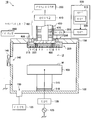
우선, 본 발명의 제 1 실시예에 따른 플라즈마 처리 장치의 전체 구성에 대하여, 도 1을 참조하여 설명한다. 도 1은, 플라즈마 처리 장치를 개략적으로 도시한 종단면도이다.First, the overall configuration of the plasma processing apparatus according to the first embodiment of the present invention will be described with reference to FIG. 1 is a longitudinal sectional view schematically showing a plasma processing apparatus.
본 실시예에서는, 반도체 웨이퍼(W)(이하, 웨이퍼(W)라고 칭호함)에 플라즈마 처리로서 에칭 처리를 실시하는 에칭 장치를 예로 들어 플라즈마 처리 장치(10)를 설명한다. 플라즈마 처리 장치(10)는, 기밀하게 유지된 내부에서 웨이퍼(W)를 플라즈마 처리하는 처리 용기(100)를 가진다. 처리 용기(100)는 원통 형상으로, 예를 들면 알루미늄 등의 금속으로 형성되고, 접지되어 있다.In the present embodiment, the
처리 용기(100)의 저부(底部)에는 웨이퍼(W)를 재치(載置)하는 서셉터(105)가 설치되어 있다. 서셉터(105)는 알루미늄 등의 금속으로 형성되어 있고, 절연체(110)를 개재하여 지지 부재(115)에 의해 지지되고, 처리 용기(100)의 저부에 설치되어 있다. 이에 의해, 서셉터(105)는 전기적으로 부유한 상태가 되어 있다. 서셉터(105) 및 지지 부재(115)의 재료로서는, 표면을 알루마이트 처리(양극 산화 처리)한 알루미늄 등을 들 수 있다.The
서셉터(105)에는, 정합기(120)를 개재하여 바이어스용의 고주파 전원(125)이 접속되어 있다. 고주파 전원(125)은, 서셉터(105)에 바이어스용의 고주파 전력을 인가하고, 이에 의해 웨이퍼(W)측에 플라즈마 중의 이온이 인입된다. 또한 도시하고 있지 않지만, 서셉터(105)에는 웨이퍼(W)를 정전 흡착하기 위한 정전 척, 온도 제어 기구, 웨이퍼(W)의 이면으로 열전달용의 가스를 공급하기 위한 가스 유로, 웨이퍼(W)를 반송할 시 승강하는 승강 핀 등이 설치되어도 된다.The
처리 용기(100)의 저부에는 배기구(130)가 형성되고, 배기구(130)에는 도시하지 않은 진공 펌프를 포함하는 배기 장치(135)가 접속되어 있다. 배기 장치(135)를 작동시키면 처리 용기(100)의 내부가 배기되어, 원하는 진공도까지 감압된다. 처리 용기(100)의 측벽에는 반입출구(140)가 형성되고, 반입출구(140)를 개폐 가능한 게이트 밸브(145)의 개폐에 의해 웨이퍼(W)가 반입출된다.An
서셉터(105)의 상방에는, 가스를 공급하면서, 전자파(여기서는 마이크로파)의 공급이 가능한 플라즈마 발생용 안테나(200)(이하, 안테나(200)라고 함)가 장착되어 있다. 안테나(200)는, 덮개체(150)의 개구 부분에 설치되어 있다. 이에 의해, 서셉터(105)와 안테나(200)의 사이에 플라즈마 공간(U)이 형성된다. 안테나(200)의 상부에는, 마이크로파를 전송하는 전자파 전송 기구로서의 마이크로파 전송 기구(400)가 연결되어, 마이크로파 출력부(300)로부터 출력된 마이크로파를 안테나(200)로 전송하도록 되어 있다.Above the
제어 장치(500)는, 후술하는 바와 같이 안테나(200)에 인가하는 DC 전압 등을 제어한다. 제어 장치(500)는 제어부(505) 및 기억부(510)를 가지고 있다. 제어부(505)는, 기억부(510)에 기억된 레시피에 따라 프로세스마다 안테나(200)에 인가하는 DC 전압을 제어한다. 또한 제어 장치(500)로의 지령은, 전용의 제어 디바이스 혹은 프로그램을 실행하는 CPU(도시하지 않음)에 의해 실행된다. 프로세스 조건을 설정한 레시피는, ROM 또는 불휘발성 메모리(모두 도시하지 않음)에 미리 기억되어 있고, CPU가 이들 메모리로부터 레시피의 조건을 독출하여 실행한다.The
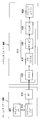
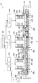
도 2를 참조하여, 마이크로파 출력부(300) 및 마이크로파 전송 기구(400)의 구성에 대하여 설명한다. 도 2의 좌측에는, 마이크로파 출력부(300)의 내부 구성이 나타나 있다. 도 2의 우측에는, 마이크로파 전송 기구(400)의 내부 구성이 나타나 있다.With reference to FIG. 2, the structure of the
마이크로파 출력부(300)는 마이크로파 전원(305), 마이크로파 발진기(310) 및 앰프(315)를 가지고 있다. 마이크로파 전원(305)은 2.45 GHz, 8.35 GHz, 5.8 GHz, 1.98 GHz 등의 주파수의 마이크로파를 출력한다. 마이크로파 전원(305)은 전자파원의 일례이며, 마이크로파대의 전자파를 출력한다. 전자파원은 마이크로파에 한정되지 않고, 100 MHz의 RF대로부터 3 GHz의 마이크로파 대역까지의 전자파를 출력하는 전원이다. 마이크로파 발진기(310)는, 예를 들면 2.45 GHz의 소정 주파수의 마이크로파를 PLL 발진시킨다. 앰프(315)는 발진된 마이크로파를 증폭한다.The
마이크로파 전송 기구(400)는 안테나 모듈(410)과 마이크로파 도입 기구(450)를 가지고 있다. 안테나 모듈(410)은 위상기(412), 가변 게인 앰프(414), 메인 앰프(416) 및 아이솔레이터(418)를 가지고 있어, 마이크로파 출력부(300)로부터 출력된 마이크로파를 마이크로파 도입 기구(450)로 전송한다.The microwave transmission mechanism 400 has an
위상기(412)는, 슬러그 튜너에 의해 마이크로파의 위상을 변화시키도록 구성되고, 이를 조정함으로써 방사 특성을 변조시킬 수 있다. 이에 의하면, 지향성을 제어하여 플라즈마 분포를 변화시킬 수 있다. 또한, 이러한 방사 특성의 변조가 불필요할 경우에는 위상기(412)는 설치할 필요는 없다.The
가변 게인 앰프(414)는, 메인 앰프(416)에 입력하는 마이크로파의 전력 레벨을 조정하고, 플라즈마 강도의 조정을 행한다. 메인 앰프(416)는 솔리드 스테이트 앰프를 구성한다. 솔리드 스테이트 앰프는, 도시하고 있지 않은 입력 정합 회로, 반도체 증폭 소자, 출력 정합 회로 및 고Q공진 회로를 가지는 구성으로 할 수 있다.The
아이솔레이터(418)는, 안테나(200)에서 반사하여 메인 앰프(416)로 돌아오는 마이크로파의 반사파를 분리하는 것이며, 서큘레이터와 더미 로드(동축 종단기)를 가지고 있다. 서큘레이터는, 안테나(200)에서 반사한 마이크로파를 더미 로드로 유도하고, 더미 로드는, 서큘레이터에 의해 유도된 마이크로파의 반사파를 열로 변환한다.The
[플라즈마 발생용 안테나의 구성][Configuration of Plasma Generating Antenna]
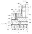
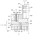
이어서, 제 1 실시예에 따른 마이크로파 도입 기구(450) 및 플라즈마 발생용 안테나(200)의 구성에 대하여 도 3을 참조하여 설명한다. 도 3은, 제 1 실시예에 따른 마이크로파 도입 기구(450) 및 안테나(200)의 확대도(좌측 반)이다.Next, the configuration of the
마이크로파 도입 기구(450)는 동축관(455) 및 지파판(480)을 가지고 있다. 동축관(455)은, 통 형상의 외부 도체(455a) 및 그 중심에 설치된 봉 형상의 내부 도체(455b)로 이루어지는 동축 형상의 도파관을 가지고 있다. 동축관(455)의 하단에는 지파판(480)을 개재하여 안테나(200)가 설치되어 있다. 동축관(455)은 내부 도체(455b)가 급전측, 외부 도체(455a)가 접지측으로 되어 있다. 동축관(455)에는 튜너(470)가 설치되어 있다. 튜너(470)는 2 개의 슬러그(470a)를 가지고, 슬러그 튜너를 구성하고 있다. 슬러그(470a)는 유전 부재의 판상체(板狀體)로서 구성되어 있고, 동축관(455)의 내부 도체(455b)와 외부 도체(455a)의 사이에 원환 형상으로 설치되어 있다. 튜너(470)는, 제어부(505)로부터의 지령에 기초하여, 도시하지 않은 액츄에이터에 의해 슬러그(470a)를 상하 이동시킴으로써, 임피던스를 조정하도록 되어 있다. 제어부(505)는, 예를 들면 동축관(455)의 종단에서 50 Ω의 특성 임피던스가 되도록 임피던스를 조정한다.The
지파판(480)은 동축관(455)의 하면에 인접하여 설치되어 있다. 지파판(480)은 원판 형상의 유전 부재로 형성되어 있다. 지파판(480)은, 동축관(455)으로부터 전송된 마이크로파를 투과하고, 안테나(200)로 유도한다.The
안테나(200)는 샤워 헤드(가스 샤워 헤드)(210) 및 샤워 헤드(210)에 직류 전압을 인가하는 기구(이하, DC 인가 기구(250)라고 칭호함)를 가진다. 샤워 헤드(210)는 지파판(480)의 하면에 인접하여 설치되어 있다. 샤워 헤드(210)는 지파판(480)보다 직경이 큰 원판 형상이며, 알루미늄 또는 구리 등의 전기 전도율이 높은 도전체로 형성되어 있다. 샤워 헤드(210)는 플라즈마 공간(U)측에 노출되고, 노출된 하면에 표면파를 전반시킨다. 여기서는, 샤워 헤드(210)의 금속면이 플라즈마 공간(U)측에 노출되어 있다. 이와 같이 노출된 하면에 전반하는 표면파를 이하, 금속 표면파라고 한다.The
샤워 헤드(210)는 복수의 가스홀(215)과, 이들 가스홀(215)과 분리된 위치에 마이크로파를 통과시키는 복수의 슬롯(220)을 가지고 있다. 샤워 헤드(210)에는, 그 측면을 관통하여, 샤워 헤드(210)의 직경 방향으로 가스 경로(225)가 형성되어 있다. 가스는 가스 공급원(600)(도 1 참조)으로부터 공급되고, 가스 공급관(605)을 통하여 가스 경로(225)로부터 복수의 가스홀(215)로 유입되고, 각 가스홀(215)로부터 처리 용기 내로 도입된다. 샤워 헤드(210)의 플라즈마측에 노출된 면은, 예를 들면 알루미나(Al2O3) 또는 이트리아(Y2O3)의 피막(290)으로 덮어, 도체면이 플라즈마 공간측에 노출되지 않도록 하고 있다. 피막(290)에는, 복수의 슬롯(220) 및 복수의 가스홀(215)에 연통하는 개구가 형성된다.The
샤워 헤드(210)에는 도시하지 않은 냉각로가 형성되어, 샤워 헤드(210)를 냉각하도록 되어 있다. 샤워 헤드(210)는 전기 전도율이 높은 도전체이기 때문에, 마이크로파의 전송 경로인 슬롯(220)으로부터의 열을 효율적으로 처리 용기 본체측으로 방열할 수 있다.The
복수의 슬롯(220)은, 가스의 공급 경로인 가스 경로(225) 및 복수의 가스홀(215)과 분리된 위치에 형성되고, 샤워 헤드(210)의 직경 방향과 수직인 방향으로 관통하고 있다. 슬롯(220)의 일단은 지파판(480)에 인접하고, 타단은 플라즈마 공간(U)측에 개구되어 있다. 마이크로파는 동축관(455)을 전송하고, 지파판(480)을 투과한 다음, 복수의 슬롯(220)에 통과되어 플라즈마 공간(U)에 방사된다.The plurality of
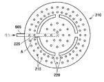
도 4는, 샤워 헤드(210)의 플라즈마 공간(U)에 노출된 면(하면)을 도시한 도이다. 복수의 가스홀(215)이 대략 균등하게 배치되어 있다. 가스홀(215)은, 대략 링 형상의 슬롯(220)의 외주측 및 내주측에 형성되어 있다. 슬롯(220)은 완전한 링 형상으로는 형성되어 있지 않고, 4 개로 구획된 부채꼴 형상으로 되어 있다. 슬롯(220)이 구획된 부분(A)에는, 가스 경로(225)가 슬롯(220)과 연통하지 않도록 형성되고, 슬롯(220)의 내주측에 형성된 가스홀(215)로 가스를 공급하도록 되어 있다. 따라서, 슬롯(220)에는, 가스 경로(225)를 통과시키기 위한 구획이 적어도 하나 필요하다. 따라서 본 실시예에서는, 슬롯(220)은 4 개이지만 이에 한정되지 않고, 적어도 하나 이상의 구획 부분을 가지고 있으면 된다.4 is a diagram illustrating a surface (lower surface) exposed to the plasma space U of the
복수의 슬롯(220)은, 안테나(200)의 중심축(도 3의 중심축(O))에 대하여 축대칭으로 형성되어 있다. 이에 의해, 슬롯(220)으로부터 보다 균일하게 마이크로파를 방사할 수 있다.The plurality of
가스홀(215)은, 플라즈마 공간(U)에 방사된 마이크로파가 이 가스홀(215)의 내부에 혼입되지 않도록 좁은 홀로 되어 있다. 또한, 슬롯(220)과 가스홀(215)은 샤워 헤드(210) 내에서 완전히 분리되어 있다. 이에 의해, 가스 경로(225) 및 가스홀(215)에서의 이상 방전을 방지할 수 있다.The
다시 도 3으로 돌아와, 지파판(480)과 샤워 헤드(210)의 접촉면에는 O링(485) 및 O링(495)이 설치되어, 대기측에 설치된 마이크로파 전송 기구(400)로부터 샤워 헤드(210) 및 처리 용기(100)의 내부를 진공 씰링하고 있다. 이에 의해, 플라즈마 공간(U), 슬롯(220), 가스 경로(225), 가스홀(215)의 내부를 진공 상태로 할 수 있다.3 again, the O-
본 실시예와 같이, 샤워 헤드(210)가 도전체일 경우에는, 샤워 헤드(210)에 DC 전압(직류 전압)을 인가할 수 있다. 구체적으로, 제어부(505)의 지령에 따라, DC전원(255)으로부터 출력된 DC 전압은 DC 인가 기구(250)로 공급된다. DC 인가 기구(250)는 DC 전극(260), 절연 부재(265) 및 절연 시트(270)를 가진다. DC 전극(260)은 통 형상의 도전체(260a)를 가지고, 통 형상의 도전체(260a)를 개재하여 샤워 헤드(210)에 접속되고, 이에 의해 샤워 헤드(210)에 DC 전압을 인가한다. DC 전극(260)은, 통 형상의 도전체(260a)의 하단에 설치된 도시하지 않은 절연 소켓에 의해 샤워 헤드(210)에 나사 고정되어 있다.As in the present embodiment, when the
DC 전극(260)은 동축관(455)의 외부 도체(455a) 및 덮개체(150)에 근접하고 있다. 따라서, DC 전극(260)과 동축관(455) 및 DC 전극(260)과 덮개체(150)를 DC적으로 절연하기 위하여 DC 전극(260)을 절연 부재(265)로 덮고, DC 전극(260)과 동축관(455) 및 DC 전극(260)과 덮개체(150)를 절연한다. 또한, 샤워 헤드(210)와 동축관(455) 및 샤워 헤드(210)와 덮개체(150)를 DC적으로 절연하기 위하여, 샤워 헤드(210)와 동축관(455)의 사이, 및 샤워 헤드(210)와 덮개체(150)의 사이에 절연 시트(270)를 개재한다. 이와 같이 하여, 처리 용기(100)를 DC적으로 절연함으로써, DC 전압이 샤워 헤드(210)에만 인가되어, DC 전압이 걸리는 부재를 가능한 한 줄일 수 있다. 또한, 샤워 헤드(210)가 절연체로 형성되어 있을 경우에는, DC 전압을 샤워 헤드(210)에 인가할 수는 없다. 단 이 경우, RF 전압을 인가하면 동일한 효과를 기대할 수 있다.The
이상에 설명한 바와 같이, 본 실시예에 따른 플라즈마 처리 장치(10)에 의하면, 동축관(455)으로부터 도입된 마이크로파는 지파판(480)을 통과하고, 샤워 헤드(210)를 관통하여 형성된 복수의 슬롯(220)을 통하여 플라즈마 공간(U)에 방사된다. 이 때, 샤워 헤드(210)의 표면에는 플라즈마 시스를 경계 조건으로 하여 분산 관계로 특징지어지는 파장을 가진 정재파(금속 표면파)가 발생하고, 표면파 플라즈마에 흡수된다. 가스 공급원(600)으로부터 공급된 가스도 또한, 샤워 헤드(210)를 통하여 플라즈마 공간(U)으로 도입된다. 도입된 가스는 표면파 플라즈마에 의해 여기된다. 이에 의해, 처리 용기(100) 내의 플라즈마 공간(U)에 저전자 온도 또한 고플라즈마 밀도인 플라즈마가 생성된다. 생성된 플라즈마는 웨이퍼(W)의 에칭 처리에 사용된다. 플라즈마는 저전자 온도이기 때문에 웨이퍼(W)는 데미지를 받기 어렵고, 또한 고플라즈마 밀도이기 때문에 웨이퍼(W)에 고속으로 미세 가공을 실시할 수 있다. 또한, 샤워 헤드(210)를 도전체로 형성함으로써, 반응성 에칭 등의 프로세스를 실행할 수 있다.As described above, according to the
일반적인 표면파 플라즈마원일 경우, 안테나 슬롯의 하부에는 유전체가 설치되고, 유전체로 샤워 헤드 구조를 제작할 경우, 전자파는 유전체를 투과하기 때문에 그 내부에서 이상 방전이 발생할 가능성이 높아져, 일반적인 표면파 플라즈마원에서 샤워 헤드 구조를 채용하는 것은 매우 곤란했다. 예를 들면, 아르곤 플라즈마에서 샤워 헤드 공간 내에 10 mm의 공간이 비어 있을 경우, 그 거리를 따라 약 120 볼트의 전압이 샤워 헤드 내부에 발생하면, 압력 1 Torr로 샤워 헤드 내부에서 이상 방전이 발생할 가능성이 높아진다.In the case of a general surface wave plasma source, a dielectric is installed in the lower part of the antenna slot, and when a shower head structure is fabricated from the dielectric, electromagnetic waves penetrate through the dielectric, so that there is a high possibility of abnormal discharges therein. It was very difficult to adopt the structure. For example, in an argon plasma, if a space of 10 mm is empty in the shower head space, if a voltage of about 120 volts is generated inside the shower head along the distance, abnormal discharge may occur inside the shower head at a pressure of 1 Torr. Is higher.
이에 대하여, 본 실시예에 따른 플라즈마 처리 장치(10)는 샤워 헤드(210)가 금속 등의 도전체로 되어 있기 때문에, 샤워 헤드(210) 내부에 전자파는 진입하지 않고, 샤워 헤드(210) 내부의 전계는 없는 것과 마찬가지이다. 이 때문에, 이상 방전은 발생하지 않는다. 전자파와 가스는 샤워 헤드(210) 내부에서 격리되어 있고, 처리 용기(100) 내에 유입되어 처음으로 이들은 접촉한다. 그러므로, 본 실시예에 따른 플라즈마 처리 장치(10)를 이용함으로써, 샤워 헤드(210)로 균일하게 가스를 방출시키면서, 이상 방전없이 표면파 플라즈마를 생성할 수 있다.On the other hand, in the
또한, 본 실시예에 따른 플라즈마 처리 장치(10)에 의하면, 샤워 헤드(210)에 DC 전압을 인가하면서, 동일한 샤워 헤드(210)에 마이크로파를 인가할 수 있다. 이에 의해, 플라즈마 처리 장치(10)를 다양한 프로세스에 적용할 수 있다. 예를 들면, 마이크로파가 인가되면 샤워 헤드(210)의 표면에 표면파가 전반한다. 이 때, 샤워 헤드(210)의 표면에는 시스 영역이 발생하고, 시스 중을 표면파가 전반한다. DC 전압은 그 시스의 두께를 제어한다. 예를 들면, DC 전압을 샤워 헤드(210)에 인가하면 시스를 두껍게 제어할 수 있고, 그 결과, 샤워 헤드(210)의 표면을 전반하는 표면파의 전반 거리를 길게 할 수 있다. 이와 같이 DC 전압의 제어에 의해 플라즈마 시스 전압을 조작함으로써, 표면파의 전반 거리를 제어하고, 플라즈마의 전자 밀도 분포, 라디칼 밀도 분포를 최적화할 수 있다.In addition, according to the
[슬롯의 변형예][Modification of slots]
안테나(200)에 형성되는 슬롯의 변형예에 대하여 도 5를 참조하여 설명한다. 도 5의 상측, 중앙, 하측에는 각각 상이한 형상의 슬롯(220)이 도시되어 있다. 도 5의 상측의 슬롯은 6 개의 슬롯(220)으로 구획되어 있다. 각 슬롯(220)은 중앙에서 두껍고 양 단부가 얇은 동일 형상이다. 인접하는 슬롯(220)의 양 단부는 서로 대향하고 있다.A modification of the slot formed in the
도 5의 중앙의 슬롯은 6개의 슬롯(220)으로 구획되어 있다. 각 슬롯(220)의 중앙은 양 단부와 동일한 두께이다. 각 슬롯(220)은 약간 만곡하여 경사 방향으로 기운 동일 형상이다. 인접하는 슬롯(220)의 양 단부는 서로 대향하고 있다.The center slot of FIG. 5 is divided into six
도 5의 하측의 슬롯은, 외주측이 4 개의 슬롯(220)으로 구획되고, 내주측도 4 개의 슬롯(220)으로 구획된 2 단의 슬롯 구조로 되어 있다. 각 슬롯(220)은 동일한 두께의 원호 형상이며, 동일 형상이다. 외주측의 슬롯(220) 간의 구획이 내주측의 슬롯(220)의 중앙에 위치하고, 내주측의 슬롯(220) 간의 구획이 외주측의 슬롯(220)의 중앙에 위치하도록 배치되어 있다.In the lower slot of FIG. 5, the outer circumferential side is divided into four
모든 변형예에서, 복수의 슬롯(220)은 안테나(200)의 중심축에 대하여 축대칭으로 형성되어 있다. 이에 의해, 마이크로파를 처리 용기(100) 내에 균일하게 방사할 수 있다. 또한, 복수의 슬롯(220)은 적어도 1 개 이상의 구획 부분을 가지고 있다. 이에 의해, 슬롯(220)의 외주측 및 내주측에 형성된 도시하지 않은 가스홀(215)로부터 가스를 공급할 수 있다.In all variations, the plurality of
<제 2 실시예>≪ Embodiment 2 >
[플라즈마 발생용 안테나의 구성][Configuration of Plasma Generating Antenna]
이어서, 제 2 실시예에 따른 플라즈마 발생용 안테나의 구성에 대하여 도 6을 참조하여 설명한다. 도 6은, 제 2 실시예에 따른 플라즈마 발생용 안테나(200)의 확대도(좌측 반)이다. 제 2 실시예에 따른 플라즈마 발생용 안테나(200)는, 제 1 실시예에 따른 안테나 대신에 도 1의 플라즈마 처리 장치(10)의 안테나 부분에 적용될 수 있다.Next, a configuration of a plasma generating antenna according to the second embodiment will be described with reference to FIG. 6. 6 is an enlarged view (left half) of the
제 2 실시예에 따른 복수의 슬롯(220)에는 유전 부재(220a)가 충전되어 있다. 유전 부재(220a)로서는 석영 등을 이용해도 된다. 이에 의해, 슬롯(220) 내로 플라즈마가 진입하는 것을 방지할 수 있다.The
제 2 실시예에서는, 예를 들면 알루미늄으로 형성된 샤워 헤드(210)의 플라즈마 공간측의 노출면에는 실리콘의 천판(700)이 고정되어 있다. 이에 의해, 플라즈마에 의해 데미지를 받은 천판(700)을 교환할 수 있어, 샤워 헤드(210)의 수명을 연장시킬 수 있다. 천판(700)에는, 복수의 슬롯(220) 및 복수의 가스홀(215)에 연통하는 개구가 형성된다. 슬롯(220)과 연통하는 개구에는 슬롯(220)과 마찬가지로 유전 부재(220a)가 충전된다.In the second embodiment, the
<변형예><Variation example>
상기 실시예의 변형예로서, 샤워 헤드(210)가 실리콘으로 형성되어 있을 경우를 든다. 이 경우에는, 샤워 헤드(210)에 용사를 실시하거나 천판(700)을 설치하지 않고, 도 7에 도시한 바와 같이 그대로 샤워 헤드(210)의 실리콘 표면을 노출한다.As a modification of the above embodiment, the
제 2 실시예 및 변형예의 경우에도, 샤워 헤드(210)에 DC 전압을 인가하면서, 동일한 샤워 헤드(210)에 마이크로파를 인가할 수 있다. 이에 의해, 플라즈마 처리 장치(10)를 다양한 프로세스에 적용할 수 있다. 예를 들면, 마이크로파가 인가되면, 샤워 헤드(210)의 표면에 표면파가 전반한다. 이 때, 샤워 헤드(210)의 표면에는 시스 영역이 발생하고, 시스 중을 표면파가 전반한다. DC 전압은 이 시스의 두께를 제어한다. 예를 들면, DC 전압을 샤워 헤드(210)에 인가하면 시스를 두껍게 제어할 수 있고, 그 결과, 샤워 헤드(210)의 표면을 전반하는 표면파의 전반 거리를 길게 할 수 있다. 이와 같이, DC 전압의 제어에 의해 플라즈마 시스 전압을 조작함으로써, 표면파의 전반 거리를 제어하고, 플라즈마의 전자 온도를 최적화할 수 있다. 또한 변형예의 경우에는, DC 전압을 샤워 헤드(210)에 인가하면 샤워 헤드(210)로부터 실리콘을 축출하여, 이에 의해 에칭의 선택비를 높이는 것도 가능해진다.In the second embodiment and the modified example, microwaves may be applied to the
플라즈마 생성 시의 가스 종류, 압력 및 고주파 전력의 크기에 따라서는, 슬롯(220)의 근방에 플라즈마가 과도하게 집중하고, 플라즈마의 균일성을 흩뜨릴 우려가 있다. 하지만 이상에 설명한 바와 같이, 본 실시예에 따른 플라즈마 처리 장치(10)에 의하면, 슬롯(220)의 내부에 유전 부재(220a)가 충전되어 있다. 이 때문에, 슬롯(220) 내로 플라즈마가 진입하는 것을 방지할 수 있다. 이에 의해, 플라즈마의 균일성을 높일 수 있다. 또한, 슬롯(220) 내의 유전 부재(220a)에 의해, 슬롯 내를 통과하는 마이크로파의 실효적인 파장을 짧게 할 수 있다. 이에 따라, 샤워 헤드(210)의 두께를 얇게 할 수 있다.Depending on the type of gas, pressure, and high frequency power during plasma generation, there is a fear that the plasma is excessively concentrated in the vicinity of the
<제 3 실시예>Third Embodiment
[플라즈마 발생용 안테나의 구성][Configuration of Plasma Generating Antenna]
이어서, 제 3 실시예에 따른 플라즈마 발생용 안테나의 구성에 대하여, 도 8을 참조하여 설명한다. 도 8은, 제 3 실시예에 따른 플라즈마 발생용 안테나의 확대도(좌측 반)이다. 제 3 실시예에 따른 플라즈마 발생용 안테나(200)는, 제 1 실시예에 따른 안테나 대신에 도 1의 플라즈마 처리 장치(10)의 안테나 부분에 적용될 수 있다.Next, a configuration of the plasma generating antenna according to the third embodiment will be described with reference to FIG. 8. 8 is an enlarged view (left half) of the antenna for plasma generation according to the third embodiment. The
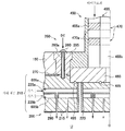
제 3 실시예에 따른 샤워 헤드(210)의 가스 경로는, 제 1 가스 경로(225a) 및 제 2 가스 경로(225b)로 나누어져 있다. 제 1 가스 경로(225a) 및 제 2 가스 경로(225b)는 완전히 분리되어 있다. 제 1 가스 경로(225a)는 가스 공급관(605a)에 접속되어 있다. 또한, 제 2 가스 경로(225b)는 가스 공급관(605b)에 접속되어 있다. 원하는 가스(1)는 가스 공급원(600)(도 1 참조)으로부터 공급되고, 가스 공급관(605a)을 통하여 가스 경로(225a)로부터 복수의 가스홀(215)로 유입되고, 각 가스홀(215)로부터 처리 용기 내로 도입된다. 원하는 가스(2)는 가스 공급원(600)(도 1 참조)으로부터 공급되고, 가스 공급관(605b)을 통하여 가스 경로(225b)로부터 다른 복수의 가스홀(215)로 유입되고, 각 가스홀(215)로부터 처리 용기 내로 도입된다. 이에 의해, 인접하는 가스홀로부터 상이한 종류의 가스를 교호로 도입할 수 있다.The gas path of the
이상에 설명한 바와 같이, 본 실시예에 따른 플라즈마 처리 장치(10)에 의하면, 샤워 헤드(210) 중에 독립한 2 개의 샤워 헤드 공간(매트릭스 샤워)이 형성되고, 이에 의해 2 계통의 가스의 흐름을 제어한다. 가스는, 각 샤워 헤드로부터 처리 용기(100)로 공급되고, 처리 용기 내의 공간에서 혼합되어, 2 종류 이상의 가스를 반응시킬 수 있다(포스트 믹스). 이에 의하면, 가스 종류에 따라 가스의 도입 위치를 최적화할 수 있어, 원하는 플라즈마를 생성할 수 있다. 또한 가스 경로는, 2 계통에 한정되지 않고, 3 종류 이상의 가스를 혼합하지 않고 별도로 공급 가능한 3 계통 이상의 가스 경로로 나누어져 있어도 된다.As described above, according to the
<제 4 실시예><Fourth Embodiment>
[플라즈마 발생용 안테나의 구성][Configuration of Plasma Generating Antenna]
이어서, 제 4 실시예에 따른 플라즈마 발생용 안테나의 구성에 대하여, 도 9 및 도 10을 참조하여 설명한다. 도 9는, 제 4 실시예에 따른 플라즈마 처리 장치의 안테나 부분을 도시한 도이다. 도 9에서는, 안테나(200)보다 하측의 부분을 생략하고 있는데, 제 4 실시예에 따른 플라즈마 처리 장치(10)는 제 1 실시예에 따른 플라즈마 처리 장치와 동일한 구성이다. 도 10은, 마이크로파 출력부(300) 및 마이크로파 전송 기구(400)의 구성을 나타낸 도이다.Next, a configuration of the antenna for generating plasma according to the fourth embodiment will be described with reference to FIGS. 9 and 10. 9 is a diagram showing an antenna portion of the plasma processing apparatus according to the fourth embodiment. In FIG. 9, a portion below the
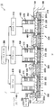
제 4 실시예에 따른 플라즈마 처리 장치(10)에서는, 3 개의 안테나(200)가 덮개체(150)에 설치되어 있다. 각 안테나(200)의 기본적 구조는 제 1 실시예에서 설명했으므로 여기서는 설명을 생략한다.In the
제 4 실시예에 따른 플라즈마 처리 장치(10)에서는, 마이크로파는, 도 10의 마이크로파 출력부(300) 내에 나타낸 마이크로파 전원(305)으로부터 출력되고, 마이크로파 발진기(310) 및 앰프(315)를 거쳐 분배기(320)에서 분배된다.In the
구체적으로, 마이크로파 발진기(310)는 예를 들면 2.45 GHz의 소정 주파수의 마이크로파를 PLL 발진시킨다. 앰프(315)는 발진된 마이크로파를 증폭한다. 분배기(320)는 증폭된 마이크로파를 복수로 분배한다. 분배기(320)에서는, 마이크로파가 가능한 한 손실되지 않도록, 입력측과 출력측의 임피던스 정합을 취하면서 앰프(315)에서 증폭된 마이크로파를 분배한다. 분배된 마이크로파는 각 안테나 모듈(410)로 전송된다.Specifically, the
본 실시예에서는 마이크로파 전송 기구(400)는, 분배기(320)에서 분배된 마이크로파를 전송하는 3 개의 안테나 모듈(410)을 가지고 있다. 각 안테나 모듈(410)은, 마이크로파를 각 안테나 모듈(410)에 접속된 동축관(455)으로부터 처리 용기(100) 내에 방사하고, 그 내부에서 마이크로파를 공간 합성한다. 따라서, 아이솔레이터(418)는 소형인 것으로 좋고, 메인 앰프(416)에 인접하여 설치할 수 있다.In the present embodiment, the microwave transmission mechanism 400 has three
각 안테나 모듈(410)의 위상기(412)는, 슬러그 튜너에 의해 마이크로파의 위상을 변화시키도록 구성되고, 이를 조정함으로써 방사 특성을 변조시킬 수 있다. 예를 들면, 안테나 모듈(410)마다 위상을 조정함으로써, 지향성을 제어하여 플라즈마 분포를 변화시키는 것, 또는 이웃하는 안테나 모듈(410)에서 90°씩 위상을 어긋나게 하여 원편파를 얻을 수 있다. 또한, 이러한 방사 특성의 변조가 불필요할 경우에는 위상기(412)는 설치할 필요는 없다.The
가변 게인 앰프(414)는, 메인 앰프(416)에 입력하는 마이크로파의 전력 레벨을 조정하고, 개개의 안테나 모듈(410)의 격차의 조정 및 플라즈마 강도의 조정을 행한다. 가변 게인 앰프(414)를 안테나 모듈(410)마다 변화시킴으로써, 발생하는 플라즈마에 분포를 발생시킬 수도 있다.The
메인 앰프(416)는 솔리드 스테이트 앰프를 구성한다. 솔리드 스테이트 앰프는, 도시하고 있지 않은 입력 정합 회로, 반도체 증폭 소자, 출력 정합 회로 및 고Q공진 회로를 가지는 구성으로 할 수 있다.The
아이솔레이터(418)는, 안테나(200)에서 반사하여 메인 앰프(416)를 향하는 마이크로파의 반사파를 분리하는 것이며, 서큘레이터와 더미 로드(동축 종단기)를 가지고 있다. 서큘레이터는, 안테나(200)에서 반사한 마이크로파를 더미 로드로 유도하고, 더미 로드는 서큘레이터에 의해 유도된 마이크로파의 반사파를 열로 변환한다. 안테나 모듈(410)로부터 출력된 마이크로파는, 마이크로파 도입 기구(450)로 전송되고, 안테나(200)로 유도된다.The
또한, 본 실시예에서는, 3 개의 안테나(200)를 덮개체(150)에 개별적으로 설치하고, 각각에 가스 공급관(605)을 형성하고 있었지만, 즉 각 안테나(200)마다 독립적으로 샤워 헤드(210)가 설치되어 있었지만, 복수의 샤워 헤드(210)를 덮개체(150)에 설치하는 것보다, 복수의 안테나(200)에 대하여 1 개의 샤워 헤드(210)를 설치하는 것이 제작이 용이하다. 따라서 본 실시예의 변형예로서, 예를 들면 도 11에 도시한 바와 같이, 3 개의 안테나(200)에 대하여 1 개의 샤워 헤드(210)를 공통으로 설치해도 된다. 이러한 경우, 공통의 샤워 헤드(210)에 대하여 가스 공급관(605)이 1 개 형성된다. 또한 도 11에서, 각 안테나(200)의 기본적 구조는, 샤워 헤드(210)와 가스 공급관(605)이 복수의 안테나(200)에 대하여 공통화되어 있는 점을 제외하고, 도 9에 도시한 경우와 동일하다.In addition, in the present embodiment, three
또한, 복수의 안테나(200)를 1 개의 샤워 헤드(210)에 공통적으로 설치할 경우, 예를 들면 각각 독립한 환상의 가스 경로(225)를 덮개체(150)의 중심축을 중심으로 하여 동심원 형상으로 형성해도 된다. 이러한 경우, 각 가스 경로(225)는 서로 격리된다. 구체적으로, 예를 들면 도 12에 도시한 바와 같이, 샤워 헤드(210)에 내외 2 계통의 환상의 가스 경로(225c, 225d)를 형성한다. 각각의 가스 경로(225c, 225d)에는 가스 공급관(605)이 각각 형성된다. 이와 같이 함으로써, 플라즈마 공간(U)에 도입되는 가스의 유속 및 도입되는 가스의 종류를, 샤워 헤드(210)의 중심측의 영역과 외측의 영역에서 각각 상이한 것으로 할 수 있다. In addition, when a plurality of
[플라즈마 발생용 안테나의 동작][Operation of Plasma Generating Antenna]
마지막으로, 제 1 ~ 제 4 실시예에 따른 플라즈마 처리 장치(10)의 동작에 대하여, 도 1을 참조하여 설명한다. 우선, 웨이퍼(W)를 처리 용기(100) 내로 반입하고, 서셉터(105) 상에 재치한다. 그리고, 예를 들면 Ar 가스 등의 플라즈마 가스는 가스 공급원(600)으로부터 공급되고, 가스 공급관(605)을 통하여 안테나(200)로부터 처리 용기(100) 내로 도입된다. 마이크로파는, 마이크로파 출력부(300)로부터 출력되고, 마이크로파 전송 기구(400) 및 지파판(480), 슬롯(220)을 통하여 처리 용기(100) 내로 도입된다. 마이크로파의 전계 에너지에 의해 플라즈마 가스가 여기되어, 플라즈마가 생성된다.Finally, the operation of the
이어서, 예를 들면 Cl2 가스 등의 에칭 가스가 가스 공급원(600)으로부터 공급되고, 복수로 분기된 가스 공급관(605)을 통하여 안테나(200)로부터 처리 용기(100) 내로 도입된다. 에칭 가스는 마찬가지로 여기되어 플라즈마화한다. 이와 같이 하여 형성된 처리 가스의 플라즈마에 의해, 웨이퍼(W)에 예를 들면 에칭 처리가 실시된다. 플라즈마는 저전자 온도이기 때문에 웨이퍼(W)는 데미지를 받지 않고, 또한 고플라즈마 밀도이기 때문에 웨이퍼(W)에 고속으로 미세 가공을 실시할 수 있다.Subsequently, an etching gas such as, for example, Cl 2 gas is supplied from the
특히, 제 4 실시예에 따른 플라즈마 처리 장치(10)에서는, 마이크로파 발진기(310)로부터 발진된 마이크로파는, 앰프(315)에서 증폭된 다음 분배기(320)에 의해 복수로 분배된다. 분배된 마이크로파는 복수의 안테나 모듈(410)로 유도된다. 각 안테나 모듈(410)에서 이와 같이 복수로 분배된 마이크로파는, 솔리드 스테이트 앰프를 구성하는 메인 앰프(416)에서 개별적으로 증폭하고, 각 마이크로파 도입 기구(450)로 전송된다. 각 마이크로파 도입 기구(450)에서는, 동축관(455)을 이용하여 마이크로파가 지파판(480)으로 전송된다. 지파판(480)을 투과한 마이크로파는, 각 샤워 헤드(210)의 슬롯(220)으로부터 처리 용기 내에 방사된다.In particular, in the
이상 각 실시예에 의하면, 가스 및 전자파를 분리하여 공급 가능한 플라즈마 발생용 안테나(200) 및 플라즈마 처리 장치(10)를 제공할 수 있다.According to the above embodiments, it is possible to provide a
이상, 첨부 도면을 참조하여 본 발명의 적합한 실시예에 대하여 상세히 설명했지만, 본 발명은 이러한 예에 한정되지 않는다. 본 발명이 속하는 기술의 분야에서의 통상의 지식을 가지는 자라면, 특허 청구의 범위에 기재된 기술적 사상의 범주에서, 각종의 변경예 또는 수정예에 상도할 수 있는 것은 명백하고, 이들에 대해서도 당연히 본 발명의 기술적 범위에 속하는 것으로 이해된다.As mentioned above, although the preferred embodiment of this invention was described in detail with reference to an accompanying drawing, this invention is not limited to this example. Those skilled in the art to which the present invention pertains can clearly conceive of various modifications or modifications within the scope of the technical idea described in the claims. It is understood to belong to the technical scope of the invention.
예를 들면, 상기 실시예에서는 플라즈마 처리 장치 내에서 실행되는 플라즈마 처리로서 에칭 처리를 예로 들어 설명했지만, 본 발명은 이러한 예에 한정되지 않는다. 예를 들면, 본 발명에 따른 플라즈마 처리 장치는 성막 및 애싱 등 모든 플라즈마 처리를 실행 가능하다.For example, in the above embodiment, the etching process has been described as an example of the plasma process performed in the plasma processing apparatus, but the present invention is not limited to this example. For example, the plasma processing apparatus according to the present invention can perform all plasma processing such as film formation and ashing.
또한, 본 발명에 따른 플라즈마 발생용 안테나는, 상기 실시예에 도시한 마이크로파 플라즈마 처리 장치에 한정되지 않고, 유도 결합형(ICP(Inductively Coupled Plasma))의 플라즈마 처리 장치, 용량 결합형의 플라즈마 처리 장치 등 모든 플라즈마 처리 장치에 사용할 수 있다. 그리고, 본 발명에 따른 플라즈마 처리 장치는, 표면파 플라즈마를 사용하는 프로세스, ICP 플라즈마를 사용하는 프로세스, CCP 플라즈마를 사용하는 프로세스에 적용 가능하다.The plasma generating antenna according to the present invention is not limited to the microwave plasma processing apparatus shown in the above embodiments, but is an inductively coupled plasma processing apparatus (ICP (Inductively Coupled Plasma)) or a capacitively coupled plasma processing apparatus. Etc. can be used for all plasma processing apparatus. The plasma processing apparatus according to the present invention is applicable to a process using surface wave plasma, a process using ICP plasma, and a process using CCP plasma.
또한 각 실시예에서는, 플라즈마 처리 장치에 장착된 플라즈마 발생용 안테나는 1 개 또는 3 개였다. 그러나, 본 발명에 따른 플라즈마 처리 장치에 장착하는 플라즈마 발생용 안테나의 수는 이에 한정되지 않고, 2 개 또는 4 개 또는 그 이상이어도 된다. 단, 웨이퍼(W)를 이온에 의해 때리는 공정을 포함하는 프로세스일 경우에는, 복수의 플라즈마 발생용 안테나를 가진 플라즈마 처리 장치가 바람직하다. 한편, 웨이퍼(W)를 라디칼로 반응시키는 프로세스일 경우에는, 1 개의 플라즈마 발생용 안테나를 가진 플라즈마 처리 장치가 바람직하다.In each of the embodiments, one or three plasma generating antennas mounted on the plasma processing apparatus were used. However, the number of plasma generating antennas to be mounted on the plasma processing apparatus according to the present invention is not limited to this, and may be two or four or more. However, in the case of a process including a step of striking the wafer W with ions, a plasma processing apparatus having a plurality of plasma generating antennas is preferable. On the other hand, in the case of the process of reacting the wafer W with radicals, a plasma processing apparatus having one antenna for generating plasma is preferable.
또한, 본 발명에 따른 플라즈마 처리 장치의 처리 용기는, 원통 형상에 한정되지 않고, 예를 들면 6 각형 또는 4 각형이어도 된다. 따라서, 본 발명에 따른 플라즈마 처리 장치에서 처리되는 피처리체는, 원반 형상의 반도체 웨이퍼에 한정되지 않고, 예를 들면 직사각형의 기판이어도 된다.In addition, the processing container of the plasma processing apparatus which concerns on this invention is not limited to a cylindrical shape, For example, a hexagonal shape or a square shape may be sufficient. Therefore, the to-be-processed object processed by the plasma processing apparatus which concerns on this invention is not limited to a disk shaped semiconductor wafer, For example, a rectangular substrate may be sufficient as it.
10 : 플라즈마 처리 장치
100 : 처리 용기
105 : 서셉터
150 : 덮개체
200 : 플라즈마 발생용 안테나
210 : 샤워 헤드
215 : 가스홀
220 : 슬롯
225 : 가스 경로
225a : 제 1 가스 경로
225b : 제 2 가스 경로
250 : DC 인가 기구
255 : DC 전원
260 : DC 전극
300 : 마이크로파 출력부
400 : 마이크로파 전송 기구
410 : 안테나 모듈
450 : 마이크로파 도입 기구
455 : 동축관
455a : 외부 도체
455b : 내부 도체
480 : 지파판
500 : 제어 장치
505 : 제어부
600 : 가스 공급원
U : 플라즈마 공간10: Plasma processing device
100 processing container
105: susceptor
150: cover body
200: antenna for plasma generation
210: Shower Head
215: gas hole
220: slot
225: gas path
225a: first gas path
225b: second gas path
250: DC approval mechanism
255: DC power
260 DC electrode
300: microwave output unit
400: microwave transmission mechanism
410: antenna module
450: microwave introduction mechanism
455: coaxial tube
455a: outer conductor
455b: inner conductor
480: slow wave plate
500 control device
505: control unit
600: gas source
U: plasma space
Claims (15)
공급된 전자파를 투과하는 지파판과,
상기 지파판에 인접하여 설치된 샤워 헤드를 가지는 플라즈마 발생용 안테나
를 구비하고,
상기 샤워 헤드는 도전체로 형성되고, 복수의 가스홀이 형성되고, 상기 복수의 가스홀과 분리된 위치에 전자파를 통과시키는 복수의 슬롯을 가지는 것을 특징으로 하는
플라즈마 처리 장치.A processing vessel in which plasma processing is performed,
A slow wave plate that transmits the supplied electromagnetic waves,
Plasma generating antenna having a shower head provided adjacent to the slow wave plate
And,
The shower head is formed of a conductor, a plurality of gas holes are formed, and has a plurality of slots for passing electromagnetic waves in a position separated from the plurality of gas holes
Plasma processing apparatus.
상기 플라즈마 처리 장치는 복수의 상기 플라즈마 발생용 안테나를 구비하는 것을 특징으로 하는 플라즈마 처리 장치.The method of claim 1,
And said plasma processing apparatus comprises a plurality of said plasma generating antennas.
상기 샤워 헤드는 플라즈마 공간측으로 노출된 면에 표면파를 전반시키는 것을 특징으로 하는 플라즈마 처리 장치.The method of claim 2,
And the shower head propagates a surface wave to a surface exposed to the plasma space side.
상기 샤워 헤드에는, 상기 복수의 슬롯의 내측 및 외측에 상기 복수의 가스홀이 형성되어 있는 플라즈마 처리 장치.The method of claim 3, wherein
And the plurality of gas holes are formed in the shower head at the inside and the outside of the plurality of slots.
상기 복수의 슬롯을 구획하는 부분을 통과하고, 상기 슬롯보다 내측에 형성된 복수의 가스홀로 가스를 공급하는 가스 경로를 더 구비한 것을 특징으로 하는 플라즈마 처리 장치.The method of claim 4, wherein
And a gas path passing through a portion partitioning the plurality of slots and supplying gas to a plurality of gas holes formed inside the slot.
상기 가스 경로는 복수의 가스를 별도로 공급 가능한 복수의 가스 경로로 나뉘어 형성되는 플라즈마 처리 장치.The method of claim 5, wherein
The gas path is formed by dividing the gas path into a plurality of gas paths that can be supplied separately.
상기 가스 경로는 상기 샤워 헤드의 중심축에 대하여 동심원 형상으로 형성되는 플라즈마 처리 장치.The method according to claim 6,
And the gas path is formed concentrically with respect to the central axis of the shower head.
복수의 상기 플라즈마 발생용 안테나에는 상기 표면파의 전력을 조정하는 전자파 전송 기구가 각각 설치되어 있는 플라즈마 처리 장치.8. The method according to any one of claims 3 to 7,
And a plurality of said plasma generating antennas are each provided with an electromagnetic wave transmission mechanism for adjusting the electric power of said surface wave.
상기 샤워 헤드에 직류 전압을 인가하는 기구를 더 구비한 것을 특징으로 하는 플라즈마 처리 장치.The method according to any one of claims 1 to 7,
And a mechanism for applying a DC voltage to the shower head.
상기 샤워 헤드에 직류 전압을 인가하는 기구는 상기 동축관과의 사이에 절연 부재를 가지는 것을 특징으로 하는 플라즈마 처리 장치.The method of claim 9,
A mechanism for applying a DC voltage to the shower head has an insulating member between the coaxial tube and the plasma processing apparatus.
상기 복수의 슬롯에는 유전 부재가 충전되어 있는 것을 특징으로 하는 플라즈마 처리 장치.The method according to any one of claims 1 to 7,
And the dielectric member is filled in the plurality of slots.
상기 복수의 슬롯은, 상기 플라즈마 발생용 안테나의 중심축에 대하여 축대칭으로 형성되어 있는 것을 특징으로 하는 플라즈마 처리 장치.The method according to any one of claims 1 to 7,
And the plurality of slots are formed in axisymmetric with respect to a central axis of the plasma generating antenna.
상기 샤워 헤드의 표면에는 용사가 실시되거나 또는 천판이 고정되고, 상기 복수의 슬롯 및 상기 복수의 가스홀에 연통하는 개구가 형성되는 것을 특징으로 하는 플라즈마 처리 장치.The method according to any one of claims 1 to 7,
Spraying or a top plate is fixed to the surface of the shower head, the plasma processing apparatus, characterized in that the opening is formed in communication with the plurality of slots and the plurality of gas holes.
상기 샤워 헤드는 실리콘에 의해 형성되고, 상기 샤워 헤드의 표면은 노출되어 있는 것을 특징으로 하는 플라즈마 처리 장치.The method according to any one of claims 1 to 7,
And the shower head is formed of silicon, and the surface of the shower head is exposed.
Applications Claiming Priority (4)
| Application Number | Priority Date | Filing Date | Title |
|---|---|---|---|
| JP2011078029 | 2011-03-31 | ||
| JPJP-P-2011-078029 | 2011-03-31 | ||
| JP2012072759A JP2012216525A (en) | 2011-03-31 | 2012-03-28 | Plasma processing apparatus and plasma generation antenna |
| JPJP-P-2012-072759 | 2012-03-28 |
Publications (1)
| Publication Number | Publication Date |
|---|---|
| KR20120112261A true KR20120112261A (en) | 2012-10-11 |
Family
ID=47269094
Family Applications (1)
| Application Number | Title | Priority Date | Filing Date |
|---|---|---|---|
| KR1020120033519A KR20120112261A (en) | 2011-03-31 | 2012-03-30 | Plasma processing apparatus and plasma generation antenna |
Country Status (3)
| Country | Link |
|---|---|
| JP (1) | JP2012216525A (en) |
| KR (1) | KR20120112261A (en) |
| TW (1) | TW201304617A (en) |
Cited By (2)
| Publication number | Priority date | Publication date | Assignee | Title |
|---|---|---|---|---|
| KR101485964B1 (en) * | 2013-01-16 | 2015-01-27 | 주식회사 아이브이웍스 | Microwave plasma reactor |
| CN106416431A (en) * | 2014-06-16 | 2017-02-15 | 威特尔有限公司 | Plasma generation device |
Families Citing this family (9)
| Publication number | Priority date | Publication date | Assignee | Title |
|---|---|---|---|---|
| JP6338462B2 (en) * | 2013-09-11 | 2018-06-06 | 東京エレクトロン株式会社 | Plasma processing equipment |
| JP6356415B2 (en) * | 2013-12-16 | 2018-07-11 | 東京エレクトロン株式会社 | Microwave plasma source and plasma processing apparatus |
| JP6580830B2 (en) * | 2015-01-22 | 2019-09-25 | 株式会社Screenホールディングス | Plasma processing equipment |
| JP6671230B2 (en) | 2016-04-26 | 2020-03-25 | 東京エレクトロン株式会社 | Plasma processing device and gas introduction mechanism |
| JP6796450B2 (en) | 2016-10-25 | 2020-12-09 | 東京エレクトロン株式会社 | Plasma processing equipment |
| JP6283438B2 (en) * | 2017-03-28 | 2018-02-21 | 東京エレクトロン株式会社 | Microwave radiation antenna, microwave plasma source, and plasma processing apparatus |
| JP7058485B2 (en) * | 2017-05-16 | 2022-04-22 | 東京エレクトロン株式会社 | Plasma processing equipment |
| JP6914149B2 (en) * | 2017-09-07 | 2021-08-04 | 東京エレクトロン株式会社 | Plasma processing equipment |
| JP7026498B2 (en) | 2017-12-12 | 2022-02-28 | 東京エレクトロン株式会社 | Antenna and plasma film forming equipment |
Family Cites Families (7)
| Publication number | Priority date | Publication date | Assignee | Title |
|---|---|---|---|---|
| JP2662219B2 (en) * | 1987-04-22 | 1997-10-08 | 株式会社日立製作所 | Plasma processing equipment |
| JP3164188B2 (en) * | 1994-06-14 | 2001-05-08 | 日本電気株式会社 | Plasma processing equipment |
| JP5082459B2 (en) * | 2006-01-20 | 2012-11-28 | 東京エレクトロン株式会社 | Plasma processing apparatus and top plate manufacturing method |
| JP5213530B2 (en) * | 2008-06-11 | 2013-06-19 | 東京エレクトロン株式会社 | Plasma processing equipment |
| JP5309847B2 (en) * | 2008-09-30 | 2013-10-09 | 東京エレクトロン株式会社 | Plasma processing equipment |
| JP2010244805A (en) * | 2009-04-03 | 2010-10-28 | Tokyo Electron Ltd | Plasma treatment device |
| JPWO2010140526A1 (en) * | 2009-06-01 | 2012-11-15 | 東京エレクトロン株式会社 | Plasma processing apparatus and power supply method for plasma processing apparatus |
-
2012
- 2012-03-28 JP JP2012072759A patent/JP2012216525A/en active Pending
- 2012-03-30 TW TW101111240A patent/TW201304617A/en unknown
- 2012-03-30 KR KR1020120033519A patent/KR20120112261A/en not_active Application Discontinuation
Cited By (3)
| Publication number | Priority date | Publication date | Assignee | Title |
|---|---|---|---|---|
| KR101485964B1 (en) * | 2013-01-16 | 2015-01-27 | 주식회사 아이브이웍스 | Microwave plasma reactor |
| CN106416431A (en) * | 2014-06-16 | 2017-02-15 | 威特尔有限公司 | Plasma generation device |
| CN106416431B (en) * | 2014-06-16 | 2019-05-21 | 威特尔有限公司 | Plasma generating device |
Also Published As
| Publication number | Publication date |
|---|---|
| JP2012216525A (en) | 2012-11-08 |
| TW201304617A (en) | 2013-01-16 |
Similar Documents
| Publication | Publication Date | Title |
|---|---|---|
| KR102007059B1 (en) | Antenna for plasma generation, plasma processing device and plasma processing method | |
| KR20120112261A (en) | Plasma processing apparatus and plasma generation antenna | |
| TWI681073B (en) | Plasma treatment device | |
| KR101736070B1 (en) | Plasma processing apparatus and shower plate | |
| US9543123B2 (en) | Plasma processing apparatus and plasma generation antenna | |
| TWI430358B (en) | Microwave plasma source and plasma processing device | |
| JP5376816B2 (en) | Microwave introduction mechanism, microwave plasma source, and microwave plasma processing apparatus | |
| KR101746332B1 (en) | Microwave plasma source and plasma processing apparatus | |
| KR101833127B1 (en) | Microwave plasma source and plasma processing apparatus | |
| KR20130088797A (en) | Microwave emitting device and surface wave plasma processing apparatus | |
| JP6624833B2 (en) | Microwave plasma source and plasma processing apparatus | |
| KR20110022725A (en) | Microwave introduction mechanism, microwave plasma source and microwave plasma processing device | |
| KR20150070009A (en) | Microwave plasma source and plasma processing apparatus | |
| US20170236690A1 (en) | Plasma processing apparatus | |
| JP2018006718A (en) | Microwave plasma processing device | |
| JP2010170974A (en) | Plasma source and plasma treatment device | |
| US20220223380A1 (en) | Microwave supply mechanism, plasma treatment apparatus, and plasma treatment method | |
| JP6700128B2 (en) | Microwave plasma processing equipment | |
| JP5916467B2 (en) | Microwave radiation antenna, microwave plasma source, and plasma processing apparatus | |
| JP6700127B2 (en) | Microwave plasma processing equipment | |
| US20230106303A1 (en) | Plasma processing apparatus and plasma processing method | |
| US20230335380A1 (en) | Plasma processing apparatus and semiconductor device manufacturing method |
Legal Events
| Date | Code | Title | Description |
|---|---|---|---|
| A201 | Request for examination | ||
| E902 | Notification of reason for refusal |