KR20120103501A - Power-receiving device, wireless power-feeding system including power-receiving device, and wireless communication system including power-receiving device - Google Patents
Power-receiving device, wireless power-feeding system including power-receiving device, and wireless communication system including power-receiving device Download PDFInfo
- Publication number
- KR20120103501A KR20120103501A KR20120024224A KR20120024224A KR20120103501A KR 20120103501 A KR20120103501 A KR 20120103501A KR 20120024224 A KR20120024224 A KR 20120024224A KR 20120024224 A KR20120024224 A KR 20120024224A KR 20120103501 A KR20120103501 A KR 20120103501A
- Authority
- KR
- South Korea
- Prior art keywords
- power receiving
- coil
- power
- resonance
- electrically connected
- Prior art date
Links
- 238000004891 communication Methods 0.000 title claims abstract description 90
- 230000005540 biological transmission Effects 0.000 claims abstract description 85
- 239000000758 substrate Substances 0.000 claims abstract description 37
- 230000005674 electromagnetic induction Effects 0.000 claims description 23
- 238000009774 resonance method Methods 0.000 claims description 16
- 238000000034 method Methods 0.000 claims description 13
- 238000010586 diagram Methods 0.000 description 12
- 239000003990 capacitor Substances 0.000 description 8
- HEZMWWAKWCSUCB-PHDIDXHHSA-N (3R,4R)-3,4-dihydroxycyclohexa-1,5-diene-1-carboxylic acid Chemical compound O[C@@H]1C=CC(C(O)=O)=C[C@H]1O HEZMWWAKWCSUCB-PHDIDXHHSA-N 0.000 description 7
- 238000010168 coupling process Methods 0.000 description 7
- RYGMFSIKBFXOCR-UHFFFAOYSA-N Copper Chemical compound [Cu] RYGMFSIKBFXOCR-UHFFFAOYSA-N 0.000 description 6
- 238000004804 winding Methods 0.000 description 6
- 239000011521 glass Substances 0.000 description 4
- 230000010355 oscillation Effects 0.000 description 4
- 239000004593 Epoxy Substances 0.000 description 3
- 230000001413 cellular effect Effects 0.000 description 2
- 230000008878 coupling Effects 0.000 description 2
- 238000005859 coupling reaction Methods 0.000 description 2
- 238000011156 evaluation Methods 0.000 description 2
- 239000000463 material Substances 0.000 description 2
- 238000005259 measurement Methods 0.000 description 2
- ISWSIDIOOBJBQZ-UHFFFAOYSA-N Phenol Chemical compound OC1=CC=CC=C1 ISWSIDIOOBJBQZ-UHFFFAOYSA-N 0.000 description 1
- BQCADISMDOOEFD-UHFFFAOYSA-N Silver Chemical compound [Ag] BQCADISMDOOEFD-UHFFFAOYSA-N 0.000 description 1
- PPBRXRYQALVLMV-UHFFFAOYSA-N Styrene Chemical compound C=CC1=CC=CC=C1 PPBRXRYQALVLMV-UHFFFAOYSA-N 0.000 description 1
- XAGFODPZIPBFFR-UHFFFAOYSA-N aluminium Chemical compound [Al] XAGFODPZIPBFFR-UHFFFAOYSA-N 0.000 description 1
- 229910052782 aluminium Inorganic materials 0.000 description 1
- 239000002131 composite material Substances 0.000 description 1
- 229910052802 copper Inorganic materials 0.000 description 1
- 239000010949 copper Substances 0.000 description 1
- 238000005516 engineering process Methods 0.000 description 1
- 230000002250 progressing effect Effects 0.000 description 1
- 238000012827 research and development Methods 0.000 description 1
- 229910052709 silver Inorganic materials 0.000 description 1
- 239000004332 silver Substances 0.000 description 1
Images


Classifications
-
- H—ELECTRICITY
- H02—GENERATION; CONVERSION OR DISTRIBUTION OF ELECTRIC POWER
- H02J—CIRCUIT ARRANGEMENTS OR SYSTEMS FOR SUPPLYING OR DISTRIBUTING ELECTRIC POWER; SYSTEMS FOR STORING ELECTRIC ENERGY
- H02J50/00—Circuit arrangements or systems for wireless supply or distribution of electric power
- H02J50/005—Mechanical details of housing or structure aiming to accommodate the power transfer means, e.g. mechanical integration of coils, antennas or transducers into emitting or receiving devices
-
- H—ELECTRICITY
- H02—GENERATION; CONVERSION OR DISTRIBUTION OF ELECTRIC POWER
- H02J—CIRCUIT ARRANGEMENTS OR SYSTEMS FOR SUPPLYING OR DISTRIBUTING ELECTRIC POWER; SYSTEMS FOR STORING ELECTRIC ENERGY
- H02J50/00—Circuit arrangements or systems for wireless supply or distribution of electric power
- H02J50/10—Circuit arrangements or systems for wireless supply or distribution of electric power using inductive coupling
- H02J50/12—Circuit arrangements or systems for wireless supply or distribution of electric power using inductive coupling of the resonant type
-
- H—ELECTRICITY
- H02—GENERATION; CONVERSION OR DISTRIBUTION OF ELECTRIC POWER
- H02J—CIRCUIT ARRANGEMENTS OR SYSTEMS FOR SUPPLYING OR DISTRIBUTING ELECTRIC POWER; SYSTEMS FOR STORING ELECTRIC ENERGY
- H02J50/00—Circuit arrangements or systems for wireless supply or distribution of electric power
- H02J50/40—Circuit arrangements or systems for wireless supply or distribution of electric power using two or more transmitting or receiving devices
-
- H—ELECTRICITY
- H02—GENERATION; CONVERSION OR DISTRIBUTION OF ELECTRIC POWER
- H02J—CIRCUIT ARRANGEMENTS OR SYSTEMS FOR SUPPLYING OR DISTRIBUTING ELECTRIC POWER; SYSTEMS FOR STORING ELECTRIC ENERGY
- H02J50/00—Circuit arrangements or systems for wireless supply or distribution of electric power
- H02J50/80—Circuit arrangements or systems for wireless supply or distribution of electric power involving the exchange of data, concerning supply or distribution of electric power, between transmitting devices and receiving devices
-
- H—ELECTRICITY
- H04—ELECTRIC COMMUNICATION TECHNIQUE
- H04B—TRANSMISSION
- H04B5/00—Near-field transmission systems, e.g. inductive or capacitive transmission systems
- H04B5/20—Near-field transmission systems, e.g. inductive or capacitive transmission systems characterised by the transmission technique; characterised by the transmission medium
- H04B5/24—Inductive coupling
- H04B5/26—Inductive coupling using coils
- H04B5/266—One coil at each side, e.g. with primary and secondary coils
-
- H—ELECTRICITY
- H04—ELECTRIC COMMUNICATION TECHNIQUE
- H04B—TRANSMISSION
- H04B5/00—Near-field transmission systems, e.g. inductive or capacitive transmission systems
- H04B5/70—Near-field transmission systems, e.g. inductive or capacitive transmission systems specially adapted for specific purposes
- H04B5/79—Near-field transmission systems, e.g. inductive or capacitive transmission systems specially adapted for specific purposes for data transfer in combination with power transfer
-
- H—ELECTRICITY
- H02—GENERATION; CONVERSION OR DISTRIBUTION OF ELECTRIC POWER
- H02J—CIRCUIT ARRANGEMENTS OR SYSTEMS FOR SUPPLYING OR DISTRIBUTING ELECTRIC POWER; SYSTEMS FOR STORING ELECTRIC ENERGY
- H02J2310/00—The network for supplying or distributing electric power characterised by its spatial reach or by the load
- H02J2310/10—The network having a local or delimited stationary reach
- H02J2310/20—The network being internal to a load
- H02J2310/22—The load being a portable electronic device
-
- H—ELECTRICITY
- H02—GENERATION; CONVERSION OR DISTRIBUTION OF ELECTRIC POWER
- H02J—CIRCUIT ARRANGEMENTS OR SYSTEMS FOR SUPPLYING OR DISTRIBUTING ELECTRIC POWER; SYSTEMS FOR STORING ELECTRIC ENERGY
- H02J7/00—Circuit arrangements for charging or depolarising batteries or for supplying loads from batteries
- H02J7/0042—Circuit arrangements for charging or depolarising batteries or for supplying loads from batteries characterised by the mechanical construction
- H02J7/0044—Circuit arrangements for charging or depolarising batteries or for supplying loads from batteries characterised by the mechanical construction specially adapted for holding portable devices containing batteries
Landscapes
- Engineering & Computer Science (AREA)
- Computer Networks & Wireless Communication (AREA)
- Power Engineering (AREA)
- Signal Processing (AREA)
- Charge And Discharge Circuits For Batteries Or The Like (AREA)
- Near-Field Transmission Systems (AREA)
Abstract
Description
본 발명은 수전 장치, 해당 수전 장치를 구비한 비접촉 급전 시스템 및 해당 수전 장치를 구비한 무선 통신 시스템에 관한 것이다.
The present invention relates to a power receiving device, a non-contact power feeding system including the power receiving device, and a wireless communication system including the power receiving device.
여러 전자기기의 보급이 진행되어, 다종 다양한 제품이 시장에 출시되고 있다. 근년에는 휴대 전화 및 디지털 비디오 카메라 등의 휴대형 전자기기의 보급이 현저하다.With the spread of various electronic devices, a variety of products are on the market. In recent years, the spread of portable electronic devices such as mobile phones and digital video cameras is remarkable.
휴대 전화, 디지털 비디오 카메라에는 축전 수단인 배터리가 내장되어 있다. 이 배터리의 충전은 대부분이 급전 수단인 가정용 교류 전원으로부터 직접 접촉시켜 행해지고 있는 것이 현상(現狀)이다. 그래서 편리성의 향상을 위하여, 비접촉으로 배터리의 충전 또는 부하로의 급전을 행하는 방식에 대한 연구 개발도 진행되고 있다. 예를 들어, 대표적인 비접촉 급전 시스템 방식으로서 전자 결합 방식(전자 유도 방식이라고도 한다), 전파 방식(마이크로파 방식이라고도 한다), 공명 방식(자계 공명 방식이라고도 한다) 등을 들 수 있다.Mobile phones and digital video cameras have a built-in battery as a power storage means. It is a phenomenon that most of this battery charge is performed by making a direct contact from the domestic AC power supply which is a power supply means. Therefore, in order to improve convenience, research and development on a method of charging a battery or feeding a load in a non-contact manner is also in progress. For example, an electromagnetic coupling system (also called electromagnetic induction system), a radio wave system (also called a microwave system), a resonance system (also called magnetic resonance system), etc. are mentioned as typical non-contact power supply system system.
전자 결합 방식의 비접촉 급전 시스템에 대해서는 전력 공급 장치의 급전 코일과 전자기기의 수전 코일과의 위치를 올바르게 맞추지 않으면, 높은 전송 효율을 얻을 수 없기 때문에, 복수의 급전 코일을 설치한 급전 장치 및 급전 코일을 수전 코일의 위치에 이동시키는 기술 등도 개발되고 있다(예를 들어, 특허문헌 1을 참조).In the non-contact power feeding system of the electromagnetic coupling method, if the position of the power supply coil of the power supply device and the power receiving coil of the electronic device is not correctly aligned, high transmission efficiency cannot be obtained, so that the power supply device and the power supply coil provided with a plurality of power supply coils are provided. The technique which moves to the position of a power receiving coil is also developed (for example, refer patent document 1).
또한, 공명 방식의 비접촉 급전 시스템은 중장거리 사이에서의 높은 전송 효율을 얻을 수 있기 때문에, 주목받고 있고 연구 개발도 활발하다(예를 들어, 특허문헌 2를 참조).In addition, the resonance-based non-contact power supply system is attracting attention because of the high transmission efficiency between medium and long distances, and is also actively researched and developed (see
한편, 근래의 휴대 전화나 스마트폰 등으로 대표되는 휴대형 전자기기에는 전자화폐 등 애플리케이션을 구비한 비접촉형 IC카드 기능의 보급이 진행되고 있다. 비접촉형 IC카드는 무선 통신 기능이 필요하고, 휴대형 전자기기 내부에 통신용 안테나가 탑재되어 있다(예를 들어, 특허문헌 3 참조).
On the other hand, in the portable electronic devices represented by mobile phones, smart phones, etc. in recent years, the spread of the contactless IC card function provided with the application, such as electronic money, is progressing. A non-contact type IC card requires a wireless communication function, and a communication antenna is mounted inside a portable electronic device (see Patent Document 3, for example).
여기서, 휴대형 전자기기에 비접촉 급전 시스템(이하, 비접촉 급전이라고도 한다)과 무선 통신 시스템(이하, 무선 통신이라고도 한다), 2개의 기능을 탑재하는 경우에서, 각 기능에 대해, 각각 코일 또는 안테나 등의 2개의 수전 장치를 설치할 필요가 있어, 전자기기의 대형화 및 원가의 증대를 야기하는 문제가 있었다.Here, in the case where the portable electronic device is equipped with a non-contact power supply system (hereinafter also referred to as a non-contact power supply) and a wireless communication system (hereinafter also referred to as wireless communication) and two functions, a coil or an antenna may be used for each function, respectively. It is necessary to provide two power receiving devices, causing a problem of increasing the size of electronic equipment and increasing the cost.
그래서, 본 발명의 일양태는 비접촉 급전과 무선 통신, 2개의 기능에 대응할 수 있고, 높은 전송 효율을 가지는 수전 장치를 제공하는 것을 목적으로 한다.
Accordingly, one aspect of the present invention is to provide a power receiving device that can cope with two functions, non-contact power feeding and wireless communication, and has high transmission efficiency.
본 발명의 일양태는 비접촉 급전에 있어서 공명 방식을 채용하고, 공명 방식의 공명 코일과, 그 공명 코일로부터의 전력을 수전하는 수전 코일을 설치한다. 또한, 공명 코일과 수전 코일 중 적어도 어느 한쪽은 무선 통신의 안테나로서 겸용하는 것이 가능하다. 따라서, 비접촉 급전과 무선 통신, 2개의 기능에 대응하는 수전 장치를 제공할 수 있다. 더욱 상세하게는 이하와 같다.One aspect of the present invention employs a resonance method in non-contact power supply, and provides a resonance coil of a resonance method and a power receiving coil for receiving electric power from the resonance coil. At least one of the resonance coil and the power receiving coil can be used as an antenna for wireless communication. Therefore, a power receiving device corresponding to two functions, such as non-contact power feeding and wireless communication, can be provided. More specifically, it is as follows.
본 발명의 일양태는 공명 방식에 의해 제 1 고주파 전압이 생성되는 수전용 공명 코일과, 수전용 공명 코일과의 전자 유도에 의해 제 2 고주파 전압이 생성되는 수전용 코일을 가지고, 수전용 공명 코일 또는 수전용 코일 중 적어도 어느 한쪽은 전자 유도에 의해 반송파 또는 진폭 변조파에 의한 신호가 수신되고, 수전용 코일은 비접촉 급전부 및 무선 통신부와 전기적으로 접속되고, 비접촉 급전부는 수전용 코일에 의하여 생성된 제 2 고주파 전압이 정류되는 정류 회로와, 정류 회로와 전기적으로 접속되는 변환기와, 변환기에 의해 변환되는 전력이 주어지는 부하를 가지고, 무선 통신부는 신호를 수신하는 수신 회로와, 수신 회로가 수신한 신호를 제어하는 수전용 컨트롤러와, 수전용 컨트롤러와 전기적으로 접속된 변조 트랜지스터와, 변조 트랜지스터와 전기적으로 접속되는 부하 변조 소자를 가지고, 비접촉 급전부와 무선 통신부가 일체로 형성된 수전 장치이다.One aspect of the present invention has a power receiving resonance coil in which a first high frequency voltage is generated by a resonance method, and a power receiving coil in which a second high frequency voltage is generated by electromagnetic induction with the power receiving resonance coil. Alternatively, at least one of the power receiving coils receives a signal by a carrier wave or an amplitude modulated wave by electromagnetic induction, the power receiving coils are electrically connected to the non-contact power supply unit and the wireless communication unit, and the non-contact power supply unit is generated by the power receiving coils. A rectifier circuit in which the second high frequency voltage is rectified; a converter electrically connected to the rectifier circuit; and a load to which electric power converted by the converter is applied; and a wireless communication unit receives a signal; A power controller for controlling signals, a modulation transistor electrically connected to the power controller, and a modulation transistor It is a power receiving device which has a load modulation element electrically connected with the rotor, and the non-contact power supply part and the wireless communication part were integrally formed.
본 발명의 다른 일양태는 공명 방식에 의해 제 1 고주파 전압이 생성되는 수전용 공명 코일과, 수전용 공명 코일과의 전자 유도에 의해 제 2 고주파 전압이 생성되는 수전용 코일을 가지고, 수전용 공명 코일 또는 수전용 코일 중 적어도 어느 한쪽은 전자 유도에 의해 반송파 또는 진폭 변조파에 의한 신호가 수신되고, 수전용 코일은 비접촉 급전부 및 무선 통신부와 전기적으로 접속되고, 비접촉 급전부는 수전용 코일에서 생성되는 제 2 고주파 전압이 정류되는 정류 회로와, 정류 회로와 전기적으로 접속된 변환기와, 변환기에 의해 변환된 전력이 주어지는 부하를 가지고, 무선 통신부는 신호를 수신하는 수신 회로와, 수신 회로가 수신한 신호를 제어하는 수전용 컨트롤러와, 수전용 컨트롤러와 전기적으로 접속된 변조 트랜지스터와, 변조 트랜지스터와 전기적으로 접속되는 부하 변조 소자를 가지고, 수전용 공명 코일과 수전용 코일은 적어도 일부가 겹쳐서 배치되어, 비접촉 급전부와 무선 통신부가 일체로 형성되는 수전 장치이다.Another aspect of the present invention has a power receiving resonance coil in which a first high frequency voltage is generated by a resonance method, and a power receiving coil in which a second high frequency voltage is generated by electromagnetic induction with the power receiving resonance coil. At least one of the coil or the power receiving coil receives a signal by a carrier wave or an amplitude modulated wave by electromagnetic induction, the power receiving coil is electrically connected to the non-contact power supply unit and the wireless communication unit, and the non-contact power supply unit is generated by the power receiving coil. A rectifier circuit in which a second high frequency voltage is rectified; a converter electrically connected to the rectifier circuit; and a load to which power converted by the converter is applied; a wireless communication unit includes: a receiving circuit for receiving a signal; A power controller for controlling a signal, a modulation transistor electrically connected to the power controller, and a modulation transistor The power receiving resonance coil and the power receiving coil are at least partially disposed so that the non-contact power feeding unit and the wireless communication unit are integrally formed.
본 발명의 다른 일양태는 상기 구성의 수전 장치와 제 3 고주파 전압을 생성하는 고주파 전원, 상기 제 3 고주파 전압이 인가되는 송전용 코일 및 송전용 코일과의 전자 유도에 의해 제 4 고주파 전압이 생성되는 송전용 공명 코일로 이루어진 송전 장치를 가지고, 송전용 공명 코일과 수전 장치의 자계 공명에 의해, 상기 제 1 고주파 전압이 생성되는 비접촉 급전 시스템이다.According to another aspect of the present invention, a fourth high frequency voltage is generated by electromagnetic induction of the power receiving device having the above-described configuration and a high frequency power source generating a third high frequency voltage, a power transmission coil to which the third high frequency voltage is applied, and a power transmission coil. It is a non-contact power supply system which has a power transmission device which consists of a resonance coil for a power transmission, and which the said 1st high frequency voltage is produced | generated by the magnetic resonance of the power transmission resonance coil and a power receiving device.
본 발명의 다른 일양태는 상기 구성의 수전 장치와 반송파를 발진하는 발진기, 반송파를 진폭 변조파로 변조하는 변조 회로, 진폭 변조파를 정합하는 정합 회로 및 정합 회로와 전기적으로 접속되어 안테나로 이루어진 통신 장치를 가지고, 안테나와 수전 장치의 전자 유도에 의해, 반송파 또는 진폭 변조파에 의한 신호가 송수신 되는 무선 통신 시스템이다.
According to another aspect of the present invention, there is provided a communication device comprising an antenna and a communication circuit electrically connected to the power receiving device and the oscillator for oscillating a carrier wave, a modulation circuit for modulating a carrier wave to an amplitude modulated wave, a matching circuit for matching an amplitude modulated wave, and a matching circuit. It is a radio communication system in which a signal by a carrier wave or an amplitude modulated wave is transmitted and received by electromagnetic induction of an antenna and a power receiving device.
본 발명의 일양태는 비접촉 급전과 무선 통신, 2개의 기능에 대응하는 높은 전송 효율을 가지는 수전 장치를 제공할 수 있다.
One aspect of the present invention can provide a power receiving device having a high transmission efficiency corresponding to two functions, contactless power supply and wireless communication.
도 1은 실시형태 1의 구성을 설명하기 위한 도면이다.
도 2는 실시형태 1의 구성을 설명하기 위한 도면이다.
도 3은 실시형태 1의 구성을 설명하기 위한 도면이다.
도 4는 실시형태 2의 구성을 설명하기 위한 도면이다.
도 5는 실시예 1의 구성을 설명하기 위한 도면이다.
도 6은 실시예 1의 결과를 설명하기 위한 도면이다.
도 7은 실시예 2의 구성을 설명하기 위한 도면이다.1 is a diagram for explaining the configuration of the first embodiment.
2 is a diagram for explaining the configuration of the first embodiment.
3 is a diagram for explaining the configuration of the first embodiment.
4 is a diagram for explaining the configuration of the second embodiment.
5 is a view for explaining the configuration of the first embodiment.
FIG. 6 is a diagram for explaining the result of Example 1. FIG.
7 is a view for explaining the configuration of the second embodiment.
이하, 본 발명의 실시형태에 대하여 도면을 참조하여 설명한다. 단, 본 발명은 다수의 상이한 양태로 실시하는 것이 가능하고, 본 발명의 취지 및 그 범위로부터 일탈하는 일 없이 그 형태 및 상세를 여러 가지로 변경할 수 있는 것은 당업자라면 용이하게 이해된다. 따라서, 실시형태의 기재 내용에 한정하여 해석되는 것은 아니다. 또한, 이하에 설명하는 발명의 구성에 있어서, 같은 것을 가리킨 부호는 상이한 도면 간에 있어서 공통으로 한다.EMBODIMENT OF THE INVENTION Hereinafter, embodiment of this invention is described with reference to drawings. However, it is easily understood by those skilled in the art that the present invention can be implemented in many different aspects, and that the form and details can be variously changed without departing from the spirit and scope of the present invention. Therefore, it is not interpreted only to description content of embodiment. In addition, in the structure of the invention demonstrated below, the code | symbol which shows the same thing is common in different drawings.
또한, 각 실시형태의 도면 등에서 나타낸 각 구성의 크기 등은 명료화를 위해 과장되어 표기하고 있는 경우가 있다. 따라서, 반드시 그 스케일로 한정되지 않는다.In addition, the magnitude | size of each structure etc. which were shown by the drawing etc. of each embodiment may be exaggerated and described for clarity. Therefore, it is not necessarily limited to the scale.
또한, 본 명세서에서 이용하는 제 1 내지 제 n(n은 자연수)이라고 하는 용어는 구성 요소의 혼동을 피하기 위해 교부한 것이며, 수적으로 한정하는 것은 아닌 것을 부기한다.
In addition, the term 1st thru nth (n is a natural number) used in this specification is added in order to avoid the confusion of components, and adds that it is not limited in number.
(실시형태 1)(Embodiment 1)
본 실시형태에서는 본 발명의 일양태의 수전 장치에 대하여 도 1 내지 도 3을 이용하여 설명한다.In this embodiment, the power receiving device of one embodiment of the present invention will be described with reference to FIGS. 1 to 3.
도 1(A)는 수전 장치를 제 1 면에서 본 평면도이고, 도 1(B)는 수전 장치를 제 2 면에서 본 평면도이고, 도 1(C)는 도 1(A) 및 도 1(B)에서 나타낸 파선 X1?Y1의 단면도에 상당한다.FIG. 1 (A) is a plan view of the power receiving device viewed from the first side, FIG. 1 (B) is a plan view of the power receiving apparatus viewed from the second surface, and FIG. 1 (C) is a view of FIGS. 1A and 1B. Corresponds to the cross-sectional views of the broken lines X1 to Y1 shown in the diagram).
도 1에 나타낸 수전 장치는 기판(102)과, 기판(102)의 제 1 면에 형성되는 수전용 공명 코일(104)과, 수전용 공명 코일(104)에 접속된 용량 소자(106)와, 기판(102)의 제 2 면에 형성된 수전용 코일(108)을 가진다.The power receiving device shown in FIG. 1 includes a
기판(102)으로는 유리 에폭시, 유리 컴포지트(glass composite) 및 종이 페놀 기판, 또는 필름 등의 가요성을 가진 기판을 이용할 수 있다.As the
또한, 기판(102)의 제 1 면에 형성된 수전용 공명 코일(104)은 송전 장치에 설치된 송전용 공명 코일(도 1에 대해서는 도시하지 않는다)과 공명(공명 방식)함으로써 제 1 고주파 전압이 생성되어 전력이 전송된다. 수전용 공명 코일(104)로서는 구리, 은, 알루미늄 등의 저저항 재료의 코일 배선을 복수개 감음으로써 형성할 수 있다. 수전용 공명 코일(104)에 저저항 재료를 이용함으로써, 고효율로 전력이 전송되기 때문에 바람직하다. 또한, 감은 수는 적절히 조정할 수 있다.In addition, the power
용량 소자(106)는 수전용 공명 코일(104)의 자기 공진 주파수를 조정하기 위해 형성된 소자이다. 또한, 수전용 공명 코일 104의 코일 배선 사이의 부유 용량에 의해 수전용 공명 코일(104)의 자기 공진 주파수를 조정할 필요가 없는 경우에는 용량 소자(106)는 반드시 형성할 필요는 없다. 용량 소자(106)를 형성하지 않는 경우에는 수전용 공명 코일(104)의 코일 배선의 양단은 개방시킨 상태로 하면 좋다.The
기판(102)의 제 2 면에 형성된 수전용 코일(108)은 기판(102)의 제 1 면에 형성된 수전용 공명 코일(104)과의 전자 유도에 의해 제 2 고주파 전압이 생성되어 전력이 전송된다. 또한, 수전용 공명 코일(104)과 수전용 코일(108)은 기판(102)를 통하여, 적어도 일부가 겹쳐서 배치되고 수전용 공명 코일(104)보다 감은 수가 적은 것이 바람직하다. 이러한 배치 및 구조로 함으로써, 수전용 코일(108)과 수전용 공명 코일(104)의 전자 결합이 조밀하게 되고, 공명 방식의 급전에 있어서는 특히 근거리 영역에서의 급전효율이 상승한다. 따라서, 수전용 공명 코일(104)에 전송된 전력을 고효율로 수전할 수 있다.In the
여기서, 도 1에 나타낸 수전 장치의 상세한 구성 및 이 수전 장치를 이용한 비접촉 급전 시스템에 대하여 도 2를 이용하여 설명한다.Here, the detailed structure of the power receiving device shown in FIG. 1 and the non-contact power feeding system using this power receiving device are demonstrated using FIG.
또한, 그림 1에 나타낸 구성과 동일한 기능을 가지는 부분에 대해서는 동일한 부호를 이용하고 그 상세한 설명은 생략한다.In addition, the same code | symbol is used about the part which has the same function as the structure shown in FIG. 1, and the detailed description is abbreviate | omitted.
도 2는 도 1에 나타낸 수전 장치와, 별도로 설치된 송전 장치(250) 사이의 공명(공명 방식)에 의한 비접촉 급전 시스템의 방법을 나타낸 블럭도이다. 도 2에서는 송전 장치(250)에서의 송전용 공명 코일(254)과 수전 장치(200)에서의 수전용 공명 코일(104)이 공명함으로써 전자파에 의한 전력의 전송을 행하는 모습을 나타낸다. 또한, 도 2에 나타낸 블럭도에서는 수전 장치(200) 및 송전 장치(250) 내의 회로를 기능마다 분류하고, 서로 독립한 블록으로서 나타낸다. 단, 실제의 수전 장치(200) 및 송전 장치(250)의 회로는 기능마다 완전하게 분리하는 것이 어려워, 하나의 회로가 공통으로 복수의 기능을 가지기도 한다. 또한, 복수의 회로에서 하나의 블록에 대응하는 기능을 실현하는 구성을 가지기도 한다.FIG. 2 is a block diagram showing a method of a non-contact power supply system by resonance (resonance method) between the power receiving device shown in FIG. 1 and the
도 2에 나타낸 수전 장치(200)는 공명 방식에 의해 제 1 고주파 전압이 생성되는 수전용 공명 코일(104)과 수전용 공명 코일(104)의 전자 유도에 의해 제 2 고주파 전압이 생성되는 수전용 코일(108)을 가지고, 수전용 공명 코일(104) 또는 수전용 코일(108) 중 적어도 어느 한쪽은 전자 유도에 의해 반송파 또는 진폭 변조파에 의한 신호가 수신된다.The
또한, 수전용 코일(108)은 비접촉 급전부(230) 및 무선 통신부(240)와 전기적으로 접속되고, 비접촉 급전부(230)는 수전용 코일(108)에서 생성된 제 2 고주파 전압이 정류되는 정류 회로(208)와, 정류 회로(208)와 전기적으로 접속된 DCDC 컨버터(210)와, DCDC 컨버터(210)에 의하여 변환된 전력이 주어지는 부하(212)를 가지고, 무선 통신부(240)는 수전용 공명 코일(104) 또는 수전용 코일(108) 중 적어도 어느 한쪽이 수신한 신호를 수신하는 수신 회로(214)와, 수신 회로(214)가 수신한 신호를 제어하는 수신용 컨트롤러(220)와, 수신용 컨트롤러(220)와 전기적으로 접속된 변조 트랜지스터(206)와, 변조 트랜지스터(206)와 전기적으로 접속된 부하 변조 소자(204)를 가지고, 비접촉 급전부(230)와 무선 통신부(240)가 일체로 형성된다.In addition, the
또한, 수전 장치(200)는 방향성 결합기(202)를 포함한 구성으로 하여도 좋다. 방향성 결합기(202)는 전력 전송용 캐리어에 중첩되는 변조 신호를 캐리어로부터 분리하여 수신 회로(214)에 전송한다. 단, 방향성 결합기(202)는 설치하지 않는 구성으로 하여도 좋다. 또한, 대전력을 전송하는 경우 등에는 본 실시형태에 나타낸 바와 같이 설치하는 것이 적합하다.In addition, the
이와 같이 수전 장치(200)는 비접촉 급전부(230)와 무선 통신부(240)를 일체로 형성하고, 도 1에서 나타낸 수전 장치의 수전용 코일(108)에 복수의 회로 및 기기를 접속함으로써 구성한다.In this way, the
한편, 송전 장치(250)는 용량 소자(252)와, 송전용 공명 코일(254)과, 송전용 코일(256)과, 고주파 전원(258)을 가진다.On the other hand, the
여기서, 수전 장치(200)와 송전 장치(250)의 동작에 대하여 이하에 설명한다.Here, the operation of the
수전 장치(200)는 수전용 공명 코일(104)과, 송전 장치(250)에 설치된 송전용 공명 코일(254)이 공명함으로써 전력이 전송된다. 또한, 수전용 공명 코일(104)과 수전용 코일(108)은 전자 결합 방식에 의하여, 수전용 공명 코일(104)에 전송된 전력은 수전용 코일(108)에 전송된다.The
수전용 코일(108)에 전송된 전력은 방향성 결합기(202), 정류 회로(208) 및 DCDC 컨버터(210)를 통하여 부하(212)에 전송된다. 즉, 수전용 코일(108)에 전송된 전력은 비접촉 급전부(230)로 전송된다.The power transmitted to the
또한, DCDC 컨버터(210)는 정류 회로(208)에서 정류한 전류를 후단의 부하(212)가 필요로 하는 소망의 전류(전력)로 변환하는 변환기이다.In addition, the
또한, 부하(212)는 비접촉에 의한 급전을 받음으로써 작용할 수 있는 디바이스이면 좋다. 예를 들어, 배터리, 전동 모터, 전구 등이 있고, 구체적으로는 휴대 전화 등의 배터리로 동작하는 전자기기 등을 들 수 있다.In addition, the
또한, 방향성 결합기(202)는 무선 통신부(240)가 가지는 수신 회로(214)와 전기적으로 접속되어 있다. 그러나, 비접촉 급전 시스템을 실시하는 경우에는 수전 장치(200)에 설치된 무선 통신부(240)는 기능하지 않는다.In addition, the
송전 장치(250)는 고주파 전원(258)으로부터 출력되는 교류 신호의 주파수(발진 주파수)가 송전용 코일(256)에 부여된다. 송전용 코일(256)에 송전된 전력은 전자 결합 방식에 의하여 송전용 공명 코일(254)에 송전된다. 또한, 송전용 공명 코일(254)은 용량 소자(252)가 형성되어 있고, 송전용 공명 코일(254)의 자기 공진 주파수를 용량 소자(252)에 의해 조정할 수 있다.In the
또한, 고주파 전원(258)으로부터 출력되는 교류 신호의 주파수에 특별한 한정은 없고, 공명 방식으로 송전 장치(250)로부터 수전 장치(200)로 전력을 전송할 수 있는 발진 주파수이면 좋다. 공명 방식에 의한 전자파의 발진 주파수는, 예를 들어, 수 kHz의 주파수대로부터 수 GHz의 주파수대에서 이용 가능하다.The frequency of the AC signal output from the high
상기와 같이, 송전 장치(250)의 고주파 전원(258)에서 생성된 전력은 송전용 공명 코일(254)과 수전 장치(200)의 수전용 공명 코일(104) 사이의 공명(공명 방식)에 의하여 전송할 수 있다. 이와 같이, 전자 결합 방식의 비접촉 급전과는 상이하게, 공명 방식의 비접촉 급전을 이용함으로써, 급전 가능한 범위를 넓게 할 수 있어 높은 전송 효율을 실현할 수 있다.As described above, the power generated by the high
다음으로, 도 2에 나타낸 수전 장치(200)을 이용한 무선 통신 시스템에 대해서 도 3을 이용하여 설명한다.Next, a wireless communication system using the
또한, 도 1 및 도 2에 나타낸 구성과 동일한 기능을 가지는 부분에 대해서는 동일한 부호를 이용하고 그 설명은 생략한다.In addition, about the part which has the same function as the structure shown in FIG. 1 and FIG. 2, the same code | symbol is used and the description is abbreviate | omitted.
도 3은 도 2에 나타낸 수전 장치(200)와 별도로 설치된 통신 장치(270) 사이에 무선 통신 시스템의 방법을 나타낸 블럭도이다. 또한, 도 3에서 나타낸 블럭도에서는 수전 장치(200) 및 통신 장치(270) 안의 회로를 기능마다 분류하고, 서로 독립한 블록으로서 나타낸다. 단, 실제의 수전 장치(200) 및 통신 장치(270)의 회로는 기능마다 완전하게 분리하는 것이 어렵고, 하나의 회로가 공통되어 복수의 기능을 가지기도 한다. 또한, 복수의 회로에서 하나의 블록에 대응한 기능을 실현하는 구성을 가지기도 한다.3 is a block diagram illustrating a method of a wireless communication system between the
도 3에 나타낸 수전 장치(200)는 공명 방식에 의해 제 1 고주파 전압이 생성되는 수전용 공명 코일(104)과, 수전용 공명 코일(104)의 전자 유도에 의해 제 2 고주파 전압이 생성되는 수전용 코일(108)을 가지고, 수전용 공명 코일(104) 또는 수전용 코일(108) 중 적어도 어느 한쪽은 전자 유도에 의해 반송파 또는 진폭 변조파에 의한 신호가 수신된다.The
또한, 수전용 코일(108)은 비접촉급전부(230) 및 무선 통신부(240)와 전기적으로 접속되고, 비접촉 급전부(230)는 수전용 코일(108)에서 생성된 제 2 고주파 전압이 정류되는 정류 회로(208) 및 정류 회로(208)와, 전기적으로 접속된 DCDC 컨버터(210)와, DCDC 컨버터(210)에 의하여 변환된 전력이 부여되는 부하(212)를 가지고, 무선 통신부(240)는 수전용 공명 코일(104) 또는 수전용 코일(108) 중 적어도 어느 한쪽이 수신한 신호를 수신하는 수신 회로(214)와, 수신 회로(214)가 수신한 신호를 제어하는 수신용 컨트롤러(220)와, 수신용 컨트롤러(220)와 전기적으로 접속된 변조 트랜지스터(206)와, 변조 트랜지스터(206)와 전기적으로 접속된 부하 변조 소자(204)를 가지고, 비접촉 급전부(230)와 무선 통신부(240)가 일체로 형성된다.In addition, the
또한, 수전 장치(200)는 방향성 결합기(202)를 포함한 구성으로 하여도 좋다. 방향성 결합기(202)는 전력 전송용 캐리어에 중첩되는 변조 신호를 캐리어로부터 분리하여 수신 회로(214)에 전송한다. 또한, 방향성 결합기(202)는 수신 회로(214) 및 수신용 컨트롤러(220)와 전기적으로 접속한다. 수신 회로(214)는 로패스 필터(low pass filter(필터 회로 중 하나)), 증폭 회로, 복조 회로 등의 복수의 회로에 의해 구성할 수 있다.In addition, the
또한, 무선 통신을 행하는 경우에 있어서, 비접촉 급전부(230)는 기능하지 않는다. 단, 수신 신호의 명령에 따라서, 배터리 잔량 등을 참조하고, 답장하는 기능 등을 가지고 있어도 좋다.In the case of performing wireless communication, the non-contact
통신 장치(270)는 안테나(272)와, 방향성 결합기(274)와, 변조 회로(276)와, 발진기(278)와, 수전 회로(280)와, 통신용 컨트롤러(282)와, 정합 회로(284)를 가지고 있다.The
또한, 발진기(278)가 발진하는 주파수대에 특별히 한정은 없고, 임의의 주파수대를 적절히 이용할 수 있다. 구체적으로는, 주파수 3 MHz ~ 30 MHz(예를 들어 13.56 MHz)의 HF대, 주파수 300 MHz ~ 3 GHz(예를 들면 433 MHz, 953 MHz, 2.45 GHz)의 UHF대, 주파수 135 kHz 등을 이용하면 좋다.In addition, there is no restriction | limiting in particular in the frequency band which the
또한, 통신 장치(270)는 소위 리더/라이터로서의 기능을 가진다. 또한, 수전 회로(280)는 수전 장치(200)에 설치된 수신 회로(214)와 마찬가지로, 로패스 필터, 증폭 회로, 복조 회로 등의 복수의 회로에 의하여 구성할 수 있다.In addition, the
무선 통신을 행하는 방법으로서는 통신 장치(270)에 설치된 안테나(272)와, 수전 장치(200)에 설치된 수전용 공명 코일(104) 또는 수전용 코일(108) 중 적어도 어느 한쪽과, 전자 유도에 의해 반송파 또는 진폭 변조파에 의한 신호가 수신되어 무선 통신을 행할 수 있다.As a method of performing wireless communication, at least one of the
구체적으로는, 우선 통신 장치(270)로부터 수전 장치(200)로의 데이터의 송신으로서, 통신 장치(270)에 설치된 발진기(278)에 의하여 반송파를 발진한다. 다음으로, 변조 회로(276)에 의해 반송파에 변조파를 중첩하여 진폭 변조파를 생성한다. 그 후, 진폭 변조파는 정합 회로(284) 및 방향성 결합기(274)를 통해서 안테나(272)로 출력된다. 안테나(272)에 출력된 진폭 변조파는 수전 장치(200)에 설치된 수전용 공명 코일(104) 또는 수전용 코일(108) 중 어느 한쪽에 의해 수신된다. 수전용 코일(108)에 부여된 진폭 변조파는 방향성 결합기(202) 및 수신 회로(214)를 통해서 수신용 컨트롤러(220)로 부여된다. 이상의 동작에 의하여, 통신 장치(270)로부터 발진된 반송파에 의한 신호는 수전 장치(200)로 송신된다.Specifically, first, as a transmission of data from the
한편, 수전 장치(200)로부터 통신 장치(270)로의 데이터 답신으로서는 수전 장치(200)에 설치된 수신용 컨트롤러(220)로부터, 변조 트랜지스터(206) 및 부하 변조 소자(204)를 통해서 수전용 코일(108)에 신호(전력)가 보내진다. 수전용 코일(108)로 부여된 신호는 전자 결합 방식에 의하여 수전용 공명 코일(104)에도 부여된다. 또한, 통신 장치(270)는 수전용 코일(108) 또는 수전용 공명 코일(104)에 부여된 신호를 안테나(272)를 통하여 수신한다. 수신된 신호는 방향성 결합기(274) 및 수전 회로(280)를 통하여 통신용 컨트롤러(282)에 부여된다. 상기의 동작에 의해, 수전 장치(200)로부터의 신호는 통신 장치(270)로 답신된다.On the other hand, as a data reply from the
이와 같이, 본 실시형태에서 나타낸 수전 장치(200)는 수전용 공명 코일(104) 또는 수전용 코일(108) 중 적어도 어느 한쪽과 안테나(272) 사이에서 반송파 또는 진폭 변조파에 의한 신호를 송수신할 수 있다. 즉, 수전용 공명 코일(104) 또는 수전용 코일(108)을 이용하여 무선 통신을 행할 수 있다.As described above, the
또한, 본 실시형태에 대해서는 수전 장치(200)와, 송전 장치(250) 및 통신 장치(270)를 각각 설치하는 구조에 대하여 예시했지만, 송전 장치(250)와 통신 장치(270)를 조합한 하나의 장치로 하여도 좋다.In addition, although this embodiment demonstrated the structure which installs the
상기와 같이, 본 실시형태에서 나타낸 수전 장치는 비접촉 급전 시스템과 무선 통신 시스템, 2개의 기능에 대응하여 높은 전송 효율을 실현할 수 있다.As described above, the power receiving device shown in the present embodiment can realize high transmission efficiency in response to two functions, a non-contact power supply system and a wireless communication system.
본 실시형태는 다른 실시형태에서 기재한 구성과 적절히 조합하여 실시하는 것이 가능하다.
This embodiment can be implemented in appropriate combination with any of the structures described in the other embodiments.
(실시형태 2)(Embodiment 2)
본 실시형태에서는 상기 실시형태에서 설명한 수전 장치를 이용한 비접촉 급전 시스템을 적용할 수 있는 용도에 대하여 설명한다. 또한, 본 발명의 일양태에 관한 수전 장치를 이용한 비접촉 급전 시스템을 적용할 수 있는 용도로서는, 예를 들어, 휴대형 전자기기인 디지털 비디오 카메라, 휴대 정보 단말(모바일 컴퓨터, 휴대 전화, 휴대형 게임기 또는 전자 서적 등)등을 들 수 있다. 이하, 일례에 대해서 도면을 이용하여 설명한다.This embodiment demonstrates the use which can apply the non-contact power supply system using the power receiving apparatus demonstrated in the said embodiment. Moreover, as a use to which the non-contact power supply system using the power receiving device which concerns on one aspect of this invention is applicable, it is a digital video camera which is a portable electronic device, a portable information terminal (mobile computer, a mobile telephone, a portable game machine, or electronics, for example). Books, etc.) may be mentioned. Hereinafter, an example is demonstrated using drawing.
도 4(A)는 휴대 전화 및 휴대 정보 단말을 비접촉 급전 시스템의 용도로 하는 일례이고, 송전 장치(700), 전원 플러그(702), 수전 장치(706)를 가지는 휴대 전화(704) 및 수전 장치(710)를 가지는 휴대 전화(708)에 의해 구성된다. 상기 실시형태에서 설명한 수전 장치를 이용한 비접촉 급전 시스템은 송전 장치(700)와 수전 장치(706) 사이 및 송전 장치(700)와 수전 장치(710) 사이에서 적용할 수 있다.4A illustrates an example in which a mobile telephone and a portable information terminal are used as a non-contact power supply system. It is constituted by a
예를 들어, 송전 장치(700)에는 실시형태 1의 도 2에 나타낸 송전 장치(250)의 구성이 적용되고, 수전 장치(706) 및 수전 장치(710)에는 실시형태 1의 도 2 및 도 3에서 나타낸 수전 장치(200)의 구성이 적용된다. 또한, 전원 플러그(702)는 외부에 설치된 전원(도시하지 않는다)과 접속된다.For example, the configuration of the
이와 같이, 본 실시형태에서 나타낸 수전 장치는 하나의 송전 장치에 대해서, 복수의 수전 장치(수전 장치(706) 및 수전 장치(710))로 할 수도 있다. 또한, 비접촉 급전 시스템으로 하여 공명 방식에 의하여 급전할 수 있기 때문에, 급전 가능한 범위를 넓게 할 수 있어 높은 전송 효율을 실현할 수 있다.As described above, the power receiving device shown in the present embodiment may be a plurality of power receiving devices (the
여기서, 도 4(A)에 나타낸 수전 장치(710)를 가지는 휴대 전화(708)의 상세에 대하여, 도 4(B) 및 도 4(C)를 이용하여 설명한다. 도 4(B) 및 도 4(C)는 휴대 전화의 사시도에 상당한다.Here, the details of the
도 4(B)는 휴대 전화(708)의 표면측(표시면측)을 나타내고, 표면측의 케이스(711)와, 스피커부(712), 표시부(713), 마이크부(714), 단자부(716), 단자부(722)에 의하여 구성된다.4B shows the surface side (display surface side) of the
도 4(C)는 휴대 전화(708)의 이면측을 나타내고, 이면측의 케이스(718), 단자부(716), 단자부(722), 카메라 모듈(723), 렌즈부(724), 라이트(726)에 의해 구성되어 있다. 또한, 이면측의 케이스(718)의 내부에는 수전 장치(710) 및 배터리(728)가 격납된다.4C shows the back side of the
예를 들어, 수전 장치(710)에는 실시형태 1의 도 2 및 도 3에서 나타낸 수전 장치(200)의 구성을 적용할 수 있다. 또한, 배터리(728)에는 실시형태 1의 도 2 및 도 3에서 나타낸 부하(212)로 함으로써, 수전 장치(710)로 공급된 전력을 배터리(728)로 충전할 수 있다.For example, the configuration of the
또한, 휴대 전화(708)에 격납된 수전 장치(710)는 무선 통신을 실시할 수도 있다.In addition, the
상기와 같이, 본 실시형태에서 나타낸 수전 장치는 비접촉 급전과 무선 통신, 2개의 기능에 대응하여 높은 전송 효율을 실현할 수 있다.As described above, the power receiving device shown in the present embodiment can realize high transmission efficiency in response to two functions such as non-contact power supply and wireless communication.
본 실시형태는 다른 실시형태에서 기재한 구성과 적절히 조합하여 실시할 수 있다.
This embodiment can be implemented in appropriate combination with any of the structures described in the other embodiments.
[실시예 1] Example 1
본 실시예에 대해서는 실시형태 1의 도 1에서 나타낸 수전 장치를 이용하여, 간이적인 구성에서 비접촉 급전 시스템의 평가를 실시하였다. 도 5 및 도 6을 이용하여 설명을 실시한다.In this example, the non-contact power feeding system was evaluated in a simple configuration using the power receiving device shown in FIG. 1 of the first embodiment. It demonstrates using FIG. 5 and FIG.
도 5(A)는 기판(502)을 제 1 면에서 본 수전 장치(500)의 평면도이고, 도 5(B)는 기판(502)을 제 2 면에서 본 수전 장치(500)의 평면도이고, 도 5(C)는 도 5(A) 및 도 5(B)에서 나타낸 파선 X2?Y2에 있어서의 단면도에 상당한다. 또한, 도 5(D)는 송전 장치(550)의 평면도를 나타내고, 도 5(E)는 도 5(D)에서 나타낸 파선 V?W의 단면도에 상당한다.FIG. 5A is a plan view of the
수전 장치(500)는 기판(502)과, 수전용 공명 코일(504)과, 용량 소자(506)와, 수전용 코일(508)과, 배선(510)과, 소켓(512)과 전구(514)를 가진다.The
또한, 기판(502)에 대해서는 세로 = 7.2 cm, 가로 = 4.2 cm, 두께 = 0.7 mm의 유리 에폭시 재질의 기판을 이용하고, 수전용 공명 코일(504)에 대해서는 코일 폭 = 1 mm, 코일 간격 = 1 mm, 코일 감은 수 = 4 번, 코일 두께 = 35μm의 구리선을 이용하고, 수전용 코일(508)에 대해서는 코일 폭 = 1 mm, 코일 감은 수 = 1 번, 코일 두께 = 35μm의 구리선을 이용하였다. 또한, 용량 소자(506)는 용량 = 59 pF의 RF용 칩 콘덴서를 이용했다. 또한, 배선(510)에 대해서는 수전용 코일(508)에 접속되어 있고, 소켓(512)을 통해서 전구(514)와 전기적으로 접속되고 있다. 즉, 수전용 코일(508)에 전력이 부여된 경우, 전구(514)가 점등하는 구성이다.In addition, a glass epoxy substrate having a length of 7.2 cm, a width of 4.2 cm and a thickness of 0.7 mm was used for the
다음으로, 송전 장치(550)는 송전대(520)와 송전용 공명 코일(522)을 가진다.Next, the
또한, 송전대(520)에 대해서는 세로 = 20 cm, 가로 = 20 cm, 두께 = 1 cm의 발포 스티롤 판을 이용하고, 송전용 공명 코일(522)에 대해서는 코일 외경 = 15 cm, 코일 간격 = 1 cm, 코일 감은 수 = 3 번, 코일 직경 = 3 mm의 구리선을 이용하였다. 또한, 송전대(520)에는 5 cm간격에 측정점을 나타내는 P1 내지 P9의 합계 9점의 좌표가 부기되어 있다.In addition, a foamed styrol plate having a length of 20 cm, a width of 20 cm and a thickness of 1 cm is used for the power transmission table 520, and the coil outer diameter = 15 cm and the coil spacing = 1 for the
또한, 송전 장치(550)의 조건으로서는 송전 전력 = 1 W, 발진 주파수 = 15.30 MHz, 송전용 공명 코일(522)의 자기 공진 주파수 = 14.95 MHz로 하였다.As the conditions of the
상기의 구성에 의하여, 본 실시예에서는 수전 장치(500)에 설치된 수전용 공명 코일(504)과, 송전 장치(550)에 설치된 송전용 공명 코일(522)을 이용하여 공명 방식에 의한 비접촉 급전을 행하였다.According to the above configuration, in this embodiment, the non-contact power supply by the resonance method is performed by using the power
송전 장치(550)로부터 부여된 전력은 수전 장치(500)에 설치된 수전용 공명 코일(504)과, 수전용 코일(508)과, 배선(510)과, 소켓(512)을 통하여 전구(514)로 부여된다. 또한, 평가 좌표로서는 도 5(D)에서 나타낸 좌표 P1 내지 P9에서 실시하였다.The electric power supplied from the
도 6에서 P1 내지 P9의 전구(514)의 점등 결과를 나타낸다.In FIG. 6, the lighting result of the
도 6으로부터 P1 내지 P9의 모든 좌표에 있어서 전구(514)가 점등하는 것이 확인되었다. 또한, 밝기가 거의 균일하고, 별도 측정(Agilent Technologies사 제작, 제품번호:네트워크 애널라이저 N5230A를 이용하여 측정)한 결과, 전송 효율이 80 ~ 95%로 높은 결과인 것도 확인되었다.It was confirmed from FIG. 6 that the
상기와 같이, 본 실시예에서 평가한 수전 장치는 광범위하고 높은 전송 효율인 것이 확인되었다.As described above, it was confirmed that the power receiving device evaluated in this embodiment has a wide range and high transmission efficiency.
본 실시예는 다른 실시예 또는 다른 실시형태에 기재한 구성과 적절히 조합하여 실시하는 것이 가능하다.
This example can be implemented in appropriate combination with any of the structures described in the other examples or other embodiments.
[실시예 2][Example 2]
본 실시예에서는 실시형태 1의 도 1에서 나타낸 수전 장치를 이용하여, 간이적인 구성으로 무선 통신 시스템의 평가를 실시하였다. 도 7을 이용하여 설명을 행한다.In this example, the wireless communication system was evaluated in a simple configuration using the power receiving device shown in FIG. 1 of the first embodiment. It demonstrates using FIG.
도 7(A)은 기판(602)을 제 1 면에서 본 수전 장치(600)의 평면도이고, 도 7(B)은 기판(602)를 제 2 면에서 본 수전 장치(600)의 평면도이고, 도 7(C)은 도 7(A) 및 도 7(B)에서 나타낸 파선 X3?Y3에 있어서의 단면도에 상당한다.FIG. 7A is a plan view of the
수전 장치(600)는 기판(602)과, 수전용 공명 코일(604)과, 용량 소자(606)와, 수전용 코일(608)과, 배선(610)과, 칩(612)을 가지고 있다.The
또한, 기판(602)에 대해서는 세로 = 7.2 cm, 가로 = 4.2 cm, 두께 = 0.7 mm의 유리 에폭시 재질의 기판을 이용하고, 수전용 공명 코일(604)에 대해서는 코일 폭 = 1 mm, 코일 간격 = 1 mm, 코일 감은 수 = 4 번, 코일 두께 = 35μm의 구리선을 이용하고, 수전용 코일(608)로서는 코일 폭 = 1 mm, 코일 감은 수 = 1번, 코일 두께 = 35μm의 구리선을 이용하였다. 또한, 배선(610)에 대해서는 수전용 코일(608)에 접속되고 있고, 칩(612)과 전기적으로 접속되어 있다. 즉, 수전용 코일(608)에 전력이 주어졌을 경우, 칩(612)이 동작하는 구성이다.In addition, a glass epoxy substrate having a length of 7.2 cm, a width of 4.2 cm and a thickness of 0.7 mm was used for the
또한, 도 7(D)은 본 실시예의 수전 장치와 별도로 설치된 통신 장치 사이에서, 전자 결합 방식에 의한 무선 통신을 나타낸 블럭도이고, 수전 장치(600)와, 신호 해석 장치(620)와, 안테나(632), 통신용 컨트롤러(634) 및 부하(636)로 이루어진 통신 장치(630)로 구성된다. 또한, 도 7(D)에서 나타낸 블럭도에서는 수전 장치 및 통신 장치 내의 회로를 기능마다 분류하여, 서로 독립한 블록으로서 나타낸다.Fig. 7D is a block diagram showing wireless communication by the electromagnetic coupling method between the power receiving device of this embodiment and the communication device separately provided, and the
또한, 통신용 컨트롤러(634)는 로패스 필터, 트랜스, 정류 회로 등 각종 회로 및 기기 등에 의하여 구성된다.The
또한, 수전 장치(600)는 신호 해석 장치(620)와 전기적으로 접속되고 있고, 신호 해석 장치(620)는 수전 장치(600)가 무선에 의하여 데이터 통신을 실시했을 경우에서의 신호 해석을 행할 수 있는 장치이다.The
본 실시예에서는 수전 장치(600)와 통신 장치(630)에 설치된 안테나(632)와의 거리를 35 mm ~ 300 mm의 사이로 변화시키고, 수전 장치(600)가 데이터를 수신했는지를 평가하였다. 또한, 통신 장치(630)의 출력 전력을, 0 dBm, 10 dBm, 20 dBm의 3 조건에서 평가하였다. 평가 결과를 표 1에 나타낸다.In this embodiment, the distance between the
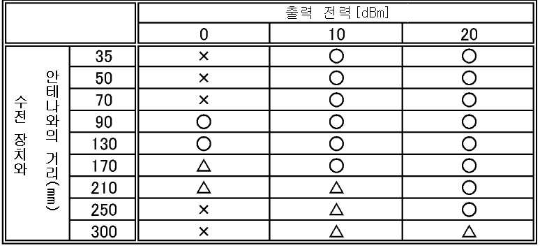
또한, 표 1에 있어서 통신 장치(630)로부터의 출력에 대해서, 수전 장치(600)가 정확한 데이터를 수신했을 경우에는 ○, 일부에서라도 상이한 데이터를 수신했을 경우에는 △, 데이터를 수신할 수 없었던 경우에는 X로 나타낸다.In addition, in Table 1, when the
표 1에서 나타낸 바와 같이, 0 dBm에 있어서는 90 ~ 130 mm의 범위에서 데이터를 정확하게 수신하고, 170 ~ 210 mm의 범위에서 일부 상이한 데이터를 수신한다. 또한, 10 dBm에 있어서는 35 ~ 170 mm의 범위에서 데이터를 정확하게 수신하고, 210 ~ 300 mm의 범위에서 일부 상이한 데이터를 수신한다. 또한, 20 dBm에서는 35 ~ 250 mm의 범위에서 데이터를 정확하게 수신하고, 300 mm의 범위에서 일부 상이한 데이터를 수신한다.As shown in Table 1, at 0 dBm, data is correctly received in the range of 90 to 130 mm, and some different data is received in the range of 170 to 210 mm. In addition, at 10 dBm, data is correctly received in the range of 35 to 170 mm, and some different data is received in the range of 210 to 300 mm. In addition, at 20 dBm, it correctly receives data in the range of 35 to 250 mm, and receives some different data in the range of 300 mm.
상기와 같이, 본 실시예에서 나타낸 수전 장치는 무선 통신이 가능한 것이 확인되었다.As described above, it was confirmed that the power receiving device shown in this embodiment is capable of wireless communication.
본 실시예는 다른 실시예 또는 다른 실시형태에서 기재한 구성과 적절히 조합하여 실시할 수 있다.
This example can be implemented in appropriate combination with any of the structures described in the other examples or other embodiments.
102 : 기판 104 : 수전용 공명 코일
106 : 용량 소자 108 : 수전용 코일
200 : 수전 장치 202 : 방향성 결합기
204 : 부하 변조 소자 206 : 변조 트랜지스터
208 : 정류 회로 210 : DCDC 컨버터
212 : 부하 214 : 수신 회로
220 : 수신용 컨트롤러 230 : 비접촉 급전부
240 : 무선 통신부 250 : 송전 장치
252 : 용량 소자 254 : 송전용 공명 코일
256 : 송전용 코일 258 : 고주파 전원
270 : 통신 장치 272 : 안테나
274 : 방향성 결합기 276 : 변조 회로
278 : 발진기 280 : 수전 회로
282 : 통신용 컨트롤러 284 : 정합 회로
500 : 수전 장치 502 : 기판
504 : 수전용 공명 코일 506 : 용량 소자
508 : 수전용 코일 510 : 배선
512 : 소켓 514 : 전구
520 : 송전대 522 : 송전용 공명 코일
550 : 송전 장치 600 : 수전 장치
602 : 기판 604 : 수전용 공명 코일
606 : 용량 소자 608 : 수전용 코일
610 : 배선 612 : 칩
620 : 신호 해석 장치 630 : 통신 장치
632 : 안테나 634 : 통신용 콘트롤러
636 : 부하 700 : 송전 장치
702 : 전원 플러그 704 : 휴대 전화
706 : 수전 장치 708 : 휴대 전화
710 : 수전 장치 711 : 케이스
712 : 스피커부 713 : 표시부
714 : 마이크부 716 : 단자부
718 :케이스 722 : 단자부
723 : 카메라 모듈 724 : 렌즈부
726 : 라이트 728 : 배터리102
106: capacitive element 108: power receiving coil
200: power receiving device 202: directional coupler
204: load modulation element 206: modulation transistor
208: rectifier circuit 210: DCDC converter
212: load 214: receiving circuit
220: reception controller 230: non-contact feeder
240: wireless communication unit 250: power transmission device
252
256: coil for power transmission 258: high frequency power supply
270: communication device 272: antenna
274
278: oscillator 280: power receiver circuit
282: communication controller 284: matching circuit
500: power receiving device 502: substrate
504: Resonant resonance coil 506: Capacitive element
508: power receiving coil 510: wiring
512: socket 514: light bulb
520: power transmission station 522: resonance coil for power transmission
550: power transmission device 600: power receiving device
602
606
610: wiring 612: chip
620: signal analysis device 630: communication device
632: antenna 634: communication controller
636: load 700: power transmission device
702: Power Plug 704: Mobile Phone
706: power receiver 708: mobile phone
710: power receiver 711: case
712: speaker portion 713: display portion
714: microphone 716: terminal
718: Case 722: Terminal
723: camera module 724: lens unit
726: Light 728: Battery
Claims (20)
상기 기판 위의 수전용 코일과,
상기 수전용 코일에 전기적으로 접속된 비접촉 급전부와,
상기 수전용 코일에 전기적으로 접속된 무선 통신부를 포함하고,
상기 비접촉 급전부와 상기 무선 통신부는 상기 기판 위에 제공된, 장치.
A resonance coil on the substrate,
A power receiving coil on the substrate;
A non-contact power supply unit electrically connected to the coil for power receiving,
A wireless communication unit electrically connected to the power receiving coil,
And the non-contact feed portion and the wireless communication portion are provided on the substrate.
상기 수전용 공명 코일은 상기 기판의 제 1 표면 위에 제공되어 있고 상기 수전용 코일은 상기 기판의 제 2 표면 위에 제공되어 있는, 장치.
The method of claim 1,
And the power receiving resonance coil is provided over the first surface of the substrate and the power receiving coil is provided over the second surface of the substrate.
상기 수전용 공명 코일과 상기 수전용 코일 중의 적어도 하나는 반송파와 전자기 유도를 사용하는 진폭 변조파 중의 하나의 신호를 수신하는, 장치.
The method of claim 1,
And at least one of the power receiving resonance coil and the power receiving coil receives a signal of one of a carrier wave and an amplitude modulated wave using electromagnetic induction.
상기 비접촉 급전부는 상기 수전용 코일에서 생성된 고주파 전압을 정류하는 정류 회로를 포함하고,
상기 정류 회로에 전기적으로 접속된 변환기와,
상기 변환기에 의해 변환된 전력이 부여되는 부하를 포함하는, 장치.
The method of claim 1,
The non-contact power supply unit includes a rectifier circuit for rectifying the high frequency voltage generated in the power receiving coil,
A converter electrically connected to the rectifier circuit;
And a load imparted with the power converted by the converter.
상기 무선 통신부는:
상기 신호를 수신하는 수신 회로와,
상기 수신 회로에 의해 수신된 상기 신호를 제어하는 수전용 컨트롤러와,
상기 수전용 컨트롤러에 전기적으로 접속된 변조 트랜지스터와,
상기 변조 트랜지스터에 전기적으로 접속된 부하 변조 소자를 포함하는, 장치.
The method of claim 1,
The wireless communication unit:
A receiving circuit for receiving the signal;
A power receiving controller controlling the signal received by the receiving circuit;
A modulation transistor electrically connected to the power receiving controller,
And a load modulation element electrically connected to the modulation transistor.
고주파 전원과,
송전 코일과,
송전 공명 코일을 포함하는 송전 장치를 포함하는, 시스템.
The apparatus according to claim 1;
A high-
Power transmission coil,
A power transmission device comprising a power transmission resonance coil.
발진기와,
변조 회로와,
매칭 회로와
상기 매칭 회로에 전기적으로 접속된 안테나를 포함하는 통신 장치를 구비한, 시스템.
The apparatus according to claim 1;
Oscillator,
With a modulation circuit,
With matching circuits
And a communication device comprising an antenna electrically connected to the matching circuit.
상기 수전용 공명 코일에 전기적으로 접속된 용량 소자와
상기 기판 위의 수전용 코일과,
상기 수전용 코일에 전기적으로 접속된 비접촉 급전부와,
상기 수전용 코일에 전기적으로 접속된 무선 통신부를 포함하고,
상기 비접촉 급전부와 상기 무선 통신부는 상기 기판 위에 제공된, 장치.
A resonance coil on the substrate,
A capacitive element electrically connected to the power receiving resonance coil;
A power receiving coil on the substrate;
A non-contact power supply unit electrically connected to the coil for power receiving,
A wireless communication unit electrically connected to the power receiving coil,
And the non-contact feed portion and the wireless communication portion are provided on the substrate.
상기 수전용 공명 코일과 상기 용량 소자는 상기 기판의 제 1 표면 위에 제공되어 있고 상기 수전용 코일은 상기 기판의 제 2 표면 위에 제공되어 있는, 장치.
The method of claim 8,
Wherein the power receiving resonance coil and the capacitive element are provided over a first surface of the substrate and the power receiving coil is provided over a second surface of the substrate.
상기 수전용 공명 코일과 상기 수전용 코일 중의 적어도 하나는 반송파와 전자기 유도를 사용하는 진폭 변조파 중의 하나의 신호를 수신하는, 장치.
The method of claim 8,
And at least one of the power receiving resonance coil and the power receiving coil receives a signal of one of a carrier wave and an amplitude modulated wave using electromagnetic induction.
상기 비접촉 급전부는:
상기 수전용 코일에서 생성된 고주파 전압을 정류하는 정류 회로와,
상기 정류 회로에 전기적으로 접속된 변환기와,
상기 변환기에 의해 변환된 전력이 부여되는 부하를 포함하는, 장치.
The method of claim 8,
The non-contact feed portion:
A rectifier circuit for rectifying the high frequency voltage generated by the power receiving coil;
A converter electrically connected to the rectifier circuit;
And a load imparted with the power converted by the converter.
상기 무선 통신부는:
상기 신호를 수신하는 수신 회로와,
상기 수신 회로에 의해 수신된 상기 신호를 제어하는 수전용 컨트롤러와,
상기 수전용 컨트롤러에 전기적으로 접속된 변조 트랜지스터와,
상기 변조 트랜지스터에 전기적으로 접속된 부하 변조 소자를 포함하는, 장치.
The method of claim 8,
The wireless communication unit:
A receiving circuit for receiving the signal;
A power receiving controller controlling the signal received by the receiving circuit;
A modulation transistor electrically connected to the power receiving controller,
And a load modulation element electrically connected to the modulation transistor.
고주파 전원과,
송전 코일과,
송전 공명 코일을 포함하는 송전 장치를 구비한, 시스템.
The apparatus according to claim 8;
A high-
Power transmission coil,
A system with a power transmission device comprising a power transmission resonance coil.
발진기와,
변조 회로와,
매칭 회로와
상기 매칭 회로에 전기적으로 접속된 안테나를 포함하는 통신 장치를 구비한, 시스템.
The apparatus according to claim 8;
Oscillator,
With a modulation circuit,
With matching circuits
And a communication device comprising an antenna electrically connected to the matching circuit.
상기 수전용 공명 코일과 수전 코일 사이에서 전자 유도에 의해 제 2 고주파 전압이 생성되는 수전용 코일을 가지고,
상기 수전용 공명 코일 또는 상기 수전용 코일 중 적어도 어느 한쪽이 전자 유도에 의해 반송파 또는 진폭 변조파에 의한 신호가 수신되고,
상기 수전용 코일은 비접촉 급전부 및 무선 통신부와 전기적으로 접속되고,
상기 비접촉 급전부는,
상기 수전용 코일에서 생성된 제 2 고주파 전압이 정류되는 정류 회로와,
상기 정류 회로와 전기적으로 접속된 변환기와,
상기 변환기에 의하여 변환된 전력이 부여되는 부하를 가지고,
상기 무선 통신부는,
상기 신호를 수신하는 수신 회로와,
상기 수신 회로가 수신한 상기 신호를 제어하는 수전용 컨트롤러와,
상기 수전용 컨트롤러와 전기적으로 접속된 변조 트랜지스터와,
상기 변조 트랜지스터와 전기적으로 접속된 부하 변조 소자를 가지고,
상기 비접촉 급전부와 상기 무선 통신부가 일체로 형성된, 수전 장치.
A resonance resonance coil for generating a first high frequency voltage by a resonance method;
And a power receiving coil in which a second high frequency voltage is generated by electromagnetic induction between the power receiving resonance coil and the power receiving coil.
At least one of the power receiving resonance coil and the power receiving coil receives a signal by a carrier wave or an amplitude modulated wave by electromagnetic induction,
The power receiving coil is electrically connected to the non-contact power supply unit and the wireless communication unit,
The non-contact feed section,
A rectifying circuit for rectifying a second high frequency voltage generated by the power receiving coil;
A converter electrically connected to the rectifier circuit;
Having a load to which power converted by the converter is imparted,
The wireless communication unit includes:
A receiving circuit for receiving the signal;
A power receiving controller controlling the signal received by the receiving circuit;
A modulation transistor electrically connected to the power receiving controller,
Having a load modulation element electrically connected with the modulation transistor,
The power receiving device, wherein the non-contact power supply unit and the wireless communication unit are integrally formed.
제 3 고주파 전압을 생성하는 고주파 전원,
상기 제 3 고주파 전압이 인가되는 송전용 코일,
상기 송전용 공명 코일과 상기 송전용 코일 사이에서 전자 유도에 의해 제 4 고주파 전압이 생성되는 송전용 공명 코일로 이루어진 송전 장치를 가지고,
상기 제 1 고주파 전압은 상기 송전용 공명 코일과 상기 수전 장치의 자계 공명에 의해 생성되는, 비접촉 급전 시스템.
The power receiving device according to claim 15,
High frequency power source to generate the third high frequency voltage,
A coil for power transmission to which the third high frequency voltage is applied;
And a power transmission device comprising a resonance coil for power transmission, wherein a fourth high frequency voltage is generated by electromagnetic induction between the resonance power transmission coil and the power transmission coil,
And the first high frequency voltage is generated by the resonance coil of the power transmission unit and the magnetic resonance of the power receiving device.
반송파를 발진하는 발진기,
상기 반송파를 진폭 변조파로 변조하는 변조 회로,
상기 진폭 변조파를 정합하는 정합 회로, 및
상기 정합 회로와 전기적으로 접속되어 안테나로 이루어진 통신 장치를 가지고,
상기 안테나와 상기 수전 장치의 전자 유도에 의해 반송파 또는 진폭 변조파에 의한 신호가 송수신되는, 무선 통신 시스템.
The power receiving device according to claim 15,
Oscillator oscillating carrier,
A modulation circuit for modulating the carrier wave with an amplitude modulated wave,
A matching circuit for matching the amplitude modulated wave, and
Has a communication device electrically connected with the matching circuit and composed of an antenna,
A signal by a carrier wave or an amplitude modulated wave is transmitted and received by electromagnetic induction of the antenna and the power receiving device.
상기 수전용 공명 코일과 수전용 코일의 전자 유도에 의해 제 2 고주파 전압이 생성되는 수전용 코일을 가지고,
상기 수전용 공명 코일 또는 상기 수전용 코일 중 적어도 어느 한쪽이 전자 유도에 의해 반송파 또는 진폭 변조파에 의한 신호가 수신되고,
상기 수전용 코일은 비접촉 급전부 및 무선 통신부와 전기적으로 접속되고,
상기 비접촉 급전부는,
상기 수전용 코일에서 생성된 제 2 고주파 전압이 정류되는 정류 회로와,
상기 정류 회로와 전기적으로 접속된 변환기와,
상기 변환기에 의하여 변환된 전력이 주어지는 부하를 가지고,
상기 무선 통신부는,
상기 신호를 수신하는 수신 회로와,
상기 수신 회로가 수신한 상기 신호를 제어하는 수전용 컨트롤러와,
상기 수전용 컨트롤러와 전기적으로 접속된 변조 트랜지스터와,
상기 변조 트랜지스터와 전기적으로 접속된 부하 변조 소자를 가지고,
상기 수전용 공명 코일과 상기 수전용 코일은 적어도 일부가 겹쳐서 배치되고,
상기 비접촉 급전부와 상기 무선 통신부가 일체로 형성된, 수전 장치.
A resonance resonance coil for generating a first high frequency voltage by a resonance method;
And a power receiving coil in which a second high frequency voltage is generated by electromagnetic induction of the power receiving resonance coil and the power receiving coil.
At least one of the power receiving resonance coil and the power receiving coil receives a signal by a carrier wave or an amplitude modulated wave by electromagnetic induction,
The power receiving coil is electrically connected to the non-contact power supply unit and the wireless communication unit,
The non-contact feed section,
A rectifying circuit for rectifying a second high frequency voltage generated by the power receiving coil;
A converter electrically connected to the rectifier circuit;
With a load given the power converted by the converter,
The wireless communication unit includes:
A receiving circuit for receiving the signal;
A power receiving controller controlling the signal received by the receiving circuit;
A modulation transistor electrically connected to the power receiving controller,
Having a load modulation element electrically connected with the modulation transistor,
At least a portion of the power receiving resonance coil and the power receiving coil are disposed to overlap each other,
The power receiving device, wherein the non-contact power supply unit and the wireless communication unit are integrally formed.
제 3 고주파 전압을 생성하는 고주파 전원,
상기 제 3 고주파 전압이 인가되는 송전용 코일, 및
상기 송전용 코일과 송전용 공진 코일의 전자 유도에 의해 제 4 고주파 전압이 생성되는 송전용 공명 코일로 이루어진 송전 장치를 가지고,
상기 송전용 공명 코일과 상기 수전 장치의 자계 공명에 의해 상기 제 1 고주파 전압이 생성되는, 비접촉 급전 시스템.
The power receiving device according to claim 18,
High frequency power source to generate the third high frequency voltage,
A power transmission coil to which the third high frequency voltage is applied, and
It has a power transmission device consisting of a resonance coil for power transmission in which a fourth high frequency voltage is generated by electromagnetic induction of the power transmission coil and the resonance coil for power transmission,
And the first high frequency voltage is generated by the resonance coil of the power transmission resonance and the magnetic field resonance of the power receiving device.
반송파를 발진하는 발진기,
상기 반송파를 진폭 변조파로 변조하는 변조 회로,
상기 진폭 변조파를 정합하는 정합 회로, 및
상기 정합 회로와 전기적으로 접속되어 안테나로 이루어진 통신 장치를 가지고,
상기 안테나와 상기 수전 장치의 전자 유도에 의해 반송파 또는 진폭 변조파에 의한 신호가 송수신되는, 무선 통신 시스템.
The power receiving device according to claim 18,
Oscillator oscillating carrier,
A modulation circuit for modulating the carrier wave with an amplitude modulated wave,
A matching circuit for matching the amplitude modulated wave, and
Has a communication device electrically connected with the matching circuit and composed of an antenna,
A signal by a carrier wave or an amplitude modulated wave is transmitted and received by electromagnetic induction of the antenna and the power receiving device.
Applications Claiming Priority (2)
| Application Number | Priority Date | Filing Date | Title |
|---|---|---|---|
| JP2011053317 | 2011-03-10 | ||
| JPJP-P-2011-053317 | 2011-03-10 |
Publications (1)
| Publication Number | Publication Date |
|---|---|
| KR20120103501A true KR20120103501A (en) | 2012-09-19 |
Family
ID=46794874
Family Applications (1)
| Application Number | Title | Priority Date | Filing Date |
|---|---|---|---|
| KR20120024224A KR20120103501A (en) | 2011-03-10 | 2012-03-09 | Power-receiving device, wireless power-feeding system including power-receiving device, and wireless communication system including power-receiving device |
Country Status (3)
| Country | Link |
|---|---|
| US (2) | US9887583B2 (en) |
| JP (1) | JP2012200136A (en) |
| KR (1) | KR20120103501A (en) |
Families Citing this family (200)
| Publication number | Priority date | Publication date | Assignee | Title |
|---|---|---|---|---|
| US9887583B2 (en) * | 2011-03-10 | 2018-02-06 | Semiconductor Energy Laboratory Co., Ltd. | Power-receiving device, wireless power-feeding system including power-receiving device, and wireless communication system including power-receiving device |
| US9099885B2 (en) | 2011-06-17 | 2015-08-04 | Semiconductor Energy Laboratory Co., Ltd. | Wireless power feeding system |
| US9502920B2 (en) | 2011-11-16 | 2016-11-22 | Semiconductor Energy Laboratory Co., Ltd. | Power receiving device, power transmission device, and power feeding system |
| US10141791B2 (en) | 2014-05-07 | 2018-11-27 | Energous Corporation | Systems and methods for controlling communications during wireless transmission of power using application programming interfaces |
| US9966765B1 (en) | 2013-06-25 | 2018-05-08 | Energous Corporation | Multi-mode transmitter |
| US10965164B2 (en) | 2012-07-06 | 2021-03-30 | Energous Corporation | Systems and methods of wirelessly delivering power to a receiver device |
| US9853692B1 (en) | 2014-05-23 | 2017-12-26 | Energous Corporation | Systems and methods for wireless power transmission |
| US9787103B1 (en) | 2013-08-06 | 2017-10-10 | Energous Corporation | Systems and methods for wirelessly delivering power to electronic devices that are unable to communicate with a transmitter |
| US9824815B2 (en) | 2013-05-10 | 2017-11-21 | Energous Corporation | Wireless charging and powering of healthcare gadgets and sensors |
| US9124125B2 (en) | 2013-05-10 | 2015-09-01 | Energous Corporation | Wireless power transmission with selective range |
| US9893554B2 (en) | 2014-07-14 | 2018-02-13 | Energous Corporation | System and method for providing health safety in a wireless power transmission system |
| US10211674B1 (en) | 2013-06-12 | 2019-02-19 | Energous Corporation | Wireless charging using selected reflectors |
| US9859756B2 (en) | 2012-07-06 | 2018-01-02 | Energous Corporation | Transmittersand methods for adjusting wireless power transmission based on information from receivers |
| US9891669B2 (en) | 2014-08-21 | 2018-02-13 | Energous Corporation | Systems and methods for a configuration web service to provide configuration of a wireless power transmitter within a wireless power transmission system |
| US10063105B2 (en) | 2013-07-11 | 2018-08-28 | Energous Corporation | Proximity transmitters for wireless power charging systems |
| US9893768B2 (en) | 2012-07-06 | 2018-02-13 | Energous Corporation | Methodology for multiple pocket-forming |
| US10224982B1 (en) | 2013-07-11 | 2019-03-05 | Energous Corporation | Wireless power transmitters for transmitting wireless power and tracking whether wireless power receivers are within authorized locations |
| US10206185B2 (en) | 2013-05-10 | 2019-02-12 | Energous Corporation | System and methods for wireless power transmission to an electronic device in accordance with user-defined restrictions |
| US9948135B2 (en) | 2015-09-22 | 2018-04-17 | Energous Corporation | Systems and methods for identifying sensitive objects in a wireless charging transmission field |
| US9831718B2 (en) | 2013-07-25 | 2017-11-28 | Energous Corporation | TV with integrated wireless power transmitter |
| US9876394B1 (en) | 2014-05-07 | 2018-01-23 | Energous Corporation | Boost-charger-boost system for enhanced power delivery |
| US9843201B1 (en) | 2012-07-06 | 2017-12-12 | Energous Corporation | Wireless power transmitter that selects antenna sets for transmitting wireless power to a receiver based on location of the receiver, and methods of use thereof |
| US9939864B1 (en) | 2014-08-21 | 2018-04-10 | Energous Corporation | System and method to control a wireless power transmission system by configuration of wireless power transmission control parameters |
| US10141768B2 (en) | 2013-06-03 | 2018-11-27 | Energous Corporation | Systems and methods for maximizing wireless power transfer efficiency by instructing a user to change a receiver device's position |
| US9941747B2 (en) | 2014-07-14 | 2018-04-10 | Energous Corporation | System and method for manually selecting and deselecting devices to charge in a wireless power network |
| US10223717B1 (en) | 2014-05-23 | 2019-03-05 | Energous Corporation | Systems and methods for payment-based authorization of wireless power transmission service |
| US9876379B1 (en) | 2013-07-11 | 2018-01-23 | Energous Corporation | Wireless charging and powering of electronic devices in a vehicle |
| US10230266B1 (en) | 2014-02-06 | 2019-03-12 | Energous Corporation | Wireless power receivers that communicate status data indicating wireless power transmission effectiveness with a transmitter using a built-in communications component of a mobile device, and methods of use thereof |
| US10291055B1 (en) | 2014-12-29 | 2019-05-14 | Energous Corporation | Systems and methods for controlling far-field wireless power transmission based on battery power levels of a receiving device |
| US10256657B2 (en) | 2015-12-24 | 2019-04-09 | Energous Corporation | Antenna having coaxial structure for near field wireless power charging |
| US9906065B2 (en) | 2012-07-06 | 2018-02-27 | Energous Corporation | Systems and methods of transmitting power transmission waves based on signals received at first and second subsets of a transmitter's antenna array |
| US10205239B1 (en) | 2014-05-07 | 2019-02-12 | Energous Corporation | Compact PIFA antenna |
| US10218227B2 (en) | 2014-05-07 | 2019-02-26 | Energous Corporation | Compact PIFA antenna |
| US9252628B2 (en) | 2013-05-10 | 2016-02-02 | Energous Corporation | Laptop computer as a transmitter for wireless charging |
| US9806564B2 (en) | 2014-05-07 | 2017-10-31 | Energous Corporation | Integrated rectifier and boost converter for wireless power transmission |
| US10193396B1 (en) | 2014-05-07 | 2019-01-29 | Energous Corporation | Cluster management of transmitters in a wireless power transmission system |
| US9941707B1 (en) | 2013-07-19 | 2018-04-10 | Energous Corporation | Home base station for multiple room coverage with multiple transmitters |
| US9923386B1 (en) | 2012-07-06 | 2018-03-20 | Energous Corporation | Systems and methods for wireless power transmission by modifying a number of antenna elements used to transmit power waves to a receiver |
| US10124754B1 (en) | 2013-07-19 | 2018-11-13 | Energous Corporation | Wireless charging and powering of electronic sensors in a vehicle |
| US10186913B2 (en) | 2012-07-06 | 2019-01-22 | Energous Corporation | System and methods for pocket-forming based on constructive and destructive interferences to power one or more wireless power receivers using a wireless power transmitter including a plurality of antennas |
| US9793758B2 (en) | 2014-05-23 | 2017-10-17 | Energous Corporation | Enhanced transmitter using frequency control for wireless power transmission |
| US10224758B2 (en) | 2013-05-10 | 2019-03-05 | Energous Corporation | Wireless powering of electronic devices with selective delivery range |
| US9838083B2 (en) | 2014-07-21 | 2017-12-05 | Energous Corporation | Systems and methods for communication with remote management systems |
| US10050462B1 (en) | 2013-08-06 | 2018-08-14 | Energous Corporation | Social power sharing for mobile devices based on pocket-forming |
| US9812890B1 (en) | 2013-07-11 | 2017-11-07 | Energous Corporation | Portable wireless charging pad |
| US9438045B1 (en) | 2013-05-10 | 2016-09-06 | Energous Corporation | Methods and systems for maximum power point transfer in receivers |
| US9876648B2 (en) | 2014-08-21 | 2018-01-23 | Energous Corporation | System and method to control a wireless power transmission system by configuration of wireless power transmission control parameters |
| US10992185B2 (en) | 2012-07-06 | 2021-04-27 | Energous Corporation | Systems and methods of using electromagnetic waves to wirelessly deliver power to game controllers |
| US9859797B1 (en) | 2014-05-07 | 2018-01-02 | Energous Corporation | Synchronous rectifier design for wireless power receiver |
| US9899873B2 (en) | 2014-05-23 | 2018-02-20 | Energous Corporation | System and method for generating a power receiver identifier in a wireless power network |
| US10090886B1 (en) | 2014-07-14 | 2018-10-02 | Energous Corporation | System and method for enabling automatic charging schedules in a wireless power network to one or more devices |
| US10291066B1 (en) | 2014-05-07 | 2019-05-14 | Energous Corporation | Power transmission control systems and methods |
| US9859757B1 (en) | 2013-07-25 | 2018-01-02 | Energous Corporation | Antenna tile arrangements in electronic device enclosures |
| US9847679B2 (en) | 2014-05-07 | 2017-12-19 | Energous Corporation | System and method for controlling communication between wireless power transmitter managers |
| US9882430B1 (en) | 2014-05-07 | 2018-01-30 | Energous Corporation | Cluster management of transmitters in a wireless power transmission system |
| US10075008B1 (en) | 2014-07-14 | 2018-09-11 | Energous Corporation | Systems and methods for manually adjusting when receiving electronic devices are scheduled to receive wirelessly delivered power from a wireless power transmitter in a wireless power network |
| US10128693B2 (en) | 2014-07-14 | 2018-11-13 | Energous Corporation | System and method for providing health safety in a wireless power transmission system |
| US20150222126A1 (en) * | 2013-05-10 | 2015-08-06 | Energous | External or internal receiver for smart mobile devices |
| US9871398B1 (en) | 2013-07-01 | 2018-01-16 | Energous Corporation | Hybrid charging method for wireless power transmission based on pocket-forming |
| US9887739B2 (en) | 2012-07-06 | 2018-02-06 | Energous Corporation | Systems and methods for wireless power transmission by comparing voltage levels associated with power waves transmitted by antennas of a plurality of antennas of a transmitter to determine appropriate phase adjustments for the power waves |
| US9853458B1 (en) | 2014-05-07 | 2017-12-26 | Energous Corporation | Systems and methods for device and power receiver pairing |
| US9912199B2 (en) | 2012-07-06 | 2018-03-06 | Energous Corporation | Receivers for wireless power transmission |
| US9867062B1 (en) | 2014-07-21 | 2018-01-09 | Energous Corporation | System and methods for using a remote server to authorize a receiving device that has requested wireless power and to determine whether another receiving device should request wireless power in a wireless power transmission system |
| US10263432B1 (en) | 2013-06-25 | 2019-04-16 | Energous Corporation | Multi-mode transmitter with an antenna array for delivering wireless power and providing Wi-Fi access |
| US10211680B2 (en) | 2013-07-19 | 2019-02-19 | Energous Corporation | Method for 3 dimensional pocket-forming |
| US10270261B2 (en) | 2015-09-16 | 2019-04-23 | Energous Corporation | Systems and methods of object detection in wireless power charging systems |
| US10090699B1 (en) | 2013-11-01 | 2018-10-02 | Energous Corporation | Wireless powered house |
| US10063106B2 (en) | 2014-05-23 | 2018-08-28 | Energous Corporation | System and method for a self-system analysis in a wireless power transmission network |
| US9941754B2 (en) | 2012-07-06 | 2018-04-10 | Energous Corporation | Wireless power transmission with selective range |
| US10128699B2 (en) | 2014-07-14 | 2018-11-13 | Energous Corporation | Systems and methods of providing wireless power using receiver device sensor inputs |
| US9887584B1 (en) | 2014-08-21 | 2018-02-06 | Energous Corporation | Systems and methods for a configuration web service to provide configuration of a wireless power transmitter within a wireless power transmission system |
| US10211682B2 (en) | 2014-05-07 | 2019-02-19 | Energous Corporation | Systems and methods for controlling operation of a transmitter of a wireless power network based on user instructions received from an authenticated computing device powered or charged by a receiver of the wireless power network |
| US11502551B2 (en) | 2012-07-06 | 2022-11-15 | Energous Corporation | Wirelessly charging multiple wireless-power receivers using different subsets of an antenna array to focus energy at different locations |
| US10063064B1 (en) | 2014-05-23 | 2018-08-28 | Energous Corporation | System and method for generating a power receiver identifier in a wireless power network |
| US10148097B1 (en) | 2013-11-08 | 2018-12-04 | Energous Corporation | Systems and methods for using a predetermined number of communication channels of a wireless power transmitter to communicate with different wireless power receivers |
| US9882427B2 (en) | 2013-05-10 | 2018-01-30 | Energous Corporation | Wireless power delivery using a base station to control operations of a plurality of wireless power transmitters |
| US9900057B2 (en) | 2012-07-06 | 2018-02-20 | Energous Corporation | Systems and methods for assigning groups of antenas of a wireless power transmitter to different wireless power receivers, and determining effective phases to use for wirelessly transmitting power using the assigned groups of antennas |
| US10038337B1 (en) | 2013-09-16 | 2018-07-31 | Energous Corporation | Wireless power supply for rescue devices |
| US10381880B2 (en) | 2014-07-21 | 2019-08-13 | Energous Corporation | Integrated antenna structure arrays for wireless power transmission |
| US9143000B2 (en) | 2012-07-06 | 2015-09-22 | Energous Corporation | Portable wireless charging pad |
| US20140008993A1 (en) | 2012-07-06 | 2014-01-09 | DvineWave Inc. | Methodology for pocket-forming |
| US10199835B2 (en) | 2015-12-29 | 2019-02-05 | Energous Corporation | Radar motion detection using stepped frequency in wireless power transmission system |
| US9368020B1 (en) | 2013-05-10 | 2016-06-14 | Energous Corporation | Off-premises alert system and method for wireless power receivers in a wireless power network |
| US9899861B1 (en) | 2013-10-10 | 2018-02-20 | Energous Corporation | Wireless charging methods and systems for game controllers, based on pocket-forming |
| US9847677B1 (en) | 2013-10-10 | 2017-12-19 | Energous Corporation | Wireless charging and powering of healthcare gadgets and sensors |
| US10199849B1 (en) | 2014-08-21 | 2019-02-05 | Energous Corporation | Method for automatically testing the operational status of a wireless power receiver in a wireless power transmission system |
| US9991741B1 (en) | 2014-07-14 | 2018-06-05 | Energous Corporation | System for tracking and reporting status and usage information in a wireless power management system |
| US9973021B2 (en) | 2012-07-06 | 2018-05-15 | Energous Corporation | Receivers for wireless power transmission |
| US9825674B1 (en) | 2014-05-23 | 2017-11-21 | Energous Corporation | Enhanced transmitter that selects configurations of antenna elements for performing wireless power transmission and receiving functions |
| US10243414B1 (en) | 2014-05-07 | 2019-03-26 | Energous Corporation | Wearable device with wireless power and payload receiver |
| US10992187B2 (en) | 2012-07-06 | 2021-04-27 | Energous Corporation | System and methods of using electromagnetic waves to wirelessly deliver power to electronic devices |
| US10439448B2 (en) | 2014-08-21 | 2019-10-08 | Energous Corporation | Systems and methods for automatically testing the communication between wireless power transmitter and wireless power receiver |
| US9893555B1 (en) | 2013-10-10 | 2018-02-13 | Energous Corporation | Wireless charging of tools using a toolbox transmitter |
| US10312715B2 (en) | 2015-09-16 | 2019-06-04 | Energous Corporation | Systems and methods for wireless power charging |
| US20150326070A1 (en) | 2014-05-07 | 2015-11-12 | Energous Corporation | Methods and Systems for Maximum Power Point Transfer in Receivers |
| US10008889B2 (en) | 2014-08-21 | 2018-06-26 | Energous Corporation | Method for automatically testing the operational status of a wireless power receiver in a wireless power transmission system |
| US9843213B2 (en) | 2013-08-06 | 2017-12-12 | Energous Corporation | Social power sharing for mobile devices based on pocket-forming |
| US10103582B2 (en) | 2012-07-06 | 2018-10-16 | Energous Corporation | Transmitters for wireless power transmission |
| US9954374B1 (en) | 2014-05-23 | 2018-04-24 | Energous Corporation | System and method for self-system analysis for detecting a fault in a wireless power transmission Network |
| KR101991341B1 (en) * | 2013-01-04 | 2019-06-20 | 삼성전자 주식회사 | Wireless power reception device and wireless power transmission system |
| JP6282398B2 (en) * | 2013-02-19 | 2018-02-21 | 矢崎総業株式会社 | Electromagnetic induction coil |
| US9866279B2 (en) | 2013-05-10 | 2018-01-09 | Energous Corporation | Systems and methods for selecting which power transmitter should deliver wireless power to a receiving device in a wireless power delivery network |
| US9538382B2 (en) | 2013-05-10 | 2017-01-03 | Energous Corporation | System and method for smart registration of wireless power receivers in a wireless power network |
| US9537357B2 (en) | 2013-05-10 | 2017-01-03 | Energous Corporation | Wireless sound charging methods and systems for game controllers, based on pocket-forming |
| US9419443B2 (en) | 2013-05-10 | 2016-08-16 | Energous Corporation | Transducer sound arrangement for pocket-forming |
| US9819230B2 (en) | 2014-05-07 | 2017-11-14 | Energous Corporation | Enhanced receiver for wireless power transmission |
| US9843763B2 (en) | 2013-05-10 | 2017-12-12 | Energous Corporation | TV system with wireless power transmitter |
| US10103552B1 (en) | 2013-06-03 | 2018-10-16 | Energous Corporation | Protocols for authenticated wireless power transmission |
| US10003211B1 (en) | 2013-06-17 | 2018-06-19 | Energous Corporation | Battery life of portable electronic devices |
| US10021523B2 (en) | 2013-07-11 | 2018-07-10 | Energous Corporation | Proximity transmitters for wireless power charging systems |
| US9979440B1 (en) | 2013-07-25 | 2018-05-22 | Energous Corporation | Antenna tile arrangements configured to operate as one functional unit |
| EP3104495B1 (en) * | 2014-01-20 | 2018-09-26 | Hitachi Automotive Systems, Ltd. | Rotating body noncontact power feeding device and torque sensor |
| US10075017B2 (en) * | 2014-02-06 | 2018-09-11 | Energous Corporation | External or internal wireless power receiver with spaced-apart antenna elements for charging or powering mobile devices using wirelessly delivered power |
| US9935482B1 (en) | 2014-02-06 | 2018-04-03 | Energous Corporation | Wireless power transmitters that transmit at determined times based on power availability and consumption at a receiving mobile device |
| DE102014002876A1 (en) * | 2014-03-05 | 2015-09-10 | Supa Wireless Gmbh | Arrangement for an inductive energy transfer |
| US10158257B2 (en) | 2014-05-01 | 2018-12-18 | Energous Corporation | System and methods for using sound waves to wirelessly deliver power to electronic devices |
| US9966784B2 (en) | 2014-06-03 | 2018-05-08 | Energous Corporation | Systems and methods for extending battery life of portable electronic devices charged by sound |
| US10170917B1 (en) | 2014-05-07 | 2019-01-01 | Energous Corporation | Systems and methods for managing and controlling a wireless power network by establishing time intervals during which receivers communicate with a transmitter |
| US10153645B1 (en) | 2014-05-07 | 2018-12-11 | Energous Corporation | Systems and methods for designating a master power transmitter in a cluster of wireless power transmitters |
| US10153653B1 (en) | 2014-05-07 | 2018-12-11 | Energous Corporation | Systems and methods for using application programming interfaces to control communications between a transmitter and a receiver |
| US9973008B1 (en) | 2014-05-07 | 2018-05-15 | Energous Corporation | Wireless power receiver with boost converters directly coupled to a storage element |
| US9800172B1 (en) | 2014-05-07 | 2017-10-24 | Energous Corporation | Integrated rectifier and boost converter for boosting voltage received from wireless power transmission waves |
| US9876536B1 (en) | 2014-05-23 | 2018-01-23 | Energous Corporation | Systems and methods for assigning groups of antennas to transmit wireless power to different wireless power receivers |
| US10068703B1 (en) | 2014-07-21 | 2018-09-04 | Energous Corporation | Integrated miniature PIFA with artificial magnetic conductor metamaterials |
| US10116143B1 (en) | 2014-07-21 | 2018-10-30 | Energous Corporation | Integrated antenna arrays for wireless power transmission |
| US9871301B2 (en) | 2014-07-21 | 2018-01-16 | Energous Corporation | Integrated miniature PIFA with artificial magnetic conductor metamaterials |
| WO2016019205A1 (en) | 2014-07-30 | 2016-02-04 | Alfred E Mann Foundation For Scientific Research | Wireless power transfer and communications |
| US10454307B2 (en) | 2014-08-04 | 2019-10-22 | Jabil Inc. | Wireless power apparatus, system and method |
| US9917477B1 (en) | 2014-08-21 | 2018-03-13 | Energous Corporation | Systems and methods for automatically testing the communication between power transmitter and wireless receiver |
| US9965009B1 (en) | 2014-08-21 | 2018-05-08 | Energous Corporation | Systems and methods for assigning a power receiver to individual power transmitters based on location of the power receiver |
| US10122415B2 (en) | 2014-12-27 | 2018-11-06 | Energous Corporation | Systems and methods for assigning a set of antennas of a wireless power transmitter to a wireless power receiver based on a location of the wireless power receiver |
| US9893535B2 (en) | 2015-02-13 | 2018-02-13 | Energous Corporation | Systems and methods for determining optimal charging positions to maximize efficiency of power received from wirelessly delivered sound wave energy |
| US10523033B2 (en) | 2015-09-15 | 2019-12-31 | Energous Corporation | Receiver devices configured to determine location within a transmission field |
| US9906275B2 (en) | 2015-09-15 | 2018-02-27 | Energous Corporation | Identifying receivers in a wireless charging transmission field |
| US10158259B1 (en) | 2015-09-16 | 2018-12-18 | Energous Corporation | Systems and methods for identifying receivers in a transmission field by transmitting exploratory power waves towards different segments of a transmission field |
| US9871387B1 (en) | 2015-09-16 | 2018-01-16 | Energous Corporation | Systems and methods of object detection using one or more video cameras in wireless power charging systems |
| US9893538B1 (en) | 2015-09-16 | 2018-02-13 | Energous Corporation | Systems and methods of object detection in wireless power charging systems |
| US10186893B2 (en) | 2015-09-16 | 2019-01-22 | Energous Corporation | Systems and methods for real time or near real time wireless communications between a wireless power transmitter and a wireless power receiver |
| US10199850B2 (en) | 2015-09-16 | 2019-02-05 | Energous Corporation | Systems and methods for wirelessly transmitting power from a transmitter to a receiver by determining refined locations of the receiver in a segmented transmission field associated with the transmitter |
| US10008875B1 (en) | 2015-09-16 | 2018-06-26 | Energous Corporation | Wireless power transmitter configured to transmit power waves to a predicted location of a moving wireless power receiver |
| US10778041B2 (en) | 2015-09-16 | 2020-09-15 | Energous Corporation | Systems and methods for generating power waves in a wireless power transmission system |
| US9941752B2 (en) | 2015-09-16 | 2018-04-10 | Energous Corporation | Systems and methods of object detection in wireless power charging systems |
| US10211685B2 (en) | 2015-09-16 | 2019-02-19 | Energous Corporation | Systems and methods for real or near real time wireless communications between a wireless power transmitter and a wireless power receiver |
| US11710321B2 (en) | 2015-09-16 | 2023-07-25 | Energous Corporation | Systems and methods of object detection in wireless power charging systems |
| US10135294B1 (en) | 2015-09-22 | 2018-11-20 | Energous Corporation | Systems and methods for preconfiguring transmission devices for power wave transmissions based on location data of one or more receivers |
| US10153660B1 (en) | 2015-09-22 | 2018-12-11 | Energous Corporation | Systems and methods for preconfiguring sensor data for wireless charging systems |
| US10135295B2 (en) | 2015-09-22 | 2018-11-20 | Energous Corporation | Systems and methods for nullifying energy levels for wireless power transmission waves |
| US10020678B1 (en) | 2015-09-22 | 2018-07-10 | Energous Corporation | Systems and methods for selecting antennas to generate and transmit power transmission waves |
| US10027168B2 (en) | 2015-09-22 | 2018-07-17 | Energous Corporation | Systems and methods for generating and transmitting wireless power transmission waves using antennas having a spacing that is selected by the transmitter |
| US10033222B1 (en) | 2015-09-22 | 2018-07-24 | Energous Corporation | Systems and methods for determining and generating a waveform for wireless power transmission waves |
| US10128686B1 (en) | 2015-09-22 | 2018-11-13 | Energous Corporation | Systems and methods for identifying receiver locations using sensor technologies |
| US10050470B1 (en) | 2015-09-22 | 2018-08-14 | Energous Corporation | Wireless power transmission device having antennas oriented in three dimensions |
| US10476302B2 (en) * | 2015-10-02 | 2019-11-12 | Avago Technologies International Sales Pte. Limited | Wireless power transfer load modulation enhancement |
| US10333332B1 (en) | 2015-10-13 | 2019-06-25 | Energous Corporation | Cross-polarized dipole antenna |
| US10734717B2 (en) | 2015-10-13 | 2020-08-04 | Energous Corporation | 3D ceramic mold antenna |
| US9899744B1 (en) | 2015-10-28 | 2018-02-20 | Energous Corporation | Antenna for wireless charging systems |
| US9853485B2 (en) | 2015-10-28 | 2017-12-26 | Energous Corporation | Antenna for wireless charging systems |
| US10135112B1 (en) | 2015-11-02 | 2018-11-20 | Energous Corporation | 3D antenna mount |
| US10027180B1 (en) | 2015-11-02 | 2018-07-17 | Energous Corporation | 3D triple linear antenna that acts as heat sink |
| US10063108B1 (en) | 2015-11-02 | 2018-08-28 | Energous Corporation | Stamped three-dimensional antenna |
| US10320446B2 (en) | 2015-12-24 | 2019-06-11 | Energous Corporation | Miniaturized highly-efficient designs for near-field power transfer system |
| US10027159B2 (en) | 2015-12-24 | 2018-07-17 | Energous Corporation | Antenna for transmitting wireless power signals |
| US10079515B2 (en) | 2016-12-12 | 2018-09-18 | Energous Corporation | Near-field RF charging pad with multi-band antenna element with adaptive loading to efficiently charge an electronic device at any position on the pad |
| US11863001B2 (en) | 2015-12-24 | 2024-01-02 | Energous Corporation | Near-field antenna for wireless power transmission with antenna elements that follow meandering patterns |
| US10135286B2 (en) | 2015-12-24 | 2018-11-20 | Energous Corporation | Near field transmitters for wireless power charging of an electronic device by leaking RF energy through an aperture offset from a patch antenna |
| US10038332B1 (en) | 2015-12-24 | 2018-07-31 | Energous Corporation | Systems and methods of wireless power charging through multiple receiving devices |
| US10256677B2 (en) | 2016-12-12 | 2019-04-09 | Energous Corporation | Near-field RF charging pad with adaptive loading to efficiently charge an electronic device at any position on the pad |
| US10008886B2 (en) | 2015-12-29 | 2018-06-26 | Energous Corporation | Modular antennas with heat sinks in wireless power transmission systems |
| US10923954B2 (en) | 2016-11-03 | 2021-02-16 | Energous Corporation | Wireless power receiver with a synchronous rectifier |
| KR102185600B1 (en) | 2016-12-12 | 2020-12-03 | 에너저스 코포레이션 | A method of selectively activating antenna zones of a near field charging pad to maximize transmitted wireless power |
| US10680319B2 (en) | 2017-01-06 | 2020-06-09 | Energous Corporation | Devices and methods for reducing mutual coupling effects in wireless power transmission systems |
| US10439442B2 (en) | 2017-01-24 | 2019-10-08 | Energous Corporation | Microstrip antennas for wireless power transmitters |
| US10389161B2 (en) | 2017-03-15 | 2019-08-20 | Energous Corporation | Surface mount dielectric antennas for wireless power transmitters |
| CN110199570B (en) * | 2017-01-27 | 2021-08-13 | 三菱电机株式会社 | Induction heating cooker |
| KR102589437B1 (en) * | 2017-02-14 | 2023-10-16 | 삼성전자 주식회사 | Electronic device having coil antenna |
| US11011942B2 (en) | 2017-03-30 | 2021-05-18 | Energous Corporation | Flat antennas having two or more resonant frequencies for use in wireless power transmission systems |
| US10854960B2 (en) * | 2017-05-02 | 2020-12-01 | Richard A. Bean | Electromagnetic energy harvesting devices and methods |
| US10511097B2 (en) | 2017-05-12 | 2019-12-17 | Energous Corporation | Near-field antennas for accumulating energy at a near-field distance with minimal far-field gain |
| JP7187135B2 (en) * | 2017-05-16 | 2022-12-12 | ラピスセミコンダクタ株式会社 | Wireless power receiving device, wireless power supply device, wireless power transmission system, and excessive magnetic field protection method for wireless power receiving device |
| US11462949B2 (en) | 2017-05-16 | 2022-10-04 | Wireless electrical Grid LAN, WiGL Inc | Wireless charging method and system |
| US10848853B2 (en) | 2017-06-23 | 2020-11-24 | Energous Corporation | Systems, methods, and devices for utilizing a wire of a sound-producing device as an antenna for receipt of wirelessly delivered power |
| US10122219B1 (en) | 2017-10-10 | 2018-11-06 | Energous Corporation | Systems, methods, and devices for using a battery as a antenna for receiving wirelessly delivered power from radio frequency power waves |
| US11342798B2 (en) | 2017-10-30 | 2022-05-24 | Energous Corporation | Systems and methods for managing coexistence of wireless-power signals and data signals operating in a same frequency band |
| US10615647B2 (en) | 2018-02-02 | 2020-04-07 | Energous Corporation | Systems and methods for detecting wireless power receivers and other objects at a near-field charging pad |
| US11159057B2 (en) | 2018-03-14 | 2021-10-26 | Energous Corporation | Loop antennas with selectively-activated feeds to control propagation patterns of wireless power signals |
| US11515732B2 (en) | 2018-06-25 | 2022-11-29 | Energous Corporation | Power wave transmission techniques to focus wirelessly delivered power at a receiving device |
| US11437735B2 (en) | 2018-11-14 | 2022-09-06 | Energous Corporation | Systems for receiving electromagnetic energy using antennas that are minimally affected by the presence of the human body |
| WO2020160015A1 (en) | 2019-01-28 | 2020-08-06 | Energous Corporation | Systems and methods for miniaturized antenna for wireless power transmissions |
| KR20210123329A (en) | 2019-02-06 | 2021-10-13 | 에너저스 코포레이션 | System and method for estimating optimal phase for use with individual antennas in an antenna array |
| EP3952002A4 (en) * | 2019-03-28 | 2023-04-19 | Aoi Japan Co., Ltd. | Wireless power feeding system having battery mounted device engaged with power receiving device with light unit mounted |
| EP4032169A4 (en) | 2019-09-20 | 2023-12-06 | Energous Corporation | Classifying and detecting foreign objects using a power amplifier controller integrated circuit in wireless power transmission systems |
| CN115104234A (en) | 2019-09-20 | 2022-09-23 | 艾诺格思公司 | System and method for protecting a wireless power receiver using multiple rectifiers and establishing in-band communication using multiple rectifiers |
| US11381118B2 (en) | 2019-09-20 | 2022-07-05 | Energous Corporation | Systems and methods for machine learning based foreign object detection for wireless power transmission |
| WO2021055898A1 (en) | 2019-09-20 | 2021-03-25 | Energous Corporation | Systems and methods for machine learning based foreign object detection for wireless power transmission |
| US11355966B2 (en) | 2019-12-13 | 2022-06-07 | Energous Corporation | Charging pad with guiding contours to align an electronic device on the charging pad and efficiently transfer near-field radio-frequency energy to the electronic device |
| US10985617B1 (en) | 2019-12-31 | 2021-04-20 | Energous Corporation | System for wirelessly transmitting energy at a near-field distance without using beam-forming control |
| CN111245431A (en) * | 2020-03-24 | 2020-06-05 | 德威(苏州)新能源有限公司 | Module framework integrating wireless power supply and signal interaction and application |
| US11799324B2 (en) | 2020-04-13 | 2023-10-24 | Energous Corporation | Wireless-power transmitting device for creating a uniform near-field charging area |
| CN113900596A (en) * | 2021-11-15 | 2022-01-07 | 上海市信产通信服务有限公司 | Method for rapidly reading equipment information by using wireless technology |
| US11916398B2 (en) | 2021-12-29 | 2024-02-27 | Energous Corporation | Small form-factor devices with integrated and modular harvesting receivers, and shelving-mounted wireless-power transmitters for use therewith |
Family Cites Families (22)
| Publication number | Priority date | Publication date | Assignee | Title |
|---|---|---|---|---|
| US4583099A (en) * | 1983-12-27 | 1986-04-15 | Polyonics Corporation | Resonant tag circuits useful in electronic security systems |
| SG54559A1 (en) | 1996-09-13 | 1998-11-16 | Hitachi Ltd | Power transmission system ic card and information communication system using ic card |
| JP3392016B2 (en) | 1996-09-13 | 2003-03-31 | 株式会社日立製作所 | Power transmission system and power transmission and information communication system |
| TWI295530B (en) | 2002-06-28 | 2008-04-01 | Canon Kk | Wireless communication apparatus and method |
| GB2393860B (en) * | 2002-09-27 | 2006-02-15 | Zap Wireless Technologies Ltd | Improvements relating to retention of rechargeable devices |
| US20090072782A1 (en) * | 2002-12-10 | 2009-03-19 | Mitch Randall | Versatile apparatus and method for electronic devices |
| US20070021140A1 (en) * | 2005-07-22 | 2007-01-25 | Keyes Marion A Iv | Wireless power transmission systems and methods |
| JP2008210301A (en) | 2007-02-28 | 2008-09-11 | Sony Corp | Storage medium, communication system, and control device |
| US7986059B2 (en) * | 2008-01-04 | 2011-07-26 | Pure Energy Solutions, Inc. | Device cover with embedded power receiver |
| JP5238420B2 (en) * | 2008-09-11 | 2013-07-17 | 矢崎総業株式会社 | Wireless charging system for vehicles |
| JP5390818B2 (en) | 2008-09-19 | 2014-01-15 | 矢崎総業株式会社 | Communication coil structure of wireless power transmission device |
| US8482158B2 (en) * | 2008-09-27 | 2013-07-09 | Witricity Corporation | Wireless energy transfer using variable size resonators and system monitoring |
| JP5324901B2 (en) | 2008-12-09 | 2013-10-23 | 日立コンシューマエレクトロニクス株式会社 | Non-contact power transmission system |
| US8338991B2 (en) * | 2009-03-20 | 2012-12-25 | Qualcomm Incorporated | Adaptive impedance tuning in wireless power transmission |
| JP2010252468A (en) * | 2009-04-14 | 2010-11-04 | Sony Corp | Power transmission device and method, power receiving device and method, and power transmission system |
| JP5495620B2 (en) | 2009-05-22 | 2014-05-21 | キヤノン株式会社 | Power supply |
| JP2010284065A (en) | 2009-06-08 | 2010-12-16 | Nec Tokin Corp | Power/signal transmission module, noncontact charging module, and noncontact charging and signal transmission systems |
| JP2011142748A (en) | 2010-01-07 | 2011-07-21 | Sony Corp | Wireless power supply system |
| WO2011093150A1 (en) | 2010-01-29 | 2011-08-04 | Semiconductor Energy Laboratory Co., Ltd. | Semiconductor device |
| US9240633B2 (en) * | 2010-05-28 | 2016-01-19 | Qualcomm Incorporated | Tunable wireless power device |
| JP2012186949A (en) * | 2011-03-07 | 2012-09-27 | Hitachi Maxell Energy Ltd | Non-contact power transmission device utilizing magnetic field resonance |
| US9887583B2 (en) * | 2011-03-10 | 2018-02-06 | Semiconductor Energy Laboratory Co., Ltd. | Power-receiving device, wireless power-feeding system including power-receiving device, and wireless communication system including power-receiving device |
-
2012
- 2012-03-05 US US13/412,175 patent/US9887583B2/en not_active Expired - Fee Related
- 2012-03-07 JP JP2012049885A patent/JP2012200136A/en not_active Withdrawn
- 2012-03-09 KR KR20120024224A patent/KR20120103501A/en not_active Application Discontinuation
-
2018
- 2018-01-31 US US15/884,698 patent/US10461585B2/en not_active Expired - Fee Related
Also Published As
| Publication number | Publication date |
|---|---|
| US9887583B2 (en) | 2018-02-06 |
| US20180152054A1 (en) | 2018-05-31 |
| US20120228956A1 (en) | 2012-09-13 |
| US10461585B2 (en) | 2019-10-29 |
| JP2012200136A (en) | 2012-10-18 |
Similar Documents
| Publication | Publication Date | Title |
|---|---|---|
| KR20120103501A (en) | Power-receiving device, wireless power-feeding system including power-receiving device, and wireless communication system including power-receiving device | |
| US10367267B2 (en) | Flexible printed circuit board for dual mode antennas, dual mode antenna and user device | |
| US10389183B2 (en) | Multi-mode wireless power receiving device and method | |
| US9124121B2 (en) | Combined antenna and inductive power receiver | |
| JP5835360B2 (en) | ANTENNA DEVICE, CARD-TYPE COMMUNICATION DEVICE, AND COMMUNICATION TERMINAL DEVICE | |
| US20110018358A1 (en) | Contactless power supplying communication apparatus, contactless power receiving communication apparatus, power supplying communication controlling method and power receiving communication controlling method | |
| KR101485569B1 (en) | Near Field Communication antenna for mobile handset with metallic case | |
| CN106910986B (en) | Multi-resonance ultra-wideband NFC antenna system | |
| JP2010045467A (en) | Ic tag | |
| US11043751B2 (en) | NFC antenna device in a metallic environment | |
| JP2011066759A (en) | Antenna device and communication device | |
| KR20140021694A (en) | Dual-mode antenna | |
| KR20150045985A (en) | Flexible Circuit Board for Dual-Mode Antenna, Dual-Mode Antenna and User Device | |
| US20180076525A1 (en) | Antenna and electronic device | |
| CN104124990A (en) | Terminal equipment with near field communication and wireless charging functions | |
| KR20140021693A (en) | Dual-mode antenna | |
| KR101720743B1 (en) | Dual-Mode Antenna | |
| KR20160103968A (en) | Dual-Mode Antenna and User Device | |
| JP2012085234A (en) | Transmission system and transmission device | |
| US10318853B2 (en) | Antenna module and portable terminal having same | |
| CN212011275U (en) | Antenna apparatus for wireless power charging and near field communication | |
| JP2011066760A (en) | Antenna device and communication device |
Legal Events
| Date | Code | Title | Description |
|---|---|---|---|
| A201 | Request for examination | ||
| E902 | Notification of reason for refusal | ||
| E601 | Decision to refuse application |