KR20120095300A - Illumination device for a camera - Google Patents
Illumination device for a camera Download PDFInfo
- Publication number
- KR20120095300A KR20120095300A KR1020120010927A KR20120010927A KR20120095300A KR 20120095300 A KR20120095300 A KR 20120095300A KR 1020120010927 A KR1020120010927 A KR 1020120010927A KR 20120010927 A KR20120010927 A KR 20120010927A KR 20120095300 A KR20120095300 A KR 20120095300A
- Authority
- KR
- South Korea
- Prior art keywords
- camera
- illumination
- distance
- lighting device
- light source
- Prior art date
Links
Images


Classifications
-
- H—ELECTRICITY
- H04—ELECTRIC COMMUNICATION TECHNIQUE
- H04N—PICTORIAL COMMUNICATION, e.g. TELEVISION
- H04N23/00—Cameras or camera modules comprising electronic image sensors; Control thereof
- H04N23/70—Circuitry for compensating brightness variation in the scene
- H04N23/74—Circuitry for compensating brightness variation in the scene by influencing the scene brightness using illuminating means
-
- F—MECHANICAL ENGINEERING; LIGHTING; HEATING; WEAPONS; BLASTING
- F21—LIGHTING
- F21V—FUNCTIONAL FEATURES OR DETAILS OF LIGHTING DEVICES OR SYSTEMS THEREOF; STRUCTURAL COMBINATIONS OF LIGHTING DEVICES WITH OTHER ARTICLES, NOT OTHERWISE PROVIDED FOR
- F21V14/00—Controlling the distribution of the light emitted by adjustment of elements
- F21V14/06—Controlling the distribution of the light emitted by adjustment of elements by movement of refractors
Abstract
Description
본 발명은 카메라에 의해 모니터링되는 장면을 조명하기 위한 조명 장치에 관한 것이고, 그리고 카메라에 의해 모니터링되는 장면을 조명하는 방법에 관한 것이다.The present invention relates to an illumination device for illuminating a scene monitored by a camera and to a method of illuminating a scene monitored by a camera.
특정 장소를 모니터링하는데 사용되는 감시 카메라는, 때때로, 모니터링을 위해 해당 카메라가 사용되는 그 환경의 좋은 영상을 제공할 수 있도록 추가적인 조명을 필요로 할 수 있다. 예를 들어, 카메라에 대해 자연광이 불충분한 때인 야외 환경에서의 야간 시간 동안이 그러한 경우이다. 이 경우, 감시 카메라와 함께 어떤 타입의 조명이 사용될 수 있다. 일반적으로 선택할 수 있는 것은, 감시 카메라에 의해 모니터링되는 장면을 조명하기 위해 적외선 혹은 백색광을 방출하는 발광 다이오드(Light Emitting Diode, LED)들을 사용하는 것이다. LED들은 외부 장치에 장착될 수 있거나, 카메라 하우징(camera housing) 혹은 카메라의 기계적 구조 내에 통합될 수 있다.Surveillance cameras used to monitor a particular location may sometimes need additional illumination to provide a good image of the environment in which the camera is used for monitoring. This is the case, for example, during night time in an outdoor environment when there is insufficient natural light for the camera. In this case, any type of illumination can be used with the surveillance camera. A common choice is to use light emitting diodes (LEDs) that emit infrared or white light to illuminate the scene being monitored by the surveillance camera. The LEDs can be mounted in an external device or integrated into the camera housing or the mechanical structure of the camera.
이러한 추가적인 조명이 (예를 들어, LED 형태로) 카메라에 통합되는 경우, 사용자는 더 간단한 설치 과정을 제공받을 수 있다. 그 이유는 어떠한 조명 장비도 개별적으로 설치될 필요가 없기 때문이다. 이것은 또한 설치 비용도 감소시킬 수 있다. 이것은 또한, 조명이 카메라의 가시선(line of sight)으로 적절하게 인도되는 것을 더 용이하게 보장하게 된다. 그러나, 통합된 LED들을 사용할 때의 문제점은, 이들이 많은 열을 발생시키는 경향이 있다는 것인데, 이것은 또한 카메라 내의 이미지 센서의 성능에 부정적 영향을 미칠 수 있다. LED들은 또한 상당량의 전력을 소비하는 경향이 있고, 이는 카메라의 전력 소비를 증가시킨다.If this additional lighting is integrated into the camera (eg in the form of an LED), the user may be provided with a simpler installation process. This is because no lighting equipment needs to be installed separately. This can also reduce installation costs. This also makes it easier to ensure that the illumination is properly directed to the line of sight of the camera. However, a problem with using integrated LEDs is that they tend to generate a lot of heat, which can also negatively affect the performance of the image sensor in the camera. LEDs also tend to consume a significant amount of power, which increases the camera's power consumption.
또 다른 문제는 카메라에 통합된 LED 혹은 외장 LED에 의해 제공되는 조명은 종종, 설치가 이미 완료되 버린 경우, LED 장치를 물리적으로 교체하지 않고서는 재구성하거나 조정할 수 없다는 것이다. 대신에, 감시 카메라의 실제 설치 이전에, 설치시의 이미징 조건에 맞는 적절한 조명 범위가 선택될 수 있지만, 이것은 일부 경우에 있어 많은 노력을 요구하는 번거로운 작업이 될 수 있다. 이것은 종종, 그 동작 동안 광학부의 고정된 이미징 설정치를 갖는 고정 초점 카메라를 설치할 때 행해지는 것이다.Another problem is that the illumination provided by LEDs or external LEDs integrated into the camera often cannot be reconfigured or adjusted unless the LED device is physically replaced if the installation has already been completed. Instead, prior to the actual installation of the surveillance camera, an appropriate illumination range can be selected to suit the imaging conditions at the time of installation, but this can be a cumbersome task that in some cases requires a lot of effort. This is often done when installing a fixed focus camera with fixed imaging settings of the optics during its operation.
그러나, 가변초점 카메라에서, 사전에 조명을 위한 설정치를 선택하는 것과 같은 그러한 것은 실현가능 하지 않은바, 왜냐하면 이러한 카메라는 그 동작 동안 초점 및/또는 줌 위치를 동적으로 변경시키기 때문이다. 그 동작 동안 특정 카메라에 대해 해당하는 모든 가능한 거리를 커버하기 위해 큰 범위를 갖는 LED 장치가 종종 가변초점 카메라용으로 선택된다. 그러나, 이것은 결과적으로, 대부분의 동작 시간 동안 필요한 것보다 더 큰 전력 소비 및 더 많은 발열을 일으킨다.However, in a variable focus camera, such as selecting a setting for illumination in advance is not feasible because such a camera dynamically changes the focus and / or zoom position during its operation. LED devices with large ranges are often selected for variable focus cameras to cover all applicable distances for a particular camera during its operation. However, this results in greater power consumption and more heat generation than necessary for most of the operating time.
과다한 발열 및 전력 소비가 갖는 문제는, 만약 카메라가 필요로 하는 광에 맞도록 조명이 제어될 수 있다면, 감소될 수 있다.The problem with excessive heat generation and power consumption can be reduced if the lighting can be controlled to match the light the camera needs.
특허문헌 DE 3622025에서는, TV 카메라용 적외선 조명이 개시되는바, 여기에는 다수의 적외선 다이오드들이 포함되어 있다. 적외선 조명으로부터의 방사선의 강도는 조명을 구동시키는 일정한 전압을 변경시킴으로써 제어될 수 있다.In patent document DE 3622025, infrared illumination for a TV camera is disclosed, which includes a plurality of infrared diodes. The intensity of radiation from infrared illumination can be controlled by changing the constant voltage that drives the illumination.
그러나, 이러한 공지된 방법에서, 다이오드로부터의 광은 언제나 큰 영역에 제공되고, 카메라의 초점에 있는 물체 혹은 영역에 맞게 조정될 수 없다. 따라서, 카메라가 필요로 하는 조명 및 특정 사용의 경우에 효율적으로 적합하도록 LED의 광학 출력을 제어함으로써, 발열 및 전력 소비에 관한 문제가 감소되는 그러한 조명 방법에 관한 필요성이 존재한다.In this known method, however, the light from the diode is always provided in a large area and cannot be adjusted to the object or area in focus of the camera. Thus, there is a need for such an illumination method in which the problem of heat generation and power consumption is reduced by controlling the optical output of the LED to be efficiently adapted to the lighting required by the camera and the specific use case.
본 발명의 목적은 발열 및 전력 소비에 관한 앞서의 문제를 경감시키는 조명 방법을 제공하는 것이고, 그리고 카메라가 필요로 하는 조명 및 특정 사용의 경우에 적합하도록 조명 장치의 광학 출력이 효율적으로 제어될 수 있는 그러한 조명 방법을 제공하는 것이다.It is an object of the present invention to provide an illumination method that alleviates the above problems of heat generation and power consumption, and that the optical output of the illumination device can be efficiently controlled to be suitable for the lighting and specific use cases required by the camera. To provide such a lighting method.
이러한 목적 및 다른 목적은 아래의 특허청구범위의 청구항 제1항에서 정의되는 바와 같은 그러한 특징을 갖는 조명 장치로 달성될 수 있고, 바람직한 실시예들이 그 종속 청구항들에서 정의되어 있다. 본 발명의 실시예들에 따르면, 카메라에 의해 모니터링되는 장면을 조명하는 조명 장치가 제공되고, 이러한 조명 장치는 제 1 발광 소스와 제 2 발광 소스를 포함하며, 여기서 제 1 발광 소스는 제 1 발광 소스가 조명 장치로부터의 제1의 거리에서 소정 크기의 제 1 영역 내에 본질적으로 조명을 제공하도록 구성된 제 1 렌즈를 구비하고, 그리고 제 2 발광 소스는 제 2 발광 소스가 조명 장치로부터의 제2의 거리에서 소정 크기의 제 2 영역 내에 본질적으로 조명을 제공하도록 구성된 제 2 렌즈를 구비한다. 제 1 발광 소스와 제 2 발광 소스의 출력 강도는 개별적으로 제어가능하다.These and other objects can be achieved with a lighting device having such a feature as defined in
이것은 제공되는 조명을 조정하여 카메라로부터 다양한 거리에 위치한 물체에 대한 조명이 달성될 수 있게 한다. 동시에, 발열 및 소비 전력은 발광 소스들로부터 방출되는 광의 보다 효율적인 사용에 의해 감소된다.This adjusts the illumination provided so that illumination for objects located at various distances from the camera can be achieved. At the same time, heat generation and power consumption are reduced by more efficient use of light emitted from light emitting sources.
이러한 조명 장치는 물체에 본질적으로 균일한 조명을 제공하도록 구성될 수 있고, 이는 카메라의 이미지 품질을 개선시킬 수 있다.Such lighting devices can be configured to provide essentially uniform illumination to the object, which can improve the image quality of the camera.
제 1 렌즈는 프레임 형태(예를 들어, 링 형상 혹은 직사각형 형상)의 조명 패턴을 생성하도록 구성될 수 있다. 더욱이, 제 2 렌즈는 프레임 내의 영역을 채우는 조명 패턴을 생성하도록 구성될 수 있다. 이러한 방식으로 수 개의 거리에서 물체에 본질적으로 균일한 조명이 용이하게 달성되고, 이것은 또한, 일정 크기의 영역 내에 본질적으로 조명을 제공할 수 있으며, 이로 인해, 전력을 더 절약할 수 있고, 발열을 더 감소시킬 수 있으며 이미지 품질을 더 개선시킬 수 있다.The first lens may be configured to generate an illumination pattern in the form of a frame (eg, ring or rectangular). Moreover, the second lens can be configured to generate an illumination pattern that fills an area within the frame. In this way an essentially uniform illumination of the object at several distances is easily achieved, which can also provide illumination essentially within a certain sized area, thereby further saving power and reducing heat generation. It can further reduce and further improve image quality.
제 1 발광 소스와 제 2 발광 소스 각각은 IR 방사선을 방출하도록 구성될 수 있는 LED를 포함할 수 있다. 이것은 야간 이미징 환경에서 특히 유용하다.Each of the first and second light emitting sources may comprise an LED that may be configured to emit IR radiation. This is particularly useful in night imaging environments.
조명 장치는 카메라로부터 줌 범위 값(zoom range value)을 수신하도록 구성될 수 있고, 그리고 줌 범위 값에 대응하는 카메라로부터의 일정 거리에 위치한 물체에 본질적으로 균일한 조명이 제공되도록 상기 수신된 줌 범위 값을 사용하여 제 1 발광 소스와 제 2 발광 소스의 출력 강도를 제어하도록 구성될 수 있다. 이것은 카메라의 초점에 있는 물체에 대해 전력 효율적 방식으로 적절한 조명을 보장할 수 있도록 한다.The lighting device may be configured to receive a zoom range value from the camera, and the received zoom range to provide essentially uniform illumination to an object located at a distance from the camera corresponding to the zoom range value. The value may be configured to control the output intensity of the first and second light emitting sources. This makes it possible to ensure proper illumination of the object in focus of the camera in a power efficient manner.
대안적 방법으로서, 조명 장치는 사용자 입력 인터페이스에 연결될 수 있고, 그리고 사용자 입력 인터페이스로부터 제3의 거리를 수신하도록 구성될 수 있으며, 카메라로부터의 제3의 거리에 존재하는 물체에 본질적으로 균일한 조명이 제공되도록 제3의 거리를 사용하여 제 1 발광 소스와 제 2 발광 소스의 출력 강도를 제어하도록 구성될 수 있다. 이것은 사용자 친화적 방식으로 고정 초점 카메라에 대한 조명 설정을 가능하게 한다. 또한, 카메라를 적절하게 설정한 이후, 필요한 경우, 조명 설정의 변경이 용이하다.As an alternative method, the lighting device can be connected to the user input interface and can be configured to receive a third distance from the user input interface, wherein the illumination device is essentially uniformly illuminated to an object present at the third distance from the camera. This may be configured to control the output intensity of the first and second light emitting sources using a third distance. This enables lighting settings for fixed focus cameras in a user friendly manner. In addition, after setting the camera appropriately, it is easy to change the lighting setting if necessary.
앞서의 장점은 또한, 본 발명의 실시예에 따른 조명 장치를 포함하는 카메라 및 방법에 의해 달성된다.The above advantages are also achieved by a camera and method comprising a lighting device according to an embodiment of the invention.
본 발명의 실시예들에 따른 장면을 조명하는 방법은,Method for illuminating a scene according to embodiments of the present invention,
제 1 발광 소스를 제공하는 단계와, 여기서 제 1 발광 소스는 제 1 발광 소스가 조명 장치로부터의 제1의 거리에서 소정 크기의 제 1 영역 내에 본질적으로 조명을 제공하도록 구성된 제 1 렌즈를 구비하고,Providing a first light source and wherein the first light source has a first lens configured such that the first light source is essentially providing illumination within a first area of a predetermined size at a first distance from the illumination device; ,
제 2 발광 소스를 제공하는 단계와, 여기서 제 2 발광 소스는 제 2 발광 소스가 조명 장치로부터의 제2의 거리에서 소정 크기의 제 2 영역 내에 본질적으로 조명을 제공하도록 구성된 제 2 렌즈를 구비하며, 그리고Providing a second light source, wherein the second light source has a second lens configured to provide illumination essentially within a second area of a predetermined size at a second distance from the lighting device; , And
제 1 발광 소스와 제 2 발광 소스의 출력 강도를 개별적으로 제어하는 단계를 포함할 수 있다.Individually controlling output intensities of the first and second light emitting sources.
이러한 방법은 또한,This method also,
조명 장치로부터의 제4의 거리에서 실제 광도에 관한 정보와, 제4의 거리에서 원하는 광도에 관한 정보를 카메라로부터 수신하는 단계와, 그리고Receiving from the camera information about the actual brightness at a fourth distance from the lighting device and information about the desired brightness at the fourth distance; and
이렇게 수신된 정보에 근거하여, 발광 소스들의 출력 강도를 조정하는 단계를 포함할 수 있다.Based on the received information, it may include adjusting the output intensity of the light emitting sources.
이러한 방식으로, 조명 장치에 대한 피드백이 만들어지는바, 이것은 카메라의 필요에 따라 조명을 훨씬 더 정밀하게 조정할 수 있게 한다.In this way, feedback is made to the lighting device, which makes it possible to adjust the lighting even more precisely according to the needs of the camera.
본 발명은 이제, 첨부되는 도식적 도면을 참조하여 예시적으로 상세히 설명된다.
도 1은 장면을 모니터링하는 카메라를 나타낸다.
도 2는 예시적 조명 장치의 상세 도면을 나타낸다.
도 3은 물체를 조명할 때 도 2의 조명 장치가 어떻게 사용되는 가를 나타낸다.
도 4는 또 다른 예시적 조명 장치의 상세 도면을 나타낸다.
도 5는 서로 다른 거리에서 물체를 조명할 때 도 4의 조명 장치를 나타낸 것이다.
도 6은 장면을 조명하는 방법을 나타낸 흐름도이다.
도 7은 장면을 조명하는 또 다른 방법을 나타낸 흐름도이다.The invention is now described in detail by way of example with reference to the accompanying schematic drawings.
1 shows a camera monitoring a scene.
2 shows a detailed view of an exemplary lighting device.
3 shows how the lighting device of FIG. 2 is used when illuminating an object.
4 shows a detailed view of another exemplary lighting device.
5 illustrates the lighting device of FIG. 4 when illuminating an object at different distances.
6 is a flowchart illustrating a method of illuminating a scene.
7 is a flowchart illustrating another method of illuminating a scene.
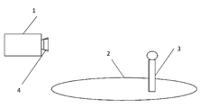
카메라(1)가 장면(2)을 모니터링하고, 이 장면(2)에서 물체(3)가 나타날 수 있다. 카메라(1)는 고정 초점 감시 카메라일 수 있거나, 혹은 가변초점 감시 카메라일 수 있는바, 가변초점 감시 카메라는 카메라로부터의 다양한 거리에서 물체에 대한 초점을 조정할 수 있다. 가변초점 카메라의 경우에, 줌 능력이 있을 수도 있고 없을 수도 있으며, 줌은 수동으로 제어될 수 있거나 또는 전기적으로 제어될 수 있다. 카메라는 또한 팬(pan)/틸트(tilt) 방식으로 움직일 수 있거나 혹은 고정될 수 있다. 카메라(1)는 조명 장치(4)에 연결되는바, 예를 들어, 조명 장치(4)는 카메라(1)에 통합될 수 있거나 카메라(1) 외부에 장착될 수 있다. 카메라(1) 및 조명 장치(4)는 유선으로 연결될 수 있거나, 무선으로 연결될 수 있으며, 또한, 이들은 직접 연결될 수 있거나, 네트워크를 통해 연결될 수 있다. 도 1에서, 조명 장치(4)는 카메라(1)의 하우징에 장착된 것으로 도시되어 있다.The
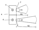
조명 장치(4)가 도 2에 도식적으로 제시되는바, 여기에는 두 개의 LED 장치들(5 및 6)이 포함되어 있고, 각각은 LED 장치로부터의 방출된 광이 각각의 렌즈(7 및 8)를 관통하도록 장착되어 있다. 조명 장치는 둘 이상의 LED 장치들을 포함할 수 있고, LED 장치들 각각은 카메라(1)가 필요로 하는 조명을 보다 더 정밀하게 조정할 수 있도록 각각의 렌즈를 구비하고 있다. 간결한 설명을 위해 도 2는 일정 비율로 도시되지 않았음에 유의해야 한다. 렌즈들(7, 8) 각각은 LED 장치들(5, 6)로부터 방출된 광에 대한 발산각(divergence angle)(A1 및 A2)을 정의한다. LED 장치들(5, 6)로부터 방출된 광의 강도는 LED 장치들(5, 6)에 공급된 전력을 제어함으로써 제어될 수 있다. 이것은 또한 LED 장치들(5, 6)에 대한 조명콘(illumination cone)의 근사화된 거리(B1 및 B2)를 제어하고, 본 경우에 이 거리는 각각의 LED 장치가 원하는 광도(예를 들어, 단위 면적당 mWFlux로 측정됨)를 제공하는 거리를 의미한다. 예를 들어, 10mWFlux/㎡이 원하는 광도일 수 있고, 그 다음에 조명콘의 길이는, LED 장치가 이러한 단위 면적당 광도를 제공하는 거리로서 정의된다.A
달리 말하면, 각각의 LED 장치(5, 6)의 발산각(A1, A2)은 각각의 렌즈(7,8)의 광학적 특성에 따라 달라지고, 그리고 조명콘의 길이(B1, B2)는 각각의 LED 장치(5, 6)의 출력 강도에 따라 달라진다. 이러한 예에서, LED 장치(5)의 발산각(A1)은 다른 LED 장치(6)의 발산각(A2)보다 더 크다. LED 장치(5)의 조명 범위는 조명콘의 길이(B1) 및 발산각(A1)에 의해 정의된다. 이에 대응하여, LED 장치(6)의 조명 범위는 조명콘의 길이(B2) 및 발산각(A2)에 의해 정의된다.In other words, the divergence angles A1 and A2 of the
예를 들어, 줌 능력을 갖는 카메라(1)에서, 렌즈들(7 및 8)이 적절하게 설계 혹은 선택될 수 있는바, 카메라(1)의 줌 렌즈가 완전히 줌 아웃(zoom out)될 때, 제 1 LED(5) 및 제 1 렌즈(7)가 카메라(1)의 시계에 딱 맞는 전체 사람 모습을 균일하게 조명하도록 렌즈(7)가 설계 혹은 선택될 수 있으며, 이때 그 사람까지의 거리는 B1과 동일하다. 제 2 렌즈(8) 및 제 2 LED(6)는, 카메라(1)의 줌 렌즈가 완전히 줌 인(zoom in)될 때, 카메라(1)의 시계에 딱 맞는 전체 사람 모습을 균일하게 조명하도록 설계된다. 이때 이 사람까지의 거리는 B2와 동일하다.For example, in a
서로 다른 타입의 LED들 혹은 다른 발광 소스들이 조명 장치(4)에 사용될 수 있다. 예를 들어, 야간 시간 동안 사용되고 적외선 사진용으로 구성되는 카메라(1)와 함께 사용하기 위해서 일반적으로 선택할 수 있는 것은, 적외선, 혹은 더 구체적으로는 근적외선(~850 nm) 스펙트럼에서 광을 방출하는 LED이지만, 백색광 LED가 또한 사용될 수 있다.Different types of LEDs or other light emitting sources can be used in the
조명 장치(4)의 예시적 실시예를 더 상세히 알아보면, 도 3은 도 2의 조명 장치(4)가 카메라(1)로부터 서로 다른 거리(D1, D2 및 D3)에 위치하고 있는 물체(3)를 조명하기 위해서 어떻게 사용될 수 있는가를 도식적으로 나타낸다. 본 발명자가 알아낸 바로는, 조명은 카메라(1)의 초점에 있는 물체 혹은 영역을 위해 주로 필요하고, 카메라(1)에 의해 모니터링되는 장면(2)의 배경을 위해서는 반드시 필요하지 않다는 것이다. 줌 능력을 갖는 카메라(1)를 사용하는 경우, 물체(3)는 근사적으로 동일한 크기를 갖는데, 이것이 의미하는 바는 조명될 필요가 있는 영역이 또한, 카메라로부터 관측되는 경우, 카메라(1)와 각각의 물체(3) 간의 거리와는 상관없이, 근사적으로 동일한 크기를 갖는다는 것이다. 달리 말하면, 조명될 필요가 있는 영역의 크기는 특정 물체(3)에 대해 일정하다. 그 이유는 줌 기능을 갖는 카메라는 물체(3)가 카메라(1)로부터 멀리 이동하여도 물체(3)를 따라갈 수 있기 때문이다. 따라서, 카메라(1)에 의해 관측되는 물체(3)의 크기는 근사적으로 일정하고, 따라서 이것이 그 필요한 조명 영역이 된다.In more detail an exemplary embodiment of the
도 3에 도시된 바와 같이 카메라(1)에 상대적으로 근접해 있는 거리(D1)에서의 물체(3)는, 거리(D1)에서의 물체(3)를 조명할 수 있는 범위를 커버하기에 충분한 입력 전력을 상대적으로 더 큰 발산각(A1)을 갖는 LED 장치(5)에 공급함으로써, 조명될 수 있고, 이 경우 LED 장치(6)에는 어떠한 입력 전력도 공급되지 않는다. 대신에, 만약 카메라(1)로부터 멀리 떨어져 있는 거리(D3)에서 물체(3)가 존재한다면, 이 물체(3)는, 거리(D3)에서의 물체(3) 조명을 위해 적합한 범위를 제공하기에 충분한 입력 전력을 상대적으로 더 작은 발산각(A2)을 갖는 LED 장치(6)에 공급함으로써, 조명될 수 있다. 이러한 경우 LED 장치(5)에는 어떠한 전력도 공급되지 않는다. 유의해야 할 것으로, 거리(D3)에서의 조명 영역의 크기와 거리(D1)에서의 조명 영역의 크기는 본질적으로 동일한데, 이것이 의미하는 것은 이러한 거리에서 물체(3)는 본질적으로 동일한 방식으로 조명됨을 의미하며, 이는 동일한 크기 및 강도의 광이 물체(3) 상에 떨어짐을 나타낸다. 도 3에서, 가정할 수 있는 것으로서, 물체(3)는 일반적으로 카메라(1)로부터 그 범위가 D1과 D3 사이인 거리에서 나타날 수 있다.As shown in FIG. 3, the
일부 경우에 있어, 카메라(1)의 이미징 조건에 맞는 전체 조명 범위가 생성될 수 있도록 수 개의 LED 장치들로부터의 조명 범위가 결합될 수 있다.In some cases, the illumination ranges from several LED devices can be combined such that an entire illumination range can be created that matches the imaging conditions of the
거리(D1)와 거리(D3) 사이의 거리(D2)에 위치한 물체(3)에 대한 경우는 다음과 같다. 이 경우, 물체(3)를 조명하기 위해 양쪽 LED 장치들(5, 6)로부터의 광이 사용될 수 있는데, 예를 들어, 각각의 LED 장치의 최대 동작 입력 전력의 50%가 사용될 수 있다.The case of the
LED 장치들(5, 6)에 대한 입력 전력 제어는, 각각의 LED에 대해 "온(on)" 상태 및 "오프(off)" 상태를 가짐으로써, 혹은 수개의 수치형 단계(예를 들어, 각각의 LED 장치(5, 6)에 대해 최대 입력 전력의 0%, 25%, 50%, 75% 및 100%)로 입력 전력을 조정하거나 또는 연속적으로 입력 전력을 조정함으로써, 수행될 수 있다. 이것은 또한, 카메라(1)의 특정 이미징 설정치 또는 특정 사용의 경우를 위한 조명이, 서로 다른 LED 장치들(5, 6)의 입력 전력을 제어함으로써 맞춤 조정될 수 있음을 의미한다. 카메라(1)의 특정 이미징 조건에 대해 필요하지 않은 조명 범위를 제공하는 LED 장치 또는 장치들에는 전력이 공급되지 않는다. 이것은 모든 LED 장치들에 항상 전력이 공급되는 경우와 비교해 발열 및 전력 소비 양쪽 모두를 감소시킨다. 물체를 조명하기 위해 다수의 LED들을 결합하는 경우, 열 관련 성능 문제의 위험이 낮아지고, 에너지 효율이 개선될 수 있다. 후자의 경우는 일반적으로 LED가 전력을 더 필요로 하면 열이 더 발생하게 되기 때문인데, 이것이 의미하는 바는 하나의 LED를 100% 전력에서 사용하는 것보다 두 개의 LED를 결합하여 최대 전력의 50%에서 사용하는 것이 더 에너지 효율적임을 의미한다.Input power control for the
조명 장치에 다수의 LED들과 렌즈들을 결합시키는 것은 또한, 특정 상황에서의 필요에 따라 조명을 맞춤 조정할 수 있는 이점을 갖는다.Combining multiple LEDs and lenses in the lighting device also has the advantage of allowing the lighting to be tailored to the needs of a particular situation.
조명 장치(4)는 그 동작 동안 이미징 조건에 따라 조명을 동적으로 맞추는데 사용될 수 있고, 뿐만 아니라 카메라(1)가 구성 및 설치될 때 간단하고 효율적인 방식으로 적절한 조명을 선택하는데 사용될 수도 있다. 이것은 또한 LED 장치들을 교체할 그 어떤 필요성도 없이, 일단 자리를 잡은 카메라(1)의 조명 설정을 용이하게 변경시킬 수 있다. 예를 들어, 전기적으로 줌 가능한 카메라의 이미징 렌즈의 줌 값은, LED 장치들(5, 6)에 대한 입력 전력을 제어하기 위한 입력 파라미터로서 사용될 수 있다. 또 다른 예로서, 조명 범위(혹은 물체(3)까지의 (예측) 거리)는 사용자 인터페이스(예를 들어, 고정 초점 카메라의 사용자 인터페이스)에서 사용자에 의해 설정될 수 있다. 또 다른 선택사항으로는 고급 이미지 프로세싱을 사용하여 초점 평면까지의 거리를 계산하고, 이로부터 최적의 조명 설정을 얻어내고, 이에 따라 조명 장치(4)를 제어하는 것이다. 일 실시예의 경우, 제 1 단계에서, 줌 값은, 어떤 LED(들)를 활성화시킬지를 선택함과 아울러 이런 식으로 조명각을 정의하기 위해 사용된다. 제 2 단계에서, 초점 평면까지의 거리는, LED들에 대한 입력 전력을 제어함과 아울러 이런 식으로 조명 강도를 정의하기 위해 사용된다.The
또 다른 예에서, 일정 거리에서 카메라(1)에 의해 측정된 실제 광도는 그 거리에서의 원하는 광도와 비교될 수 있고, 그 결과는 LED들에 공급되는 전력을 조정하기 위해 사용될 수 있다.In another example, the actual luminous intensity measured by the
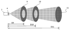
도 4 및 도 5에 제시된 바와 같이, 원형의 대칭적 조명콘과는 다른 조명 패턴을 생성시키기 위한 고급 렌즈 기술이 사용될 수 있다. 도 4에 도시되어 있는, 조명 장치(4)의 렌즈(7)는, LED 장치(5)가 카메라(1)에 의해 관측되는 장면의 주변 부분만을 조명하도록 본 예에서는 설계될 수 있는데, 즉 렌즈(7)는 프레임 형상의 조명 패턴(10)을 제공하도록 설계되고, 그리고 제 2 렌즈(8)는 LED 장치(6)로부터 방출되는 광이 본질적으로 원형 형상 또는 패턴(11)으로 프레임 형상(10) 내에 들도록 설계될 수 있다. 이러한 방식으로 LED 장치들의 효율적인 사용이 달성된다. 도 4에 도시된 바와 같이, 이것은 또한 조명 장치(4) 내에 제 3 LED 장치(12)를 부가시킴으로써 증진될 수 있는바, 제 3 LED 장치(12)는 렌즈(13)를 구비하고, 이 렌즈(13)는 LED(5)용 렌즈보다 훨씬 더 큰 발산각(A3)을 제공하며, 조명 패턴(10)을 또한 에워싸는 프레임 형상의 조명 패턴(9)을 생성한다. LED(12)의 조명 범위는 조명콘(B3)의 길이(즉, LED가 단위 면적당 일정 광도를 제공하게 되는 거리) 및 발산각(A3)에 의해 정의된다.As shown in Figures 4 and 5, advanced lens technology can be used to create an illumination pattern different from the circular symmetrical illumination cones. The
전체 구성은 또한 원형 형상과는 다른 형상을 생성하는 렌즈를 사용하여 구현될 수 있음에 유의해야 하는바, 예를 들어, 직사각형 형상 혹은 패턴이 일부 경우에 있어 유용할 수 있다. 또 달리 선택할 수 있는 것으로는, 브레셀 타입(Bresel type)의 프레임(즉, 안쪽 면이 프레임 중앙점에 관하여 볼록한 프레임 형상)을 사용하는 것이다. 카메라에 대한 적절한 조명 설정을 생성하기 위해 필요한 것이 무엇인가에 따라 다른 형상 혹은 패턴이 또한 사용될 수 있다.It should be noted that the overall configuration may also be implemented using lenses that produce shapes other than circular shapes, for example rectangular shapes or patterns may be useful in some cases. Another alternative is to use a Bressel type frame (i.e., a frame shape whose inner surface is convex with respect to the frame center point). Other shapes or patterns may also be used, depending on what is needed to create the appropriate lighting settings for the camera.
도 4 및 도 5의 예에서의 렌즈는 카메라(1)로부터의 소정 거리에서의 조명 영역의 크기가 본질적으로 동일하도록 설계되어 있음에 유의해야 한다. 도 5에서, 이것은 거리(D9, D10 및 D11)에서의 예로 나타나는바, 여기서 세 개의 LED들(5, 6 및 12)의 결합은 그 결합시 본질적으로 동일한 크기의 균일하게 조명된 영역을 제공한다. 도 5에서, LED 장치들(5, 6 및 12) 각각의 조명콘이 도시되는바, 이것은 조명콘의 직경이 세 개의 LED들(5, 6 및 12) 모두에 대해 동일하게 되는 그러한 양의 전력이 LED 장치들(5, 6 및 12)에 공급되는 경우인바, 즉, 달리 말하면, 각각의 LED(5, 6 또는 12)로부터의 단위 면적당 일정 강도의 광이 소정의 크기를 갖는 영역 내에 본질적으로 제공되는 그러한 양의 전력이 LED 장치들(5, 6 및 12)에 공급되는 경우이다. 이것은 단지 예시적 목적으로 제공되며, 실제 상황에서는, 사용된 LED들(5, 6 및 12)은 이들의 조명콘들이 하나의 동일한 거리에서 물체에 도달하게 되는 그러한 전력을 공급받을 수 있다. 예를 들어, 카메라(1)로부터의 거리(D11)에서 물체를 조명하기 위해, 조명 패턴(11)을 생성하는 LED(6)에만 전력이 공급되고, 그 전력의 양은 LED(6)로부터의 조명콘이 거리(D11)에서 원하는 광도(예를 들어, 단위 면적당 mWFlux로 측정됨)를 제공하여 그 거리에서 물체를 균일하게 조명하게 되는 그러한 양이다. 이것은 예를 들어 LED(6)가 총 전력의 100%를 공급받는 경우일 수 있다.It should be noted that the lenses in the examples of FIGS. 4 and 5 are designed such that the size of the illumination area at a certain distance from the
또 다른 예로서, 거리(D10)에서, 조명 패턴(10)을 갖는 LED(5)와 조명 패턴(11)을 갖는 LED(6) 양쪽 모두가 전력을 공급받게 되고, 이로 인해 이들의 조명콘들이 거리(D10)에서 물체에 도달하도록 함과 아울러 본질적으로 균일하게 조명하게 되는 그러한 양으로 조명이 이루어지게 된다. 본 명세서에서 사용되는 본질적으로 균일한 조명은, (물체의 식별을 어렵게 만드는 그러한 정도에 있어서) 과노출되는 부분(overexposed parts) 혹은 부족노출되는 부분(underexposed parts) 없이, 카메라가 물체의 인식가능한 영상을 생성할 수 있게 물체에 조명을 제공하는 것으로서 해석될 수 있다. 이것은 예를 들어, 조명 패턴(10)을 갖는 LED(5)가 그 최대 정격 입력 전력의 100%에서 조명되고 조명 패턴(11)을 갖는 LED(6)가 50%에서 조명되는 경우일 수 있다. 조명 패턴(9)을 생성하는 LED는 이러한 상황에서 필요하지 않고 여기에는 어떠한 전력도 공급되지 않는다. LED(6)가 거리(D10)에서 전체 조명 패턴의 안쪽 부분을 조명하게 되고, LED(5)가 주변 부분을 조명하게 된다. 결합시 이들은 해당 거리에서 물체에 균일한 조명을 제공하게 된다.As another example, at a distance D10, both the
마지막 예에서, 거리(D9)에서의 물체는 세 개의 LED들(5, 6 및 12) 모두를 결합함으로써 균일하게 조명될 수 있다. 조명 패턴(11)을 갖는 LED(6)에는 최대 전력의 25%가 공급되고, 조명 패턴(10)을 갖는 LED(5)에는 최대 전력의 75%가 공급되고, 조명 패턴(9)을 생성하는 LED(12)에는 최대 전력의 100%가 공급된다. 이것은 거리(D9)에 위치한 물체에 전체적으로 균일한 조명을 생성한다.In the last example, the object at distance D9 can be uniformly illuminated by combining all three
안쪽 조명 형상을 둘러싸는 조명 프레임을 생성하는 다수의 LED들 및 렌즈들을 사용함으로써, 카메라로부터 서로 다른 거리에서 근사적으로 동일한 크기를 갖는 영역 내에 균일한 조명을 제공할 수 있다. 도 4 및 도 5에 제시된 예에서는 세 개의 LED들 및 렌즈들이 사용되었지만, 그때 그때의 상황에 맞도록, 임의 개수의 LED들 및 렌즈들이 사용될 수 있다. 각각의 거리에 있어서, 그 해당 거리에서 균일한 조명을 제공하기 위해 각각의 LED에 공급되는 전력의 양은 그때그때 바로 계산되거나 또는 사전에 계산된다. 후자의 경우, LED들에 대한 전력 설정치는, 조명 장치 내에 있는 혹은 조명 장치에 연결된 어떤 타입의 메모리 내의 테이블에 저장될 수 있다.By using multiple LEDs and lenses to create an illumination frame surrounding the inner illumination shape, it is possible to provide uniform illumination within an area of approximately the same size at different distances from the camera. Three LEDs and lenses were used in the example shown in FIGS. 4 and 5, but any number of LEDs and lenses could be used to fit the situation at that time. For each distance, the amount of power supplied to each LED to provide uniform illumination at that distance is then computed immediately or in advance. In the latter case, the power settings for the LEDs may be stored in a table in the lighting device or in any type of memory connected to the lighting device.
분명히 일부 광은 렌즈에 의해 제공되는 형상 혹은 패턴 바깥쪽에 떨어지긴 하지만, 합리적으로 가정할 수 있는 것은 주된 부분, 즉 LED들로부터의 광의 적어도 80%는 소정의 거리에서 소정 크기의 영역 내에 떨어짐에 유의해야 한다. LED들 및 렌즈들에 의해 생성되는 서로 다른 조명 패턴 혹은 형상들의 중앙 포인트들이 적어도 근사적으로 공통축을 갖는다면 바람직할 수 있는바, 즉 LED들로부터의 광의 콘들의 중앙 축들은 균일한 조명이 생성되도록 본질적으로 서로 일치하는 것이 바람직할 수 있다는 것에 유의해야 한다. 추가적으로, LED들에 의해 조명되는 영역은 본질적으로 혹은 근사적으로 서로 평행하다는 것에 유의해야 한다.Obviously some light falls outside the shape or pattern provided by the lens, but it can be reasonably assumed that the main part, i.e. at least 80% of the light from the LEDs, falls within a certain sized area at a certain distance. do. It may be desirable if the central points of the different illumination patterns or shapes produced by the LEDs and lenses have at least approximately a common axis, i.e. the central axes of the cones of light from the LEDs are such that uniform illumination is produced. It should be noted that it may be desirable to essentially match each other. In addition, it should be noted that the areas illuminated by the LEDs are essentially or approximately parallel to each other.
도 6에서, 본 발명의 실시예에 따른 장면을 조명하는 방법을 설명하는 흐름도가 제시된다. 단계(12)에서, 제 1 발광 소스와 제 2 발광 소스가 제공되는바, 본 흐름도에서는 용어 LED가 사용되었지만, 다른 광 소스들이 또한 사용될 수 있다. 이러한 발광 소스들 각각은, 제 1 발광 소스가 조명 장치로부터의 제 1 거리(D1)에서 소정 크기의 제 1 영역 내에 본질적으로 조명을 제공하도록 구성된 렌즈와, 그리고 제 2 발광 소스가 조명 장치로부터의 제 2 거리(D3)에서 소정 크기의 제 2 영역 내에 본질적으로 조명을 제공하도록 구성된 렌즈를 각각 구비한다. 단계(13)에서, 제 1 발광 소스와 제 2 발광 소스의 출력 강도는 원하는 조명을 제공하기 위해 개별적으로 제어된다. 도 7에 제시된 바와 같은 선택적 단계(14)에서, 카메라(1)는 특정 거리에 있는 물체에서의 광도를 측정할 수 있고, 그리고 이것을 원하는 광도와 비교할 수 있으며, 그 다음에 이러한 정보는 단계(13)에서의 발광 소스들의 제어를 위해 피드백될 수 있다.In FIG. 6, a flowchart illustrating a method of illuminating a scene according to an embodiment of the present invention is presented. In
본 발명의 실시예에 따른 방법 및 조명 장치는, 앞서 언급된 바와 같이, 서로 다른 많은 타입의 카메라에서 유용할 수 있다. 고정 초점 렌즈를 갖는 카메라에서, 조명의 설치 및 설정에 있어 보다 더 사용자 친화적인 방식이 제공된다. 조명 영역의 광도는, 예를 들어, 카메라에서 제공될 수 있는 그래픽형 사용자 인터페이스 혹은 다른 타입의 사용자 인터페이스를 통해, 용이하게 제어될 수 있다.The method and lighting device according to an embodiment of the present invention may be useful in many different types of cameras, as mentioned above. In cameras with fixed focus lenses, a more user friendly way of installing and setting up lighting is provided. The brightness of the illumination area can be easily controlled, for example, via a graphical user interface or other type of user interface that can be provided in the camera.
가변초점의 줌 가능하지 않은 렌즈를 갖는 카메라에 있어서, 본 발명의 실시예들은, 예를 들어, 단거리에서의 과노출에 대처하기 위해, 카메라의 초점에 따른 조명의 강도를 제어하기 위해 사용될 수 있다. 이러한 조정은 카메라로부터 초점 평면까지의 거리에 근거하여 행해질 수 있는바, 이러한 거리는 사용자 인터페이스에서 수작업으로 입력될 수 있거나 이미지 프로세싱을 통해 계산될 수 있다.In a camera having a variable focus non-zoomable lens, embodiments of the present invention can be used to control the intensity of illumination according to the camera's focus, for example, to combat overexposure at short range. . This adjustment can be made based on the distance from the camera to the focal plane, which can be entered manually in the user interface or calculated through image processing.
앞서 설명된 바와 같은 줌 가능 렌즈를 구비한 광학 줌을 갖는 줌 카메라이건, 혹은 디지털 줌을 갖는 줌 카메라이건, 혹은 이 둘의 결합을 갖는 줌 카메라이건 간에, 이러한 줌 카메라에서는 앞서 설명된 바와 같이, 카메라 렌즈가 줌인되거나 줌아웃되는 거리에서 적절한 조명이 제공되도록 조명 강도의 조정이 줌 그리고/또는 초점 값을 따르도록 하는 것이 가능하다.Whether it is a zoom camera with an optical zoom with a zoomable lens as described above, a zoom camera with a digital zoom, or a zoom camera with a combination of both, as described above in such a zoom camera, It is possible for the adjustment of the illumination intensity to follow the zoom and / or focus values so that proper illumination is provided at the distance that the camera lens is zoomed in or out.
마지막으로 팬 혹은 틸트 기능을 갖는 카메라에서, 본 발명의 실시예들은 또한 유용할 수 있다. 광 소스들이 카메라의 가동 부분(movable part) 내에 위치할 수 있다. 팬/틸트 카메라가 가드 투어(guard tour)를 따르는 경우, 시계는 완전히 조명된다. 그러나, 만약 특정 물체가 발견되면, 조명은 특정 스팟(spot)에 집중될 수 있고 그곳에서 조명을 증가시킬 수 있으나, 반면 전체 이미지의 주변부는 더 어두운 영역을 갖게 된다. 해당하는 물체는 본질적으로 균일한 방식으로 조명된다. 대안적으로 광 소스들이 카메라의 고정 부분(fixed part)에 배치될 수 있고, 조명각은 카메라의 관측 방향에 따라 제어된다. 조명 강도는 앞서 설명된 바와 같이 줌 값 및 초점 평면까지의 거리에 의해 제어된다.Finally in cameras with pan or tilt functions, embodiments of the present invention may also be useful. Light sources may be located within the movable part of the camera. If the pan / tilt camera follows a guard tour, the watch is fully illuminated. However, if a particular object is found, the light can be focused on a particular spot and increase the light there, while the periphery of the entire image has a darker area. The object in question is illuminated in an essentially uniform manner. Alternatively, the light sources can be placed in a fixed part of the camera and the illumination angle is controlled according to the camera's viewing direction. The illumination intensity is controlled by the zoom value and the distance to the focal plane as described above.
Claims (15)
프레임(frame) 형태의 조명 패턴(9, 10)을 생성하도록 되어 있는 제 1 렌즈(7)를 구비한 제 1 발광 소스(5)와; 그리고
상기 프레임 내의 영역을 채우는 조명 패턴(11)을 생성하도록 되어 있는 제 2 렌즈(8)를 구비한 제 2 발광 소스(6)를 포함하여 구성되고,
상기 제 1 발광 소스(5)와 상기 제 2 발광 소스(6)의 출력 강도는 개별적으로 제어가능한 것을 특징으로 하는 조명 장치.As a lighting device 4 for illuminating the scene 2 monitored by the camera 1,
A first light emitting source 5 having a first lens 7 adapted to produce an illumination pattern 9, 10 in the form of a frame; And
A second light emitting source 6 having a second lens 8 adapted to produce an illumination pattern 11 that fills an area within the frame,
Illumination device, characterized in that the output intensity of the first light source (5) and the second light source (6) is individually controllable.
상기 조명 장치(4)는 물체(3)에 본질적으로 균일한 조명을 제공하도록 되어 있는 것을 특징으로 하는 조명 장치.The method of claim 1,
The lighting device (4), characterized in that the lighting device (4) is adapted to provide essentially uniform illumination to the object (3).
상기 제 1 렌즈(7)는 링(ring) 형상의 조명 패턴(10)을 생성하도록 되어 있는 것을 특징으로 하는 조명 장치.The method according to claim 1 or 2,
The first lens (7) is characterized in that for producing a ring-shaped illumination pattern (10).
상기 제 1 렌즈(7)는 직사각형 프레임 형상의 조명 패턴을 생성하도록 되어 있는 것을 특징으로 하는 조명 장치.The method according to claim 1 or 2,
The first device (7) is characterized in that it is arranged to produce an illumination pattern of rectangular frame shape.
상기 제 1 발광 소스(5)와 상기 제 2 발광 소스(6) 각각은 LED를 포함하는 것을 특징으로 하는 조명 장치.10. A method according to any one of the preceding claims,
Lighting device, characterized in that each of the first and second light emitting sources (5) comprises an LED.
상기 제 1 발광 소스(5)와 상기 제 2 발광 소스(6)는 IR-방사선을 방출하도록 되어 있는 것을 특징으로 하는 조명 장치.10. A method according to any one of the preceding claims,
The lighting device, characterized in that the first light source (5) and the second light source (6) are adapted to emit IR radiation.
상기 조명 장치(4)는 상기 카메라(1)로부터 줌 범위 값(zoom range value)을 수신하도록 되어 있고, 그리고 상기 줌 범위 값에 대응하는 상기 카메라(1)로부터의 일정 거리에서 물체에 본질적으로 균일한 조명이 제공되도록 상기 수신된 줌 범위 값을 사용하여 상기 제 1 발광 소스(5)와 상기 제 2 발광 소스(6)의 출력 강도를 제어하도록 되어 있는 것을 특징으로 하는 조명 장치.10. A method according to any one of the preceding claims,
The lighting device 4 is adapted to receive a zoom range value from the camera 1 and is essentially uniform to an object at a distance from the camera 1 corresponding to the zoom range value. Lighting device, characterized in that it is arranged to control the output intensity of the first light source and the second light source using the received zoom range value so that one illumination is provided.
상기 조명 장치(4)는 사용자 입력 인터페이스(user input interface)에 연결되고, 그리고 상기 사용자 입력 인터페이스로부터 제3의 거리를 수신하도록 되어 있고, 그리고 상기 카메라로부터의 상기 제3의 거리에서 물체에 본질적으로 균일한 조명이 제공되도록 상기 제3의 거리를 사용하여 상기 제 1 발광 소스(5)와 상기 제 2 발광 소스(6)의 출력 강도를 제어하도록 되어 있는 것을 특징으로 하는 조명 장치.7. The method according to any one of claims 1 to 6,
The lighting device 4 is connected to a user input interface, and is adapted to receive a third distance from the user input interface, and is essentially connected to the object at the third distance from the camera. Lighting device, characterized in that the third distance is used to control the output intensity of the first light source and the second light source so that uniform illumination is provided.
제 1 발광 소스(5)를 제공하는 단계와, 여기서 상기 제 1 발광 소스(5)는 상기 제 1 발광 소스(5)가 프레임 형태의 조명 패턴(9, 10)을 생성하도록 되어 있는 제 1 렌즈(7)를 구비하고;
제 2 발광 소스(6)를 제공하는 단계와, 여기서 상기 제 2 발광 소스(6)는 상기 제 2 발광 소스(6)가 상기 프레임 내의 영역을 채우는 조명 패턴(11)을 생성하도록 되어 있는 제 2 렌즈(8)를 구비하며; 그리고
상기 제 1 발광 소스(5)와 상기 제 2 발광 소스(6)의 출력 강도를 개별적으로 제어하는 단계를 포함하는 것을 특징으로 하는 조명 방법.A method of lighting a scene monitored by a camera,
Providing a first luminous source 5, wherein the first luminous source 5 is a first lens in which the first luminous source 5 is adapted to produce an illumination pattern 9, 10 in the form of a frame. (7);
Providing a second light source 6, wherein the second light source 6 is adapted to produce an illumination pattern 11 in which the second light source 6 fills an area within the frame. A lens 8; And
And separately controlling the output intensities of the first and second light emitting sources.
상기 카메라(1)로부터 줌 범위 값을 수신하는 단계와; 그리고
상기 줌 범위 값에 대응하는 상기 카메라(1)로부터의 일정 거리에서 물체에 본질적으로 균일한 조명이 제공되도록 상기 수신된 줌 범위 값을 사용하여 상기 제 1 발광 소스(5)와 상기 제 2 발광 소스(6)의 출력 강도를 제어하는 단계를 더 포함하는 것을 특징으로 하는 조명 방법.10. The method of claim 9,
Receiving a zoom range value from the camera (1); And
The first light emitting source 5 and the second light emitting source using the received zoom range value to provide an essentially uniform illumination to an object at a distance from the camera 1 corresponding to the zoom range value. And controlling the output intensity of (6).
상기 조명 장치(4)를 사용자 입력 인터페이스에 연결하는 단계와;
상기 사용자 입력 인터페이스로부터 제3의 거리를 수신하는 단계와; 그리고
상기 카메라(1)로부터의 상기 제3의 거리에서 물체에 본질적으로 균일한 조명이 제공되도록 상기 제3의 거리를 사용하여 상기 제 1 발광 소스(5)와 상기 제 2 발광 소스(6)의 출력 강도를 제어하는 단계를 더 포함하는 것을 특징으로 하는 조명 방법.10. The method of claim 9,
Connecting the lighting device (4) to a user input interface;
Receiving a third distance from the user input interface; And
Output of the first light source 5 and the second light source 6 using the third distance such that the object is provided with essentially uniform illumination at the third distance from the camera 1 And controlling the intensity.
상기 조명 장치(4)로부터의 제4의 거리에서 실제 광도에 관한 정보와, 상기 제4의 거리에서 원하는 광도에 관한 정보를 상기 카메라(1)로부터 수신하는 단계와; 그리고
상기 수신된 정보에 근거하여, 상기 발광 소스들(5, 6)의 출력 강도를 조정하는 단계를 더 포함하는 것을 특징으로 하는 조명 방법.The method according to any one of claims 9 to 11,
Receiving from the camera (1) information on actual brightness at a fourth distance from the lighting device (4) and information on desired brightness at the fourth distance; And
And based on the received information, adjusting the output intensity of the light emitting sources (5, 6).
상기 제 1 렌즈(7)는 링 형상의 조명 패턴(10)을 생성하도록 되어 있는 것을 특징으로 하는 조명 방법.The method according to any one of claims 9 to 12,
The first lens (7) is characterized in that for producing a ring-shaped illumination pattern (10).
상기 제 1 렌즈(7)는 직사각형 프레임 형상의 조명 패턴을 생성하도록 되어 있는 것을 특징으로 하는 조명 방법.The method according to any one of claims 9 to 12,
The first lens (7) is characterized in that it is arranged to produce an illumination pattern of rectangular frame shape.
Applications Claiming Priority (2)
| Application Number | Priority Date | Filing Date | Title |
|---|---|---|---|
| EP11155045.5A EP2490439B1 (en) | 2011-02-18 | 2011-02-18 | Illumination device for a monitoring camera |
| EP11155045.5 | 2011-02-18 |
Publications (1)
| Publication Number | Publication Date |
|---|---|
| KR20120095300A true KR20120095300A (en) | 2012-08-28 |
Family
ID=44065355
Family Applications (1)
| Application Number | Title | Priority Date | Filing Date |
|---|---|---|---|
| KR1020120010927A KR20120095300A (en) | 2011-02-18 | 2012-02-02 | Illumination device for a camera |
Country Status (6)
| Country | Link |
|---|---|
| US (1) | US20120213503A1 (en) |
| EP (1) | EP2490439B1 (en) |
| JP (1) | JP2012173738A (en) |
| KR (1) | KR20120095300A (en) |
| CN (1) | CN102681295A (en) |
| TW (1) | TW201235765A (en) |
Cited By (3)
| Publication number | Priority date | Publication date | Assignee | Title |
|---|---|---|---|---|
| KR101475468B1 (en) * | 2013-04-15 | 2014-12-22 | (주)마이크로디지털 | Infrared camera system with infrared LED |
| KR101639983B1 (en) * | 2016-03-10 | 2016-07-22 | (주)한빛이노텍 | CCTV systems inclued Quartered separate video and assistant lighting functions |
| KR102123055B1 (en) * | 2019-08-19 | 2020-06-15 | 주식회사 하이앤텍 | CCTV camera including LED light source and laser source |
Families Citing this family (24)
| Publication number | Priority date | Publication date | Assignee | Title |
|---|---|---|---|---|
| US8947527B1 (en) * | 2011-04-01 | 2015-02-03 | Valdis Postovalov | Zoom illumination system |
| EP2512121B1 (en) * | 2011-04-13 | 2013-06-05 | Axis AB | Illumination device |
| GB201115546D0 (en) * | 2011-09-08 | 2011-10-26 | Rotolight Ltd | Lighting system |
| EP2639615A1 (en) * | 2012-03-13 | 2013-09-18 | Leica Geosystems AG | Camera system with a zoom lens and a linear encoder |
| US9288371B2 (en) * | 2012-12-10 | 2016-03-15 | Qualcomm Incorporated | Image capture device in a networked environment |
| TWI532413B (en) * | 2013-09-11 | 2016-05-01 | 晶睿通訊股份有限公司 | Light compensating system and method thereof |
| EP2882178B1 (en) | 2013-12-03 | 2015-12-02 | Axis AB | An illumination device for a camera |
| CN105025193B (en) * | 2014-04-29 | 2020-02-07 | 钰立微电子股份有限公司 | Portable stereo scanner and method for generating stereo scanning result of corresponding object |
| CN105282375B (en) * | 2014-07-24 | 2019-12-31 | 钰立微电子股份有限公司 | Attached stereo scanning module |
| TWI538511B (en) * | 2014-07-30 | 2016-06-11 | 晶睿通訊股份有限公司 | Adaptive illumination apparatus and method |
| FR3041498A1 (en) * | 2015-09-21 | 2017-03-24 | Zedel | LED LAMP WITH BRIGHTNESS CONTROL DEVICE |
| TWI584039B (en) * | 2015-10-07 | 2017-05-21 | 立碁電子工業股份有限公司 | Illumination moudle for creating lateral rectangular illumination window |
| TWI594630B (en) * | 2016-02-04 | 2017-08-01 | tai-guo Chen | Night photography system and its method |
| GB2549152B (en) | 2016-04-08 | 2020-09-16 | Rotolight Ltd | Lighting system and control thereof |
| CN109474788B (en) * | 2017-09-08 | 2021-11-30 | 超威半导体公司 | Illumination control techniques for color and IR camera sensors |
| JP7080622B2 (en) * | 2017-11-17 | 2022-06-06 | キヤノン株式会社 | Image pickup device, its control method, and program |
| JP7218116B2 (en) * | 2018-07-27 | 2023-02-06 | キヤノン株式会社 | IMAGING DEVICE AND METHOD OF CONTROLLING IMAGING DEVICE |
| JP7271132B2 (en) * | 2018-10-26 | 2023-05-11 | キヤノン株式会社 | Imaging device and surveillance system |
| CN111442226A (en) * | 2019-01-16 | 2020-07-24 | 光宝电子(广州)有限公司 | Illumination method, illumination device and illumination system |
| TWI667435B (en) * | 2019-01-16 | 2019-08-01 | 大陸商光寶電子(廣州)有限公司 | Lighting method, lighting device and lighting system |
| JP6706707B1 (en) * | 2019-05-15 | 2020-06-10 | パナソニックi−PROセンシングソリューションズ株式会社 | Condenser lens and surveillance camera |
| US11070740B2 (en) | 2019-01-18 | 2021-07-20 | Panasonic I-Pro Sensing Solutions Co., Ltd. | Camera device and IR light irradiating method |
| CN110543829A (en) * | 2019-08-09 | 2019-12-06 | 青岛奥美克生物信息科技有限公司 | Object recognition system |
| US11703743B2 (en) | 2021-07-23 | 2023-07-18 | Robert Bosch Gmbh | Camera assembly with cooled internal illuminator |
Family Cites Families (18)
| Publication number | Priority date | Publication date | Assignee | Title |
|---|---|---|---|---|
| DE3622025C1 (en) | 1986-07-01 | 1987-10-15 | Tele Security Foto Ueberwachun | Infrared luminaire |
| JP2000266987A (en) * | 1999-03-12 | 2000-09-29 | Olympus Optical Co Ltd | Camera |
| JP4416206B2 (en) * | 1999-06-01 | 2010-02-17 | セコム株式会社 | Imaging device |
| US20020171754A1 (en) * | 2001-05-18 | 2002-11-21 | I-Jen Lai | Digital camera with multi-illuminating source |
| JP4325158B2 (en) * | 2002-08-27 | 2009-09-02 | 株式会社ニコン | Flash control device, electronic flash device, and photographing system |
| US7509043B2 (en) * | 2004-05-25 | 2009-03-24 | Nikon Corporation | Illuminating device for photographing and camera |
| JP4661100B2 (en) * | 2004-06-22 | 2011-03-30 | 株式会社ニコン | Illumination device for photography and camera |
| RU2452033C2 (en) * | 2005-01-03 | 2012-05-27 | Опсигал Контрол Системз Лтд. | Systems and methods for night surveillance |
| ATE427621T1 (en) * | 2005-02-03 | 2009-04-15 | Sony Ericsson Mobile Comm Ab | OPTICAL DEVICE |
| JP4115467B2 (en) * | 2005-06-01 | 2008-07-09 | 富士フイルム株式会社 | Imaging device |
| US7284871B2 (en) * | 2005-08-08 | 2007-10-23 | Avago Technologies Ecb4 Ip (Singapore) Pte Ltd | Light-emitting diode module for flash and auto-focus application |
| US7461948B2 (en) * | 2005-10-25 | 2008-12-09 | Philips Lumileds Lighting Company, Llc | Multiple light emitting diodes with different secondary optics |
| JP2007316504A (en) * | 2006-05-29 | 2007-12-06 | Canon Inc | Light emitting device and imaging apparatus |
| US20080151052A1 (en) * | 2006-11-01 | 2008-06-26 | Videolarm, Inc. | Infrared illuminator with variable beam angle |
| US20090116210A1 (en) * | 2007-03-30 | 2009-05-07 | Shaun Cutler | Device for intelligent illumination |
| JP5252851B2 (en) * | 2007-07-30 | 2013-07-31 | キヤノン株式会社 | Imaging device |
| JP4458159B2 (en) * | 2007-12-11 | 2010-04-28 | セイコーエプソン株式会社 | Signal conversion device, video projection device, and video projection system |
| JP5324195B2 (en) * | 2008-11-25 | 2013-10-23 | 三星電子株式会社 | Imaging apparatus and imaging method |
-
2011
- 2011-02-18 EP EP11155045.5A patent/EP2490439B1/en active Active
-
2012
- 2012-01-09 TW TW101100836A patent/TW201235765A/en unknown
- 2012-01-23 JP JP2012010638A patent/JP2012173738A/en active Pending
- 2012-02-01 US US13/363,849 patent/US20120213503A1/en not_active Abandoned
- 2012-02-02 KR KR1020120010927A patent/KR20120095300A/en not_active Application Discontinuation
- 2012-02-17 CN CN2012100378853A patent/CN102681295A/en active Pending
Cited By (3)
| Publication number | Priority date | Publication date | Assignee | Title |
|---|---|---|---|---|
| KR101475468B1 (en) * | 2013-04-15 | 2014-12-22 | (주)마이크로디지털 | Infrared camera system with infrared LED |
| KR101639983B1 (en) * | 2016-03-10 | 2016-07-22 | (주)한빛이노텍 | CCTV systems inclued Quartered separate video and assistant lighting functions |
| KR102123055B1 (en) * | 2019-08-19 | 2020-06-15 | 주식회사 하이앤텍 | CCTV camera including LED light source and laser source |
Also Published As
| Publication number | Publication date |
|---|---|
| US20120213503A1 (en) | 2012-08-23 |
| CN102681295A (en) | 2012-09-19 |
| EP2490439A1 (en) | 2012-08-22 |
| JP2012173738A (en) | 2012-09-10 |
| EP2490439B1 (en) | 2013-07-03 |
| TW201235765A (en) | 2012-09-01 |
Similar Documents
| Publication | Publication Date | Title |
|---|---|---|
| KR20120095300A (en) | Illumination device for a camera | |
| EP2512121A1 (en) | Illumination device | |
| US9933137B2 (en) | Projecting light fixture with dynamic illumination of beam shaping object | |
| RU2614044C2 (en) | Led lighting fixture containing light beam geometry control device | |
| CN110168445B (en) | Automatic lighting control device for adjusting output power of lighting device in conjunction with distance between object to be photographed and lighting device | |
| CA2871465C (en) | Method and apparatus for generating an infrared illumination beam with a variable illumination pattern | |
| US9801259B2 (en) | Light fixture with infrared light beam and with visible light beam | |
| TWI625588B (en) | Camera control device | |
| KR101042895B1 (en) | InfraRed Lighting Apparatus | |
| KR100518250B1 (en) | lighting apparatus which diffuse infrared rays | |
| US20180205864A1 (en) | Camera Mounted LED Telephoto Spotlight | |
| EP1720342A3 (en) | Wireless communication terminal having function of automatically controlling intensity of radiation of light emitting unit and method thereof | |
| EP3813492A2 (en) | Lighting apparatus and corresponding system, method and computer program product | |
| CN108770146B (en) | Multi-scene-change intelligent control lighting device | |
| WO2015037809A1 (en) | Kids cinema system for implementing well-lighted screening environment | |
| JP7110616B2 (en) | Lighting control system, light emitting device, terminal device, voice recognition unit, and method of controlling terminal device | |
| JP6971698B2 (en) | Dimming control device, its control method, control program, and image pickup device | |
| US9684226B2 (en) | Illumination device for a camera | |
| JP6654749B1 (en) | Camera device and IR light irradiation method | |
| JP6939274B2 (en) | Lighting device | |
| TW201248054A (en) | Illumination device | |
| JP2016201716A (en) | Monitoring camera apparatus | |
| JP2012109767A (en) | Imaging apparatus and imaging system |
Legal Events
| Date | Code | Title | Description |
|---|---|---|---|
| WITN | Application deemed withdrawn, e.g. because no request for examination was filed or no examination fee was paid |