KR20120085850A - Receiving device, receiving method, communication system, and communication method - Google Patents
Receiving device, receiving method, communication system, and communication method Download PDFInfo
- Publication number
- KR20120085850A KR20120085850A KR1020127013278A KR20127013278A KR20120085850A KR 20120085850 A KR20120085850 A KR 20120085850A KR 1020127013278 A KR1020127013278 A KR 1020127013278A KR 20127013278 A KR20127013278 A KR 20127013278A KR 20120085850 A KR20120085850 A KR 20120085850A
- Authority
- KR
- South Korea
- Prior art keywords
- signal
- interference
- replica
- unit
- data modulation
- Prior art date
Links
Images


Classifications
-
- H—ELECTRICITY
- H04—ELECTRIC COMMUNICATION TECHNIQUE
- H04L—TRANSMISSION OF DIGITAL INFORMATION, e.g. TELEGRAPHIC COMMUNICATION
- H04L27/00—Modulated-carrier systems
- H04L27/26—Systems using multi-frequency codes
-
- H—ELECTRICITY
- H04—ELECTRIC COMMUNICATION TECHNIQUE
- H04L—TRANSMISSION OF DIGITAL INFORMATION, e.g. TELEGRAPHIC COMMUNICATION
- H04L5/00—Arrangements affording multiple use of the transmission path
- H04L5/0001—Arrangements for dividing the transmission path
- H04L5/0003—Two-dimensional division
- H04L5/0005—Time-frequency
- H04L5/0007—Time-frequency the frequencies being orthogonal, e.g. OFDM(A), DMT
-
- H—ELECTRICITY
- H04—ELECTRIC COMMUNICATION TECHNIQUE
- H04J—MULTIPLEX COMMUNICATION
- H04J11/00—Orthogonal multiplex systems, e.g. using WALSH codes
- H04J11/0023—Interference mitigation or co-ordination
- H04J11/0026—Interference mitigation or co-ordination of multi-user interference
- H04J11/0036—Interference mitigation or co-ordination of multi-user interference at the receiver
-
- H—ELECTRICITY
- H04—ELECTRIC COMMUNICATION TECHNIQUE
- H04L—TRANSMISSION OF DIGITAL INFORMATION, e.g. TELEGRAPHIC COMMUNICATION
- H04L1/00—Arrangements for detecting or preventing errors in the information received
-
- H—ELECTRICITY
- H04—ELECTRIC COMMUNICATION TECHNIQUE
- H04L—TRANSMISSION OF DIGITAL INFORMATION, e.g. TELEGRAPHIC COMMUNICATION
- H04L25/00—Baseband systems
- H04L25/02—Details ; arrangements for supplying electrical power along data transmission lines
- H04L25/03—Shaping networks in transmitter or receiver, e.g. adaptive shaping networks
- H04L25/03006—Arrangements for removing intersymbol interference
- H04L25/03171—Arrangements involving maximum a posteriori probability [MAP] detection
-
- H—ELECTRICITY
- H04—ELECTRIC COMMUNICATION TECHNIQUE
- H04L—TRANSMISSION OF DIGITAL INFORMATION, e.g. TELEGRAPHIC COMMUNICATION
- H04L27/00—Modulated-carrier systems
- H04L27/26—Systems using multi-frequency codes
- H04L27/2601—Multicarrier modulation systems
- H04L27/2602—Signal structure
-
- H—ELECTRICITY
- H04—ELECTRIC COMMUNICATION TECHNIQUE
- H04L—TRANSMISSION OF DIGITAL INFORMATION, e.g. TELEGRAPHIC COMMUNICATION
- H04L27/00—Modulated-carrier systems
- H04L27/26—Systems using multi-frequency codes
- H04L27/2601—Multicarrier modulation systems
- H04L27/2647—Arrangements specific to the receiver only
Abstract
멀티 캐리어 변조된 신호를 수신하는 수신부와, 복호 처리 결과를 사용하여 생성한 변조 심볼 레플리카를 상기 수신부가 수신한 신호로부터 제거하여 출력하는 간섭 제거부와, 간섭 제거부에 의해 출력한 신호를 복호 처리하여 복호 처리 결과를 출력하는 신호 검출부를 구비하고, 간섭 제거부는 변조 심볼 레플리카를 수신부가 수신한 신호를 구성하는 데이터 변조 심볼의 일부에 대한 복호 처리 결과를 사용하여 생성한다.A decoding unit for receiving a multicarrier modulated signal, an interference canceling unit for removing and outputting a modulation symbol replica generated using a decoding processing result from the signal received by the receiving unit, and a signal output by the interference canceling unit And a signal detector for outputting a decoding process result, wherein the interference canceling unit generates a modulation symbol replica using a decoding process result for a part of data modulation symbols constituting a signal received by the receiver.

Description
본 발명은 수신 장치, 수신 방법, 통신 시스템 및 통신 방법에 관한 것이다.The present invention relates to a receiving apparatus, a receiving method, a communication system and a communication method.
무선 통신 시스템에 있어서, 예를 들어, OFDM(Orthogonal Frequency Division Multiplex: 직교 주파수 분할 다중)을 사용한 멀티 캐리어 전송 방식은 멀티 캐리어화와 가드 인터벌(GI: Guard Interval)의 삽입에 의해, 고속 디지털 신호 전송에 있어서의 멀티 패스 페이딩의 영향을 경감할 수 있다. 그러나, OFDM에 있어서, 가드 인터벌 구간을 초과하는 지연파가 존재하면, 전의 심볼이 고속 푸리에 변환(FFT: Fast Fourier Transform) 구간에 인입함으로써 발생하는 심볼간 간섭(ISI: Inter Symbol Interference)이나, 고속 푸리에 변환 구간에 심볼의 이음매, 즉 신호의 불연속 구간이 들어가는 것에 의해 발생하는 캐리어간 간섭(ICI: Inter Carrier Interference)이 발생하여, 특성 열화의 원인이 된다.In a wireless communication system, for example, the multicarrier transmission method using Orthogonal Frequency Division Multiplex (OFDM) is a high-speed digital signal transmission by multicarrier and insertion of a guard interval (GI). The influence of the multipath fading on can be reduced. However, in OFDM, if there is a delay wave exceeding the guard interval period, inter-symbol interference (ISI) or high-speed that occurs when the previous symbol is introduced into the Fast Fourier Transform (FFT) period. Inter-carrier interference (ICI :) caused by a seam of symbols in the Fourier transform section, that is, a discontinuous section of the signal, is generated, which causes deterioration of characteristics.
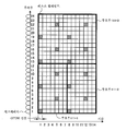
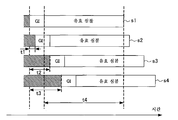
도 18은 멀티 패스 환경을 거쳐서 송신 장치로부터 수신 장치에 도달하는 신호의 개요를 도시하는 도면이다. 도 18에 있어서, 횡축은 시간이다. OFDM 심볼은, 유효 심볼과, 이 유효 심볼 전에 배치되고 상기 유효 심볼의 후반 부분을 카피하여 부가한 가드 인터벌에 의해 구성되어 있다.FIG. 18 is a diagram showing an outline of a signal arriving from a transmitter to a receiver through a multipath environment. FIG. In Fig. 18, the horizontal axis is time. An OFDM symbol is constituted by a valid symbol and a guard interval which is placed before the valid symbol and added by copying the second half of the valid symbol.
선행파 s1(최초에 도래한 파)과 동기를 취하고, 구간 t4에서 FFT 처리를 행한 경우에, 지연파 s2는 지연 시간이 가드 인터벌 이내의 지연 t1로 제한된 경우의 예를 나타내고 있으며, 지연파 s3 및 s4는 가드 인터벌을 초과하는 지연 t2 및 t3이 발생한 지연파를 나타내고 있다. 또한, 선행파, 지연파는, 도래파라고도 칭한다. 도 18의 사선부는 원하는 OFDM 심볼 전의 OFDM 심볼의 성분을 나타낸다.In the case of synchronizing with the preceding wave s1 (the wave first arrived) and performing the FFT process in the interval t4, the delay wave s2 shows an example in which the delay time is limited to the delay t1 within the guard interval, and the delay wave s3 And s4 represent delay waves in which delays t2 and t3 exceeding the guard interval have occurred. In addition, a preceding wave and a delayed wave are also called an arrival wave. 18 shows the components of an OFDM symbol before a desired OFDM symbol.
지연파 s3 및 s4에 대해서는, 그 전에 있는 사선부에 나타낸 바와 같이, 원하는 OFDM 심볼 전의 OFDM 심볼이 FFT 구간 t4 내에 들어가 있고, 심볼간 간섭(ISI: Inter-Symbol Interference)이 발생한다. 또한, 지연파 s3에서는, 구간 t4에 원하는 OFDM 심볼과 원하는 OFDM 심볼 전의 OFDM 심볼과의 이음매가 들어가게 되어, 캐리어간 간섭(ICI: Inter-Carrier Interference)이 발생한다. 지연파 s4에 있어서도, 마찬가지로, 구간 t4에 원하는 OFDM 심볼과 원하는 OFDM 심볼 전의 OFDM 심볼과의 이음매가 들어가서, 캐리어간 간섭이 발생한다.As for the delayed waves s3 and s4, as shown by the oblique portion before it, the OFDM symbol before the desired OFDM symbol is contained in the FFT period t4, and inter-symbol interference (ISI) occurs. In the delayed wave s3, a joint between a desired OFDM symbol and an OFDM symbol before the desired OFDM symbol enters the interval t4, and inter-carrier interference (ICI) occurs. In the delayed wave s4, similarly, the joint between the desired OFDM symbol and the OFDM symbol before the desired OFDM symbol enters the interval t4, and intercarrier interference occurs.
이들 심볼간 간섭, 캐리어간 간섭에 의한 특성 열화를 개선하기 위한 한 수법이 하기의 특허문헌 1, 특허문헌 2에 있어서 제안되어 있다. 이들 기술에서는, 수신 장치에 있어서, 한번 복조 동작을 행한 후에, 오류 정정 결과(MAP(Maximum A posteriori Probability: 최대 사후 확률) 복호기 출력)를 이용하여, 상기 심볼간 간섭 성분 및 상기 캐리어간 간섭 성분을 포함하는 원하는 것 이외의 서브캐리어의 복제 신호(간섭 레플리카 신호)를 작성한 후, 이것을 수신 신호로부터 제거한 신호에 대하여 MMSE(최소 평균 제곱 오차) 규범에 기초한 신호 등화 처리, 다시 복조 동작을 행하는 과정을 반복하여 행함으로써, 심볼간 간섭, 캐리어간 간섭에 의한 특성 열화의 개선을 행하고 있다. 이와 같이, 간섭 제거, 등화 처리 및 복호 처리를, 연판정 결과를 주고받으면서 반복하여 행하는 기술을 터보 등화라고 칭한다.One method for improving the deterioration of characteristics due to these intersymbol interference and intercarrier interference has been proposed in
그런데, 무선 통신 시스템에 있어서, OFDM을 사용한 다원 접속으로서, OFDMA(Orthogonal Frequency Division Multiple Access: 직교 주파수 분할 다원 접속)가 있다(예를 들어, 하기 비특허문헌 1 참조).By the way, in the wireless communication system, as a multiple connection using OFDM, there is Orthogonal Frequency Division Multiple Access (OFDMA) (see Non-Patent
도 19는, OFDMA에 있어서, 복수의 서브캐리어와 복수의 OFDM 심볼에 유저 1, 유저 2 및 유저 3의 데이터 변조 심볼을 할당하는 도면이며, 종축이 주파수, 횡축이 시간이다. 여기서, 하나의 서브캐리어와 하나의 OFDM 심볼로 이루어지는 단위를 리소스 엘리먼트라고 칭하고, 도 19에서는, 송신기는 336개의 리소스 엘리먼트에 배치된 데이터의 덩어리(송신 프레임이라 칭함)로 수신기에 데이터를 송신한다.19 is a diagram in which data modulation symbols of
도 19에 있어서는, 유저 1 및 유저 2는 각각 12개의 서브캐리어와 7개의 OFDM 심볼의 84개의 리소스 엘리먼트를 점유한다. 유저 3은 12개의 서브캐리어와 14개의 OFDM 심볼로 이루어지는 168개의 리소스 엘리먼트를 점유한다. 각 유저가 점유한 각 서브캐리어에는, 이들 유저가 송신하는 데이터 변조 심볼이 배치된다. 여기에서는, 각 유저는 상기 점유하는 리소스 엘리먼트를 하나의 블록으로 하여, 송신하는 정보 비트를 부호화하고 있다. 송신하는 상기 정보 비트를 부호화하는 단위를 부호화 블록(코딩 블록), 정보 비트를 부호화한 신호를 부호화 비트라고 칭한다. 그리고, 유저 1 및 유저 2의 부호화 블록은 84개의 리소스 엘리먼트에 배치되는 정보 비트로 이루어지고, 유저 3의 부호화 블록은 168개의 리소스 블록에 배치되는 정보 비트로 이루어진다. 즉, 도 19에서 도시된 OFDMA는, 송신 프레임이 복수의 부호화 블록으로 구성되고 또한 동일한 OFDM 심볼을 구성하는 서브캐리어에 다른 부호화 블록의 부호화 비트로부터 생성한 데이터 변조 심볼이 할당되어 있게 된다.In Fig. 19,
이 OFDMA에 있어서도, 가드 인터벌 구간을 초과하는 지연파가 존재하면, 심볼간 간섭, 캐리어간 간섭이 발생하여, 각 유저의 전송 특성이 열화된다.Also in this OFDMA, if a delay wave exceeding the guard interval period exists, inter-symbol interference and inter-carrier interference occur, resulting in deterioration of transmission characteristics of each user.
상기의 특허문헌 1 또는 특허문헌 2에 기재된 종래의 터보 등화 처리에서는, 동일한 OFDM 심볼을 구성하는 모든 서브캐리어에 배치된 데이터 변조 심볼에 대한 레플리카를 사용하여 터보 등화 처리를 행하고 있다. 따라서, 종래의 터보 등화 처리에서는, 송신 프레임이 복수의 부호화 블록으로 구성된 OFDMA 신호를 수신한 경우, 원하는 부호화 블록뿐만아니라, 원하지 않는 부호화 블록에 대해서도 부호화 비트 LLR로 대표되는 오류 정정 복호 결과를 산출하는 것이 필요해진다. 예를 들어, 유저 1의 수신 장치가, 도 19에 기재된 바와 같이, 3개의 유저가 할당된 OFDMA 신호를 수신하고, 제2 OFDM 심볼에 대하여 터보 등화 처리를 행하는 경우, 상기 제2 OFDM 심볼에 대한 심볼간 간섭 레플리카를 생성하기 위해서는, 유저 1에 대한 신호의 복호 결과와 원하지 않는 신호인 유저 3에 대한 신호의 복호 결과로부터 변조 심볼 레플리카를 생성할 필요가 있다. 결과로서, 다른 유저의 신호(원하지 않는 부호화 블록)에 대한 오류 정정 복호 처리가 수신기의 신호 처리의 효율을 저하시킨다는 문제를 발생시키게 된다.In the conventional turbo equalization process described in
본 발명은 상기 문제를 감안하여 이루어진 것으로서, 그의 목적은, 가드 인터벌 구간을 초과하는 지연파가 존재하는 환경 하에서 복수의 유저의 데이터 신호가 배치된 멀티 캐리어 신호를 수신한 경우에 있어서, 복수의 유저의 부호화 블록의 비트수가 상이함으로써 터보 등화 처리 시간을 연장시키는 일 없이, 심볼간 간섭, 서브캐리어간 간섭을 제거하여, 전송 특성을 개선할 수 있는 수신 장치 및 수신 방법을 제공하는 데에 있다.SUMMARY OF THE INVENTION The present invention has been made in view of the above problems, and an object thereof is to provide a plurality of users when receiving a multicarrier signal in which data signals of a plurality of users are arranged under an environment in which delay waves exceeding a guard interval interval exist. The present invention provides a receiving apparatus and a receiving method which can improve the transmission characteristics by eliminating inter-symbol interference and inter-carrier interference without extending the turbo equalization processing time by varying the number of bits of the coding block.
본 발명의 1 관점에 의하면, 멀티 캐리어 변조된 신호를 수신하는 수신부와, 복호 처리 결과를 사용하여 생성한 변조 심볼 레플리카를 상기 수신부가 수신한 신호로부터 제거하여 출력하는 간섭 제거부와, 상기 간섭 제거부에 의해 출력한 신호를 복호 처리하여 복호 처리 결과를 출력하는 신호 검출부를 구비하고, 상기 간섭 제거부는 상기 변조 심볼 레플리카를, 상기 수신부가 수신한 신호를 구성하는 데이터 변조 심볼의 일부에 대한 복호 처리 결과를 사용하여 생성하는 것을 특징으로 하는 수신 장치가 제공된다. 상기 간섭 제거부는 상기 수신부가 수신한 신호를 구성하는 데이터 변조 심볼의 일부에 대한 변조 심볼 레플리카를 사용하여 간섭 제거하는 것이 바람직하다.According to one aspect of the present invention, there is provided a receiver for receiving a multicarrier modulated signal, an interference canceller for removing and outputting a modulation symbol replica generated using a decoding process result from the signal received by the receiver, and the interference agent. A signal detector which decodes the signal output by rejection and outputs a decoding process result, wherein the interference canceling unit performs decoding processing on a part of data modulation symbols constituting a signal received by the reception symbol replica; A receiving device is provided which generates using the result. Preferably, the interference canceling unit removes interference by using a modulation symbol replica for a part of data modulation symbols constituting a signal received by the receiver.
상기 수신부는 복수의 부호화 블록의 부호화 비트로 생성한 데이터 변조 심볼로 구성되는 멀티 캐리어 변조한 신호를 수신하고, 상기 간섭 제거부는 상기 변조 심볼 레플리카를 상기 부호화 블록 중 적어도 1개의 부호화 블록에 대한 데이터 변조 심볼의 복호 처리 결과를 사용하여 생성하는 것이 바람직하다. 상기 멀티 캐리어 변조한 신호는 상기 부호화 블록이 유저마다 할당되어 있는 신호인 것이 바람직하다. 상기 신호 검출부는 상기 간섭 제거부에 의해 출력한 신호 중, 원하는 데이터 변조 심볼만에 대한 복호 처리를 행하고 그 복호 처리 결과를 출력하는 것이 바람직하다.The receiving unit receives a multi-carrier modulated signal consisting of data modulation symbols generated by coded bits of a plurality of coding blocks, and the interference canceling unit converts the modulation symbol replica into data modulation symbols for at least one coded block among the coding blocks. It is preferable to generate using the result of the decoding process of. Preferably, the multicarrier modulated signal is a signal to which the coding block is assigned for each user. It is preferable that the signal detection unit performs decoding processing on only desired data modulation symbols among the signals output by the interference cancellation unit, and outputs the decoding processing result.
상기 간섭 제거부에 의해 출력한 신호를 복조하는 복조부를 구비하고, 상기 간섭 제거부는 상기 변조 심볼 레플리카를, 상기 수신부가 수신한 신호를 구성하는 데이터 변조 심볼의 일부의 데이터 변조 심볼의 복호 처리 결과와 그 밖의 일부의 데이터 변조 심볼의 상기 복조부의 복조 처리 결과를 사용하여 생성하는 것이 바람직하다. 상기 수신부는 복수의 부호화 블록의 부호화 비트로 생성한 데이터 변조 심볼로 구성되는 멀티 캐리어 변조한 신호를 수신하고, 상기 간섭 제거부는 상기 변조 심볼 레플리카를 복수의 부호화 블록 중 적어도 1개의 부호화 블록에 대한 변조 심볼의 복호 처리 결과와 상기 부호화 블록을 제외한 적어도 1개의 부호화 블록에 대한 데이터 변조 심볼의 복조 결과를 사용하여 생성하는 것이 바람직하다.And a demodulator for demodulating the signal output by the interference canceller, wherein the interference canceler is configured to perform a decoding process on a data modulation symbol of a part of data modulation symbols constituting a signal received by the receiver. It is preferable to generate by using the demodulation process result of the said demodulation part of other data modulation symbols. The receiving unit receives a multicarrier modulated signal consisting of data modulation symbols generated by coded bits of a plurality of coding blocks, and the interference canceling unit modulates the modulation symbol replica for at least one coded block among a plurality of coding blocks. It is preferable to generate using the result of decoding processing and the result of demodulation of data modulation symbols for at least one coded block except for the coded block.
또한, 상기 간섭 제거부는 복호 처리 결과를 사용하여 변조 심볼 레플리카를 생성하는 심볼 레플리카 생성부와, 상기 변조 심볼 레플리카와 전반로 추정값을 사용하여 간섭 레플리카를 생성하는 간섭 레플리카 생성부와, 상기 수신부가 수신한 신호로부터 상기 간섭 레플리카를 감산하는 감산부를 구비하는 것이 바람직하다.The interference canceling unit may further include a symbol replica generation unit generating a modulation symbol replica using a decoding processing result, an interference replica generation unit generating an interference replica using the modulation symbol replica and a propagation path estimate, and the receiver receiving It is preferable to have a subtraction section for subtracting the interference replica from one signal.
본 발명의 다른 관점에 의하면, 멀티 캐리어 변조한 신호를 수신하는 제1 스텝과, 복호 처리 결과를 사용하여 생성한 변조 심볼 레플리카를 상기 제1 스텝에 의해 수신한 신호로부터 제거하여 출력하는 제2 스텝과, 상기 제2 스텝에 의해 출력한 신호를 복호 처리하여 복호 처리 결과를 출력하는 제3 스텝을 갖고, 상기 제2 스텝은 상기 변조 심볼 레플리카를, 수신부가 수신한 신호를 구성하는 데이터 변조 심볼의 일부에 대한 복호 처리 결과를 사용하여 생성하는 스텝을 포함하는 것이 바람직하다.According to another aspect of the present invention, there is provided a first step of receiving a multicarrier modulated signal, and a second step of removing and outputting a modulation symbol replica generated using the decoding processing result from the signal received by the first step. And a third step of decoding the signal output by the second step and outputting a decoding process result, wherein the second step includes the modulation symbol replica of the data modulation symbol constituting the signal received by the receiver. It is preferable to include the step of generating using the result of the decoding process for a part.
또한, 본 발명은 멀티 캐리어 변조한 신호를 송신하는 송신 장치와, 상기 송신 장치에 의해 송신된 신호를 수신하여 복호하는 수신 장치를 구비하는 통신 시스템으로서, 상기 수신 장치는 상기 송신 장치에 의해 송신된 신호를 수신하는 수신부와, 복호 처리 결과를 사용하여 생성한 변조 심볼 레플리카를 상기 수신부가 수신한 신호로부터 제거하여 출력하는 간섭 제거부와, 상기 간섭 제거부에 의해 출력한 신호를 복호 처리하여 복호 처리 결과를 출력하는 신호 검출부를 구비하고, 상기 간섭 제거부는 상기 변조 심볼 레플리카를, 수신부가 수신한 신호를 구성하는 데이터 변조 심볼의 일부에 대한 복호 처리 결과를 사용하여 생성하는 것을 특징으로 하는 통신 시스템이다.In addition, the present invention is a communication system comprising a transmitting device for transmitting a multicarrier modulated signal and a receiving device for receiving and decoding a signal transmitted by the transmitting device, wherein the receiving device is transmitted by the transmitting device. A receiver for receiving a signal, an interference canceler for removing and outputting a modulation symbol replica generated using a decoding processing result from the signal received by the receiver, and a decoding process for decoding the signal output by the interference canceler And a signal detector for outputting a result, wherein the interference canceling unit generates the modulation symbol replica using a result of decoding processing on a part of data modulation symbols constituting a signal received by the receiver. .
또한, 본 발명은 멀티 캐리어 변조한 신호를 송신하는 스텝과, 상기 송신 장치에 의해 송신된 신호를 수신하여 복호하는 스텝을 갖는 통신 방법으로서, 상기 수신하여 복호하는 스텝은, 멀티 캐리어 변조한 신호를 수신하는 제1 스텝과, 복호 처리 결과를 사용하여 생성한 변조 심볼 레플리카를 상기 제1 스텝에 의해 수신한 신호로부터 제거하여 출력하는 제2 스텝과, 상기 제2 스텝에 의해 출력한 신호를 복호 처리하여 복호 처리 결과를 출력하는 제3 스텝을 갖고, 상기 제2 스텝은 상기 변조 심볼 레플리카를, 수신부가 수신한 신호를 구성하는 데이터 변조 심볼의 일부에 대한 복호 처리 결과를 사용하여 생성하는 것을 특징으로 하는 통신 방법이다.In addition, the present invention provides a communication method having a step of transmitting a multicarrier modulated signal and a step of receiving and decoding a signal transmitted by the transmitting apparatus, wherein the step of receiving and decoding a multicarrier modulated signal. Decoding process of the 1st step of receiving, the 2nd step of removing and outputting the modulation symbol replica produced | generated using the decoding process result from the signal received by the said 1st step, and the signal output by the said 2nd step And a third step of outputting a decoding process result, wherein the second step generates the modulation symbol replica using a decoding process result for a part of data modulation symbols constituting a signal received by a receiver. Is a communication method.
또한, 본 발명은 복호 처리 결과를 사용하여 생성한 변조 심볼 레플리카를 수신한 멀티 캐리어 변조한 신호로부터 제거하여 출력하는 간섭 제거 회로와, 상기 간섭 제거 회로에 의해 출력한 신호를 복호 처리하여 복호 처리 결과를 출력하는 신호 검출 회로와, 적어도 상기 간섭 제거 회로에 대하여 제어를 행하는 칩 제어 회로를 갖고, 상기 간섭 제거 회로는, 상기 변조 심볼 레플리카를, 수신부가 수신한 신호를 구성하는 데이터 변조 심볼의 일부에 대한 복호 처리 결과를 사용하여 생성하는 회로를 포함하는 것을 특징으로 하는 수신 회로이다.The present invention also provides an interference cancellation circuit for removing and outputting a modulation symbol replica generated using the decoding processing result from the received multicarrier modulated signal, and a decoding processing result by decoding the signal output by the interference cancellation circuit. And a chip control circuit for controlling at least the interference canceling circuit, the interference canceling circuit including the modulation symbol replica as a part of the data modulation symbols constituting the signal received by the receiver. And a circuit for generating using the result of the decoding process.
또한, 본 발명은 상기의 통신 방법을 컴퓨터에 실행시키기 위한 프로그램이어도 되고, 상기 프로그램을 기록하는 컴퓨터 판독 가능한 기록 매체여도 된다. 상기 프로그램은 인터넷 등의 전송 매체를 개재하여 취득한 것이어도 된다.The present invention may be a program for causing a computer to execute the above communication method, or may be a computer-readable recording medium for recording the program. The program may be acquired via a transmission medium such as the Internet.
본 명세서는 본원의 우선권의 기초인 일본 특허 출원 제2009-246037호의 명세서 및/또는 도면에 기재되는 내용을 포함한다.This specification includes content described in the specification and / or drawings of Japanese Patent Application No. 2009-246037, which is a priority document of the present application.
본 발명에 따르면, 가드 인터벌 구간을 초과하는 지연파가 존재하는 환경 하에서 복수의 부호화 블록의 데이터 신호가 배치된 멀티 캐리어 신호를 수신한 경우, 원하는 부호화 블록의 이외의 부호화 블록에 대한 간섭 레플리카 생성의 부하를 삭감할 수 있고, 수신기의 신호 처리의 효율 저하를 개선할 수 있다.According to the present invention, when receiving a multicarrier signal in which data signals of a plurality of coding blocks are arranged in an environment in which delay waves exceeding a guard interval period exist, interference replica generation for coded blocks other than a desired coding block is performed. The load can be reduced and the efficiency degradation of the signal processing of the receiver can be improved.
특히, 송신 프레임 내에 배치된 원하지 않는 부호화 블록의 부호화 비트로부터 생성한 데이터 변조 심볼의 배치에 의존하지 않고, 원하는 부호화 블록에 대한 심볼간 간섭, 서브캐리어간 간섭을 터보 등화 처리에 의해 효율적으로 제거하여 전송 특성을 개선할 수 있다. 또한, 원하지 않는 부호화 블록의 부호화 비트수에 의존하지 않고, 원하는 부호화 블록의 부호화 비트수에 기초하여 터보 등화 처리를 행할 수 있어 전송 특성을 개선할 수 있다.In particular, it is possible to efficiently remove the inter-symbol interference and the sub-carrier interference for a desired coding block by turbo equalization processing, without depending on the arrangement of data modulation symbols generated from the coding bits of the unwanted coding block disposed in the transmission frame. It is possible to improve the transmission characteristics. Further, the turbo equalization process can be performed based on the number of coding bits of the desired coding block without depending on the number of coding bits of the unwanted coding block, thereby improving the transmission characteristics.
도 1은 본 발명의 제1 실시 형태에 따른 송신 장치(100)의 일 구성예를 도시하는 기능 블록도이다.
도 2는 심볼 생성부에서 입력되는 유저 n의 데이터 변조 심볼과 파일럿 심볼을 IFFT부의 입력 포인트에 맵핑한 예를 도시하는 도면이다.
도 3은 본 발명의 제1 실시 형태에 따른 수신 장치의 일 구성예를 도시하는 개략 블록도이다.
도 4는 간섭 제거부의 일 구성예를 도시하는 기능 블록도이다.
도 5는 레플리카 생성부의 일 구성예를 도시하는 기능 블록도이다.
도 6은 수신 장치의 동작을 설명하는 흐름도이다.
도 7은 본 발명의 제2 실시 형태에 따른 수신 장치의 일 구성예를 도시하는 기능 블록도이다.
도 8은 간섭 제거부의 일 구성예를 도시하는 기능 블록도이다.
도 9는 레플리카 생성부의 일 구성예를 도시하는 기능 블록도이다.
도 10은 수신 장치의 동작을 설명하는 흐름도이다.
도 11은 복수 유저의 데이터 변조 심볼과 파일럿 심볼이 리소스 엘리먼트에 맵핑된 다른 예를 도시하는 도면이다.
도 12는 복수 유저의 데이터 변조 심볼과 파일럿 심볼이 리소스 엘리먼트에 맵핑된 다른 예를 도시하는 도면이다.
도 13은 본 발명의 제3 실시 형태에 따른 송신 장치의 일 구성예를 도시하는 기능 블록도이다.
도 14는 심볼 생성부에서 입력되는 유저 1의 데이터 변조 심볼과 파일럿 심볼을 IFFT부의 입력 포인트에 맵핑한 예를 도시하는 도면이다.
도 15는 본 발명의 제3 실시 형태에 따른 수신 장치의 일 구성예를 도시하는 기능 블록도이다.
도 16은 간섭 제거부의 일 구성예를 도시하는 기능 블록도이다.
도 17은 수신 장치의 동작을 설명하는 흐름도이다.
도 18은 멀티 패스 환경을 거쳐서 송신 장치로부터 수신 장치에 도달하는 신호의 개요를 도시하는 도면이다.
도 19는 OFDMA에 있어서, 복수의 서브캐리어와 복수의 OFDM 심볼에 유저 1, 유저 2 및 유저 3의 데이터 변조 심볼을 할당하는 도면이며, 종축이 주파수, 횡축이 시간이다.
[부호의 설명]
100: 송신 장치
101: 안테나
102-1 내지 N: 심볼 생성부
111-1 내지 N: 부호부
103: IFFT부
104: GI 삽입부
105: 송신부
200: 수신 장치
201: 안테나
202: 수신부
203: 수신 신호 기억부
204: 간섭 제거부
205: GI 제거부
206: FFT부
207: 전반로 보상부
208-1: 신호 검출부
209: 전반로 추정부
221-1: 복조부
222-1: 디인터리브부
223-1: 복호부1 is a functional block diagram showing an example of a configuration of a
FIG. 2 is a diagram illustrating an example in which data modulation symbols and pilot symbols of user n inputted from the symbol generator are mapped to input points of the IFFT unit.
3 is a schematic block diagram showing an example of the configuration of a receiving apparatus according to the first embodiment of the present invention.
4 is a functional block diagram illustrating an example of a configuration of an interference cancellation unit.
5 is a functional block diagram illustrating an example of a configuration of a replica generating unit.
6 is a flowchart illustrating the operation of the receiving device.
7 is a functional block diagram illustrating an example of a configuration of a receiving apparatus according to a second embodiment of the present invention.
8 is a functional block diagram illustrating an example of a configuration of an interference cancellation unit.
9 is a functional block diagram illustrating an example of a configuration of a replica generating unit.
10 is a flowchart for explaining the operation of the receiving device.
11 is a diagram illustrating another example in which data modulation symbols and pilot symbols of a plurality of users are mapped to resource elements.
12 is a diagram illustrating another example in which data modulation symbols and pilot symbols of a plurality of users are mapped to resource elements.
It is a functional block diagram which shows an example of a structure of the transmission apparatus which concerns on 3rd Embodiment of this invention.
FIG. 14 is a diagram illustrating an example in which data modulation symbols and pilot symbols of
15 is a functional block diagram illustrating an example of a configuration of a receiving apparatus according to a third embodiment of the present invention.
16 is a functional block diagram illustrating an example of a configuration of an interference cancellation unit.
17 is a flowchart illustrating the operation of the receiving device.
FIG. 18 is a diagram showing an outline of a signal arriving from a transmitter to a receiver through a multipath environment. FIG.
19 is a diagram in which data modulation symbols of
[Description of Symbols]
100: transmitting device
101: antenna
102-1 to N: symbol generator
111-1 to N: code part
103: IFFT unit
104: GI insertion portion
105: transmitter
200: receiving device
201: antenna
202: receiver
203: reception signal storage unit
204: interference cancellation unit
205: GI removal unit
206: FFT section
207: General Road Compensation Unit
208-1: signal detector
209: propagation estimator
221-1: Demodulator
222-1: deinterleave
223-1: Decryptor
이하, 본 발명의 실시 형태에 대해서 상세하게 설명한다.EMBODIMENT OF THE INVENTION Hereinafter, embodiment of this invention is described in detail.
(제1 실시 형태)(1st embodiment)
본 발명의 실시 형태에서는, 송신 장치가 직교하는 멀티 캐리어에 있어서 복수의 유저가 주파수 다원 접속되어 있는 OFDMA의 신호를 송신하는 경우를 예로 하여 설명한다.In the embodiment of the present invention, a case where a plurality of users transmit a signal of OFDMA in which a plurality of users are frequency-multiplexed in a multicarrier orthogonal to each other will be described as an example.
본 발명의 제1 실시 형태에 의한 통신 시스템은, 복수 유저의 신호가 할당된 OFDMA 신호(멀티 캐리어 변조한 신호)를 송신하는 송신 장치(100)와 송신 장치(100)가 송신한 신호를 수신하는 수신 장치(200)로 구성된다. 이하에서는, 송신 장치(100)는 셀룰러 시스템의 다운링크에 있어서의 기지국에 설치되고, 수신 장치(200)는 기지국에 링크하고 있는 복수의 이동 단말기 중 1개의 이동 단말기에 탑재되어 있는 경우를 예로 하여 설명한다.The communication system according to the first embodiment of the present invention receives a signal transmitted by the transmitting
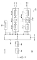
도 1은 본 발명의 제1 실시 형태에 따른 송신 장치(100)의 일 구성예를 도시하는 기능 블록도이다. 송신 장치(100)는 심볼 생성부(102-1 내지 102-N), IFFT(역고속 푸리에 변환)부(103), GI 삽입부(104), 송신부(105) 및 파일럿 생성부(106)를 포함하여 구성되고, 송신부(105)에 안테나부(101)가 접속되어 있다. 또한, N은 송신 장치(100)가 배치된 기지국에 링크할 수 있는 유저수이다.1 is a functional block diagram showing an example of a configuration of a
심볼 생성부(102-n)(n=1, 2, ···, N)는 기지국의 송신 장치(100)로부터 유저 n에 송신하는 신호를 생성한다. 심볼 생성부(102-n)는 부호부(111-n), 인터리브부(112-n), 변조부(113-n)를 구비하고 있다.The symbol generation unit 102-n (n = 1, 2, ..., N) generates a signal to be transmitted from the transmitting
심볼 생성부(102-n)에는, MAC(Media Access Control, 매체 액세스 제어)부 등(도 1에는 도시하지 않는다. MAC부 등이란 MAC층, 네트워크층 등의 상위층에 위치하는 기능을 말함)으로부터 입력된 유저 n에 송신하는 정보 비트가 입력된다. 또한, 정보 비트란 압축 부호화된 음성 신호, 영상 신호, 그 밖의 데이터 신호를 「0」, 「1」로 나타낸 신호이다. 부호부(111-n)는 입력된 유저 n의 정보 비트에 대하여 터보 부호, LDPC(Low Density Parity Check: 저밀도 패리티 검사), 컨벌루션 부호 등 중의 어느 하나의 오류 정정 부호화 처리를 행한다. 즉, 유저마다 다른 부호화 블록에서 부호화하고 있다.The symbol generation unit 102-n includes a MAC (Media Access Control) unit or the like (not shown in Fig. 1. The MAC unit or the like refers to a function located at a higher layer such as a MAC layer or a network layer). The information bits to be transmitted to the input user n are input. The information bits are signals represented by "0" and "1" for compression-encoded audio signals, video signals, and other data signals. The code part 111-n performs an error correction coding process of any one of a turbo code, a Low Density Parity Check (LDPC), a convolutional code, and the like, on the input information bit of the user n. In other words, coding is performed in different coding blocks for different users.
인터리브부(112-n)는 주파수 선택성 페이딩에 의한 수신 전력의 저조에 기인하는 버스트 오류가 발생하는 것을 개선하기 위해서, 부호부(111-n)로부터 출력되는 유저 n의 부호화 비트의 정렬 순서를 교체한다. 변조부(113-n)는 인터리브부(112-n)가 출력하는 유저 n의 부호화 비트를 맵핑하고, BPSK(Binary Phase Shift Keying: 2상 위상 편이 변조), QPSK(Quadrature Phase Shift Keying: 4상 위상 편이 변조), 16QAM(16 Quadrature Amplitude Modulation: 16값 직교 진폭 변조), 64QAM(64 Quadrature Amplitude Modulation: 64값 직교 진폭 변조) 등의 데이터 변조 심볼을 생성한다.The interleaving section 112-n replaces the order of the coding bits of the user n coded bits output from the sign section 111-n in order to improve the occurrence of a burst error due to a low reception power caused by frequency selective fading. do. The modulator 113-n maps the coded bits of the user n outputted by the interleaver 112-n, and performs binary phase shift keying (BPSK) and quadrature phase shift keying (QPSK). Data modulation symbols such as phase shift modulation, 16 Quadrature Amplitude Modulation (16QAM), and 64 Quadrature Amplitude Modulation (64 QAM) are generated.
파일럿 생성부(106)는 수신 장치에 있어서 전반로를 추정할 수 있는 파일럿 심볼을 생성한다. 파일럿 심볼은 송신 장치(100)가 설치된 기지국에 링크하고 있는 이동 단말기(유저)에 공통이어도 되고, 유저마다 규정되어 있어도 된다. 파일럿 심볼을 구성하는 부호 계열은, 아다마르 부호, CAZAC(Constant Amplitude Zero Auto-Correlation) 계열 등의 직교한 계열인 것이 바람직하다.The
IFFT부(103)는 MAC부 등(도시 생략)으로부터 통지되는 신호 할당 정보에 기초하여, 심볼 생성부(102-n)로부터 입력되는 유저 n의 데이터 변조 심볼과 파일럿 심볼을 IFFT 입력 포인트에 맵핑하고(서브캐리어 맵핑), IFFT 처리를 행함으로써, 각각의 심볼을 주파수 영역의 신호로부터 시간 영역의 신호로 변환한다. 또한, 이하에서는, 설명의 간소화를 위해서 IFFT 포인트수와 서브캐리어수가 동일한 것으로 설명하는데, 이것에 한정하는 취지는 아니다. IFFT 포인트수가 서브캐리어수가 이하여도 되고, 서브캐리어수가 IFFT 포인트수 이상이면, IFFT부를 복수개 구비할 수 있다.The
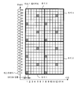
도 2는 심볼 생성부(102-n)로부터 입력되는 유저 n의 데이터 변조 심볼과 파일럿 심볼을 IFFT부(103)의 입력 포인트에 맵핑한 예를 도시하는 도면이다. 도 2는 24개의 서브캐리어수와 14개의 OFDM 심볼로 구성된 송신 프레임에 3개의 유저 및 파일럿 심볼을 할당한 경우를 나타내고 있다. 제1번째의 OFDM 심볼의 제k번째의 서브캐리어의 리소스 엘리먼트를 (k, 1)로 한다.FIG. 2 is a diagram showing an example in which data modulation symbols and pilot symbols of user n inputted from the symbol generator 102-n are mapped to input points of the
도 2에서는 파일럿 심볼을 리소스 엘리먼트 (Kp, Lp)=(1, 1), (7, 1), (13, 1), (19, 1), (4, 5), (10, 5), (16, 5), (22, 5), (1, 8), (7, 8), (13, 8), (19, 8), (4, 12), (10, 12), (16, 12), (22, 12)에 배치하고 있다(사선의 리소스 엘리먼트가 상당함). 유저 1에 송신하는 데이터 변조 심볼은 리소스 엘리먼트(K1, L1), (K1=1…12, L1=1…7, 단, 파일럿 심볼을 배치한 리소스 엘리먼트는 제외함)에 배치된다. 유저 2에 송신하는 데이터 변조 심볼은 리소스 엘리먼트(K2, L2), (K2=1, …, 12, L2=8, …, 14, 단, 파일럿 심볼을 배치한 리소스 엘리먼트는 제외함)에 배치된다. 유저 3에 송신하는 데이터 변조 심볼은 리소스 엘리먼트(K3, L3), (K3=13, …, 24, L3=1, …, 14, 단, 파일럿 심볼을 배치한 리소스 엘리먼트는 제외함)에 배치된다. 따라서, 예를 들어, 제1 OFDM 심볼에 대한 IFFT 처리에서는, IFFT 입력 포인트의 제1, 7, 13, 19번째로 파일럿 심볼을 맵핑하고, 제1부터 제12번째까지(파일럿 심볼이 맵핑한 IFFT 입력 포인트는 제외함)에 유저 1의 데이터 변조 심볼을 맵핑하고, 제13부터 제24번째까지(파일럿 심볼이 맵핑한 IFFT 입력 포인트는 제외함)에 유저 2의 데이터 변조 심볼을 맵핑한다.In FIG. 2, the pilot symbols include resource elements (Kp, Lp) = (1, 1), (7, 1), (13, 1), (19, 1), (4, 5), (10, 5), (16, 5), (22, 5), (1, 8), (7, 8), (13, 8), (19, 8), (4, 12), (10, 12), (16 , 12) and (22, 12) (the diagonal resource elements are equivalent). The data modulation symbols transmitted to
각 유저의 데이터 변조 심볼을 맵핑하는 리소스 엘리먼트는 신호 할당 정보에 의해 통지된다. 신호 할당 정보가 통지하는 리소스 엘리먼트는 송신 장치(100)를 구비한 기지국과 각 유저의 이동 단말기 사이의 전반로 상황 및 기지국이 각 유저의 이동 단말기에 송신하는 데이터량 등에 기초하여 결정된다. 이 데이터 변조 심볼을 맵핑하는 리소스 엘리먼트를 결정하는 것을 스케줄링이라 칭한다.The resource element that maps the data modulation symbol of each user is notified by the signal assignment information. The resource element notified by the signal allocation information is determined based on the propagation path situation between the base station provided with the transmitting
신호 할당 정보는 상기 유저의 데이터 변조 심볼이 할당된 OFDA 심볼과 동일한 OFDM 심볼, 또는 상기 유저의 데이터 변조 심볼이 할당된 송신 프레임과 동일한 송신 프레임으로 유저에게 통지해도 되고, 다른 OFDM 심볼 또는 다른 송신 프레임으로 통지해도 된다.The signal allocation information may be notified to the user by the same OFDM symbol as the OFDA symbol to which the user's data modulation symbol is assigned, or the same transmission frame as the transmission frame to which the user's data modulation symbol is assigned, or another OFDM symbol or another transmission frame. You may also notify.
또한, 도 2에서는, OFDMA를 구성하는 리소스 엘리먼트에 유저에 송신하는 데이터 변조 심볼 및 파일럿 심볼을 맵핑하고 있지만, 각 유저에 대한 제어 신호를 포함해도 된다.In addition, although the data modulation symbol and pilot symbol which are transmitted to a user are mapped to the resource element which comprises OFDMA in FIG. 2, you may also contain the control signal for each user.
도 1로 돌아가서, GI 삽입부(104)는 IFFT부(103)가 변환한 시간 영역의 신호에 가드 인터벌(GI)을 부가한다. 예를 들어, IFFT부(103)가 출력하는 시간 영역의 신호(유효 심볼)의 후반의 일부를 카피하고, 유효 심볼의 선두에 부가한다. GI를 부가한 유효 심볼을 OFDM 심볼이라 칭한다. GI 삽입부(104)가 출력하는 신호를 s(t)라 하면, 다음 수학식 1로 나타낼 수 있다.Returning to FIG. 1, the

단, Nf는 IFFT 포인트수, ck, 1은 제1번째의 OFDM 심볼의 제k 서브캐리어에 할당된 심볼, Δf는 서브캐리어 간격, Ts는 OFDM 심볼 길이(GI 길이를 포함함), j는 허수 단위이다.Where Nf is the number of IFFT points, ck, 1 is the symbol allocated to the kth subcarrier of the first OFDM symbol, Δf is the subcarrier spacing, Ts is the OFDM symbol length (including the GI length), and j is an imaginary number Unit.
송신부(105)는 GI 삽입부(104)가 출력하는 OFDM 심볼을 아날로그 신호로 변환하고(Digital to Analog 변환하고), 아날로그 신호로 변환된 신호에 대하여 대역제한을 행하는 필터링 처리를 행하고, 또한 필터링 처리된 신호를 송신 가능한 주파수 대역으로 업 컨버트하고, 안테나부(101)를 통하여 송신한다. 이 송신 장치(100)가 출력하는 신호를 OFDMA 신호라고 칭한다.The
상술에서는, 본 실시 형태에 있어서의 수신 장치(200)가 수신하는 OFDMA 신호에 복수 유저의 데이터 변조 심볼이 할당되고, 데이터 변조 심볼은 유저마다 정보 비트를 부호화한 부호화 비트로 구성되어 있는 경우를 예로 하여 설명했지만, 데이터 변조 심볼을 동일 유저에 대한 정보 비트를 복수의 부호부에서 부호화한 부호화 비트로 구성하는 경우에 있어서도 적용 가능하다. 즉, 도 2에 있어서의 유저 1 내지 유저 3 각각이 점유한 리소스 엘리먼트를 유저 1이 모두 점유하고, 유저 1이 점유한 리소스 엘리먼트에 할당하는 데이터 변조 심볼을 구성하는 정보 비트가 (K1, L1), (K2, L2), (K3, L3)으로 나뉘어서 부호화되어 있는 경우에 있어서도 본 실시 형태의 기술을 적용하는 것이 가능하다.In the above description, a case where a data modulation symbol of a plurality of users is allocated to an OFDMA signal received by the
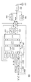
도 3은 본 발명의 제1 실시 형태에 따른 수신 장치(200)의 일 구성예를 도시하는 개략 블록도이다. 수신 장치(200)는 송신 장치(100)가 송신하는 신호를 수신하는 유저 1의 이동 단말기에 탑재되어 있는 것으로서 설명한다. 또한, 유저 n(n=2, ···, N)의 이동 단말기에 탑재되는 수신 장치도, 적어도 동일한 기능을 갖는 것이 가능하다.3 is a schematic block diagram showing an example of the configuration of a receiving
수신 장치(200)는 수신부(202), 수신 신호 기억부(203), 간섭 제거부(204), GI 제거부(205), FFT부(206), 전반로 보상부(207), 서브캐리어 디맵핑부(210), 신호 검출부(208-1), 전반로 추정부(209)를 구비하고, 수신부(202)에 안테나부(201)가 접속되어 있다. 또한, 상기 수신 장치(200)의 일부 또는 전부를 칩화하여 집적 회로가 되는 경우, 각 기능 블록에 대하여 제어를 행하는 칩 제어 회로(211)를 갖는다.The
수신 장치(200)에 있어서, 수신부(202)는 안테나부(201)를 통하여 송신 장치(100)로부터 송신된 OFDMA 신호를 수신하면, 신호 검출 처리 등의 디지털 신호 처리가 가능한 주파수대로 다운 컨버트하고, 또한 스퓨리어스를 제거하는 필터링 처리를 행하고, 필터링 처리한 신호를 아날로그 신호로부터 디지털 신호로 변환(Analog to Digital 변환)을 행하고, 수신 신호 기억부(203), 간섭 제거부(204) 및 전반로 추정부(209)에 출력한다.In the
전반로 추정부(209)는 송신 장치(100)와 수신 장치(200)의 사이에 있어서의 페이딩 등에 의한 진폭과 위상의 변동을 추정하는 전반로 추정을 행하고, 전반로 추정 결과인 전반로 추정값을 간섭 제거부(204)와 전반로 보상부(207)에 출력한다. 전반로 추정은, 예를 들어, 수신부(202)가 출력하는 신호에 포함되는 기지의 신호인 파일럿 심볼을 사용하여 행할 수 있다. 도 2에 기재한 OFDMA 신호를 수신한 경우, 수신한 OFDMA 신호를 주파수 영역으로 변환한 신호이며, 파일럿 심볼을 할당한 서브캐리어의 신호(리소스 엘리먼트(Kp, Lp)=(1, 1), (7, 1), (13, 1), (19, 1), (4, 5), (10, 5), (16, 5), (22, 5), (1, 8), (7, 8), (13, 8), (19, 8), (4, 12), (10, 12), (16, 12), (22, 12) 중 1 또는 2 이상의 신호 성분)를 사용하여 주파수 응답을 산출한다. 파일럿 심볼을 배치한 서브캐리어 이외의 서브캐리어의 주파수 응답은 파일럿 심볼을 배치한 서브캐리어의 주파수 응답을 사용하여, 선형 보간, FFT 보간 등의 보간 기술에 의해 산출할 수 있다.The
또한, 전반로 추정은 신호 검출부(208-1)가 출력하는 복호 결과를 사용하는 반복 전반로 추정을 적용하는 것도 가능하다.In addition, it is also possible to apply iterative propagation path estimation using the decoding result output from the signal detector 208-1.
수신 신호 기억부(203)는 수신부(202)가 출력하는 신호를 기억한다. 또한, 간섭 제거부(204)의 간섭 제거 처리에 있어서, 반복 처리가 행하여지는 경우, 저장하고 있는 이 신호를 출력한다.The reception
간섭 제거부(204)는 전반로 추정부(209)로부터 출력되는 전반로 추정값, 신호 검출부(208-1)로부터 출력되는 복호 결과를 사용하여, 수신부(202) 또는 수신 신호 기억부(203)로부터 출력되는 신호로부터, 간섭 성분을 제거하는 처리를 반복하여 행한다. 구체적으로는, 신호 검출부(208-1)가 출력하는 복호 후의 부호화 비트의 대수 우도비 LLR(Log Likelihood Ratio)을 사용하여, 수신한 신호의 송신원인 송신 장치(100)가 자(自)수신 장치에 송신했을 것인 신호 레플리카를 생성한다. 즉, 수신 장치(200)에서는 송신 장치(100)가 송신한 유저 1에 대한 송신 신호 레플리카를 생성한다. 또한, 이 송신 신호 레플리카와 전반로 추정부(209)로부터의 전반로 추정값을 사용하여 유저 1에 대한 간섭 레플리카를 생성하고, 수신부(202) 또는 수신 신호 기억부(203)로부터 출력되는 신호로부터 감산한다. 따라서, 간섭 제거부(204)는 수신한 OFDMA 신호를 구성하는 데이터 변조 심볼 중, 일부의 데이터 변조 심볼에 대한 복호 처리 결과를 사용하여 생성한 간섭 레플리카를 제거함으로써 간섭 성분을 제거한다(상세한 것은 후술함).The
GI 제거부(205)는 간섭 제거부(204)로부터 출력되는 간섭 성분 레플리카를 제거한 신호 중, 지연파에 의한 왜곡을 피하기 위하여 송신 장치(100)에서 부가된 가드 인터벌 구간을 제거한다. FFT부(206)는 GI 제거부(205)가 가드 인터벌 구간을 제거한 신호를 시간 영역 신호로부터 주파수 영역 신호로 변환하는 푸리에 변환의 처리를 행한다. 전반로 보상부(207)는 전반로 추정부(209)에 의한 전반로 추정값을 사용하여 ZF(Zero Forcing), MMSE(Minimum Mean Square Error) 등에 의해 페이딩에 의한 전반로 왜곡을 보정하는 가중 계수를 산출하고, 이 가중 계수를 FFT부(206)로부터의 주파수 영역 신호에 승산하여 전반로 보상을 한다. 이 처리를 등화 처리라고도 칭한다.The
서브캐리어 디맵핑부(210)는 전반로 보상부(207)가 출력하는 신호에 대하여 디맵핑 처리를 행한다. 구체적으로는, 전반로 보상부(207)가 출력하는 신호 중, 원하는 유저(유저 1)가 맵핑되어 있는 서브캐리어의 신호만을 추출한다. 또한, 수신기(200)는 수신한 OFDMA 신호의 서브캐리어에 맵핑되어 있는 원하는 유저의 데이터 변조 심볼 또는 파일럿 심볼의 배치(정보 할당 정보)를 제어 신호에 의한 통지 등에 의해 알 수 있다.The
신호 검출부(208-1)는 전반로 보상부(207)가 출력하는 신호 중, 원하는 유저(유저 1)가 맵핑되어 있는 서브캐리어의 신호만을 추출하고, 복조, 복호 처리를 행하고, 유저 1의 정보 비트를 취득한다. 또한, 유저 1의 정보 비트에 대한 부호화 비트 LLR만을 간섭 제거부(204)에 출력한다. 신호 검출부(208-1)는 복조부(221-1), 디인터리브부(222-1), 복호부(223-1)를 구비한다. 복조부(221-1)는 전반로 보상부(207)가 출력하는 신호(등화후 신호) 중 원하는 유저를 수신처로 하는 데이터 변조 심볼이 맵핑된 리소스 엘리먼트의 등화후 신호를 추출하고, 상기 추출한 등화후 신호에 대하여 복조 처리를 행하고, 연판정값(부호화 비트 LLR)을 출력한다. 예를 들어, 도 2에서 기재한 데이터 변조 심볼 할당의 경우, 리소스 엘리먼트(K1, L1), (K1=1, …, 12, L1=1, …, 7, 단, 파일럿 심볼을 배치한 리소스 엘리먼트는 제외함)에 대응하는 등화후 신호를 추출하고, 복조 처리를 행한다.The signal detector 208-1 extracts only the signal of the subcarrier to which the desired user (user 1) is mapped among the signals output from the propagation path compensator 207, performs demodulation and decoding processing, and performs the
복조부(221-1)의 처리를, 원하는 유저를 수신처로 하는 데이터 변조 심볼이 QPSK 변조인 경우를 예로 하여 설명한다. 송신측에서 송신된 QPSK 심볼을 X라 하고 수신측에 있어서 복조부(221)에 입력되는 심볼을 Xc라 하여 설명한다. X를 구성하고 있는 비트를 b0, b1(b0, b1=±1)이라 하면, X는 하기의 수학식 2로 나타낼 수 있다. 단, j는 허수 단위를 나타낸다. 그리고, X의 수신측에 있어서의 추정값 Xc로부터 비트 b0, b1의 대수 우도비 LLR인 λ(b0), λ(b1)는 하기의 수학식 3에 의해 구해진다.The processing of the demodulator 221-1 will be described taking the case where the data modulation symbol for which the desired user is the destination is QPSK modulation. The QPSK symbol transmitted from the transmitting side is referred to as X, and the symbol input to the


단, Re(Xc)는 복소수의 실부를 나타낸다. μ는 전반로 보상 후의 등가 진폭이며, 예를 들어, 제1 OFDM 심볼의 제k 서브캐리어에 있어서의 전반로 추정값을 H1(k), 승산한 MMSE 기준의 전반로 보상 가중치(중량)를 W1(k)이라 하면, μ는 W1(k)·H1(k)가 된다.However, Re (Xc) represents the real part of a complex number. [mu] is the equivalent amplitude after propagation path compensation. For example, the propagation path compensation weight (weight) of the MMSE criterion multiplied by the propagation path estimation value in the k-th subcarrier of the first OFDM symbol is W1 ( k), μ becomes W1 (k) · H1 (k).
또한 λ(b1)는 수학식 3, 즉 λ(b0)를 구하는 식에 있어서, Xc의 실부와 허부를 치환하여 구한다. 또한, 16QAM 등의 다른 변조가 실시된 데이터에 대해서도 동일한 원리에 기초하여 산출가능하다. 또한, 복조부(222)는 연판정 결과가 아니라 경판정 결과를 산출하도록 해도 된다.Further, lambda (b1) is obtained by substituting the actual part and the imaginary part of Xc in the equation (3), that is, the equation for obtaining lambda (b0). In addition, it is possible to calculate data on which other modulation such as 16QAM is performed based on the same principle. The
디인터리브부(222-1)는 송신원의 송신 장치(100)의 인터리브부(112-1)가 실시한 인터리브의 패턴에 대응하는 비트 배치의 재배열, 즉 인터리브의 패턴의 역 조작이 되는 비트 배치 재배열을, 복조부(221-1)에 의한 연판정 결과의 데이터 계열에 대하여 행한다.The deinterleave unit 222-1 is a rearrangement of the bit arrangement corresponding to the interleaved pattern performed by the interleave unit 112-1 of the transmitting
복호부(223-1)는 송신원인 송신 장치(100)가 실시한 터보 부호화, 컨볼루션 부호화 등의 오류 정정 부호화에 대한 오류 정정 복호 처리를 디인터리브부(222-1)로부터의 출력 신호에 대하여 행하고, 부호화 비트의 LLR(대수 우도비) 등의 연판정 출력 결과를 산출하고, 원하는 유저의 연판정 결과를 간섭 제거부(204)에 입력한다.The decoding unit 223-1 performs error correction decoding processing on error correction coding such as turbo coding and convolutional coding performed by the transmitting
도 4는 간섭 제거부(204)의 일 구성예를 도시하는 기능 블록도이다. 간섭 제거부(204)는 감산부(231), 레플리카 생성부(232)를 구비한다. 레플리카 생성부(232)는 전반로 추정값 및 원하는 유저의 데이터 신호에 대한 연판정값(부호화 비트의 대수 우도비 LLR)을 사용하여, 간섭 성분의 레플리카(간섭 레플리카)를 생성한다. 구체적으로는, 신호 검출부(208-1)가 출력하는 복호 후의 부호화 비트의 대수 우도비 LLR을 사용하여, 수신한 신호의 송신원인 송신 장치(100)가 자수신 장치에 송신했을 것인 신호 레플리카를 생성한다. 즉, 수신 장치(200)에서는 송신 장치(100)가 송신했을 것인 유저 1에 대한 송신 신호 레플리카를 생성한다. 또한, 이 송신 신호 레플리카와 전반로 추정부(209)로부터의 전반로 추정값을 사용하여 간섭 레플리카를 생성한다. 감산부(231)는 상기 간섭 레플리카를 수신부(202) 또는 수신 신호 기억부(203)로부터 입력되는 신호로부터 감산한다. 수신부(202) 또는 수신 신호 기억부(203)로부터 입력되는 신호를 r(t), 제i회째의 반복 처리에 있어서의 간섭 레플리카를 r^i(t)이라 하면, 감산부가 출력하는 신호 r~i(t)는 하기 수학식 4로 나타낼 수 있다. 또한, 「r^」, 「r~」라고 하는 표기는, 수학식 4에 나타나 있는 바와 같은 문자 「r」 위에 「^」, 「~」가 기재된 것을 의미하고, 후술하는 「s^」, 「c^」, 「h^」도 마찬가지이다.4 is a functional block diagram illustrating an example of the configuration of the
![]()
![]()
단, 첫회 처리(i=0)의 경우에는, r~i(t)=r(t)이다.However, in the first process (i = 0), r to i (t) = r (t).
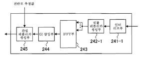
도 5는 레플리카 생성부(232)의 일 구성예를 도시하는 기능 블록도이다. 레플리카 생성부(232)는 인터리브부(241-1), 심볼 레플리카 생성부(242-1), IFFT부(243), GI 삽입부(244), 간섭 레플리카 생성부(245)를 구비한다.5 is a functional block diagram illustrating an example of the configuration of the
인터리브부(241-1)는 신호 검출부(208-1)가 출력하는 복호 후의 부호화 비트의 대수 우도비 LLR을, 송신 장치(100)가 데이터 변조를 실시한 부호화한 데이터 신호와 동일한 정렬 순서로 나란히 재배열한다. 즉, 송신 장치(100)의 인터리브부(112-1)와 같은 인터리브 패턴으로 신호 검출부(208-1)가 출력하는 복호 후의 부호화 비트의 대수 우도비 LLR을 인터리브한다. 즉, 신호 검출부(208-1)가 구비하는 디인터리브부(223-1)와 반대의 재배열을 행한다.The interleave unit 241-1 reconstructs the log-likelihood ratio LLR of the decoded coded bits output by the signal detection unit 208-1 in the same sorting order as the encoded data signal subjected to data modulation by the
심볼 레플리카 생성부(242-1)는 인터리브부(241-1)가 출력하는 부호화 비트의 대수 우도비 LLR을 사용하여 원하는 유저의 신호에 대한 데이터 변조 심볼의 레플리카(변조 심볼 레플리카)를 생성한다. 예를 들어, 심볼 레플리카 생성부(242-1)는 송신 장치(100)의 변조부(113-1)의 변조 방식이 QPSK 변조인 경우, QPSK 변조 심볼을 구성하는 비트 b0, b1의 대수 우도비를 λ(b0), λ(b1)로 했을 때, 하기의 수학식 5로 표현되는 QPSK의 변조 심볼의 레플리카 심볼을 생성한다. 또한, 심볼 레플리카 생성부(242-1)는 16QAM 등의 다른 변조의 경우도, 동일한 원리로 변조 심볼 레플리카를 생성한다.The symbol replica generation unit 242-1 generates a replica (modulation symbol replica) of a data modulation symbol for a desired user's signal using the log likelihood ratio LLR of the encoded bits output from the interleave unit 241-1. For example, when the modulation scheme of the modulator 113-1 of the transmitting

IFFT부(243)는 심볼 레플리카 생성부(242)가 출력하는 변조 심볼 레플리카를 수신한 OFDMA 신호에 있어서 상기 변조 심볼 레플리카에 대응하는 데이터 변조 심볼(유저 1의 데이터 변조 심볼)이 할당되어 있는 리소스 엘리먼트에 해당하는 IFFT 입력 포인트에 맵핑하고, IFFT 처리를 행함으로써, 원하는 유저의 변조 심볼 레플리카(원하는 유저의 변조 심볼 레플리카)를 주파수 영역의 신호로부터 시간 영역의 신호로 변환한다. 또한, 수신한 OFDMA 신호에 있어서 원하지 않는 유저의 데이터 변조 심볼이 배치된 리소스 엘리먼트에 해당하는 IFFT 입력 포인트는 널(null)로 한다(제로를 배치함). 또한, IFFT부(243)는 기지의 신호인 파일럿 심볼이 배치되어 있었던 리소스 엘리먼트에 해당하는 IFFT 입력 포인트에 이 파일럿 심볼을 배치하는 것이 바람직하다.The
예를 들어, 수신한 OFDMA 신호가 도 2의 유저 할당에서 각 유저의 데이터 변조 심볼이 할당되어 있는 경우에, 심볼 레플리카 생성부(242)가 출력하는 변조 심볼 레플리카는 리소스 엘리먼트(K1, L1), (K1=1, …, 12, L1=1, …, 7, 단, 파일럿 심볼을 배치한 리소스 엘리먼트는 제외함)에 해당하는 IFFT 입력 포인트에 할당한다.For example, when the received OFDMA signal is assigned a data modulation symbol of each user in the user assignment of FIG. 2, the modulation symbol replicas output by the symbol
GI 삽입부(244)는 IFFT부(243)가 변환한 시간 영역의 신호에 가드 인터벌(GI)을 부가한다. GI 삽입부(245)가 출력하는 신호 레플리카 s^i(t)는 하기 수학식 6으로 표현할 수 있다.The

단, c^k, 1은 원하는 유저의 변조 심볼 레플리카이다. 또한, 파일럿 심볼 등의 기지의 심볼을 포함해도 된다. 도 2에 도시하는 유저 할당의 경우, 유저 1의 변조 심볼 레플리카 c^K1, L1을, 변조 심볼 cK1, L1이 배치된 리소스 엘리먼트의 서브캐리어 위치에 할당한다. 또한, 파일럿 심볼 c^Kp, Lp을 파일럿 심볼 cKp, Lp가 배치된 리소스 엘리먼트의 서브캐리어 위치에 할당한다. 이에 의해, 송신 신호 레플리카의 생성이 원하는 유저 이외의 신호의 배치에 의존하지 않는다. 따라서, 원하는 유저에 대한 터보 등화 처리의 처리 시간을 크게 연장시키지 않고 간섭을 제거하는 것이 가능하게 된다.However, c ^ k and 1 are modulation symbol replicas of a desired user. Furthermore, known symbols such as pilot symbols may be included. In the user assignment shown in Fig. 2, the modulation symbol replicas c ^ K1 and L1 of
간섭 레플리카 생성부(245)는 GI 삽입부(244)가 출력하는 신호와 전반로 추정값을 사용하여, 수신 장치(200)가 수신하는 OFDMA 신호가 받은 간섭 성분의 간섭 레플리카를 생성한다. 간섭 성분으로서, 심볼간 간섭, 캐리어간 간섭 등이 있고, 각 간섭 성분에 대하여 간섭 레플리카를 생성한다.The
예를 들어, OFDMA 신호가 심볼간 간섭을 받고 있는 경우, 간섭 제거부(204)의 제i회째의 반복 처리에 있어서 GI 삽입부(244)가 출력하는 신호를 s^i(t), 전반로 추정값을 h^(t)라 하면, 간섭 레플리카 생성부(245)가 생성하는 심볼간 간섭 레플리카 r^i(t)(t≤Ts, Ts는 OFDM 심볼 길이)는 하기 수학식 7이 된다. 즉, 간섭 레플리카 r^i는, 제i-1회째의 반복 처리에 있어서 신호 검출부(208-1)가 출력하는 부호화 비트 LLR로부터 생성한 원하는 유저에 대한 송신 신호 레플리카를 사용하여 생성되고, 수신 장치가 수신한 GI를 초과하는 지연 시간을 갖는 각 지연파에 있어서, FFT 처리를 행하는 OFDM 심볼 전의 OFDM 심볼이며, FFT 처리를 행하는 OFDM 심볼 구간에 인입한 성분의 레플리카를 서로 더한 것이다. 상술한 간섭 레플리카를 감산하는 처리를 유저 1이 점유한 리소스 엘리먼트에 있어서 행함으로써 심볼간 간섭을 제거한다. 또한, 원하는 유저에 대한 제어 신호, 파일럿 심볼에의 심볼간 간섭도 마찬가지로 제거하는 것이 가능하다.For example, when the OFDMA signal is subjected to intersymbol interference, the signal output from the

단, 첫회 처리의 경우(i=0), r^0(t)=0이며, h^d는 전반로 추정값의 임펄스 응답이며, 제d 패스의 복소 진폭, t는 시간, τd는 제d 패스(제d 지연파)의 제1 패스(선행파)가 도달한 시점(FFT 처리의 동기 포인트)으로부터의 지연 시간, Tgi는 삽입되어 있는 가드 인터벌 길이를 나타낸다. 또한, d는 τd>Tgi를 만족시키는 경우로 한다.However, for the first process (i = 0), r ^ 0 (t) = 0, h ^ d is the impulse response of the propagation path estimate, the complex amplitude of the d-th pass, t is the time, τd is the d-th pass The delay time from the time point (synchronization point of the FFT process) when the first pass (predecessor wave) of the (d delayed wave) arrives, Tgi, represents the guard interval length inserted. D is a case where τd> Tgi is satisfied.
또한, 상술에서는, 시간 영역의 간섭 레플리카를 수신 신호로부터 감산함으로써 심볼간 간섭의 제거를 행한 경우를 나타내고 있지만, 이 경우에 한정하는 것은 아니다. 예를 들어, 시간 영역의 간섭 레플리카 외에, 주파수 영역의 간섭 레플리카를 사용하여 심볼간 간섭의 제거를 행해도 된다.In addition, although the case where inter-symbol interference is removed by subtracting the interference replica of a time domain from a received signal is shown, it is not limited to this case. For example, in addition to the interference replica in the time domain, the inter-symbol interference may be removed using the interference replica in the frequency domain.
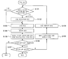
도 6은 수신 장치(200)의 동작을 설명하는 흐름도이다. 수신 장치(200)는 송신 장치(100)로부터 송신된 OFDMA 신호를 수신하면, 간섭 제거부(204)에 있어서의 반복 간섭 제거 처리에 있어서, 그의 반복 횟수를 판정하고(S101), 첫회 처리(i=0)인 경우에는, 수신한 OFDMA 신호를 그대로 출력한다. 이 신호는 GI 제거부(205)에 있어서의 처리 후, FFT부(206)에 입력된다. 한편, 반복 처리(i>0)일 경우, 제i-1회째의 반복 처리에 있어서의 원하는 유저에 대한 복호 처리에 의해 산출한 부호화 비트 LLR로부터 생성한 간섭 레플리카를 사용하여 원하는 유저의 신호에 대한 간섭 제거를 행한다(S102).6 is a flowchart for explaining an operation of the receiving
이어서, S101 및 S102의 처리를 행한 신호에 대하여 FFT부(206)에 있어서 FFT 처리를 행하고(S103), 주파수 영역으로 변환된 신호에 대하여 전반로 보상부(207)에 있어서 전반로 왜곡의 보상(등화 처리)을 행한다(S104). 등화 처리를 행한 주파수 영역의 신호(등화후 신호)로부터 원하는 유저에 대한 등화후 신호를 추출하고, 복조 처리, 복호 처리를 행한 후(S105), 간섭 제거 처리에 있어서 소정의 반복 횟수가 종료된 경우(S106의 "예"), 원하는 복호 처리 결과의 경판정한 결과를 MAC부 등에 전달하고, 처리를 종료하고 다음 데이터를 수신 대기한다. 한편, 소정의 반복 횟수가 종료되지 않은 경우(S106의 "아니오"), 원하는 유저의 데이터 신호의 오류의 유무를 판정하고(S107), 오류가 없는 경우, 원하는 복호 처리 결과의 경판정한 결과를 MAC부 등에 전달하고, 처리를 종료하고 다음 데이터를 수신 대기한다. 한편, 오류가 있는 경우, 복호부(223-1)가 출력하는 부호화 비트 LLR을 사용하여 원하는 유저에 대한 변조 심볼 레플리카를 생성한다(S108). 그리고, 상기 원하는 유저에 대한 변조 심볼 레플리카를 사용하여 간섭 레플리카를 생성하고(S109), 간섭 제거부(204)에 입력하고, 다시 간섭 제거 처리를 행한다(스텝 S101에 복귀된다). 즉, 미리 설정한 횟수만큼 처리가 반복되든, 또는, 데이터 신호의 오류가 없다고 판정되든, 어느 하나의 조건이 만족될때까지 처리를 반복한다.Subsequently, the FFT process is performed by the
이상과 같이, 본 실시 형태에서는, 송신 장치(100)가 OFDMA 신호를 송신하고, 수신 장치(200)가 가드 인터벌을 초과하는 길이 지연을 갖고 OFDMA 신호를 수신한 경우, 일부의 복호 결과로부터 생성한 간섭 레플리카를 사용하여, 반복 간섭 제거 처리를 행한다.As described above, in the present embodiment, when the transmitting
이에 의해, OFDMA 신호의 리소스 엘리먼트에 할당되어 있는 원하지 않는 유저의 리소스 엘리먼트의 점유 영역에 영향받지 않고, 원하는 유저의 터보 등화 처리(반복 처리)를 행할 수 있다. 따라서, 원하는 유저와 원하지 않는 유저의 리소스 엘리먼트의 점유 영역의 차이에 의한 터보 등화의 처리 지연을 억제할 수 있다는 이점이 있다.Thereby, the turbo equalization process (repeating process) of a desired user can be performed, without being influenced by the occupation area of the resource element of the unwanted user allocated to the resource element of an OFDMA signal. Therefore, there is an advantage that the processing delay of turbo equalization due to the difference in the occupied area of the resource element of the desired user and the unwanted user can be suppressed.
또한, 유저마다 정보 데이터가 부호화되어, 원하지 않는 유저가 점유하는 OFDM 심볼수가, 원하는 유저가 점유하는 OFDM 심볼수보다도 많은 경우에 있어서도, 원하지 않는 유저의 복호 처리 시간에 구속되는 경우가 없고, 원하는 유저에 대한 터보 등화 처리를 행할 수 있다. 즉, 수신 장치는, 자(自) 유저의 신호에 대한 복호 처리가 종료되었음에도 불구하고, 타 유저의 신호의 복호 처리가 끝나지 않았다는 이유로, 심볼간 간섭 레플리카 생성 등의 후속하는 처리를 행할 수 없다는 문제의 발생을 억제할 수 있다. 그 결과, 원하는 유저의 신호에 대한 최종적인 정보 데이터를 취득하기 위하여 필요로 하는 처리 시간이 연장되는 것을 억제하고, 소비 전력을 증가, 수신기의 효율을 악화시키는 것을 억제할 수 있다.In addition, even if the information data is encoded for each user and the number of OFDM symbols occupied by an unwanted user is larger than the number of OFDM symbols occupied by a desired user, the user is not limited to the decoding processing time of an unwanted user. Turbo equalization processing can be performed. That is, the receiving device cannot perform subsequent processing such as inter-symbol interference replica generation, even though the decoding processing of the own user's signal is not finished, because the decoding processing of the other user's signal is not finished. Can be suppressed. As a result, it is possible to suppress the prolongation of the processing time required for acquiring the final information data on the signal of the desired user, increase the power consumption, and suppress the deterioration of the efficiency of the receiver.
또한, 복수의 유저의 부호화 블록의 비트수가 상이하게 됨으로써 터보 등화 처리 시간을 연장시키지 않고, 심볼간 간섭, 서브캐리어간 간섭을 제거하여, 전송 특성을 개선할 수 있다. 특히, 원하지 않는 유저의 부호화 블록수가, 원하는 유저의 부호화 블록의 비트수보다도 많은 경우에 있어서도, 원하는 유저의 부호화 블록의 비트수에 기초하여 터보 등화 처리를 행할 수 있다.In addition, since the number of bits of the coding blocks of a plurality of users is different, the inter-symbol interference and the inter-carrier interference can be eliminated without extending the turbo equalization processing time, thereby improving the transmission characteristics. In particular, even when the number of coding blocks of the unwanted user is larger than the number of bits of the coding block of the desired user, turbo equalization processing can be performed based on the number of bits of the coding block of the desired user.
또한, 반복 처리에 부여된 시간이 일정하게 정해져 있는 경우, 타 유저의 신호의 복호 처리 시간의 영향에 의해 자 유저의 신호에 대한 터보 등화의 반복 횟수가 감소하는 것을 방지할 수 있어, 오류율 특성의 열화를 억제할 수 있다. 또한, 본 실시 형태에서는, 심볼간 간섭을 제거하는 경우에서 설명했지만, 이것에 한정하는 것은 아니다. 예를 들어, 서브캐리어간 간섭에 있어서도, 원하는 유저의 신호에 대한 데이터 변조 레플리카를 사용하여 서브캐리어간 간섭의 간섭 레플리카를 생성하고, 수신 신호로부터 제거할 수 있다. 또한, 본 실시 형태에서는, 동일한 송신 프레임에서, 복수의 유저가 할당되어 있는 경우로 설명했지만, 유저가 복수의 송신 프레임에 걸쳐서 할당되어 있는 경우에 있어서도 적용할 수 있다.In addition, when the time given to the repetition process is fixed, the number of repetitions of turbo equalization with respect to the signal of the self-user can be prevented from being reduced by the influence of the decoding processing time of the signal of the other user, thereby reducing the error rate characteristics. Deterioration can be suppressed. In addition, although this embodiment demonstrated the case where the interference between symbols is removed, it is not limited to this. For example, even in the inter-carrier interference, a replica of the interference between the sub-carriers can be generated and removed from the received signal using the data modulation replica for the desired user's signal. In addition, in this embodiment, although demonstrated as the case where the some user is assigned in the same transmission frame, it is applicable also when the user is assigned over the some transmission frame.
(제2 실시 형태)(Second Embodiment)
본 발명의 제2 실시 형태에 의한 통신 시스템은, 송신 장치(100)와 송신 장치(100)가 송신한 OFDMA 신호를 수신하는 수신 장치(400)로 구성된다. 이하에서는, 수신 장치(400)에 대하여 설명한다.The communication system according to the second embodiment of the present invention is composed of a
도 7은 본 발명의 제2 실시 형태에 따른 수신 장치(400)의 일 구성예를 도시하는 기능 블록도이다. 수신 장치(400)는 송신 장치(100)가 송신하는 신호를 수신하는 유저 1의 이동 단말기에 탑재되어 있는 것으로 하여 설명한다. 또한, 유저 n(n=1, 2, ···, N)의 이동 단말기에 탑재되는 수신 장치도, 적어도 동일한 기능을 갖는 것이 가능하다.7 is a functional block diagram showing an example of the configuration of a receiving
수신 장치(400)는 수신부(202), 수신 신호 기억부(203), 간섭 제거부(404), GI 제거부(205), FFT부(206), 전반로 보상부(207), 서브캐리어 디맵핑부(210), 신호 검출부(208-1), 전반로 추정부(209), 복조부(221-2 내지 221-N)를 구비하고, 수신부(202)에 안테나부(201)가 접속되어 있다. 또한, 상기 수신 장치(400)의 일부 또는 전부를 칩화하여 집적 회로가 되는 경우, 각 기능 블록에 대하여 제어를 행하는 칩 제어 회로(211)를 갖는다.The
제1 실시 형태의 수신 장치(200)와 동등한 기능을 갖는 구성 요소에는 동일한 부호를 부여하고 있다. 수신 장치(400)는 수신 장치(200)에 대하여 간섭 제거부(204)가 간섭 제거부(404)로 대체되고, 복조부(221-2) 내지 복조부(221-N)가 추가된 점에서 상이하다. 이하에서는, 주로, 수신 장치(200)와 상이한 기능을 갖는 구성 요소에 대하여 설명한다.The same code | symbol is attached | subjected to the component which has a function equivalent to the receiving
간섭 제거부(404)는 반복 처리(i>0)에 있어서는, 신호 검출부(208-1), 복조부(221-1) 내지 복조부(221-N) 및 전반로 추정부(209)로부터 출력되는 신호를 사용하여 간섭 제거 처리를 행한다.The
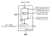
도 8은 간섭 제거부(404)의 일 구성예를 도시하는 기능 블록도이다. 간섭 제거부(404)는 감산부(231), 레플리카 생성부(432)를 구비한다. 레플리카 생성부(432)는 복호부(223-1)가 출력한 유저 1의 복호 후의 부호화 비트 LLR, 복조부(221-2) 내지 복조부(221-N)의 복조 후의 부호화 비트 LLR을 사용하여 간섭 레플리카를 생성한다. 감산부(231)는 이 간섭 레플리카를 수신부(202) 또는 수신 신호 기억부(203)로부터 입력되는 신호로부터 감산한다.8 is a functional block diagram illustrating an example of the configuration of the
도 9는 레플리카 생성부(432)의 일 구성예를 도시하는 기능 블록도이다. 레플리카 생성부(432)는 인터리브부(241-1), 심볼 레플리카 생성부(242-1), 심볼 레플리카 생성부(242-2 내지 242-N), IFFT부(243), GI 삽입부(244), 간섭 레플리카 생성부(245)를 구비한다.9 is a functional block diagram illustrating an example of the configuration of the
심볼 레플리카 생성부(242-1)는 복호부(223-1)가 출력하는 복호 후의 부호화 비트 LLR을 인터리브부(241-1)로 인터리브한 부호화 비트 LLR을 사용하여, 유저 1의 신호에 대한 데이터 변조 심볼의 레플리카(변조 심볼 레플리카)를 생성한다.The symbol replica generator 242-1 uses the encoded bit LLR obtained by interleaving the encoded bit LLR decoded by the decoder 223-1 into the interleave unit 241-1. Generate a replica of the modulation symbol (modulation symbol replica).
서브캐리어 디맵핑부(210)는 전반로 보상부(207)가 출력하는 신호에 대하여 디맵핑 처리를 행한다. 구체적으로는, 전반로 보상부(207)가 출력하는 신호 중, 원하는 유저(유저 1)가 맵핑되어 있는 서브캐리어의 신호를 추출하고, 신호 검출부(208-1)에 입력한다. 또한, 원하지 않는 유저가 맵핑되어 있는 서브캐리어의 신호를 추출하고, 복조부(221-2) 내지 복조부(221-N)에 입력한다.The
심볼 레플리카 생성부(242-n)(n=2, …, N)는 복조부(221-n)(n=2, ···, N)가 출력하는 유저 n의 복조 후의 부호화 비트 LLR을 사용하여, 유저 n의 신호에 대한 변조 심볼의 레플리카(변조 심볼 레플리카)를 생성한다.The symbol replica generator 242-n (n = 2, ..., N) uses the coded bit LLR after demodulation of user n outputted by the demodulator 221-n (n = 2, ..., N). Thus, a replica of the modulation symbol (modulation symbol replica) for the signal of user n is generated.
IFFT부(243)는 심볼 레플리카 생성부(242-n)(n=1, 2, …, N)가 출력하는 변조 심볼 레플리카를 수신한 OFDMA 신호에 있어서 변조 심볼 레플리카에 대응하는 데이터 변조 심볼이 할당되어 있는 리소스 엘리먼트에 해당하는 IFFT 입력 포인트에 맵핑하고, IFFT 처리를 행한다. GI 삽입부(244)에 있어서, IFFT 처리 후의 신호에 GI를 부가한 신호 레플리카는 상기 수학식 6이 된다. 단, c^k, l은, 상기 심볼 레플리카 생성부(242-1 내지 242-N)에서 생성된 변조 심볼 레플리카이다.The
즉, 레플리카 생성부(432)는 원하는 유저의 데이터 변조 심볼에 대한 변조 심볼 레플리카만 복호 후의 부호화 비트 LLR로부터 생성하고, 원하지 않는 유저의 데이터 변조 심볼에 대한 변조 심볼 레플리카는 복조 후의 부호화 비트 LLR로부터 생성한다. 그리고, 이것들 수신한 전체 유저의 데이터 변조 심볼에 대한 변조 심볼 레플리카를 사용하여 간섭 레플리카를 생성한다. 수신 장치(400)가 도 2에 기재된 복수의 유저가 할당되어 있는 OFDMA 신호를 수신한 경우, 제1 OFDM 심볼 내지 제7 OFDM 심볼에 대하여 터보 등화 처리를 적용하는 경우에는, 유저 1을 점유하고 있는 리소스 엘리먼트에는 복호 후의 부호화 비트 LLR로부터 생성한 변조 심볼 레플리카를 배치하고, 유저 3이 점유하고 있는 리소스 엘리먼트에는 복조 후의 부호화 비트 LLR로부터 생성한 변조 심볼 레플리카를 배치하고, 송신 신호 레플리카를 생성한다.That is, the
또한, 터보 등화 처리를 적용하는 OFDM 심볼이 상기 OFDM 심볼의 뒤의 OFDM 심볼로부터 간섭을 받는 경우에는, 뒤의 OFDM 심볼에 배치한 데이터 변조 심볼에 대한 변조 심볼 레플리카를 사용할 수 있다. 예를 들어, 제7 OFDM 심볼에 대하여 터보 등화를 적용하는 경우, 제8 OFDM 심볼에 배치한 유저 2의 데이터 변조 심볼에 대한 복조 후의 변조 심볼 레플리카를 사용하여 송신 신호 레플리카를 생성할 수도 있다. 도 11은 복수 유저의 데이터 변조 심볼과 파일럿 심볼이 리소스 엘리먼트에 맵핑된 다른 예를 도시하는 도면이다. 수신 장치(400)가 도 11에 기재된 복수의 유저가 할당되어 있는 OFDMA 신호를 수신하고, 유저 1이 점유하는 제1 OFDM 심볼 내지 제7 OFDM 심볼에 대하여 터보 등화 처리를 행하는 경우에는, 유저 1을 점유하고 있는 리소스 엘리먼트에는 복호 후의 부호화 비트 LLR로부터 생성한 변조 심볼 레플리카를 배치하고, 유저 3이 점유하고 있는 리소스 엘리먼트에는 복조 후의 부호화 비트 LLR로부터 생성한 변조 심볼 레플리카를 배치하고, 송신 신호 레플리카를 생성한다. 추가로, 제7 OFDM 심볼에 대하여 터보 등화를 적용하는 경우, 또한 제8 OFDM 심볼에 배치한 유저 2 및 유저 4의 데이터 변조 심볼에 대한 복조 후의 변조 심볼 레플리카를 사용하여 송신 신호 레플리카를 생성할 수도 있다.Further, when an OFDM symbol to which turbo equalization processing is applied interferes with the OFDM symbol after the OFDM symbol, a modulation symbol replica for the data modulation symbol arranged in the later OFDM symbol can be used. For example, when turbo equalization is applied to the seventh OFDM symbol, a transmission signal replica may be generated using a modulation symbol replica after demodulation on a data modulation symbol of
도 12는 복수 유저의 데이터 변조 심볼과 파일럿 심볼이 리소스 엘리먼트에 맵핑된 다른 예를 도시하는 도면이다. 수신 장치(400)가 도 12에 기재된 복수의 유저가 할당되어 있는 OFDMA 신호를 수신하고, 유저 1이 점유하는 제1 OFDM 심볼 내지 제11의 OFDM 심볼에 대하여 터보 등화 처리를 행하는 경우에는, 유저 1을 점유하고 있는 리소스 엘리먼트에는 복호 후의 부호화 비트 LLR로부터 생성한 변조 심볼 레플리카를 배치하고, 유저 3, 유저 4이 점유하고 있는 리소스 엘리먼트에는 복조 후의 부호화 비트 LLR로부터 생성한 변조 심볼 레플리카를 배치하고, 송신 신호 레플리카를 생성한다. 추가로, 제11의 OFDM 심볼에 대하여 터보 등화를 적용하는 경우, 또한 제12의 OFDM 심볼에 배치한 유저 2의 데이터 변조 심볼에 대한 복조 후의 변조 심볼 레플리카를 사용하여 송신 신호 레플리카를 생성할 수도 있다.12 is a diagram illustrating another example in which data modulation symbols and pilot symbols of a plurality of users are mapped to resource elements. When the
이에 의해, 원하는 유저에 대한 터보 등화 처리의 처리 시간을 크게 연장시키지 않고 원하지 않는 유저의 변조 심볼 레플리카의 생성을 하는 것이 가능하게 된다.This makes it possible to generate modulation symbol replicas of unwanted users without significantly extending the processing time of turbo equalization processing for the desired users.
복조부(221-2 내지 221-N)는 전반로 보상부(207)가 출력하는 등화후 신호 중, 원하지 않는 유저를 수신처로 하는 데이터 변조 심볼이 맵핑된 리소스 엘리먼트의 등화후 신호를 추출하고, 상기 추출한 등화후 신호에 대하여 복조 처리를 행하고, 연판정값(복조 후의 부호화 비트 LLR)을 간섭 제거부(404)에 입력한다.The demodulators 221-2 to 221-N extract the post-equalization signal of the resource element to which the data modulation symbol to which an undesired user is received from among the post-equalization signals output from the propagation path compensator 207, A demodulation process is performed on the extracted equalized signal, and a soft decision value (coded bit LLR after demodulation) is input to the
도 10은 수신 장치(200)의 동작을 설명하는 흐름도이다. 수신 장치(200)는 송신 장치(100)로부터 송신된 OFDMA 신호를 수신하면, 간섭 제거부(404)에 있어서의 반복 간섭 제거 처리에 있어서, 그의 반복 횟수를 판정하고(S201), 첫회 처리(i=0)인 경우에는, 수신한 OFDMA 신호를 그대로 출력한다. 이 신호는 GI 제거부(205)에 있어서의 처리 후, FFT부(206)에 입력된다. 한편, 반복 처리(i>0)일 경우, 제i-1회째의 반복 처리에 있어서의 원하는 유저에 대한 복호 처리에 의해 산출한 부호화 비트 LLR와 원하지 않는 유저에 대한 복조 처리에 의해 산출한 부호화 비트 LLR로부터 생성한 간섭 레플리카를 사용하여 간섭 제거를 행한다(S202).10 is a flowchart for explaining the operation of the
이어서, S201 및 S202의 처리를 행한 신호에 대하여 FFT부(206)에 있어서 FFT 처리를 행하고(S203), 주파수 영역으로 변환된 신호에 대하여 전반로 보상부(207)에 있어서 전반로 왜곡의 보상(등화 처리)을 행한다(S204). 등화 처리를 행한 주파수 영역의 신호(등화후 신호)로부터 원하는 유저에 대한 등화후 신호를 추출하고, 복조 처리, 복호 처리를 행한 후(S205), 간섭 제거 처리에 있어서 소정의 반복 횟수가 종료된 경우(S206의 "예"), 원하는 복호 처리 결과의 경판정한 결과를 MAC부 등에 전달하고, 처리를 종료하고 다음 데이터를 수신 대기한다. 한편, 소정의 반복 횟수가 종료되지 않은 경우(S206의 "아니오"), 원하는 유저의 데이터 신호의 오류의 유무를 판정하고(S207), 오류가 없는 경우, 원하는 복호 처리 결과의 경판정한 결과를 MAC부 등에 전달하고, 처리를 종료하고 다음 데이터를 수신 대기한다. 한편, 오류가 있는 경우, 변조 심볼 레플리카를 생성한다. 그 경우, 레플리카 생성이 원하는 유저에 대한 데이터 변조 심볼에 대한 것인가 아닌가를 판단한다(S208). 원하는 유저에 대한 변조 심볼 레플리카의 경우(S208의 "예"), 복호부(223-1)가 출력하는 복호 후의 부호화 비트 LLR로부터 변조 심볼 레플리카를 생성한다(S209). 원하지 않는 유저에 대한 변조 심볼 레플리카의 경우(S208의 "아니오"), 복조부(221-2) 내지 복조부(221-N)가 출력하는 복조 후의 부호화 비트 LLR로부터 변조 심볼 레플리카를 생성한다(S210). 그리고, S209 및 S210에서 생성한 각 유저에 대한 변조 심볼 레플리카를 사용하여 간섭 레플리카를 생성하고(S211), 간섭 제거부(204)에 입력하고, 다시 간섭 제거 처리를 행한다.Subsequently, the
즉, 미리 설정한 횟수만큼 처리가 반복되든, 또는, 데이터 신호의 오류가 없다고 판정되든, 어느 하나의 조건이 만족될때까지 처리를 반복한다. 또한, 상기 S210에 있어서 생성하는 변조 심볼 레플리카는 S209로 변조 심볼 레플리카를 생성한 변조 심볼 이외이며, 그의 일부 또는 전부 중의 어느 것이어도 된다.In other words, whether the process is repeated a predetermined number of times or it is determined that there is no error in the data signal, the process is repeated until either condition is satisfied. In addition, the modulation symbol replica produced in said S210 is other than the modulation symbol which produced the modulation symbol replica in S209, and some or all of them may be sufficient as it.
이상과 같이, 본 실시 형태에서는, 송신 장치(100)가 OFDMA 신호를 송신하고, 수신 장치(400)가 OFDMA 신호를 가드 인터벌을 초과하는 길이 지연을 갖고 수신한 경우, 원하는 유저에 대해서는 복호 결과로부터 변조 심볼 레플리카를 생성하고, 원하지 않는 유저에 대해서는 복조 결과로부터 변조 심볼 레플리카를 생성한다. 그리고, 상기 원하는 유저 및 원하지 않는 유저에 대한 변조 심볼 레플리카로부터 생성한 간섭 레플리카를 사용하여 반복 간섭 제거 처리를 행한다.As described above, in the present embodiment, when the transmitting
이에 의해, OFDMA 신호의 리소스 엘리먼트에 할당되어 있는 원하지 않는 유저의 리소스 엘리먼트의 점유 영역에 영향받지 않고, 원하는 유저의 터보 등화 처리(반복 처리)를 행할 수 있다. 따라서, 원하는 유저와 원하지 않는 유저의 리소스 엘리먼트의 점유 영역의 차이에 의한 터보 등화의 처리 지연을 억제할 수 있다는 이점이 있다. 또한, 간섭 레플리카 생성에 있어서, 원하지 않는 유저에 대해서도 변조 처리 후의 부호화 비트 LLR을 사용하므로, 원하지 않는 유저의 신호 성분이 원하는 유저의 신호 성분에 부여하는 간섭도 억제할 수 있고, 특성 열화를 억제할 수 있다는 이점이 있다.Thereby, the turbo equalization process (repeating process) of a desired user can be performed, without being influenced by the occupation area of the resource element of the unwanted user allocated to the resource element of an OFDMA signal. Therefore, there is an advantage that the processing delay of turbo equalization due to the difference in the occupied area of the resource element of the desired user and the unwanted user can be suppressed. In addition, in the generation of the interference replica, since the coded bit LLR after the modulation process is also used for the unwanted user, the interference that the signal component of the unwanted user imparts to the signal component of the desired user can also be suppressed, and the deterioration of characteristics can be suppressed. There is an advantage that it can.
또한, 상술한 제1 실시 형태 및 제2 실시 형태에서는, OFDM의 서브캐리어에 복수의 유저의 신호를 할당하는 OFDMA에 본 발명을 적용한 경우로 설명했지만, 이에 한정하지 않고, MC-CDMA(Multi Carrier - Code Division Multiple Access), SC-FDMA(Single Carrier - Frequency Division Multiple Access), DFT-S-OFDMA(Discrete Fourier Transform - Spread - OFDMA) 등의 유저가 주파수 분할 다중되어 있는 신호를 송신하는 통신 시스템에 적용할 수 있다. 또한, 상술한 실시 형태에서는, OFDMA 및 상기에 예시열거한 전송 방식을 멀티 캐리어 변조라고 칭한다.In the first and second embodiments described above, the present invention is applied to OFDMA in which signals of a plurality of users are assigned to OFDM subcarriers. However, the present invention is not limited thereto, and MC-CDMA (Multi Carrier) is not limited thereto. -A communication system for transmitting signals in which users are frequency division multiplexed, such as Code Division Multiple Access (SC-FDMA), Single Carrier-Frequency Division Multiple Access (SC-FDMA), and Discrete Fourier Transform-Spread-OFDMA (DFT-S-OFDMA). Applicable In addition, in the above-described embodiment, the OFDMA and the transmission methods exemplified above are referred to as multicarrier modulation.
(제3 실시 형태)(Third embodiment)
본 발명의 실시 형태에서는, 송신 장치가 직교하는 멀티 캐리어에 있어서 단수의 유저가 점유하는 OFDM의 신호를 송신하는 경우를 예로 하여 설명한다.In the embodiment of the present invention, a case in which the transmitting device transmits an OFDM signal occupied by a single user in a multicarrier orthogonal will be described as an example.
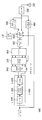
도 13은 본 발명의 제3 실시 형태에 따른 송신 장치(500)의 일 구성예를 도시하는 기능 블록도이다. 송신 장치(500)는 심볼 생성부(502-1 내지 502-N), IFFT(역고속 푸리에 변환)부(103), GI 삽입부(104), 송신부(105) 및 파일럿 생성부(106)를 포함하여 구성되고, 송신부(105)에 안테나부(101)가 접속되어 있다. 또한, N은 유저 1의 정보 비트를 부호화하는 부호화 블록수이다.13 is a functional block diagram illustrating an example of a configuration of a
송신 장치(500)는 송신 장치(100)로부터 심볼 생성부(102-n)(n=1, 2, …, N) 대신에, 심볼 생성부(502-n)를 배치하고 있다. 심볼 생성부(502-n)는 심볼 생성부(102-n)로부터 동일 유저의 정보 비트가 입력되는 것이 상이하다.The
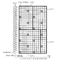
도 14는 심볼 생성부(502-n)(n=1, 2, 3)로부터 입력되는 유저 1의 데이터 변조 심볼과 파일럿 심볼을 IFFT부(103)의 입력 포인트에 맵핑한 예를 도시하는 도면이다.FIG. 14 is a diagram showing an example of mapping data modulation symbols and pilot symbols of
사선의 리소스 엘리먼트에는 파일럿 심볼을 배치하고 있다. 부호부(111-1)에 의해 부호화된 부호화 비트가 맵핑된 데이터 변조 심볼은 리소스 엘리먼트(K1, L1), (K1=1, …, 12, L1=1, …, 7, 단, 파일럿 심볼을 배치한 리소스 엘리먼트는 제외함)에 배치된다. 부호부(111-2)에 의해 부호화된 부호화 비트가 맵핑된 데이터 변조 심볼은, 리소스 엘리먼트(K2, L2), (K2=1, …, 12, L2=8, …, 14, 단, 파일럿 심볼을 배치한 리소스 엘리먼트는 제외함)에 배치된다. 부호부(111-3)에 의해 부호화된 부호화 비트가 맵핑된 데이터 변조 심볼은, 리소스 엘리먼트(K3, L3), (K3=13, …, 24, L3=1, …, 14, 단, 파일럿 심볼을 배치한 리소스 엘리먼트는 제외함)에 배치된다.Pilot symbols are arranged in the diagonal resource elements. The data modulation symbols to which encoded bits encoded by the coder 111-1 are mapped include resource elements K1 and L1, (K1 = 1,..., 12, L1 = 1,. Excluded resource elements are placed). The data modulation symbols to which encoded bits encoded by the coder 111-2 are mapped include resource elements K2 and L2, (K2 = 1,..., 12, L2 = 8, ..., 14, but pilot symbols. Except for resource elements that have deployed). The data modulation symbols to which encoded bits encoded by the coder 111-3 are mapped include resource elements K3 and L3, (K3 = 13,..., 24, L3 = 1, ..., 14, where pilot symbols are used. Except for resource elements that have deployed).
도 15는 본 발명의 제3 실시 형태에 따른 수신 장치(600)의 일 구성예를 도시하는 기능 블록도이다. 수신 장치(600)는 송신 장치(500)가 송신하는 신호를 수신하는 이동 단말기에 탑재되어 있는 것으로 하여 설명한다.15 is a functional block diagram illustrating an example of a configuration of a receiving
수신 장치(600)는 수신부(202), 수신 신호 기억부(203), 간섭 제거부(604), GI 제거부(205), FFT부(206), 전반로 보상부(207), 서브캐리어 디맵핑부(210), 신호 검출부(208-1 내지 208-N), 전반로 추정부(209)를 구비하고, 수신부(202)에 안테나부(201)가 접속되어 있다. 또한, 상기 수신 장치(600)의 일부 또는 전부를 칩화하여 집적 회로가 되는 경우, 각 기능 블록에 대하여 제어를 행하는 칩 제어 회로(211)를 갖는다.The
제1 실시 형태의 수신 장치(200)와 동등한 기능을 갖는 구성 요소에는 동일한 부호를 부여하고 있다. 수신 장치(600)는 수신 장치(200)에 대하여 간섭 제거부(204)가 간섭 제거부(604)로 대체되고, 신호 검출부(221-2) 내지 신호 검출부(221-N)가 추가된 점에서 상이하다. 이하에서는, 주로, 수신 장치(200)와 상이한 기능을 갖는 구성 요소에 대하여 설명한다.The same code | symbol is attached | subjected to the component which has a function equivalent to the receiving
간섭 제거부(604)는 반복 처리(i>0)에 있어서는, 신호 검출부(208-1) 내지 신호 검출부(208-N) 중 적어도 1개로부터 출력되는 신호 및 전반로 추정부(209)로부터 출력되는 신호를 사용하여 간섭 제거 처리를 행한다.The
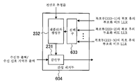
도 16은 간섭 제거부(604)의 일 구성예를 도시하는 기능 블록도이다. 간섭 제거부(604)는 감산부(231), 레플리카 생성부(232), 선택부(633)를 구비한다. 선택부(633)는 복호부(223-1) 내지 복호부(223-N)가 출력하는 복호 후의 부호화 비트 LLR가 입력되고, 원하는 부호화 블록에 대한 복호 후의 부호화 비트 LLR을 선택하고, 레플리카 생성부(232)에 출력한다. 예를 들어, 터보 등화 처리를 적용하여 부호부(111-1)로 부호화한 신호의 정보 데이터를 산출하고자 하는 경우, 도 10-4의 리소스 엘리먼트(K1, L1)에 배치된 데이터 변조 심볼을 복호하는 복호부(223-1)가 출력하는 복호 후의 부호화 비트 LLR만을 선택한다. 레플리카 생성부(232)는 선택부(633)가 출력하는 복호 후의 부호화 비트 LLR만을 사용하여 간섭 레플리카를 생성한다. 레플리카 생성부(232)의 기능은 도 5에 준한다. 감산부(231)는 이 간섭 레플리카를 수신부(202) 또는 수신 신호 기억부(203)로부터 입력되는 신호로부터 감산한다.16 is a functional block diagram illustrating an example of the configuration of the
서브캐리어 디맵핑부(210)는 전반로 보상부(207)가 출력하는 신호에 대하여 디맵핑 처리를 행한다. 구체적으로는, 전반로 보상부(207)가 출력하는 신호 중, 부호화 블록마다, 해당하는 신호 검출부(208-1) 내지 신호 검출부(208-N)에 입력한다. 즉, 부호부(111-n)(n=1, 2, …, N)에 의해 부호화되어 있는 신호는, 신호 검출부(208-n)에 의해 복호 처리를 행한다.The
신호 검출부(208-n)는 각각에서 산출한 복호 후의 부호화 비트 LLR을 간섭 제거부(604)에 출력한다.The signal detectors 208-n output the decoded encoded bits LLRs calculated by the respective signals to the
이에 의해, 송신 신호 레플리카의 생성이 원하지 않는 부호화 블록의 신호의 배치에 의존하지 않는다. 따라서, 원하는 부호화 블록의 신호에 대한 터보 등화 처리의 처리 시간을 크게 연장시키지 않고, 간섭을 제거하는 것이 가능하게 된다.As a result, the generation of the transmission signal replica does not depend on the arrangement of the signals of the unwanted coding block. Therefore, it is possible to eliminate the interference without greatly extending the processing time of the turbo equalization process for the signal of the desired coding block.
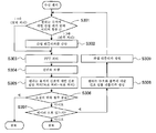
도 17은 수신 장치(600)의 동작을 설명하는 흐름도이다. 수신 장치(600)는 송신 장치(400)로부터 송신된 OFDM 신호를 수신하면, 간섭 제거부(604)에 있어서의 반복 간섭 제거 처리에 있어서, 그의 반복 횟수를 판정하고(S301), 첫회 처리(i=0)인 경우에는, 수신한 OFDM 신호를 그대로 출력한다. 이 신호는 GI 제거부(205)에 있어서의 처리 후, FFT부(206)에 입력된다. 한편, 반복 처리(i>0)일 경우, 제i-1회째의 반복 처리에 있어서의 원하는 부호화 블록에 대한 복호 처리에 의해 산출한 부호화 비트 LLR로부터 생성한 간섭 레플리카를 사용하여 원하는 유저의 신호에 대한 간섭 제거를 행한다(S302).17 is a flowchart illustrating the operation of the receiving
이어서, S301 및 S302의 처리를 행한 신호에 대하여 FFT부(206)에 있어서 FFT 처리를 행하고(S303), 주파수 영역으로 변환된 신호에 대하여 전반로 보상부(207)에 있어서 전반로 왜곡의 보상(등화 처리)을 행한다(S304). 등화 처리를 행한 주파수 영역의 신호(등화후 신호)로부터 원하는 유저에 대한 등화후 신호를 추출하고, 복조 처리, 복호 처리를 행한 후(S305), 간섭 제거 처리에 있어서 소정의 반복 횟수가 종료된 경우(S306의 "예"), 원하는 복호 처리 결과의 경판정한 결과를 MAC부 등에 전달하고, 처리를 종료하고 다음 데이터를 수신 대기한다. 한편, 소정의 반복 횟수가 종료되지 않은 경우(S306의 "아니오"), 원하는 유저의 데이터 신호의 오류의 유무를 판정하고(S307), 오류가 없는 경우, 원하는 복호 처리 결과의 경판정한 결과를 MAC부 등에 전달하고, 처리를 종료하고 다음 데이터를 수신 대기한다. 한편, 오류가 있는 경우, 복호부(223-1) 내지 복호부(223-N)가 출력하는 부호화 비트 LLR 중, 원하는 부호화 블록에 대한 부호화 비트 LLR을 사용하여, 원하는 부호화 블록에 대한 변조 심볼 레플리카를 생성한다(S308). 그리고, 상기 원하는 부호화 블록에 대한 변조 심볼 레플리카를 사용하여 간섭 레플리카를 생성하고(S309), 간섭 제거부(604)에 입력하고, 다시 간섭 제거 처리를 행한다(스텝 S301에 복귀된다). 즉, 미리 설정한 횟수만큼 처리가 반복되든, 또는, 데이터 신호의 오류가 없다고 판정되든, 어느 하나의 조건이 만족될때까지 처리를 반복한다.Subsequently, the
이상과 같이, 본 실시 형태에서는, 송신 장치(400)가 OFDM 신호를 송신하고, 수신 장치(600)가 가드 인터벌을 초과하는 길이 지연을 갖고 OFDM 신호를 수신한 경우, 일부의 복호 결과로부터 생성한 간섭 레플리카를 사용하여, 반복 간섭 제거 처리를 행한다. 즉, 원하는 부호화 블록에 대한 복호 결과만으로부터 생성한 간섭 레플리카를 사용하여, 반복 간섭 제거 처리를 행한다.As described above, in the present embodiment, when the transmitting
이에 의해, OFDM 신호의 리소스 엘리먼트에 할당되어 있는 원하지 않는 부호화 블록의 리소스 엘리먼트의 점유 영역에 영향받지 않고, 원하는 부호화 블록에 대한 터보 등화 처리(반복 처리)를 행할 수 있다. 따라서, 원하는 부호화 블록과 원하지 않는 부호화 블록의 리소스 엘리먼트의 점유 영역의 차이에 의한 터보 등화의 처리 지연을 억제할 수 있다는 이점이 있다.As a result, it is possible to perform turbo equalization processing (repeating processing) for the desired coding block without being affected by the occupied area of the resource element of the unwanted coding block allocated to the resource element of the OFDM signal. Therefore, there is an advantage that the processing delay of turbo equalization due to the difference in the occupied area of the resource element of the desired coding block and the unwanted coding block can be suppressed.
또한, 각 부호화 블록이 점유하는 OFDM 심볼수가 상이한 경우에 있어서도, 원하지 않는 부호화 블록의 복호 처리 시간에 구속되는 경우가 없이, 원하는 부호화 블록에 대한 터보 등화 처리를 행할 수 있다. 그 결과, 원하는 부호화 블록의 신호에 대한 최종적인 정보 데이터를 취득하기 위하여 필요로 하는 처리 시간이 연장되는 것을 억제하고, 소비 전력을 증가, 수신기의 효율을 악화시키는 것을 억제할 수 있다.Further, even when the number of OFDM symbols occupied by each coding block is different, turbo equalization processing can be performed on the desired coding block without being constrained by the decoding processing time of the unwanted coding block. As a result, it is possible to suppress the prolongation of the processing time required for acquiring the final information data for the signal of the desired coding block, increase the power consumption, and suppress the deterioration of the efficiency of the receiver.
또한, 상기의 실시 형태에 있어서, 첨부 도면에 도시되어 있는 구성 등에 대해서는, 이들에 한정되는 것은 아니고, 본 발명의 효과를 발휘하는 범위 내에서 적절히 변경하는 것이 가능하다. 그 외, 본 발명의 목적으로 하는 범위를 일탈하지 않는 한에 있어서 적절히 변경하여 실시하는 것이 가능하다.In addition, in said embodiment, it is not limited to these, etc. about the structure shown in an accompanying drawing, It is possible to change suitably within the range which exhibits the effect of this invention. In addition, unless it deviates from the range made into the objective of this invention, it can change suitably and can implement.
또한, 본 실시 형태에서 설명한 기능을 실현하기 위한 프로그램을 컴퓨터 판독 가능한 기록 매체에 기록하고, 이 기록 매체에 기록된 프로그램을 컴퓨터 시스템에 읽어들이고, 실행함으로써 각 부의 처리를 행해도 된다. 또한, 여기에서 말하는 「컴퓨터 시스템」이란 OS나 주변 기기 등의 하드웨어를 포함하는 것으로 한다.In addition, you may process each part by recording the program for realizing the function demonstrated by this embodiment to a computer-readable recording medium, and reading and executing the program recorded on this recording medium to a computer system. In addition, the "computer system" used here shall include hardware, such as an OS and a peripheral device.
또한, 「컴퓨터 시스템」은 WWW 시스템을 이용하고 있는 경우이면, 홈 페이지 제공 환경(또는 표시 환경)도 포함하는 것으로 한다.In addition, a "computer system" shall also include a home page provision environment (or display environment), when the WWW system is used.
또한, 「컴퓨터 판독 가능한 기록 매체」란 플렉시블 디스크, 광자기 디스크, ROM, CD-ROM 등의 가반형 매체, 컴퓨터 시스템에 내장되는 하드 디스크 등의 기억 장치를 말한다. 또한 「컴퓨터 판독 가능한 기록 매체」란 인터넷 등의 네트워크나 전화 회선 등의 통신 회선을 통하여 프로그램을 송신하는 경우의 통신선과 같이, 단시간 동안, 동적으로 프로그램을 유지하는 것, 그 경우의 서버나 클라이언트가 되는 컴퓨터 시스템 내부의 휘발성 메모리와 같이, 일정 시간 프로그램을 유지하고 있는 것도 포함하는 것으로 한다. 또한 상기 프로그램은 전술한 기능의 일부를 실현하기 위한 것이어도 되고, 또한 전술한 기능을 컴퓨터 시스템에 이미 기록되어 있는 프로그램과의 조합으로 실현할 수 있는 것이어도 된다.The term "computer-readable recording medium" refers to a storage device such as a flexible disk, a magneto-optical disk, a portable medium such as a ROM, a CD-ROM, or a hard disk embedded in a computer system. In addition, a "computer-readable recording medium" means a program which is dynamically maintained for a short time, such as a communication line in the case of transmitting a program through a network such as the Internet or a communication line such as a telephone line. It is also intended to include those that hold a program for a certain time, such as volatile memory inside a computer system. The program may be for realizing some of the functions described above, or may be implemented in combination with a program already recorded in the computer system.
또한, 도 1 및 도 13에 있어서의 송신 장치의 전부 또는 일부와, 도 3, 도 4, 도 5, 도 7, 도 8, 도 9, 도 13, 도 15, 도 16에 있어서의 수신 장치의 전부 또는 일부의 기능을 집적 회로에 집약하여 실현해도 된다. 송신 장치 및 수신 장치의 각 기능 블록은 개별로 칩화해도 되고, 일부, 또는 전부를 집적하여 칩화해도 된다. 또한, 칩화한 송신 장치 및 수신 장치의 각 기능 블록에 대하여 제어를 행하는 칩 제어 회로를 집적해도 된다. 상기 칩 제어 회로는 적어도 간섭 제거부(204), 간섭 제거부(404), 간섭 제거부(604)에 대하여 제어를 행한다. 지정, 집적 회로화의 방법은 LSI에 한하지 않고 전용 회로, 또는 범용 프로세서에서 실현해도 된다. 또한, 반도체 기술의 진보에 의해 LSI에 대체하는 집적 회로화의 기술이 출현한 경우, 상기 기술에 의한 집적 회로를 사용하는 것도 가능하다.In addition, all or a part of the transmitters in FIGS. 1 and 13 and the receivers in FIGS. 3, 4, 5, 7, 8, 9, 13, 15, and 16 are used. All or part of the functions may be integrated into an integrated circuit for realization. Each functional block of the transmitter and the receiver may be individually chipped, or some or all of them may be integrated and chipped. Moreover, you may integrate the chip control circuit which controls each functional block of the chipped transmitter and receiver. The chip control circuit controls at least the
본 발명은 통신 장치에 이용가능하다.The present invention is applicable to a communication device.
본 명세서에서 인용한 모든 간행물, 특허 및 특허 출원을 그대로 참고로 하여 본 명세서에 편입하는 것으로 한다.All publications, patents, and patent applications cited herein are hereby incorporated by reference in their entirety.
Claims (12)
복호 처리 결과를 사용하여 생성한 시간 영역의 간섭 레플리카를 상기 수신부가 수신한 신호로부터 제거하는 간섭 제거부와,
상기 간섭 제거부에 의해 출력한 신호를 복호 처리하여 복호 처리 결과를 출력하는 신호 검출부를 구비하고,
상기 간섭 제거부는,
상기 간섭 레플리카를, 상기 수신부가 수신한 신호를 구성하는 데이터 변조 심볼의 일부에 대한 복호 처리 결과를 사용하여 생성하는 것을 특징으로 하는 수신 장치.A receiver for receiving a multicarrier modulated signal,
An interference canceling unit which removes an interference replica of a time domain generated using a decoding processing result from a signal received by the receiving unit;
A signal detector which decodes the signal output by the interference canceling unit and outputs a decoding processing result,
The interference cancellation unit,
And the interference replica is generated using a result of decoding processing on a part of data modulation symbols constituting a signal received by the receiver.
상기 간섭 제거부는 상기 간섭 레플리카를 상기 부호화 블록 중 적어도 1개의 부호화 블록에 대한 데이터 변조 심볼의 복호 처리 결과를 사용하여 생성하는 것을 특징으로 하는 수신 장치.The method of claim 1, wherein the receiving unit receives a multi-carrier modulated signal consisting of data modulation symbols generated from coded bits of a plurality of coding blocks,
And the interference canceling unit generates the interference replica using a result of decoding a data modulation symbol of at least one coded block among the coded blocks.
상기 간섭 제거부에 의해 출력한 신호 중, 원하는 데이터 변조 심볼만에 대한 복호 처리를 행하고 그 복호 처리 결과를 출력하는 것을 특징으로 하는 수신 장치.The method of claim 1, wherein the signal detector,
And a decoding process for only a desired data modulation symbol among the signals output by the interference canceling unit, and outputs the decoding processing result.
상기 간섭 제거부는 상기 간섭 레플리카를, 상기 수신부가 수신한 신호를 구성하는 데이터 변조 심볼의 일부의 데이터 변조 심볼의 복호 처리 결과와 그 밖의 일부의 데이터 변조 심볼의 상기 복조부의 복조 처리 결과를 사용하여 생성하는 것을 특징으로 하는 수신 장치.The apparatus of claim 1, further comprising a demodulator for demodulating the signal output by the interference canceling unit.
The interference canceling unit generates the interference replica by using a result of decoding a data modulation symbol of a part of a data modulation symbol constituting a signal received by the receiver and a result of the demodulation processing of the demodulation part of another data modulation symbol. Receiving device, characterized in that.
복수의 부호화 블록의 부호화 비트로 생성한 데이터 변조 심볼로 구성되는 멀티 캐리어 변조한 신호를 수신하고,
상기 간섭 제거부는 상기 간섭 레플리카를 복수의 부호화 블록 중 적어도 1개의 부호화 블록에 대한 데이터 변조 심볼의 복호 처리 결과와 상기 부호화 블록을 제외한 적어도 1개의 부호화 블록에 대한 데이터 변조 심볼의 복조 결과를 사용하여 생성하는 것을 특징으로 하는 수신 장치.The method of claim 5, wherein the receiving unit,
Receiving a multicarrier modulated signal consisting of data modulation symbols generated from coded bits of a plurality of coding blocks,
The interference canceling unit generates the interference replica by using a result of decoding data modulation symbols of at least one coding block among a plurality of coding blocks and a result of demodulating data modulation symbols of at least one coding block except the coding block. Receiving device, characterized in that.
복호 처리 결과를 사용하여 변조 심볼 레플리카를 생성하는 심볼 레플리카 생성부와,
상기 변조 심볼 레플리카와 전반로 추정값을 사용하여 간섭 레플리카를 생성하는 간섭 레플리카 생성부와,
상기 수신부가 수신한 신호에서 상기 간섭 레플리카를 감산하는 감산부
를 구비하는 것을 특징으로 하는 수신 장치.The method of claim 1, wherein the interference cancellation unit,
A symbol replica generator which generates a modulation symbol replica using the decoding processing result;
An interference replica generator for generating an interference replica using the modulation symbol replica and a propagation path estimate;
A subtractor which subtracts the interference replica from the signal received by the receiver
Receiving device comprising a.
복호 처리 결과를 사용하여 생성한 시간 영역의 간섭 레플리카를 상기 제1 스텝에 의해 수신한 신호로부터 제거하여 출력하는 제2 스텝과,
상기 제2 스텝에 의해 출력한 신호를 복호 처리하여 복호 처리 결과를 출력하는 제3 스텝을 갖고,
상기 제2 스텝은,
상기 간섭 레플리카를, 수신부가 수신한 신호를 구성하는 데이터 변조 심볼의 일부에 대한 복호 처리 결과를 사용하여 생성하는 스텝을 포함하는 것
을 특징으로 하는 수신 방법.A first step of receiving a multicarrier modulated signal,
A second step of removing and outputting the time domain interference replica generated using the decoding processing result from the signal received by the first step;
It has a 3rd step which decodes the signal output by the said 2nd step, and outputs the decoding process result,
The second step,
Generating the interference replica by using a result of decoding processing on a part of data modulation symbols constituting a signal received by a receiver;
Receiving method characterized in that.
상기 수신 장치는,
상기 송신 장치에 의해 송신된 신호를 수신하는 수신부와,
복호 처리 결과를 사용하여 생성한 시간 영역의 간섭 레플리카를 상기 수신부가 수신한 신호로부터 제거하여 출력하는 간섭 제거부와,
상기 간섭 제거부에 의해 출력한 신호를 복호 처리하여 복호 처리 결과를 출력하는 신호 검출부를 구비하고,
상기 간섭 제거부는,
상기 간섭 레플리카를, 수신부가 수신한 신호를 구성하는 데이터 변조 심볼의 일부에 대한 복호 처리 결과를 사용하여 생성하는 것을 특징으로 하는 통신 시스템.A communication system comprising a transmitting device for transmitting a multicarrier modulated signal and a receiving device for receiving and decoding a signal transmitted by the transmitting device,
The receiving device,
A receiving unit which receives a signal transmitted by the transmitting device,
An interference canceling unit which removes and outputs an interference replica of a time domain generated using a decoding processing result from a signal received by the receiver;
A signal detector which decodes the signal output by the interference canceling unit and outputs a decoding processing result,
The interference cancellation unit,
And generating the interference replica by using a result of decoding processing on a part of data modulation symbols constituting a signal received by a receiver.
상기 송신 장치에 의해 송신된 신호를 수신하여 복호하는 스텝을 갖는 통신 방법으로서,
상기 수신하여 복호하는 스텝은,
멀티 캐리어 변조한 신호를 수신하는 제1 스텝과,
복호 처리 결과를 사용하여 생성한 시간 영역의 간섭 레플리카를 상기 제1 스텝에 의해 수신한 신호로부터 제거하여 출력하는 제2 스텝과,
상기 제2 스텝에 의해 출력한 신호를 복호 처리하여 복호 처리 결과를 출력하는 제3 스텝
을 갖고,
상기 제2 스텝은,
상기 간섭 레플리카를, 수신부가 수신한 신호를 구성하는 데이터 변조 심볼의 일부에 대한 복호 처리 결과를 사용하여 생성하는 것,
을 특징으로 하는 통신 방법.Transmitting a multicarrier modulated signal,
A communication method having a step of receiving and decoding a signal transmitted by the transmitting device,
The receiving and decoding step is
A first step of receiving a multicarrier modulated signal,
A second step of removing and outputting the time domain interference replica generated using the decoding processing result from the signal received by the first step;
A third step of decoding the signal output by the second step to output a decoding processing result
Lt; / RTI &
The second step,
Generating the interference replica by using a result of decoding processing on a part of data modulation symbols constituting a signal received by a receiver;
Communication method characterized in that.
상기 간섭 제거 회로에 의해 출력한 신호를 복호 처리하여 복호 처리 결과를 출력하는 신호 검출 회로와, 적어도 상기 간섭 제거 회로에 대하여 제어를 행하는 칩 제어 회로를 갖고,
상기 간섭 제거 회로는,
상기 간섭 레플리카를, 수신부가 수신한 신호를 구성하는 데이터 변조 심볼의 일부에 대한 복호 처리 결과를 사용하여 생성하는 회로를 포함하는 것을 특징으로 하는 수신 회로.An interference cancellation circuit for removing and outputting a time domain interference replica generated using the decoding processing result from the received multicarrier modulated signal;
A signal detection circuit which decodes the signal output by the interference elimination circuit and outputs a decoding processing result, and a chip control circuit which controls at least the interference elimination circuit,
The interference cancellation circuit,
And a circuit for generating the interference replica using a result of decoding processing on a part of data modulation symbols constituting a signal received by a receiver.
원하지 않는 데이터 변조 심볼이 배치된 멀티 캐리어 변조 신호의 심볼수가 원하는 데이터 변조 심볼이 배치된 멀티 캐리어 변조 신호의 심볼수보다 많은 경우에,
원하는 데이터 변조 심볼의 일부에 대한 복호 처리 결과를 사용하여 간섭 레플리카를 생성하는 것을 특징으로 하는 수신 장치.The method of claim 1, wherein the interference cancellation unit,
In the case where the number of symbols of the multicarrier modulated signal in which the unwanted data modulation symbol is disposed is larger than the number of symbols in the multicarrier modulated signal in which the desired data modulation symbol is disposed,
And an interference replica is generated using a result of decoding processing on a part of a desired data modulation symbol.
Applications Claiming Priority (3)
| Application Number | Priority Date | Filing Date | Title |
|---|---|---|---|
| JPJP-P-2009-246037 | 2009-10-27 | ||
| JP2009246037A JP5254180B2 (en) | 2009-10-27 | 2009-10-27 | Reception device, reception method, communication system, and communication method |
| PCT/JP2010/068365 WO2011052429A1 (en) | 2009-10-27 | 2010-10-19 | Receiving device, receiving method, communication system, and communication method |
Publications (1)
| Publication Number | Publication Date |
|---|---|
| KR20120085850A true KR20120085850A (en) | 2012-08-01 |
Family
ID=43921853
Family Applications (1)
| Application Number | Title | Priority Date | Filing Date |
|---|---|---|---|
| KR1020127013278A KR20120085850A (en) | 2009-10-27 | 2010-10-19 | Receiving device, receiving method, communication system, and communication method |
Country Status (6)
| Country | Link |
|---|---|
| US (1) | US20120219079A1 (en) |
| EP (1) | EP2495898A1 (en) |
| JP (1) | JP5254180B2 (en) |
| KR (1) | KR20120085850A (en) |
| CN (1) | CN102598562A (en) |
| WO (1) | WO2011052429A1 (en) |
Cited By (1)
| Publication number | Priority date | Publication date | Assignee | Title |
|---|---|---|---|---|
| KR20200000625U (en) | 2018-09-11 | 2020-03-19 | 최준철 | Disinfection cotton case |
Families Citing this family (7)
| Publication number | Priority date | Publication date | Assignee | Title |
|---|---|---|---|---|
| CN103107962B (en) * | 2012-03-07 | 2014-08-20 | 展讯通信(上海)有限公司 | Method, device and system on chip (SOC) of obtaining and handling estimated value of sending signal |
| JP6166086B2 (en) * | 2013-03-28 | 2017-07-19 | 富士通株式会社 | Receiver and signal processing method |
| JP6335547B2 (en) * | 2014-02-27 | 2018-05-30 | 三菱電機株式会社 | Demodulator and receiver |
| CN105187339B (en) * | 2014-06-06 | 2018-12-07 | 华为技术有限公司 | A kind of compensation method of doubly selective channel, system and relevant apparatus |
| WO2016047456A1 (en) * | 2014-09-24 | 2016-03-31 | 株式会社日立国際電気 | Wireless transmission system and reception device |
| CN108737306B (en) * | 2017-04-14 | 2020-12-11 | 上海诺基亚贝尔股份有限公司 | Frequency division multiplexing based communication |
| GB2567159B (en) * | 2017-10-03 | 2020-02-19 | Surewave Tech Limited | Signal Processing systems and methods |
Family Cites Families (11)
| Publication number | Priority date | Publication date | Assignee | Title |
|---|---|---|---|---|
| JP4189477B2 (en) | 2003-01-10 | 2008-12-03 | 国立大学法人東京工業大学 | OFDM (Orthogonal Frequency Division Multiplexing) Adaptive Equalization Reception System and Receiver |
| JP4291673B2 (en) * | 2003-11-11 | 2009-07-08 | 株式会社エヌ・ティ・ティ・ドコモ | OFDM receiver |
| US7953197B2 (en) * | 2005-06-17 | 2011-05-31 | Panasonic Corporation | Radio communication base station apparatus, radio communication mobile station apparatus, and radio communication method in multi-carrier communication |
| US8261169B2 (en) * | 2006-05-19 | 2012-09-04 | Panasonic Corporation | Wireless communication apparatus and wireless communication method |
| EP2023518A1 (en) | 2006-05-22 | 2009-02-11 | Sharp Kabushiki Kaisha | Receiver and receiving method |
| US8619744B2 (en) * | 2006-10-16 | 2013-12-31 | Nec Corporation | Reception method and receiver |
| JP5028618B2 (en) * | 2007-02-28 | 2012-09-19 | 国立大学法人大阪大学 | Transmission method, transmission system, and receiving apparatus |
| JP5213271B2 (en) * | 2008-02-21 | 2013-06-19 | シャープ株式会社 | COMMUNICATION DEVICE, COMMUNICATION SYSTEM, RECEPTION METHOD, AND PROGRAM |
| WO2009110547A1 (en) * | 2008-03-05 | 2009-09-11 | シャープ株式会社 | Communication system, communication device and communication method |
| JP2009246037A (en) | 2008-03-28 | 2009-10-22 | Toyota Central R&D Labs Inc | Lateral semiconductor device |
| JP5344121B2 (en) * | 2008-06-30 | 2013-11-20 | 日本電気株式会社 | Wireless communication method and apparatus in single carrier transmission system |
-
2009
- 2009-10-27 JP JP2009246037A patent/JP5254180B2/en not_active Expired - Fee Related
-
2010
- 2010-10-19 CN CN201080048439.1A patent/CN102598562A/en active Pending
- 2010-10-19 US US13/504,141 patent/US20120219079A1/en not_active Abandoned
- 2010-10-19 KR KR1020127013278A patent/KR20120085850A/en not_active Application Discontinuation
- 2010-10-19 EP EP10826561A patent/EP2495898A1/en not_active Withdrawn
- 2010-10-19 WO PCT/JP2010/068365 patent/WO2011052429A1/en active Application Filing
Cited By (1)
| Publication number | Priority date | Publication date | Assignee | Title |
|---|---|---|---|---|
| KR20200000625U (en) | 2018-09-11 | 2020-03-19 | 최준철 | Disinfection cotton case |
Also Published As
| Publication number | Publication date |
|---|---|
| EP2495898A1 (en) | 2012-09-05 |
| JP2011097125A (en) | 2011-05-12 |
| JP5254180B2 (en) | 2013-08-07 |
| US20120219079A1 (en) | 2012-08-30 |
| CN102598562A (en) | 2012-07-18 |
| WO2011052429A1 (en) | 2011-05-05 |
Similar Documents
| Publication | Publication Date | Title |
|---|---|---|
| JP4854094B2 (en) | Radio receiver, radio communication system, and radio reception method | |
| JP5254180B2 (en) | Reception device, reception method, communication system, and communication method | |
| US20120063532A1 (en) | Reception device, receiving method, communication system, and communication method | |
| JP5320174B2 (en) | Receiving apparatus and receiving method | |
| JP2007300217A (en) | Transmission method of ofdm signal, ofdm transmission apparatus, and ofdm receiving apparatus | |
| JP4963703B2 (en) | Receiver, receiving method and integrated circuit | |
| WO2011111583A1 (en) | Receiving device, receiving method, receiving program, and processor | |
| JP5428788B2 (en) | Receiving device, receiving method, and receiving program | |
| KR100816032B1 (en) | Method of data transmission with iterative multi-user detection, and aparatus using the same | |
| JP5030311B2 (en) | Receiver, receiving method and integrated circuit | |
| WO2013141074A1 (en) | Reception device, post-decoding likelihood calculation device, and reception method | |
| JP5653129B2 (en) | Wireless communication system, communication control device, communication terminal device, and control program | |
| JP2012060407A (en) | Reception device, communication system, control program of reception device, and integrated circuit | |
| JPWO2008155947A1 (en) | Receiver and receiving method | |
| JP4762203B2 (en) | OFDM signal transmission method, OFDM transmitter and OFDM receiver | |
| JP2010199729A (en) | Communication system, communication method, receiver, and receiving method | |
| US8718162B2 (en) | Reception device, reception method, and reception program | |
| JP2010161647A (en) | Transmission apparatus, communication system, transmission method, and, receiving apparatus | |
| JP5252734B2 (en) | Wireless receiving apparatus, wireless receiving method, and wireless receiving program | |
| JP2008211325A (en) | Receiver, transmitter, radio transmission/reception system and radio receiving method | |
| JP2013042253A (en) | Receiving device and method, and communication system and method | |
| JP2013038694A (en) | Transmission device, relay device, reception device, communication system, transmission method and relay method | |
| JP2009267450A (en) | Receiving device and receiving method | |
| JP2011049766A (en) | Radio receiver, radio receiving method, and radio reception program |
Legal Events
| Date | Code | Title | Description |
|---|---|---|---|
| A201 | Request for examination | ||
| E902 | Notification of reason for refusal | ||
| E601 | Decision to refuse application |