KR20120077116A - Apparatus and method for curvature forming of metal plate - Google Patents
Apparatus and method for curvature forming of metal plate Download PDFInfo
- Publication number
- KR20120077116A KR20120077116A KR1020100138953A KR20100138953A KR20120077116A KR 20120077116 A KR20120077116 A KR 20120077116A KR 1020100138953 A KR1020100138953 A KR 1020100138953A KR 20100138953 A KR20100138953 A KR 20100138953A KR 20120077116 A KR20120077116 A KR 20120077116A
- Authority
- KR
- South Korea
- Prior art keywords
- metal sheet
- curved surface
- longitudinal direction
- metal plate
- lower rollers
- Prior art date
Links
Images


Classifications
-
- B—PERFORMING OPERATIONS; TRANSPORTING
- B21—MECHANICAL METAL-WORKING WITHOUT ESSENTIALLY REMOVING MATERIAL; PUNCHING METAL
- B21D—WORKING OR PROCESSING OF SHEET METAL OR METAL TUBES, RODS OR PROFILES WITHOUT ESSENTIALLY REMOVING MATERIAL; PUNCHING METAL
- B21D11/00—Bending not restricted to forms of material mentioned in only one of groups B21D5/00, B21D7/00, B21D9/00; Bending not provided for in groups B21D5/00 - B21D9/00; Twisting
- B21D11/10—Bending specially adapted to produce specific articles, e.g. leaf springs
-
- B—PERFORMING OPERATIONS; TRANSPORTING
- B21—MECHANICAL METAL-WORKING WITHOUT ESSENTIALLY REMOVING MATERIAL; PUNCHING METAL
- B21D—WORKING OR PROCESSING OF SHEET METAL OR METAL TUBES, RODS OR PROFILES WITHOUT ESSENTIALLY REMOVING MATERIAL; PUNCHING METAL
- B21D11/00—Bending not restricted to forms of material mentioned in only one of groups B21D5/00, B21D7/00, B21D9/00; Bending not provided for in groups B21D5/00 - B21D9/00; Twisting
- B21D11/20—Bending sheet metal, not otherwise provided for
- B21D11/203—Round bending
-
- B—PERFORMING OPERATIONS; TRANSPORTING
- B21—MECHANICAL METAL-WORKING WITHOUT ESSENTIALLY REMOVING MATERIAL; PUNCHING METAL
- B21D—WORKING OR PROCESSING OF SHEET METAL OR METAL TUBES, RODS OR PROFILES WITHOUT ESSENTIALLY REMOVING MATERIAL; PUNCHING METAL
- B21D13/00—Corrugating sheet metal, rods or profiles; Bending sheet metal, rods or profiles into wave form
- B21D13/02—Corrugating sheet metal, rods or profiles; Bending sheet metal, rods or profiles into wave form by pressing
-
- B—PERFORMING OPERATIONS; TRANSPORTING
- B21—MECHANICAL METAL-WORKING WITHOUT ESSENTIALLY REMOVING MATERIAL; PUNCHING METAL
- B21D—WORKING OR PROCESSING OF SHEET METAL OR METAL TUBES, RODS OR PROFILES WITHOUT ESSENTIALLY REMOVING MATERIAL; PUNCHING METAL
- B21D5/00—Bending sheet metal along straight lines, e.g. to form simple curves
- B21D5/06—Bending sheet metal along straight lines, e.g. to form simple curves by drawing procedure making use of dies or forming-rollers, e.g. making profiles
- B21D5/08—Bending sheet metal along straight lines, e.g. to form simple curves by drawing procedure making use of dies or forming-rollers, e.g. making profiles making use of forming-rollers
Abstract
Description
본 발명은 금속판재의 곡면 성형 장치 및 방법에 관한 것으로서, 더 상세하게는 단순한 구조에 의해 금속판재의 다양한 곡면을 효과적으로 성형할 수 있는 장치 및 방법에 관한 것이다.The present invention relates to an apparatus and method for forming a curved surface of a metal sheet, and more particularly, to an apparatus and method capable of effectively forming various curved surfaces of a metal sheet by a simple structure.
일반적으로, 금속판재는 선박, 항공기, 자동차, 가전제품을 구성하는 여러 부분, 특히, 프레임의 재료로 이용되고 있다. 이들 재료로는 평판 형태의 금속 판재는 물론이고 곡판 형태의 금속판재도 많이 이용되고 있다. 특히 선박, 항공기 또는 자동차 등의 프레임 재료로 복잡한 곡면 형상을 포함하는 금속판재가 이용된다. 이에 따라, 금속판재를 복잡한 곡면을 갖도록 성형하는 기술이 많이 제안되어 왔다.In general, metal sheet material is used as a material of various parts, in particular, a frame constituting a ship, an aircraft, an automobile, a home appliance. As these materials, not only flat metal sheets but also curved metal sheets are used. In particular, a metal sheet having a complex curved shape is used as a frame material for ships, aircrafts or automobiles. Accordingly, many techniques have been proposed for molding the metal sheet to have a complex curved surface.
이와 같이 금속판재의 곡면을 성형하는 성형장치가 특허 제10-2008-117466호, 특허 제10-2007-122224호, 특허 제10-2007-1919호 등이 개시되어 있다. As such, a molding apparatus for molding a curved surface of a metal sheet is disclosed in Patent Nos. 10-2008-117466, 10-2007-122224, 10-2007-1919, and the like.
이러한 종래기술에 따른 금속판재의 곡면 성형장치는 상부 및 하부에 매트릭스 형태로 배열된 다수의 펀치를 구비하고, 다수의 펀치는 곡면의 형상에 대응하도록 배열되며, 판재를 가압하는 프레스 성형방식으로 구성되어 있다. The curved surface forming apparatus of the metal sheet according to the prior art is provided with a plurality of punches arranged in a matrix form on the top and bottom, the plurality of punches are arranged to correspond to the shape of the curved surface, and configured in a press molding method for pressing the plate It is.
이에 종래의 성형장치는 성형가능한 금속판재의 크기에 제한이 뒤따른다. 즉, 금속판재의 폭 또는 길이가 커질 경우, 판재의 크기에 비례하여 상부 및 하부에 배열되는 펀치들의 갯수를 증가시켜야 하고, 또한 상부 및 하부에 배열된 복수의 펀치들의 높이를 개별적으로 조절하여야 하기 때문에 전체 시스템의 구성이 복잡하고, 제작비용이 증대되는 단점이 있었다. Accordingly, the conventional molding apparatus is limited in the size of the moldable metal sheet material. In other words, when the width or length of the metal sheet increases, the number of punches arranged in the upper and lower portions must be increased in proportion to the size of the sheet, and the height of the plurality of punches arranged in the upper and lower portions must be adjusted individually. Therefore, the configuration of the entire system is complicated, and the manufacturing cost increases.
본 발명은 상기와 같은 점을 감안하여 안출한 것으로, 단순한 구조에 의해 금속판재의 다양한 곡면을 효과적으로 성형할 수 있는 금속판재의 곡면 성형장치 및 그 성형방법을 제공하는 데 그 목적이 있다. SUMMARY OF THE INVENTION The present invention has been made in view of the above, and an object thereof is to provide a curved sheet forming apparatus for a metal sheet and a method for forming the sheet, which can effectively form various curved surfaces of the sheet metal by a simple structure.
상기와 같은 목적을 달성하기 위한 본 발명의 일 측면에 따른 금속판재의 곡면 성형장치는, Curved forming apparatus of a metal sheet according to an aspect of the present invention for achieving the above object,
프레임 측에 상하이동가능하게 설치된 상부 램; 상기 상부 램 측에 회전가능하게 설치된 상부 롤러; 하부 스테이지 측에 상하이동가능하게 설치된 제1 및 제2 하부 램; 및 상기 제1 및 제2 하부 램 측에 회전가능하게 각각 설치된 제1 및 제2 하부 롤러;를 포함하고, 상기 제1 및 제2 하부 램은 상기 하부 스테이지의 상면에서 수평방향으로 이동가능하게 설치되는 것을 특징으로 한다. An upper ram mounted on the frame side so as to be movable; An upper roller rotatably installed on the upper ram side; First and second lower rams mounted on the lower stage side in a movable manner; And first and second lower rollers rotatably installed at the first and second lower ram sides, respectively, wherein the first and second lower rams are movable in a horizontal direction on an upper surface of the lower stage. It is characterized by.
상기 상부 롤러는 상기 상부 램 측에 설치된 구동모터에 의해 회전구동하는 것을 특징으로 한다. The upper roller is characterized in that the rotation drive by a drive motor installed on the upper ram side.
상기 프레임은 길이방향으로 길게 연장된 상부 수평거더 및 상기 상부 수평거더의 양단부에 구비된 한 쌍의 프레임 레그로 구성되는 것을 특징으로 한다. The frame is characterized by consisting of a pair of frame legs provided on both ends of the upper horizontal girder extending in the longitudinal direction and the upper horizontal girder.
상기 상부 램의 상부에는 프레스유닛이 연결되고, 상기 프레스유닛은 상기 상부 수평거더의 길이방향으로 이동가능하게 설치되는 것을 특징으로 한다. A press unit is connected to an upper portion of the upper ram, and the press unit is installed to be movable in the longitudinal direction of the upper horizontal girder.
상기 프레스유닛 내에는 상기 상부 램을 상하방향으로 이동시키는 상하이동메커니즘이 설치되는 것을 특징으로 한다. In the press unit is characterized in that the Shanghai copper mechanism for moving the upper ram in the vertical direction is installed.
상기 제1하부 롤러는 상기 제1하부 램 측에 자유 회전하도록 회전지지되고, 상기 제2하부 롤러는 상기 제2하부 램 측에 자유 회전하도록 회전지지되는 것을 특징으로 한다. The first lower roller is rotatably supported on the first lower ram side, and the second lower roller is rotatably supported on the second lower ram side.
상기 하부 스테이지의 내부에는 상기 제1 및 제2 하부 램을 수평방향으로 자유롭게 이동시키는 이동메커니즘이 내장되는 것을 특징으로 한다. A movement mechanism for freely moving the first and second lower rams in a horizontal direction is embedded in the lower stage.
본 발명의 다른 측면에 따른 금속판재의 곡면 성형장치는, 구동모터에 의해 회전가능하게 설치된 상부 롤러; 및 상기 상부 롤러의 하측에 배치되고, 회전가능하게 설치된 제1 및 제2 하부 롤러;를 포함하고, 상기 제1 및 제2 하부 램은 수평방향으로 이동가능하게 설치되는 것을 특징으로 한다. According to another aspect of the present invention, an apparatus for forming a curved surface of a metal sheet includes: an upper roller rotatably installed by a drive motor; And first and second lower rollers disposed below the upper roller and rotatably installed, wherein the first and second lower rams are installed to be movable in a horizontal direction.
본 발명의 일 측면에 따른 금속판재의 곡면 성형방법은, 금속판재의 하면을 상기 제1 및 제2 하부 롤러 측에 지지시킨 상태에서 상기 금속판재의 상면에 상기 상부 롤러를 압하와 동시에 회전구동시킴으로써 금속판재를 종방향으로 이송시켜 금속판재의 곡면을 성형하는 것을 특징으로 한다. In the curved surface forming method of a metal sheet according to an aspect of the present invention, by pressing the upper roller on the upper surface of the metal sheet while rotating and simultaneously rotating the lower surface of the metal sheet on the side of the first and second lower rollers. It is characterized by molding the curved surface of the metal sheet by transferring the metal sheet in the longitudinal direction.
상기 상부 롤러의 압하 및 회전구동에 의한 금속판재의 종방향 이송을 횡방향으로 이동하면서 여러번 반복함으로써 금속판재의 곡면을 점진적으로 성형하는 것을 특징으로 한다. It is characterized in that the curved surface of the metal sheet is gradually formed by repeating the longitudinal conveyance of the metal sheet by the lowering and rotating driving of the upper roller several times while moving in the transverse direction.
상기 상부 롤러의 압하 및 회전구동에 의해 상기 금속판재 측에 단일의 롤라인을 형성한 후에, 상기 금속판재를 횡방향으로 이동시켜 상부 롤러의 회전구동에 의해 이송시키는 과정을 여러번 반복함으로써 복수의 롤라인이 형성되도록 성형하는 것을 특징으로 한다. After forming a single roll line on the side of the metal plate by pressing and rotating the upper roller, a plurality of rolls are repeated by repeating the process of moving the metal plate in the transverse direction and conveying it by rotation of the upper roller. It is characterized by molding so that phosphorus is formed.
상기 제1 및 제2 하부 롤러를 금속판재의 횡방향으로 이격시켜 배열한 상태에서 상기 금속판재를 종방향으로 이송시킴으로써 단일횡곡률 곡면을 성형하는 것을 특징으로 한다. A single transverse curvature surface is formed by transferring the metal sheet in the longitudinal direction while arranging the first and second lower rollers in the horizontal direction spaced apart from the metal sheet.
상기 제1 및 제2 하부 롤러를 금속판재의 종방향으로 이격시켜 배열한 상태에서 상기 금속판재를 종방향으로 이송시킴으로써 단일종곡률 곡면을 성형하는 것을 특징으로 한다. A single longitudinal curvature surface is formed by transferring the metal sheet in the longitudinal direction while arranging the first and second lower rollers in the longitudinal direction of the metal sheet.
상기 제1 및 제2 하부 롤러를 금속판재의 사선방향으로 이격시켜 배열한 상태에서 상기 금속판재를 종방향으로 이송시킴으로써 비틀림 곡면을 성형하는 것을 특징으로 한다. The torsionally curved surface is formed by transferring the metal sheet material in the longitudinal direction while arranging the first and second lower rollers spaced apart in the diagonal direction of the metal sheet material.
상기 제1 및 제2 하부 롤러를 금속판재의 횡방향으로 이격시켜 배열한 상태에서 상기 금속판재를 종방향으로 이송시켜 단일횡곡률 곡면을 성형한 후에, 상기 제1 및 제2 하부 롤러를 금속판재의 종방향으로 이격시켜 배열한 상태에서 상기 금속판재를 종방향으로 이송시킴으로써 금속판재 측에 종곡률 곡면을 추가함으로써 오목형 이중곡면을 성형하는 것을 특징으로 한다. After the first and second lower rollers are arranged to be spaced apart in the transverse direction of the metal sheet, the metal sheet is transferred in the longitudinal direction to form a single transverse curvature surface, and then the first and second lower rollers are formed on the metal sheet. The concave double curved surface is formed by adding a vertical curvature curved surface to the metal sheet material by transferring the metal sheet material in the longitudinal direction while being arranged to be spaced apart in the longitudinal direction.
상기 제1 및 제2 하부 롤러를 금속판재의 종방향으로 이격시켜 배열한 상태에서 상기 금속판재를 종방향으로 이송시킴으로써 단일종곡률 곡면을 성형한 후에, 상기 제1 및 제2 하부 롤러를 금속판재의 횡방향으로 이격시켜 배열한 상태에서 상기 금속판재를 종방향으로 이송시켜 금속판재 측에 횡곡률 곡면을 추가함으로써 오목형 이중곡면을 성형하는 것을 특징으로 한다. After forming the single longitudinal curvature curved surface by transferring the metal sheet in the longitudinal direction while arranging the first and second lower rollers in the longitudinal direction of the metal sheet, the first and second lower rollers are formed in the metal sheet. The concave double curved surface is formed by transferring the metal sheet in the longitudinal direction and arranging the transverse curvature on the side of the metal sheet in a state of being spaced apart in the lateral direction.
상기 제1 및 제2 하부 롤러를 금속판재의 횡방향으로 이격시켜 배열한 상태에서 상기 금속판재를 종방향으로 이송시켜 단일횡곡률 곡면을 성형한 후에, 상기 제1 및 제2 하부 롤러를 금속판재의 종방향으로 이격시켜 배열한 상태에서 상기 금속판재를 뒤집어 종방향으로 이송시킴으로써 금속판재 측에 종곡률 곡면을 추가함으로써 안장형 이중곡면을 성형하는 것을 특징으로 한다. After the first and second lower rollers are arranged to be spaced apart in the transverse direction of the metal sheet, the metal sheet is transferred in the longitudinal direction to form a single transverse curvature surface, and then the first and second lower rollers are formed on the metal sheet. The saddle-shaped double curved surface is formed by adding a longitudinal curvature curved surface to the metal sheet by inverting the metal sheet in the longitudinal direction and arranging the metal sheet in the longitudinal direction.
상기 제1 및 제2 하부 롤러를 금속판재의 종방향으로 이격시켜 배열한 상태에서 상기 금속판재를 종방향으로 이송시켜 단일종곡률 곡면을 성형한 후에, 상기 제1 및 제2 하부 롤러를 금속판재의 횡방향으로 이격시켜 배열한 상태에서 상기 금속판재를 뒤집어 종방향으로 이송시켜 금속판재 측에 횡곡률 곡면을 추가함으로써 안장형 이중곡면을 성형하는 것을 특징으로 한다. After the first and second lower rollers are arranged to be spaced apart in the longitudinal direction of the metal sheet, the metal sheet is transferred in the longitudinal direction to form a single longitudinal curvature surface, and then the first and second lower rollers are formed on the metal sheet. The saddle-shaped double curved surface is formed by adding the transverse curvature surface to the metal plate side by inverting and transporting the metal sheet in the longitudinal direction while being arranged in the lateral direction.
이상과 같은 본 발명에 의하면, 단일의 상부 롤러와, 제1 및 제2 하부 롤러만을 구성함에 따라 장치 전체 시스템이 매우 단순하여 시스템의 제어가 매우 간편하고, 제조비용이 절감되는 장점이 있다. According to the present invention as described above, by configuring only a single upper roller, and the first and second lower rollers, there is an advantage that the entire system of the apparatus is very simple, the control of the system is very simple, and the manufacturing cost is reduced.
그리고, 본 발명은 기구학적 구속 조건 없이 한 쌍의 하부 롤러의 수평 이동이 용이하고, 이에 보다 금속판재의 보다 다양한 곡면 성형을 효과적으로 구현할 수 있는 장점이 있다. In addition, the present invention has an advantage that the horizontal movement of the pair of lower rollers can be easily performed without kinematic constraints, and this can effectively implement a more various surface forming of the metal plate.
또한, 본 발명은 제1 및 제2 하부 롤러의 자유로운 수평이동을 통해 금속판재의 굽힘 방향을 보다 폭 넓은 범위로 조절할 수 있는 장점이 있다. In addition, the present invention has the advantage that the bending direction of the metal plate material can be adjusted in a wider range through the free horizontal movement of the first and second lower rollers.
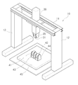
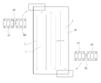
도 1은 본 발명의 일 실시예에 따른 금속판재의 곡면 성형장치를 도시한 사시도이다.
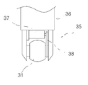
도 2는 본 발명의 일 실시예에 따른 곡면 성형장치의 상부 램 및 상부 롤러 구조를 도시한 정면도이다.
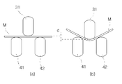
도 3은 본 발명의 일 실시예에 따른 곡면 성형장치의 상부 롤러의 압하에 의해 금속판재의 곡면이 성형되는 원리를 도시한 도면이다.
도 4는 본 발명의 일 실시예에 따른 곡면 성형장치를 통해 금속판재가 복수의 롤라인을 형성하면서 성형되는 방법을 나타낸 도면이다.
도 5는 본 발명의 일 실시예에 따른 곡면 성형장치의 제1 및 제2 하부 롤러의 배열 형태를 예시한 도면이다.
도 6은 본 발명의 일 실시예에 따른 곡면 성형장치에 의해 금속판재의 단일횡방향 곡면이 성형되는 방법을 도시한 도면이다.
도 7은 본 발명의 일 실시예에 따른 곡면 성형장치에 의해 금속판재의 단일종방향 곡면이 성형되는 방법을 도시한 도면이다.
도 8은 본 발명의 일 실시예에 따른 곡면 성형장치에 의해 금속판재의 오목형 이중곡면이 성형되는 방법을 도시한 제1실시형태이다.
도 9는 본 발명의 일 실시예에 따른 곡면 성형장치에 의해 금속판재의 오목형 이중곡면이 성형되는 방법을 도시한 제2실시형태이다.
도 10은 본 발명의 일 실시예에 따른 곡면 성형장치에 의해 금속판재의 안장형 이중곡면이 성형되는 방법을 도시한 제1실시형태이다.
도 11은 본 발명의 일 실시예에 따른 곡면 성형장치에 의해 금속판재의 안장형 이중곡면이 성형되는 방법을 도시한 제2실시형태이다.
도 12는 본 발명의 일 실시예에 따른 곡면 성형장치에 의해 금속판재의 비틀림 곡면이 성형되는 방법을 도시한 도면이다.
도 13은 본 발명의 일 실시예에 따른 곡면 성형장치에서 제1 및 제2 하부 롤러의 배열 방향 설정을 통해 주곡률 방향이 조절되는 상태를 설명하는 도면이다. 1 is a perspective view showing a curved surface forming apparatus of a metal sheet according to an embodiment of the present invention.
Figure 2 is a front view showing the upper ram and the upper roller structure of the curved surface forming apparatus according to an embodiment of the present invention.
3 is a view showing a principle that the curved surface of the metal plate is formed by the reduction of the upper roller of the curved surface forming apparatus according to an embodiment of the present invention.
4 is a view showing a method of forming a metal sheet while forming a plurality of roll lines through the curved surface forming apparatus according to an embodiment of the present invention.
5 is a view illustrating an arrangement of the first and second lower rollers of the curved surface forming apparatus according to an embodiment of the present invention.
FIG. 6 is a view illustrating a method in which a single transverse curved surface of a metal sheet is molded by a curved surface forming apparatus according to an embodiment of the present invention.
FIG. 7 is a view illustrating a method in which a single longitudinal curved surface of a metal sheet is formed by a curved surface forming apparatus according to an embodiment of the present invention.
FIG. 8 is a first embodiment showing a method of forming a concave double curved surface of a metal sheet by a curved forming apparatus according to an embodiment of the present invention.
FIG. 9 is a second embodiment showing a method of forming a concave double curved surface of a metal sheet by a curved surface forming apparatus according to an embodiment of the present invention.
FIG. 10 is a first embodiment showing a method in which a saddle-shaped double curved surface of a metal sheet is molded by a curved forming apparatus according to an embodiment of the present invention.
FIG. 11 is a second embodiment showing a method of forming a saddle-shaped double curved surface of a metal sheet by a curved forming apparatus according to an embodiment of the present invention.
FIG. 12 is a view illustrating a torsion curved surface of a metal plate material by a curved surface forming apparatus according to an embodiment of the present invention.
13 is a view illustrating a state in which the main curvature direction is adjusted by setting the arrangement direction of the first and second lower rollers in the curved forming apparatus according to the embodiment of the present invention.
이하, 본 발명의 바람직한 실시예를 첨부된 도면을 참조하여 상세히 설명한다. Hereinafter, preferred embodiments of the present invention will be described in detail with reference to the accompanying drawings.
도 1 내지 도 12는 본 발명에 의한 금속판재의 곡면 성형장치 및 그 성형방법을 도시한 도면이다. 1 to 12 are views showing a curved surface forming apparatus and a forming method of a metal sheet according to the present invention.
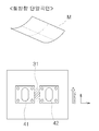
도 1 및 도 2에 도시된 바와 같이, 본 발명의 일 실시예에 따른 금속판재의 곡면 성형장치는 상부 롤러(31), 상부 롤러(31)의 하측에 배치되는 제1 및 제2 하부 롤러(41, 42)를 포함한다. 1 and 2, the curved surface forming apparatus of the metal sheet according to an embodiment of the present invention is the
상부 롤러(31)는 상부 램(35)측에 회전가능하게 설치되고, 도 2에 도시된 바와 같이 상부 램(35)에는 구동모터(37)가 설치되어 있으며, 구동모터(37)와 상부 롤러(31)의 회전축 사이에는 벨트전동기구(38) 등과 같은 전동기구가 설치되고, 이에 상부 롤러(31)는 구동모터(37)에 의해 회전구동하도록 구성된다. The
상부 램(35)은 프레임(10) 측에 상하 이동가능하게 설치되고, 상부 램(35)의 상부에는 프레스유닛(36)이 연결되며, 프레스유닛(36) 내에는 상부 램(35)을 상하방향으로 이동시키는 상하이동메커니즘(미도시)이 설치된다. 상하이동메커니즘은 이송스크류, 실린더 등과 같이 상부 램(35)의 안정적인 상하 이동을 구현할 수 잇는 다양한 구조로 구성될 수 있다. The
프레임(10)은 길이방향으로 길게 연장된 상부 수평거더(11) 및 상부 수평거더(11)의 양단부에 구비된 한 쌍의 프레임 레그(12)로 구성된다. 그리고, 수평거더(11) 측에는 프레스유닛(36)이 설치되고, 프레스유닛(36)은 수평거더(11)의 길이방향으로 이동가능하게 설치될 수 있다. The
제1 및 제2 하부 롤러(41, 42) 각각은 제1 및 제2 하부 램(43, 44) 측에 개별적으로 회전가능하게 설치되고, 특히 제1하부 롤러(41)는 제1하부 램(43) 측에 자유 회전하도록 회전지지되며, 제2하부 롤러(42)는 제2하부 램(44) 측에 자유 회전하도록 회전지지된다.Each of the first and second
제1 및 제2 하부 램(43, 44)은 하부 스테이지(45) 측에 상하 이동가능하게 설치될 수 있다. 제1 및 제2 하부 램(43, 44)은 하부 스테이지(45)의 상면에서 다양한 수평방향(예컨대, 금속판재(M)의 종방향, 횡방향, 사선방향 등)으로 이동가능하게 설치될 수 있고, 이에 제1 및 제2 하부 램(43, 44)은 하부 스테이지(45)의 상면에서 수평방향으로 다양하게 그 위치가 조절될 수 있다. 그리고, 하부 스테이지(45)의 내부에는 제1 및 제2 하부 램(43, 44)을 수평방향으로 자유롭게 이동시키는 이동메커니즘(미도시)이 내장되고, 이동메커니즘은 이송스크류, 실린더 등과 같이 제1 및 제2 하부 램(43, 44)의 정밀한 수평이동을 구현할 수 있는 다양한 구조로 구성될 수 있다. The first and second
도 5(a) 내지 도 5(d)를 참조하여 보면, 제1 및 제2 하부 롤러(41, 42)는 도 5(a)와 같이 횡방향으로 이격되어 배열될 수 있고, 도 5(b)와 같이 종방향으로 이격되어 배열될 수 있으며, 도 5(c) 및 도 5(d)와 같이 사선방향으로 이격되어 배열될 수 있다. 그리고, 제1 및 제2 하부 롤러(41, 42)는 그 이격간격이 적절히 조절될 수 있다. Referring to FIGS. 5A to 5D, the first and second
도 3에 도시된 바와 같이, 프레스유닛(36)의 상하 이동작동에 의해 상부 램(35) 및 상부 롤러(31)가 하향 이동하고, 이에 상부 롤러(31)는 제1 및 제2 하부 롤러(41, 42)에 의해 받쳐진 금속판재(M)의 상면을 수직으로 압하(가압)함에 따라 금속판재(M)의 굽힘성형을 수행한다. 이러한 굽힘 성형을 통해 금속판재(M) 측에 굽힘 변형이 생기고, 이러한 굽힘 변형을 통해 곡면이 얻어진다. 이 때, 금속판재(M)의 굽힘 변형량은 상부 롤러(31)의 압하량(d)에 의해 결정될 수 있다. As shown in FIG. 3, the
이와 같이, 상부 롤러(31)는 프레스유닛(36)에 의해 금속판재(M)의 상면을 압하함과 더불어 구동모터(37)에 의해 회전구동하고, 제1 및 제2 하부 롤러(41, 42)은 자유회전하면서 금속판재(M)의 하면과 구름접촉하면서 지지함으로써 금속판재(M)는 상부 롤러(31)와 제1 및 제2 하부 롤러(41, 42)와의 마찰을 통해 이송될 수 있다. As such, the
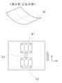
특히, 본 발명에 의한 곡면 성형방법에 의하면, 금속판재(M)는 상부 롤러(31)와 하부 롤러(41, 42)들 사이에서 종방향으로 이송됨이 바람직하고, 이에 도 4와 같이 상부 롤러(31)의 압하에 의해 금속판재(M)측에는 종방향으로 롤라인(L)이 형성된다. 하나의 롤라인(L)이 형성된 후에, 금속판재(M)를 횡방향으로 이동시켜 상부 롤러(31)와 하부 롤러(41, 42)에 의한 성형 위치를 횡방향으로 이격시켜 롤라인(L)을 여러번 반복적으로 형성시킬 수 있고, 이에 도 4와 같이 복수의 롤라인(L)이 횡방향으로 나란히 형성됨에 따라 금속판재(M)의 곡면을 점진적으로 성형할 수 있다. In particular, according to the curved forming method according to the present invention, the metal plate (M) is preferably conveyed in the longitudinal direction between the
도 6 내지 도 11은 제1 및 제2 하부 롤러(41, 42)의 배열 상태에 따른 금속판재의 곡면 성형방법을 도시한 도면이다. 6 to 11 illustrate a method of forming a curved surface of a metal sheet according to an arrangement state of the first and second
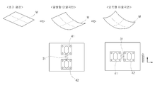
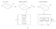
도 6을 참조하면, 제1 및 제2 하부 롤러(41, 42)가 금속판재의 횡방향으로 이격되어 배열되고, 이런 상태에서 상부 롤러(31)의 압하 및 회전구동에 의해 금속판재(M)를 종방향으로 이송시킴에 따라 단일횡곡률 곡면을 성형할 수 있다. Referring to FIG. 6, the first and second
도 7을 참조하면, 제1 및 제2 하부 롤러(41, 42)가 금속판재(M)의 종방향으로 이격되어 배열되고, 이런 상태에서 상부 롤러(31)의 압하 및 회전구동에 의해 금속판재(M)를 종방향으로 이송시킴에 따라 단일종곡률 곡면을 성형할 수 있다. Referring to FIG. 7, the first and second
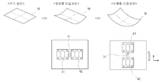
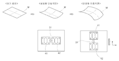
도 8을 참조하면, 제1 및 제2 하부 롤러(41, 42)를 금속판재(M)의 횡방향으로 이격시켜 배열한 상태에서 금속판재(M)를 종방향으로 이송시켜 단일횡곡률 곡면을 성형한 후에, 제1 및 제2 하부 롤러(41, 42)를 금속판재(M)의 종방향으로 이격시켜 배열한 상태에서 금속판재(M)를 종방향으로 이송시킴으로써 금속판재(M) 측에 종곡률 곡면을 추가함으로써 오목형 이중곡면을 성형할 수 있다. Referring to FIG. 8, in a state in which the first and second
도 9를 참조하면, 제1 및 제2 하부 롤러(41, 42)를 금속판재(M)의 종방향으로 이격시켜 배열한 상태에서 금속판재(M)를 종방향으로 이송시킴으로써 단일종곡률 곡면을 성형한 후에, 제1 및 제2 하부 롤러(41, 42)를 금속판재(M)의 횡방향으로 이격시켜 배열한 상태에서 금속판재(M)를 종방향으로 이송시켜 금속판재(M) 측에 횡곡률 곡면을 추가함으로써 오목형 이중곡면을 성형할 수 있다. Referring to FIG. 9, a single longitudinal curvature curved surface is transferred by vertically transferring the metal sheet M in a state in which the first and second
도 10을 참조하면, 제1 및 제2 하부 롤러(41, 42)를 금속판재(M)의 횡방향으로 이격시켜 배열한 상태에서 금속판재(M)를 종방향으로 이송시켜 단일횡곡률 곡면을 성형한 후에, 제1 및 제2 하부 롤러(41, 42)를 금속판재의 종방향으로 이격시켜 배열한 상태에서 금속판재(M)를 뒤집어 종방향으로 이송시킴으로써 금속판재(M) 측에 종곡률 곡면을 추가함으로써 안장형 이중곡면을 성형할 수 있다. Referring to FIG. 10, in a state where the first and second
도 11을 참조하면, 제1 및 제2 하부 롤러(41, 42)를 금속판재(M)의 종방향으로 이격시켜 배열한 상태에서 금속판재(M)를 종방향으로 이송시켜 단일종곡률 곡면을 성형한 후에, 제1 및 제2 하부 롤러(41, 42)를 금속판재(M)의 횡방향으로 이격시켜 배열한 상태에서 금속판재(M)를 뒤집어 종방향으로 이송시킴으로써 금속판재(M) 측에 횡곡률 곡면을 추가함으로써 오목형 이중곡면을 성형할 수 있다. Referring to FIG. 11, in a state in which the first and second
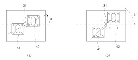
도 12를 참조하면, 제1 및 제2 하부 롤러(41, 42)가 금속판재의 사선방향으로 이격되어 배열되고, 이런 배열 상태에서 상부 롤러(31)의 압하 및 회저구동에 의해 금속판재(M)를 종방향으로 이송시키면 비틀림 곡면을 성형할 수 있다. 금속판재(M)는 제1 및 제2 하부 롤러(41, 42)의 배열 방향을 따라 큰 굽힘 모멘트(bending moment)를 받고, 이에 금속판재(M) 측에는 그 배열 방향으로 주곡률(major curvature)가 생성된다. 이에 따라, 하부 롤러(41, 42)의 배열방향 조절을 통해 금속판재(M)의 주곡률방향을 변화시켜 비틀림방향을 시계방향 또는 반시계방향으로 조절하는 용이해진다. Referring to FIG. 12, the first and second
도 13을 참조하면, 도 13(a) 및 도 13(b)와 같이 제1 및 제2 하부 롤러(41, 42)의 사선방향 배열 각도(a, a') 등과 같이 다양한 설정할 수 있다. 이러한 제1 및 제2 하부 롤러(41, 42)의 다양한 배열방향 설정을 통해 주곡률 방향을 임의대로 자유롭게 조절할 수 있고, 이에 보다 다양한 곡면을 정밀하게 성형할 수 있다. Referring to FIG. 13, various settings may be made, such as the diagonal arrangement angles a and a 'of the first and second
이와 같이, 본 발명은 단일의 상부 롤러(31)와, 제1 및 제2 하부 롤러(41, 42)만을 구성함에 따라 장치 전체 시스템이 매우 단순하여 시스템의 제어가 매우 간편하고, 제조비용이 절감되는 장점이 있다. As such, the present invention comprises only a single
그리고, 본 발명은 기구학적 구속 조건 없이 한 쌍의 하부 롤러(41, 42)의 수평 이동이 용이하고, 이에 보다 금속판재의 보다 다양한 곡면 성형을 효과적으로 구현할 수 있는 장점이 있다. In addition, the present invention has an advantage that the horizontal movement of the pair of
또한, 본 발명은 제1 및 제2 하부 롤러(41, 42)의 자유로운 수평이동을 통해 금속판재의 굽힘 방향을 보다 폭 넓은 범위로 조절할 수 있는 장점이 있다. In addition, the present invention has the advantage that the bending direction of the metal plate material can be adjusted in a wider range through the free horizontal movement of the first and second lower rollers (41, 42).
10: 프레임 31: 상부 롤러
35: 상부 램 36: 프레스유닛
37: 구동모터 38: 전동기구
41: 제1하부 롤러 42: 제2하부 롤러
43: 제1하부 램 44: 제2하부 램
45: 하부 스테이지 M: 금속판재10: frame 31: upper roller
35: upper ram 36: press unit
37: drive motor 38: electric drive
41: first lower roller 42: second lower roller
43: first lower ram 44: second lower ram
45: lower stage M: metal plate
Claims (18)
프레임 측에 상하이동가능하게 설치된 상부 램;
상기 상부 램 측에 회전가능하게 설치된 상부 롤러;
하부 스테이지 측에 상하이동가능하게 설치된 제1 및 제2 하부 램;
상기 제1 및 제2 하부 램 측에 회전가능하게 각각 설치된 제1 및 제2 하부 롤러;를 포함하고,
상기 제1 및 제2 하부 램은 상기 하부 스테이지의 상면에서 수평방향으로 이동가능하게 설치되는 것을 특징으로 하는 금속판재의 곡면 성형장치.A curved surface forming apparatus of a metal sheet for forming a curved surface of a metal sheet,
An upper ram mounted on the frame side so as to be movable;
An upper roller rotatably installed on the upper ram side;
First and second lower rams mounted on the lower stage side in a movable manner;
And first and second lower rollers rotatably installed on the first and second lower ram sides, respectively.
And the first and second lower rams are installed to be movable in a horizontal direction from an upper surface of the lower stage.
상기 상부 롤러는 상기 상부 램 측에 설치된 구동모터에 의해 회전구동하는 것을 특징으로 하는 금속판재의 곡면 성형장치.The method according to claim 1,
The upper roller is a curved surface forming apparatus of a metal plate material, characterized in that the rotation drive by a drive motor installed on the upper ram side.
상기 프레임은 길이방향으로 길게 연장된 상부 수평거더 및 상기 상부 수평거더의 양단부에 구비된 한 쌍의 프레임 레그로 구성되는 것을 특징으로 하는 금속판재의 곡면 성형장치.The method according to claim 1,
The frame is a curved surface forming apparatus of a metal plate material, characterized in that consisting of a pair of frame legs provided on both ends of the upper horizontal girder and the upper horizontal girder extending in the longitudinal direction.
상기 상부 램의 상부에는 프레스유닛이 연결되고, 상기 프레스유닛은 상기 상부 수평거더의 길이방향으로 이동가능하게 설치되는 것을 특징으로 하는 금속판재의 곡면 성형장치.The method according to claim 3,
A press unit is connected to an upper portion of the upper ram, and the press unit is curved surface forming apparatus of the metal plate material, characterized in that installed to be movable in the longitudinal direction of the upper horizontal girder.
상기 프레스유닛 내에는 상기 상부 램을 상하방향으로 이동시키는 상하이동메커니즘이 설치되는 것을 특징으로 하는 금속판재의 곡면 성형장치.The method of claim 4,
And a shanghai copper mechanism for moving the upper ram in a vertical direction in the press unit.
상기 제1하부 롤러는 상기 제1하부 램 측에 자유 회전하도록 회전지지되고, 상기 제2하부 롤러는 상기 제2하부 램 측에 자유 회전하도록 회전지지되는 것을 특징으로 하는 금속판재의 곡면 성형장치.The method according to claim 1,
And the first lower roller is rotatably supported on the first lower ram side, and the second lower roller is rotatably supported on the second lower ram side.
상기 하부 스테이지의 내부에는 상기 제1 및 제2 하부 램을 수평방향으로 자유롭게 이동시키는 이동메커니즘이 내장되는 것을 특징으로 하는 금속판재의 곡면 성형장치.The method of claim 6,
The inside of the lower stage curved surface forming apparatus of the metal plate, characterized in that the movement mechanism for freely moving the first and second lower ram in the horizontal direction is embedded.
구동모터에 의해 회전가능하게 설치된 상부 롤러; 및
상기 상부 롤러의 하측에 배치되고, 회전가능하게 설치된 제1 및 제2 하부 롤러;를 포함하고,
상기 제1 및 제2 하부 램은 수평방향으로 이동가능하게 설치되는 것을 특징으로 하는 금속판재의 곡면 성형장치.A curved surface forming apparatus of a metal sheet for forming a curved surface of a metal sheet,
An upper roller rotatably installed by a drive motor; And
And first and second lower rollers disposed below the upper roller and rotatably installed.
The first and second lower rams are curved forming apparatus of a metal plate, characterized in that the movable in the horizontal direction.
상기 금속판재의 하면을 상기 제1 및 제2 하부 롤러 측에 지지시킨 상태에서 상기 금속판재의 상면에 상기 상부 롤러를 압하와 동시에 회전구동시킴으로써 금속판재를 종방향으로 이송시켜 금속판재의 곡면을 성형하는 것을 특징으로 하는 금속판재의 곡면 성형방법.By using the upper roller and the first and second lower rollers disposed below the upper roller to form a curved surface of the metal sheet material,
The upper surface of the metal sheet is supported on the first and second lower rollers while the upper roller is pressed down and rotated simultaneously with the lower surface of the metal sheet to transfer the metal sheet in the longitudinal direction to form the curved surface of the metal sheet. The curved surface forming method of the metal sheet material characterized in that.
상기 상부 롤러의 압하 및 회전구동에 의한 금속판재의 종방향 이송을 횡방향으로 이동하면서 여러번 반복함으로써 금속판재의 곡면을 점진적으로 성형하는 것을 특징으로 하는 금속판재의 곡면 성형방법.The method according to claim 9,
The method of forming a curved surface of a metal sheet material, characterized in that the curved surface of the metal sheet material is gradually formed by repeating the longitudinal conveyance of the metal sheet material by the lowering and rotational driving of the upper roller in the transverse direction several times.
상기 상부 롤러의 압하 및 회전구동에 의해 상기 금속판재 측에 단일의 롤라인을 형성한 후에, 상기 금속판재를 횡방향으로 이동시켜 상부 롤러의 회전구동에 의해 이송시키는 과정을 여러번 반복함으로써 복수의 롤라인이 형성되도록 성형하는 것을 특징으로 하는 금속판재의 곡면 성형방법.The method according to claim 9,
After forming a single roll line on the side of the metal plate by pressing and rotating the upper roller, a plurality of rolls are repeated by repeating the process of moving the metal plate in the transverse direction and conveying it by rotation of the upper roller. Curved forming method of a metal plate material, characterized in that the molding to form a phosphorus.
상기 제1 및 제2 하부 롤러를 금속판재의 횡방향으로 이격시켜 배열한 상태에서 상기 금속판재를 종방향으로 이송시킴으로써 단일횡곡률 곡면을 성형하는 것을 특징으로 하는 금속판재의 곡면 성형방법.The method according to claim 9,
Forming a single transverse curvature curved surface by transferring the metal sheet in the longitudinal direction in a state in which the first and second lower rollers are arranged spaced apart in the transverse direction of the metal sheet.
상기 제1 및 제2 하부 롤러를 금속판재의 종방향으로 이격시켜 배열한 상태에서 상기 금속판재를 종방향으로 이송시킴으로써 단일종곡률 곡면을 성형하는 것을 특징으로 하는 금속판재의 곡면 성형방법.The method of claim 9,
Forming a single longitudinal curvature curved surface by conveying the metal sheet in the longitudinal direction in a state in which the first and second lower rollers are arranged spaced apart in the longitudinal direction of the metal sheet.
상기 제1 및 제2 하부 롤러를 금속판재의 사선방향으로 이격시켜 배열한 상태에서 상기 금속판재를 종방향으로 이송시킴으로써 비틀림 곡면을 성형하는 것을 특징으로 하는 금속판재의 곡면 성형방법.The method according to claim 9,
And twisting curved surfaces by transferring the metal sheet in the longitudinal direction while arranging the first and second lower rollers in the diagonal direction of the metal sheet.
상기 제1 및 제2 하부 롤러를 금속판재의 횡방향으로 이격시켜 배열한 상태에서 상기 금속판재를 종방향으로 이송시켜 단일횡곡률 곡면을 성형한 후에,
상기 제1 및 제2 하부 롤러를 금속판재의 종방향으로 이격시켜 배열한 상태에서 상기 금속판재를 종방향으로 이송시킴으로써 금속판재 측에 종곡률 곡면을 추가함으로써 오목형 이중곡면을 성형하는 것을 특징으로 하는 금속판재의 곡면 성형방법.The method according to claim 9,
After the first and second lower rollers are arranged to be spaced apart in the transverse direction of the metal sheet, the metal sheet is transferred in the longitudinal direction to form a single transverse curvature surface.
Forming a concave double curved surface by adding a longitudinal curvature surface to the metal plate by transferring the metal plate in the longitudinal direction in a state in which the first and second lower rollers are arranged spaced apart in the longitudinal direction of the metal plate. Curved surface forming method of a metal sheet material.
상기 제1 및 제2 하부 롤러를 금속판재의 종방향으로 이격시켜 배열한 상태에서 상기 금속판재를 종방향으로 이송시킴으로써 단일종곡률 곡면을 성형한 후에,
상기 제1 및 제2 하부 롤러를 금속판재의 횡방향으로 이격시켜 배열한 상태에서 상기 금속판재를 종방향으로 이송시켜 금속판재 측에 횡곡률 곡면을 추가함으로써 오목형 이중곡면을 성형하는 것을 특징으로 하는 금속판재의 곡면 성형방법.The method according to claim 9,
After molding the single longitudinal curvature surface by transferring the metal sheet in the longitudinal direction while arranging the first and second lower rollers spaced apart in the longitudinal direction of the metal sheet,
Forming a concave double curved surface by adding the transverse curvature to the metal plate side by transferring the metal plate in the longitudinal direction in the state in which the first and second lower rollers are arranged spaced apart in the horizontal direction of the metal plate member. Curved surface forming method of a metal sheet material.
상기 제1 및 제2 하부 롤러를 금속판재의 횡방향으로 이격시켜 배열한 상태에서 상기 금속판재를 종방향으로 이송시켜 단일횡곡률 곡면을 성형한 후에,
상기 제1 및 제2 하부 롤러를 금속판재의 종방향으로 이격시켜 배열한 상태에서 상기 금속판재를 뒤집어 종방향으로 이송시킴으로써 금속판재 측에 종곡률 곡면을 추가함으로써 안장형 이중곡면을 성형하는 것을 특징으로 하는 금속판재의 곡면 성형방법.The method according to claim 9,
After the first and second lower rollers are arranged to be spaced apart in the transverse direction of the metal sheet, the metal sheet is transferred in the longitudinal direction to form a single transverse curvature surface.
Forming a saddle-shaped double curved surface by adding a longitudinal curvature curved surface to the metal sheet by inverting the metal sheet and in the longitudinal direction while arranging the first and second lower rollers spaced apart in the longitudinal direction of the metal sheet. Curved molding method of metal sheet material.
상기 제1 및 제2 하부 롤러를 금속판재의 종방향으로 이격시켜 배열한 상태에서 상기 금속판재를 종방향으로 이송시켜 단일종곡률 곡면을 성형한 후에,
상기 제1 및 제2 하부 롤러를 금속판재의 횡방향으로 이격시켜 배열한 상태에서 상기 금속판재를 뒤집어 종방향으로 이송시켜 금속판재 측에 횡곡률 곡면을 추가함으로써 안장형 이중곡면을 성형하는 것을 특징으로 하는 금속판재의 곡면 성형방법.The method according to claim 9,
After the first and second lower rollers are arranged to be spaced apart in the longitudinal direction of the metal sheet, the metal sheet is transferred in the longitudinal direction to form a single longitudinal curvature surface.
Forming a saddle-shaped double curved surface by adding the transverse curvature surface to the metal plate side by inverting and transporting the metal plate member in the longitudinal direction while arranging the first and second lower rollers in the horizontal direction of the metal plate member. Curved molding method of metal sheet material.
Priority Applications (1)
| Application Number | Priority Date | Filing Date | Title |
|---|---|---|---|
| KR1020100138953A KR20120077116A (en) | 2010-12-30 | 2010-12-30 | Apparatus and method for curvature forming of metal plate |
Applications Claiming Priority (1)
| Application Number | Priority Date | Filing Date | Title |
|---|---|---|---|
| KR1020100138953A KR20120077116A (en) | 2010-12-30 | 2010-12-30 | Apparatus and method for curvature forming of metal plate |
Publications (1)
| Publication Number | Publication Date |
|---|---|
| KR20120077116A true KR20120077116A (en) | 2012-07-10 |
Family
ID=46710659
Family Applications (1)
| Application Number | Title | Priority Date | Filing Date |
|---|---|---|---|
| KR1020100138953A KR20120077116A (en) | 2010-12-30 | 2010-12-30 | Apparatus and method for curvature forming of metal plate |
Country Status (1)
| Country | Link |
|---|---|
| KR (1) | KR20120077116A (en) |
Cited By (3)
| Publication number | Priority date | Publication date | Assignee | Title |
|---|---|---|---|---|
| CN108838254A (en) * | 2018-06-15 | 2018-11-20 | 宁波市创捷自动化有限公司 | A kind of vehicle dormer window rail end roll bending tooling |
| KR20230075533A (en) * | 2021-11-23 | 2023-05-31 | 한국생산기술연구원 | High-efficiency bipolar separator for fuel cell with large area and free-curved surface, and manufacturing methods for the same |
| CN116422744A (en) * | 2023-06-13 | 2023-07-14 | 湖南益格特钢科技有限公司 | Special-shaped steel pipe forming die |
-
2010
- 2010-12-30 KR KR1020100138953A patent/KR20120077116A/en not_active Application Discontinuation
Cited By (5)
| Publication number | Priority date | Publication date | Assignee | Title |
|---|---|---|---|---|
| CN108838254A (en) * | 2018-06-15 | 2018-11-20 | 宁波市创捷自动化有限公司 | A kind of vehicle dormer window rail end roll bending tooling |
| CN108838254B (en) * | 2018-06-15 | 2023-10-20 | 宁波市创捷自动化有限公司 | Automobile skylight guide rail end roll bending tool |
| KR20230075533A (en) * | 2021-11-23 | 2023-05-31 | 한국생산기술연구원 | High-efficiency bipolar separator for fuel cell with large area and free-curved surface, and manufacturing methods for the same |
| CN116422744A (en) * | 2023-06-13 | 2023-07-14 | 湖南益格特钢科技有限公司 | Special-shaped steel pipe forming die |
| CN116422744B (en) * | 2023-06-13 | 2023-08-18 | 湖南益格特钢科技有限公司 | Special-shaped steel pipe forming die |
Similar Documents
| Publication | Publication Date | Title |
|---|---|---|
| CN101531452B (en) | Method and apparatus for bending a glass sheet | |
| US9174258B2 (en) | Apparatus and process for forming profiles with a variable height by means of cold rolling | |
| CN104785598B (en) | Rolling edge folding machine | |
| KR101767543B1 (en) | Shape fitting type plate supporting apparatus for curvature forming system | |
| CN104349678A (en) | Apparatus for producing a flat rolled continuously conveyed strip of dough | |
| KR20060065575A (en) | Line array roll set for the manufacture of various doubly curved sheet metals and forming method thereby | |
| KR20120077116A (en) | Apparatus and method for curvature forming of metal plate | |
| CN208083133U (en) | A kind of corrugated plating forming press | |
| CN101569910B (en) | Panel transportation device | |
| CN217191824U (en) | Crumple type bending machine | |
| KR20170081905A (en) | COMPOUND PRESS Device | |
| KR101834499B1 (en) | Cutting apparatus for roll forming products | |
| KR101739454B1 (en) | Feeding apparatus for curvature forming of metal plate and method for feeding thereof | |
| CN102099131B (en) | Apparatus for straightening a metallic material | |
| KR20120136075A (en) | Supporting apparatus for curvature forming of metal plate | |
| CN109969728B (en) | High-efficiency material conveying method | |
| EP2448694B1 (en) | Continuously smoothly adjustable and self-aligning variable width roll forming apparatus | |
| KR100874597B1 (en) | The double nc roll feeder for possible 1 shaft 2 line control | |
| WO2010113979A1 (en) | Device and method for bending glass sheet | |
| CN215358907U (en) | A setting device that is used for panel processing to prevent thermal deformation | |
| CN205441884U (en) | Dough sheet turns to device | |
| CN216503935U (en) | Roller type wire drawing machine | |
| CN217436748U (en) | Four-roller feeder | |
| CN219169433U (en) | Feeding and compacting device of tile pressing machine | |
| CN216655923U (en) | Corrugated plate three-roller arc bending machine |
Legal Events
| Date | Code | Title | Description |
|---|---|---|---|
| A201 | Request for examination | ||
| E601 | Decision to refuse application |