KR20120054879A - Method for planing collision avoidance path of car-like mobile robot and parking assist system using the same - Google Patents
Method for planing collision avoidance path of car-like mobile robot and parking assist system using the same Download PDFInfo
- Publication number
- KR20120054879A KR20120054879A KR1020100116244A KR20100116244A KR20120054879A KR 20120054879 A KR20120054879 A KR 20120054879A KR 1020100116244 A KR1020100116244 A KR 1020100116244A KR 20100116244 A KR20100116244 A KR 20100116244A KR 20120054879 A KR20120054879 A KR 20120054879A
- Authority
- KR
- South Korea
- Prior art keywords
- motion
- path
- mobile robot
- vehicle
- obstacle
- Prior art date
Links
- 238000000034 method Methods 0.000 title claims abstract description 108
- 230000033001 locomotion Effects 0.000 claims abstract description 269
- 238000004364 calculation method Methods 0.000 claims description 26
- 238000006073 displacement reaction Methods 0.000 claims description 15
- 230000008859 change Effects 0.000 claims description 8
- 230000007306 turnover Effects 0.000 claims description 4
- 238000004088 simulation Methods 0.000 description 24
- 230000008569 process Effects 0.000 description 13
- 238000006243 chemical reaction Methods 0.000 description 7
- 238000010586 diagram Methods 0.000 description 7
- 238000013459 approach Methods 0.000 description 4
- 238000007781 pre-processing Methods 0.000 description 4
- 230000000694 effects Effects 0.000 description 3
- 230000007613 environmental effect Effects 0.000 description 3
- 230000007704 transition Effects 0.000 description 3
- 238000004422 calculation algorithm Methods 0.000 description 2
- 239000000284 extract Substances 0.000 description 2
- 238000013528 artificial neural network Methods 0.000 description 1
- 230000000052 comparative effect Effects 0.000 description 1
- 230000005494 condensation Effects 0.000 description 1
- 238000009833 condensation Methods 0.000 description 1
- 230000001419 dependent effect Effects 0.000 description 1
- 238000000691 measurement method Methods 0.000 description 1
- 238000012986 modification Methods 0.000 description 1
- 230000004048 modification Effects 0.000 description 1
- 238000005457 optimization Methods 0.000 description 1
- 239000002245 particle Substances 0.000 description 1
- 230000003252 repetitive effect Effects 0.000 description 1
- 238000012876 topography Methods 0.000 description 1
Images
Classifications
-
- B—PERFORMING OPERATIONS; TRANSPORTING
- B60—VEHICLES IN GENERAL
- B60W—CONJOINT CONTROL OF VEHICLE SUB-UNITS OF DIFFERENT TYPE OR DIFFERENT FUNCTION; CONTROL SYSTEMS SPECIALLY ADAPTED FOR HYBRID VEHICLES; ROAD VEHICLE DRIVE CONTROL SYSTEMS FOR PURPOSES NOT RELATED TO THE CONTROL OF A PARTICULAR SUB-UNIT
- B60W30/00—Purposes of road vehicle drive control systems not related to the control of a particular sub-unit, e.g. of systems using conjoint control of vehicle sub-units
- B60W30/08—Active safety systems predicting or avoiding probable or impending collision or attempting to minimise its consequences
- B60W30/095—Predicting travel path or likelihood of collision
-
- B—PERFORMING OPERATIONS; TRANSPORTING
- B25—HAND TOOLS; PORTABLE POWER-DRIVEN TOOLS; MANIPULATORS
- B25J—MANIPULATORS; CHAMBERS PROVIDED WITH MANIPULATION DEVICES
- B25J5/00—Manipulators mounted on wheels or on carriages
- B25J5/02—Manipulators mounted on wheels or on carriages travelling along a guideway
-
- B—PERFORMING OPERATIONS; TRANSPORTING
- B60—VEHICLES IN GENERAL
- B60W—CONJOINT CONTROL OF VEHICLE SUB-UNITS OF DIFFERENT TYPE OR DIFFERENT FUNCTION; CONTROL SYSTEMS SPECIALLY ADAPTED FOR HYBRID VEHICLES; ROAD VEHICLE DRIVE CONTROL SYSTEMS FOR PURPOSES NOT RELATED TO THE CONTROL OF A PARTICULAR SUB-UNIT
- B60W30/00—Purposes of road vehicle drive control systems not related to the control of a particular sub-unit, e.g. of systems using conjoint control of vehicle sub-units
- B60W30/10—Path keeping
-
- B—PERFORMING OPERATIONS; TRANSPORTING
- B62—LAND VEHICLES FOR TRAVELLING OTHERWISE THAN ON RAILS
- B62D—MOTOR VEHICLES; TRAILERS
- B62D15/00—Steering not otherwise provided for
- B62D15/02—Steering position indicators ; Steering position determination; Steering aids
- B62D15/027—Parking aids, e.g. instruction means
-
- B—PERFORMING OPERATIONS; TRANSPORTING
- B60—VEHICLES IN GENERAL
- B60W—CONJOINT CONTROL OF VEHICLE SUB-UNITS OF DIFFERENT TYPE OR DIFFERENT FUNCTION; CONTROL SYSTEMS SPECIALLY ADAPTED FOR HYBRID VEHICLES; ROAD VEHICLE DRIVE CONTROL SYSTEMS FOR PURPOSES NOT RELATED TO THE CONTROL OF A PARTICULAR SUB-UNIT
- B60W2552/00—Input parameters relating to infrastructure
- B60W2552/50—Barriers
-
- B—PERFORMING OPERATIONS; TRANSPORTING
- B60—VEHICLES IN GENERAL
- B60W—CONJOINT CONTROL OF VEHICLE SUB-UNITS OF DIFFERENT TYPE OR DIFFERENT FUNCTION; CONTROL SYSTEMS SPECIALLY ADAPTED FOR HYBRID VEHICLES; ROAD VEHICLE DRIVE CONTROL SYSTEMS FOR PURPOSES NOT RELATED TO THE CONTROL OF A PARTICULAR SUB-UNIT
- B60W2710/00—Output or target parameters relating to a particular sub-units
- B60W2710/20—Steering systems
- B60W2710/207—Steering angle of wheels
-
- B—PERFORMING OPERATIONS; TRANSPORTING
- B60—VEHICLES IN GENERAL
- B60Y—INDEXING SCHEME RELATING TO ASPECTS CROSS-CUTTING VEHICLE TECHNOLOGY
- B60Y2300/00—Purposes or special features of road vehicle drive control systems
- B60Y2300/08—Predicting or avoiding probable or impending collision
- B60Y2300/095—Predicting travel path or likelihood of collision
-
- B—PERFORMING OPERATIONS; TRANSPORTING
- B60—VEHICLES IN GENERAL
- B60Y—INDEXING SCHEME RELATING TO ASPECTS CROSS-CUTTING VEHICLE TECHNOLOGY
- B60Y2300/00—Purposes or special features of road vehicle drive control systems
- B60Y2300/10—Path keeping
Landscapes
- Engineering & Computer Science (AREA)
- Mechanical Engineering (AREA)
- Transportation (AREA)
- Automation & Control Theory (AREA)
- Robotics (AREA)
- Chemical & Material Sciences (AREA)
- Combustion & Propulsion (AREA)
- Steering Control In Accordance With Driving Conditions (AREA)
Abstract
Description
본 발명은 차량형 이동 로봇의 충돌 회피 경로 생성 방법 및 이를 이용한 주차 보조 시스템에 관한 것으로서, 보다 상세하게는 경로 생성에 있어 임의의 환경에서도 적용이 가능한 보편성(Generality)과, 경로 생성을 위한 계산 비용이 낮으며 경로가 복잡하지 않은 단순성(Simplicity), 그리고 최적성(Optimality)을 보장할 수 있는 경로의 생성이 가능한 차량형 이동 로봇의 충돌 회피 경로 생성 방법 및 이를 이용한 주차 보조 시스템에 관한 것이다.
The present invention relates to a collision avoidance path generation method of a vehicle type mobile robot and a parking assistance system using the same. More specifically, the generality which can be applied in any environment in the path generation and the calculation cost for the path generation are described. This invention relates to a collision avoidance path generation method for a vehicle-type mobile robot capable of generating a path that can guarantee low simplicity and optimality, and a parking assistance system using the same.
근래에 자동화된 차량에는 다양한 지능형 기능들이 적용되고 있으며, 그 중 하나가 주차 보조 시스템(Parking assist system)이라 할 수 있다. 이러한 주차 보조 시스템을 이용할 때, 운전자가 주차 보조 모드를 선택하게 되면, 목표 주차 구역(target parking lot)이 온 보드 레인지 센서와 같은 센서에 의해 스캔된다.Recently, various intelligent functions are applied to an automated vehicle, and one of them is a parking assist system. When using this parking assistance system, if the driver selects the parking assistance mode, the target parking lot is scanned by a sensor such as an on-board range sensor.
그리고, 운전자가 차량을 초기 위치로 이동시키면, 주차 보조 시스템은 주면 환경 지형과 목표 주차 구역을 센서 정보로부터 자동으로 계산한다. 그런 다음, 주차 보조 시스템은 주차를 위한 목표 궤적을 생성하고, 차량을 목표 주차 구역으로 움직이기 위한 제어, 예를 들어 EPS(Electric Power Steering)을 제어하게 된다.Then, when the driver moves the vehicle to the initial position, the parking assistance system automatically calculates the main surface environmental terrain and the target parking area from the sensor information. The parking assistance system then generates a target trajectory for parking and controls the control for moving the vehicle to the target parking zone, for example Electric Power Steering (EPS).
한편, 자동으로 주행하는 이동 로봇 중 차량형 이동 로봇(Car-like mobile robot), 즉 통상적인 차량과 같이 4개의 휠을 가지며 전방 휠의 조향에 따라 회전하는 차량형 이동 로봇을 위한 경로 계획에 대한 많은 연구가 지속되어 왔다.On the other hand, among the mobile robots that drive automatically, the car-like mobile robot (Car-like mobile robot), that is to say the path planning for the vehicle-type mobile robot that has four wheels and rotates according to the steering of the front wheel like a conventional vehicle Many studies have been ongoing.
차량형 이동 로봇의 경로 계획 방법 중 하나가 사인 곡선 입력(Sinusoidal input)이나 다항식적인 입력(Polynomial input)과 함께 체인드 폼 컨버젼(Chained form conversion)을 이용하는 방법이 있다.One route planning method for vehicle type mobile robots is to use chained form conversion with sinusoidal input or polynomial input.
사인 곡선 입력을 이용하는 방법은 S. Sekhavat와 J.-P. Laumond의 논문 'Topological property for Collision free Nonholonomic Motion Planning: The Case of Sinusoidal Inputs for Chained Form Systems(IEEE Trans. on Robotics and Automation, 1998, 14, (5), pp. 671-680)'과, R. M. Murray 및 S. S. Sastry의 논문 'Nonholonomic Motion Planning: Steering Using Sinusoids(IEEE Trans. on Automatic Control, 1993, 38, (5), pp. 700-716)'에 개시되어 있으며, 다항식적인 입력을 이용하는 방법은 D. Tilbury, R. Murray 및 S. Sastry의 논문 'Trajectory generation for the n-trailer problem using Goursat normal form(IEEE Trans. on Automatic Control, 1995, 40, (5), pp. 802-819)'에 개시되어 있다. 여기서, 체인드 폼 컨버젼을 이용하는 방법에서는 경계 조건이 주어지면, 대수적 방정식의 풀이에 의해 입력이 쉽게 계산된다.Methods using sinusoidal inputs are described in S. Sekhavat and J.-P. Laumond's paper, Topological property for Collision free Nonholonomic Motion Planning: The Case of Sinusoidal Inputs for Chained Form Systems (IEEE Trans. On Robotics and Automation, 1998, 14, (5), pp. 671-680), and RM Murray And SS Sastry's paper, 'Nonholonomic Motion Planning: Steering Using Sinusoids (IEEE Trans. On Automatic Control, 1993, 38, (5), pp. 700-716)', and a method using polynomial input is described in D. Tilbury, R. Murray and S. Sastry's paper, `` Trajectory generation for the n-trailer problem using Goursat normal form (IEEE Trans. On Automatic Control, 1995, 40, (5), pp. 802-819) ''. have. Here, in the method using the chained form conversion, the input is easily calculated by solving the algebraic equation given the boundary condition.
또한, Kang-Zhi Liu, Minh Quan Dao 및 Takuya Inoue의 논문 'An Exponentially ε-Convergent Control Algorithm for Chained Systems and Its Application to Automatic Parking Systems(IEEE Trans. on Control Systems Technology, 2006, 14, (6), pp. 1113-1126)의 논문에는, 예비 포인트(auxiliary point)를 이용한 체인드 폼 컨버젼에 기초한 자동 주차 시스템이 제안되었다.In addition, Kang-Zhi Liu, Minh Quan Dao and Takuya Inoue's paper 'An Exponentially ε-Convergent Control Algorithm for Chained Systems and Its Application to Automatic Parking Systems (IEEE Trans.on Control Systems Technology, 2006, 14, (6), In pp. 1113-1126, an automatic parking system based on chained form conversion using an auxiliary point was proposed.
그러나, 체인드 폼 컨버젼이 고차수의 언더-액츄에이티드 시스템에 적합하다 할지라도, 주차 경로 계획에 대한 많은 제한을 갖는 문제점이 있으며, 대표적으로 비선형 컨버젼 방정식 때문에 충돌 체크가 어렵고, 때때로 최종 경로가 매우 반복적으로 되는 문제점이 있다.However, even if chained form conversion is suitable for higher order under-actuated systems, there are problems with many limitations on parking path planning, typically due to nonlinear conversion equations, making collision checks difficult, and sometimes the final path There is a problem of being very repetitive.
한편, J.A.Reed와 R.A.Shepp의 논문 'Optimal paths for a car that goes both forward and backwards(Pacific Journal of Mathematics, 1990, 145, (2), pp. 367-393)'에서는 차량형 이동 로봇에 대해 가장 짧은 실행 가능한 경로가 직선들과 곡선들의 연속이라는 이론을 개시하고 있다. 이 논문에는 2개의 배위(Configuration)을 연결하는 48개의 가능한 모션 세트가 개시되어 있다. 그러나, J.A.Reed와 R.A.Shepp의 논문에 개시된 방법은 차량형 이동 로봇의 주차 제어에는 적용하기 어려운데, 이는 논문에 개시된 방법이 장애물-자유(Obstacle-free) 환경에 초점을 맞추었기 때문이다.Meanwhile, in JAReed and RAShepp's paper 'Optimal paths for a car that goes both forward and backwards' (Pacific Journal of Mathematics, 1990, 145, (2), pp. 367-393), The theory is that a short viable path is a continuation of straight lines and curves. In this paper, 48 possible motion sets are disclosed that connect two configurations. However, the method disclosed in the papers of J.A.Reed and R.A.Shepp is difficult to apply to the parking control of a vehicle type mobile robot because the method disclosed in this paper focuses on an obstacle-free environment.
J.P.Laumond, P.E.Jacobs, M.Taix, 그리고 R.M.Murray의 논문 'A motion planner for nonholonomic mobile robots(IEEE Trans. Robotics and Automation, 1994, 10, (5), pp. 577 - 593)'에서는 2-단계(2-step) 접근 방법이 개시되어 있다. 첫 번째 단계에서는 논홀로노믹(Nonholonomic) 제약에 대한 고려 없이 두 배위 사이의 충돌-자유 경로(Collision-free path)가 계획된다. 두 번째 단계에서는 충돌-자유 경로가 실현 가능한 논홀로노믹 경로로 근사된다. 그러나, 이러한 2-단계 접근 방법은 어수선한 환경에서 스무드(Smooth)한 논홀로노믹 경로에 의해 홀로노믹 경로로 근사시키는 것이 쉽지 않은 문제점이 있다. 따라서, 차량형 이동 로봇이 측면 방향으로 주행하는 경우, 논홀로노믹 경로는 많은 움직임을 야기시키는 문제점이 있다.JPLaumond, PEJacobs, M.Taix, and RMMurray's article, A motion planner for nonholonomic mobile robots (IEEE Trans.Robotics and Automation, 1994, 10, (5), pp. 577-593) A (2-step) approach is disclosed. In the first phase, a collision-free path between two coordinations is planned without consideration of non-holonomic constraints. In the second step, the collision-free path is approximated as a feasible non-holographic path. However, this two-step approach has a problem in that it is not easy to approximate the holographic path by a smooth non-holographic path in a cluttered environment. Therefore, when the vehicle-type mobile robot travels in the lateral direction, there is a problem that the non-holographic path causes a lot of movement.
또한, J.Barrquand와 J.C.Latombe의 논문'Nonholonomic multibody mobile robots: controllability and motion planning in the presence of obstacles(Algorithmica, Springer Verlag, 1993, 10, (2), pp. 121-155)'에서는 소모적 서치(exhaustive search)와 몇 개의 휴리스틱(Heuristics)에 기초한 논홀로노믹 모션 계획 방법이 개시되어 있다. 그러나, 이 논문에 개시된 C-space는 그리드 맵(Grid map)에 이산화되기 때문에 정확성이 그리드 해상도에 종속하게 된다. 따라서, C-space를 이용하는 방법은 다양한 케이스에서 실질적인 솔루션을 제공하더라도, 높은 계산 비용이 가장 큰 단점으로 작용하게 된다.In addition, J. Barrquand and JCLatombe's paper, 'Nonholonomic multibody mobile robots: controllability and motion planning in the presence of obstacles (Algorithmica, Springer Verlag, 1993, 10, (2), pp. 121-155)' Disclosed are a non-holographic motion planning method based on exhaustive search and several heuristics. However, since the C-space disclosed in this paper is discretized in a grid map, accuracy is dependent on grid resolution. Therefore, the method using C-space provides the biggest disadvantage, even though it provides a practical solution in various cases.
근래에 Kavraki.L.E, Svestka.P, Latombe.J.-C, 그리고 Overmars의 논문 'Probabilistic Roadmaps for Path Planning in High Dimensional Configuration Spaces(IEEE Trans. on Robotics and Automation, 1996, 12, (4), pp. 566-580)'이나 N.A.Melchior과 R.Simmons의 논문 'Particle RRT for Path Planning with Uncertainty(Proc. Int. Conf. Robotics and Automation, Roma, Italy, April, 2007, pp. 1617-1624)'에 개시된 Probabilistic Roadmap(PRM) 계획 방법은 이동 로봇의 경로 계획에 있어 널리 알려진 방법이다. PRM 계획 방법은 C-space에 많은 샘플 포인트를 할당하고 있으며, 로드맵 그래프가 샘플 포인트의 연결에 의해 구성되는 것을 제안하고 있다. 일반적으로 PRM 계획 방법은 복잡한 환경에서 복잡한 로봇 시스템을 다루는데 유용하며, 주차 제어에서도 그 유용성이 인정되고 있다. 그러나, PRM 계획 방법은 좁은 통로에서 솔루션을 제공하지 못하는 경우가 발생하는 문제점이 있다.Recently, Kavraki.LE, Svestka.P, Latombe.J.-C, and Overmars' Probabilistic Roadmaps for Path Planning in High Dimensional Configuration Spaces (IEEE Trans. On Robotics and Automation, 1996, 12, (4), pp 566-580) or by NAMelchior and R. Simmons, Particle RRT for Path Planning with Uncertainty (Proc. Int. Conf. Robotics and Automation, Roma, Italy, April, 2007, pp. 1617-1624). The disclosed Probabilistic Roadmap (PRM) planning method is a well known method for the path planning of a mobile robot. The PRM planning method allocates many sample points to the C-space and suggests that the roadmap graph is constructed by linking the sample points. In general, the PRM planning method is useful for dealing with complex robotic systems in complex environments, and its usefulness in parking control is also recognized. However, there is a problem that the PRM planning method does not provide a solution in a narrow passage.
상술한 바와 같은 경로 계획 기술 외에도, 차량의 자동 주차와 관련된 다양한 시도가 있었으나, 기존의 차량 주차 제어 방법, 예를 들어 퍼지 제어나 신경망 제어 등의 방법은 소프트 컴퓨팅 기술의 관점에서 디자인되어 실제 응용에서 쉽게 적용될 수 있으나, 환경적 변화에 대한 보편성(Generality)이 결여되는 문제점을 않고 있다.
In addition to the path planning technique described above, there have been various attempts related to the automatic parking of vehicles, but the conventional vehicle parking control methods, such as fuzzy control and neural network control, are designed from the perspective of soft computing technology, It can be easily applied, but it lacks the generality of environmental changes.
이에, 본 발명은 상기와 같은 문제점을 해결하기 위해 안출된 것으로서, 차량형 이동 로봇의 경로 생성에 있어 임의의 환경에서도 적용이 가능한 보편성(Generality)과, 경로 생성을 위한 계산 비용이 낮으며 경로가 복잡하지 않은 단순성(Simplicity), 그리고 최적성(Optimality)을 제공할 수 있는 차량형 이동 로봇의 충돌 회피 경로 생성 방법 및 이를 이용한 주차 보조 시스템을 제공하는데 그 목적이 있다.
Accordingly, the present invention has been made to solve the above problems, the generality that can be applied in any environment in the path generation of the vehicle-type mobile robot (Generality), the calculation cost for the path generation is low and the path is An object of the present invention is to provide a collision avoidance path generation method for a vehicle-type mobile robot capable of providing uncomplicated simplicity and optimality, and a parking assistance system using the same.
상기 목적은 본 발명에 따라, 차량형 이동 로봇의 충돌 회피 경로 생성 방법에 있어서, (a) 기 설정된 지향 각도 변위 단위로 상기 차량형 이동 로봇의 포즈와 장애물이 겹치는 영역에 대한 지향 단위 장애물 배위 공간을 산출하는 단계와; (b) 상기 차량형 이동 로봇의 목표 위치로부터 적어도 하나의 모션 세트에 따른 도달 가능 영역이 상기 지향 단위 장애물 배위 공간에 기초하여 산출되되, 복수의 상기 모션 세트는 연속된 경로를 형성하도록 연속적으로 연결되며 상기 도달 가능 영역은 상기 각 모션 세트 단위로 산출되는 단계와; (c) 상기 각 모션 세트의 상기 도달 가능 영역이 상기 차량형 이동 로봇의 출발 위치를 포함하는 경우, 상기 출발 위치를 포함한 상기 도달 가능 영역을 출발 허용 영역으로 설정하는 단계와; (d) 상기 출발 허용 영역에 대응하는 상기 모션 세트를 포함하는 하나 또는 연속된 상기 모션 세트의 조합에 기초한 역전파를 통해 상기 출발 위치로부터 상기 도착 위치로 적어도 하나의 후보 경로를 갖는 후보 경로 세트가 생성되는 단계와; (e) 상기 복수의 후보 경로 중 어느 하나가 최종 경로로 생성되는 단계를 포함하는 것을 특징으로 하는 차량형 이동 로봇의 충돌 회피 경로 생성 방법에 의해서 달성된다.According to the present invention, in the collision avoidance path generation method of the vehicle-type mobile robot, (a) the orientation unit obstacle coordination space for the area where the pose and the obstacle of the vehicle-type mobile robot overlaps in a preset direction angle displacement unit Calculating a; (b) a reachable area according to at least one motion set from a target position of the vehicular mobile robot is calculated based on the direct unit obstacle coordination space, wherein the plurality of motion sets are continuously connected to form a continuous path Calculating the reachable area in units of the respective motion sets; (c) if the reachable area of each motion set includes a start position of the vehicular mobile robot, setting the reachable area including the start position as a start allowance area; (d) a candidate path set having at least one candidate path from the starting position to the arrival position via backpropagation based on a combination of one or successive motion sets comprising the motion set corresponding to the starting allowance area; Generated; (e) is achieved by a collision avoidance path generation method of a vehicular mobile robot, characterized in that any one of the plurality of candidate paths is generated as a final path.
여기서, 상기 모션 세트는 적어도 하나의 직진 모션과 적어도 하나의 회전 모션이 기 설정된 순서로 연속적으로 수행되도록 설정되며; (f) 상기 (b) 단계, 상기 (c) 단계 및 상기 (e) 단계가 상기 회전 모션의 상기 지향 각도 변위와 상기 직진 모션의 직진 거리 중 적어도 하나의 변경에 따라 반복 수행되어 복수의 후보 경로 세트가 생성되는 단계를 더 포함하며; 상기 (e) 단계에서는 상기 복수의 후보 경로 세트를 구성하는 복수의 상기 후보 경로 중 어느 하나가 상기 최종 경로로 결정될 수 있다.Wherein the motion set is set such that at least one straight motion and at least one rotational motion are performed continuously in a preset order; (f) the steps (b), (c), and (e) are repeatedly performed according to a change of at least one of the directional angular displacement of the rotational motion and the straight distance of the straight motion to generate a plurality of candidate paths. Further comprising generating a set; In the step (e), any one of the plurality of candidate paths constituting the plurality of candidate path sets may be determined as the final path.
그리고, 하나의 상기 모션 세트는 직진 모션, 회전 모션, 직진 모션 순으로 설정될 수 있다.In addition, one of the motion sets may be set in order of straight motion, rotational motion, and straight motion.
또한, 상기 회전 모션은 상기 차량형 이동 로봇의 최대 조향각으로 회전하도록 설정될 수 있다.In addition, the rotation motion may be set to rotate at the maximum steering angle of the vehicle-type mobile robot.
그리고, 상기 (a) 단계에서 상기 지향 단위 장애물 배위 공간은 상기 차량형 이동 로봇의 외형에 따른 점유 영역과 상기 장애물의 점유 영역 간의 민코프스키 합(Minkowski sum)에 의해 산출될 수 있다.In addition, in the step (a), the directional unit obstacle coordination space may be calculated by a Minkowski sum between the occupied area according to the appearance of the vehicle-type mobile robot and the occupied area of the obstacle.
여기서, 상기 (a) 단계에서 상기 장애물의 점유 영역은 기 설정된 확장 사이즈로 확장된 상태로 상기 민코프스키 합(Minkowski sum)에 적용될 수 있다.Here, in step (a), the occupying area of the obstacle may be applied to the Minkowski sum in a state in which it is expanded to a preset extension size.
그리고, 상기 (b) 단계에서 하나의 상기 모션 세트에 대한 상기 도달 가능 영역은 (b1) 상기 차량형 이동 로봇의 모션 세트 초기 위치가 설정되는 단계와; (b2) 상기 모션 세트 초기 위치에서의 상기 차량형 이동 로봇의 모션 초기 지향 각도에 대응하는 상기 지향 단위 장애물 배위 공간에 기초하여 상기 모션 세트를 구성하는 첫 번째 직진 모션에 대한 제1 도달 가능 영역이 산출되는 단계와; (b3) 상기 모센 세트를 구성하는 회전 모션의 회전 각도에 대한 회전 모션 충돌 자유 배위 영역이 적어도 하나의 상기 지향 단위 장애물 배위 공간에 기초하여 산출되는 단계와; (b4) 기 설정된 모션 기준 포인트와, 상기 회전 모션에서의 상기 차량형 이동 로봇의 회전 초기 위치에서의 상기 차량형 이동 로봇의 로봇 기준 포인트 간의 위치 편차에 따라 상기 제1 도달 가능 영역이 쉬프트되는 단계와; (b5) 상기 회전 모션 출동 자유 배위 영역과 상기 쉬프트된 제1 도달 가능 영역 간의 교차 영역이 회전 모션 도달 가능 영역으로 산출되는 단계와; (b6) 상기 회전 모션의 회전 최종 위치에서의 상기 로봇 기준 포인트와 상기 모션 기준 포인트 간의 위치 편차에 따라 상기 회전 모션 도달 가능 영역이 쉬프트되는 단계와; (b7) 상기 회전 최종 위치에서의 상기 차량형 이동 로봇의 모션 최종 지향 각도에 대응하는 상기 지향 단위 장애물 배위 공간과 상기 쉬프트된 회전 모션 도달 가능 영역에 기초하여, 상기 모션 세트를 구성하는 두 번째 직진 모션에 대한 제2 도달 가능 영역이 산출되는 단계와; (b8) 상기 제2 도달 가능 영역이 해당 모션 세트에 대한 상기 도달 가능 영역으로 설정되는 단계의 수행을 통해 산출될 수 있다.And, in the step (b), the reachable area for the one motion set is (b1) the initial position of the motion set of the vehicle-type mobile robot is set; (b2) there is a first reachable region for the first straight motion constituting the motion set based on the orientation unit obstacle coordination space corresponding to the motion initial orientation angle of the vehicular mobile robot at the motion set initial position; Calculated steps; (b3) calculating a rotational motion impingement free coordination region with respect to the rotational angle of the rotational motion constituting the mosen set based on at least one directing unit obstacle coordination space; (b4) shifting the first reachable area according to a position deviation between a preset motion reference point and a robot reference point of the vehicle-type mobile robot at an initial rotational position of the vehicle-type mobile robot in the rotational motion; Wow; (b5) calculating an intersection region between the rotational motion outgoing free configuration region and the shifted first reachable region as a rotational motion reachable region; (b6) shifting the rotational motion reachable area according to a positional deviation between the robot reference point and the motion reference point at the final rotational position of the rotational motion; (b7) a second straight line constituting the motion set based on the directional unit obstacle coordination space and the shifted rotational motion reachable area corresponding to the motion final orientation angle of the vehicular mobile robot at the rotational final position; Calculating a second reachable region for the motion; (b8) may be calculated by performing the step of setting the second reachable region as the reachable region for the corresponding motion set.
여기서, 상기 (b1) 단계에서는 상기 목표 위치로부터 상기 모션 세트에 대한 도달 가능 영역의 산출이 시작되는 경우 상기 목표 위치가 상기 모션 세트 초기 위치로 설정되며; 상기 연속된 모션 세트의 조합의 경우, 이전 모션 세트에 대해 산출된 도달 가능 영역 내에서 선택된 하나의 위치가 상기 모션 세트 초기 위치로 설정될 수 있다.In the step (b1), when the calculation of the reachable region for the motion set is started from the target position, the target position is set to the motion set initial position; In the case of the combination of the continuous motion sets, one position selected within the reachable area calculated for the previous motion set may be set as the motion set initial position.
그리고, 상기 (b3) 단계는 (b31) 상기 회전 모션의 회전 각도에 기초하여 상기 회전 모션의 궤적 내에서의 궤적 포즈가 상기 지향 각도 변위 단위로 산출되는 단계와; (b32) 상기 각 궤적 포즈에서의 상기 차량형 이동 로봇의 지향 각도에 대응하는 상기 지향 단위 장애물 배위 공간이 상기 모션 기준 포인트와 상기 각 궤적 포즈에서의 상기 로봇 기준 포인트 간의 위치 편차에 따라 쉬프트되는 단계와; (b33) 상기 각 궤적 포즈에 대해 산출된 상기 쉬프트된 지향 단위 장애물 배위 공간의 결합에 따라 상기 회전 모션에 대한 회전 모션 장애물 배위 영역이 산출되는 단계와; (b34) 상기 회전 모션 장애물 배위 영역에 기초하여 상기 회전 모션 충돌 자유 배위 영역이 산출될 수 있다.The step (b3) may include: (b31) calculating a trajectory pose in the trajectory of the rotational motion in the direction of the angular displacement based on the rotational angle of the rotational motion; (b32) shifting the orientation unit obstacle coordination space corresponding to the orientation angle of the vehicle-type mobile robot in each trajectory pose according to a positional deviation between the motion reference point and the robot reference point in each trajectory pose Wow; (b33) calculating a rotation motion obstacle coordination region for the rotational motion according to the combination of the shifted direct unit obstacle coordination spaces calculated for each trajectory pose; (b34) The rotation motion collision free configuration region may be calculated based on the rotation motion obstacle configuration region.
그리고, 상기 (b2) 단계는 (b22) 상기 모션 초기 지향 각도에 대응하는 상기 지향 단위 장애물 배위 공간에 기초하여, 상기 모션 초기 지향 각도에서의 지향 각도 충돌 자유 배위 영역이 산출되는 단계와; (b23) 상기 지향 각도 충돌 자유 배위 영역 내에서 상기 모션 세트 초기 위치로부터 상기 모션 초기 지향 각도 방향으로의 궤적 연장에 따라 상기 제1 도달 가능 영역이 산출되는 단계를 포함할 수 있다.And (b2), (b22) calculating a directional angle collision free coordination region at the motion initial oriented angle based on the directional unit obstacle coordination space corresponding to the motion initial oriented angle; (b23) calculating the first reachable region according to a trajectory extension from the motion set initial position to the motion initial orientation angle direction within the directivity angular collision free coordination region.
그리고, (g) 상기 (b) 단계에서 연속적으로 연결되는 상기 모션 세트의 개수가 기 설정된 기준 개수에 도달하는 경우, 해당 모센 세트의 조합은 후보 경로 세트의 생성에서 삭제될 수 있다.(G) When the number of the motion sets continuously connected in the step (b) reaches a preset reference number, the combination of the corresponding mossen sets may be deleted in the generation of the candidate path set.
여기서, 상기 (e) 단계는 (e1) 상기 각 후보 경로로부터 복수의 경로 결정값을 추출하는 단계와; (e2) 상기 각 경로 결정값과, 상기 각 경로 결정값에 대해 할당된 가중치에 기초하여, 상기 각 후보 경로에 대한 경로 비용을 산출하는 단계와; (e3) 상기 각 후보 경로에 대해 산출된 상기 경로 비용에 기초하여 상기 최종 경로가 결정되는 단계를 포함할 수 있다.Wherein step (e) comprises: (e1) extracting a plurality of path determination values from each candidate path; (e2) calculating path costs for each candidate path based on the respective path determination values and weights assigned to the respective path determination values; (e3) determining the final path based on the path cost calculated for each candidate path.
그리고, 상기 경로 결정값은 상기 후보 경로 내에서 상기 차량형 이동 로봇과 상기 장애물 간의 최소 간격과; 상기 후보 경로 상에서의 상기 차량형 이동 로봇의 조향의 변경 횟수와; 상기 후보 경로 상에서의 전진과 후진 간의 방향 전환 횟수와; 상기 후보 경로에서의 상기 차량형 이동 로봇의 움직임 거리 중 적어도 2 이상을 포함할 수 있다.The path determination value may include a minimum distance between the vehicle type mobile robot and the obstacle in the candidate path; A change count of the steering of the vehicular mobile robot on the candidate path; Number of turnovers between forward and backward on the candidate path; It may include at least two or more of the moving distance of the vehicle-type mobile robot in the candidate path.
한편, 상기 목적은 본 발명의 다른 실시 형태에 따라, 상기의 차량형 이동 로봇의 충돌 회피 경로 생성 방법에 따라 최종 경로를 생성하는 최종 경로 생성부와; 상기 최종 경로 생성부에 의해 생성된 상기 최종 경로에 기초하여 차량의 주행을 제어하는 주행 제어부를 포함하는 것을 특징으로 하는 주차 보조 시스템에 의해서도 달성될 수 있다.On the other hand, according to another embodiment of the present invention, the final path generation unit for generating a final path in accordance with the collision avoidance path generation method of the vehicle-type mobile robot; It can also be achieved by the parking assistance system, characterized in that it comprises a driving control unit for controlling the driving of the vehicle based on the final path generated by the final path generation unit.
여기서, 상기 차량형 이동 로봇의 충돌 회피 경로 생성 방법에 따라 생성된 복수의 후보 경로 중 어느 하나의 선택을 위한 경로 선택부를 더 포함하며; 상기 주행 제어부는 상기 경로 선택부에 의해 선택된 후보 경로가 상기 최종 경로로 생성되도록 상기 최종 경로 생성부를 제어할 수 있다.The apparatus may further include a path selection unit for selecting any one of a plurality of candidate paths generated according to the collision avoidance path generation method of the vehicle type mobile robot; The driving controller may control the final path generator to generate the candidate path selected by the path selector as the final path.
또한, 상기 차량형 이동 로봇의 충돌 회피 경로 생성 방법에 따라 생성된 복수의 후보 경로에 대한 경로 비용을 산출하는 경로 비용 산출부를 더 포함하며; 상기 경로 비용 산출부는, 상기 각 후보 경로로부터 복수의 경로 결정값을 추출하고, 상기 각 경로 결정값과 상기 각 경로 결정값에 대해 할당된 가중치에 기초하여, 상기 각 후보 경로에 대한 상기 경로 비용을 산출하며; 상기 최종 경로 생성부는 상기 각 후보 경로에 대해 산출된 상기 경로 비용에 기초하여 상기 최종 경로를 선택할 수 있다.The apparatus may further include a path cost calculator configured to calculate path costs for a plurality of candidate paths generated according to the collision avoidance path generation method of the vehicle type mobile robot; The path cost calculation unit extracts a plurality of path determination values from each candidate path, and calculates the path cost for each candidate path based on the respective path determination values and the weights assigned to the path determination values. Yield; The final path generation unit may select the final path based on the path cost calculated for each candidate path.
그리고, 상기 경로 결정값은 상기 후보 경로 내에서 상기 차량형 이동 로봇과 상기 장애물 간의 최소 간격과; 상기 후보 경로 상에서의 상기 차량형 이동 로봇의 조향의 변경 횟수와; 상기 후보 경로 상에서의 전진과 후진 간의 방향 전환 횟수와; 상기 후보 경로에서의 상기 차량형 이동 로봇의 움직임 거리 중 적어도 2 이상을 포함할 수 있다.The path determination value may include a minimum distance between the vehicle type mobile robot and the obstacle in the candidate path; A change count of the steering of the vehicular mobile robot on the candidate path; Number of turnovers between forward and backward on the candidate path; It may include at least two or more of the moving distance of the vehicle-type mobile robot in the candidate path.
여기서, 상기 각 경로 결정값에 대한 상기 가중치의 입력을 위한 가중치 입력부를 더 포함하며; 상기 주행 제어부는 상기 가중치 입력부를 통해 입력되는 상기 가중치에 기초하여 상기 경로 생성부가 상기 최종 경로를 생성하도록 제어할 수 있다.
Wherein the apparatus further includes a weight input unit for inputting the weight value for each path determination value; The driving controller may control the route generation unit to generate the final route based on the weight inputted through the weight input unit.
상기와 같은 구성을 통해, 차량형 이동 로봇의 경로 생성에 있어 임의의 환경에서도 적용이 가능한 보편성(Generality)과, 경로 생성을 위한 계산 비용이 낮으며 경로가 복잡하지 않은 단순성(Simplicity), 그리고 최적성(Optimality)을 제공할 수 있는 차량형 이동 로봇의 충돌 회피 경로 생성 방법 및 이를 이용한 주차 보조 시스템이 제공된다.
Through the above configuration, the generality that can be applied in any environment in the path generation of the vehicle type mobile robot, the simplicity of which the calculation cost for the path generation is low, the path is not complicated, and the optimal Provided are a collision avoidance path generation method for a vehicle-type mobile robot capable of providing optimality and a parking assistance system using the same.
도 1은 본 발명에 따른 차량형 이동 로봇의 충돌 회피 경로 생성 방법을 설명하기 위한 도면이고,
도 2는 본 발명에 따른 차량형 이동 로봇의 충돌 회피 경로 생성 방법에 적용되는 회전 모션의 예를 도시한 도면이고,
도 3 및 도 4는 본 발명에 따른 차량형 이동 로봇의 충돌 회피 경로 생성 방법에서 회전 모션 장애물 배위 영역의 산출 과정을 설명하기 위한 도면이고,
도 5 내지 도 7은 본 발명에 따른 차량형 이동 로봇의 충돌 회피 경로 생성 방법에서 하나의 모션 세트에 대한 도달 가능 영역을 산출하는 방법을 설명하기 위한 도면이고,
도 8은 본 발명에 따른 주차 보조 시스템의 구성을 도시한 도면이고,
도 9 내지 도 14는 본 발명에 따른 차량형 이동 로봇의 충돌 회피 경로 생성 방법의 효과를 설명하기 위한 도면이다.1 is a view for explaining a collision avoidance path generation method of a vehicle-type mobile robot according to the present invention,
2 is a view showing an example of a rotational motion applied to the collision avoidance path generation method of a vehicle-type mobile robot according to the present invention,
3 and 4 are views for explaining the calculation process of the rotational motion obstacle coordination region in the collision avoidance path generation method of the vehicle-type mobile robot according to the present invention,
5 to 7 are views for explaining a method for calculating the reachable region for one motion set in the collision avoidance path generation method of a vehicle type mobile robot according to the present invention,
8 is a view showing the configuration of a parking assistance system according to the present invention,
9 to 14 are views for explaining the effect of the collision avoidance path generation method of the vehicle-type mobile robot according to the present invention.
이하에서는 첨부된 도면을 참조하여 본 발명을 상세히 설명한다.Hereinafter, with reference to the accompanying drawings will be described in detail the present invention.
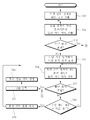
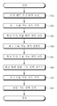
도 1은 본 발명에 따른 차량형 이동 로봇의 충돌 회피 경로 생성 방법을 설명하기 위한 도면이다. 1 is a view for explaining a collision avoidance path generation method of a vehicle-type mobile robot according to the present invention.
도 1을 참조하여 설명하면, 먼저 지향 단위 장애물 배위 공간이 산출된다(S10). 여기서, 본 발명에 따른 지향 단위 장애물 배위 공간의 산출에는 T.Lozano-Perez의 논문 'Spatial planning: a configuration space approach ( Proc. Int. Conf. Computers, May 1983, vol. 32, pp. 108-120)'에 개시된 배위 공간(Configuration space)의 개념을 적용한다. 보다 구체적으로 설명하면, 차량형 이동 로봇의 배위(Configuration)는 목표 위치에 대한 좌표인 x, y, 그리고 차량형 이동 로봇의 지향 각도 θ로 구성된다. 그리고, 차량형 이동 로봇 및 장애물을 포함하는 모든 배위의 세트가 상기 논문에 정의된 배위 공간을 형성한다.Referring to FIG. 1, first, the directional unit obstacle coordination space is calculated (S10). Here, T.Lozano-Perez's paper 'Spatial planning: a configuration space approach (Proc. Int. Conf. Computers, May 1983, vol. 32, pp. 108-120) is used to calculate the directional unit obstacle coordination space according to the present invention. The concept of configuration space disclosed in ')' is applied. More specifically, the configuration of the vehicle-type mobile robot is composed of x, y, which are coordinates with respect to the target position, and the orientation angle θ of the vehicle-type mobile robot. And, a set of all coordinations, including vehicle-type mobile robots and obstacles, forms the coordination spaces defined in the paper.
그리고, 장애물 배위 공간 CO는 차량형 이동 로봇의 움직임과 겹치는 장애물에 대한 배위 세트가 되며, 지향 단위 장애물 배위 공간은 차량형 이동 로봇의 지향 각도 θ에서의 배위 공간, 즉 CO(θ)가 된다. 또한, 모든 충돌 자유 배위는 충돌 자유 배위 공간(Collision free configuration space) Cfree를 형성하며, 차량형 이동 로봇의 지향 각도 θ에서의 충돌 자유 배위 공간이 Cfree(θ)로 표현될 수 있다.The obstacle coordination space CO becomes a coordination set for obstacles overlapping the movement of the vehicle-type mobile robot, and the direct unit obstacle coordination space is a coordination space at the orientation angle θ of the vehicle-type mobile robot, that is, CO (θ). In addition, all collision free coordination forms a collision free configuration space C free , and the collision free coordination space at the orientation angle θ of the vehicle-type mobile robot can be expressed as C free (θ).
그리고, 차량형 이동 로봇의 위치는 하나의 포인트 q, 즉 (x,y) 좌표 상의 하나의 포인트로 정의되며, 본 발명에서는 차량형 이동 로봇의 위치를 나타내는 포인트 q를 로봇 기준 포인트로 정의한다.The position of the vehicle-type mobile robot is defined as one point q, that is, one point on (x, y) coordinates. In the present invention, the point q indicating the position of the vehicle-type mobile robot is defined as a robot reference point.
한편, 본 발명에 따른 지향 단위 장애물 배위 공간은 기 설정된 지향 각도 변위 단위로 산출된다. 보다 구체적으로 설명하면, 지향 각도 변위를 π/4 단위로 설정하는 경우, 지향 단위 장애물 배위 공간은 0, ±π/4, ±π/2, ±3π/4, 2π 단위로 산출된다. 즉 지향 단위 장애물 배위 공간으로는 CO(0), CO(±π/4), CO(±π/2), CO(±3π/4), CO(2π)가 산출된다.Meanwhile, the directing unit obstacle coordination space according to the present invention is calculated in a preset directing angle displacement unit. More specifically, when setting the directional angular displacement in units of π / 4, the directional unit obstacle coordination space is calculated in units of 0, ± π / 4, ± π / 2, ± 3 π / 4, and 2 π. That is, CO (0), CO (± π / 4), CO (± π / 2), CO (± 3π / 4) and CO (2π) are calculated as the direct unit obstacle coordination space.
여기서, 본 발명에서는 지향 단위 장애물 배위 공간이 차량형 이동 로봇의 외형에 따른 점유 영역과 장애물의 점유 영역 간의 민코프스키 합(Minkowski sum)에 의해 산출되는 것을 예로 한다. 또한, 장애물의 점유 영역은 기 설정된 확장 사이즈로 확장된 상태로 민코프스키 합(Minkowski sum)에 적용됨으로써, 충돌에 대한 안정성을 보장할 수 있다.In the present invention, it is assumed that the direct unit obstacle coordination space is calculated by the Minkowski sum between the occupied area according to the appearance of the vehicle-type mobile robot and the occupied area of the obstacle. In addition, the occupied area of the obstacle is applied to the Minkowski sum in a state of being expanded to a preset extension size, thereby ensuring stability against collisions.
이와 같이, 차량형 이동 로봇의 주행 환경 상의 장애물에 대한 지향 단위 장애물 배위 공간 CO(θ)가 각 지향 각도 변위 단위로 전처리 단계, 즉 후술할 실질적인 후보 경로를 찾는 과정 전인 전처리 단계에서 산출됨으로써, 최종 경로 생성을 위한 전체 계산 비용을 효과적으로 감소시킬 수 있게 된다.As such, the direct unit obstacle coordination space CO (θ) for obstacles in the traveling environment of the vehicle-type mobile robot is calculated in the preprocessing step in each directing angular displacement unit, that is, in the preprocessing step before the process of finding a substantial candidate path to be described later. It is possible to effectively reduce the overall computational cost for path generation.
상기와 같은 방법을 통해 지향 단위 장애물 배위 공간 CO(θ)이 산출되면, 모션 세트에 대한 도달 가능 영역의 산출을 통한 후보 경로의 탐색 과정이 수행된다.When the direct unit obstacle coordination space CO (θ) is calculated through the above method, the candidate path search process is performed by calculating the reachable region for the motion set.
여기서, 본 발명에 따른 모션 세트는 적어도 하나의 직진 모션과 적어도 하나의 회전 모션이 기 설정된 순서로 연속적으로 수행되도록 설정되며, 본 발명에서는 하나의 모션 세트가 직진 모션, 회전 모션, 직진 모션의 순으로 3개의 모션의 순차적인 조합으로 설정되는 것을 예로 한다. 또한, 회전 모션은 차량형 이동 로봇의 최대 조향각으로 회전하도록 설정되는 것을 예로 한다.Herein, the motion set according to the present invention is set such that at least one straight motion and at least one rotational motion are continuously performed in a predetermined order, and in the present invention, one motion set is a sequence of straight motion, rotational motion, and straight motion. For example, it is set to a sequential combination of three motions. In addition, the rotational motion is set to rotate to the maximum steering angle of the vehicle-type mobile robot as an example.
이와 같이, 모션 세트가 직진 모션, 회전 모션, 직진 모션의 순으로 하나의 모션 세트의 모션 패턴으로 설정되고, 회전 모션 또한 차량형 이동 로봇의 최대 조향각으로 회전하도록 설정됨으로써, 경로 탐색에 필요한 계산 비용을 현저히 감소시킬 수 있게 된다.In this way, the motion set is set to the motion pattern of one motion set in the order of straight motion, rotational motion, and straight motion, and the rotational motion is also set to rotate at the maximum steering angle of the vehicle-type mobile robot, so that the calculation cost required for the path search is achieved. Can be significantly reduced.
여기서, 차량형 이동 로봇의 지향 각도 θ가 주어지는 경우, 해당 지향 각도 θ에서의 직진 모션의 도달 가능 영역은 지향 각도 θ에 대한 충돌 자유 배위 공간 Cfree(θ) 내에서의 확장으로 산출 가능하며, 이에 대한 상세한 설명은 후술한다.Here, when the direction angle θ of the vehicle-type mobile robot is given, the reachable area of the straight motion at the direction angle θ can be calculated by expansion in the collision free coordination space C free (θ) with respect to the direction angle θ, Detailed description thereof will be described later.
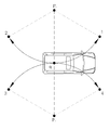
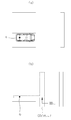
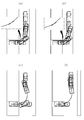
회전 모션은 상술한 바와 같이 최대 조향각 하에서 발생한다. 회전 모션에는 차량형 이동 로봇의 시작 포즈에서의 지향 각도 θstart, 최종 포즈에서의 지향 각도 θfinal, 그리고 회전 방향이 필요하게 된다. 여기서, 회전 모션의 회전 방향은 직진 속도 v와 조향 앵글 φ에 의해 결정될 수 있는데, 상술한 바와 같이, 본 발명에서는 조향 앵글이 최대 조향각으로 설정되어 있으므로, 회전 모션에 대한 입력은, 도 2에 도시된 바와 같이, [v, -v]×[-φmax, φmax]에 의한 4가지 조합 중 하나가 선택 가능하게 된다. 도 2의 1, 2, 3, 4는 회전 모션의 4가지 방향을 나타낸 것이고, Pr는 회전 중심을 나타낸 것이다Rotational motion occurs under maximum steering angle as described above. The rotational motion requires the orientation angle θ start in the starting pose of the vehicle type mobile robot, the orientation angle θ final in the final pose, and the rotation direction. Here, the rotation direction of the rotational motion may be determined by the straight line speed v and the steering angle φ. As described above, in the present invention, since the steering angle is set to the maximum steering angle, the input for the rotational motion is illustrated in FIG. 2. As shown, one of four combinations of [v, -v] x [-? Max,? Max] becomes selectable. 1, 2, 3, and 4 in FIG. 2 represent four directions of rotational motion, and Pr represents a rotational center.
본 발명에서는 충돌 체크를 위한 효과적인 알고리즘의 확정을 위해, 차량형 이동 로봇의 모션에 대해 스웹트 영역(swept area)을 고려하여 장애물의 경계를 확장하는 것을 예로 한다. 이와 같은 장애물 경계의 확장은 차량형 이동 로봇의 회전 모션에 유용하다.In the present invention, in order to determine an effective algorithm for collision check, it is assumed that the boundary of the obstacle is extended in consideration of the swept area for the motion of the vehicle-type mobile robot. This expansion of the obstacle boundary is useful for the rotational motion of the vehicle type mobile robot.
이와 관련하여, 상기 논문에서는 슬라이스 프로젝션(Slice projection) 기법에 대해 개시하고 있는데, 스웹트 영역의 다각형적 근사화(Polygonal approximation)를 적용하고 있다. 따라서, 최종적인 성능은 근사 기법, 로봇의 형태, 환경적인 지형에 영향을 받게 되는데, 본 발명에서는 다각형적 근사화의 가정없이 지향 단위 장애물 배위 공간 CO(θ)의 간단한 연속을 이용함으로써, 보편성(generality)을 보장한다.In this regard, the paper discloses a slice projection technique, which applies a polygonal approximation of the swept region. Therefore, the final performance is affected by the approximation technique, the shape of the robot, and the environmental topography. In the present invention, generality is achieved by using a simple continuation of the direct unit obstacle coordination space CO (θ) without the assumption of polygonal approximation. To ensure.
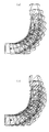
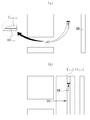
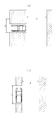
도 3 및 도 4를 참조하여 회전 모션에 대해 보다 구체적으로 설명하면, 도 3은 차량형 이동 로봇이 초기 위치의 지향 방향 0°에서 최종 위치의 지향 방향 π/2로 회전 이동할 때의 회전 모션을 도시한 도면이다. 도 3의 (a)는 차량형 이동 로봇의 회전 모션을 연속적으로 도시한 도면이고, 도 3의 (b)는 회전 모션의 연속에 따라 나타나는 스웹트 영역을 45° 빗금으로 나타낸 도면이다.Referring to FIGS. 3 and 4, the rotational motion will be described in more detail. FIG. 3 illustrates the rotational motion when the vehicle-type mobile robot rotates from the initial direction of 0 ° to the final direction of π / 2. Figure is shown. FIG. 3A is a view showing rotational motion of the vehicle-type mobile robot continuously, and FIG. 3B is a view showing 45 ° hatched swept regions appearing along the continuous rotational motion.
그리고, 도 4는 도 3에 도시된 바와 같은 회전 모션에서 장애물에 대한 회전 모션 장애물 배위 영역 COrot의 산출 과정을 설명하기 위한 도면이다. 도 4를 참조하여 설명하면, 도 4의 (a), (b), (c)는 각각 차량형 이동 로봇의 지향 각도 θ가 0, π/4, π/2일 때의 장애물에 대한 지향 단위 장애물 배위 영역 CO(θ)를 도시하고 있다.4 is a view for explaining a process of calculating a rotation motion obstacle coordination area CO rot for an obstacle in a rotation motion as shown in FIG. 3. Referring to FIG. 4, (a), (b) and (c) of FIG. 4 are orientation units for obstacles when the orientation angles θ of the vehicle-type mobile robot are 0, π / 4, and π / 2, respectively. The obstacle coordination area CO (θ) is shown.
즉, 회전 모션 장애물 배위 영역 COrot의 산출을 위해 회전 모션의 각 궤적 포즈에 대한 지향 단위 장애물 배위 영역이 사용되며, 도 4의 (d)에 도시된 바와 같이, 각 궤적 포즈에 대한 지향 단위 장애물 배위 영역을 모션 기준 포인트 Pm을 중심으로 합하여 회전 모션 장애물 배위 영역 COrot을 산출하게 된다. 여기서, 지향 단위 장애물 배위 영역은 전처리 과정에서 산출되어 있음은 상술한 바와 같다.That is, the orientation unit obstacle coordination region for each trajectory pose of the rotation motion is used to calculate the rotation motion obstacle coordination region CO rot , and as shown in FIG. 4D, the orientation unit obstacle for each trajectory pose The coordination area is summed around the motion reference point Pm to calculate the rotational motion obstacle coordination area COrot . Here, the direct unit obstacle coordination region is calculated in the preprocessing process as described above.
이와 같이 회전 모션에 대한 회전 모션 장애물 배위 영역 COrot를 산출하는 과정을 정리하면, 먼저, 회전 모션의 회전 각도가 입력되는 경우 입력된 회전 각도에 기초하여 회전 모션의 궤적이 산출된다. 이 때, 회전 모션의 궤적은 회전 모션의 궤적 내에서의 궤적 포즈가 지향 각도 변위 단위로 산출된다. 즉, 상술한 바와 같이, 지향 각도 변위를 π/4로 설정하고, 회전 모션의 회전 각도가 0 -> π/2로 90° 회전하는 것으로 가정하는 경우, 궤적 포즈는 0, π/4, π/2로 결정된다.According to this clean up process for calculating the motion rotation obstacle coordinated CO rot area for the rotating motion, first, when the rotation angle of the rotary motion to be input based on the input rotation angle it is calculated in the trajectory of the rotating motion. At this time, the trajectory of the rotational motion is calculated by the trajectory pose in the trajectory of the rotational motion in the direction of the angular displacement. That is, as described above, assuming that the directional angular displacement is set to π / 4 and that the rotational angle of the rotational motion is rotated 90 ° from 0-> π / 2, the trajectory pose is 0, π / 4, π Is determined by / 2.
그리고, 전처리 단계에서 미리 산출된 각 궤적 포즈에서의 차량형 이동 로봇의 지향 각도에 대응하는 지향 단위 장애물 배위 공간, 즉 도 4의 (a), (b) 및 (c)에 도시된 바와 같은 지향 단위 장애물 배위 공간이, 모션 기준 포인트 Pm과 각 궤적 포즈에서의 로봇 기준 포인트 qr 간의 위치 편차에 따라 쉬프트된다.In addition, the orientation unit obstacle coordination space corresponding to the orientation angle of the vehicle-type mobile robot in each trajectory pose calculated in advance in the preprocessing step, that is, orientation as shown in FIGS. 4A, 4B, and 4C. The unit obstacle coordination space is shifted according to the positional deviation between the motion reference point Pm and the robot reference point qr in each trajectory pose.
여기서, 모션 기준 포인트 Pm은 회전 모션의 모션 초기 위치에서의 차량형 이동 로봇의 로봇 기준 포인트 qr로 설정되는 것을 일예로 한다. 도 4의 (d)가 모션 기준 포인트 Pm을 기준으로 각 지향 단위 장애물 배위 공간이 쉬프트된 도면을 도시하는 것은 상술한 바와 같다.Here, for example, the motion reference point Pm is set to the robot reference point qr of the vehicle-type mobile robot at the motion initial position of the rotational motion. FIG. 4 (d) shows a diagram in which each direction unit obstacle coordination space is shifted based on the motion reference point Pm, as described above.
그런 다음, 각 궤적 포즈에 대해 산출된 쉬프트된 지향 단위 장애물 배위 공간의 결합에 따라 해당 회전 모션에 대한 회전 모션 장애물 배위 영역인 Corot가 산출된다. 여기서, 회전 모션 장애물 배위 영역 외부에 차량형 이동 로봇의 로봇 기준 포인트 qr이 위치하는 경우, 해당 회전 모션은 충돌 자유가 된다.Then, the rotational motion of the obstacle region coordination Co rot for the rotating motion, depending on the combination of the shift-oriented coordination unit obstacle space calculated for each pose trajectory is calculated. Here, when the robot reference point qr of the vehicle-type mobile robot is located outside the rotational motion obstacle coordination region, the rotational motion becomes collision free.
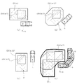
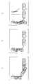
이하에서는 하나의 모션 세트에 대한 도달 가능 영역을 산출하는 방법을 도 5를 참조하여 설명한다. 여기서, 하나의 모션 세트는 직진 모션 -> 회전 모션 -> 직진 모션이 순차적으로 연결되어 구성되는 것은 상술한 바와 같다. Hereinafter, a method of calculating a reachable region for one motion set will be described with reference to FIG. 5. Here, one motion set is configured as the linear motion-> rotational motion-> straight motion is sequentially connected as described above.
먼저, 차량형 이동 로봇의 모션 세트 초기 위치가 설정된다(S61). 여기서, 모션 세트 초기 위치는 해당 모션 세트의 초기 위치에서의 차량형 이동 로봇의 지향 방향인 모션 초기 지향 각도 θprev를 포함한다. 또한, 하나의 모션 세트에 대한 도달 가능 영역의 산출을 위해 해당 모션 세트의 회전 모션에 따른 회전 후의 지향 방향 θi가 요구된다.First, the motion set initial position of the vehicle type mobile robot is set (S61). Here, the motion set initial position includes a motion initial orientation angle θ prev which is a direction of the vehicular mobile robot at the initial position of the motion set. In addition, in order to calculate the reachable area for one motion set, the directing direction θ i after rotation according to the rotational motion of the motion set is required.
이와 같이 차량형 이동 로봇의 모션 세트 초기 위치가 설정되면, 모션 세트 초기 위치에서의 모션 초기 지향 각도 θprev에 대응하는 지향 단위 장애물 배위 공간 CO(θ)에 기초하여 모션 세트를 구성하는 첫 번째 직진 모션에 대한 제1 도달 가능 영역 RRi,1이 산출된다(S62).When the motion set initial position of the vehicle-type mobile robot is set as described above, the first straight line constituting the motion set based on the direct unit obstacle coordination space CO (θ) corresponding to the motion initial orientation angle θ prev at the motion set initial position is obtained. The first reachable region RR i, 1 for the motion is calculated (S62).
도 6의 (a)는 차량형 이동 로봇이 모션 세트 초기 위치에 위치하는 상태를 나타내며, 로봇 기준 포인트가 차량형 이동 로봇의 후륜의 중심으로 설정된 상태를 도시하고 있다.FIG. 6A illustrates a state in which the vehicular mobile robot is positioned at the initial position of the motion set, and shows a state in which the robot reference point is set as the center of the rear wheel of the vehicular mobile robot.
여기서, 도 6의 (b)는 제1 도달 가능 영역을 도시한 도면이다. 도 6의 (b)에 도시된 바와 같이, 직진 모션에 대한 제1 도달 가능 영역은 모션 초기 지행 각도 θprev(도 6의 (a) 및 (b)에서는 0이다)에 대한 충돌 자유 배위 영역 CO(θprev) 내에서 모션 초기 지행 각도 θprev 방향으로의 확장임을 확인할 수 있다. 도 6의 (b) 영역에서 충돌 자유 배위 영역 CO(θprev)는 점선으로 표시되어 있다.6B is a view showing the first reachable region. As shown in FIG. 6B, the first reachable region for the straight motion is the collision free coordination region CO for the motion initial running angle θ prev (which is 0 in FIGS. 6A and 6B). In (θ prev ), it can be confirmed that the motion is in the initial traveling angle in the θ prev direction. In region (b) of FIG. 6, the collision free coordination region CO (θ prev ) is indicated by a dotted line.
첫 번째 직진 모션에 대한 제1 도달 가능 영역이 산출되면, 모션 세트를 구성하는 회전 모션의 회전 각도에 대한 회전 모션 충돌 자유 배위 영역이 산출된다(S63). 여기서, 회전 모션 충돌 자유 배위 영역은 적어도 하나의 지향 단위 장애물 배위 공간에 기초하여 산출된다. 즉, 상술한 바와 같이, 회전 모션 장애물 배위 영역 COrot가 산출되면, 해당 회전 모션에 대한 회전 모션 충돌 자유 배위 영역인 Cfree.rot이 가능하게 된다.When the first reachable region for the first straight motion is calculated, the rotational motion collision free coordination region with respect to the rotational angle of the rotational motion constituting the motion set is calculated (S63). Here, the rotational motion collision free coordination region is calculated based on at least one directing unit obstacle coordination space. That is, as described above, when the rotational motion obstacle coordination area CO rot is calculated, C free.rot, which is the rotational motion collision free coordination area for the rotational motion, becomes possible.
그런 다음, 기 설정된 모션 기준 포인트 Pm와, 회전 모션에서의 차량형 이동 로봇의 회전 초기 위치에서의 차량형 이동 로봇의 로봇 기준 포인트 qr 간의 위치 편차에 따라 제1 도달 가능 영역이 쉬프트된다(S64).Then, the first reachable area is shifted according to the positional deviation between the preset motion reference point Pm and the robot reference point qr of the vehicle-type mobile robot in the initial position of rotation of the vehicle-type mobile robot in the rotational motion (S64). .
여기서, 본 발명에서는 모션 기준 포인트 Pm이 해당 회전 모션의 초기 위치에서의 로봇 기준 포인트 qr로 설정되므로, 직진 모션에 대한 제1 도달 가능 영역에서는 쉬프트가 발생하지 않게 된다. 그러나, 모션 기준 포인트가 회전 모션의 회전 중심으로 설정되는 경우, 직전 모션에 대한 제1 도달 가능 영역이 S64 단계에서 쉬프트가 발생할 수 있음은 물론이다.Here, in the present invention, since the motion reference point Pm is set to the robot reference point qr at the initial position of the rotational motion, the shift does not occur in the first reachable region for the straight motion. However, when the motion reference point is set as the rotation center of the rotational motion, the first reachable region for the immediately preceding motion may shift in step S64.
한편, 회전 모션 충돌 자유 배위 영역 Cfree.rot과 쉬프트된 제1 도달 가능 영역 간의 교차 영역이 회전 모션 도달 가능 영역 RRi.rot으로 산출된다(S65). 도 7의 (a)에는 회전 모션 충돌 자유 배위 영역 Cfree.rot과 쉬프트된 제1 도달 가능 영역 간의 교차 영역이 회전 모션 도달 가능 영역 RRi.rot으로 산출된 예를 도시하고 있다.On the other hand, the intersection area between the rotation motion collision free coordination region C free.rot and the shifted first reachable region is calculated as the rotation motion reachable region RR i.rot (S65). FIG. 7A shows an example in which the intersection region between the rotation motion collision free coordination region C free.rot and the shifted first reachable region is calculated as the rotation motion reachable region RR i.rot .
그리고, 모션 기준 포인트 Pm과, 회전 모션의 회전 최종 위치에서의 로봇 기준 포인트 qr 간의 위치 편차에 따라 회전 모션 도달 가능 영역이 쉬프트된다(S66). 도 7의 (a)에는 쉬프트된 회전 모션 도달 가능 영역 RRi.2가 도시되어 있다.The rotation motion reachable area is shifted according to the positional deviation between the motion reference point Pm and the robot reference point qr at the rotational final position of the rotation motion (S66). In FIG. 7A, the shifted rotational motion reachable area RR i.2 is shown.
그런 다음, 회전 모션의 회전 최종 위치에서의 차량형 이동 로봇의 모션 최종 지향 각도 θfinal에 대응하는 지향 단위 장애물 배위 공간 CO(θfinal)과, 쉬프트된 회전 모션 도달 가능 영역 RRi.2에 기초하여, 모션 세트를 구성하는 두 번째 직진 모션에 대한 제2 도달 가능 영역 RRi가 산출된다(S67). 도 7의 (b)에 점선으로 표시된 영역이 모션 최종 지향 각도 θfinal에 대한 지향 단위 장애물 배위 공간 CO(θfinal)에 기초하여 산출되는 충돌 자유 배위 공간 Cfree(θfinal)으로, 쉬프트된 회전 모션 도달 가능 영역 RRi.2이 모션 최종 지향 각도 방향으로 충돌 자유 배위 공간 Cfree(θfinal) 내에서 연장되어 제2 도달 가능 영역 RRi이 산출되는 것을 확인할 수 있다.Then, based on the directional unit obstacle coordination space CO (θ final ) corresponding to the motion final orientation angle θ final of the vehicle-type mobile robot at the rotation final position of the rotation motion, and the shifted rotation motion reachable region RR i.2 . Thus, the second reachable region RR i for the second straight motion constituting the motion set is calculated (S67). The area indicated by the dotted line in FIG. 7B is shifted rotation to the collision free coordination space C free (θ final ) calculated based on the direct unit obstacle coordination space CO (θ final ) with respect to the motion final orientation angle θ final . It can be seen that the motion reachable region RR i.2 extends in the collision free coordination space C free (θ final ) in the direction of the motion final directivity angle to yield the second reachable region RR i .
상기와 같은 과정을 통해 산출된 제2 도달 가능 영역 RRi이 해당 모션 세트에 대한 최종적인 도달 가능 영역 RRi으로 설정된다(S68).The second area is reached RR i are calculated through a process as described above is set to reach a final area RR i for that set of motion (S68).
이하에서는, 다시 도 1을 참조하여, 본 발명에 따른 차량형 이동 로봇의 충돌 회피 경로 생성 과정에 대해 상세히 설명한다.Hereinafter, the collision avoidance path generation process of the vehicle type mobile robot according to the present invention will be described in detail with reference to FIG. 1.
먼저, 상술한 바와 같이, 지향 단위 장애물 배위 공간이 각 지향 각도 변위 단위로 산출된다(S10). 그런 다음, 차량형 이동 로봇의 목표 위치로부터 적어도 하나의 모션 세트에 따른 도달 가능 영역이 지향 단위 장애물 배위 공간에 기초하여 산출된다.First, as described above, the directing unit obstacle coordination space is calculated in each directing angle displacement unit (S10). Then, the reachable area according to the at least one motion set from the target position of the vehicular mobile robot is calculated based on the directed unit obstacle coordination space.
보다 구체적으로 설명하면, 목표 위치로부터 하나의 모션 세트의 도달 가능 영역이 산출된다(S11). 여기서, 하나의 모션 세트에 대한 도달 가능 영역의 산출 과정은 상술한 바와 같으며, 이 때 목표 위치가 도달 가능 영역의 산출을 위한 모센 세트 초기 위치로 설정된다.More specifically, the reachable area of one motion set is calculated from the target position (S11). Here, the process of calculating the reachable region for one motion set is as described above, and the target position is set to the initial position of the mossen set for the calculation of the reachable region.
목표 위치로부터 시작된 모션 세트의 도달 가능 영역이 차량형 이동 로봇의 출발 위치를 포함하는지 여부를 판단하고(S12), 도달 가능 영역이 출발 위치를 포함하지 않는 경우 다음 차순의 모션 세트에 대한 도달 가능 영역의 산출 과정이 진행된다.It is determined whether the reachable area of the motion set started from the target position includes the starting position of the vehicle type mobile robot (S12), and if the reachable area does not include the starting position, the reachable area for the next motion set Calculation process is performed.
여기서, 현재 모션 세트의 마지막 직진 모션과 다음 모션 세트의 첫 번째 직진 모션을 일치시킴으로서, 순차적으로 연결된 모션 세트가 경로를 형성 가능하게 된다. 즉, S12 단계에서 도달 가능 영역이 출발 위치를 포함하지 않는 경우, 해당 도달 가능 영역에서 새로운 모션 초기 위치를 결정한다(S13). 그런 다음, 새로운 모션 초기 위치로부터 모션 세트의 도달 가능 영역을 산출한다(S14). 여기서, 새로운 도달 가능 영역의 산출 방법은 상술한 바와 같은 바, 그 상세한 설명은 생략한다.Here, by matching the last straight motion of the current motion set with the first straight motion of the next motion set, the sequentially connected motion sets can form a path. That is, when the reachable region does not include the starting position in step S12, a new motion initial position is determined in the reachable region (S13). Then, the reachable area of the motion set is calculated from the new motion initial position (S14). Here, the calculation method of the new reachable region is as described above, and the detailed description thereof is omitted.
이와 같이, 새로운 도달 가능 영역이 산출되면, 동일하게 해당 도달 가능 영역이 출발 위치를 포함하는지 여부를 판단하다(S15). 상술한 S12 단계와 S15 단계에서 도달 가능 영역이 출발 위치를 포함하는 경우, 해당 도달 가능 영역을 출발 허용 영역(ASR)으로 설정한다(S17). 그리고, 출발 허용 영역에 대응하는 모션 세트를 포함하는 하나 또는 연속된 모션 세트의 조합에 기초한 역전파를 통해 출발 위치로부터 목표 위치로 진행 가능한 후보 경로 세트가 생성된다(S18).In this way, when the new reachable area is calculated, it is determined whether the reachable area includes the starting position in the same manner (S15). When the reachable area includes the start position in steps S12 and S15 described above, the reachable area is set as the start allowance area ASR (S17). Then, a candidate path set capable of proceeding from the starting position to the target position is generated through backpropagation based on a combination of one or a series of motion sets including a motion set corresponding to the starting allowable region (S18).
여기서, 후보 경로 세트는 출발 위치로부터 목표 위치로까지의 다수의 후보 경로를 포함하게 되는데, 이는 후보 경로 세트가 다수의 도달 가능 영역의 연결을 통해 생성되어, 도달 가능 영역 내의 포인트의 선택에 따라 하나의 후보 경로 세트에서 다수의 후보 경로가 생성 가능하기 때문이다.Here, the candidate path set includes a plurality of candidate paths from the starting position to the target position, wherein the candidate path set is generated through the concatenation of the plurality of reachable regions, one according to the selection of points in the reachable region. This is because a plurality of candidate paths can be generated from a candidate path set of.
한편, S15 단계에서 도달 가능 영역이 출발 위치를 포함하지 않는 경우, 다음 연속된 모션 세트에 대한 도달 가능 영역의 산출 과정을 진행한다. 여기서, 본 발명에서는 연속된 모션 세트의 개수가 기 설정된 기준 개수에 도달하는 경우, 해당 모센 세트의 조합은 후보 경로 세트의 생성에서 삭제할 수 있다(S16, S17). 즉, 본 발명에 따른 차량형 이동 로봇의 충돌 회피 경로 생성 방법이 주차 보조 시스템에 적용되는 경우, 많은 모션 세트의 조합에 따라 생성되는 후보 경로 세트는 해당 후보 경로 세트의 계산 비용도 많이 소요될 뿐 만 아니라, 생성된 후보 경로 세트 또한 경로 자체가 복잡해지므로, 이와 같은 불필요한 계산의 발생을 제거할 수 있게 된다.On the other hand, if the reachable region does not include the starting position in step S15, the process of calculating the reachable region for the next continuous motion set is performed. Here, in the present invention, when the number of consecutive motion sets reaches a preset reference number, the combination of the corresponding mossen sets may be deleted from generation of candidate path sets (S16 and S17). That is, when the collision avoidance path generation method of the vehicular mobile robot according to the present invention is applied to the parking assistance system, the candidate path set generated according to the combination of many motion sets only requires a large calculation cost of the candidate path set. In addition, the generated set of candidate paths also complicates the path itself, thereby eliminating unnecessary calculations.
여기서, S19 단계와 같이 진행 중인 모션 세트 조합이 삭제되는 경우, 또는 S18 단계와 같이 후보 경로 세트가 생성되는 경우, 다시 목표 위치로부터 도달 가능 영역의 산출 과정을 진행하게 된다.In this case, when the ongoing motion set combination is deleted in step S19, or when the candidate path set is generated in step S18, the process of calculating the reachable region from the target position is performed again.
한편, S16 단계에서 모션 세트의 개수가 기준 개수 이내이면, 현재 도달 가능 영역으로부터 다시 S13 내지 S19 단계를 수행함으로써 후보 경로 세트를 생성하게 된다.Meanwhile, if the number of motion sets is less than the reference number in step S16, the candidate path set is generated by performing steps S13 to S19 again from the current reachable region.
상기와 같은 과정을 통해, 다수의 후보 경로 세트가 생성되면, 생성된 후보 경로 세트 내의 다수의 후보 경로 중 어느 하나가 선택되어 최종 경로가 생성된다. 여기서, 본 발명에 따른 차량형 이동 로봇의 충돌 회피 경로 생성 방법에서는, 각 후보 경로부터 복수의 경로 결정값을 추출한다.Through the above process, when a plurality of candidate path sets are generated, any one of the plurality of candidate paths in the generated candidate path set is selected to generate a final path. Here, in the collision avoidance path generation method of the vehicle-type mobile robot according to the present invention, a plurality of path determination values are extracted from each candidate mirror.
그리고, 각 경로 결정값과, 각 경로 결정값에 대해 할당된 가중치에 기초하여, 각 후보 경로에 대한 경로 비용을 산출하고, 산출된 경로 비용에 기초하여 최종 경로를 결정하는 것을 예로 한다.The path cost for each candidate path is calculated based on each path determination value and the weights assigned to each path determination value, and the final path is determined based on the calculated path cost.
여기서, 본 발명에 따른 경로 결정값은 후보 경로 내에서 차량형 이동 로봇과 장애물 간의 최소 간격, 후보 경로 상에서의 차량형 이동 로봇의 조향의 변경 횟수, 후보 경로 상에서의 전진과 후진 간의 방향 전환 횟수, 그리고, 후보 경로에서의 차량형 이동 로봇의 움직임 거리 중 적어도 2 이상을 포함할 수 있다.Here, the path determination value according to the present invention is the minimum distance between the vehicle-type mobile robot and the obstacle in the candidate path, the number of changes in the steering of the vehicle-type mobile robot on the candidate path, the number of times the direction change between the forward and backward on the candidate path, And, it may include at least two or more of the movement distance of the vehicle-type mobile robot in the candidate path.
이와 같은 경로 비용의 산출은 [수학식 1]과 같이 표현될 수 있다.The calculation of such a path cost may be expressed as shown in [Equation 1].
[수학식 1][Equation 1]
Ctotal = α/Dmin + βNstr + γNmnvr + δDtrvl C total = α / D min + βN str + γN mnvr + δD trvl
여기서, Ctotal은 경로 비용이고, Dmin은 차량형 이동 로봇과 장애물 간의 최소 간격이고, NNstr은 차량형 이동 로봇의 조향 변경 회수이고, NNmnvr은 전진과 후진 간의 방향 전환 회수이고, Dtrvl은 차량형 이동 로봇의 움직임 거리이고, α, β, γ 및 δ는 각각 이들의 가중치이다.Where C total is the path cost, D min is the minimum distance between the vehicle-moving robot and the obstacle, N Nstr is the number of steering changes in the vehicle-moving robot, N Nmnvr is the number of turns between the forward and reverse directions, and D trvl Are the moving distances of the vehicle-type mobile robot, and α, β, γ, and δ are their weights, respectively.
차량형 이동 로봇과 장애물 간의 충돌 가능성은 차량형 이동 로봇이 장애물에 접근할 때 증가하므로, 주행 경로의 안정성을 Dmin으로 정의될 수 있다. Nstrr 및 Nmnvr은 차량형 이동 로봇의 움직임의 량을 나타내며, 유사하게 짧은 주행 거리, 즉 주행 거리 상의 최적성은 Dtrvl로 정의된다.Since the possibility of collision between the vehicle-type mobile robot and the obstacle increases as the vehicle-type mobile robot approaches the obstacle, the stability of the driving path may be defined as D min . N str r and N mnvr represent the amount of movement of the vehicular mobile robot, and similarly, the short traveling distance, that is, the optimum on the traveling distance, is defined as D trvl .
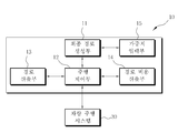
이하에서는 상술한 차량형 이동 로봇의 충돌 회피 경로 생성 방법이 적용된 주차 보조 시스템(10)에 대해 상세히 설명한다.Hereinafter, the
본 발명에 따른 주차 보조 시스템(10)은 차량에 설치되어 차량의 자동 주차를 보조한다. 본 발명에 따른 주차 보조 시스템(10)은, 도 8에 도시된 바와 같이, 최종 경로 생성부(11) 및 주행 제어부(12)를 포함한다.
최종 경로 생성부(11)는 본 발명에 따른 차량형 이동 로봇의 충돌 회피 경로 생성 방법에 따라 최종 경로를 생성한다. 즉, 최종 경로 생성부(11)는 차량의 주차 공간과 관련된 환경 지도 상에서 초기 위치와 목표 위치가 주어지는 경우, 상술한 바와 같은 충돌 회피 경로 생성 방법에 따라 다수의 후보 경로를 생성하고, 생성된 후보 경로 중 어느 하나를 최종 경로로 생성한다.The final
그리고, 주행 제어부(12)는 최종 경로 생성부(11)에 의해 생성된 최종 경로에 따라 차량이 주행되도록, 차량 주행 시스템(30), 예를 들어, EPS(Electric Power Steering)나 엔진 제어 시스템 등을 제어하게 된다.In addition, the driving
여기서, 본 발명에 따른 주차 보조 시스템(10)은 본 발명에 따른 차량형 이동 로봇의 충돌 회피 경로 생성 방법에 따라 생성된 다수의 후보 경로 중 어느 하나를 선택하기 위한 경로 선택부(13)를 포함할 수 있다. 예를 들어, 주행 제어부(12)는 최종 경로 생성부(11)가 차량형 이동 로봇의 충돌 회피 경로 생성 방법에 따라 다수의 후보 경로를 생성하는 경우, 이를 차량에 설치된 디스플레이부(미도시)를 통해 운전자에게 제공할 수 있다.Here, the
그리고, 주행 제어부(12)는, 운전자가 디스플레이부를 통해 제공된 다수의 후보 경로 중 어느 하나를 경로 선택부(13)를 통해 선택하는 경우, 경로 선택부(13)를 통해 선택된 후보 경로가 최종 경로로 생성되도록 최종 경로 생성부(11)를 제어할 수 있다.In addition, when the driver selects any one of a plurality of candidate paths provided through the display unit through the
또한, 본 발명에 따른 주차 보조 시스템(10)은 최종 경로 생성부(11)에 의해 생성된 다수의 후보 경로에 대한 경로 비용을 산출하는 경로 비용 산출부(14)를 포함할 수 있다. 여기서, 경로 비용 산출부(14)는 상술한 [수학식 1]을 통해 산출되는 것을 예로 한다.In addition, the
보다 구체적으로 설명하면, 경로 비용 산출부(14)는 각 후보 경로로부터 복수의 경로 결정값을 추출한다. 그리고, 경로 비용 산출부(14)는 추출된 각 경로 결정값과, 각 경로 결정값에 대해 할당된 가중치에 기초하여, 각 후보 경로에 대한 경로 비용을 산출하게 된다.More specifically, the path cost
이 때, 최종 경로 생성부(11)는 각 후보 경로에 대해 산출된 경로 비용에 기초하여, 최종 경로를 선택할 수 있다. 예를 들어, 최종 경로 생성부(11)는 각 후보 경로에 대해 산출된 경로 비용이 최소인 후보 경로를 최종 경로로 선택할 수 있다. 여기서, 경로 결정값은 상술한 바와 같이, 장애물과의 최소 간격, 조향의 변경 횟수, 전진과 후빈 간의 방향 전환 횟수, 움직인 거리를 포함할 수 있다.At this time, the final
또한, 본 발명에 따른 주차 보조 시스템(10)은, 도 8에 도시된 바와 같이, 각 경로 결정값에 대한 가중치의 입력을 위한 가중치 입력부(15)를 포함할 수 있다. 이를 통해 사용자는 경로 비용의 산출에 적용되는 경로 결정값에 할당되는 가중치를 가중치 입력부(15)를 통해 직접 입력함으로써, 경로 비용의 산출에 적용되는 경로 결정값의 비중을 직접 결정할 수 있게 된다.In addition, the
이하에서는 차량의 주차 보조를 위한 경로 생성, 즉 주차 보조 시스템(10)에 적용되었을 때, 본 발명에 따른 차량형 이동 로봇의 충돌 회피 경로 생성 방법이 제공하는 효과를 시뮬레이션을 통해 얻은 실험 결과에 기초하여 상세히 설명한다.Hereinafter, the path generation for parking assistance of the vehicle, that is, when applied to the
시뮬레이션에 적용된 차량의 파라미터는 상용의 중간 사이즈의 차량이 적용되었다. 즉, 길이 및 폭이 각각 4895mm와 1850mm인 차량을 기준으로 시뮬레이션이 진행되었다. 또한, 시뮬레이션은 도 9의 (a)에 도시된 바와 같은 공간 주차와, 도 9의 (b)에 도시된 바와 같은 평행 주차 두 가지 경우에 대해 모두 진행되었다. 그리고, [수학식 1]에서와 같이 경로 비용의 산출을 통해 최종 경로를 선택하였으며, 가중치의 영향을 판단하기 위해 3개의 다른 가중치 세트에 대해 최종 경로의 선택이 진행되었다.The vehicle parameter used in the simulation was a commercially available medium sized vehicle. That is, the simulation was performed based on the vehicles having lengths and widths of 4895 mm and 1850 mm, respectively. In addition, the simulation was performed for both cases of space parking as shown in Fig. 9A and parallel parking as shown in Fig. 9B. And, as shown in [Equation 1], the final path was selected by calculating the path cost, and the final path was selected for three different weight sets to determine the influence of the weight.
먼저, 도 9의 (a)에 도시된 바와 같은 공간 주차 시뮬레이션이 진행되었으며, 공간 주차 시뮬레이션에 적용된 파라미터로는 지향 각도 변위 θ=10°, 모션 세트 개수의 상한인 기준 개수 nmax = 3, 그리고 도 9의 (a)에 도시된 주차 환경 변수는 각각 a = 7m, b = 2.3m로 설정된다.First, a space parking simulation as shown in FIG. 9 (a) was performed. As a parameter applied to the space parking simulation, a direction angle displacement θ = 10 °, a reference number n max = 3, which is the upper limit of the number of motion sets, and Parking environment variables shown in (a) of FIG. 9 are set to a = 7m and b = 2.3m, respectively.
그리고, 3가지의 가중치 세트는 [표 1]에 나타난 바와 같으며, 각 가중치 세트에 대한 시뮬레이션을 통해 얻어진 최종 경로는 도 10에 도시된 바와 같다. 도 10 (a)는 [표 1]의 가중치 세트 1을 통해 얻어진 최종 경로에 따라 차량이 주행하는 궤적을 도시한 도면이고, 도 10 (b)는 [표 1]의 가중치 세트 2를 통해 얻어진 최종 경로에 따라 차량이 주행하는 궤적을 도시한 도면이고, 도 10 (c)는 [표 1]의 가중치 세트 3을 통해 얻어진 최종 경로에 따라 차량이 주행하는 궤적을 도시한 도면이다.The three weight sets are shown in [Table 1], and the final path obtained through the simulation for each weight set is shown in FIG. 10. FIG. 10 (a) is a diagram illustrating a trajectory of a vehicle traveling along a final path obtained through the weight set 1 of [Table 1], and FIG. 10 (b) is a final obtained through the weight set 2 of [Table 1]. FIG. 10 is a diagram illustrating a trajectory of the vehicle traveling along a route, and FIG. 10 (c) illustrates a trajectory of the vehicle traveling along the final route obtained through the weight set 3 of [Table 1].
[표 1][Table 1]

가중치 세트 1에서의 가중치의 목적은 가장 안전한 경로를 찾는데 있다. 가중치 세트 1에서 α는 [수학식 1]에서 차량과 장애물 간의 최소 간격에 대한 가중치임은 상술한 바와 같으며, 따라서 가중치 세트 1에서의 α 값이 다른 가중치 세트보다 크다.The purpose of weights in weight set 1 is to find the safest path. In the weight set 1, α is the weight of the minimum distance between the vehicle and the obstacle in
[표 2]는 도 10에 도시된 각 가중치 세트에 대한 최종 경로에서 얻어진 경로 결정값들을 나타내고 있다. [표 2]에 나타난 바와 같이, 가중치 세트 1에 대한 최종 경로에서 장애물과의 최소 간격은 Dmin = 235mm이나, 도 10의 (a) 및 [표 2]에 나타낸 바와 같이, 전진과 후진 간의 전환 회수 Nmnvr이 2회 발생함을 알 수 있다.Table 2 shows the path determination values obtained in the final path for each weight set shown in FIG. As shown in Table 2, the minimum distance to the obstacle in the final path for weight set 1 is D min = 235 mm, but as shown in FIGS. 10A and 10, the transition between forward and backward It can be seen that the number N mnvr occurs twice.
[표 2]TABLE 2

만약, 운전자가 전진과 후진 간의 전환 회수 Nmnvr의 최소화를 요구하는 경우, γ를 증가시키면 가능하게 된다. 가중치 세트 2는 γ가 다른 가중치 세트보다 크게 설정되었다. 도 10의 (b)에 도시된 바와 같이, 가중치 세트 2에 대한 최종 경로는 전진과 후진 간의 전환이 발생하지 않는다.If the driver requires minimizing the number of transitions N mnvr between forward and reverse, increasing γ is possible. Weight set 2 is set such that γ is larger than other weight sets. As shown in FIG. 10B, the final path for weight set 2 does not cause a transition between forward and backward.
여기서, 가중치 세트 2에 대한 최종 경로에서의 장애물과의 최소 간격 Dmin은 129.1로 가중치 세트 1에 대한 최종 경로에서의 Dmin 값보다 짧음을 알 수 있다. 이는 가중치 세트 2에 대한 최종 경로의 제어 효과가 가중치 1보다는 높은 반면, 충돌 위험은 가중치 세트 1에 대한 최종 경로보다 높음을 의미한다. 따라서, 미끄러운 바닥이나 부정확한 센서 등과 같이 높은 불확실한 컨데션에서 충돌 회피를 위한 경로 선택에서는 가중치 세트 1의 사용이 바람직할 수 있다.Here, it can be seen that the minimum distance D min from the obstacle in the final path for the weight set 2 is 129.1, which is shorter than the value of D min in the final path for the weight set 1. This means that the control effect of the final path for weight set 2 is higher than
가장 짧은 움직임 거리는 통상적인 경로 계획에서 가장 일반적인 성능 측정 방법 중 하나이다. 도 10의 (c)는 가중치 세트 3에 따른 최종 경로로 가장 짧은 경로를 나타내고 있다. 가중치 세트 3의 δ가 다른 가중치 세트보다 크게 설정되었음을 알 수 있다.The shortest movement distance is one of the most common performance measurement methods in conventional path planning. FIG. 10C shows the shortest path as the final path according to the weight set 3. FIG. It can be seen that δ of weight set 3 is set larger than other weight sets.
[표 2]에 나타난 바와 같이, 가중치 세트 1 및 2에 대한 최종 경로에서의 움직임 거리 Dtrvl은 각각 20.4m, 16.7일 때. 가중치 세트 3에 대한 최종 경로의 움직임 거리 Dtrvl은 16.0m로 나타났다.As shown in Table 2, the movement distance D trvl in the final path for the weight sets 1 and 2 is 20.4 m and 16.7, respectively. The distance D trvl of the final path for the weight set 3 is 16.0 m .
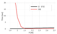
이하에서는 도 11을 참조하여 평행 주차 시뮬레이션에 대해 설명한다. 통상적으로 평행 주차는 적어도 2개의 회전 모션을 포함하기 때문에 경로가 공간 주차보다는 복잡하다. 여기서, 시뮬레이션에서는 도 9의 (b)의 주차 환경에서 파라미터 a = 0.7m, b = 2.3m로 설정하여 진행되었다. 그리고, 시뮬레이션에 적용되는 다른 파라미터, 즉, 차량 사이즈, 지향 각도 변위, 기준 개수는 상술한 공간 주차 시뮬레이션과 동일하게 적용하였으며, 가중치 세트 또한 [표 1]을 사용한다.Hereinafter, a parallel parking simulation will be described with reference to FIG. 11. Since parallel parking typically involves at least two rotational motions, the path is more complex than space parking. Here, the simulation was performed by setting the parameters a = 0.7m and b = 2.3m in the parking environment of FIG. 9 (b). In addition, other parameters applied to the simulation, that is, the vehicle size, the directional angular displacement, and the reference number were applied in the same manner as the above-described space parking simulation, and the weight set is also used in [Table 1].
도 11은 [표 1]에 나타낸 3 가지의 가중치 세트에 대한 시뮬레이션을 통해 얻어진 최종 경로에 따른 주행 결과를 도시한 도면이다. 도 11의 (a)는 [표 1]의 가중치 세트 1을 통해 얻어진 최종 경로에 따라 차량이 주행하는 궤적을 도시한 도면이고, 도 11의 (b)는 [표 1]의 가중치 세트 2를 통해 얻어진 최종 경로에 따라 차량이 주행하는 궤적을 도시한 도면이고, 도 11의 (c)는 [표 1]의 가중치 세트 3을 통해 얻어진 최종 경로에 따라 차량이 주행하는 궤적을 도시한 도면이다. 그리고, [표 3]은 도 11에 도시된 각 가중치 세트에 대한 최종 경로에서 얻어진 경로 결정값들을 나타내고 있다. FIG. 11 is a diagram illustrating driving results along a final path obtained through simulation of three weight sets shown in [Table 1]. FIG. 11A illustrates a trajectory of driving of a vehicle according to the final path obtained through the weight set 1 of Table 1, and FIG. 11B illustrates a weight set 2 of FIG. It is a figure which shows the trajectory which a vehicle runs along the obtained last route, and FIG. 11 (c) is a figure which shows the trajectory which a vehicle runs along the final route obtained through the weight set 3 of [Table 1]. Table 3 shows the path determination values obtained in the final path for each weight set shown in FIG.
[표 3][Table 3]

안전한 경로, 즉 장애물과의 최소 간격이 가장 큰 가중치 세트 1에 대한 최종 경로가 도 11의 (a)에 도시되었으며, 최소 간격 Dmin = 300mm이다. 그리고, 도 11의 (a) 및 [표 3]에 나타난 바와 같이, 전진과 후진 간의 전환 회수가 2회로 나타났다.The safe path, ie the final path for weight set 1 with the largest minimum distance to the obstacle, is shown in Figure 11 (a), with the minimum distance D min = 300 mm. And, as shown in Fig. 11 (a) and [Table 3], the number of times of switching between the forward and backward appeared twice.
가중치 세트 2는 전진과 후진 간의 전환 회수가 최소인 경로를 나타내는 것으로, 도 11의 (b) 및 [표 3]에 나타난 바와 같이, Nmnvr이 0으로 나타났다. 그리고, 가중치 세트 2에 따른 최종 경로에서 장애물과의 최소 간격은 106.2로 가중치 세트 1에 따른 최종 경로보다 매우 작게 나타났다. 가중치 세트 3은 차량의 움직임 거리가 최소인 경로의 탐색에 적용되나, 가중치 세트 2와 큰 차이가 나타나지 않았다.The weight set 2 represents the path with the minimum number of conversions between the forward and the reverse, and as shown in FIG. 11B and Table 3, N mnvr is 0. In addition, the minimum distance from the obstacle in the final path according to the weight set 2 is 106.2, which is much smaller than the final path according to the weight set 1. The weight set 3 is applied to the search for the path with the smallest moving distance of the vehicle, but does not show a big difference from the weight set 2.
상기와 같은 평행 주차에서는 주차 구역의 폭인 b 값이 주차의 어려움을 나타내는 중요한 특징으로 작용한다. b 값이 작은 경우에는 차량의 주차에 있어 더 많은 움직임, 즉 전진과 후진의 방향 전환 횟수를 더 요구하게 된다. 따라서, 과도한 전환 횟수를 피하기 위해 높은 γ값의 선택이 바람직하다.In the parallel parking as described above, the b value, which is the width of the parking area, serves as an important feature indicating the difficulty of parking. Smaller values of b require more movement in the parking of the vehicle, ie the number of turns between forward and reverse. Therefore, selection of high γ values is desirable to avoid excessive number of conversions.
한편, 본 발명에 따른 차량형 이동 로봇의 충돌 회피 경로 생성 방법은 직진 모션과 최대 조향각에 따른 회전 모션으로 구성된 모션 세트만으로 경로가 생성되는 것은 상술한 바와 같다. 이와 같은 기본적인 모션이 심플하더라도 본 발명에 따른 차량형 이동 로봇의 충돌 회피 경로 생성 방법에 의해 경로가 생성되더라도 다양한 모션이 얻어질 수 있다.On the other hand, in the collision avoidance path generation method of the vehicle-type mobile robot according to the present invention as described above, the path is generated only by the motion set consisting of the straight motion and the rotational motion according to the maximum steering angle. Even if the basic motion is simple, various motions may be obtained even when the path is generated by the collision avoidance path generation method of the vehicle-type mobile robot according to the present invention.
여기서, 본 발명에 따른 차량형 이동 로봇의 충돌 회피 경로 생성 방법의 커버리지 영역(Coverage area)은 모든 출발 허용 영역(ASR)의 결합으로, 커버리지 영역(Coverage area)의 크기는 모션 세트의 허용 개수, 즉 상술한 기준 개수의 크기가 증가할수록 커지게 된다. [표 4]는 도달 가능 영역의 계산을 위한 시뮬레이션 조건을 나타낸다.Here, the coverage area of the collision avoidance path generation method of the vehicle-type mobile robot according to the present invention is a combination of all the starting allowance areas ASR, and the size of the coverage area is the allowable number of motion sets, That is, as the size of the above-mentioned reference number increases, it becomes larger. Table 4 shows the simulation conditions for the calculation of the reachable area.
[표 4][Table 4]

도 12는 커버리지 영역의 계산 결과를 도시한 도면이다. 도 12에서 45° 빗금 영역이 도달 가능 영역의 결합인 커버리지 영역을 나타내고 있다. 도 12의 (a)는 기준 개수의 크기가 1인 조건에서의 도달 가능 영역을 나타내고 있다. 커버리지 비율(Coverage ratio)은 전체 충돌 자유 영역에 대한 도달 가능 영역의 비율로 정의된다. 도 12의 (a)에서는 하나의 회전 모션만이 적용되기 때문에 도달 가능 영역이 좁고 커버리지 비율은 22.7%로 나타났다.12 is a diagram illustrating a calculation result of a coverage area. In FIG. 12, the 45 ° hatched area represents a coverage area that is a combination of reachable areas. Fig. 12A shows the reachable area under the condition that the size of the reference number is one. Coverage ratio is defined as the ratio of reachable area to total collision free area. In FIG. 12A, since only one rotational motion is applied, the reachable area is narrow and the coverage ratio is 22.7%.
반면, 2개의 모션 세트가 허용되는 경우, Cfree(θini)의 95.5%가 도 12에 도시된 바와 같이, 도달 가능 영역으로 나타나게 된다. 즉, 도 12의 (b)로부터 대부분의 모든 충돌 자유 영역이 연속된 2개의 모션 세트에 의해 도달 가능 영역이 됨을 확인할 수 있다. 이는 만약 초기 위치가 커버리지 영역에 있는 경우에 차량은 목표 위치로 성공적으로 조향 가능함을 의미한다.On the other hand, if two motion sets are allowed, 95.5% of C free (θ ini ) will appear as reachable regions, as shown in FIG. 12. That is, it can be seen from (b) of FIG. 12 that most of all collision free regions are reachable regions by two consecutive motion sets. This means that if the initial position is in the coverage area the vehicle can successfully steer to the target position.
만약, 도 12의 (c)에 도시된 바와 같이, 연속된 3개의 모션 세트가 허용되는 경우 커버리지 영역이 97.8%가 된다. 반면, 커버리지 영역은 계산 비용이 높아지는 경우, 즉 기준 개수가 증가하는 동안 더 이상 크게 증가하지 않음을 확인할 수 있다. 따라서, 본 발명에 따른 차량형 이동 로봇의 충돌 회피 경로 생성 방법에서는 공간 주차에서 2개의 연속된 모션 세트 만으로도 충분히 효과적인 경로 생성이 가능하다는 점을 확인할 수 있다.As shown in FIG. 12C, the coverage area becomes 97.8% when three consecutive motion sets are allowed. On the other hand, it can be seen that the coverage area no longer increases significantly when the calculation cost increases, that is, while the number of reference points increases. Therefore, in the collision avoidance path generation method of the vehicle-type mobile robot according to the present invention, it can be confirmed that only two consecutive motion sets can be effectively generated in space parking.
도 12의 (d)는 평행 주차에 대한 시뮬레이션 결과를 도시한 도면으로, b가 차량의 길이보다 1.35배 넓은 상태로 이는 상대적으로 좁은 환경을 의미한다. 3개의 연속된 모션 세트를 허용하는 경우, 커버리지 영역이 95.2%로 나타났다. 상술한 바와 같이, 통상적으로 평행 주차에서는 2회 이상의 회전 모션을 요구하기 때문에, 모션 세트의 허용 개수가 3은 상대적으로 작음을 알 수 있다.12 (d) shows a simulation result for parallel parking, in which b is 1.35 times wider than the length of the vehicle, which means a relatively narrow environment. In case of allowing three consecutive motion sets, the coverage area was 95.2%. As described above, since the parallel parking usually requires two or more rotational motions, it can be seen that the allowable number of motion sets is relatively small.
이하에서는 본 발명에 따른 차량형 이동 로봇의 충돌 회피 경로 생성 방법과, 기존의 Probabilistic Roadmap(PRM) 방법을 비교한 시뮬레이션 결과에 대해 설명한다.Hereinafter, a simulation result comparing the collision avoidance path generation method of the vehicle type mobile robot according to the present invention and the conventional Probabilistic Roadmap (PRM) method will be described.
PRM 방법은 계산 효율과 높은 성능 때문에 주차 제어에 적절하다는 점은 상술한 바와 같으며, 실용적으로 유용하며 기존의 경로 생성 방법 중에 가장 최신의 솔루션으로 평가되고 있다.As described above, the PRM method is suitable for parking control because of computational efficiency and high performance. It is practically useful and is evaluated as the latest solution among the existing path generation methods.
비교 시뮬레이션에서는 Kavraki, L. E., Svestka, P., Latombe, J.-C., 및 Overmars의 논문 'Probabilistic Roadmaps for Path Planning in High Dimensional Configuration Spaces(IEEE Trans. on Robotics and Automation, 1996, 12, (4), pp. 566-580)'에 개시된 PRM 계획자를 적용하였다. 상기 논문의 PRM 계획자는 반복을 통해 멀티 경로를 생성한다. 그리고, 최적 경로는 [수학식 1]을 이용한 경로 비용의 산출을 통해 결정하였다.In comparative simulations, see Kavraki, LE, Svestka, P., Latombe, J.-C., and Overmars' Probabilistic Roadmaps for Path Planning in High Dimensional Configuration Spaces (IEEE Trans. On Robotics and Automation, 1996, 12, (4). ), pp. 566-580). The PRM planner in this paper creates multipaths through iteration. The optimal path was determined by calculating the path cost using
비교 시뮬레이션에 대한 파라미터로, 차량의 길이 및 폭은 각각 4895mm와 1850mm, 지향 각도 변위 θ=10°, 모션 세트 개수의 상한인 기준 개수 nmax = 3, 그리고, 공간 주차 환경에서의 주차 환경 변수 a = 5.5m/7.5m, b = 2.3m로 설정된다. 그리고, 가중치는 α=10000, β=1, γ=10, δ=0.0001로 설정하고, 경계 조건으로 목표 위치는 [-0.4,0.0,0]이고, 초기 위치는 [3.5,10.0,90]으로 설정한다.As parameters for the comparison simulation, the length and width of the vehicle are 4895 mm and 1850 mm, the directional angular displacement θ = 10 °, the reference number nmax = 3, which is the upper limit of the number of motion sets, and the parking environment variable a = in the space parking environment. 5.5m / 7.5m, b = 2.3m. The weight is set to α = 10000, β = 1, γ = 10 and δ = 0.0001, the target position is [-0.4,0.0,0] as the boundary condition, and the initial position is [3.5,10.0,90]. Set it.
도 13은 상기와 같은 조건에 따른 시뮬레이션 결과를 도시한 도면이다. 도 13의 (a)는 a= 5.5m인 조건에서 본 발명에 따른 차량형 이동 로봇의 충돌 회피 경로 생성 방법의 시뮬레이션 결과를 도시한 도면이고, 도 13의 (b)는 a= 5.5m인 조건에서 PRM 계획자의 시뮬레이션 결과를 도시한 도면이고, 도 13의 (c)는 a= 7.5m인 조건에서 본 발명에 따른 차량형 이동 로봇의 충돌 회피 경로 생성 방법의 시뮬레이션 결과를 도시한 도면이고, 도 13의 (d)는 a= 7.5m인 조건에서 PRM 계획자의 시뮬레이션 결과를 도시한 도면이다. 그리고, [표 5]는 상기와 같은 비교 시뮬레이션 결과를 나타내고 있다.13 is a diagram showing simulation results according to the above conditions. FIG. 13 (a) is a diagram showing a simulation result of the collision avoidance path generation method of the vehicular mobile robot according to the present invention under the condition of a = 5.5m, and FIG. 13 (b) is a condition where a = 5.5m FIG. 13 (c) is a view showing a simulation result of the collision avoidance path generation method of the vehicle-type mobile robot according to the present invention under the condition of a = 7.5m, FIG. 13 (d) shows a simulation result of the PRM planner under the condition of a = 7.5m. And Table 5 has shown the comparison simulation result as mentioned above.
[표 5]TABLE 5

a가 5.5m일 때, 본 발명에 따른 차량형 이동 로봇의 충돌 회피 경로 생성 방법은 98개의 후보 경로가 생성되었고, 최종 경로의 경로 비용이 117.3으로 나타났다. 반면, PRM 방법은 30개의 후보 경로가 생성되었으며, 최종 경로의 경로 비용은 134.0으로 나타났다.When a is 5.5m, 98 candidate paths were generated in the collision avoidance path generation method of the vehicle-type mobile robot according to the present invention, and the path cost of the final path was 117.3. In contrast, the PRM method generated 30 candidate paths, and the path cost of the final path was 134.0.
계산 시간에 있어서, 본 발명에 따른 차량형 이동 로봇의 충돌 회피 경로 생성 방법의 경우 0.250s이고, PRM 방법은 8.750s로 나타났다. 결과적으로, 본 발명에 따른 차량형 이동 로봇의 충돌 회피 경로 생성 방법이 계산 시간과 최적화의 관점에서 더 효과적임을 확인할 수 있다.In the calculation time, the collision avoidance path generation method of the vehicle type mobile robot according to the present invention is 0.250s, and the PRM method is 8.750s. As a result, it can be confirmed that the collision avoidance path generation method of the vehicle-type mobile robot according to the present invention is more effective in terms of calculation time and optimization.
한편, a=7.5m인 조건에서, 본 발명에 따른 차량형 이동 로봇의 충돌 회피 경로 생성 방법의 경로 비용은 81.2였고, RPM 방법은 95.1로 나타났다. 계산 시간의 경우, 경계 조건이나 주차 환경 등과 같은 몇몇 요소에 의존하게 된다. a=7.5m일 때, PRM 계획자의 계산 시간(0.89s)이 본 발명에 따른 차량형 이동 로봇의 충돌 회피 경로 생성 방법(1.10s)보다 조금 짧게 나타났음을 확인할 수 있다. 그러나, 본 발명에 따른 차량형 이동 로봇의 충돌 회피 경로 생성 방법이 충분히 많은 많은 후보 경로(2292개)를 생성하였기 때문에, PRM 방법보다 더 빠르게 경로를 생성하는 것으로 정의할 수 있다.On the other hand, under the condition of a = 7.5m, the path cost of the collision avoidance path generation method of the vehicle-type mobile robot according to the present invention was 81.2, the RPM method was 95.1. In the case of calculation time, it depends on several factors such as boundary conditions and parking environment. When a = 7.5m, it can be seen that the calculation time (0.89s) of the PRM planner is slightly shorter than the collision avoidance path generation method (1.10s) of the vehicle-type mobile robot according to the present invention. However, since the collision avoidance path generation method of the vehicle-type mobile robot according to the present invention generates a large enough number of candidate paths (2292), it can be defined to generate the path faster than the PRM method.
또한, PRM 방법은 주차 환경이 좁은 통로를 포함할 때, 경로를 찾는데 실패하는 경우가 있음은 잘 알려져 있다. 도 14는 주차 구역의 폭 b를 변경해가며 경로를 찾는데 소요된 시간을 본 발명에 따른 차량형 이동 로봇의 충돌 회피 경로 생성 방법과 PRM 방법에 대해 시뮬레이션한 결과를 나타낸 그래프이다.It is also well known that the PRM method may fail to find a route when the parking environment includes a narrow passage. 14 is a graph showing a simulation result of the collision avoidance path generation method and the PRM method of the vehicle-type mobile robot according to the present invention for the time taken to find the path while changing the width b of the parking area.
도 14의 그래프 상에서 나타낸 시간(y축)은 30번의 시뮬레이션 결과의 평균값을 나타낸다. 도 14의 그래프를 통해 PRM 방법이 b가 작을 때 많은 계산 시간을 소비함을 확인할 수 있다. 여기서, b가 2.1보다 큰 경우 두 방법이 유사한 성능을 나타내고 있으나, b가 2.1보다 작아질 때 PRM 방법의 성능이 급격히 나빠지는 것을 확인할 수 있다. 통상적인 차량의 폭이 1.85m임을 고려할 때, 본 발명에 따른 차량형 이동 로봇의 충돌 회피 경로 생성 방법이 실제 환경에서의 적용성이 보다 높음을 확인할 수 있다.The time (y-axis) shown on the graph of FIG. 14 represents the average value of 30 simulation results. It can be seen from the graph of FIG. 14 that the PRM method consumes a lot of computation time when b is small. Here, when b is greater than 2.1, the two methods show similar performance, but when b is smaller than 2.1, it can be seen that the performance of the PRM method deteriorates rapidly. Considering that the width of the conventional vehicle is 1.85m, it can be confirmed that the collision avoidance path generation method of the vehicle-type mobile robot according to the present invention has higher applicability in the actual environment.
비록 본 발명의 몇몇 실시예들이 도시되고 설명되었지만, 본 발명이 속하는 기술분야의 통상의 지식을 가진 당업자라면 본 발명의 원칙이나 정신에서 벗어나지 않으면서 본 실시예를 변형할 수 있음을 알 수 있을 것이다. 발명의 범위는 첨부된 청구항과 그 균등물에 의해 정해질 것이다.Although several embodiments of the present invention have been shown and described, those skilled in the art will appreciate that various modifications may be made without departing from the principles and spirit of the invention . It is intended that the scope of the invention be defined by the claims appended hereto and their equivalents.
Claims (18)
(a) 기 설정된 지향 각도 변위 단위로 상기 차량형 이동 로봇의 포즈와 장애물이 겹치는 영역에 대한 지향 단위 장애물 배위 공간을 산출하는 단계와;
(b) 상기 차량형 이동 로봇의 목표 위치로부터 적어도 하나의 모션 세트에 따른 도달 가능 영역이 상기 지향 단위 장애물 배위 공간에 기초하여 산출되되, 복수의 상기 모션 세트는 연속된 경로를 형성하도록 연속적으로 연결되며 상기 도달 가능 영역은 상기 각 모션 세트 단위로 산출되는 단계와;
(c) 상기 각 모션 세트의 상기 도달 가능 영역이 상기 차량형 이동 로봇의 출발 위치를 포함하는 경우, 상기 출발 위치를 포함한 상기 도달 가능 영역을 출발 허용 영역으로 설정하는 단계와;
(d) 상기 출발 허용 영역에 대응하는 상기 모션 세트를 포함하는 하나 또는 연속된 상기 모션 세트의 조합에 기초한 역전파를 통해 상기 출발 위치로부터 상기 도착 위치로 적어도 하나의 후보 경로를 갖는 후보 경로 세트가 생성되는 단계와;
(e) 상기 복수의 후보 경로 중 어느 하나가 최종 경로로 생성되는 단계를 포함하는 것을 특징으로 하는 차량형 이동 로봇의 충돌 회피 경로 생성 방법.In the collision avoidance path generation method of a vehicle type mobile robot,
calculating a directing unit obstacle coordination space with respect to a region where the pose and the obstacle of the vehicle-type mobile robot overlap in a preset directing angle displacement unit;
(b) a reachable area according to at least one motion set from a target position of the vehicular mobile robot is calculated based on the direct unit obstacle coordination space, wherein the plurality of motion sets are continuously connected to form a continuous path Calculating the reachable area in units of the respective motion sets;
(c) if the reachable area of each motion set includes a start position of the vehicular mobile robot, setting the reachable area including the start position as a start allowance area;
(d) a candidate path set having at least one candidate path from the starting position to the arrival position via backpropagation based on a combination of one or successive motion sets comprising the motion set corresponding to the starting allowance area; Generated;
(e) generating one of the plurality of candidate paths as the final path;
상기 모션 세트는 적어도 하나의 직진 모션과 적어도 하나의 회전 모션이 기 설정된 순서로 연속적으로 수행되도록 설정되며;
(f) 상기 (b) 단계, 상기 (c) 단계 및 상기 (e) 단계가 상기 회전 모션의 상기 지향 각도 변위와 상기 직진 모션의 직진 거리 중 적어도 하나의 변경에 따라 반복 수행되어 복수의 후보 경로 세트가 생성되는 단계를 더 포함하며;
상기 (e) 단계에서는 상기 복수의 후보 경로 세트를 구성하는 복수의 상기 후보 경로 중 어느 하나가 상기 최종 경로로 결정되는 것을 특징으로 하는 차량형 이동 로봇의 충돌 회피 경로 생성 방법.The method of claim 1,
The motion set is set such that at least one straight motion and at least one rotational motion are performed continuously in a preset order;
(f) the steps (b), (c), and (e) are repeatedly performed according to a change of at least one of the directional angular displacement of the rotational motion and the straight distance of the straight motion to generate a plurality of candidate paths. Further comprising generating a set;
In the step (e), any one of the plurality of candidate paths constituting the plurality of candidate path sets is determined as the final path.
하나의 상기 모션 세트는 직진 모션, 회전 모션, 직진 모션 순으로 설정되는 것을 특징으로 하는 차량형 이동 로봇의 충돌 회피 경로 생성 방법.The method of claim 2,
The motion set of the collision avoidance path of the vehicle-type mobile robot, characterized in that the motion set is set in the order of straight motion, rotational motion, straight motion.
상기 회전 모션은 상기 차량형 이동 로봇의 최대 조향각으로 회전하도록 설정되는 것을 특징으로 하는 차량형 이동 로봇의 충돌 회피 경로 생성 방법.The method of claim 3,
And the rotational motion is set to rotate at the maximum steering angle of the vehicle-type mobile robot.
상기 (a) 단계에서 상기 지향 단위 장애물 배위 공간은 상기 차량형 이동 로봇의 외형에 따른 점유 영역과 상기 장애물의 점유 영역 간의 민코프스키 합(Minkowski sum)에 의해 산출되는 것을 특징으로 하는 차량형 이동 로봇의 충돌 회피 경로 생성 방법.The method of claim 2,
In the step (a), the directional unit obstacle coordination space is calculated by Minkowski sum between the occupied area according to the appearance of the vehicle-type mobile robot and the occupied area of the obstacle. Collision avoidance path generation
상기 (a) 단계에서 상기 장애물의 점유 영역은 기 설정된 확장 사이즈로 확장된 상태로 상기 민코프스키 합(Minkowski sum)에 적용되는 것을 특징으로 하는 차량형 이동 로봇의 충돌 회피 경로 생성 방법.The method of claim 5,
And in the step (a), the occupation area of the obstacle is applied to the Minkowski sum in a state in which the obstacle is occupied in a predetermined extension size.
상기 (b) 단계에서 하나의 상기 모션 세트에 대한 상기 도달 가능 영역은,
(b1) 상기 차량형 이동 로봇의 모션 세트 초기 위치가 설정되는 단계와;
(b2) 상기 모션 세트 초기 위치에서의 상기 차량형 이동 로봇의 모션 초기 지향 각도에 대응하는 상기 지향 단위 장애물 배위 공간에 기초하여 상기 모션 세트를 구성하는 첫 번째 직진 모션에 대한 제1 도달 가능 영역이 산출되는 단계와;
(b3) 상기 모센 세트를 구성하는 회전 모션의 회전 각도에 대한 회전 모션 충돌 자유 배위 영역이 적어도 하나의 상기 지향 단위 장애물 배위 공간에 기초하여 산출되는 단계와;
(b4) 기 설정된 모션 기준 포인트와, 상기 회전 모션에서의 상기 차량형 이동 로봇의 회전 초기 위치에서의 상기 차량형 이동 로봇의 로봇 기준 포인트 간의 위치 편차에 따라 상기 제1 도달 가능 영역이 쉬프트되는 단계와;
(b5) 상기 회전 모션 출동 자유 배위 영역과 상기 쉬프트된 제1 도달 가능 영역 간의 교차 영역이 회전 모션 도달 가능 영역으로 산출되는 단계와;
(b6) 상기 회전 모션의 회전 최종 위치에서의 상기 로봇 기준 포인트와 상기 모션 기준 포인트 간의 위치 편차에 따라 상기 회전 모션 도달 가능 영역이 쉬프트되는 단계와;
(b7) 상기 회전 최종 위치에서의 상기 차량형 이동 로봇의 모션 최종 지향 각도에 대응하는 상기 지향 단위 장애물 배위 공간과 상기 쉬프트된 회전 모션 도달 가능 영역에 기초하여, 상기 모션 세트를 구성하는 두 번째 직진 모션에 대한 제2 도달 가능 영역이 산출되는 단계와;
(b8) 상기 제2 도달 가능 영역이 해당 모션 세트에 대한 상기 도달 가능 영역으로 설정되는 단계의 수행을 통해 산출되는 것을 특징으로 하는 차량형 이동 로봇의 충돌 회피 경로 생성 방법.The method of claim 2,
In the step (b), the reachable area for one motion set is
(b1) setting an initial position of a motion set of the vehicle-type mobile robot;
(b2) there is a first reachable region for the first straight motion constituting the motion set based on the orientation unit obstacle coordination space corresponding to the motion initial orientation angle of the vehicular mobile robot at the motion set initial position; Calculated steps;
(b3) calculating a rotational motion impingement free coordination region with respect to the rotational angle of the rotational motion constituting the mosen set based on at least one directing unit obstacle coordination space;
(b4) shifting the first reachable area according to a position deviation between a preset motion reference point and a robot reference point of the vehicle-type mobile robot at an initial rotational position of the vehicle-type mobile robot in the rotational motion; Wow;
(b5) calculating an intersection region between the rotational motion outgoing free configuration region and the shifted first reachable region as a rotational motion reachable region;
(b6) shifting the rotational motion reachable area according to a positional deviation between the robot reference point and the motion reference point at the final rotational position of the rotational motion;
(b7) a second straight line constituting the motion set based on the directional unit obstacle coordination space and the shifted rotational motion reachable area corresponding to the motion final orientation angle of the vehicular mobile robot at the rotational final position; Calculating a second reachable region for the motion;
(b8) The collision avoidance path generation method of the vehicular mobile robot, characterized in that it is calculated through the step of setting the second reachable area to the reachable area for the corresponding motion set.
상기 (b1) 단계에서는,
상기 목표 위치로부터 상기 모션 세트에 대한 도달 가능 영역의 산출이 시작되는 경우 상기 목표 위치가 상기 모션 세트 초기 위치로 설정되며;
상기 연속된 모션 세트의 조합의 경우, 이전 모션 세트에 대해 산출된 도달 가능 영역 내에서 선택된 하나의 위치가 상기 모션 세트 초기 위치로 설정되는 것을 특징으로 하는 차량형 이동 로봇의 충돌 회피 경로 생성 방법.The method of claim 7, wherein
In the step (b1),
When the calculation of the reachable area for the motion set is started from the target position, the target position is set to the motion set initial position;
In the case of the combination of the continuous motion set, the collision avoidance path generation method of the vehicular mobile robot, characterized in that the selected position within the reachable area calculated for the previous motion set is set as the initial position of the motion set.
상기 (b3) 단계는,
(b31) 상기 회전 모션의 회전 각도에 기초하여 상기 회전 모션의 궤적 내에서의 궤적 포즈가 상기 지향 각도 변위 단위로 산출되는 단계와;
(b32) 상기 각 궤적 포즈에서의 상기 차량형 이동 로봇의 지향 각도에 대응하는 상기 지향 단위 장애물 배위 공간이 상기 모션 기준 포인트와 상기 각 궤적 포즈에서의 상기 로봇 기준 포인트 간의 위치 편차에 따라 쉬프트되는 단계와;
(b33) 상기 각 궤적 포즈에 대해 산출된 상기 쉬프트된 지향 단위 장애물 배위 공간의 결합에 따라 상기 회전 모션에 대한 회전 모션 장애물 배위 영역이 산출되는 단계와;
(b34) 상기 회전 모션 장애물 배위 영역에 기초하여 상기 회전 모션 충돌 자유 배위 영역이 산출되는 단계를 포함하는 것을 특징으로 하는 차량형 이동 로봇의 충돌 회피 경로 생성 방법.The method of claim 7, wherein
Step (b3),
(b31) calculating a trajectory pose in the trajectory of the rotary motion based on the rotation angle of the rotary motion in the directing angular displacement unit;
(b32) shifting the orientation unit obstacle coordination space corresponding to the orientation angle of the vehicle-type mobile robot in each trajectory pose according to a positional deviation between the motion reference point and the robot reference point in each trajectory pose Wow;
(b33) calculating a rotation motion obstacle coordination region for the rotational motion according to the combination of the shifted direct unit obstacle coordination spaces calculated for each trajectory pose;
(b34) calculating the rotational motion collision free configuration area based on the rotational motion obstacle configuration area.
상기 (b2) 단계는.
(b22) 상기 모션 초기 지향 각도에 대응하는 상기 지향 단위 장애물 배위 공간에 기초하여, 상기 모션 초기 지향 각도에서의 지향 각도 충돌 자유 배위 영역이 산출되는 단계와;
(b23) 상기 지향 각도 충돌 자유 배위 영역 내에서 상기 모션 세트 초기 위치로부터 상기 모션 초기 지향 각도 방향으로의 궤적 연장에 따라 상기 제1 도달 가능 영역이 산출되는 단계를 포함하는 것을 특징으로 하는 차량형 이동 로봇의 충돌 회피 경로 생성 방법.The method of claim 7, wherein
Step (b2) is.
(b22) calculating a directional angle collision free coordination region at the motion initial oriented angle based on the directional unit obstacle coordination space corresponding to the motion initial oriented angle;
and (b23) calculating the first reachable region in accordance with a trajectory extension from the motion set initial position to the motion initial orientation angle direction within the directed angle collision free coordination region. How to create a collision avoidance path for a robot.
(g) 상기 (b) 단계에서 연속적으로 연결되는 상기 모션 세트의 개수가 기 설정된 기준 개수에 도달하는 경우, 해당 모센 세트의 조합은 후보 경로 세트의 생성에서 삭제되는 것을 특징으로 하는 차량형 이동 로봇의 충돌 회피 경로 생성 방법.The method of claim 2,
(g) When the number of the motion sets continuously connected in the step (b) reaches a preset reference number, the combination of the corresponding mossen sets is deleted from the generation of the candidate path set. Collision avoidance path generation
상기 (e) 단계는,
(e1) 상기 각 후보 경로로부터 복수의 경로 결정값을 추출하는 단계와;
(e2) 상기 각 경로 결정값과, 상기 각 경로 결정값에 대해 할당된 가중치에 기초하여, 상기 각 후보 경로에 대한 경로 비용을 산출하는 단계와;
(e3) 상기 각 후보 경로에 대해 산출된 상기 경로 비용에 기초하여 상기 최종 경로가 결정되는 단계를 포함하는 것을 특징으로 하는 차량형 이동 로봇의 충돌 회피 경로 생성 방법.The method according to any one of claims 1 to 11,
In step (e),
(e1) extracting a plurality of path determination values from each candidate path;
(e2) calculating path costs for each candidate path based on the respective path determination values and weights assigned to the respective path determination values;
(e3) determining the final route based on the route cost calculated for each candidate route.
상기 경로 결정값은,
상기 후보 경로 내에서 상기 차량형 이동 로봇과 상기 장애물 간의 최소 간격과;
상기 후보 경로 상에서의 상기 차량형 이동 로봇의 조향의 변경 횟수와;
상기 후보 경로 상에서의 전진과 후진 간의 방향 전환 횟수와;
상기 후보 경로에서의 상기 차량형 이동 로봇의 움직임 거리 중 적어도 2 이상을 포함하는 것을 특징으로 하는 차량형 이동 로봇의 충돌 회피 경로 생성 방법.The method of claim 12,
The path determination value is,
A minimum distance between the vehicle type mobile robot and the obstacle in the candidate path;
A change count of the steering of the vehicular mobile robot on the candidate path;
Number of turnovers between forward and backward on the candidate path;
And at least two of movement distances of the vehicle-type mobile robot in the candidate path.
제1항 내지 제11항 중 어느 한 항에 따른 차량형 이동 로봇의 충돌 회피 경로 생성 방법에 따라 최종 경로를 생성하는 최종 경로 생성부와;
상기 최종 경로 생성부에 의해 생성된 상기 최종 경로에 기초하여 차량의 주행을 제어하는 주행 제어부를 포함하는 것을 특징으로 하는 주차 보조 시스템.In the parking assistance system installed in a vehicle,
A final path generation unit for generating a final path according to a collision avoidance path generation method of the vehicle type mobile robot according to any one of claims 1 to 11;
And a driving controller configured to control driving of the vehicle based on the final path generated by the final path generation unit.
상기 차량형 이동 로봇의 충돌 회피 경로 생성 방법에 따라 생성된 복수의 후보 경로 중 어느 하나의 선택을 위한 경로 선택부를 더 포함하며;
상기 주행 제어부는 상기 경로 선택부에 의해 선택된 후보 경로가 상기 최종 경로로 생성되도록 상기 최종 경로 생성부를 제어하는 것을 특징으로 하는 주차 보조 시스템.The method of claim 14,
A path selection unit for selecting any one of a plurality of candidate paths generated according to the collision avoidance path generation method of the vehicle type mobile robot;
And the driving controller controls the final path generator to generate the candidate path selected by the path selector as the final path.
상기 차량형 이동 로봇의 충돌 회피 경로 생성 방법에 따라 생성된 복수의 후보 경로에 대한 경로 비용을 산출하는 경로 비용 산출부를 더 포함하며;
상기 경로 비용 산출부는,
상기 각 후보 경로로부터 복수의 경로 결정값을 추출하고,
상기 각 경로 결정값과 상기 각 경로 결정값에 대해 할당된 가중치에 기초하여, 상기 각 후보 경로에 대한 상기 경로 비용을 산출하며;
상기 최종 경로 생성부는 상기 각 후보 경로에 대해 산출된 상기 경로 비용에 기초하여 상기 최종 경로를 선택하는 것을 특징으로 하는 주차 보조 시스템.The method of claim 14,
A path cost calculator configured to calculate path costs for a plurality of candidate paths generated according to the collision avoidance path generation method of the vehicle type mobile robot;
The route cost calculation unit,
Extracting a plurality of path determination values from each candidate path,
Calculate the path cost for each candidate path based on the respective path determination value and the weight assigned for each path determination value;
And the final path generation unit selects the final path based on the path cost calculated for each candidate path.
상기 경로 결정값은,
상기 후보 경로 내에서 상기 차량형 이동 로봇과 상기 장애물 간의 최소 간격과;
상기 후보 경로 상에서의 상기 차량형 이동 로봇의 조향의 변경 횟수와;
상기 후보 경로 상에서의 전진과 후진 간의 방향 전환 횟수와;
상기 후보 경로에서의 상기 차량형 이동 로봇의 움직임 거리 중 적어도 2 이상을 포함하는 것을 특징으로 하는 주차 보조 시스템.The method of claim 16,
The path determination value is,
A minimum distance between the vehicle type mobile robot and the obstacle in the candidate path;
A change count of the steering of the vehicular mobile robot on the candidate path;
Number of turnovers between forward and backward on the candidate path;
And at least two of the movement distances of the vehicular mobile robot in the candidate path.
상기 각 경로 결정값에 대한 상기 가중치의 입력을 위한 가중치 입력부를 더 포함하며;
상기 주행 제어부는 상기 가중치 입력부를 통해 입력되는 상기 가중치에 기초하여 상기 경로 생성부가 상기 최종 경로를 생성하도록 제어하는 것을 특징으로 하는 주차 보조 시스템.
The method of claim 17,
A weight input unit for inputting the weight for each path determination value;
And the driving controller controls the route generation unit to generate the final route based on the weight inputted through the weight input unit.
Priority Applications (1)
| Application Number | Priority Date | Filing Date | Title |
|---|---|---|---|
| KR1020100116244A KR20120054879A (en) | 2010-11-22 | 2010-11-22 | Method for planing collision avoidance path of car-like mobile robot and parking assist system using the same |
Applications Claiming Priority (1)
| Application Number | Priority Date | Filing Date | Title |
|---|---|---|---|
| KR1020100116244A KR20120054879A (en) | 2010-11-22 | 2010-11-22 | Method for planing collision avoidance path of car-like mobile robot and parking assist system using the same |
Publications (1)
| Publication Number | Publication Date |
|---|---|
| KR20120054879A true KR20120054879A (en) | 2012-05-31 |
Family
ID=46270552
Family Applications (1)
| Application Number | Title | Priority Date | Filing Date |
|---|---|---|---|
| KR1020100116244A KR20120054879A (en) | 2010-11-22 | 2010-11-22 | Method for planing collision avoidance path of car-like mobile robot and parking assist system using the same |
Country Status (1)
| Country | Link |
|---|---|
| KR (1) | KR20120054879A (en) |
Cited By (17)
| Publication number | Priority date | Publication date | Assignee | Title |
|---|---|---|---|---|
| KR101362744B1 (en) * | 2012-10-23 | 2014-02-14 | 현대오트론 주식회사 | Method of assisting park and apparstus performing the same |
| US9254870B2 (en) | 2013-11-08 | 2016-02-09 | Hanwha Techwin Co., Ltd. | Method of generating optimum parking path of unmanned driving vehicle, and unmanned driving vehicle adopting the method |
| KR20160056711A (en) * | 2014-11-12 | 2016-05-20 | 현대자동차주식회사 | Path Planning Apparatus and Method for Autonomous Vehicle |
| CN106200650A (en) * | 2016-09-22 | 2016-12-07 | 江苏理工学院 | Mobile robot path planning method and system based on improved ant colony algorithm |
| CN106447109A (en) * | 2016-09-28 | 2017-02-22 | 南京森林警察学院 | Community public security patrolling route optimization design method based on deep studying algorithm |
| KR20190060825A (en) * | 2016-10-13 | 2019-06-03 | 닛산 지도우샤 가부시키가이샤 | Parking assistance method and parking support device |
| CN110488835A (en) * | 2019-08-28 | 2019-11-22 | 北京航空航天大学 | A kind of unmanned systems intelligence local paths planning method based on double reverse transmittance nerve networks |
| CN111000498A (en) * | 2019-12-23 | 2020-04-14 | 深圳市无限动力发展有限公司 | Sweeping robot, and method, device and storage medium for setting sweeping area of sweeping robot |
| KR20200099264A (en) | 2019-02-14 | 2020-08-24 | 한화디펜스 주식회사 | Obstacle map generating method, and apparatus thereof |
| KR20200103550A (en) * | 2019-02-22 | 2020-09-02 | 바이두 온라인 네트웍 테크놀러지 (베이징) 캄파니 리미티드 | Method and apparatus for processing driving reference line, and vehicle |
| CN111897322A (en) * | 2020-06-23 | 2020-11-06 | 北京旷视机器人技术有限公司 | Method and product for adjusting orientation of transport vehicle |
| KR20210106078A (en) | 2020-02-20 | 2021-08-30 | 주식회사 트위니 | Mobile robot path guide device in complex area and method thereof |
| KR20210106077A (en) | 2020-02-20 | 2021-08-30 | 호서대학교 산학협력단 | Mobile robot path guide device and method thereof |
| CN113917925A (en) * | 2021-10-14 | 2022-01-11 | 安徽工程大学 | Mobile robot path planning method based on improved genetic algorithm |
| CN114537381A (en) * | 2020-11-24 | 2022-05-27 | 郑州宇通客车股份有限公司 | Lane obstacle avoidance method and device for automatic driving vehicle |
| CN116513168A (en) * | 2023-07-03 | 2023-08-01 | 广汽埃安新能源汽车股份有限公司 | Path planning method and device, electronic equipment and storage medium |
| WO2023158075A1 (en) * | 2022-02-15 | 2023-08-24 | 주식회사 트위니 | Autonomous robot capable of moving obstacle avoidance |
-
2010
- 2010-11-22 KR KR1020100116244A patent/KR20120054879A/en not_active Application Discontinuation
Cited By (26)
| Publication number | Priority date | Publication date | Assignee | Title |
|---|---|---|---|---|
| KR101362744B1 (en) * | 2012-10-23 | 2014-02-14 | 현대오트론 주식회사 | Method of assisting park and apparstus performing the same |
| US9254870B2 (en) | 2013-11-08 | 2016-02-09 | Hanwha Techwin Co., Ltd. | Method of generating optimum parking path of unmanned driving vehicle, and unmanned driving vehicle adopting the method |
| KR20160056711A (en) * | 2014-11-12 | 2016-05-20 | 현대자동차주식회사 | Path Planning Apparatus and Method for Autonomous Vehicle |
| CN105599764A (en) * | 2014-11-12 | 2016-05-25 | 现代自动车株式会社 | Driving path planning apparatus and method for autonomous vehicle |
| US9718466B2 (en) | 2014-11-12 | 2017-08-01 | Hyundai Motor Company | Driving path planning apparatus and method for autonomous vehicle |
| CN106200650A (en) * | 2016-09-22 | 2016-12-07 | 江苏理工学院 | Mobile robot path planning method and system based on improved ant colony algorithm |
| CN106447109A (en) * | 2016-09-28 | 2017-02-22 | 南京森林警察学院 | Community public security patrolling route optimization design method based on deep studying algorithm |
| CN106447109B (en) * | 2016-09-28 | 2019-05-14 | 南京森林警察学院 | A kind of community policy patrol path optimization's design method based on deep learning algorithm |
| KR20190060825A (en) * | 2016-10-13 | 2019-06-03 | 닛산 지도우샤 가부시키가이샤 | Parking assistance method and parking support device |
| KR20200099264A (en) | 2019-02-14 | 2020-08-24 | 한화디펜스 주식회사 | Obstacle map generating method, and apparatus thereof |
| US11373412B2 (en) | 2019-02-14 | 2022-06-28 | Hanwha Defense Co., Ltd. | Obstacle map generating method and apparatus |
| KR20200103550A (en) * | 2019-02-22 | 2020-09-02 | 바이두 온라인 네트웍 테크놀러지 (베이징) 캄파니 리미티드 | Method and apparatus for processing driving reference line, and vehicle |
| US11415993B2 (en) | 2019-02-22 | 2022-08-16 | Apollo Intelligent Driving Technology (Beijing) Co., Ltd. | Method and apparatus for processing driving reference line, and vehicle |
| CN110488835A (en) * | 2019-08-28 | 2019-11-22 | 北京航空航天大学 | A kind of unmanned systems intelligence local paths planning method based on double reverse transmittance nerve networks |
| CN111000498B (en) * | 2019-12-23 | 2021-10-08 | 深圳市无限动力发展有限公司 | Sweeping robot, and method, device and storage medium for setting sweeping area of sweeping robot |
| CN111000498A (en) * | 2019-12-23 | 2020-04-14 | 深圳市无限动力发展有限公司 | Sweeping robot, and method, device and storage medium for setting sweeping area of sweeping robot |
| KR20210106078A (en) | 2020-02-20 | 2021-08-30 | 주식회사 트위니 | Mobile robot path guide device in complex area and method thereof |
| KR20210106077A (en) | 2020-02-20 | 2021-08-30 | 호서대학교 산학협력단 | Mobile robot path guide device and method thereof |
| CN111897322A (en) * | 2020-06-23 | 2020-11-06 | 北京旷视机器人技术有限公司 | Method and product for adjusting orientation of transport vehicle |
| CN114537381A (en) * | 2020-11-24 | 2022-05-27 | 郑州宇通客车股份有限公司 | Lane obstacle avoidance method and device for automatic driving vehicle |
| CN114537381B (en) * | 2020-11-24 | 2024-05-31 | 宇通客车股份有限公司 | Lane obstacle avoidance method and device for automatic driving vehicle |
| CN113917925A (en) * | 2021-10-14 | 2022-01-11 | 安徽工程大学 | Mobile robot path planning method based on improved genetic algorithm |
| CN113917925B (en) * | 2021-10-14 | 2022-12-09 | 安徽工程大学 | Mobile robot path planning method based on improved genetic algorithm |
| WO2023158075A1 (en) * | 2022-02-15 | 2023-08-24 | 주식회사 트위니 | Autonomous robot capable of moving obstacle avoidance |
| CN116513168A (en) * | 2023-07-03 | 2023-08-01 | 广汽埃安新能源汽车股份有限公司 | Path planning method and device, electronic equipment and storage medium |
| CN116513168B (en) * | 2023-07-03 | 2023-09-26 | 广汽埃安新能源汽车股份有限公司 | Path planning method and device, electronic equipment and storage medium |
Similar Documents
| Publication | Publication Date | Title |
|---|---|---|
| KR20120054879A (en) | Method for planing collision avoidance path of car-like mobile robot and parking assist system using the same | |
| Sedighi et al. | Guided hybrid A-star path planning algorithm for valet parking applications | |
| Gómez-Bravo et al. | Parallel and diagonal parking in nonholonomic autonomous vehicles | |
| Zips et al. | Optimisation based path planning for car parking in narrow environments | |
| Papadimitriou et al. | Fast lane changing computations using polynomials | |
| Pérez et al. | Trajectory generator for autonomous vehicles in urban environments | |
| JP5086942B2 (en) | Route search device, route search method, and route search program | |
| CN100491084C (en) | Mobile Robot local paths planning method on the basis of binary environmental information | |
| Braunstingl et al. | Fuzzy logic wall following of a mobile robot based on the concept of general perception | |
| Jiang et al. | A shortest path based path planning algorithm for nonholonomic mobile robots | |
| Pecora et al. | On mission-dependent coordination of multiple vehicles under spatial and temporal constraints | |
| CN113110497B (en) | Edge obstacle detouring path selection method based on navigation path, chip and robot | |
| CN114715192A (en) | Decoupled real-time trajectory planning method, device and system for automatic driving vehicle | |
| CN114840001A (en) | Multi-vehicle collaborative track planning method in closed environment | |
| Sedighi et al. | Implementing voronoi-based guided hybrid a* in global path planning for autonomous vehicles | |
| Nagy et al. | Path planning and control of differential and car-like robots in narrow environments | |
| Cuesta et al. | Intelligent control of nonholonomic mobile robots with fuzzy perception | |
| Siedentop et al. | Path-planning for autonomous parking with dubins curves | |
| Tubaileh | Layout of flexible manufacturing systems based on kinematic constraints of the autonomous material handling system | |
| Nagatani et al. | Sensor-based navigation for car-like mobile robots based on a generalized Voronoi graph | |
| Mitschke et al. | Online coverage path planning for a mobile robot considering energy consumption | |
| Yoon et al. | Path planning for unmanned ground vehicle in urban parking area | |
| Yamamoto et al. | Garage parking planning and control of car-like robot using a real time optimization method | |
| US20210115647A1 (en) | System And Method For Changing Orientation Of Machines | |
| Csorvási et al. | RTR+ C* CS: An effective geometric planner for car-like robots |
Legal Events
| Date | Code | Title | Description |
|---|---|---|---|
| A201 | Request for examination | ||
| E902 | Notification of reason for refusal | ||
| E601 | Decision to refuse application |