KR20120044544A - Flow path switching valve - Google Patents
Flow path switching valve Download PDFInfo
- Publication number
- KR20120044544A KR20120044544A KR1020100105867A KR20100105867A KR20120044544A KR 20120044544 A KR20120044544 A KR 20120044544A KR 1020100105867 A KR1020100105867 A KR 1020100105867A KR 20100105867 A KR20100105867 A KR 20100105867A KR 20120044544 A KR20120044544 A KR 20120044544A
- Authority
- KR
- South Korea
- Prior art keywords
- movable valve
- valve body
- seating portion
- rod
- inlet
- Prior art date
Links
Images


Classifications
-
- F—MECHANICAL ENGINEERING; LIGHTING; HEATING; WEAPONS; BLASTING
- F16—ENGINEERING ELEMENTS AND UNITS; GENERAL MEASURES FOR PRODUCING AND MAINTAINING EFFECTIVE FUNCTIONING OF MACHINES OR INSTALLATIONS; THERMAL INSULATION IN GENERAL
- F16K—VALVES; TAPS; COCKS; ACTUATING-FLOATS; DEVICES FOR VENTING OR AERATING
- F16K11/00—Multiple-way valves, e.g. mixing valves; Pipe fittings incorporating such valves
- F16K11/02—Multiple-way valves, e.g. mixing valves; Pipe fittings incorporating such valves with all movable sealing faces moving as one unit
- F16K11/04—Multiple-way valves, e.g. mixing valves; Pipe fittings incorporating such valves with all movable sealing faces moving as one unit comprising only lift valves
- F16K11/044—Multiple-way valves, e.g. mixing valves; Pipe fittings incorporating such valves with all movable sealing faces moving as one unit comprising only lift valves with movable valve members positioned between valve seats
-
- F—MECHANICAL ENGINEERING; LIGHTING; HEATING; WEAPONS; BLASTING
- F16—ENGINEERING ELEMENTS AND UNITS; GENERAL MEASURES FOR PRODUCING AND MAINTAINING EFFECTIVE FUNCTIONING OF MACHINES OR INSTALLATIONS; THERMAL INSULATION IN GENERAL
- F16K—VALVES; TAPS; COCKS; ACTUATING-FLOATS; DEVICES FOR VENTING OR AERATING
- F16K1/00—Lift valves or globe valves, i.e. cut-off apparatus with closure members having at least a component of their opening and closing motion perpendicular to the closing faces
- F16K1/32—Details
- F16K1/34—Cutting-off parts, e.g. valve members, seats
Landscapes
- Engineering & Computer Science (AREA)
- General Engineering & Computer Science (AREA)
- Mechanical Engineering (AREA)
- Multiple-Way Valves (AREA)
Abstract
Description
본 발명은 유로절환밸브에 관한 것으로, 보다 상세하게는 하나의 작동수단 즉, 액츄에이터에 의해 다수의 밸브체를 동작시켜 작동유체의 배출구를 선택할 수 있도록 한 유로절환밸브에 관한 것이다.The present invention relates to a flow path switching valve, and more particularly, to a flow path switching valve that allows a plurality of valve bodies to be selected by one operating means, that is, an actuator to select an outlet of the working fluid.
일반적으로, 에너지회수장치 등에 사용되는 유로절환밸브는 유로를 개폐하는 수단으로서 다양한 형태의 밸브체가 적용되는 바, 그 하나의 예로 미국특허 제5,797,429호에 개시된 선형 스풀밸브장치의 스풀형 제어밸브를 들 수 있다.In general, a flow path switching valve used in an energy recovery device or the like is applied to various types of valve bodies as a means for opening and closing a flow path. For example, a spool type control valve of a linear spool valve device disclosed in US Patent No. 5,797,429 is mentioned. Can be.
이 스풀형 제어밸브장치는 도 1에 101로 도시된 바와 같이, 스풀형의 피스톤(103)의 움직임에 따라 고압의 해수나 함수(鹹水;brine)를 고압베셀(105)로 교차 공급할 수 있도록 한 구조를 특징으로 한다.As shown in FIG. 1, the spool-type control valve device is capable of cross-feeding high-pressure seawater or brine to the high-
그러나, 이러한 종래의 제어밸브장치(101)는 슬리브 타입의 실린더(107) 내부를 왕복 이동하는 스풀형 피스톤(103)에 의해 실린더(107) 내부의 작동유체 즉, 해수 또는 함수를 고압베셀(105)로 교차 배출하도록 되어 있는 바, 작동유체가 해수나 함수와 같이 점성이 거의 없는 유체인 경우에 피스톤(103)이 실린더(107) 내에서 원활하게 미끄럼 이동할 수 있도록 하기 위해서는 실린더(107) 내주면과 피스톤(103) 외주면 사이로 작동유체가 누설되는 것을 피할 수 없게 되는 문제점이 있었다.However, such a conventional
이러한 문제점을 해결하기 위해 미국특허 제7,540,230호에 개시된 3방향 포핏밸브가 제안된 바, 이 밸브에서는 위 특허와 같은 실린더와 피스톤 사이의 누설을 최소화하기 위해 포핏형상의 제어밸브를 사용하여 누설을 거의 없앰으로써 에너지 효율을 높일 수 있으나, 포핏밸브가 복수로 사용되므로 대응하는 복수의 액츄에이터가 사용되어야 하고, 또한 각각의 액츄에이터를 별도로 제어하여야 하는 바, 전체적인 구조나 제어가 복잡해 지고, 따라서 설비 및 유지관리 등의 비용이 증대되는 문제점이 있었다. In order to solve this problem, a three-way poppet valve disclosed in US Pat. No. 7,540,230 has been proposed, which uses a poppet-shaped control valve to minimize the leakage between the cylinder and the piston. Energy efficiency can be increased by eliminating, but since a plurality of poppet valves are used, a plurality of corresponding actuators must be used, and each actuator must be controlled separately, which complicates the overall structure or control, and thus the equipment and maintenance. There was a problem that the cost of such an increase.
또 다른 예로서 위와 같은 왕복형 제어밸브가 아닌 회전형 제어밸브가 미국특허 제7,600,535호로 제안된 바, 이 특허에서는 외부 동력을 사용하여 내부 로터를 회전시킴으로써 케이싱과 로터의 유로를 개폐시켜 원하는 시스템 응답을 얻도록 되어 있으나, 회전형 제어밸브는 로터와 케이싱 사이에 일정한 간극을 유지하는 것이 필수적이므로, 마찬가지로 간극 사이의 누설은 필연적이며, 따라서 이러한 누설로 인해 시스템 효율이 저하되는 문제점이 있었다.As another example, a rotary control valve other than the above-mentioned reciprocating control valve is proposed in US Pat. No. 7,600,535. In this patent, an external power is used to rotate an inner rotor to open and close a casing and a rotor flow path, thereby desired system response. However, since the rotary control valve is required to maintain a constant gap between the rotor and the casing, the leakage between the gaps is inevitable, and thus there is a problem that the system efficiency is lowered due to such leakage.
본 발명은 위와 같은 종래의 유로절환밸브가 가지고 있는 문제점을 해결하기 위해 안출된 것으로, 해수나 함수와 같은 물을 작동유체로 하여 밸브를 개폐할 때 유로를 절환하는 밸브체가 밸브 관체 내부에서 원활하게 운동하면서도 밸브체를 통한 누설이 거의 발생하지 않도록 함으로써, 밸브의 유로절환 특성 더 나아가 밸브가 적용된 시스템의 에너지 효율을 향상시키고자 하는 데 그 목적이 있다. The present invention has been made to solve the problems of the conventional flow path switching valve as described above, the valve body for switching the flow path when the opening and closing the valve by using the water, such as sea water or water as a working fluid smoothly inside the valve body The purpose of the present invention is to improve the energy efficiency of the system to which the valve is applied, in addition to the flow path switching characteristics of the valve.
또한, 밸브체의 개폐동작을 하나의 작동수단에 의해 발생시킴으로써 밸브가 적용된 시스템 전체의 구조를 크게 단순화시키고, 그에 따라 설비나 유지관리에 소요되는 비용을 대폭적으로 절감하고자 하는 데 또 다른 목적이 있다.In addition, the opening and closing operation of the valve body by a single operation means to greatly simplify the structure of the entire system to which the valve is applied, and there is another purpose to significantly reduce the cost required for installation or maintenance .
아울러, 밸브체는 물론, 밸브체가 장착되는 작동로드의 조립성을 높임으로써 밸브체나 작동로드의 수리나 교체 등 유지관리에 필요한 작업이나 비용을 감소시키고, 밸브체 자체의 내구력을 높여 밸브 전체의 가용수명을 증대시키고자 하는 데 또 다른 목적이 있다. In addition, by increasing the assemblability of the valve body as well as the actuating rod on which the valve body is mounted, it is possible to reduce the work or cost required for maintenance such as repair or replacement of the valve body or the actuating rod, and to increase the durability of the valve body itself, thereby increasing the durability of the valve body. Another purpose is to increase lifespan.
위와 같은 목적을 달성하기 위해 본 발명은 유체공급원에 연결되도록 개방되어 내부로 유체를 공급하는 하나 이상의 입구와, 상기 각각의 입구 양측에 개방되어 내부의 유체를 선택적으로 교차 배출하는 둘 이상의 출구와, 양측단에 개방되어 상기 출구를 통해 배출되지 않고 배제된 내부의 유체를 드레인시키도록 되어 있는 드레인구가 각각 형성되고, 상기 각각의 입구, 출구 및 드레인구 사이의 내주면에 안착부가 각각 돌출되어 있는 관체; 상기 관체 내에 동축 상으로 장착되되, 복수의 걸림부가 외주면 상에 상호 이격된 상태로 돌출되고, 유체밀봉 상태로 외부 노출된 일측단에 작동수단이 연결되어 상기 작동수단에 의해 상기 관체 내에서 축방향으로 전후진 왕복운동하도록 되어 있는 작동로드; 및 상기 작동로드 외주면 상에 이동 가능하게 장착되어 상기 각각의 안착부를 향하여 일대일 대응하도록 상기 각각의 걸림부 사이에 배치되어 있는 복수의 가동밸브체;를 포함하여 구성되는 유로절환밸브를 제공한다.In order to achieve the above object, the present invention provides at least one inlet opening to supply fluid to the fluid supply source, two or more outlets open to both sides of the inlet to selectively cross-discharge the fluid inside, A drain opening is formed at both ends to drain drained internal fluid without being discharged through the outlet, respectively, and a tubular body having a seating portion projecting from the inner circumferential surface between the respective inlets, outlets, and drain holes, respectively. ; Is mounted coaxially in the tube, a plurality of locking portions protrude in a state spaced apart from each other on the outer circumferential surface, the operating means is connected to the one end exposed outside in the fluid sealing state is axially in the tube by the operating means An actuating rod adapted to reciprocate back and forth with the body; And a plurality of movable valve bodies which are movably mounted on the working rod outer circumferential surface and disposed between the engaging portions so as to correspond one-to-one toward the respective seating portions.
또한, 상기 입구를 사이에 둔 상기 걸림부 중 일측 걸림부에 의해 가압된 상기 가동밸브체가 상기 입구를 사이에 둔 상기 안착부 중 일측 안착부에 안착된 때, 상기 타측 걸림부는 상기 입구를 통해 유입된 유체의 압력에 의해 상기 가동밸브체를 상기 타측 안착부에서 떨어뜨릴 수 있는 위치에 형성되고, 상기 일측단 걸림부는 상기 일측단 출구와 상기 일측 드레인구 사이의 상기 일측단 안착부에서 상기 가동밸브체를 떨어뜨릴 수 있는 위치에 형성되고, 상기 타측단 걸림부는 상기 타측단 출구와 상기 타측 드레인구 사이의 상기 타측단 안착부에 상기 가동밸브체가 안착될 수 있도록 하는 위치에 형성되는 것이 바람직하다.In addition, when the movable valve body pressurized by one of the locking portions between the inlets is seated on one of the seating portions between the inlets, the other locking portion flows in through the inlet. The movable valve body is formed at a position where the movable valve body can be dropped from the other seat by the pressure of the fluid, and the one end catching part is the movable valve at the one seat seat between the outlet of the one end and the drain port. It is preferably formed at a position where the sieve can be dropped, and the other end engaging portion is preferably formed at a position to allow the movable valve body to be seated in the other end seating portion between the other end outlet and the other side drain port.
또한, 상기 입구를 사이에 둔 상기 걸림부 중 타측 걸림부에 의해 가압된 상기 가동밸브체가 상기 입구를 사이에 둔 상기 안착부 중 타측 안착부에 안착된 때, 상기 일측 걸림부는 상기 입구를 통해 유입된 유체의 압력에 의해 상기 가동밸브체를 상기 일측 안착부에서 떨어뜨릴 수 있는 위치에 형성되고, 상기 일측단 걸림부는 상기 일측단 출구와 상기 일측 드레인구 사이의 상기 일측단 안착부에 상기 가동밸브체가 안착될 수 있도록 하는 위치에 형성되고, 상기 타측단 걸림부는 상기 타측단 출구와 상기 타측 드레인구 사이의 상기 타측단 안착부에서 상기 가동밸브체를 떨어뜨릴 수 있는 위치에 형성되는 것이 바람직하다.In addition, when the movable valve body pressurized by the other locking portion of the locking portion across the inlet is seated on the other seating portion of the seating portion between the inlet, the one locking portion flows through the inlet The movable valve body is formed at a position where the movable valve body can be dropped from the one seated part by the pressure of the fluid, and the one end stopper part is provided at the one end seated part between the one end end and the one drain port. It is preferable that the sieve is formed in a position where it can be seated, and the other end engaging portion is formed at a position where the movable valve body can be dropped from the other end seating portion between the other end outlet and the other side drain port.
또한, 상기 작동로드는 상기 안착부 사이의 구간에 배치되며, 양단에 볼트가 가공되어 있는 중심봉; 상기 안착부 바깥쪽 구간에 배치되며, 상기 중심봉을 향한 내측단에 볼트구멍이 가공되어 있는 말단봉; 및 상기 중심봉과 각각의 상기 말단봉 사이에 배치되며, 상기 중심봉을 향한 내측단에는 볼트구멍이, 상기 말단봉을 향한 외측단에는 볼트가 가공되어 있는 연결봉;으로 이루어지는 것이 바람직하다.In addition, the operating rod is disposed in the interval between the seating portion, the central rod is bolted on both ends; An end rod disposed in an outer section of the seating portion and having a bolt hole formed at an inner end thereof toward the center rod; And a connecting rod disposed between the center rod and each of the end bars, wherein a bolt hole is formed at an inner end facing the center rod, and a bolt is processed at an outer end facing the end rod.
또한, 상기 가동밸브체는 포핏, 디스크, 또는 반구 형태로 되어 있으며, 상기 안착부는 상기 포핏의 경사면, 상기 디스크의 평면, 상기 반구의 구면과 각각 밀착되도록 경사면 또는 평면 형태로 되어 있는 것이 바람직하다.In addition, the movable valve body is in the form of a poppet, a disk, or a hemisphere, and the seating portion is preferably in an inclined surface or planar shape so as to be in close contact with the inclined surface of the poppet, the plane of the disk, and the spherical surface of the hemisphere, respectively.
또한, 상기 가동밸브체와 상기 안착부 사이에는 상기 가동밸브체 또는 상기 안착부의 어느 한 쪽에 고정된 밀봉링이 개재되어 있는 것이 바람직하다.Moreover, it is preferable that the sealing ring fixed to either the said movable valve body or the said mounting part is interposed between the said movable valve body and the said mounting part.
따라서, 본 발명의 유로절환밸브에 의하면, 하나의 작동로드에 4개 이상 복수의 가동밸브체를 이동 가능하게 장착하여 밸브 유로를 개폐 제어할 수 있으므로, 작동로드를 동작시키는 작동수단 즉, 액츄에이터를 하나만 사용해도 되기 때문에 그에 따른 설비나 유지관리 또는 운전 비용 대폭 절감할 수 있게 된다. Therefore, according to the flow path switching valve of the present invention, since four or more movable valve bodies are movably mounted to one operation rod to control opening and closing of the valve flow path, the operation means for operating the operation rod, that is, the actuator Using only one can significantly reduce the cost of equipment, maintenance or operation.
또한, 해수나 함수와 같은 물을 작동유체로 하더라도 밸브체가 관체 내부를 원활하게 이동하면서도 밸브체와 관체 사이로 작동유체의 누설이 전혀 발생하지 않으므로, 밸브의 작동 효율이나 신뢰성을 크게 높일 수 있게 된다.In addition, even when water such as seawater or water is used as the working fluid, the valve body smoothly moves inside the pipe, but no leakage of the working fluid occurs between the valve body and the pipe body, thereby greatly increasing the operating efficiency and reliability of the valve.
아울러, 밸브체는 작동로드 상에서 이동 가능하고, 작동로드는 여러 개의 단봉을 조립하여 구성되므로, 밸브체와 작동로드의 조립성의 대폭 향상될 뿐 아니라, 이에 따라 밸브체나 작동로드의 수리나 교체 등 유지관리에 필요한 작업과 비용을 절감할 수 있고, 마모 발생부위인 밸브체의 교체가 용이하므로 밸브 전체의 내구수명을 크게 향상시킬 수 있게 된다. In addition, since the valve body is movable on the operating rod, and the operating rod is formed by assembling a plurality of single rods, the assembly of the valve body and the operating rod is greatly improved, and accordingly, the maintenance or replacement of the valve body or the operating rod is maintained. The operation and cost required for management can be reduced, and the valve body, which is a wear occurrence part, can be easily replaced, thereby greatly improving the endurance life of the entire valve.
도 1은 종래의 유로절환밸브를 도시한 종단면도.
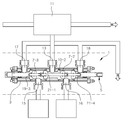
도 2는 본 발명의 일실시예에 따른 유로절환밸브가 적용되는 유동시스템을 도시한 부분 종단면도.
도 3은 도 2에 도시된 유로절환밸브의 작동로드가 우측단에 위치한 상태를 도시한 종단면도.
도 4는 도 2에 도시된 유로절환밸브의 작동로드가 좌측단에 위치한 상태를 도시한 종단면도.
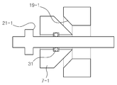
도 5는 도 2에 도시된 유로절환밸브의 포핏형 밸브체를 도시한 부분 종단면도.
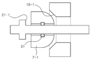
도 6은 도 2에 도시된 유로절환밸브의 구형 밸브체를 도시한 부분 종단면도.
도 7은 도 5에 도시된 포핏형 밸브체에 밀봉링이 장착된 상태를 도시한 도면.
도 8은 도 2에 도시된 유로절환밸브의 디스크형 밸브체를 도시한 부분 종단면도로, 밀봉링이 디스크에 장착된 상태를 도시한 도면.
도 9는 도 8에서 밀봉링이 관체의 안착부에 장착된 상태를 도시한 도면.
도 10은 도 2에 도시된 유로절환밸브의 작동로드가 정중앙에 위치한 상태를 도시한 종단면도.1 is a longitudinal sectional view showing a conventional flow path switching valve.
Figure 2 is a partial longitudinal cross-sectional view showing a flow system to which the flow path switching valve is applied according to an embodiment of the present invention.
Figure 3 is a longitudinal cross-sectional view showing a state in which the operating rod of the flow path switching valve shown in Figure 2 located at the right end.
Figure 4 is a longitudinal cross-sectional view showing a state in which the operating rod of the flow path switching valve shown in FIG.
5 is a partial longitudinal cross-sectional view showing the poppet-type valve body of the flow path switching valve shown in FIG.
6 is a partial longitudinal cross-sectional view showing a spherical valve element of the flow path switching valve shown in FIG.
7 is a view showing a state in which a sealing ring is mounted on the poppet-type valve body shown in FIG.
FIG. 8 is a partial longitudinal sectional view showing the disk-shaped valve body of the flow path switching valve shown in FIG. 2, showing a state in which a sealing ring is mounted on the disk. FIG.
9 is a view showing a state in which the sealing ring is mounted to the seating portion of the tube in FIG.
10 is a longitudinal sectional view showing a state in which an operating rod of the flow path switching valve shown in FIG. 2 is located at the center;
이하, 본 발명의 일실시예에 따른 유로절환밸브를 첨부도면을 참조하여 설명한다.Hereinafter, a flow path switching valve according to an embodiment of the present invention will be described with reference to the accompanying drawings.
본 발명의 유로절환밸브는 도 2 및 도 3에 도시된 바와 같이, 크게 관체(3), 작동로드(5), 및 가동밸브체(7-1,7-2,7-3,7-4)로 이루어지는 바, 유체공급원(11)으로부터 하나 또는 그 이상의 입구(13)를 통해 유입되는 작동유체를 둘 또는 그 이상의 출구(15,16)를 통해 선택적으로 교차 배출하도록 되어 있다. As shown in Figs. 2 and 3, the flow path switching valve of the present invention is largely a
여기에서, 상기 관체(3)는 유로절환밸브의 몸체를 이루는 부분으로, 긴 관 형태로 되어 있으며, 중앙에 하나 이상의 입구(13)가, 각 입구(13)의 양측에 하나씩 둘 이상의 출구(15,16)가, 그리고 양측단에 드레인구(17,18)가 각각 개방된다.Here, the
이때, 입구(13)는 도 2에 도시된 바와 같이 유체공급원(11)에 연결되어 관체(3)의 내부로 유체를 공급하도록 되어 있는 바, 필요에 따라 하나 이상으로 구비될 수도 있다. 이때, 공급원(11)에서 공급되는 유체 즉, 유로절환밸브(1)에 의해 유동이 제어되는 유체는 물 특히, 해수나 함수(鹹水;brine)와 같은 점성이 거의 없는 유체를 포함한다. 또한, 출구(15,16)는 관체(3)의 입구(13) 대향측에서 두 개 이상으로 개방되어 관체(3) 내부의 유체를 밸브체(7)의 동작에 따라 선택적으로 교차 배출하도록 되어 있다. 또한, 드레인구(17,18)는 관체(3)의 양측단에 개방되어 출구(15,16)를 통해 배출되지 못하고 배제된 관체(3) 내부의 유체를 유체공급원(11) 또는 기타의 저수원으로 드레인시키도록 되어 있다.At this time, the
한편, 관체(3)는 이와 같은 각각의 입구(13), 출구(15,16), 및 드레인구(17,18)가 인접한 다른 입구(13), 출구(15,16), 및 드레인구(17,18)와의 사이의 내주면 상에 안착부(19)가 각각 돌출되어 있는 바, 안착부(19-1,19-2) 사이의 내주면과 안착부(19-3,19-4)에서 관체(3) 끝면까지의 내주면은 도시된 것처럼 직경이 축소된 상태로 형성되는 것이 바람직하며, 상대적으로 나머지 내주면은 밸브체(7)가 이동할 수 있는 대경부를 이룬다. On the other hand, the
상기 작동로드(5)는 외부의 작동수단과 연결되어 관체(3) 내에서 밸브체(7)를 이동시켜 유로절환밸브(1)의 유로를 제어하는 부분으로서, 관체(3) 내에 동축 상으로 장착되는 바, 일측단이 유체 밀봉 상태로 관체(3) 외부로 노출되어 작동수단과 연결되어 관체(3) 내에서 축방향으로 전후진 왕복운동하도록 되어 있으며, 이를 위해 관체(3) 양단에 결합된 밀봉캡(29)을 통해 수밀을 유지한 상태로 미끄럼 이동 가능하게 지지된다.The actuating rod 5 is connected to an external actuating means to move the valve body 7 in the
또한, 작동로드(5)는 외주면 상에 끼워진 복수의 가동밸브체(7-1,7-2,7-3,7-4)를 가압하여 이동시키기 위해 외주면에 복수의 걸림부(21-1,21-2,21-3,21-4)가 상호 이격된 상태로 돌출 형성되는 바, 도 3에 도시된 바와 같이, 관체(3)의 입구(13)를 사이에 둔 걸림부(21-1,21-2) 중 좌측에 있는 걸림부(21-1)가 입구(13)를 사이에 둔 안착부(19-1,19-2) 중 좌측에 있는 안착부(19-1)로 입구(13)의 바로 좌측에 있는 가동밸브체(7-1)를 가압하여 안착시킨 때, 입구(13)를 사이에 둔 걸림부(21-1,21-2) 중 우측에 있는 걸림부(21-2)는 입구(13)를 통해 유입된 유체의 압력에 의해 입구(13)의 바로 우측에 있는 가동밸브체(7-2)가 우측 안착부(19-2)에서 떨어질 수 있도록 간섭을 일으키지 않는 위치에 형성되어 있고, 관체(3)의 좌측단에 위치하는 걸림부(21-3)는 좌측단 출구(15)와 좌측 드레인구(17) 사이에 위치하는 좌측단 안착부(19-3)에서 좌측단 가동밸브체(7-3)가 떨어지도록 가압할 수 있는 위치에 형성되어 있으며, 관체(3)의 우측단 걸림부(21-4)는 우측단 가동밸브체(7-4)가 우측단 출구(16)와 우측 드레인구(18) 사이에 위치하는 우측단 안착부(19-4)에 안착될 수 있도록 간섭을 일으키지 않는 위치에 형성되어 있다.In addition, the operation rod 5 includes a plurality of locking portions 21-1 on the outer circumferential surface in order to pressurize and move the plurality of movable valve bodies 7-1, 7-2, 7-3, 7-4 fitted on the outer circumferential surface. , 21-2, 21-3, 21-4 are formed to protrude in a state spaced apart from each other, as shown in Figure 3, the engaging portion 21- sandwiching the
마찬가지로, 작동로드(5)는 도 4에 도시된 바와 같이, 관체(3)의 입구(13)를 사이에 둔 걸림부(21-1,21-2) 중 우측에 있는 걸림부(21-2)가 입구(13)를 사이에 둔 안착부(19-1,19-2) 중 우측에 있는 안착부(19-2)로 입구(13)의 바로 우측에 있는 가동밸브체(7-2)를 가압하여 안착시킨 때, 입구(13)를 사이에 둔 걸림부(21-1,21-2) 중 좌측에 있는 걸림부(21-1)는 입구(13)를 통해 유입된 유체의 압력에 의해 입구(13)의 바로 좌측에 있는 가동밸브체(7-1)가 좌측 안착부(19-1)에서 떨어질 수 있도록 간섭을 일으키지 않는 위치에 형성되어 있고, 관체(3)의 우측단에 위치하는 걸림부(21-4)는 우측단 출구(16)와 우측 드레인구(18) 사이에 위치하는 우측단 안착부(19-4)에서 우측단 가동밸브체(7-4)가 떨어지도록 가압할 수 있는 위치에 형성되어 있으며, 관체(3)의 좌측단 걸림부(21-3)는 좌측단 가동밸브체(7-3)가 좌측단 출구(15)와 좌측 드레인구(17) 사이에 위치하는 좌측단 안착부(19-3)에 안착될 수 있도록 간섭을 일으키지 않는 위치에 형성되어 있다.Similarly, as shown in FIG. 4, the actuating rod 5 has a catching portion 21-2 on the right side of the catching portions 21-1 and 21-2 sandwiching the
이를 위해, 작동로드(5)는 원주면에 복수의 걸림부(21-1,21-2,21-3,21-4)가 돌출된 봉형태로 제작되면 되나, 복수의 단봉을 결합하여 구성하는 것이 보다 바람직하며, 각각의 단봉들은 다양한 형태로 조립될 수 있는 바, 그 한 예로 도 3 및 도 4에 도시된 바와 같이 볼트와 볼트구멍에 의한 결합방식으로 조립될 수도 있는데, 이에 따르면 작동로드(5)는 크게 중심봉(5-1), 말단봉(5-2), 그리고 연결봉(5-3)으로 이루어진다.To this end, the operating rod 5 may be made in the form of a rod protruding a plurality of engaging portions (21-1, 21-2, 21-3, 21-4) on the circumferential surface, it is configured by combining a plurality of single rods More preferably, each of the rods can be assembled in a variety of forms, for example, as shown in Figures 3 and 4 may be assembled by a coupling method by bolts and bolt holes, according to the operation rod (5) is composed of a central rod (5-1), a terminal rod (5-2), and a connecting rod (5-3).
여기에서, 중심봉(5-1)은 입구(13)를 사이에 둔 안착부(19-1,19-2) 사이의 구간에 즉, 작동로드(5)의 정중앙에 배치되는 바, 도시된 것처럼 양단에 볼트(23)가 가공된다. 또한, 말단봉(5-2)은 작동로드(5)의 양단에 결합되는 바, 관체(3)의 안착부(19-3,19-4) 바깥쪽 구간에 배치되며, 중심봉(5-1)을 향한 내측단에 볼트구멍(25)이 각각 가공되어 연결봉(5-3)의 볼트(23)를 결합하도록 되어 있다. 끝으로, 연결봉(5-3)은 중심봉(5-1)과 말단봉(5-2)을 연결하는 봉체로서, 중심봉(5-1)과 각각의 말단봉(5-2) 사이에 두 개 이상 복수개가 구비될 수 있는 바, 연결봉(5-3)의 중심봉(5-1)을 향한 내측단에는 볼트구멍(25)이, 말단봉(5-2)을 향한 외측단에는 볼트(23)가 가공되어 중심봉(5-1)에서 말단봉(5-2)까지 연쇄적으로 결합된다.Here, the center rod 5-1 is disposed in the section between the seating portions 19-1 and 19-2 with the
상기 복수의 가동밸브체(7-1,7-2,7-3,7-4)는 작동로드(5)의 외주면 상에 이동 가능하게 장착되어 작동로드(5)에 의해 출구(15,16) 및 드레인구(17,18)로의 유로가 선택적으로 교차 개폐되도록 하는 수단으로서, 각각의 안착부(19)를 향하여 일대일 대응하도록 각각의 걸림부(21-1,21-2,21-3,21-4) 사이에 배치된다. The plurality of movable valve bodies 7-1, 7-2, 7-3, and 7-4 are movably mounted on the outer circumferential surface of the actuating rod 5 and are discharged by the actuating rod 5 to the
또한, 각각의 가동밸브체(7-1,7-2,7-3,7-4)는 점성이 거의 없는 물과 같은 작동유체의 수밀을 기하기 위하여 도 3 내지 도 5에 도시된 것처럼 포핏 타입으로 형성되는 것이 바람직한 바, 이 포핏타입 가동밸브체(7-1,7-2,7-3,7-4)는 작동로드(5)와의 사이에 밀봉링(31)이 장착되어 작동로드(5) 상에서 이동하는 가동밸브체(7-1,7-2,7-3,7-4)와 작동로드(5) 표면 사이를 밀봉한다. 이때, 관체(3)의 안착부(19)는 포핏의 경사면이 밀착되도록 대응하는 형태의 경사면으로 형성된다.In addition, each of the movable valve bodies 7-1, 7-2, 7-3, 7-4 has a poppet as shown in Figs. 3 to 5 in order to achieve watertightness of a working fluid such as water having little viscosity. The poppet type movable valve body (7-1,7-2,7-3,7-4) is preferably formed in a type, and a sealing ring (31) is mounted between the actuation rod (5) and the actuation rod. (5) Seal between the movable valve body (7-1,7-2,7-3,7-4) moving on the surface of the operating rod (5). At this time, the seating part 19 of the
또한, 가동밸브체(7-1,7-2,7-3,7-4)는 도 6에 도시된 것처럼 경사면이 구형으로 가공되어도 무방하며, 도 7에 도시된 것처럼 경사면 상에 밀봉링(27)을 추가로 장착하여도 좋다.Further, the movable valve bodies 7-1, 7-2, 7-3, and 7-4 may be processed into a spherical surface as shown in FIG. 6, and a sealing ring (e.g., as shown in FIG. 27) may be additionally installed.
또한, 가동밸브체(7-1,7-2,7-3,7-4)는 도 8 및 도 9에 도시된 것처럼, 디스크 형태로 될 수도 있는데, 이때 안착부(19-1)는 평면이거나 디스크형 가동밸브체(7-1)의 디스크면과 대응하는 형태로 오목하게 형성될 수도 있으며, 가동밸브체(7-1) 또는 안착부(19-1) 어느 한 쪽에 장착됨으로써 밀봉링(27)이 안착부(19-1)와의 사이에 개재될 수도 있다. Further, the movable valve bodies 7-1, 7-2, 7-3, 7-4 may be in the form of discs, as shown in Figs. 8 and 9, wherein the seating portion 19-1 is flat Or it may be formed concave in a shape corresponding to the disk surface of the disk-type movable valve body (7-1), it is mounted on either the movable valve body (7-1) or the seating portion (19-1) sealing ring ( 27 may be interposed between the seating portion 19-1.
이제, 위와 같이 구성되는 본 발명의 유로절환밸브(1)의 작동을 설명하면 다음과 같다.Now, the operation of the flow
본 발명의 유로절환밸브(1)는 도 10에 도시된 중립 상태에서 작동로드(5)가 관체(3)의 정중앙에 위치하며, 이때 좌우측단의 가동밸브체(7-3,7-4)는 각각 대응하는 좌우측단의 안착부(19-3,19-4)에 안착되고, 입구(13)의 좌우측에 있는 가동밸브체(7-1,7-2)는 각각 대응하는 안착부(19-1,19-2)에서 떨어진다. 따라서, 도시된 것처럼 입구(13)를 통해 유체공급원(11)으로부터 관체(3) 안으로 유입된 작동유체는 좌우측 가동밸브체(19-1,19-2)를 통과하여 좌우 출구(15,16) 양쪽으로 동시에 배출된다. 이때, 좌우 드레인구(17,18)는 좌우측단의 가동밸브체(7-3,7-4)에 의해 작동유체의 유입이 막혀 있으므로, 작동유체의 배출은 없다. The flow
위와 같은 중립상태에서 외부의 작동수단에 의해 작동로드(5)가 관체(3)의 우측으로 이동하면, 입구(13) 좌측의 작동로드(5) 걸림부(21-1)가 입구(13) 좌측의 가동밸브체(7-1)를 가압하여 도 3에 도시된 바와 같이 입구(13) 좌측의 안착부(19-1)에 밀착시키며, 이에 따라 입구(13)에서 좌측 출구(15)로 이어지는 유로는 차단된다. 이와 동시에 입구(13) 우측의 걸림부(21-2)가 입구(13) 우측 안착부(19-2)에서 우측으로 충분히 이격되므로, 입구(13) 우측의 가동밸브체(7-2)는 입구(13)에서 유입되는 작동유체의 압력에 의해 우측 걸림부(21-2)까지 밀려 안착부(19-2)로부터 떨어지며, 이에 따라 입구(13)에서 우측 출구(16)로의 유로가 연결됨으로써 입구(13)로 유입된 작동유체는 우측 출구(16)로 배출된다. 이때, 좌측단 가동밸브체(7-3)는 좌측단 걸림부(21-3)에 의해 밀려 좌측단 안착부(19-3)에서 떨어지면서 좌측 출구(15)가 좌측 드레인구(17)로 개방되어 관체 좌측단에 수용된 작동유체를 드레인시키며, 우측단 가동밸브체(7-4)는 입구(13)로 유입되는 작동유체의 압력에 의해 우측단으로 가압되어 우측단 걸림부(19-4)에 밀착되면서 우측 출구(16)와 우측 드레인구(18) 사이의 연결은 차단된다. When the operating rod 5 moves to the right side of the
반대로, 작동로드(5)가 관체(3)의 좌측으로 이동하면, 입구(13) 우측의 작동로드(5) 걸림부(21-2)가 입구(13) 우측의 가동밸브체(7-2)를 가압하여 도 4에 도시된 바와 같이 입구(13) 우측의 안착부(19-2)에 밀착시킨다. 이에 따라 입구(13)에서 우측 출구(16)로 이어지는 유로는 차단되며, 입구(13) 좌측의 걸림부(21-1)는 입구(13) 좌측 안착부(19-1)에서 좌측으로 충분히 이격되므로, 입구(13) 좌측의 가동밸브체(7-1)는 입구(13)에서 유입되는 작동유체의 압력에 의해 좌측 안착부(19-1)로부터 떨어져 좌측 걸림부(21-1)까지 밀려 나간다. 이에 따라 입구(13)에서 좌측 출구(15)로의 유로가 이어지게 되며, 입구(13)로 유입된 작동유체는 좌측 출구(15)를 통해 외부로 배출된다. 이때, 우측단 가동밸브체(7-4)는 우측단 걸림부(21-4)에 의해 밀려 우측단 안착부(19-4)에서 떨어지며, 이에 따라 우측 출구(16)가 우측 드레인구(18)로 개방되어 관체 우측단에 수용된 작동유체를 드레인시킨다. 이와 동시에, 좌측단 가동밸브체(7-3)는 입구(13)로 유입되는 작동유체의 압력에 의해 좌측단으로 가압되어 좌측단 걸림부(19-3)에 밀착되면서 좌측 출구(15)와 좌측 드레인구(17) 사이의 연결을 차단하게 된다. On the contrary, when the actuating rod 5 moves to the left side of the
1 : 유로절환밸브 3 : 관체
5 : 작동로드 7-1,-2,-3,-4 : 가동밸브체
11 : 유체공급원 13 : 입구
15, 16 : 좌우측 출구 17, 18 : 좌우측 드레인구
19-1,-2,-3,-4 : 안착부 21-1,-2,-3,-4 : 걸림부
23 : 볼트 25 : 볼트구멍1: flow path switching valve 3: pipe
5: operating rod 7-1, -2, -3, -4: movable valve body
11
15, 16: left and
19-1, -2, -3, -4: Seating part 21-1, -2, -3, -4: Hanging part
23: bolt 25: bolt hole
Claims (6)
상기 관체(3) 내에 동축 상으로 장착되되, 복수의 걸림부(21-1,21-2,21-3,21-4)가 외주면 상에 상호 이격된 상태로 돌출되고, 유체밀봉 상태로 외부 노출된 일측단에 작동수단이 연결되어 상기 작동수단에 의해 상기 관체(3) 내에서 축방향으로 전후진 왕복운동하도록 되어 있는 작동로드(5); 및
상기 작동로드(5) 외주면 상에 이동 가능하게 장착되어 상기 각각의 안착부(19)를 향하여 일대일 대응하도록 상기 각각의 걸림부(21-1,21-2,21-3,21-4) 사이에 배치되어 있는 복수의 가동밸브체(7-1,7-2,7-3,7-4);를 포함하여 구성되는 것을 특징으로 하는 유로절환밸브.One or more inlets 13 open to be connected to the fluid source 11 to supply fluid therein, and two or more outlets 15 which are open to both sides of the respective inlets 13 to selectively cross-discharge fluid therein; 16 and drain openings 17 and 18, which are open at both ends and are configured to drain the fluid inside without being discharged through the outlets 15 and 16, respectively, and the respective inlets 13 Pipe body 3 in which seating portions 19 protrude from the inner circumferential surfaces between the outlets 15 and 16 and the drain ports 17 and 18, respectively;
Mounted coaxially in the tubular body 3, the plurality of locking parts (21-1, 21-2, 21-3, 21-4) protrude in a state spaced apart from each other on the outer circumferential surface, the outside in a fluid sealed state An actuating rod 5 connected to the exposed one end thereof such that the actuating rod is reciprocated forward and backward in the axial direction by the actuating means; And
Between the engaging portions 21-1, 21-2, 21-3, and 21-4 so as to be movable on the outer circumferential surface of the working rod 5 so as to correspond one-to-one toward the seating portion 19. And a plurality of movable valve bodies (7-1,7-2,7-3,7-4) disposed in the flow path switching valve.
상기 입구(13)를 사이에 둔 상기 걸림부(21-1,21-2) 중 일측 걸림부(21-1)에 의해 가압된 상기 가동밸브체(7-1)가 상기 입구(13)를 사이에 둔 상기 안착부(19-1,19-2) 중 일측 안착부(19-1)에 안착된 때,
상기 타측 걸림부(21-2)는 상기 입구(13)를 통해 유입된 유체의 압력에 의해 상기 가동밸브체(7-2)를 상기 타측 안착부(19-2)에서 떨어뜨릴 수 있는 위치에 형성되고,
상기 일측단 걸림부(21-3)는 상기 일측단 출구(15)와 상기 일측 드레인구(17) 사이의 상기 일측단 안착부(19-3)에서 상기 가동밸브체(7-3)를 떨어뜨릴 수 있는 위치에 형성되고,
상기 타측단 걸림부(21-4)는 상기 타측단 출구(16)와 상기 타측 드레인구(18) 사이의 상기 타측단 안착부(19-4)에 상기 가동밸브체(7-4)가 안착될 수 있도록 하는 위치에 형성되는 것을 특징으로 하는 유로절환밸브. The method according to claim 1,
The movable valve body 7-1, which is pressed by one side locking portion 21-1, of the locking portions 21-1 and 21-2 interposed between the inlets 13, opens the inlet 13. When seated on one of the seating portion (19-1) of the seating portion (19-1, 19-2) in between,
The other locking portion 21-2 is located at a position where the movable valve body 7-2 can be dropped from the other seating portion 19-2 by the pressure of the fluid flowing through the inlet 13. Formed,
The one end engaging portion 21-3 separates the movable valve body 7-3 from the one end mounting portion 19-3 between the one end of the outlet 15 and the one side drain port 17. Formed in a position to be lifted,
The movable valve body 7-4 is seated on the other end seating portion 19-4 between the other end outlet 16 and the other side drain port 18. The flow path switching valve, characterized in that formed in a position to be.
상기 입구(13)를 사이에 둔 상기 걸림부(21-1,21-2) 중 타측 걸림부(21-2)에 의해 가압된 상기 가동밸브체(7-2)가 상기 입구(13)를 사이에 둔 상기 안착부(19-1,19-2) 중 타측 안착부(19-2)에 안착된 때,
상기 일측 걸림부(21-1)는 상기 입구(13)를 통해 유입된 유체의 압력에 의해 상기 가동밸브체(7-1)를 상기 일측 안착부(19-1)에서 떨어뜨릴 수 있는 위치에 형성되고,
상기 일측단 걸림부(21-3)는 상기 일측단 출구(15)와 상기 일측 드레인구(17) 사이의 상기 일측단 안착부(19-3)에 상기 가동밸브체(7-3)가 안착될 수 있도록 하는 위치에 형성되고,
상기 타측단 걸림부(21-4)는 상기 타측단 출구(16)와 상기 타측 드레인구(18) 사이의 상기 타측단 안착부(19-4)에서 상기 가동밸브체(7-4)를 떨어뜨릴 수 있는 위치에 형성되는 것을 특징으로 하는 유로절환밸브. The method according to claim 1 or 2,
The movable valve body 7-2 pressurized by the other locking portion 21-2 among the locking portions 21-1 and 21-2 with the inlet 13 interposed therebetween. When seated on the other seating portion 19-2 of the seating portion (19-1, 19-2) sandwiched between,
The one locking portion 21-1 is positioned at a position where the movable valve body 7-1 can be dropped from the one seating portion 19-1 by the pressure of the fluid flowing through the inlet 13. Formed,
The one end locking portion 21-3 seats the movable valve body 7-3 on the one end mounting portion 19-3 between the one end outlet 15 and the one side drain port 17. Is formed in such a way that
The other end catching portion 21-4 separates the movable valve body 7-4 from the other end seating portion 19-4 between the other end outlet 16 and the other drain hole 18. The flow path switching valve, characterized in that formed in the position to be lowered.
상기 작동로드(5)는 상기 안착부(19-1,19-2) 사이의 구간에 배치되며, 양단에 볼트(23)가 가공되어 있는 중심봉(5-1);
상기 안착부(19-3,19-4) 바깥쪽 구간에 배치되며, 상기 중심봉(5-1)을 향한 내측단에 볼트구멍(25)이 가공되어 있는 말단봉(5-2); 및
상기 중심봉(5-1)과 각각의 상기 말단봉(5-2) 사이에 배치되며, 상기 중심봉(5-1)을 향한 내측단에는 볼트구멍(25)이, 상기 말단봉(5-2)을 향한 외측단에는 볼트(23)가 가공되어 있는 연결봉(5-3);으로 이루어지는 것을 특징으로 하는 유로절환밸브.The method of claim 3,
The operating rod (5) is disposed in the section between the seating portion (19-1, 19-2), the central rod (5-1) is processed at both ends of the bolt (23);
An end rod 5-2 disposed in an outer section of the seating portion 19-3 and 19-4, and having a bolt hole 25 formed at an inner end thereof toward the center rod 5-1; And
It is disposed between the center bar (5-1) and each of the end bars (5-2), the bolt hole 25 at the inner end toward the center bar (5-1), the end bar (5-2) The flow path switching valve, characterized in that consisting of; connecting rod (5-3) is processed at the outer end toward the bolt (23).
상기 가동밸브체(7-1,7-2,7-3,7-4)는 포핏, 디스크, 또는 반구 형태로 되어 있으며, 상기 안착부(19-1,19-2,19-3,19-4)는 상기 포핏의 경사면, 상기 디스크의 평면, 상기 반구의 구면과 각각 밀착되도록 경사면 또는 평면 형태로 되어 있는 것을 특징으로 하는 유로절환밸브. The method of claim 3,
The movable valve bodies 7-1, 7-2, 7-3, and 7-4 are in the form of poppets, discs, or hemispheres, and the seating portions 19-1, 19-2, 19-3, 19 -4) is a flow path switching valve, characterized in that the inclined surface or planar shape to be in close contact with the inclined surface of the poppet, the plane of the disk, the spherical surface of the hemisphere respectively.
상기 가동밸브체(7-1,7-2,7-3,7-4)와 상기 안착부(19-1,19-2,19-3,19-4) 사이에는 상기 가동밸브체(7-1,7-2,7-3,7-4) 또는 상기 안착부(19-1,19-2,19-3,19-4)의 어느 한 쪽에 고정된 밀봉링(27)이 개재되어 있는 것을 특징으로 하는 유로절환밸브.The method of claim 5,
The movable valve body 7 is provided between the movable valve body 7-1,7-2,7-3,7-4 and the seating portion 19-1,19-2,19-3,19-4. -1,7-2,7-3,7-4) or the sealing ring 27 fixed to either of the seating portion (19-1,19-2,19-3,19-4) is interposed Flow path switching valve characterized in that.
Priority Applications (4)
| Application Number | Priority Date | Filing Date | Title |
|---|---|---|---|
| KR20100105867A KR101206194B1 (en) | 2010-10-28 | 2010-10-28 | Flow path switching valve |
| PCT/KR2010/008069 WO2012057391A1 (en) | 2010-10-28 | 2010-11-16 | Flow path conversion valve |
| US13/280,568 US8789559B2 (en) | 2010-10-28 | 2011-10-25 | Flow path switching valve |
| DE201110054828 DE102011054828B4 (en) | 2010-10-28 | 2011-10-26 | Flow-reversing valve |
Applications Claiming Priority (1)
| Application Number | Priority Date | Filing Date | Title |
|---|---|---|---|
| KR20100105867A KR101206194B1 (en) | 2010-10-28 | 2010-10-28 | Flow path switching valve |
Publications (2)
| Publication Number | Publication Date |
|---|---|
| KR20120044544A true KR20120044544A (en) | 2012-05-08 |
| KR101206194B1 KR101206194B1 (en) | 2012-11-28 |
Family
ID=45994085
Family Applications (1)
| Application Number | Title | Priority Date | Filing Date |
|---|---|---|---|
| KR20100105867A KR101206194B1 (en) | 2010-10-28 | 2010-10-28 | Flow path switching valve |
Country Status (2)
| Country | Link |
|---|---|
| KR (1) | KR101206194B1 (en) |
| WO (1) | WO2012057391A1 (en) |
Cited By (1)
| Publication number | Priority date | Publication date | Assignee | Title |
|---|---|---|---|---|
| RU2779815C1 (en) * | 2022-01-18 | 2022-09-13 | Александр Михайлович Юрасов | Stop valve |
Families Citing this family (2)
| Publication number | Priority date | Publication date | Assignee | Title |
|---|---|---|---|---|
| CN104061342B (en) * | 2014-06-04 | 2016-06-08 | 蔡宇峰 | A kind of four-way valve device being applied to VOCs treatment |
| CN110145616A (en) * | 2019-04-22 | 2019-08-20 | 杭州神林电子有限公司 | A kind of mechanical switching devices |
Family Cites Families (5)
| Publication number | Priority date | Publication date | Assignee | Title |
|---|---|---|---|---|
| JPH0734262U (en) * | 1993-11-30 | 1995-06-23 | 豊興工業株式会社 | Direction switching valve |
| US5797429A (en) * | 1996-03-11 | 1998-08-25 | Desalco, Ltd. | Linear spool valve device for work exchanger system |
| JPH1137336A (en) | 1997-07-23 | 1999-02-12 | Tokimec Inc | Pilot operation type high-speed directional control valve |
| JP4276725B2 (en) * | 1999-02-18 | 2009-06-10 | 株式会社コガネイ | Direct acting switching valve and its assembly method |
| JP4415357B2 (en) * | 2006-02-08 | 2010-02-17 | 吉冨 昭三 | Cylinder operating direction switching device |
-
2010
- 2010-10-28 KR KR20100105867A patent/KR101206194B1/en active IP Right Grant
- 2010-11-16 WO PCT/KR2010/008069 patent/WO2012057391A1/en active Application Filing
Cited By (1)
| Publication number | Priority date | Publication date | Assignee | Title |
|---|---|---|---|---|
| RU2779815C1 (en) * | 2022-01-18 | 2022-09-13 | Александр Михайлович Юрасов | Stop valve |
Also Published As
| Publication number | Publication date |
|---|---|
| KR101206194B1 (en) | 2012-11-28 |
| WO2012057391A1 (en) | 2012-05-03 |
Similar Documents
| Publication | Publication Date | Title |
|---|---|---|
| EP3532755B1 (en) | Reversing valve and household water purifier including same technical field | |
| KR101369216B1 (en) | Pilot-operated three-position switching valve | |
| KR101630004B1 (en) | Diaphragm valve | |
| EP2751462B1 (en) | Valve | |
| CN102734500A (en) | Poppet valve assembly for controlling pneumatic actuator | |
| RU2007121790A (en) | HYDRAULIC CONTROL VALVE WITH INTEGRATED DOUBLE ACTUATORS | |
| CN107314002A (en) | Pressure holding valve device for the flush loop of the hydraulic circuit of closure | |
| KR101206194B1 (en) | Flow path switching valve | |
| US8408237B2 (en) | Modular spool valve | |
| US8789559B2 (en) | Flow path switching valve | |
| US10119478B2 (en) | High reliability high flow redundant trip block | |
| US9989164B1 (en) | Air-operated, magnetic, non-stall air directional control valve | |
| RU2643276C2 (en) | Hydraulic valve of the axial type having a linear driving mechanism (options) | |
| RU99845U1 (en) | LINEAR VALVE | |
| RU77379U1 (en) | MULTI-WAY FLOW SWITCH | |
| RU192042U1 (en) | TWO-LINE TWO-POSITION HYDRAULIC DISTRIBUTOR | |
| RU2495309C1 (en) | Control valve | |
| JP2007232018A (en) | Valve mechanism, pressurized fluid device operation maintaining mechanism and bellows valve | |
| RU2355929C1 (en) | Glove valve | |
| JP6227520B2 (en) | Internal pilot type 3 port selector valve | |
| RU45803U1 (en) | MANAGEMENT VALVE | |
| RU2443922C2 (en) | Valve with linear actuator | |
| RU2232325C2 (en) | Sealing device for movable slide valve connections | |
| CN110159771B (en) | Combined control mechanism | |
| RU2285853C1 (en) | Valve |
Legal Events
| Date | Code | Title | Description |
|---|---|---|---|
| A201 | Request for examination | ||
| E902 | Notification of reason for refusal | ||
| E701 | Decision to grant or registration of patent right | ||
| GRNT | Written decision to grant | ||
| FPAY | Annual fee payment |
Payment date: 20151112 Year of fee payment: 4 |
|
| FPAY | Annual fee payment |
Payment date: 20161013 Year of fee payment: 5 |
|
| FPAY | Annual fee payment |
Payment date: 20170928 Year of fee payment: 6 |
|
| FPAY | Annual fee payment |
Payment date: 20181101 Year of fee payment: 7 |
|
| FPAY | Annual fee payment |
Payment date: 20191024 Year of fee payment: 8 |