KR20120042440A - Apparatus and method for visualizing assembly process - Google Patents
Apparatus and method for visualizing assembly process Download PDFInfo
- Publication number
- KR20120042440A KR20120042440A KR1020100104135A KR20100104135A KR20120042440A KR 20120042440 A KR20120042440 A KR 20120042440A KR 1020100104135 A KR1020100104135 A KR 1020100104135A KR 20100104135 A KR20100104135 A KR 20100104135A KR 20120042440 A KR20120042440 A KR 20120042440A
- Authority
- KR
- South Korea
- Prior art keywords
- assembly process
- unit
- assembly
- color
- parts
- Prior art date
Links
Images


Classifications
-
- G—PHYSICS
- G09—EDUCATION; CRYPTOGRAPHY; DISPLAY; ADVERTISING; SEALS
- G09B—EDUCATIONAL OR DEMONSTRATION APPLIANCES; APPLIANCES FOR TEACHING, OR COMMUNICATING WITH, THE BLIND, DEAF OR MUTE; MODELS; PLANETARIA; GLOBES; MAPS; DIAGRAMS
- G09B25/00—Models for purposes not provided for in G09B23/00, e.g. full-sized devices for demonstration purposes
- G09B25/02—Models for purposes not provided for in G09B23/00, e.g. full-sized devices for demonstration purposes of industrial processes; of machinery
-
- G—PHYSICS
- G09—EDUCATION; CRYPTOGRAPHY; DISPLAY; ADVERTISING; SEALS
- G09B—EDUCATIONAL OR DEMONSTRATION APPLIANCES; APPLIANCES FOR TEACHING, OR COMMUNICATING WITH, THE BLIND, DEAF OR MUTE; MODELS; PLANETARIA; GLOBES; MAPS; DIAGRAMS
- G09B25/00—Models for purposes not provided for in G09B23/00, e.g. full-sized devices for demonstration purposes
-
- G—PHYSICS
- G06—COMPUTING; CALCULATING OR COUNTING
- G06T—IMAGE DATA PROCESSING OR GENERATION, IN GENERAL
- G06T17/00—Three dimensional [3D] modelling, e.g. data description of 3D objects
Landscapes
- Engineering & Computer Science (AREA)
- Physics & Mathematics (AREA)
- General Physics & Mathematics (AREA)
- Theoretical Computer Science (AREA)
- Business, Economics & Management (AREA)
- Educational Administration (AREA)
- Educational Technology (AREA)
- Computer Graphics (AREA)
- Geometry (AREA)
- Software Systems (AREA)
- Processing Or Creating Images (AREA)
Abstract
Description
본 발명은 조립 과정 가시화 기술에 관한 것이다. 특히, 본 발명은 제품의 조립 과정을 단계별로 상세하고 직관적으로 파악할 수 있도록 하는 조립 과정 가시화 장치 및 방법에 관한 것이다. The present invention relates to assembly process visualization techniques. In particular, the present invention relates to an assembly process visualization apparatus and method for enabling a detailed and intuitive understanding of a product assembly process step by step.
조립 과정은 다수개의 부품을 상호 결합하여 완성품 단계의 제품으로 구성하는 일련의 작업 과정이다. 그리고, 조립 과정은 다양한 목적에 의하여, 산업 현장의 근로자, 학교의 학생, 가정의 어린아이 등을 대상으로 교육 및 제시될 필요가 있다. 이러한, 조립 과정은 다수개의 각기 다른 부품을 상호 결합해야 하기 때문에 조립 과정 매뉴얼이 필요하다. 그런데, 대부분의 조립 과정 매뉴얼은 간단한 텍스트와 그림으로만 표현이 되어 있어, 쉽고 직관적인 조립 수행 방법을 제시하지 못하고 있다.The assembly process is a series of tasks that combine multiple parts together to form a finished product. In addition, the assembly process needs to be educated and presented to workers at industrial sites, students at schools, children at home, and the like, for various purposes. This assembly process requires assembly process manuals because a number of different components must be joined together. However, most of the assembly process manuals are represented only by simple text and pictures, and thus do not suggest an easy and intuitive assembly method.
예를 들어, 산업 현장의 근로자가 복잡한 기계를 조립하거나, 가정에서 어린아이가 유아용 블록을 연결하여 장난감 자동차 등의 완성품을 만드는 경우, 아날로그 방식의 기존 종이 기반의 조립 과정 매뉴얼은 직관적이지 않다. 따라서, 근로자 또는 어린아이 즉, 조립자가 조립을 하는데 상당한 시간이 소요될 뿐 아니라, 부서진 부분을 복원하는 재조립 과정에서도 조립 과정 매뉴얼의 파악 및 조립에 상당한 시간이 소요된다.For example, when an industrial worker assembles a complex machine or a child connects a baby block at home to make a finished product such as a toy car, the analog paper-based assembly process manual is not intuitive. Therefore, not only it takes a considerable time for the worker or the child, that is, the assembler to assemble, but also the reassembly process of restoring the broken part takes a considerable time to identify and assemble the assembly process manual.
상기한 과제를 해결하기 위하여 본 발명은, 제품의 조립 과정을 단계별로 3차원 입체 영상으로 제시하여, 사용자가 조립 과정을 직관적으로 빠르게 이해할 수 있게 하는 것을 목적으로 한다. In order to solve the above problems, an object of the present invention is to present a three-dimensional stereoscopic image of a product assembly step by step, so that the user can intuitively and quickly understand the assembly process.
그리고, 본 발명은 조립 과정 매뉴얼에 있어서, 각 부품에 대하여 기 저장된 색상 및 재질뿐만 아니라 기 저장된 다양한 색상 및 재질을 혼합한 신규한 색상 및 재질을 적용하는 것을 목적으로 한다.In addition, in the assembly process manual, an object of the present invention is to apply a new color and material mixed with various pre-stored colors and materials as well as pre-stored colors and materials.
또한, 본 발명은 실제 부품의 조립 단계를 영상으로 인식 후, 사용자에게 다음 조립될 부품에 대한 안내를 하는 것을 목적으로 한다. In addition, an object of the present invention is to guide the user to the next assembly to be assembled after recognizing the assembly step of the actual part as an image.
또한, 본 발명은 부품 간의 결합 방법에 따라 부품 간의 접착 부위를 다르게 표현하여, 사용자가 조립 과정 매뉴얼을 통해 직관적으로 부품 간의 결합 방법을 용이하게 파악할 수 있는 것을 목적으로 한다. In addition, an object of the present invention is to express different parts of the bonding between the parts according to the method of joining between parts, the user can easily grasp the method of joining between the parts intuitively through the assembly process manual.
상기한 목적을 달성하기 위한 본 발명에 따른 조립 과정 가시화 장치는 다수개의 부품을 조립하여 완성품이 완성되는 조립 과정을, 단계별로 3차원 입체 영상으로 모델링하여 조립 과정 매뉴얼을 저작하는 저작부; 상기 저작부에서 저작된 상기 조립 과정 매뉴얼을 저장하는 저장부; 및 상기 저장부에 저장된 상기 조립 과정 매뉴얼을 사용자에게 단계별로 가시화하는 가시화부를 포함한다.An assembly process visualization apparatus according to the present invention for achieving the above object is an authoring unit for authoring the assembly process manual by modeling a three-dimensional three-dimensional image of the assembly process to complete the finished product by assembling a plurality of parts; A storage unit for storing the assembly process manual written in the authoring unit; And a visualization unit configured to visualize the assembly process manual stored in the storage unit step by step.
이 때, 상기 가시화부는 실제 부품의 조립 단계를 영상으로 인식하는 조립 정보 인식부; 상기 조립 과정 매뉴얼을 상기 사용자에게 디스플레이하는 디스플레이부; 및 상기 조립 정보 인식부에서 인식된 상기 영상을 분석하여, 상기 실제 부품의 조립 단계에 대응하는 상기 조립 과정 매뉴얼의 조립 단계를 검색하고, 상기 조립 과정 매뉴얼의 상기 조립 단계의 상기 조립 과정이 상기 디스플레이부에 디스플레이되도록 제어하는 제어부를 포함할 수 있다.At this time, the visualization unit assembly information recognition unit for recognizing the assembly step of the actual component as an image; A display unit configured to display the assembly process manual to the user; And analyzing the image recognized by the assembly information recognizing unit to search for an assembly step of the assembly process manual corresponding to the assembling step of the actual component, wherein the assembly process of the assembly step of the assembly process manual is the display. It may include a control unit for controlling to be displayed on the unit.
이 때, 상기 가시화부는 상기 사용자가 상기 저장부에 저장된 상기 조립 과정 매뉴얼의 조립 단계를 선택할 수 있도록 형성되는 조립 과정 매뉴얼 입출력부; 상기 조립 과정 매뉴얼을 상기 사용자에게 디스플레이하는 디스플레이부; 및 상기 조립 과정 매뉴얼 입출력부를 통하여 상기 사용자가 선택한 상기 조립 단계의 상기 조립 과정이 상기 디스플레이부에 디스플레이 되도록 제어하는 제어부를 포함할 수 있다.At this time, the visualization unit is an assembly process manual input and output unit is formed so that the user can select the assembly step of the assembly process manual stored in the storage unit; A display unit configured to display the assembly process manual to the user; And a controller configured to control the assembly process of the assembly step selected by the user to be displayed on the display unit through the assembly process manual input / output unit.
이 때, 상기 조립 과정 매뉴얼 입출력부는 상기 사용자가 상기 조립 과정 매뉴얼의 외부출력을 선택할 수 있도록 형성되고, 상기 제어부는 상기 사용자가 상기 조립 과정 매뉴얼 입출력부에서 상기 외부출력을 선택하는 경우, 상기 조립 과정 매뉴얼이 외부 디스플레이 기기에 디스플레이 되도록 제어할 수 있다.In this case, the assembly process manual input / output unit may be configured to allow the user to select an external output of the assembly process manual, and the control unit may be configured to perform the assembly process when the user selects the external output from the assembly process manual input / output unit. The manual can be controlled to be displayed on an external display device.
이 때, 상기 저작부는 다수개의 상기 부품의 3차원 기하 정보를 분석하여, 다수개의 상기 부품의 3차원 모델링 데이터를 제작하는 3D 모델링 데이터 제작부; 다수개의 상기 부품의 상기 3차원 모델링 데이터에 색상 및 재질을 표현하는 색상/재질 표현부; 및 상기 색상/재질 표현부를 통해 색상 및 재질이 표현된 다수개의 상기 부품의 상기 3차원 모델링 데이터에, 다수개의 상기 부품을 통해 상기 완성품을 완성하는 조립 동작에 대한 움직임 데이터를 포함시켜, 상기 조립 과정 매뉴얼을 저작하는 애니메이션 동작 표현부를 포함하는 것을 특징으로 하는 조립 과정 가시화 장치.At this time, the authoring unit is a 3D modeling data production unit for producing three-dimensional modeling data of the plurality of parts by analyzing the three-dimensional geometric information of the plurality of parts; A color / material representation unit expressing a color and a material in the three-dimensional modeling data of a plurality of parts; And motion data on an assembly operation of completing the finished product through the plurality of parts in the three-dimensional modeling data of the plurality of parts in which color and material are expressed through the color / material expression unit. Assembly process visualization apparatus comprising an animation motion representation for authoring the manual.
이 때, 상기 저장부는 상기 부품의 상기 3차원 모델링 데이터에 적용하기 위한 색상 및 재질의 데이터를 더 저장하고 있으며, 상기 색상/재질 표현부는 서로 다른 두 색상을 혼합한 색상에 대한 디지털 데이터 값을 생성하여 상기 저장부에 저장하는 신규 색상 생성부; 및 상기 저장부에 저장된 상기 색상 및 상기 재질의 데이터를 바탕으로 상기 부품의 색상 및 재질을 정의하는 색상/재질 정의부를 포함할 수 있다. 이 때, 상기 저장부는 상기 부품의 상기 3차원 모델링 데이터에 적용하기 위한 색상 및 재질의 데이터를 더 저장하고 있으며, 상기 색상/재질 표현부는 서로 다른 두 재질을 혼합한 재질에 대한 디지털 데이터 값을 생성하여 상기 저장부에 저장하는 신규 재질 생성부; 및 상기 저장부에 저장된 상기 색상 및 상기 재질의 데이터를 바탕으로 상기 부품의 색상 및 재질을 정의하는 색상/재질 정의부를 포함할 수 있다. In this case, the storage unit further stores data of color and material for applying to the 3D modeling data of the component, and the color / material representation unit generates digital data values for colors in which two different colors are mixed. A new color generator to store the color in the storage unit; And a color / material definition unit defining a color and a material of the part based on the color and the data of the material stored in the storage unit. At this time, the storage unit further stores the data of the color and material for applying to the three-dimensional modeling data of the component, the color / material representation unit generates a digital data value for a material mixed with two different materials New material generation unit to store the storage unit; And a color / material definition unit defining a color and a material of the part based on the color and the data of the material stored in the storage unit.
이 때, 상기 애니메이션 동작 표현부는 다수개의 상기 부품 간의 결합 관계 정보를 바탕으로, 다수개의 상기 부품이 기 정하여진 영역 내에서 상호 결합하도록 상기 부품 간의 결합 제한 조건을 정의하는 제한 조건 정의부; 다수개의 상기 부품 간의 결합 관계 정보를 바탕으로, 다수개의 상기 부품이 기 정하여진 조립 포인트 및 조립 라인을 따라 상호 결합하도록 하는 방식에 대하여 정의하는 스냅 드래깅 정의부; 및 다수개의 상기 부품을 통해 상기 완성품을 완성하는 상기 조립 과정에 대한 움직임 데이터를 단계별로 정의하는 제스처 기반 동작 정의부를 포함할 수 있다.In this case, the animation motion expression unit may include: a constraint condition defining unit defining a coupling constraint between the parts such that the plurality of parts are coupled to each other within a predetermined area based on the coupling relationship information between the plurality of parts; A snap dragging definition unit defining a method of allowing the plurality of parts to be coupled to each other along a predetermined assembly point and an assembly line based on the coupling relationship information between the plurality of parts; And a gesture-based motion definition unit that defines step by step motion data for the assembly process of completing the finished product through a plurality of parts.
이 때, 상기 애니메이션 동작 표현부는 다수개의 상기 부품 간의 접착 방법에 따라, 서로 다르게 상기 부품 간의 접착 부위를 표현하는 접착 방법 정의부를 포함할 수 있다.In this case, the animation motion expression unit may include an adhesion method definition unit that expresses an adhesion portion between the parts differently according to the adhesion method between the plurality of parts.
이 때, 상기 3D 모델링 데이터 제작부는 카메라 영상을 통한 형상 검출 기반의 셰이프 모델링, 스케치 기반의 셰이프 모델링, 템플릿 기반의 모델링 및 클립아트 기반의 텍스쳐 매핑 중의 적어도 하나의 방법을 통해 상기 3차원 모델링 데이터를 제작할 수 있다.
In this case, the 3D modeling data manufacturing unit performs the 3D modeling data through at least one of shape detection based shape modeling through a camera image, sketch based shape modeling, template based modeling, and clip art based texture mapping. I can make it.
또한, 상기한 목적을 달성하기 위한 본 발명에 따른 조립 과정 가시화 방법은 다수개의 부품을 조립하여 완성품이 완성되는 조립 과정을, 단계별로 3차원 입체 영상으로 모델링하여 조립 과정 매뉴얼을 저작하는 조립 과정 매뉴얼 저작 단계; 상기 조립 과정 매뉴얼 저작 단계에서 저작된 상기 조립 과정 매뉴얼을 저장부에 저장하는 조립 과정 매뉴얼 저장 단계; 및 상기 매뉴얼 저장 단계에서 저장된 상기 조립 과정 매뉴얼을 사용자에게 단계별로 가시화하는 조립 과정 매뉴얼 가시화 단계를 포함한다.In addition, the assembly process visualization method according to the present invention for achieving the above object is an assembly process manual for authoring the assembly process manual by modeling a three-dimensional three-dimensional image of the assembly process to complete the finished product by assembling a plurality of parts Mastication step; An assembly process manual storage step of storing the assembly process manual written in the assembly process manual authoring step in a storage unit; And an assembly process manual visualization step of visualizing the assembly process manual stored in the manual storing step by step.
이 때, 실제 부품의 조립 단계를 영상으로 인식하는 조립 정보 인식 단계; 및 상기 조립 정보 인식 단계에서 인식된 상기 영상을 분석하여, 상기 실제 부품의 조립 단계에 대응하는 상기 조립 과정 매뉴얼의 조립 단계를 검색하는 조립 과정 매뉴얼 검색 단계를 더 포함하며, 상기 조립 과정 매뉴얼 가시화 단계는 상기 조립 정보 검색 단계에서 검색된 상기 조립 과정 매뉴얼의 상기 조립 단계의 상기 조립 과정을 디스플레이 할 수 있다.At this time, the assembly information recognition step of recognizing the assembly step of the actual part as an image; And an assembly process manual search step of searching for an assembly step of the assembly process manual corresponding to the assembling step of the actual component by analyzing the image recognized in the assembly information recognition step, and visualizing the assembly process manual step. May display the assembly process of the assembly step of the assembly process manual retrieved in the assembly information search step.
이 때, 상기 조립 과정 매뉴얼 저작 단계는 다수개의 상기 부품의 3차원 기하 정보를 분석하여, 다수개의 상기 부품의 3차원 모델링 데이터를 제작하는 3D 모델링 데이터 제작 단계; 다수개의 상기 부품의 상기 3차원 모델링 데이터에 색상 및 재질을 표현하는 색상/재질 표현 단계; 및 상기 색상/재질 표현 단계를 통해 색상 및 재질이 표현된 다수개의 상기 부품의 상기 3차원 모델링 데이터에, 다수개의 상기 부품을 통해 상기 완성품을 완성하는 조립 동작에 대한 움직임 데이터를 포함시켜, 상기 조립 과정 매뉴얼을 저작하는 애니메이션 동작 표현 단계를 포함할 수 있다.At this time, the assembly process manual authoring step is to analyze the three-dimensional geometric information of the plurality of parts, to produce a 3D modeling data for producing the three-dimensional modeling data of the plurality of parts; A color / material representation step of expressing a color and a material in the three-dimensional modeling data of a plurality of parts; And motion data about an assembly operation of completing the finished product through the plurality of parts in the three-dimensional modeling data of the plurality of parts in which color and material are expressed through the color / material expression step. An animation motion expression step of authoring a process manual may be included.
이 때, 상기 색상/재질 표현 단계는 서로 다른 두 색상을 혼합한 색상에 대한 디지털 데이터 값을 생성하여 상기 부품의 상기 3차원 모델링 데이터에 적용할 수 있다.In this case, the color / material expression step may generate a digital data value for a color of two different colors and apply it to the three-dimensional modeling data of the part.
이 때, 상기 색상/재질 표현 단계는 서로 다른 두 재질을 혼합한 재질에 대한 디지털 데이터 값을 생성하여 상기 부품의 상기 3차원 모델링 데이터에 적용할 수 있다.In this case, the color / material expression step may generate a digital data value for a material in which two different materials are mixed and apply the generated three-dimensional modeling data of the part.
이 때, 상기 애니메이션 동작 표현 단계는 다수개의 상기 부품간의 결합 관계 정보를 바탕으로, 다수개의 상기 부품이 기 정하여진 영역 내에서 상호 결합하도록 상기 부품 간의 결합 제한 조건을 정의하는 제한 조건 정의 단계; 다수개의 상기 부품 간의 결합 관계 정보를 바탕으로, 다수개의 상기 부품이 기 정하여진 조립 포인트 및 조립 라인을 따라 상호 결합되도록 하는 방식에 대하여 정의하는 스냅 드래깅 정의 단계; 및 다수개의 상기 부품을 통해 상기 완성품을 완성하는 조립 동작에 대한 움직임 데이터를 단계별로 정의하는 제스처 기반 동작 정의 단계를 포함할 수 있다.In this case, the animation motion expression step may include a constraint condition defining step of defining a coupling constraint between the parts such that the plurality of parts are coupled to each other in a predetermined area based on the coupling relationship information between the plurality of parts; A snap dragging defining step of defining a manner of allowing the plurality of parts to be coupled to each other along a predetermined assembly point and an assembly line based on the coupling relationship information between the plurality of parts; And a gesture-based motion definition step of defining motion data for an assembly motion for completing the finished product through a plurality of parts in stages.
이 때, 상기 애니메이션 동작 표현 단계는 다수개의 상기 부품 간의 접착 방법에 따라, 서로 다르게 상기 부품 간의 접착 부위를 표현하는 부품 접착 방법 정의 단계를 포함할 수 있다. At this time, the animation motion expression step may include a step of defining a part bonding method to represent the bonding portion between the different parts, according to the bonding method between a plurality of parts.
이 때, 상기 3D 모델링 데이터 제작 단계는 카메라 영상을 통한 형상 검출 기반의 셰이프 모델링, 스케치 기반의 셰이프 모델링, 템플릿 기반의 모델링 및 클립아트 기반의 텍스쳐 매핑 중의 적어도 하나의 방법을 통해 상기 3차원 모델링 데이터를 제작할 수 있다.In this case, the 3D modeling data production step may be performed using at least one method of shape detection based shape modeling, sketch based shape modeling, template based modeling, and clip art based texture mapping using a camera image. Can be produced.
이 때, 상기 사용자가 상기 조립 과정 매뉴얼의 단계를 선택하는 조립 과정 매뉴얼 선택 단계를 더 포함하고, 상기 조립 과정 매뉴얼 가시화 단계는 상기 사용자가 선택한 상기 단계의 조립 과정이 상기 사용자에게 디스플레이 되도록 할 수 있다.In this case, the user may further include an assembly process manual selection step of selecting a step of the assembly process manual, and the assembly process manual visualization step may cause the assembly process of the step selected by the user to be displayed to the user. .
이 때, 상기 조립 과정 매뉴얼 가시화 단계는 상기 사용자의 선택에 따라 상기 조립 과정 매뉴얼이 외부 디스플레이 기기에 디스플레이 되도록 할 수 있다.At this time, the assembly process manual visualization step may be such that the assembly process manual is displayed on the external display device according to the user's selection.
본 발명에 따르면, 제품의 조립 과정을 단계별로 3차원 입체 영상으로 제시하여, 사용자가 조립 과정을 직관적으로 빠르게 이해할 수 있다. 따라서, 본 발명은 사용자에 의한 제품의 조립 속도를 빠르게 할 수 있다. According to the present invention, by assembling the product as a three-dimensional stereoscopic image step by step, the user can quickly and intuitively understand the assembly process. Therefore, the present invention can speed up the assembly of the product by the user.
그리고, 본 발명은 조립 과정 매뉴얼에 있어서, 각 부품에 대하여 기 저장된 색상 및 재질뿐만 아니라 기 저장된 다양한 색상 및 재질을 혼합한 신규한 색상 및 재질을 적용할 수 있다. 따라서, 본 발명은 사용자의 색상과 재질에 대한 이해력을 높이는 도구로 활용이 가능하다.And, in the assembly process manual, it is possible to apply a new color and material mixed with a variety of pre-stored colors and materials as well as pre-stored colors and materials for each component. Therefore, the present invention can be utilized as a tool for improving the user's understanding of colors and materials.
또한, 본 발명은 실제 부품의 조립 단계를 영상으로 인식 후, 사용자에게 다음 조립될 부품에 대한 안내를 할 수 있다. 따라서, 본 발명은 사용자의 조립 과정에 대한 이해를 용이하게 할 수 있다. In addition, the present invention may recognize a step of assembling the actual part as an image, and then guide the user to the next assembled part. Thus, the present invention can facilitate the user's understanding of the assembly process.
또한, 본 발명은 부품 간의 결합 방법에 따라 부품 간의 접착 부위를 다르게 표현하여, 사용자가 조립 과정 매뉴얼을 통해 직관적으로 부품 간의 결합 방법을 용이하게 파악할 수 있다.In addition, according to the present invention, by differently expressing the adhesive portion between the parts according to the method of joining between parts, the user can easily grasp the method of joining between parts intuitively through the assembly process manual.
도 1은 본 발명에 따른 조립 과정 가시화 장치의 구성을 간략히 나타낸 블록도이다.
도 2는 본 발명에 따른 조립 과정 가시화 장치의 저작부의 구성을 나타낸 블록도이다.
도 3은 본 발명에 따른 조립 과정 가시화 장치의 가시화부의 구성을 나타낸 블록도이다.
도 4는 본 발명에 따른 조립 과정 가시화 장치의 신규 색상 생성부에 대하여 설명하기 위한 도면이다.
도 5는 본 발명에 따른 조립 과정 가시화 장치의 신규 재질 생성부에 대하여 설명하기 위한 도면이다.
도 6은 본 발명에 따른 조립 과정 가시화 방법을 설명하기 위한 플로우챠트이다.
도 7은 본 발명에 따른 조립 과정 가시화 방법의 조립 과정 매뉴얼 저작 단계를 설명하기 위한 플로우챠트이다.
도 8은 본 발명에 따른 조립 과정 가시화 방법의 애니메이션 동작 표현 단계를 설명하기 위한 플로우챠트이다. Figure 1 is a block diagram briefly showing the configuration of the assembly process visualization apparatus according to the present invention.
Figure 2 is a block diagram showing the configuration of the mastication unit of the assembly process visualization apparatus according to the present invention.
3 is a block diagram showing the configuration of the visualization unit of the assembly process visualization apparatus according to the present invention.
4 is a view for explaining a new color generation unit of the assembly process visualization apparatus according to the present invention.
5 is a view for explaining a new material generating unit of the assembly process visualization apparatus according to the present invention.
6 is a flowchart illustrating a method of visualizing an assembly process according to the present invention.
7 is a flowchart illustrating an assembly process manual authoring step of the assembly process visualization method according to the present invention.
8 is a flowchart for explaining an animation motion representation step of the assembly process visualization method according to the present invention.
본 발명을 첨부된 도면을 참조하여 상세히 설명하면 다음과 같다. 여기서, 반복되는 설명, 본 발명의 요지를 불필요하게 흐릴 수 있는 공지 기능, 및 구성에 대한 상세한 설명은 생략한다. 본 발명의 실시형태는 당 업계에서 평균적인 지식을 가진 자에게 본 발명을 보다 완전하게 설명하기 위해서 제공되는 것이다. 따라서, 도면에서의 요소들의 형상 및 크기 등은 보다 명확한 설명을 위해 과장될 수 있다.
The present invention will now be described in detail with reference to the accompanying drawings. Here, the repeated description, well-known functions and configurations that may unnecessarily obscure the subject matter of the present invention, and detailed description of the configuration will be omitted. Embodiments of the present invention are provided to more completely describe the present invention to those skilled in the art. Accordingly, the shape and size of elements in the drawings may be exaggerated for clarity.
이하에서는 본 발명에 따른 조립 과정 가시화 장치의 구성 및 동작에 대하여 설명하도록 한다. Hereinafter, the configuration and operation of the assembly process visualization apparatus according to the present invention will be described.
도 1은 본 발명에 따른 조립 과정 가시화 장치의 구성을 간략히 나타낸 블록도이다. 도 2는 본 발명에 따른 조립 과정 가시화 장치의 저작부의 구성을 나타낸 블록도이다. 도 3은 본 발명에 따른 조립 과정 가시화 장치의 가시화부의 구성을 나타낸 블록도이다.
Figure 1 is a block diagram briefly showing the configuration of the assembly process visualization apparatus according to the present invention. Figure 2 is a block diagram showing the configuration of the mastication unit of the assembly process visualization apparatus according to the present invention. 3 is a block diagram showing the configuration of the visualization unit of the assembly process visualization apparatus according to the present invention.
도 1을 참조하면, 본 발명에 따른 조립 과정 가시화 장치(1000)는 저작부(100), 저장부(200) 및 가시화부(300)를 포함하여 구성된다.
Referring to FIG. 1, the assembly
저작부(100)는 다수개의 부품을 조립하여 완성품이 완성되는 조립 과정을, 단계별로 3차원 입체 영상으로 모델링하여 조립 과정 매뉴얼을 저작한다. The
이러한, 저작부(100)는, 도 2와 함께 참조하면, 3D 모델링 데이터 제작부(110), 색상/재질 표현부(120) 및 애니메이션 동작 표현부(130)를 포함하여 구성될 수 있다. 2, the
3D 모델링 데이터 제작부(110)는 다수개의 부품의 3차원 기하 정보를 분석하여, 3차원 모델링 데이터를 제작한다. 그리고, 3D 모델링 데이터 제작부(110)는 카메라 영상을 통한 형상 검출(Shape detection) 기반의 셰이프 모델링(Shape modeling), 스케치 기반의 셰이프 모델링, 3차원 데이터의 기반이 되는 예제 데이터를 가지고 이를 블록 형태로 붙이는 방식의 탬플릿 기반의 모델링 및 기하 정보에 무늬를 표현하기 위한 방법인 클립아트 기반의 텍스쳐 매핑 중의 적어도 하나의 방법을 통해 3차원 모델링 데이터를 제작할 수 있다. The 3D modeling
색상/재질 표현부(120)는 다수개의 부품의 3차원 모델링 데이터에 색상 및 재질을 표현한다. The color /
이러한, 색상/재질 표현부(120)는 신규 색상 생성부(121), 신규 재질 생성부(122) 및 색상/재질 정의부(123)를 포함하여 구성될 수 있다.The color /
신규 색상 생성부(121)는 서로 다른 두 색상을 혼합한 색상에 대한 디지털 데이터 값을 생성하여 후술하는 저장부(200)에 저장한다. 신규 재질 생성부(122)는 서로 다른 두 재질을 혼합한 재질에 대한 디지털 데이터 값을 생성하여 저장부(200)에 저장한다. 색상/재질 정의부(123)는 저장부(200)에 저장된 색상 및 재질의 데이터를 바탕으로 부품의 색상 및 재질을 정의한다. 이 때, 색상/재질 정의부(123)에서 정의되는 부품의 색상 및 재질은 사용자의 선택에 의하여 다양하게 변화될 수 있다. The
애니메이션 동작 표현부(130)는 색상/재질 표현부(120)를 통해 색상 및 재질이 표현된 다수개의 부품의 3차원 모델링 데이터에, 다수개의 부품을 통해 완성품을 완성하는 조립 동작에 대한 움직임 데이터를 포함시켜, 조립 과정 매뉴얼을 저작한다. The animation
이러한, 애니메이션 동작 표현부(130)는 제한 조건 정의부(131), 스냅 드래깅 정의부(132), 제스처 기반 동작 정의부(133) 및 접착 방법 정의부(134)를 포함하여 구성될 수 있다. The animation
제한 조건 정의부(131)는 다수개의 부품 간의 결합 관계 정보를 바탕으로 부품 간의 결합 제한 조건(Constraint)을 정의한다. 즉, 제한 조건 정의부(131)는 다수개의 부품이 올바로 정하여진 영역 내에서만 상호 결합하도록, 부품 간의 배치 및 부착 제한 조건을 정의한다. 스냅 드래깅 정의부(132)는 다수개의 부품 간의 결합 관계 정보를 바탕으로, 다수개의 부품이 기 정하여진 조립 포인트 및 조립 라인만을 따라 상호 결합하도록 한다. 제한 조건 정의부(131) 및 스냅 드래깅 정의부(132)에 의하여 다수개의 부품 간의 상호 결합 관계에 대한 정의 및 표현이 용이해질 수 있다. 제스처 기반 동작 정의부(133)는 다수개의 부품을 통해 완성품을 완성하는 조립 과정에 대한 움직임 데이터를 단계별로 정의한다. 이 때, 제스처 기반 동작 정의부(133)는 사용자가 실제 부품을 조립할 때의 단계별 제스처에 관한 정보를 조립 과정 매뉴얼에 포함시킬 수 있다. 접착 방법 정의부(134)는 다수개의 부품 간의 접착 방법에 따라, 서로 다르게 부품 간의 접착 부위를 표현한다. 예를 들어, 접착 방법 정의부(134)는 본드, 용접, 풀, 끼움 결합 등에 의한 부품 간의 결합 방법에 따라 부품 간의 접착 부위를 다르게 표현하여, 조립 과정 매뉴얼에 적용할 수 있다. 이에 따라, 사용자는 조립 과정 매뉴얼을 통해 직관적으로 부품 간의 결합 방법을 용이하게 파악할 수 있다.
The constraint condition definition unit 131 defines a constraint constraint between components based on the coupling relationship information between a plurality of components. That is, the constraint defining unit 131 defines the placement and attachment constraints between the components such that the plurality of components are mutually coupled only within a region where they are correctly defined. The snap dragging
저장부(200)는 저작부(100)에서 저작된 조립 과정 매뉴얼을 입력받아 저장한다. 그리고, 저장부(200)는 다수개의 부품의 3차원 모델링 데이터에 적용하기 위한 색상 및 재질의 데이터를 저장하고 있다. 또한, 저장부(200)는 신규 색상 생성부(121) 및 신규 재질 생성부(122)에서 생성된 신규 색상 및 신규 재질에 대한 정보를 저장하고 있을 수 있다.
The
가시화부(300)는 저장부(200)에 저장된 조립 과정 매뉴얼을 사용자에게 단계별로 3차원 입체 영상으로 가시화하여 디스플레이 한다. The
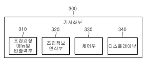
이러한, 가시화부(300)는, 도 3과 함께 참조하면, 조립 매뉴얼 입출력부(310), 조립 정보 인식부(320), 제어부(330) 및 디스플레이부(340)를 포함하여 구성된다. 3, the
조립 매뉴얼 입출력부(310)는 사용자가 저장부(200)에 저장된 조립 과정 매뉴얼의 특정 조립 단계를 선택할 수 있도록 형성된다. 그리고, 조립 매뉴얼 입출력부(310)는 사용자가 조립 과정 매뉴얼의 외부 출력을 선택할 수 있도록 형성될 수 있다. Assembly manual input and
조립 정보 인식부(320)는 실제 부품의 조립 단계를 카메라 영상으로 인식한다. The assembly
제어부(330)는 조립 과정 매뉴얼 입출력부(310)를 통하여 사용자가 선택한 특정 조립 단계의 조립 과정이 후술하는 디스플레이부(340)에 디스플레이 되도록 제어한다. 그리고, 제어부(330)는 사용자가 조립 과정 매뉴얼 입출력부(310)에서 조립 과정 매뉴얼의 외부 출력을 선택하는 경우, 외부 디스플레이 기기 즉, 노트북, 태블릿 PC, TV 등에 조립 과정 매뉴얼이 디스플레이 되도록 신호를 제어할 수 있다. 또한, 제어부(330)는 조립 정보 인식부(320)에서 인식된 실제 부품의 조립 단계에 대응하는 조립 과정 매뉴얼의 조립 단계가 디스플레이부(340)에 디스플레이 되도록 제어할 수 있다. 즉, 제어부(330)는 조립 정보 인식부(320)에서 인식된 영상을 분석하여, 실제 부품의 조립 단계에 대응하는 조립 과정 매뉴얼의 조립 단계를 검색하고, 조립 과정 매뉴얼의 조립 단계의 조립 과정이 디스플레이부에 디스플레이되도록 제어할 수 있다. 조립 정보 인식부(320) 및 제어부(330)에 의하여 실제 부품의 조립 단계를 바탕으로 다음에 조립될 부품에 대한 정보를 가시화할 수 있어, 사용자가 조립 과정에 대한 이해를 더욱 빠르게 할 수 있다.The
디스플레이부(340)는 조립 과정 매뉴얼의 3차원 입체 영상을 사용자에게 디스플레이한다. 그리고, 디스플레이부(340)는 조립 정보 인식부(320) 및 제어부(330)의 동작에 의하여, 증강 현실의 방법으로 부품 조립에 대한 안내를 사용자에게 할 수 있다.
The
이하에서는 본 발명에 따른 조립 과정 가시화 장치의 신규 생상 생성부 및 신규 재질 생성부의 동작 예시에 대하여 설명하도록 한다. Hereinafter, an operation example of the new image generating unit and the new material generating unit of the assembly process visualization apparatus according to the present invention will be described.
도 4는 본 발명에 따른 조립 과정 가시화 장치의 신규 색상 생성부에 대하여 설명하기 위한 도면이다. 도 5는 본 발명에 따른 조립 과정 가시화 장치의 신규 재질 생성부에 대하여 설명하기 위한 도면이다.
4 is a view for explaining a new color generation unit of the assembly process visualization apparatus according to the present invention. 5 is a view for explaining a new material generating unit of the assembly process visualization apparatus according to the present invention.
도 4를 참조하면, 본 발명에 따른 조립 과정 가시화 장치에서 신규 색상 생성부(121)는 서로 다른 두 색상을 갖는 제 1 색상 툴(121a) 및 제 2 색상 툴(121b)의 색상 정보를 컬러 믹서(Color mixer, 121c)를 통해 읽는다. 이 때, 색상 툴은 색상을 표현할 수 있는 물감, 컬러 점토, 셀로판지 등이 될 수 있다. 그리고, 컬러 믹서(121c)는 제 1 색상 툴(121a) 및 제 2 색상 툴(121b)의 색상 정보를 혼합하여 컬러 휠(Color wheel, 121d)에 따라 새로운 색상 디지털 정보를 생성할 수 있다. 이렇게, 새로 생성된 색상 디지털 정보는 각 부품에 적용될 수 있다. Referring to FIG. 4, in the assembling process visualization apparatus according to the present invention, the
도 5를 참조하면, 본 발명에 따른 조립 과정 가시화 장치에서 신규 재질 생성부(122)는 서로 다른 두 재질을 갖는 제 1 재질 툴(122a) 및 제 2 재질 툴(122b)의 재질 정보를 재질 믹서(Material Mixer, 122c)를 통해 읽는다. 그리고, 재질 믹서(122c)는 제 1 재질 툴(122a) 및 제 2 재질 툴(122b)의 재질 정보를 혼합하고, 쉐이더 코드(Shader code)로 재질 휠(Material wheel, 122d)에 의한 새로운 재질 디지털 정보를 생성할 수 있다. 이렇게, 새로 생성된 재질 디지털 정보는 각 부품에 적용될 수 있다.
Referring to FIG. 5, in the assembling process visualization apparatus according to the present invention, the
이하에서는 본 발명에 따른 조립 과정 가시화 방법에 대하여 설명하도록 한다. Hereinafter, the assembly process visualization method according to the present invention will be described.
도 6은 본 발명에 따른 조립 과정 가시화 방법을 설명하기 위한 플로우챠트이다. 도 7은 본 발명에 따른 조립 과정 가시화 방법의 조립 과정 매뉴얼 저작 단계를 설명하기 위한 플로우챠트이다. 도 8은 본 발명에 따른 조립 과정 가시화 방법의 애니메이션 동작 표현 단계를 설명하기 위한 플로우챠트이다.
6 is a flowchart illustrating a method of visualizing an assembly process according to the present invention. 7 is a flowchart illustrating an assembly process manual authoring step of the assembly process visualization method according to the present invention. 8 is a flowchart for explaining an animation motion representation step of the assembly process visualization method according to the present invention.
도 6을 참조하면, 본 발명에 따른 조립 과정 가시화 방법은 조립 과정 매뉴얼 저작 단계(S100), 조립 과정 매뉴얼 저장 단계(S200) 및 조립 과정 매뉴얼 가시화 단계(S600)를 포함하여 이루어진다. 또한, 본 발명에 따른 조립 과정 가시화 방법은 조립 과정 매뉴얼 선택 단계(S300), 조립 정보 인식 단계(S400) 및 조립 과정 매뉴얼 검색 단계(S500)를 더 포함하여 이루어질 수 있다.
Referring to FIG. 6, the assembly process visualization method according to the present invention includes an assembly process manual authoring step S100, an assembly process manual storage step S200, and an assembly process manual visualization step S600. In addition, the assembly process visualization method according to the present invention may further comprise an assembly process manual selection step (S300), assembly information recognition step (S400) and assembly process manual search step (S500).
조립 과정 매뉴얼 저작 단계(S100)는 다수개의 부품을 조립하여 완성품이 완성되는 조립 과정을, 단계별로 3차원 입체 영상으로 모델링하여 조립 과정 매뉴얼을 저작하는 단계이다. Assembly process manual authoring step (S100) is a step of authoring the assembly process manual by modeling a three-dimensional three-dimensional image of the assembly process to complete the finished product by assembling a plurality of parts.
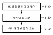
이러한, 조립 과정 매뉴얼 저작 단계(S100)는, 도 7과 함께 참조하면, 3D 모델링 데이터 제작 단계(S110), 색상/재질 표현 단계(S120) 및 애니메이션 동작 표현 단계(S130)를 포함하여 이루어진다. The assembly process manual authoring step (S100), referring to FIG. 7, includes a 3D modeling data production step (S110), a color / material representation step (S120), and an animation motion representation step (S130).
3D 모델링 데이터 제작 단계(S110)는 다수개의 부품의 3차원 기하 정보를 분석하여, 3차원 모델링 데이터를 제작하는 단계이다. 그리고, 3D 모델링 데이터 제작 단계(S110)는 카메라 영상을 통한 형상 검출(Shape detection) 기반의 셰이프 모델링(Shape modeling), 스케치 기반의 셰이프 모델링, 3차원 데이터의 기반이 되는 예제 데이터를 가지고 이를 블록 형태로 붙이는 방식의 탬플릿 기반의 모델링 및 기하 정보에 무늬를 표현하기 위한 방법인 클립아트 기반의 텍스쳐 매핑 중의 적어도 하나의 방법을 통해 이루어질 수 있다. 3D modeling data production step (S110) is a step of analyzing the three-dimensional geometric information of a plurality of parts, to produce three-dimensional modeling data. In addition, the 3D modeling data production step (S110) has a block detection-based shape modeling (Shape modeling), a sketch-based shape modeling, the example data that is the basis of the three-dimensional data based on the shape detection (camera image) Template-based modeling based on the pasting method, and at least one of the clip art-based texture mapping, which is a method for expressing a pattern in geometric information.
색상/재질 표현 단계(S120)는 3D 모델링 데이터 제작 단계(S110)를 통해 제작된 다수개의 부품의 3차원 모델링 데이터에 색상 및 재질을 표현하는 단계이다. The color / material expression step S120 is a step of expressing colors and materials in the 3D modeling data of a plurality of parts manufactured through the 3D modeling data production step S110.
애니메이션 동작 표현 단계(S130)는 색상/재질 표현 단계를 통해 색상 및 재질이 표현된 다수개의 부품의 3차원 모델링 데이터에, 다수개의 부품을 통해 완성품을 완성하는 조립 동작에 대한 움직임 데이터를 포함시켜 조립 과정 매뉴얼을 저작하는 단계이다. Animation motion expression step (S130) is assembled by including the motion data for the assembly motion to complete the finished product through a plurality of parts in the three-dimensional modeling data of a plurality of parts expressed color and material through the color / material representation step The process of authoring a manual.
이러한, 애니메이션 동작 표현 단계(S130)는, 도 8과 함께 참조하면, 제한 조건 정의 단계(S131), 스냅 드래깅 정의 단계(S132), 제스처 기반 동작 정의 단계(S133) 및 부품 접착 방법 정의 단계(S134)를 포함하여 이루어질 수 있다. Such an animation motion expression step (S130), referring to FIG. 8, defines a constraint condition step (S131), a snap dragging definition step (S132), a gesture-based motion definition step (S133), and a part bonding method definition step (S134). It can be made, including).
제한 조건 정의 단계(S131)는 다수개의 부품 간의 결합 관계 정보를 바탕으로, 다수개의 부품이 기 정하여진 영역 내에서만 상호 결합하도록 부품 간의 결합 제한 조건을 정의하는 단계이다. Constraint defining step (S131) is a step of defining a coupling constraint between components such that the plurality of components are mutually coupled only within a predetermined region based on the coupling relationship information between the plurality of components.
스냅 드래깅 정의 단계(S132)는 다수개의 부품 간의 결합 관계 정보를 바탕으로, 다수개의 부품이 기 정하여진 조립 포인트 및 조립 라인을 따라서만 상호 결합되도록 하는 방식에 대하여 정의하는 단계이다. The snap dragging definition step S132 is a step of defining a method of allowing a plurality of parts to be coupled to each other only along a predetermined assembly point and an assembly line based on the coupling relationship information between the plurality of parts.
제스처 기반 동작 정의 단계(S133)는 다수개의 부품을 통해 완성품을 완성하는 조립 동작에 대한 움직임 데이터를 단계별로 정의하는 단계이다. Gesture-based motion definition step (S133) is a step of defining the motion data for the assembly motion to complete the finished product through a plurality of parts step by step.
부품 접착 방법 정의 단계(S134)는 부품 간의 접착 방법에 따라, 서로 다르게 부품 간의 접착 부위를 표현하는 단계이다.
Defining a part bonding method step (S134) is a step of expressing the bonding portion between the parts differently, according to the method of bonding between the parts.
조립 과정 매뉴얼 저장 단계(S200)는 조립 과정 매뉴얼 저작 단계(S100)에서 저작된 조립 과정 매뉴얼을 저장부에 저장하는 단계이다.
Assembly process manual storage step (S200) is a step of storing the assembly process manual written in the assembly process manual authoring step (S100) to the storage unit.
조립 과정 매뉴얼 선택 단계(S300)는 사용자가 조립 과정 매뉴얼에서 특정 조립 단계를 선택하는 단계이다.
Assembly process manual selection step (S300) is a step in which the user selects a specific assembly step in the assembly process manual.
조립 정보 인식 단계(S400)는 실제 부품의 조립 단계를 카메라 영상으로 인식하는 단계이다.
Assembly information recognition step (S400) is a step of recognizing the assembly step of the actual part as a camera image.
조립 과정 매뉴얼 검색 단계(S500)는 조립 정보 인식 단계(S400)에서 인식된 영상을 분석하여, 실제 부품의 조립 단계에 대응하는 조립 과정 매뉴얼의 조립 단계를 검색하는 단계이다.
Assembly process manual search step (S500) is a step of searching for the assembly step of the assembly process manual corresponding to the assembly step of the actual component by analyzing the image recognized in the assembly information recognition step (S400).
조립 과정 매뉴얼 가시화 단계(S600)는 3차원 입체 영상의 조립 과정 매뉴얼을 사용자에게 단계별로 가시화하는 단계이다. 그리고, 조립 과정 매뉴얼 가시화 단계(S600)는 사용자가 조립 과정 매뉴얼 선택 단계(S300)에서 선택한 특정 조립 단계의 조립 과정이 사용자에게 디스플레이 되도록 이루어질 수 있다. 또한, 조립 과정 매뉴얼 가시화 단계(S600)는 조립 과정 매뉴얼 검색 단계(S500)에서 검색된 실제 부품의 조립 단계에 대응하는 조립 과정 매뉴얼의 조립 단계를 증강 현실의 방법으로 디스플레이 할 수 있다. 또한, 조립 과정 매뉴얼 가시화 단계(S600)는 사용자의 선택에 따라 조립 과정 매뉴얼이 외부 디스플레이 기기에 디스플레이 되도록 이루어질 수 있다.
The assembly process manual visualization step (S600) is a step of visualizing the assembly process manual of the 3D stereoscopic image to the user step by step. In addition, the assembly process manual visualization step S600 may be performed such that the assembly process of the specific assembly step selected by the user in the assembly process manual selection step S300 is displayed to the user. In addition, the assembly process manual visualization step (S600) may display the assembly step of the assembly process manual corresponding to the assembly step of the actual component found in the assembly process manual search step (S500) in an augmented reality method. In addition, the assembly process manual visualization step (S600) may be made so that the assembly process manual is displayed on the external display device according to the user's selection.
이상에서와 같이 본 발명에 따른 조립 과정 가시화 장치 및 방법은 상기한 바와 같이 설명된 실시예들의 구성과 방법이 한정되게 적용될 수 있는 것이 아니라, 상기 실시예들은 다양한 변형이 이루어질 수 있도록 각 실시예들의 전부 또는 일부가 선택적으로 조합되어 구성될 수도 있다.As described above, the apparatus and method for assembling the visualization process according to the present invention is not limited to the configuration and method of the embodiments described as described above, but the embodiments may be modified in various ways. All or part may be optionally combined.
1000; 조립 과정 가시화 장치
100; 저작부 110; 3D 모델링 데이터 제작부
120; 색상/재질 표현부 130; 애니메이션 동작 표현부
200; 저장부
300; 가시화부 310; 조립 과정 매뉴얼 입출력부
320; 조립 정보 인식부 330; 제어부
340; 디스플레이부1000; Assembly process visualization device
100;
120; Color /
200; Storage
300;
320; Assembly
340; Display part
Claims (20)
상기 저작부에서 저작된 상기 조립 과정 매뉴얼을 저장하는 저장부; 및
상기 저장부에 저장된 상기 조립 과정 매뉴얼을 사용자에게 단계별로 가시화하는 가시화부를 포함하는 것을 특징으로 하는 조립 과정 가시화 장치.An authoring unit authoring an assembly process manual by assembling a plurality of parts to model the assembly process in which a finished product is completed by three-dimensional stereoscopic image step by step;
A storage unit for storing the assembly process manual written in the authoring unit; And
And a visualization unit configured to visualize the assembly process manual stored in the storage unit step by step.
상기 가시화부는
실제 부품의 조립 단계를 영상으로 인식하는 조립 정보 인식부;
상기 조립 과정 매뉴얼을 상기 사용자에게 디스플레이하는 디스플레이부; 및
상기 조립 정보 인식부에서 인식된 상기 영상을 분석하여, 상기 실제 부품의 조립 단계에 대응하는 상기 조립 과정 매뉴얼의 조립 단계를 검색하고, 상기 조립 과정 매뉴얼의 상기 조립 단계의 상기 조립 과정이 상기 디스플레이부에 디스플레이되도록 제어하는 제어부를 포함하는 것을 특징으로 하는 조립 과정 가시화 장치.The method according to claim 1,
The visualization unit
An assembly information recognizing unit configured to recognize an assembly step of the actual component as an image;
A display unit configured to display the assembly process manual to the user; And
The assembly process of the assembly process manual corresponding to the assembly process of the actual component is searched by analyzing the image recognized by the assembly information recognition unit, and the assembly process of the assembly process of the assembly process manual is performed by the display unit. Assembly process visualization apparatus comprising a control unit for controlling to be displayed on.
상기 가시화부는
상기 사용자가 상기 저장부에 저장된 상기 조립 과정 매뉴얼의 조립 단계를 선택할 수 있도록 형성되는 조립 과정 매뉴얼 입출력부;
상기 조립 과정 매뉴얼을 상기 사용자에게 디스플레이하는 디스플레이부; 및
상기 조립 과정 매뉴얼 입출력부를 통하여 상기 사용자가 선택한 상기 조립 단계의 상기 조립 과정이 상기 디스플레이부에 디스플레이 되도록 제어하는 제어부를 포함하는 것을 특징으로 하는 조립 과정 가시화 장치.The method according to claim 1,
The visualization unit
An assembly process manual input / output unit configured to allow the user to select an assembly step of the assembly process manual stored in the storage unit;
A display unit configured to display the assembly process manual to the user; And
And a control unit for controlling the assembly process of the assembly step selected by the user to be displayed on the display unit through the assembly process manual input / output unit.
상기 조립 과정 매뉴얼 입출력부는 상기 사용자가 상기 조립 과정 매뉴얼의 외부출력을 선택할 수 있도록 형성되고,
상기 제어부는 상기 사용자가 상기 조립 과정 매뉴얼 입출력부에서 상기 외부출력을 선택하는 경우, 상기 조립 과정 매뉴얼이 외부 디스플레이 기기에 디스플레이 되도록 제어하는 것을 특징으로 하는 조립 과정 가시화 장치.The method according to claim 3,
The assembly process manual input and output unit is formed so that the user can select the external output of the assembly process manual,
And the control unit controls the assembly process manual to be displayed on an external display device when the user selects the external output from the assembly process manual input / output unit.
상기 저작부는
다수개의 상기 부품의 3차원 기하 정보를 분석하여, 다수개의 상기 부품의 3차원 모델링 데이터를 제작하는 3D 모델링 데이터 제작부;
다수개의 상기 부품의 상기 3차원 모델링 데이터에 색상 및 재질을 표현하는 색상/재질 표현부; 및
상기 색상/재질 표현부를 통해 색상 및 재질이 표현된 다수개의 상기 부품의 상기 3차원 모델링 데이터에, 다수개의 상기 부품을 통해 상기 완성품을 완성하는 조립 동작에 대한 움직임 데이터를 포함시켜, 상기 조립 과정 매뉴얼을 저작하는 애니메이션 동작 표현부를 포함하는 것을 특징으로 하는 조립 과정 가시화 장치.The method according to claim 1,
The authoring unit
A 3D modeling data production unit configured to analyze 3D geometric information of a plurality of parts and to produce 3D modeling data of the plurality of parts;
A color / material representation unit expressing a color and a material in the three-dimensional modeling data of a plurality of parts; And
The assembly process manual includes motion data on an assembly operation for completing the finished product through the plurality of parts in the three-dimensional modeling data of the plurality of parts in which color and material are expressed through the color / material expression unit. Assembly process visualization apparatus comprising an animation motion representation for authoring.
상기 저장부는 상기 부품의 상기 3차원 모델링 데이터에 적용하기 위한 색상 및 재질의 데이터를 더 저장하고 있으며,
상기 색상/재질 표현부는
서로 다른 두 색상을 혼합한 색상에 대한 디지털 데이터 값을 생성하여 상기 저장부에 저장하는 신규 색상 생성부; 및
상기 저장부에 저장된 상기 색상 및 상기 재질의 데이터를 바탕으로 상기 부품의 색상 및 재질을 정의하는 색상/재질 정의부를 포함하는 것을 특징으로 하는 조립 과정 가시화 장치.The method according to claim 5,
The storage unit further stores data of color and material for applying to the three-dimensional modeling data of the component,
The color / material expression unit
A new color generator for generating digital data values for a color of two different colors and storing them in the storage unit; And
And a color / material definition unit defining a color and a material of the part based on the data of the color and the material stored in the storage unit.
상기 저장부는 상기 부품의 상기 3차원 모델링 데이터에 적용하기 위한 색상 및 재질의 데이터를 더 저장하고 있으며,
상기 색상/재질 표현부는
서로 다른 두 재질을 혼합한 재질에 대한 디지털 데이터 값을 생성하여 상기 저장부에 저장하는 신규 재질 생성부; 및
상기 저장부에 저장된 상기 색상 및 상기 재질의 데이터를 바탕으로 상기 부품의 색상 및 재질을 정의하는 색상/재질 정의부를 포함하는 것을 특징으로 하는 조립 과정 가시화 장치.The method according to claim 5,
The storage unit further stores data of color and material for applying to the three-dimensional modeling data of the component,
The color / material expression unit
A new material generation unit generating digital data values for materials in which two different materials are mixed and storing the digital data values in the storage unit; And
And a color / material definition unit defining a color and a material of the part based on the data of the color and the material stored in the storage unit.
상기 애니메이션 동작 표현부는
다수개의 상기 부품 간의 결합 관계 정보를 바탕으로, 다수개의 상기 부품이 기 정하여진 영역 내에서 상호 결합하도록 상기 부품 간의 결합 제한 조건을 정의하는 제한 조건 정의부;
다수개의 상기 부품 간의 결합 관계 정보를 바탕으로, 다수개의 상기 부품이 기 정하여진 조립 포인트 및 조립 라인을 따라 상호 결합하도록 하는 방식에 대하여 정의하는 스냅 드래깅 정의부; 및
다수개의 상기 부품을 통해 상기 완성품을 완성하는 상기 조립 과정에 대한 움직임 데이터를 단계별로 정의하는 제스처 기반 동작 정의부를 포함하는 것을 특징으로 하는 조립 과정 가시화 장치.The method according to claim 5,
The animation motion expression unit
A constraint defining unit that defines a coupling constraint between the parts based on the coupling relationship information between the plurality of parts, such that the plurality of parts are coupled to each other within a predetermined area;
A snap dragging definition unit defining a method of allowing the plurality of parts to be coupled to each other along a predetermined assembly point and an assembly line based on the coupling relationship information between the plurality of parts; And
Assembly process visualization device comprising a gesture-based motion definition unit for defining the step-by-step movement data for the assembly process to complete the finished product through a plurality of parts.
상기 애니메이션 동작 표현부는
다수개의 상기 부품 간의 접착 방법에 따라, 서로 다르게 상기 부품 간의 접착 부위를 표현하는 접착 방법 정의부를 포함하는 것을 특징으로 하는 조립 과정 가시화 장치.The method according to claim 5,
The animation motion expression unit
And a bonding method definition unit for differently representing the bonding portions between the components according to the bonding method between the plurality of components.
상기 3D 모델링 데이터 제작부는
카메라 영상을 통한 형상 검출 기반의 셰이프 모델링, 스케치 기반의 셰이프 모델링, 템플릿 기반의 모델링 및 클립아트 기반의 텍스쳐 매핑 중의 적어도 하나의 방법을 통해 상기 3차원 모델링 데이터를 제작하는 것을 특징으로 하는 조립 과정 가시화 장치. The method according to claim 5,
The 3D modeling data production unit
Assembly process visualization comprising producing the three-dimensional modeling data through at least one method of shape detection based shape detection, sketch based shape modeling, template based modeling, and clip art based texture mapping using a camera image Device.
상기 조립 과정 매뉴얼 저작 단계에서 저작된 상기 조립 과정 매뉴얼을 저장부에 저장하는 조립 과정 매뉴얼 저장 단계; 및
상기 매뉴얼 저장 단계에서 저장된 상기 조립 과정 매뉴얼을 사용자에게 단계별로 가시화하는 조립 과정 매뉴얼 가시화 단계를 포함하는 것을 특징으로 하는 조립 과정 가시화 방법.An assembly process manual authoring step of authoring an assembly process manual by assembling a plurality of parts and modeling an assembly process in which a finished product is completed by a three-dimensional stereoscopic image step by step;
An assembly process manual storage step of storing the assembly process manual written in the assembly process manual authoring step in a storage unit; And
And an assembly process manual visualization step of visualizing the assembly process manual stored in the manual storing step by step.
실제 부품의 조립 단계를 영상으로 인식하는 조립 정보 인식 단계; 및
상기 조립 정보 인식 단계에서 인식된 상기 영상을 분석하여, 상기 실제 부품의 조립 단계에 대응하는 상기 조립 과정 매뉴얼의 조립 단계를 검색하는 조립 과정 매뉴얼 검색 단계를 더 포함하며,
상기 조립 과정 매뉴얼 가시화 단계는 상기 조립 정보 검색 단계에서 검색된 상기 조립 과정 매뉴얼의 상기 조립 단계의 상기 조립 과정을 디스플레이 하는 것을 특징으로 하는 조립 과정 가시화 방법.The method of claim 11,
An assembly information recognizing step of recognizing an assembly step of the actual component as an image; And
An assembly process manual search step of searching for an assembly step of the assembly process manual corresponding to the assembling step of the actual component by analyzing the image recognized in the assembly information recognition step,
And said assembling process manual visualization step displays said assembling process of said assembling step of said assembling process manual retrieved in said assembling information searching step.
상기 조립 과정 매뉴얼 저작 단계는
다수개의 상기 부품의 3차원 기하 정보를 분석하여, 다수개의 상기 부품의 3차원 모델링 데이터를 제작하는 3D 모델링 데이터 제작 단계;
다수개의 상기 부품의 상기 3차원 모델링 데이터에 색상 및 재질을 표현하는 색상/재질 표현 단계; 및
상기 색상/재질 표현 단계를 통해 색상 및 재질이 표현된 다수개의 상기 부품의 상기 3차원 모델링 데이터에, 다수개의 상기 부품을 통해 상기 완성품을 완성하는 조립 동작에 대한 움직임 데이터를 포함시켜, 상기 조립 과정 매뉴얼을 저작하는 애니메이션 동작 표현 단계를 포함하는 것을 특징으로 하는 조립 과정 가시화 방법. The method of claim 11,
The assembly process manual authoring step
3D modeling data manufacturing step of analyzing three-dimensional geometric information of a plurality of parts, to produce three-dimensional modeling data of the plurality of parts;
A color / material representation step of expressing a color and a material in the three-dimensional modeling data of a plurality of parts; And
The assembly process by including the movement data for the assembly operation for completing the finished product through the plurality of parts in the three-dimensional modeling data of the plurality of parts expressed color and material through the color / material representation step, Assembly method visualization method comprising the step of authoring animation motions manual.
상기 색상/재질 표현 단계는
서로 다른 두 색상을 혼합한 색상에 대한 디지털 데이터 값을 생성하여 상기 부품의 상기 3차원 모델링 데이터에 적용할 수 있는 것을 특징으로 하는 조립 과정 가시화 방법.The method according to claim 13,
The color / material presentation step
And generating digital data values for colors in which two different colors are mixed and applying them to the three-dimensional modeling data of the part.
상기 색상/재질 표현 단계는
서로 다른 두 재질을 혼합한 재질에 대한 디지털 데이터 값을 생성하여 상기 부품의 상기 3차원 모델링 데이터에 적용할 수 있는 것을 특징으로 하는 조립 과정 가시화 방법.The method according to claim 13,
The color / material presentation step
Assembly method for visualizing the assembly process, characterized in that it is possible to generate a digital data value for a material mixed with two different materials to be applied to the three-dimensional modeling data of the part.
상기 애니메이션 동작 표현 단계는
다수개의 상기 부품간의 결합 관계 정보를 바탕으로, 다수개의 상기 부품이 기 정하여진 영역 내에서 상호 결합하도록 상기 부품 간의 결합 제한 조건을 정의하는 제한 조건 정의 단계;
다수개의 상기 부품 간의 결합 관계 정보를 바탕으로, 다수개의 상기 부품이 기 정하여진 조립 포인트 및 조립 라인을 따라 상호 결합되도록 하는 방식에 대하여 정의하는 스냅 드래깅 정의 단계; 및
다수개의 상기 부품을 통해 상기 완성품을 완성하는 조립 동작에 대한 움직임 데이터를 단계별로 정의하는 제스처 기반 동작 정의 단계를 포함하는 것을 특징으로 하는 조립 과정 가시화 방법.The method according to claim 13,
The animation motion representation step
A constraint defining step of defining coupling constraints between the components based on the coupling relationship information between the plurality of components, such that the plurality of components are mutually coupled within a predetermined area;
A snap dragging defining step of defining a manner of allowing the plurality of parts to be coupled to each other along a predetermined assembly point and an assembly line based on the coupling relationship information between the plurality of parts; And
And a gesture-based motion definition step of defining motion data for an assembly motion for completing the finished product through a plurality of parts in stages.
상기 애니메이션 동작 표현 단계는
다수개의 상기 부품 간의 접착 방법에 따라, 서로 다르게 상기 부품 간의 접착 부위를 표현하는 부품 접착 방법 정의 단계를 포함하는 것을 특징으로 하는 조립 과정 가시화 방법. The method according to claim 13,
The animation motion representation step
According to the method of bonding between the plurality of parts, the assembly process visualization method characterized in that it comprises a step of defining a part bonding method to represent the bonding portion between the parts differently.
상기 3D 모델링 데이터 제작 단계는
카메라 영상을 통한 형상 검출 기반의 셰이프 모델링, 스케치 기반의 셰이프 모델링, 템플릿 기반의 모델링 및 클립아트 기반의 텍스쳐 매핑 중의 적어도 하나의 방법을 통해 상기 3차원 모델링 데이터를 제작하는 것을 특징으로 하는 조립 과정 가시화 방법.The method according to claim 13,
The 3D modeling data production step
Assembly process visualization comprising producing the three-dimensional modeling data through at least one method of shape detection based shape detection, sketch based shape modeling, template based modeling, and clip art based texture mapping using a camera image. Way.
상기 사용자가 상기 조립 과정 매뉴얼의 단계를 선택하는 조립 과정 매뉴얼 선택 단계를 더 포함하고,
상기 조립 과정 매뉴얼 가시화 단계는 상기 사용자가 선택한 상기 단계의 조립 과정이 상기 사용자에게 디스플레이 되도록 하는 것을 특징으로 하는 조립 과정 가시화 방법.The method of claim 11,
An assembly process manual selection step of the user selecting a step of the assembly process manual,
The assembly process manual visualization step of the assembly process visualization method characterized in that the assembly process of the step selected by the user is displayed to the user.
상기 조립 과정 매뉴얼 가시화 단계는
상기 사용자의 선택에 따라 상기 조립 과정 매뉴얼이 외부 디스플레이 기기에 디스플레이 되도록 하는 것을 특징으로 하는 조립 과정 가시화 방법.The method of claim 11,
The assembly process manual visualization step
Assembly method visualization method characterized in that the assembly process manual is displayed on an external display device according to the user's selection.
Priority Applications (2)
| Application Number | Priority Date | Filing Date | Title |
|---|---|---|---|
| KR1020100104135A KR20120042440A (en) | 2010-10-25 | 2010-10-25 | Apparatus and method for visualizing assembly process |
| US13/223,466 US20120100520A1 (en) | 2010-10-25 | 2011-09-01 | Assembly process visualization apparatus and method |
Applications Claiming Priority (1)
| Application Number | Priority Date | Filing Date | Title |
|---|---|---|---|
| KR1020100104135A KR20120042440A (en) | 2010-10-25 | 2010-10-25 | Apparatus and method for visualizing assembly process |
Publications (1)
| Publication Number | Publication Date |
|---|---|
| KR20120042440A true KR20120042440A (en) | 2012-05-03 |
Family
ID=45973317
Family Applications (1)
| Application Number | Title | Priority Date | Filing Date |
|---|---|---|---|
| KR1020100104135A KR20120042440A (en) | 2010-10-25 | 2010-10-25 | Apparatus and method for visualizing assembly process |
Country Status (2)
| Country | Link |
|---|---|
| US (1) | US20120100520A1 (en) |
| KR (1) | KR20120042440A (en) |
Cited By (1)
| Publication number | Priority date | Publication date | Assignee | Title |
|---|---|---|---|---|
| WO2022255582A1 (en) * | 2021-06-04 | 2022-12-08 | 광주과학기술원 | Component assembly planning device |
Families Citing this family (22)
| Publication number | Priority date | Publication date | Assignee | Title |
|---|---|---|---|---|
| US9026242B2 (en) * | 2011-05-19 | 2015-05-05 | Taktia Llc | Automatically guided tools |
| US20130117710A1 (en) * | 2011-11-03 | 2013-05-09 | Sap Ag | System and Method of Viewing Updating for Planning Item Assemblies |
| EP3964902B1 (en) | 2012-04-26 | 2024-01-03 | Shaper Tools, Inc. | Systems and methods for performing a task on a material, or locating the position of a device relative to the surface of the material |
| US9340304B2 (en) | 2013-02-28 | 2016-05-17 | The Boeing Company | Aircraft comparison system |
| US10067650B2 (en) | 2013-06-20 | 2018-09-04 | The Boeing Company | Aircraft comparison system with synchronized displays |
| US9182892B2 (en) * | 2013-02-28 | 2015-11-10 | The Boeing Company | Condition of assembly visualization system |
| US9880694B2 (en) | 2013-05-09 | 2018-01-30 | The Boeing Company | Shop order status visualization system |
| US10481768B2 (en) | 2013-04-12 | 2019-11-19 | The Boeing Company | Nonconformance identification and visualization system and method |
| US9870444B2 (en) | 2013-03-05 | 2018-01-16 | The Boeing Company | Shop order status visualization system |
| US10061481B2 (en) * | 2013-02-28 | 2018-08-28 | The Boeing Company | Methods and devices for visually querying an aircraft based on an area of an image |
| US9492900B2 (en) | 2013-03-15 | 2016-11-15 | The Boeing Company | Condition of assembly visualization system based on build cycles |
| US9110560B1 (en) | 2013-02-28 | 2015-08-18 | The Boeing Company | Shop order status visualization system |
| US9612725B1 (en) | 2013-02-28 | 2017-04-04 | The Boeing Company | Nonconformance visualization system |
| US9292180B2 (en) | 2013-02-28 | 2016-03-22 | The Boeing Company | Locator system for three-dimensional visualization |
| US20140298216A1 (en) | 2013-03-28 | 2014-10-02 | The Boeing Company | Visualization of an Object Using a Visual Query System |
| US10416857B2 (en) | 2013-05-09 | 2019-09-17 | The Boeing Company | Serial number control visualization system |
| KR101735683B1 (en) * | 2014-01-07 | 2017-05-15 | 한국전자통신연구원 | Apparatus and method for block assembly simulation of wooden building |
| CN104036092A (en) * | 2014-06-27 | 2014-09-10 | 东南大学 | Three-dimensional process model modeling method oriented to assembly process |
| US9697432B2 (en) | 2014-12-09 | 2017-07-04 | International Business Machines Corporation | Generating support instructions by leveraging augmented reality |
| JP6968700B2 (en) | 2015-05-13 | 2021-11-17 | シェイパー ツールズ, インク.Shaper Tools, Inc. | Systems, methods, and equipment for guide tools |
| US10685147B2 (en) | 2016-02-29 | 2020-06-16 | The Boeing Company | Non-conformance mapping and visualization |
| CN109643098B (en) | 2016-08-19 | 2022-06-03 | 整形工具股份有限公司 | System, method and medium for tracking use of a drilling rig |
Family Cites Families (28)
| Publication number | Priority date | Publication date | Assignee | Title |
|---|---|---|---|---|
| US4961148A (en) * | 1989-02-06 | 1990-10-02 | Chrysler Corporation | Method for preparing automotive assembly operations documents |
| JP2865828B2 (en) * | 1990-08-22 | 1999-03-08 | 株式会社日立製作所 | Method and device for displaying operation procedure |
| US6240328B1 (en) * | 1994-01-10 | 2001-05-29 | Motorola, Inc. | Manufacturing method for assembling products by generating and scheduling dynamically assembly instructions |
| US5619630A (en) * | 1994-02-28 | 1997-04-08 | Hitachi, Ltd. | Apparatus for producing exploded view and animation of assembling and method thereof |
| US6188402B1 (en) * | 1998-01-13 | 2001-02-13 | Ciena Corporation | Manufacturing control station |
| JP2000164050A (en) * | 1998-11-27 | 2000-06-16 | Sumitomo Wiring Syst Ltd | Assembling works supporting system for wire harness |
| WO2000038117A1 (en) * | 1998-12-23 | 2000-06-29 | Washington State University Research Foundation | Method and system for a virtual assembly design environment |
| US6725184B1 (en) * | 1999-06-30 | 2004-04-20 | Wisconsin Alumni Research Foundation | Assembly and disassembly sequences of components in computerized multicomponent assembly models |
| KR20020054243A (en) * | 2000-12-27 | 2002-07-06 | 오길록 | Apparatus and method of interactive model generation using multi-images |
| US6826500B2 (en) * | 2001-06-29 | 2004-11-30 | General Electric Company | Method and system for automated maintenance and training instruction generation and validation |
| US20030163219A1 (en) * | 2001-12-21 | 2003-08-28 | Flesher Robert W. | Method and system for interactive manufacturing, assembly and testing |
| JP2003223094A (en) * | 2002-01-30 | 2003-08-08 | Mitsubishi Heavy Ind Ltd | Electronic assembly procedure manual system, system and method for supporting creation of assembly procedure manual |
| JP3939189B2 (en) * | 2002-04-17 | 2007-07-04 | パナソニック コミュニケーションズ株式会社 | Information processing apparatus, product assembly process display program, and product assembly process display method |
| US20040225390A1 (en) * | 2002-05-20 | 2004-11-11 | Lsi Logic Corporation | Direct methods system for assembly of products |
| US6819965B2 (en) * | 2002-09-09 | 2004-11-16 | Kimball International, Inc. | Electronic work instruction object oriented system and method |
| JP2004288170A (en) * | 2003-03-05 | 2004-10-14 | Olympus Corp | Three-dimensional model retrieval method and system |
| JP4291321B2 (en) * | 2003-06-03 | 2009-07-08 | トヨタ自動車株式会社 | Method and system for automatically generating process animation |
| US20050058969A1 (en) * | 2003-08-18 | 2005-03-17 | Matthews Christopher James | Method and system for conveying how to replace a part using 3D computer models in animation |
| US20080259073A1 (en) * | 2004-09-23 | 2008-10-23 | Conversion Works, Inc. | System and method for processing video images |
| US8027745B1 (en) * | 2005-03-01 | 2011-09-27 | Electrical Controls, Inc. | Non-linear, animated, interactive assembly guide and method for controlling production |
| US7415152B2 (en) * | 2005-04-29 | 2008-08-19 | Microsoft Corporation | Method and system for constructing a 3D representation of a face from a 2D representation |
| US7913190B2 (en) * | 2005-07-18 | 2011-03-22 | Dassault Systèmes | Method, system and software for visualizing 3D models |
| US7995065B2 (en) * | 2005-09-23 | 2011-08-09 | Samsung Electronics Co., Ltd. | Animation reproducing apparatus and method |
| US7739221B2 (en) * | 2006-06-28 | 2010-06-15 | Microsoft Corporation | Visual and multi-dimensional search |
| KR100803216B1 (en) * | 2006-09-28 | 2008-02-14 | 삼성전자주식회사 | Method and apparatus for authoring 3d graphic data |
| JP2008219788A (en) * | 2007-03-07 | 2008-09-18 | Toshiba Corp | Stereoscopic image display device, and method and program therefor |
| WO2008134901A1 (en) * | 2007-05-08 | 2008-11-13 | Eidgenössische Technische Zürich | Method and system for image-based information retrieval |
| US8244507B2 (en) * | 2008-11-05 | 2012-08-14 | The Boeing Company | Method and apparatus for deriving associations between parts and fasteners |
-
2010
- 2010-10-25 KR KR1020100104135A patent/KR20120042440A/en not_active Application Discontinuation
-
2011
- 2011-09-01 US US13/223,466 patent/US20120100520A1/en not_active Abandoned
Cited By (2)
| Publication number | Priority date | Publication date | Assignee | Title |
|---|---|---|---|---|
| WO2022255582A1 (en) * | 2021-06-04 | 2022-12-08 | 광주과학기술원 | Component assembly planning device |
| KR20220164853A (en) * | 2021-06-04 | 2022-12-14 | 광주과학기술원 | Components fabrication scheduling apparatus |
Also Published As
| Publication number | Publication date |
|---|---|
| US20120100520A1 (en) | 2012-04-26 |
Similar Documents
| Publication | Publication Date | Title |
|---|---|---|
| KR20120042440A (en) | Apparatus and method for visualizing assembly process | |
| CN102687176B (en) | For representing the method for dynamic object | |
| KR102294134B1 (en) | Authoring tools for synthesizing hybrid slide-canvas presentations | |
| KR101323148B1 (en) | Ucr contents editor device | |
| Payne et al. | Danceon: Culturally responsive creative computing | |
| Cannavò et al. | Immersive virtual reality-based interfaces for character animation | |
| Lou | A Virtual Reality Teaching System for Graphic Design Course. | |
| CN109887097A (en) | A kind of VR content development platform and method | |
| CN107844195B (en) | Intel RealSense-based development method and system for virtual driving application of automobile | |
| Lamberti et al. | Is immersive virtual reality the ultimate interface for 3D animators? | |
| Müller et al. | Smart prototyping-improving the evaluation of design concepts using virtual reality | |
| WO2019203952A1 (en) | Systems and methods for applications of augmented reality | |
| Miranda et al. | Sketch express: A sketching interface for facial animation | |
| CN112446937A (en) | Project progress three-dimensional visualization method based on BIM technology | |
| Cannavò et al. | A visual editing tool supporting the production of 3D interactive graphics assets for public exhibitions | |
| KR100985206B1 (en) | Device for Authoring Augmented Reality, Method and System for Authoring Augmented Reality Using the Same | |
| KR20200003437A (en) | A system for coding education using generating an application for robot control | |
| US20160225194A1 (en) | Apparatus and method for creating block-type structure using sketch-based user interaction | |
| Hempe et al. | Taking the step from edutainment to eRobotics-A novel approach for an active render-framework to face the challenges of modern, multi-domain VR simulation systems | |
| Lisboa et al. | 3D virtual environments for manufacturing automation | |
| Tching et al. | IM-sgi: an interface model for shape grammar implementations | |
| Boton et al. | A metamodel to describe nD CAD visualization as coordinated multiple views | |
| Urquhart et al. | Computational design, advanced visualisation, and the changing nature of CAD | |
| Molina Morillas et al. | Extending the Digital Shadow for Industrial Robotic Arms in a Mixed Reality Environment | |
| Hirsch | Making in Time: How Timescale Impacts the Experience, Outcomes, and Expressive Opportunities of Digital Fabrication |
Legal Events
| Date | Code | Title | Description |
|---|---|---|---|
| A201 | Request for examination | ||
| E902 | Notification of reason for refusal | ||
| E601 | Decision to refuse application |