KR20120031642A - Fish belly shaped externally prestressed concrete beam - Google Patents
Fish belly shaped externally prestressed concrete beam Download PDFInfo
- Publication number
- KR20120031642A KR20120031642A KR1020100093130A KR20100093130A KR20120031642A KR 20120031642 A KR20120031642 A KR 20120031642A KR 1020100093130 A KR1020100093130 A KR 1020100093130A KR 20100093130 A KR20100093130 A KR 20100093130A KR 20120031642 A KR20120031642 A KR 20120031642A
- Authority
- KR
- South Korea
- Prior art keywords
- tension
- cross
- section
- concrete beam
- fish
- Prior art date
Links
Images


Classifications
-
- E—FIXED CONSTRUCTIONS
- E01—CONSTRUCTION OF ROADS, RAILWAYS, OR BRIDGES
- E01D—CONSTRUCTION OF BRIDGES, ELEVATED ROADWAYS OR VIADUCTS; ASSEMBLY OF BRIDGES
- E01D2/00—Bridges characterised by the cross-section of their bearing spanning structure
- E01D2/02—Bridges characterised by the cross-section of their bearing spanning structure of the I-girder type
-
- E—FIXED CONSTRUCTIONS
- E01—CONSTRUCTION OF ROADS, RAILWAYS, OR BRIDGES
- E01D—CONSTRUCTION OF BRIDGES, ELEVATED ROADWAYS OR VIADUCTS; ASSEMBLY OF BRIDGES
- E01D2101/00—Material constitution of bridges
- E01D2101/20—Concrete, stone or stone-like material
- E01D2101/24—Concrete
- E01D2101/26—Concrete reinforced
- E01D2101/28—Concrete reinforced prestressed
Landscapes
- Engineering & Computer Science (AREA)
- Architecture (AREA)
- Civil Engineering (AREA)
- Structural Engineering (AREA)
- Rod-Shaped Construction Members (AREA)
Abstract
Description
본 발명은 콘크리트 보에 관한 것으로, 보의 중앙부 높이를 크게 하고 양측 지점부 높이를 작게 하면서 보의 중앙부를 아래로 볼록하게 하여 물고기 배 모양의 어복 형상으로 함으로서 보 단면의 구조적 성능을 높이고, 프리스트레스를 위한 긴장재의 편심을 크게 하여 프리스트레스를 효율적으로 하며, 보의 지점부 단면을 작게하여 재료를 절약함에 따라 재료비의 절약으로 경제성을 높인다. 어복 형상의 콘크리트 보는 구조적 안전성과 효율성을 증대시킬 뿐만 아니라 교량이나 기타 구조물에 이 보를 설치하면 보의 하부가 유려한 곡선 형상으로 되므로 구조물의 전체적인 미관을 향상시키는 기술 분야에 관한 것이다. The present invention relates to a concrete beam, to increase the structural performance of the cross-section of the beam by increasing the height of the center portion of the beam and to reduce the height of both sides of the beam while convex the center portion of the beam to form a fish boat shape, prestressing The prestress of the tension member is increased to increase the prestress efficiency, and the cross section of the beam portion is reduced to save the material, thereby saving the material cost and increasing the economic efficiency. It is related to the technical field to improve the overall aesthetics of the structure because the bottom of the beam becomes a smooth curved shape when the beam is installed in a bridge or other structure, as well as to increase the structural safety and efficiency.
콘크리트 보 단면의 기하학적인 형상을 개량하여 긴장재의 일부 또는 전부를 보 단면의 외부에 노출되도록 설치하는 외부 긴장 방법을 적용하여 긴장재를 긴장할 때 긴장력의 손실을 줄이고 긴장재의 유지관리를 용이하게 하는 것을 특징으로 하는 외부 긴장 어복형 콘크리트 보를 제공하는데 목적이 있다.By improving the geometric shape of the concrete beam cross section, the external tension method is installed to expose some or all of the tension material to the outside of the beam cross section to reduce the loss of tension when tensioning the tension material and to facilitate the maintenance of the tension material. The purpose of the present invention is to provide an external tension fish type concrete beam.
본 발명에서 제공하는 콘크리트 보는 기본적으로 T자형 단면 형상으로 제작되는 어복형 외부 긴장 콘크리트 보에 있어서, 보의 길이 방향을 따라 중앙부의 높이는 크고 양측 지점부는 높이가 작게 형성하되, 보의 하부면이 아래로 만곡되어 물고기의 복부 형상으로 아래로 볼록하게 제작되며, 프리스트레스를 위한 긴장재의 대부분을 보 단면의 외부에 노출되도록 설치하는 것을 특징으로 한다.In the concrete beam provided in the present invention basically a fish-shaped external tension concrete beam produced in a T-shaped cross-sectional shape, the height of the central portion along the longitudinal direction of the beam is formed high and both point portions are small, but the lower surface of the beam It is bent to be convex downward to the abdominal shape of the fish, characterized in that the installation of the majority of the tension material for prestress exposed to the outside of the beam cross-section.
종래 기술에서 제공되는 콘크리트 보는 I자형 단면을 기본으로 하고 길이 방향으로 동일한 높이의 일정하게 하여 직선 형태로 하거나 보의 중앙부 높이를 작게 하여 위로 볼록하게 하고 있다(특허등록 제 10-0463310호). 또한, 보에 재하되는 사하중이나 활하중에 의해 발생되는 모멘트에 저항하도록 긴장재를 이용하여 프리스트레스를 도입하고 있으며, 프리스트레스에 의한 상향력을 키우고 하중에 저항하는 모멘트를 크게 하는 것이 구조적으로 가장 효율적이지만, 이렇게 하기 위해서는 긴장재의 앵커지점과 보의 중앙부를 통과하는 긴장재의 편심을 가능한 한 최대로 해야 함에도 불구하고 종래의 방법에서와 같이 보의 높이를 일정하게 직선 형태로 하거나 보의 중앙부 높이를 작게 하여 위로 볼록하게 하면 기하적인 제한으로 긴장재의 편심을 크게 할 수 없었다. 따라서, 재하되는 하중이 커서 이것에 저항하기 위한 프리스트레스에 의한 상향력을 크게 하기 위해 긴장재의 편심을 키우기 위해서는 보의 높이를 전체적으로 크게 해야 했으므로 보의 제작을 위한 재료비가 증가하여 비경제적이었다.Concrete beams provided in the prior art are based on an I-shaped cross section and are made of the same height in the longitudinal direction to form a straight line or to make the center height of the beam smaller and convex upward (Patent Registration No. 10-0463310). In addition, prestresses are introduced by using tension members to resist moments caused by dead or live loads on the beam, and it is structurally most efficient to increase the upward force by the prestresses and increase the moments that resist the loads. In order to maximize the eccentricity of the tension member passing through the anchor point of the tension member and the center of the beam as much as possible, the height of the beam must be kept constant in a straight line as in the conventional method, or the height of the center portion of the beam can be convex upward. The geometric limitations could not increase the tension eccentricity. Therefore, in order to increase the eccentricity of the tension member in order to increase the upward force due to the prestress to resist the large load, the height of the beam had to be increased as a whole, so the material cost for the fabrication of the beam was uneconomical.
종래의 방법에서 I자형 단면을 기본으로 하는 프리스트레스트 콘크리트 보는 긴장재를 콘크리트 단면 내에 매입하여 설치하였으며, 긴장재를 긴장할 때 긴장재가 삽입되는 쉬스관과 긴장재의 마찰로 인한 손실로 긴장력이 작아져 긴장 효율이 떨어지며, 긴장을 한 후에 쉬스관 내부를 그라우팅하여 밀폐시켜 보를 설치한 후 장시간이 지난 뒤 긴장재의 유지보수가 불가능한 실정이었다.In the conventional method, a prestressed concrete beam based on an I-shaped cross section is installed by embedding a tension member in the concrete section. After tension, the tension was not possible to maintain the tension material after a long time after installing the beam by grouting and sealing the inside of the sheath tube.
본 발명은 종래의 콘크리트 보에서 발생하는 구조적인 비효율성을 해결하기 위해 보의 중앙부 높이를 크게 하고 양측 지점부 높이를 작게 하면서 보의 중앙부를 아래로 볼록하게 하여 물고기의 배 모양의 어복형으로 함으로서, 보 단면의 성능을 개선하여 프리스트레스를 효율적으로 하고 재료를 절약하며 구조적 안전성을 증대시키면서, 교량이나 기타 구조물에 설치시 미관을 향상시킬 수 있도록 하며, 단면의 구조적인 특성을 활용하여 긴장재의 일부 또는 전부를 보 단면의 외부에 노출되도록 설치하는 외부 긴장 방법을 적용하도록 발명되었다.In order to solve the structural inefficiency that occurs in the conventional concrete beam, the present invention provides a fish boat shape by making the center portion of the beam convex downward while increasing the height of the center portion of the beam and decreasing the height of both side portions. In order to improve the aesthetics when installing on bridges or other structures, improve the prestressing efficiency, save materials, and increase structural safety by improving the performance of beam sections. It has been invented to apply an external tensioning method that installs everything so that it is exposed to the outside of the beam cross section.
본 발명의 목적은 콘크리트 보를 실시 예에 따라 T자형 또는 I자형 단면 형상으로 제작하고 보의 길이 방향을 따라 중앙부의 높이는 크고 양측 지점부는 높이를 작게 형성하여 보의 하부면이 아래로 만곡된 형상으로 볼록하게 하며 보의 길이 방향 형상을 물고기 복부 모양인 어복형으로 하여 어복 형상에 따라 긴장재를 배치하여 긴장재의 편심을 최대화함으로서 상재하중에 저항하는 프리스트레스에 의한 상향력을 최대화하면서 보의 지점부 단면을 작게하여 재료의 절감에 따른 공사비 감소에 의한 경제성을 확보할 수 있다. An object of the present invention is to produce a concrete beam in a T-shaped or I-shaped cross-sectional shape according to the embodiment and the height of the center portion along the longitudinal direction of the beam is formed in both sides of the point is small in height to form a curved bottom surface of the beam down The length of the beam is shaped like a fish abdomen, and the tension member is placed along the shape of the fish to maximize the eccentricity of the tension member, thereby maximizing the upward force due to prestress resisting the load. It is possible to secure the economical efficiency by reducing the construction cost due to the reduction of materials.
또한, 콘크리트 보에 프리스트레스를 도입하여 긴장하기 위한 위한 대부분의 긴장재는 보 단면의 외부에 노출되도록 설치하여 쉬스관의 마찰에 의한 손실을 줄여 프리스트레스의 효율성을 증대시키는 동시에 장기간 공용 후에 긴장재의 손상이나 프리스트레스의 손실에 따라 긴장재를 유지보수할 경우에 본 발명의 외부 긴장된 긴장재는 용이하게 교체 또는 재긴장할 수 있다.In addition, most tension materials for tensioning by introducing prestress to concrete beams are installed to be exposed to the outside of the beam cross section to reduce the losses due to friction of sheath pipes, thereby increasing the efficiency of prestresses and damage or prestressing stresses after long time sharing. The external tensioned tension material of the present invention can be easily replaced or retensioned when the tension material is maintained in accordance with the loss of.
상기 발명 내용뿐만 아니라, 어복형으로 곡선 형상으로 제작된 보를 이용하여 구조물을 설치하면 구조물의 하부 미관을 유려하게 향상시킬 수 있도록 하여 주는 어복형 외부 긴장 콘크리트 보를 제공한다.In addition to the above contents, the installation of the structure using a beam made of a curved shape in a fishery shape provides a fish-type external tension concrete beam that allows the lower aesthetics of the structure to be improved smoothly.
본 발명은 콘크리트 보에 관한 것으로, 보의 중앙부 높이를 크게 하고 양측 지점부 높이를 작게 하면서 보의 중앙부를 아래로 볼록하게 하여 물고기 배 모양의 어복 형상으로 함으로서, 보의 지점부 단면은 이 단면에 작용하는 지점 반력에 의한 전단력과 보를 연속화하기 위한 소정의 부모멘트에 저항하는 최적화된 형고와 단면으로 하고, 보의 중앙부 단면은 이곳에 집중되는 가장 큰 정모멘트에 저항할 수 있도록 단면을 최대한으로 하여 보 단면의 구조적 성능을 높인다. 또한 보의 중앙부 높이가 가장 높아서 프리스트레스를 위한 긴장재의 편심을 크게 할 수 있어 상재 하중에 저항하는 프리스트레스에 의한 상향력을 효과적으로 발생시켜 프리스트레스를 효율적으로 한다. 보의 지점부 단면을 작게 하고 긴장재를 효율적으로 하여 콘크리트와 긴장재 재료를 절약함에 따라 재료비의 절약으로 보의 제작비를 줄여 구조물의 건설비를 절감하여 사업의 경제성을 높인다. The present invention relates to a concrete beam, and to increase the center height of the beam and to reduce the height of both sides of the beam while convex the center portion of the beam to form a fish boat shape, the cross section of the point portion of the beam Optimized height and cross section resists shear force due to acting point reaction force and predetermined parent moment for continuity of beam, and the center cross section of the beam is made to maximize the cross section to resist the largest static moment concentrated here. Improve the structural performance of the beam cross section. In addition, since the height of the center of the beam is the highest, it is possible to increase the eccentricity of the tension member for the prestress, so that the prestress is effectively generated by generating the upward force by the prestress that resists the load. As the cross section of the point of the beam is made small and the tension material is efficiently saved, it saves the material of concrete and tension material, thereby reducing the construction cost of the beam by saving the material cost, thereby reducing the construction cost of the structure, thereby increasing the economics of the business.
어복 형상의 콘크리트 보는 구조적 안전성과 효율성을 증대시킬 뿐만 아니라 교량이나 기타 구조물에 이 보를 설치하면 보의 하부가 유려한 곡선 형상으로 되므로 구조물의 전체적인 미관을 향상시킨다.The fish-shaped concrete beams not only increase the structural safety and efficiency, but the installation of these beams on bridges or other structures improves the overall aesthetics of the structure because the lower part of the beams has a smooth curved shape.
콘크리트 보 단면의 기하학적인 형상을 개량하여 긴장재의 대부분을 보 단면의 외부에 노출되도록 설치하는 외부 긴장 방법을 적용하여 긴장재를 긴장할 때 쉬스관의 마찰 등에 의한 긴장력의 손실을 줄여서 긴장재를 절감하고, 장기간 구조물을 사용하는 과정에서 긴장재의 손상이나 긴장력의 이완 등이 발생하여 유지관리를 해야 하는 경우에, 단면의 외부에 노출된 긴장재는 잔존 긴장력의 측정이 용이하고 긴장재를 재긴장 또는 교체하는 작업 등의 유지관리를 용이하게 한다.By applying the external tension method that installs most of the tension member to the outside of the beam section by improving the geometric shape of the concrete beam section, the tension member is reduced by reducing the loss of tension due to friction of the sheath pipe when tensioning the tension member. In the case of using the structure, when the tension material is damaged or the tension force is released and maintenance is required, the tension material exposed to the outside of the cross section is easy to measure the remaining tension force and retension or replace the tension material. To facilitate maintenance.
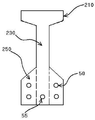
도1은 본 발명의 제1 실시 예에 의한 콘크리트 보의 지점부 단면도
도2a는 본 발명의 제1 실시 예에 의한 콘크리트 보의 변단면부 단면도
도2b는 본 발명의 제2 실시 예에 의한 콘크리트 보의 변단면부 단면도
도2c는 본 발명의 제3 실시 예에 의한 콘크리트 보의 변단면부 단면도
도3a는 본 발명의 제1 실시 예에 의한 콘크리트 보의 중앙부 단면도
도3b는 본 발명의 제2 실시 예에 의한 콘크리트 보의 중앙부 단면도
도3c는 본 발명의 제3 실시 예에 의한 콘크리트 보의 중앙부 단면도
도4는 본 발명의 제1 실시 예에 의한 콘크리트 보의 측면도
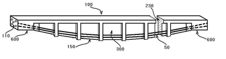
도5a는 본 발명의 제1 실시 예에 의한 콘크리트 보의 사시도
도5b는 본 발명의 제1 실시 예에 의한 콘크리트 보의 단면을 보여주는 사시도
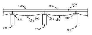
도6은 본 발명의 제1 실시 예에 의한 콘크리트 보를 적용하여 건설한 교량의 개략적인 측면도
<도면에 사용된 부호의 간단한 설명>
100 보 230 변단면부 복부 330 중앙부 복부
300 중앙부 600 지점부 150 하부면
50 노출형 긴장재 55 매립형 긴장재 800 바닥판
210 플랜지 250 콘크리트 리브 700 지지구조 1 is a cross-sectional view of a branch of a concrete beam according to a first embodiment of the present invention
Figure 2a is a cross-sectional view of the cross section of the concrete beam according to the first embodiment of the present invention
Figure 2b is a cross-sectional view of the cross section of the concrete beam according to a second embodiment of the present invention
Figure 2c is a cross-sectional view of the cross section of the concrete beam according to a third embodiment of the present invention
Figure 3a is a cross-sectional view of the central portion of the concrete beam according to the first embodiment of the present invention
Figure 3b is a cross-sectional view of the central portion of the concrete beam according to a second embodiment of the present invention
Figure 3c is a cross-sectional view of the central portion of the concrete beam according to a third embodiment of the present invention
Figure 4 is a side view of a concrete beam according to a first embodiment of the present invention
Figure 5a is a perspective view of a concrete beam according to the first embodiment of the present invention
Figure 5b is a perspective view showing a cross section of the concrete beam according to the first embodiment of the present invention
6 is a schematic side view of a bridge constructed by applying a concrete beam according to a first embodiment of the present invention;
<Brief description of symbols used in the drawings>
100
300 Center 600
50 Exposed
210
이하, 본 발명의 기술 구성을 첨부 도면을 참조하여 구체적으로 설명하며, 이들 도면에서 동일한 명칭이 부여되는 각 실시 예들의 구성 요소는 전체 도면에서 같은 부호로 표시하였다.DETAILED DESCRIPTION Hereinafter, technical configurations of the present invention will be described in detail with reference to the accompanying drawings, and components of the embodiments to which the same names are given in these drawings are denoted by the same reference numerals throughout the drawings.
도1에는 본 발명의 실시 예에 따른 콘크리트 보(100)의 지점부(600)의 단면이 도시되고, 도2a, 도2b, 도2c에는 본 발명의 실시 예에 따른 콘크리트 보(100)의 변단면부 단면의 제1 실시예, 제2 실시예 및 제3 실시예가 도시되며, 도3a, 도3b, 도3c에는 본 발명의 실시 예에 따른 콘크리트 보(100)의 중앙부(300) 단면의 제1 실시예, 제2 실시예 및 제3 실시예가 도시된다.1 is a cross-sectional view of the
도4에는 는 본 발명의 제1 실시 예에 따른 콘크리트 보(100)의 측면도가 도시되어 있다.4 is a side view of the
도5a, 도5b에는 본 발명의 제1 실시 예에 따른 콘크리트 보(100)의 사시도가 도시되어 있다.5A and 5B are perspective views of the
도6에는 는 본 발명의 실시 예에 따른 콘크리트 보(100)를 이용하여 교량을 건설한 실시 예가 도시되어 있다.6 shows an embodiment in which a bridge is constructed using the
본 발명의 외부 긴장 어복형 콘크리트 보(100)는 도2a, 도2b, 도3a, 도3b 및 도5a와 도5b에 도시되는 바와 같이, 기본적으로 T자형 단면 형상으로 제작되는 콘크리트 보(100)에 있어서, 보의 길이 방향을 따라 상기 보(100)의 중앙부 (300) 높이는 크고 양측의 지점부(600)의 높이가 작은 형상으로 변화시켜 형성하되, 보(100)의 하부면(150)이 아래로 만곡 내지는 볼록한 형태로 형성되어 물고기 배 모양의 어복 형상으로 제작되는 것을 특징으로 한다.The external tension fish-
또한, 보 단면의 내부에 매립되는 일부 긴장재(55)을 제외한 대부분의 긴장재(50)은 복부(230, 330)의 외부에 있는 리브(250, 350)에 지지하여 긴장재를 보 단면의 외부에 노출하는 것을 특징으로 한다.In addition, most of the
도2c와 도 3c에서 보이는 제3 실시 예와 같이 보(100)의 하부면(150)이 아래로 만곡 내지는 볼록한 형태로 형성되어 물고기 배 모양의 어복형으로 제작하여 본 발명의 내용을 적용하되, 보 단면의 형상은 종래와 유사하게 I형으로 하고 프리스트레스를 위한 긴장재를 보 단면의 내부에 삽입하여 긴장재의 전체를 매립형 긴장재(55)로 설치할 수 있다.As shown in the third embodiment shown in Figure 2c and Figure 3c is the
상기와 같은 구성되는 본 발명은 PSC빔(Prestressed Concrete Beam) 또는 PC빔(Precast Beam)으로 공장 또는 현장의 지상에서 도4, 도5a 및 도5b와 같이 제작이 완료된 후, 도6에 도시한 것과 같이 지지구조(700) 위에 보(100)의 양측단부(600)를 올려 놓은 다음, 이것과 일체화되도록 구조계를 형성하고 바닥판 (800)을 설치하여 필요한 구조물을 완성하게 된다.The present invention constituted as described above is a PSC beam (Prestressed Concrete Beam) or PC beam (Precast Beam) after the completion of the manufacturing process as shown in Figure 4, Figure 5a and Figure 5b on the ground of the factory or site, and shown in Figure 6 As shown above, both
이와 같이 본 발명의 콘크리트 보(100)를 적용한 구조물은 단순히 직선 형태로 표현되는 종래의 것과는 달리, 보의 하부형상(500)이 유려한 선형을 이루게 되므로 경관이 뛰어나며, 효율적인 구조로 지점부(600)와 중앙부(300)의 구조적 강성과 안전성을 확보하고 있다.As described above, the structure to which the
종래 기술에서 제공되는 I자형 단면을 기본으로 하는 콘크리트 보와 같이 길이 방향으로 동일한 높이의 일정하게 하여 직선 형태로 하거나 보의 중앙부 높이를 작게 하여 위로 오목하게 하여, 긴장재의 긴장력으로 발생하는 상재 하중에 저항하는 상향력을 크게 하기 위한 기하적인 제한으로 지점부의 긴장재와 중앙부의 긴장재 사이의 편심을 크게 하기에는 제한이 있었고, 재하되는 하중이 커서 편심을 키우기 위해서는 보의 높이를 전체적으로 크게 해야 했었으나, 본 발명의 외부 긴장 어복형 콘크리트 보(100)는 보의 길이 방향을 따라 상기 보(100)의 중앙부 (300) 높이는 크고 양측의 지점부(600)의 높이가 작은 형상으로 변화시켜 형성하되, 보(100)의 하부면(150)이 아래로 만곡 내지는 볼록한 형태로 형성되므로, 어복 형상에 따라 긴장재를 배치하면 지점부(600)에 설치되는 긴장재(50, 55)의 앵커와 보의 중앙부(300)를 통과하는 긴장재(50, 55)의 편심을 가능한 한 최대로 할 수 있어서 긴장재에 도입된 프리스트레스에 의한 상향력을 키우고 상재 하중에 저항하는 모멘트를 크게 하여 구조적인 효율성을 높인다. Like concrete beams based on I-shaped cross sections provided in the prior art, they have the same height in the longitudinal direction to form a straight line, or to reduce the center height of the beam to concave upwards, so that There was a limit to increase the eccentricity between the tension member at the point and the tension member at the center due to the geometrical limitation to increase the resistive upward force. The outer tension-
또한, 본 발명의 외부 긴장 어복형 콘크리트 보는 도2a, 도2b, 도3a, 도3b, 도5a 및 도5b에 도시되는 바와 같이 소수의 매립형 긴장재(55)만 단면의 복부(230, 330)에 매입시키고, 대부분의 노출형 긴장재(50)들은 리브(250, 350)에 지지되도록 하여 복부(230, 330)의 외부에 노출되도록 하여 긴장재를 긴장할 때 긴장재가 삽입되는 쉬스관과 긴장재의 마찰로 인한 손실로 긴장력이 작아져 긴장 효율이 떨어지는 것을 줄이고, 긴장을 한 후에도 긴장재가 복부(230, 330)의 외부에 노출되므로 구조물을 완성한 후 장시간이 지난 뒤 긴장재의 유지보수가 가능하도록 한다.In addition, as shown in FIGS. 2A, 2B, 3A, 3B, 5A, and 5B, only a few buried
Claims (2)
The tension material for introducing the prestress is supported by the ribs installed on the abdomen of the beam in parts other than the branch part, so that the tension material is installed to be exposed to the outside of the beam.
Priority Applications (1)
| Application Number | Priority Date | Filing Date | Title |
|---|---|---|---|
| KR1020100093130A KR20120031642A (en) | 2010-09-27 | 2010-09-27 | Fish belly shaped externally prestressed concrete beam |
Applications Claiming Priority (1)
| Application Number | Priority Date | Filing Date | Title |
|---|---|---|---|
| KR1020100093130A KR20120031642A (en) | 2010-09-27 | 2010-09-27 | Fish belly shaped externally prestressed concrete beam |
Publications (1)
| Publication Number | Publication Date |
|---|---|
| KR20120031642A true KR20120031642A (en) | 2012-04-04 |
Family
ID=46135038
Family Applications (1)
| Application Number | Title | Priority Date | Filing Date |
|---|---|---|---|
| KR1020100093130A KR20120031642A (en) | 2010-09-27 | 2010-09-27 | Fish belly shaped externally prestressed concrete beam |
Country Status (1)
| Country | Link |
|---|---|
| KR (1) | KR20120031642A (en) |
Cited By (5)
| Publication number | Priority date | Publication date | Assignee | Title |
|---|---|---|---|---|
| KR200471594Y1 (en) * | 2013-10-15 | 2014-03-04 | 주식회사 스틸코리아 | Self-anchored Stress Ribbon Pedestrian Bridges |
| CN103696429A (en) * | 2013-12-03 | 2014-04-02 | 中铁十三局集团第三工程有限公司 | Concrete support and fish-belly sill combined supporting system of special-shaped foundation pit and construction method |
| KR101385083B1 (en) * | 2012-04-27 | 2014-04-14 | 주식회사 포스코건설 | Prestress concrete structure providing exposed tendon and tensible force measurement method |
| CN105064200A (en) * | 2015-07-29 | 2015-11-18 | 广西交通科学研究院 | Prestressed ferroconcrete combined simply-supported beam bridge with preprocessed assembled fish-bellied truss frame and construction method of prestressed ferroconcrete combined simply-supported beam bridge |
| CN116305499A (en) * | 2023-05-18 | 2023-06-23 | 中国矿业大学(北京) | Plane layout method and device based on prestress fish belly type steel support system |
-
2010
- 2010-09-27 KR KR1020100093130A patent/KR20120031642A/en not_active Application Discontinuation
Cited By (8)
| Publication number | Priority date | Publication date | Assignee | Title |
|---|---|---|---|---|
| KR101385083B1 (en) * | 2012-04-27 | 2014-04-14 | 주식회사 포스코건설 | Prestress concrete structure providing exposed tendon and tensible force measurement method |
| KR200471594Y1 (en) * | 2013-10-15 | 2014-03-04 | 주식회사 스틸코리아 | Self-anchored Stress Ribbon Pedestrian Bridges |
| CN103696429A (en) * | 2013-12-03 | 2014-04-02 | 中铁十三局集团第三工程有限公司 | Concrete support and fish-belly sill combined supporting system of special-shaped foundation pit and construction method |
| CN103696429B (en) * | 2013-12-03 | 2015-10-28 | 中铁十三局集团第三工程有限公司 | A kind of concrete of special-shaped foundation ditch supports the combined support system and the construction method that add fish belly sill |
| CN105064200A (en) * | 2015-07-29 | 2015-11-18 | 广西交通科学研究院 | Prestressed ferroconcrete combined simply-supported beam bridge with preprocessed assembled fish-bellied truss frame and construction method of prestressed ferroconcrete combined simply-supported beam bridge |
| CN105064200B (en) * | 2015-07-29 | 2017-03-08 | 广西交通科学研究院 | The fish belly truss prestressing force steel reinforced concrete combination simply supported girder bridge of precast assembly and its construction method |
| CN116305499A (en) * | 2023-05-18 | 2023-06-23 | 中国矿业大学(北京) | Plane layout method and device based on prestress fish belly type steel support system |
| CN116305499B (en) * | 2023-05-18 | 2023-07-21 | 中国矿业大学(北京) | Plane layout method and device based on prestress fish belly type steel support system |
Similar Documents
| Publication | Publication Date | Title |
|---|---|---|
| US8627530B2 (en) | Constructing method of cable-stayed bridge and temporary cable therefor | |
| KR101178876B1 (en) | Prestressed composit rahmen bridge construdtion method | |
| KR20120031642A (en) | Fish belly shaped externally prestressed concrete beam | |
| CN210827542U (en) | Center barrel component, center barrel and tower barrel foundation | |
| KR20190119715A (en) | The composite box girder bridge structure with a support block and a tensile member, the construction method thereof | |
| KR100989811B1 (en) | Prestressed concrete slab bridge which increased in the efficiency by large decenterizing concrete block and an arch rib | |
| JP2006299631A (en) | Tower structure having non-uniform cross section, constructed by precast construction method | |
| KR101077090B1 (en) | Bridge structure of continuous PSC girder | |
| KR101546951B1 (en) | Construction method of continuous bridge using precast panel and steel box girder | |
| KR20100025161A (en) | Girder bridge connected to abutment and the construction method thereof | |
| CN101057038A (en) | Hollow prestressed concrete (HPC) girder and spliced hollow prestressed concrete girder (S-HPC) bridge construction method | |
| KR20110041145A (en) | Method for constructing continuous filled steel tube girder bridge | |
| KR20140020106A (en) | Modular wind power tower using multiple prestressing tendons | |
| KR100529518B1 (en) | The prestressed concrete beam middle point part continuous structure and the method of having used the sole plate | |
| CN109137757B (en) | Large-span corrugated steel web box girder buckling restrained structure and construction method | |
| KR100734172B1 (en) | PC Beam | |
| KR101381874B1 (en) | Side reinforced psc girder and manufacturing method thereof | |
| CN205617660U (en) | Formula of unrolling prestressed wire rope anchor system | |
| KR20160119623A (en) | PC Concrete Structure of Variable section Reinforce for Increse Stiffness with Projecting Cable and Truss Structure | |
| KR100665877B1 (en) | 2nd tension and the point part continuation method at pre-stressed concrete beam used by 2nd tension combination continuation reinforcement steel materials | |
| CN201321674Y (en) | Square plane ribbed-annual-shaped cable dome structure | |
| CN101245626A (en) | Prefabricated slab for lamination | |
| CN101245628A (en) | Prefabricated slab for lamination | |
| KR200384817Y1 (en) | Prestressed Composite Beam with Concrete Panel and Wave Type Steel Web Girder | |
| KR20120120600A (en) | Double T Concrete Girder Having Combined Prestressing and Constructing Method thereof |
Legal Events
| Date | Code | Title | Description |
|---|---|---|---|
| A201 | Request for examination | ||
| E601 | Decision to refuse application | ||
| E601 | Decision to refuse application |