KR20120008048A - Compressor having piston assembly - Google Patents
Compressor having piston assembly Download PDFInfo
- Publication number
- KR20120008048A KR20120008048A KR1020117026565A KR20117026565A KR20120008048A KR 20120008048 A KR20120008048 A KR 20120008048A KR 1020117026565 A KR1020117026565 A KR 1020117026565A KR 20117026565 A KR20117026565 A KR 20117026565A KR 20120008048 A KR20120008048 A KR 20120008048A
- Authority
- KR
- South Korea
- Prior art keywords
- fluid
- port
- compressor
- scroll
- Prior art date
Links
Images


Classifications
-
- F—MECHANICAL ENGINEERING; LIGHTING; HEATING; WEAPONS; BLASTING
- F04—POSITIVE - DISPLACEMENT MACHINES FOR LIQUIDS; PUMPS FOR LIQUIDS OR ELASTIC FLUIDS
- F04C—ROTARY-PISTON, OR OSCILLATING-PISTON, POSITIVE-DISPLACEMENT MACHINES FOR LIQUIDS; ROTARY-PISTON, OR OSCILLATING-PISTON, POSITIVE-DISPLACEMENT PUMPS
- F04C18/00—Rotary-piston pumps specially adapted for elastic fluids
- F04C18/02—Rotary-piston pumps specially adapted for elastic fluids of arcuate-engagement type, i.e. with circular translatory movement of co-operating members, each member having the same number of teeth or tooth-equivalents
- F04C18/0207—Rotary-piston pumps specially adapted for elastic fluids of arcuate-engagement type, i.e. with circular translatory movement of co-operating members, each member having the same number of teeth or tooth-equivalents both members having co-operating elements in spiral form
- F04C18/0215—Rotary-piston pumps specially adapted for elastic fluids of arcuate-engagement type, i.e. with circular translatory movement of co-operating members, each member having the same number of teeth or tooth-equivalents both members having co-operating elements in spiral form where only one member is moving
-
- F—MECHANICAL ENGINEERING; LIGHTING; HEATING; WEAPONS; BLASTING
- F04—POSITIVE - DISPLACEMENT MACHINES FOR LIQUIDS; PUMPS FOR LIQUIDS OR ELASTIC FLUIDS
- F04C—ROTARY-PISTON, OR OSCILLATING-PISTON, POSITIVE-DISPLACEMENT MACHINES FOR LIQUIDS; ROTARY-PISTON, OR OSCILLATING-PISTON, POSITIVE-DISPLACEMENT PUMPS
- F04C29/00—Component parts, details or accessories of pumps or pumping installations, not provided for in groups F04C18/00 - F04C28/00
- F04C29/12—Arrangements for admission or discharge of the working fluid, e.g. constructional features of the inlet or outlet
-
- F—MECHANICAL ENGINEERING; LIGHTING; HEATING; WEAPONS; BLASTING
- F04—POSITIVE - DISPLACEMENT MACHINES FOR LIQUIDS; PUMPS FOR LIQUIDS OR ELASTIC FLUIDS
- F04C—ROTARY-PISTON, OR OSCILLATING-PISTON, POSITIVE-DISPLACEMENT MACHINES FOR LIQUIDS; ROTARY-PISTON, OR OSCILLATING-PISTON, POSITIVE-DISPLACEMENT PUMPS
- F04C18/00—Rotary-piston pumps specially adapted for elastic fluids
- F04C18/02—Rotary-piston pumps specially adapted for elastic fluids of arcuate-engagement type, i.e. with circular translatory movement of co-operating members, each member having the same number of teeth or tooth-equivalents
- F04C18/0207—Rotary-piston pumps specially adapted for elastic fluids of arcuate-engagement type, i.e. with circular translatory movement of co-operating members, each member having the same number of teeth or tooth-equivalents both members having co-operating elements in spiral form
- F04C18/0246—Details concerning the involute wraps or their base, e.g. geometry
- F04C18/0253—Details concerning the base
- F04C18/0261—Details of the ports, e.g. location, number, geometry
-
- F—MECHANICAL ENGINEERING; LIGHTING; HEATING; WEAPONS; BLASTING
- F04—POSITIVE - DISPLACEMENT MACHINES FOR LIQUIDS; PUMPS FOR LIQUIDS OR ELASTIC FLUIDS
- F04C—ROTARY-PISTON, OR OSCILLATING-PISTON, POSITIVE-DISPLACEMENT MACHINES FOR LIQUIDS; ROTARY-PISTON, OR OSCILLATING-PISTON, POSITIVE-DISPLACEMENT PUMPS
- F04C2/00—Rotary-piston machines or pumps
- F04C2/02—Rotary-piston machines or pumps of arcuate-engagement type, i.e. with circular translatory movement of co-operating members, each member having the same number of teeth or tooth-equivalents
-
- F—MECHANICAL ENGINEERING; LIGHTING; HEATING; WEAPONS; BLASTING
- F04—POSITIVE - DISPLACEMENT MACHINES FOR LIQUIDS; PUMPS FOR LIQUIDS OR ELASTIC FLUIDS
- F04C—ROTARY-PISTON, OR OSCILLATING-PISTON, POSITIVE-DISPLACEMENT MACHINES FOR LIQUIDS; ROTARY-PISTON, OR OSCILLATING-PISTON, POSITIVE-DISPLACEMENT PUMPS
- F04C23/00—Combinations of two or more pumps, each being of rotary-piston or oscillating-piston type, specially adapted for elastic fluids; Pumping installations specially adapted for elastic fluids; Multi-stage pumps specially adapted for elastic fluids
- F04C23/008—Hermetic pumps
-
- F—MECHANICAL ENGINEERING; LIGHTING; HEATING; WEAPONS; BLASTING
- F04—POSITIVE - DISPLACEMENT MACHINES FOR LIQUIDS; PUMPS FOR LIQUIDS OR ELASTIC FLUIDS
- F04C—ROTARY-PISTON, OR OSCILLATING-PISTON, POSITIVE-DISPLACEMENT MACHINES FOR LIQUIDS; ROTARY-PISTON, OR OSCILLATING-PISTON, POSITIVE-DISPLACEMENT PUMPS
- F04C28/00—Control of, monitoring of, or safety arrangements for, pumps or pumping installations specially adapted for elastic fluids
- F04C28/24—Control of, monitoring of, or safety arrangements for, pumps or pumping installations specially adapted for elastic fluids characterised by using valves controlling pressure or flow rate, e.g. discharge valves or unloading valves
- F04C28/26—Control of, monitoring of, or safety arrangements for, pumps or pumping installations specially adapted for elastic fluids characterised by using valves controlling pressure or flow rate, e.g. discharge valves or unloading valves using bypass channels
-
- F—MECHANICAL ENGINEERING; LIGHTING; HEATING; WEAPONS; BLASTING
- F04—POSITIVE - DISPLACEMENT MACHINES FOR LIQUIDS; PUMPS FOR LIQUIDS OR ELASTIC FLUIDS
- F04C—ROTARY-PISTON, OR OSCILLATING-PISTON, POSITIVE-DISPLACEMENT MACHINES FOR LIQUIDS; ROTARY-PISTON, OR OSCILLATING-PISTON, POSITIVE-DISPLACEMENT PUMPS
- F04C29/00—Component parts, details or accessories of pumps or pumping installations, not provided for in groups F04C18/00 - F04C28/00
- F04C29/0007—Injection of a fluid in the working chamber for sealing, cooling and lubricating
-
- F—MECHANICAL ENGINEERING; LIGHTING; HEATING; WEAPONS; BLASTING
- F04—POSITIVE - DISPLACEMENT MACHINES FOR LIQUIDS; PUMPS FOR LIQUIDS OR ELASTIC FLUIDS
- F04C—ROTARY-PISTON, OR OSCILLATING-PISTON, POSITIVE-DISPLACEMENT MACHINES FOR LIQUIDS; ROTARY-PISTON, OR OSCILLATING-PISTON, POSITIVE-DISPLACEMENT PUMPS
- F04C29/00—Component parts, details or accessories of pumps or pumping installations, not provided for in groups F04C18/00 - F04C28/00
- F04C29/04—Heating; Cooling; Heat insulation
- F04C29/042—Heating; Cooling; Heat insulation by injecting a fluid
Abstract
압축기는 제1 유체 포켓 및 제2 유체 포켓을 형성하는 선회 스크롤 및 비-선회 스크롤을 포함하고 있다. 제1 포트 및 제2 포트는 비-선회 스크롤 내에 배치되어 있으며 서로 반경방향으로 이격되어 있다. 제1 포트는 제1 반경방향 위치에서 제1 유체 포켓과 연통되어 있고, 제2 포트는 제2 반경방향 위치에서 제2 유체 포켓과 연통되어 있다. 차단 장치는 포트와 유체 공급원 사이의 연통을 차단하는 제1 위치와 포트와 유체 공급원 사이의 연통을 허용하는 제2 위치 사이에서 이동가능하다. 제1 유체 포켓 및 제2 유체 포켓은 각각 제1 압력 및 제2 압력을 가지고 있다. 상기 제1 압력 및 제2 압력 중의 하나는, 상기 제1 유체 포켓 및 제2 유체 포켓 중의 적어도 하나가 상기 제1 포트 및 제2 포트 중의 적어도 하나를 통하여 유체 공급원과 연통된 후에 상기 제1 압력 및 제2 압력 중의 다른 하나에 비해 불균형적인 압력 변화를 나타낼 수 있다. 이 불균형적인 압력 변화는 선회 스크롤을 비-선회 스크롤에 대하여 가압한다.The compressor includes a pivoting scroll and a non-orbiting scroll forming a first fluid pocket and a second fluid pocket. The first port and the second port are disposed in the non-orbiting scroll and are radially spaced from each other. The first port is in communication with the first fluid pocket at the first radial position and the second port is in communication with the second fluid pocket at the second radial position. The shutoff device is movable between a first position that blocks communication between the port and the fluid source and a second position that allows communication between the port and the fluid source. The first fluid pocket and the second fluid pocket have a first pressure and a second pressure, respectively. One of the first pressure and the second pressure is the first pressure and after at least one of the first and second fluid pockets is in communication with a fluid source through at least one of the first and second ports; An unbalanced pressure change may be exhibited relative to the other of the second pressures. This unbalanced pressure change forces the swing scroll against the non-slew scroll.

Description
본 발명은 압축기에 관한 것으로서, 보다 상세하게는 용량 조절 기능을 가진 압축기에 관한 것이다.The present invention relates to a compressor, and more particularly to a compressor having a capacity adjustment function.
본 섹션은 본 발명의 개시내용에 관한 배경 지식을 제공하는데, 이 배경 지식이 반드시 종래 기술은 아니다. This section provides background on the disclosure of the present invention, which is not necessarily prior art.
냉각 시스템, 냉동 시스템, 열펌프 시스템, 그리고 다른 공조 시스템은 유체 회로를 포함하고 있는데, 이 유체 회로는 응축기, 증발기, 응축기와 증발기 사이에 배치되어 있는 팽창 장치, 그리고 응축기와 증발기 사이에서 작동 유체(예를 들면, 냉매)를 순환시키는 압축기를 가지고 있다.Cooling systems, refrigeration systems, heat pump systems, and other air conditioning systems include a fluid circuit, which includes a condenser, an evaporator, an expansion device disposed between the condenser and the evaporator, and a working fluid between the condenser and the evaporator. For example, it has a compressor for circulating a refrigerant).
압축기가 설치되어 있는 냉각 시스템, 냉동 시스템, 또는 열펌프 시스템이 요구에 따라서 냉각 및/또는 가열 효과를 효과적이며 능률적으로 제공할 수 있게 보장하기 위해서 압축기의 효율적이고 안정적인 작동이 요구된다.Efficient and stable operation of the compressor is required to ensure that the cooling system, refrigeration system, or heat pump system in which the compressor is installed can effectively and efficiently provide the cooling and / or heating effects on demand.
본 섹션은 본 발명의 개괄적인 내용을 제공하는 것으로서, 본 발명의 전체 영역 또는 본 발명의 특징 전체를 포괄적으로 개시하는 것은 아니다.
This section provides an overview of the invention and is not intended to be an exhaustive description of the entire scope of the invention or the features of the invention.
하나의 실시 형태로서, 본 발명은 압축 메카니즘, 제1 포트 및 제2 포트, 그리고 차단 장치를 포함할 수 있는 압축기를 제공한다. 압축 메카니즘은 선회 스크롤 및 비-선회 스크롤을 포함할 수 있고, 상기 선회 스크롤과 비-선회 스크롤은 서로 맞물려서 선회 스크롤과 비-선회 스크롤 사이에 이동하는 제1 유체 포켓 및 제2 유체 포켓을 형성한다. 제1 유체 포켓 및 제2 유체 포켓은 서로 각도상으로 이격되어 있으며 제1 유체 포켓 및 제2 유체 포켓이 반경방향으로 가장 안쪽 위치를 향해서 반경방향 안쪽으로 이동함에 따라 크기가 감소될 수 있다. 제1 포트 및 제2 포트는 비-선회 스크롤에서 서로 인접하게 배치될 수 있으며 제1 포트가 제1 반경방향 위치에서 제1 유체 포켓과 연통하고 제2 포트가 제2 반경방향 위치에서 제2 유체 포켓과 연통하도록 서로 반경방향으로 이격될 수 있다. 제2 반경방향 위치는 제1 반경방향 위치와 반경방향으로 가장 안쪽 위치에 대해 반경방향으로 중간에 있을 수 있다. 차단 장치는 제1 포트 및 제2 포트와 유체 공급원 사이의 유체 연통을 제한하는 제1 위치와 제1 포트 및 제2 포트와 유체 공급원 사이의 유체 연통을 허용하는 제2 위치 사이에서 이동가능하게 될 수 있다. 제1 유체 포켓 및 제2 유체 포켓은 각각 제1 유체 압력 및 제2 유체 압력을 가질 수 있다. 제1 유체 포켓과 제2 유체 포켓 중의 적어도 하나가 제1 포트와 제2 포트 중의 적어도 하나를 통하여 유체 공급원과 연통된 후에 제1 유체 압력과 제2 유체 압력 중의 하나는 제1 유체 압력과 제2 유체 압력 중의 다른 하나에 비하여 불균형적인 압력 변화를 가질 수 있다. 이 불균형적인 압력 변화는 선회 스크롤을 비-선회 스크롤에 대하여 가압할 수 있다.
In one embodiment, the present invention provides a compressor that may include a compression mechanism, a first port and a second port, and a shutoff device. The compression mechanism may include pivoting scrolls and non-orbiting scrolls, the pivoting scrolls and the non-orbiting scrolls engaging each other to form a first fluid pocket and a second fluid pocket that move between the pivoting scroll and the non-orbiting scroll. . The first fluid pocket and the second fluid pocket are angularly spaced from each other and may be reduced in size as the first fluid pocket and the second fluid pocket move radially inward toward the innermost position in the radial direction. The first port and the second port may be disposed adjacent to each other in the non-orbiting scroll, the first port communicating with the first fluid pocket at the first radial position and the second port at the second radial position. It can be radially spaced from each other to communicate with the pocket. The second radial position may be radially intermediate with respect to the first radial position and the radially innermost position. The blocking device may be movable between a first position that restricts fluid communication between the first port and the second port and the fluid source and a second position that permits fluid communication between the first port and the second port and the fluid source. Can be. The first fluid pocket and the second fluid pocket may have a first fluid pressure and a second fluid pressure, respectively. After at least one of the first fluid pocket and the second fluid pocket is in communication with the fluid source through at least one of the first port and the second port, one of the first fluid pressure and the second fluid pressure is the first fluid pressure and the second fluid pressure. It may have an unbalanced pressure change compared to the other of the fluid pressures. This unbalanced pressure change can press the swing scroll against the non-slew scroll.
다른 실시 형태로서, 본 발명은 압축 메카니즘, 제1 포트 및 제2 포트, 그리고 차단 장치를 포함할 수 있는 압축기를 제공한다. 압축 메카니즘은 선회 스크롤 및 비-선회 스크롤을 포함할 수 있고, 상기 선회 스크롤과 비-선회 스크롤은 서로 맞물려서 선회 스크롤과 비-선회 스크롤 사이에 이동하는 제1 유체 포켓 및 제2 유체 포켓을 형성한다. 제1 유체 포켓 및 제2 유체 포켓은 서로 각도상으로 이격되어 있으며 제1 유체 포켓 및 제2 유체 포켓이 반경방향으로 가장 안쪽 위치를 향해서 반경방향 안쪽으로 이동함에 따라 크기가 감소될 수 있다. 제1 포트 및 제2 포트는 비-선회 스크롤에서 서로 인접하게 배치될 수 있으며 제1 포트가 제1 반경방향 위치에서 제1 유체 포켓과 연통하고 제2 포트가 제2 반경방향 위치에서 제2 유체 포켓과 연통하도록 서로 반경방향으로 이격될 수 있다. 제2 반경방향 위치는 제1 반경방향 위치와 반경방향으로 가장 안쪽 위치에 대해 반경방향으로 중간에 있을 수 있다. 차단 장치는 제1 포트 및 제2 포트와 유체 공급원 사이의 유체 연통을 제한하는 제1 위치와 제1 포트 및 제2 포트와 유체 공급원 사이의 유체 연통을 허용하는 제2 위치 사이에서 이동가능하게 될 수 있다. 제1 유체 포켓 및 제2 유체 포켓은, 제1 유체 포켓과 제2 유체 포켓 중의 적어도 하나가 제1 포트와 제2 포트 중의 적어도 하나를 통하여 유체 공급원과 연통된 후에 불균형적으로 변화하는 제1 유체 압력 및 제2 유체 압력을 각각 가질 수 있다. 제1 포켓 및 제2 포켓의 유체 압력에 있어서의 불균형적인 변화가 선회 스크롤을 비-선회 스크롤에 대하여 가압할 수 있다.
In another embodiment, the present invention provides a compressor that may include a compression mechanism, a first port and a second port, and a shutoff device. The compression mechanism may include pivoting scrolls and non-orbiting scrolls, the pivoting scrolls and the non-orbiting scrolls engaging each other to form a first fluid pocket and a second fluid pocket that move between the pivoting scroll and the non-orbiting scroll. . The first fluid pocket and the second fluid pocket are angularly spaced from each other and may be reduced in size as the first fluid pocket and the second fluid pocket move radially inward toward the innermost position in the radial direction. The first port and the second port may be disposed adjacent to each other in the non-orbiting scroll, the first port communicating with the first fluid pocket at the first radial position and the second port at the second radial position. It can be radially spaced from each other to communicate with the pocket. The second radial position may be radially intermediate with respect to the first radial position and the radially innermost position. The blocking device may be movable between a first position that restricts fluid communication between the first port and the second port and the fluid source and a second position that permits fluid communication between the first port and the second port and the fluid source. Can be. The first fluid pocket and the second fluid pocket comprise a first fluid that changes disproportionately after at least one of the first fluid pocket and the second fluid pocket is in communication with the fluid source through at least one of the first port and the second port. Pressure and second fluid pressure, respectively. An unbalanced change in fluid pressure in the first pocket and the second pocket can press the swing scroll against the non-slew scroll.
또 다른 실시 형태로서, 본 발명은 압축 메카니즘, 단일 세트의 인접한 포트, 유체 통로, 그리고 단일 차단 장치를 포함할 수 있는 압축기를 제공한다. 압축 메카니즘은 선회 스크롤 및 비-선회 스크롤을 포함할 수 있고, 상기 선회 스크롤과 비-선회 스크롤은 서로 맞물려서 선회 스크롤과 비-선회 스크롤 사이에 이동하는 복수의 유체 포켓을 형성한다. 단일 세트의 인접한 포트는 선회 스크롤과 비-선회 스크롤 중의 하나에 배치될 수 있으며 서로 반경방향으로 이격되어 있다. 각각의 포트는 상기 복수의 유체 포켓 중의 적어도 하나와 선택적으로 유체 연통될 수 있다. 유체 통로는 선회 스크롤과 비-선회 스크롤 중의 하나에 배치될 수 있으며 단일 세트의 인접한 포트와 선택적으로 유체 연통될 수 있다. 단일 차단 장치는 상기 선회 스크롤과 비-선회 스크롤 중의 하나에 배치될 수 있으며, 단일 세트의 인접한 포트가 유체 통로를 통하여 유체 공급원과 유체 연통되는 것을 차단하는 제1 위치와 단일 세트의 인접한 포트가 유체 공급원과 유체 연통되는 것을 허용하는 제2 위치 사이에서 이동가능하다. 상기 포트와 유체 공급원 사이의 유체 연통은 압축 메카니즘의 압력 분배를 불균형적으로 변화시킬 수 있다. 압력 분배에 있어서의 불균형적인 변화는 선회 스크롤을 비-선회 스크롤에 대하여 이동시킬 수 있다.
In yet another embodiment, the present invention provides a compressor that may include a compression mechanism, a single set of adjacent ports, a fluid passageway, and a single shutoff device. The compression mechanism may include pivoting scrolls and non-orbiting scrolls, the pivoting scrolls and non-orbiting scrolls meshing with each other to form a plurality of fluid pockets that move between the pivoting and non-orbiting scrolls. A single set of contiguous ports can be disposed in one of the swing scrolls and the non-slew scrolls and are radially spaced from each other. Each port may be in selective fluid communication with at least one of the plurality of fluid pockets. The fluid passageway may be disposed in one of the swinging scroll and the non-swinging scroll and may be in selective fluid communication with a single set of adjacent ports. A single blocking device may be disposed in one of the pivoting scrolls and the non-orbiting scrolls, the first position and a single set of adjacent ports being in fluid to prevent a single set of adjacent ports from being in fluid communication with the fluid source through the fluid passage. It is movable between a second position allowing fluid communication with the source. Fluid communication between the port and the fluid source can disproportionately change the pressure distribution of the compression mechanism. Unbalanced changes in pressure distribution can cause the swing scroll to move relative to the non-swivel scroll.
본 발명의 다른 적용가능한 영역은 아래에 기술되어 있는 상세한 설명으로부터 알 수 있게 된다. 상세한 설명 및 특정 실시예는 단지 예시의 목적을 위한 것이지 본 발명의 범위를 제한하기 위한 것은 아니다.Other applicable areas of the invention will be apparent from the detailed description set forth below. The detailed description and specific examples are for illustrative purposes only and are not intended to limit the scope of the invention.
본 명세서에 첨부된 도면은 단지 예시의 목적으로 제공된 것이며 결코 본 발명의 범위를 제한하기 위한 것은 아니다.
도 1은 본 발명에 따른 압축기의 단면도이고;
도 2는 도 1의 압축기의 비-선회 스크롤의 평면도이고;
도 3은 도 1의 압축기의 비-선회 스크롤 및 압축기 출력 조정 조립체의 제1 단면도이고;
도 4는 도 3의 비-선회 스크롤 및 압축기 출력 조정 조립체의 제2 단면도이고;
도 5는 도 3의 비-선회 스크롤 및 압축기 출력 조정 조립체의 사시도이고;
도 6은 도 3의 비-선회 스크롤 및 압축기 출력 조정 조립체의 제3 단면도이고;
도 7은 도 3의 비-선회 스크롤 및 압축기 출력 조정 조립체의 제4 단면도이고;
도 8은 본 발명에 따른 다른 비-선회 스크롤 및 압축기 출력 조정 조립체의 사시도이고;
도 9는 도 8의 비-선회 스크롤 및 압축기 출력 조정 조립체의 제1 단면도이고;
도 10은 도 8의 비-선회 스크롤 및 압축기 출력 조정 조립체의 제2 단면도이고;
도 11은 도 8의 비-선회 스크롤 및 압축기 출력 조정 조립체의 제3 단면도이고;
도 12는 도 8의 비-선회 스크롤 및 압축기 출력 조정 조립체의 제4 단면도이고;
도 13은 도 8의 비-선회 스크롤 및 압축기 출력 조정 조립체의 제5 단면도이고;
도 14는 도 8의 비-선회 스크롤 및 압축기 출력 조정 조립체의 제6 단면도이고;
도 15는 도 8의 비-선회 스크롤의 평면도이고;
도 16은 본 발명에 따른 제1 스크롤 배치상태를 나타내는 개략도이고;
도 17은 본 발명에 따른 제2 스크롤 배치상태를 나타내는 개략도이고;
도 18은 본 발명에 따른 제3 스크롤 배치상태를 나타내는 개략도이고;
도 19는 본 발명에 따른 제4 스크롤 배치상태를 나타내는 개략도이고;
도 20은 본 발명에 따른 대체 실시형태의 비-선회 스크롤 및 압축기 출력 조정 조립체의 제1 단면도이고;
도 21은 도 20의 비-선회 스크롤 및 압축기 출력 조정 조립체의 제2 단면도이고;
도 22 내지 도 25는 한 세트의 조절 포트가 다른 위치에 있는 상태의 도 16 내지 도 19에 도시된 것과 유사한 다양한 스크롤 배치상태의 개략도이고; 그리고
도 26 내지 도 33은 본 발명에 따른 한 세트의 조절 포트를 가지고 있는 비대칭적인 스크롤에 대한 다양한 스크롤 배치상태의 개략도이다.The drawings attached herein are provided for purposes of illustration only and are not intended to limit the scope of the invention in any way.
1 is a cross-sectional view of a compressor according to the present invention;
2 is a top view of a non-orbiting scroll of the compressor of FIG. 1;
3 is a first cross-sectional view of the non-orbiting scroll and compressor output adjustment assembly of the compressor of FIG. 1;
4 is a second cross-sectional view of the non-orbiting scroll and compressor output adjustment assembly of FIG. 3;
5 is a perspective view of the non-orbiting scroll and compressor output adjustment assembly of FIG. 3;
FIG. 6 is a third cross-sectional view of the non-orbiting scroll and compressor output adjustment assembly of FIG. 3; FIG.
FIG. 7 is a fourth cross-sectional view of the non-orbiting scroll and compressor output adjustment assembly of FIG. 3; FIG.
8 is a perspective view of another non-orbiting scroll and compressor output adjustment assembly in accordance with the present invention;
9 is a first cross-sectional view of the non-orbiting scroll and compressor output adjustment assembly of FIG. 8;
FIG. 10 is a second cross-sectional view of the non-orbiting scroll and compressor output adjustment assembly of FIG. 8; FIG.
FIG. 11 is a third cross-sectional view of the non-orbiting scroll and compressor output adjustment assembly of FIG. 8; FIG.
12 is a fourth cross-sectional view of the non-orbiting scroll and compressor output adjustment assembly of FIG. 8;
FIG. 13 is a fifth cross sectional view of the non-orbiting scroll and compressor output adjustment assembly of FIG. 8; FIG.
FIG. 14 is a sixth cross-sectional view of the non-orbiting scroll and compressor output adjustment assembly of FIG. 8; FIG.
FIG. 15 is a top view of the non-orbiting scroll of FIG. 8; FIG.
16 is a schematic diagram showing a first scroll arrangement according to the present invention;
17 is a schematic diagram showing a second scroll arrangement in accordance with the present invention;
18 is a schematic diagram showing a third scroll arrangement according to the present invention;
19 is a schematic diagram showing a fourth scroll arrangement according to the present invention;
20 is a first cross-sectional view of a non-orbiting scroll and compressor output adjustment assembly of an alternate embodiment according to the present invention;
FIG. 21 is a second cross-sectional view of the non-orbiting scroll and compressor output adjustment assembly of FIG. 20;
22-25 are schematic views of various scroll arrangements similar to those shown in FIGS. 16-19 with one set of adjustment ports in different positions; And
26-33 are schematic views of various scroll arrangements for asymmetrical scrolling with a set of adjustment ports in accordance with the present invention.
아래의 설명은 본질적으로 단지 예시적인 것이며, 본 발명, 적용예, 또는 사용법을 제한하기 위한 것은 아니다. 여러 도면에 걸쳐서 유사한 참고 번호는 유사거나 상응하는 부분을 나타낸다.The following description is merely exemplary in nature and is not intended to limit the invention, application, or usage. Like reference numerals refer to like or corresponding parts throughout the several views.
예시된 실시예는, 본 내용이 상세하게 개시되며, 당해 기술분야의 전문가에게 그 범위가 충분히 전달되도록 제공된다. 본 발명의 실시예의 충분한 이해를 돕기 위해서, 특정의 구성요소, 장치, 그리고 방법의 예와 같은 다수의 특정적인 상세한 내용을 개시한다. 특정적인 상세한 내용이 그대로 실시될 필요는 없으며, 예시된 실시예가 다양한 상이한 형태로 구현될 수 있고 본 개시내용의 범위를 제한하는 것으로 해석되어서는 않된다는 것은 당해 기술분야의 전문가에게는 자명한 사실이다. 몇 가지 예시된 실시예에서, 잘 알려진 프로세스, 잘 알려진 장치 구조, 그리고 잘 알려진 기술은 상세하게 기술되어 있지 않다.The illustrated embodiments are provided in detail so that this disclosure will be thorough, and will fully convey the scope to those skilled in the art. In order to facilitate a thorough understanding of embodiments of the present invention, numerous specific details are set forth, such as examples of specific components, devices, and methods. It is apparent to those skilled in the art that the specific details need not be practiced as such, and that the illustrated embodiments can be embodied in a variety of different forms and should not be construed as limiting the scope of the disclosure. In some illustrated embodiments, well known processes, well known device structures, and well known techniques are not described in detail.
본 명세서에 사용된 용어는 단지 특정 실시예를 기술하기 위한 것이지 본 발명을 제한하기 위한 것은 아니다. 본 명세서에 기재되어 있는 단수 형태는, 문맥상 명확하게 다른 것으로 표현되지 않으면, 복수 형태도 포함할 수 있다. "이루어지는", "포함하는", "가지고 있는" 과 같은 표현은 포괄적인 의미를 가지므로, 언급된 특징, 정수(integer), 단계, 작동, 요소(element) 및/또는 구성요소(component)의 존재를 명시하는 것이지만, 하나 이상의 다른 특징, 정수, 단계, 작동, 요소, 구성요소 및/또는 이들의 그룹의 존재 또는 부가를 배제하는 것은 아니다. The terminology used herein is for the purpose of describing particular embodiments only and is not intended to be limiting of the invention. The singular forms described herein may also include the plural forms unless the context clearly indicates otherwise. Expressions such as "consisting of", "comprising" and "having" have a broad meaning, and therefore, refer to the features, integers, steps, operations, elements and / or components mentioned. It is intended to be in existence, but not to exclude the presence or addition of one or more other features, integers, steps, acts, elements, components, and / or groups thereof.
어느 요소나 층(layer)이 다른 요소나 층에 "놓여 있는", "맞물려 있는", "연결되어 있는", 또는 "결합되어 있는" 것으로 언급되어 있는 경우에는, 어느 요소나 층이 다른 요소나 층에 직접 놓여 있거나, 맞물려 있거나, 연결되어 있거나, 결합되어 있을 수 있거나, 또는 사이에 개재하는(intervening) 요소나 층이 존재할 수 있다. 이와 대조적으로, 어떤 요소가 다른 요소나 층에 "직접 놓여 있는", "직접 맞물려 있는", "직접 연결되어 있는", 또는 "직접 결합되어 있는" 것으로 언급되어 있는 경우에는, 사이에 개재하는 요소나 층이 존재하지 않는다. 어느 요소들 사이의 관계를 기술하기 위해서 사용된 다른 용어는 유사한 방식으로 해석되어야 한다(예를 들면, "사이에" 대 "직접 사이에", "인접한" 대 "직접 인접한," 등). 본 명세서에서 "및/또는" 이라는 표현은 관련된 열거 항목 중의 어느 하나 또는 관련된 열거 항목의 하나 이상의 조합을 포함한다. When any element or layer is referred to as being "layed", "engaged", "connected", or "coupled" to another element or layer, any element or layer may be There may be elements or layers lying directly on, engaged with, connected to, joined to, or intervening in between. In contrast, when an element is referred to as being "directly", "directly engaged", "directly connected", or "directly coupled" to another element or layer, intervening elements therebetween My layer does not exist. Other terms used to describe relationships between certain elements should be interpreted in a similar manner (eg, "between" versus "directly between", "adjacent" versus "directly adjacent," etc.). The expression “and / or” herein includes any one of the associated enumeration items or one or more combinations of related enumeration items.
제1, 제2, 제3 등의 용어가 다양한 요소, 구성요소, 구역, 층 및/또는 섹션을 기술하기 위해서 본 명세서에 사용되어 있지만, 상기 요소, 구성요소, 구역, 층 및/또는 섹션이 이러한 용어에 의해 제한되는 것은 아니다. 이러한 용어는 단지 하나의 요소, 구성요소, 구역, 층 또는 섹션을 다른 요소, 구성요소, 구역, 층 또는 섹션과 구별하기 위해서 사용된다. 본 명세서에서 "제1", "제2" 와 같은 용어와 다른 숫자와 관련된 용어가 사용되는 경우에는 문맥상으로 명확하게 표현되어 있지 않는 경우에는 차례나 순서를 의미하는 것은 아니다. 따라서, 아래에 기술된 제1 요소, 제1 구성요소, 제1 구역, 제1 층 또는 제1 섹션은 예시된 실시예의 개시내용으로부터 벗어나지 않고서 제2 요소, 제2 구성요소, 제2 구역, 제2 층 또는 제2 섹션이라고 칭할 수 있다. "제1", "제2" 등의 용어는 단지 명확성을 기하기 위해서 본 명세서 전반에 걸쳐서 사용되고 있으며 청구항에 있는 유사한 용어를 제한하기 위한 것은 아니다. Although the terms first, second, third, etc. are used herein to describe various elements, components, zones, layers and / or sections, such elements, components, zones, layers and / or sections may be used. It is not limited by these terms. These terms are only used to distinguish one element, component, zone, layer or section from another element, component, zone, layer or section. In the present specification, when terms related to numbers other than the terms “first” and “second” are used, they do not mean the order or the order unless they are expressly expressed in context. Accordingly, the first element, first component, first zone, first layer, or first section described below may be used to control the second element, second component, second zone, first, and the like without departing from the disclosure of the illustrated embodiment. It may be referred to as a second layer or a second section. Terms such as "first", "second", etc. are used throughout this specification for clarity only and are not intended to limit similar terminology in the claims.
"내측", "외측", "밑(beneath)", "아래(below)", "하부", "위", "상부" 등과 같은 공간과 관련된 용어가 도면에 도시되어 있는 바와 같이 하나의 요소 또는 특징부의 다른 요소 또는 특징부에 대한 관계를 기술하기 위해 표현의 편의상 본 명세서에 사용될 수 있다. 공간과 관련된 용어는 도면에 도시되어 있는 배치상황에 부가하여 사용시나 작동시에 있어서의 장치의 여러가지 상이한 배치상황을 포함할 수 있다. 예를 들면, 도면상의 장치가 뒤집어지면, 다른 요소나 특징부의 "아래" 또는 "밑"에 있는 것으로 기술된 요소는 다른 요소나 특징부의 "위"에 배치될 수 있다. 따라서, 예를 들어 "아래" 라는 용어는 위와 아래 양자 모두를 포함할 수 있다. 장치는 다르게 배치될 수 있으며(90도 회전된 상태 또는 다른 배치 상태) 본 명세서에 사용된 공간과 관련된 표현은 이에 상응하게 해석될 수 있다.
Terms relating to space, such as "inner", "outer", "beneath", "below", "bottom", "top", "top", and the like are shown in the figures as one element. Or may be used herein for convenience of representation to describe a relationship to another element or feature of a feature. Terms relating to space may include various different arrangements of the device in use or operation in addition to the arrangements shown in the figures. For example, when the device on the drawing is turned upside down, an element described as being "below" or "below" another element or feature may be placed "above" the other element or feature. Thus, for example, the term "below" may include both above and below. The devices can be arranged differently (rotated 90 degrees or at other positions) and the representations associated with the spaces used herein can be interpreted accordingly.
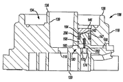
본 발명의 개시내용은 밀폐 기계, 개방 구동 기계 및 비-밀폐 기계를 포함하는 다양한 상이한 타입의 스크롤 압축기와 로터리 압축기에 포함되기에 적합하다. 예시의 목적으로, 도 1에 종단면도로 도시되어 있는 바와 같이, 압축기(10)가 로우 사이드(low-side) 타입의 밀폐 스크롤 냉각-압축기, 다시 말해서, 모터와 압축기가 밀폐 셸 내의 흡입 가스에 의해서 냉각되는 압축기로서 도시되어 있다. The present disclosure is suitable for inclusion in a variety of different types of scroll compressors and rotary compressors, including hermetic, open drive and non-sealed machines. For the purpose of illustration, as shown in longitudinal section in FIG. 1, the
도 1을 참고하면, 압축기(10)는 밀폐 셸 조립체(12), 메인 베어링 하우징 조립체(14), 모터 조립체(16), 압축 메카니즘(18), 시일 조립체(20), 냉매 배출 연결관(22), 배출 밸브 조립체(24), 흡입 가스 유입 연결관(26), 그리고 조절 조립체(27)를 포함할 수 있다. 상기 셸 조립체(12)는 메인 베어링 하우징 조립체(14), 모터 조립체(16), 그리고 압축 메카니즘(18)을 수용할 수 있다. Referring to FIG. 1, the
상기 셸 조립체(12)는 대체로 압축기 하우징을 형성할 수 있으며 원통형 셸(28), 셸 조립체의 상단부에 있는 단부 캡(30), 횡방향으로 뻗어 있는 칸막이(32), 그리고 셸 조립체의 하단부에 있는 베이스(34)를 포함할 수 있다. 단부 캡(30)과 칸막이(32)는 대체로 배출 챔버(36)를 형성할 수 있다. 배출 챔버(36)는 대체로 압축기(10)용 배출 머플러를 형성할 수 있다. 냉매 배출 연결관(22)은 단부 캡(30)의 개구(38)에서 셸 조립체(12)에 부착될 수 있다. 배출 밸브 조립체(24)는 배출 연결관(22) 내에 배치될 수 있으며 대체로 역류 상황을 방지할 수 있다. 흡입 가스 유입 연결관(26)은 개구(40)에서 셸 조립체(12)에 부착될 수 있다. 칸막이(32)는 압축 메카니즘(18)과 배출 챔버(36) 사이의 연통을 제공하는 칸막이를 관통하는 배출 통로(46)를 포함할 수 있다. The
메인 베어링 하우징 조립체(14)는 열융착(staking)과 같은 임의의 바람직한 방식으로 복수의 지점에서 셸(28)에 부착될 수 있다. 메인 베어링 하우징 조립체(14)는 메인 베어링 하우징(52), 메인 베어링 하우징(52) 내에 배치된 제1 베어링(54), 부싱(55), 그리고 파스너(57)를 포함할 수 있다. 메인 베어링 하우징(52)은 반경방향 바깥쪽으로 뻗어 있는 일련의 아암(58)을 가지고 있는 중심 몸체 부분(56)을 포함할 수 있다. 중심 몸체 부분(56)은 관통하여 형성된 개구(64)를 가지고 있는 제1 부분(60) 및 제2 부분(62)을 포함할 수 있다. 제2 부분(62)은 내부에 제1 베어링(54)을 수용할 수 있다. 제1 부분(60)은 축방향의 단부 표면에 환형상의 편평한 스러스트 베어링 표면(66)이 형성될 수 있다. 아암(58)은 아암을 관통하여 형성되어 파스너(57)를 수용하는 구멍(70)을 포함할 수 있다. The main
모터 조립체(16)는 대체로 모터 고정자(76), 회전자(78) 및 구동 샤프트(80)를 포함할 수 있다. 권선(82)이 모터 고정자(76)를 통과할 수 있다. 모터 고정자(76)는 셸(28)에 압력 끼워맞춤될 수 있다. 구동 샤프트(80)는 회전자(78)에 의해 회전구동될 수 있다. 회전자(78)는 구동 샤프트(80)에 압력 끼워맞춤될 수 있다. 구동 샤프트(80)는 평면부(86)를 가진 편심 크랭크 핀(84)을 포함할 수 있다.
압축 메카니즘(18)은 대체로 선회 스크롤(104) 및 비-선회 스크롤(106)을 포함할 수 있다. 선회 스크롤(104)은 단부 플레이트(108)를 포함할 수 있고, 단부 플레이트(108)는 단부 플레이트(108)의 상부 표면에 나선형 베인 또는 랩(110)을 가지고 있고 단부 플레이트(108)의 하부 표면에 환형상의 편평한 스러스트 표면(112)을 가지고 있다. 이 스러스트 표면(112)은 메인 베어링 하우징(52)의 환형상의 편평한 스러스트 베어링 표면(66)과 간섭할 수 있다. 원통형 허브(114)는 스러스트 표면(112)으로부터 아래쪽으로 돌출될 수 있으며 회전가능하게 배치된 구동 부싱(116)을 내장할 수 있다. 구동 부싱(116)은 크랭크 핀(84)이 구동가능하게 배치되는 내측 보어를 포함할 수 있다. 크랭크 핀 평면부(86)는 구동 부싱(116)의 내측 보어의 일부분에 있는 편평한 표면과 구동되게 결합하여 반경방향으로 유연한 구동 장치를 제공할 수 있다. 선회 스크롤(104)과 비-선회 스크롤(106) 사이의 상대 회전을 방지하기 위하여 올덤 커플링(117)이 선회 스크롤(104) 및 비-선회 스크롤(106)과 결합될 수 있다.
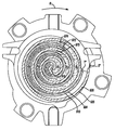
부가적으로 도 2 내지 도 5를 참고하면, 비-선회 스크롤(106)은 단부 플레이트(118)를 포함할 수 있고, 이 단부 플레이트(118)는 단부 플레이트(118)의 하부 표면에 있는 나선형 베인 또는 랩(120), 단부 플레이트(118)를 관통하여 형성되어 있는 배출 통로(119), 그리고 일련의 반경방향 바깥쪽으로 뻗어 있는 플랜지 부분(121)을 가지고 있다. 이 비-선회 스크롤(106)의 나선형 랩(120)은 선회 스크롤(104)의 나선형 랩(110)과 맞물림 결합을 형성하여, 일련의 포켓을 만들 수 있다. 비-선회 스크롤(106)의 나선형 랩(120)과 선회 스크롤(104)의 나선형 랩(110)에 의해서 만들어진 포켓은, 아래에 설명되어 있는 것과 같이, 압축 메카니즘(18)의 압축 사이클의 전체에 걸쳐서 변할 수 있다.2-5,
단부 플레이트(118)는 단부 플레이트(118)의 상부 표면에 동축의 평행한 내측 측면 벽(136) 및 외측 측면 벽(138)에 의해 형성된 환형상 리세스(134)를 포함할 수 있다. 내측 측면 벽(136)은 배출 통로(139)를 형성할 수 있다. 단부 플레이트(118)는 환형상 리세스(134) 내에 위치될 수 있는 별개의 리세스(142)를 더 포함할 수 있다. 환형상 리세스(134)로부터 격리된 챔버(147)를 형성하기 위하여 리세스(142)의 상부에 플러그(146)가 단부 플레이트(118)에 고정될 수 있다.
제1 통로(158)는 챔버(147)의 제1 부분(160)으로부터 비-선회 스크롤(106)의 외측 표면으로 단부 플레이트(118)를 관통하여 반경방향으로 형성될 수 있고, 제2 통로(162)는 챔버(147)의 제2 부분(164)으로부터 비-선회 스크롤(106)의 외측 표면으로 단부 플레이트(118)를 관통하여 반경방향으로 형성될 수 있다. 제1 통로(158)는 압축기(10)의 흡입 압력 구역과 연통될 수 있다. 제3 통로(166)(도 7)는 압축기(10)의 배출 압력 구역으로부터 비-선회 스크롤(106)의 외측 표면으로 단부 플레이트(118)를 관통하여 반경방향으로 형성될 수 있다. 예를 들면, 제3 통로(166)는 배출 통로(139)로부터 비-선회 스크롤(106)의 외측 표면으로 형성될 수 있다. 제2 통로(162)와 제3 통로(166)는, 아래에 기술되어 있는 바와 같이, 조절 조립체(27)와 연통될 수 있다. The
제1 포트(170)는 단부 플레이트(118)를 관통하여 형성될 수 있으며 중간 압력에서 작동하는 압축 포켓과 연통될 수 있다. 제1 포트(170)는 챔버(147)의 제1 부분(160)으로 뻗어있을 수 있다. 부가적인 포트(174)가 단부 플레이트(118)를 관통하여 형성될 수 있으며 중간 압력에서 작동하는 부가적인 압축 포켓과 연통될 수 있다. 부가적인 포트(174)는 챔버(147)로 뻗어있을 수 있다. 압축기가 작동하는 동안 제1 포트(170)는 비-선회 스크롤(106)의 나선형 랩(120)의 시작 지점(S)으로부터 반경방향 안쪽으로 적어도 360도에 위치된 포겟들 중의 하나의 포켓에 위치될 수 있다. 제1 포트(170)는 부가적인 포트(174)에 대하여 반경방향으로 안쪽에 위치될 수 있다. 제1 포트(170)는 대체로 압축 메카니즘(18)에 대한 조절 용량을 한정할 수 있다. 부가적인 포트(174)는, 제1 포트(170) 및 부가적인 포트(174)가 압축기(10)의 흡입 압력 구역에 노출될 때 제1 포트(170)로부터 반경방향으로 바깥쪽에 있는 포켓에 있어서의 압축을 방지하기 위한 보조적인 포트를 형성할 수 있다.The
시일 조립체(20)는 환형상 리세스(134) 내에 배치된 플로팅 시일(floating seal)을 포함할 수 있다. 시일 조립체(20)는, 압축기(10)의 배출 압력 구역과 흡입 압력 구역을 서로 격리시키기 위해 칸막이(32)와 밀봉된 결합상태를 유지하면서 비-선회 스크롤(106)의 축방향의 변위를 제공하기 위해 셸 조립체(12)와 비-선회 스크롤(106)에 대하여 축방향으로 변위될 수 있다. 구멍(148)에 의해 제공된 환형상 리세스(134) 내의 압력은 압축기의 정상 작동 동안에 시일 조립체(20)를 칸막이(32)와 결합되게 가압한다.
조절 조립체(27)는 밸브 조립체(176) 및 피스톤 조립체(180)를 포함할 수 있다. 밸브 조립체(176)는 밸브 부재(184)를 내장하고 있는 하우징(182)을 가지고 있는 솔레노이드 밸브를 포함할 수 있다. 하우징(182)은 제1 통로(186), 제2 통로(188) 및 제3 통로(190)를 포함할 수 있다. 제1 통로(186)는 압축기(10)의 흡입 압력 구역과 연통될 수 있고, 제2 통로(188)는 단부 플레이트(118)에 있는 제2 통로(162)와 연통될 수 있으며, 제3 통로(190)는 단부 플레이트(118)에 있는 제3 통로(166)와 연통될 수 있다. Regulating
밸브 부재(184)는 제1 위치와 제2 위치 사이에서 변위될 수 있다. 제1 위치(도 6)에서는, 제1 통로(186) 및 제2 통로(188)는 서로 연통되고 제3 통로(190)와는 차단되어서, 단부 플레이트(118)에 있는 제2 통로(162)를 압축기(10)의 흡입 압력 구역과 연통되게 배치시킬 수 있다. 제2 위치(도 7)에서는, 제2 통로(188) 및 제3 통로(190)는 서로 연통되고 제1 통로(186)와는 차단되어서, 단부 플레이트(118)에 있는 제2 통로(162)를 압축기(10)의 배출 압력 구역과 연통되게 배치시킬 수 있다.The
피스톤 조립체(180)는 챔버(147) 내에 배치될 수 있으며 피스톤(198), 시일(200) 및 가압 부재(202)를 포함할 수 있다. 피스톤(198)은 제1 위치와 제2 위치 사이에서 변위될 수 있다. 보다 상세하게는, 밸브 부재(184)가 제1 위치(도 6)에 있을 때 가압 부재(202)가 피스톤(198)을 제1 위치(도 4)로 가압할 수 있다. 밸브 부재(184)가 제2 위치(도 7)에 있으면, 제2 통로(162)에 의해 제공된 배출 압력에 의해 피스톤(198)이 제2 위치(도 3)로 변위될 수 있다. 시일(200)은, 피스톤(198)이 제1 위치와 제2 위치에 있을 때 제1 통로(158)와 제2 통로(162) 사이의 연통을 차단할 수 있다. The
도 3에 도시되어 있는 바와 같이, 피스톤(198)이 제2 위치에 있을 때, 피스톤(198)은 제1 통로(158)와의 연통으로부터 제1 포트(170) 및 부가적인 포트(174)를 밀봉할 수 있다. 피스톤(198)이 도 4에 도시된 제1 위치에 있을 때, 피스톤(198)은 제1 포트(170) 및 부가적인 포트(174)로부터 변위되어 제1 포트(170) 및 부가적인 포트(174)와 제1 통로(158) 사이의 연통을 제공할 수 있다. 따라서, 피스톤(198)이 제1 위치에 있을 때, 제1 포트(170) 및 부가적인 포트(174)는 각각 압축기(10)의 흡입 압력 구역과 연통되어서, 압축기(10)의 작동 용량을 감소시킬 수 있다. 피스톤(198)이 제1 위치에 있을 때 가스는 제1 포트(170) 및 부가적인 포트(174)로부터 압축기(10)의 흡입 압력 구역으로 유동할 수 있다. 부가적으로, 피스톤(198)이 제1 위치에 있을 때 가스는 제1 포트(170)로부터 부가적인 포트(174)로 유동할 수 있다. As shown in FIG. 3, when the
도 20 및 도 21에 도시된 대체 실시형태의 장치에서는, 유체 주입 시스템(700)이 압축기 출력 조정 조립체에 포함된다. 비-선회 스크롤 부재(806)는 상기의 비-선회 스크롤(106)과 대체로 유사하다. 따라서, 비-선회 스크롤(806) 및 압축기 조정 조립체는, 아래에 기술된 예외사항외에는 상기 설명이 동일하게 적용되는 것으로 이해하여 상세하게 설명하지 않는다. In the alternative embodiment device shown in FIGS. 20 and 21, a
유체 주입 시스템(700)은 제1 통로(858)와 유체 공급원과 연통될 수 있고, 유체 공급원은, 예를 들면, 열교환기 또는 플래시 탱크로부터 압축기로 증기, 액체, 또는 증기와 액체 냉매의 혼합물 또는 다른 작동 유체를 공급한다. 피스톤(898)이 도 21에 도시된 제1 위치에 있을 때, 피스톤(898)은 포트(870, 874)로부터 변위되어서 포트(870, 874)와 제1 통로(858) 사이의 연통을 제공할 수 있다. 따라서, 피스톤(898)이 제1 위치에 있을 때, 포트(870, 874)는 각각 유체 주입 시스템(700)으로 유체 공급원과 연통되어서, 압축기의 작동 용량을 증가시킬 수 있다. The
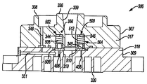
도 8 내지 도 15를 참고하면, 비-선회 스크롤(306)이 압축기(10)에 포함될 수 있다. 비-선회 스크롤(306)은 제1 부재(307) 및 제2 부재(309)를 포함할 수 있다. 제1 부재(307)는 파스너(311)를 이용하여 제2 부재(309)에 부착될 수 있다. 제1 부재(307)는 제1 단부 플레이트 부분(317)을 포함할 수 있으며 제1 부재(307)의 상부 표면에 평행한 동축의 측면 벽(336, 338)에 의해 형성된 환형상 리세스(334)를 포함할 수 있다. 측면 벽(336)은 배출 통로(339)를 형성할 수 있다. 제1 단부 플레이트 부분(317)은 별개의 제1 리세스(342)(도 9 및 도 10)와 제2 리세스(344) 및 제3 리세스(346)(도 11 및 도 12)를 포함할 수 있다. 구멍(348)(도 11 및 도 12에 도시되어 있음)이 제1 단부 플레이트 부분(317)을 관통하여 환형상 리세스(334)로 형성될 수 있다. 8-15, a
제2 부재(309)는 제2 단부 플레이트 부분(318)를 포함할 수 있고, 이 제2 단부 플레이트 부분(318)은 제2 단부 플레이트 부분(318)의 하부 표면에 나선형 베인 또는 랩(320), 제2 단부 플레이트 부분(318)을 관통하여 형성된 배출 통로(319) 및 일련의 반경방향 바깥쪽으로 뻗어 있는 플랜지 부분(321)을 가지고 있다. 나선형 랩(320)은 선회 스크롤(104)과 유사한 선회 스크롤의 랩과 맞물림 결합을 형성하여 일련의 포켓을 만들 수 있다. The
제2 단부 플레이트 부분(318)은 별개의 제1 리세스(343)(도 9 및 도 10) 및 중심 리세스(349)(도 11 및 도 12)를 더 포함할 수 있고, 중심 리세스(349)는 중심 리세스(349)를 통과하는 배출 통로(319)를 가지고 있다. 제1 부재(307)과 제2 부재(309)가 조립되어 비-선회 스크롤(306)를 형성하면, 제1 부재(307)의 리세스(342)는 제2 부재(309)의 리세스(343)와 정렬되어 챔버(347)를 형성할 수 있다. 챔버(347)는 환형상 리세스(334)로부터 격리될 수 있다. 시일 조립체(20)에 대해서 위에서 설명한 것과 대체로 유사한 플로팅 시일 조립체에 대해 가해지는 압력을 제공하기 위해서 구멍(351)(도 11 및 도 12에 도시되어 있음)이 제2 단부 플레이트 부분(318)에 형성되어 제1 부재(307)의 구멍(348)과 연통될 수 있다.The second
제1 통로(350)(도 13에 도시되어 있음)는 비-선회 스크롤(306)의 외측 표면으로부터 리세스(342)로 제1 단부 플레이트 부분(317)을 관통하여 반경방향으로 형성될 수 있다. 한 쌍의 제2 통로(362)는 리세스(343)로부터 비-선회 스크롤(306)의 외측 표면으로 제2 단부 플레이트 부분(318)을 관통하여 반경방향으로 형성될 수 있다. 제2 통로(362)는 흡입 압력 구역과 연통될 수 있다. 제3 통로(366)(도 11 및 도 12)는 배출 압력 구역으로부터 비-선회 스크롤(306)의 외측 표면으로 제1 단부 플레이트 부분(317)을 관통하여 반경방향으로 형성될 수 있다. 예를 들면, 제3 통로(366)는 배출 통로(339)로부터 비-선회 스크롤(306)의 외측 표면으로 형성될 수 있다. 아래에 기술되어 있는 바와 같이, 제1 통로(350) 및 제3 통로(366)는 조절 조립체(227)와 연통될 수 있다. The first passage 350 (shown in FIG. 13) can be formed radially through the first
제2 단부 플레이트 부분(318)는 제1 가변 부피 비율(VVR:Variable Volume Ratio) 포트(406) 및 제2 가변 부피 비율(VVR) 포트(408) 뿐만 아니라 제1 조절 포트(370), 제2 조절 포트(372) 및 제3 조절 포트(374)를 더 포함할 수 있다. 제1 조절 포트(370), 제2 조절 포트(372) 및 제3 조절 포트(374)는 챔버(347)와 연통될 수 있다. 제1 조절 포트(370)는 대체로 조절된 압축기 용량을 한정할 수 있다. The second
제1 조절 포트(370)는 랩(320)의 시작 지점(S')으로부터 반경방향 안쪽으로 적어도 540도에 위치된 압축 포켓들 중의 하나에 위치될 수 있다. 제1 조절 포트(370)는 제2 조절 포트(372) 및 제3 조절 포트(374)에 대하여 반경방향으로 안쪽에 위치될 수 있다. 제1 조절 포트(370)가 랩(320)을 따라서 더 안쪽에 위치되어 있기 때문에, 제1 조절 포트(370), 제2 조절 포트(372) 및 제3 조절 포트(374)가 흡입 압력 구역에 노출될 때 제2 조절 포트(372) 및 제3 조절 포트(374)는 각각 제1 조절 포트(370)로부터 반경방향으로 바깥쪽에 있는 포켓에서의 압축을 제한하는 보조 포트를 형성할 수 있다.The
제1 가변 부피 비율(VVR) 포트(406) 및 제2 가변 부피 비율(VVR) 포트(408)는 제1 조절 포트(370), 제2 조절 포트(372) 및 제3 조절 포트(374)에 대하여 또한 구멍(351)에 대하여 반경방향으로 안쪽에 배치될 수 있다. 제1 가변 부피 비율(VVR) 포트(406) 및 제2 가변 부피 비율(VVR) 포트(408)는 랩(310, 320)(도 16 내지 도 19)에 의해서 형성된 포켓들 중의 하나의 포켓 및 중심 리세스(349)와 연통될 수 있다. 따라서, 제1 가변 부피 비율(VVR) 포트(406) 및 제2 가변 부피 비율(VVR) 포트(408)는 배출 통로(339)와 연통될 수 있다. The first variable volume ratio (VVR)
조절 조립체(227)는 밸브 조립체(376) 및 피스톤 조립체(380)를 포함할 수 있다. 밸브 조립체(376)는 밸브 부재(도시되어 있지 않음)를 내장하고 있는 하우징(382)을 가지고 있는 솔레노이드 밸브를 포함할 수 있다. The
피스톤 조립체(380)는 챔버(347) 내에 배치될 수 있으며 피스톤(398), 시일(400) 및 가압 부재(402)를 포함할 수 있다. 피스톤(398)은 제1 위치와 제2 위치 사이에서 변위될 수 있다. 보다 상세하게는, 밸브 조립체(376)가 리세스(342)를 통기시킬 때 가압 부재(402)가 피스톤(398)을 제1 위치(도 10)로 가압할 수 있다. 밸브 조립체(376)는 리세스(342)를 흡입 압력 구역으로 선택적으로 통기시킬 수 있다. 부가적으로 밸브 조립체(376)는 제1 통로(350) 및 제3 통로(366)와 연통될 수 있다. 밸브 조립체(376)는 제3 통로(366)를 통하여 선택적으로 제1 통로(350)와 배출 압력 구역 사이에 연통이 되게 할 수 있다. 밸브 조립체(376)가 제1 통로(350)와 배출 압력 구역 사이에 연통이 되게 하면, 피스톤(398)은 제1 통로(350)에 의해 제공된 배출 압력에 의해 제2 위치(도 9)로 변위될 수 있다. 피스톤(398)이 제1 위치 및 제2 위치에 있을 때 시일(400)은 제1 통로(350)와 제2 통로(362) 사이의 연통을 차단할 수 있다. The
도 9에 도시되어 있는 바와 같이, 피스톤(398)이 제2 위치에 있을 때, 피스톤(398)는 제1 조절 포트(370), 제2 조절 포트(372) 및 제3 조절 포트(374)를 제2 통로(362)와 연통으로부터 밀봉시킬 수 있다. 피스톤(398)이 도 10에 도시된 제1 위치에 있을 때, 피스톤(398)은 제1 조절 포트(370), 제2 조절 포트(372) 및 제3 조절 포트(374)로부터 변위되어 제1 조절 포트(370), 제2 조절 포트(372) 및 제3 조절 포트(374)와 제2 통로(362) 사이에 연통이 되게 할 수 있다. 따라서, 피스톤(398)이 제1 위치에 있을 때, 제1 조절 포트(370), 제2 조절 포트(372) 및 제3 조절 포트(374)는 각각 흡입 압력 구역과 연통되어 압축기 작동 용량을 감소시킬 수 있다. 부가적으로, 피스톤(398)이 제1 위치에 있을 때, 제1 조절 포트(370), 제2 조절 포트(372) 및 제3 조절 포트(374) 중의 하나 이상은 가스를 낮은 압력에서 작동하는 제1 조절 포트(370), 제2 조절 포트(372) 및 제3 조절 포트(374) 중의 다른 하나로 유동되게 할 수 있다.As shown in FIG. 9, when the
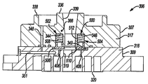
도 11 및 도 12에 도시되어 있는 바와 같이, VVR 조립체(500)는 제1 가변 부피 비율(VVR) 포트(406) 및 제2 가변 부피 비율(VVR) 포트(408)와 배출 통로(339) 사이에 선택적으로 연통이 되게 할 수 있다. VVR 조립체(500)는 제1 피스톤 조립체(502) 및 제2 피스톤 조립체(504)를 포함할 수 있다. 제1 피스톤 조립체(502)는 피스톤(506) 및 스프링과 같은 가압 부재(508)를 포함할 수 있다. 제2 피스톤 조립체(504)는 피스톤(510) 및 스프링과 같은 가압 부재(512)를 포함할 수 있다. 가압 부재(508, 512)는 피스톤(506, 510)을 제1 가변 부피 비율(VVR) 포트(406) 및 제2 가변 부피 비율(VVR) 포트(408)를 밀봉시키기 위해서 피스톤(506, 510)이 제2 단부 플레이트 부분(318)과 맞닿는 제1 위치로 가압할 수 있다. 제1 가변 부피 비율(VVR) 포트(406) 및 제2 가변 부피 비율(VVR) 포트(408)로부터 가해지는 압력이 소정의 레벨을 넘어서면, 제1 가변 부피 비율(VVR) 포트(406) 및 제2 가변 부피 비율(VVR) 포트(408) 내의 가스에 의해 피스톤(506, 510)에 가해지는 힘이 가압 부재(508, 512)에 의해 가해지는 힘보다 커질 수 있고 피스톤(506, 510)은 제1 가변 부피 비율(VVR) 포트(406) 및 제2 가변 부피 비율(VVR) 포트(408)가 배출 통로(339)와 연통되는 제2 위치로 변위될 수 있다. As shown in FIGS. 11 and 12, the
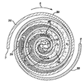
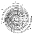
도 16 내지 도 19는 비-선회 스크롤(306)에 대한 선회 스크롤(304)의 다양한 배치상태를 개략적으로 나타내고 있다. 선회 스크롤(304)과 비-선회 스크롤(306)의 맞물림결합은 선회 스크롤(304)과 비-선회 스크롤(306) 사이에 복수의 포켓을 형성한다. 상기 포켓은 "A" 포켓과 "B" 포켓으로 나누어질 수 있다. A 포켓은 선회 스크롤(304)의 반경방향 내측 표면과 비-선회 스크롤(306)의 반경방향 외측 표면 사이에 형성된 포켓이다. B 포켓은 선회 스크롤(304)의 반경방향 외측 표면과 비-선회 스크롤(306)의 반경방향 내측 표면 사이에 형성된 포켓이다. 이러한 A 포켓과 B 포켓은, 작동하는 동안 선회 스크롤(304)과 비-선회 스크롤(306) 사이에 형성된 다양한 A 포켓과 B 포켓을 나타내기 위해서, 서로 다른 음영(shading)으로 표시되어 있다. 도면에 도시된 내용으로부터 알 수 있는 바와 같이, 압축기가 작동하는 동안 3개의 A 포켓과 3개의 B 포켓이 형성된다. 압축기가 작동하는 동안, A 포켓과 B 포켓이 배출 통로(319)쪽으로 반경방향 안쪽으로 이동함에 따라 A 포켓과 B 포켓이 점차적으로 감소하도록 선회 스크롤(304)이 비-선회 스크롤(306)에 대하여 이동한다. 작동하는 동안, 다양한 A 포켓은 제2 조절 포트(372)와 연통될 수 있고 다양한 B 포켓은 제1 조절 포트(370) 및 제3 조절(374)과 연통될 수 있어서 피스톤(398)의 위치에 따라 압축기의 용량을 조절할 수 있다. 제1 조절 포트(370), 제2 조절 포트(372) 및 제3 조절 포트(374)가 통기되면, 대응하는 A 포켓과 B 포켓에서는 압축이 발생하지 않으며, A 포켓과 B 포켓 내에서의 압축은, 피스톤(398)이 제2 위치에 있을 때 또는 A 포켓이 제2 조절 포트(372)의 반경방향 안쪽에 있고 제2 조절 포트(372)로부터 격리되어 있으며 B 포켓이 반경방향으로 가장 안쪽에 있는 제1 조절 포트(370)의 반경방향 안쪽에 있고 제1 조절 포트(370)로부터 격리되어 있을 때와 같이, A 포켓과 B 포켓이 통기되지 않은 배치위치에 있을 때에만 발생한다. 16-19 schematically illustrate various arrangements of the swinging
도 16 내지 도 19에 도시되어 있는 바와 같이, 선회 스크롤(304) 또는 비-선회 스크롤(306)이 대칭일 때의 압축 싸이클의 일부분이 제1 조절 포트(370), 제2 조절 포트(372) 및 제3 조절 포트(374)와 제1 가변 부피 비율(VVR) 포트(406) 및 제2 가변 부피 비율(VVR) 포트(408)의 작동을 나타내기 위해 도시되어 있다. 대칭적인 선회 스크롤(304) 및 비-선회 스크롤(306)은 각각 대체로 180도 떨어져 있는 각 랩(310, 320)의 시작 지점(T', S')을 가질 수 있다. 대칭적인 스크롤은 A 포켓과 B 포켓을 대체로 180도 떨어져 있는 상태로 동시에 형성한다. 비-조절 압축 동안, 반대쪽에 있는 A 포켓과 B 포켓이 동일한 압축을 받아서 선회 스크롤(304)과 비-선회 스크롤(306) 내에 대칭적인 압력 분배를 초래한다. As shown in FIGS. 16-19, a portion of the compression cycle when the swinging
도 16에는, 제1 용량 조절 포켓(600, 602)이 나타나 있는 제1 위치에서의 선회 스크롤(304)이 도시되어 있다. 대체로 제1 용량 조절 포켓(600, 602)은, 제1 조절 포트(370)에 대하여 반경방향 안쪽에 배치되어 있으며 제1 용량 조절 포켓(600, 602)이 형성되는 시점으로부터 제1 용량 조절 포켓(600, 602)의 부피가 배출 통로(319)를 통하여 소실될 때까지 제1 조절 포트(370)로부터 격리되어 있는 반경방향으로 가장 바깥쪽 압축 포켓으로 형성될 수 있다. 따라서, 제1 용량 조절 포켓(600, 602)의 부피는 제1 용량 조절 포켓(600, 602)과 관련된 압축 싸이클의 나머지 부분 동안 제1 조절 포트(370)로부터 분리될 수 있다. 제1 용량 조절 포켓(600, 602)의 부피는 선회 스크롤(304)이 제1 위치에 있을 때 최대 부피로 될 수 있고 배출 통로(319)를 통하여 제1 용량 조절 포켓(600, 602)의 부피가 소실될 때까지 연속적으로 압축될 수 있다.In FIG. 16, the pivoting
선회 스크롤(304)이 제1 위치에 있을 때 선회 스크롤(304)의 나선형 랩(310)은 제1 배치위치에서 나선형 랩(320)의 외측 반경방향 표면과 맞닿을 수 있고 제1 배치위치와 대체로 반대인 제2 배치위치에서 나선형 랩(320)의 내측 반경방향 표면과 맞닿을 수 있다. 선회 스크롤(304)이 제1 위치에 있을 때 제1 조절 포트(370)는 나선형 랩(310)에 의해 밀봉될 수 있다. When the
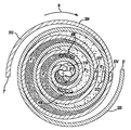
도 17에는, 제2 용량 조절 포켓(604, 606)이 나타나 있는 제2 위치에서의 선회 스크롤(304)이 도시되어 있다. 제2 위치에서, 대체로 제2 용량 조절 포켓(604, 606)은, 제1 조절 포트(370)에 대하여 반경방향 안쪽에 배치되어 있으며 선회 스크롤(304)이 제2 위치에 있는 시점으로부터 제2 용량 조절 포켓(604, 606)의 부피가 배출 통로(319)를 통하여 소실될 때까지 제1 조절 포트(370)로부터 격리되어 있는 반경방향으로 가장 바깥쪽 압축 포켓으로 형성될 수 있다. 선회 스크롤(304)이 제1 위치로부터 제2 위치로 이동하는 것에 의해 초래되는 압축 후에 제2 용량 조절 포켓(604, 606)은 제1 용량 조절 포켓(600, 602)에 대응할 수 있다. 예를 들면, 제1 위치로부터 제2 위치까지의 압축은 구동 샤프트의 약 20도의 회전에 대응할 수 있다. In FIG. 17, a
선회 스크롤(304)이 제2 위치에 있을 때 선회 스크롤(304)의 나선형 랩(310)은 제3 배치위치에서 나선형 랩(320)의 외측 반경방향 표면과 맞닿을 수 있고 제3 배치위치와 대체로 반대인 제4 배치위치에서 나선형 랩(320)의 내측 반경방향 표면과 맞닿을 수 있다. 선회 스크롤(304)이 제2 위치에 있을 때 제1 조절 포트(370)는 제4 배치위치에 대응하는 제2 각도 위치에서 시작하여 구동 샤프트의 회전 방향(R)과 대체로 반대로 나선형 랩(310)을 따라 적어도 20도 정도 뻗을 수 있다. 선회 스크롤(304)이 제2 위치에 있을 때 제1 조절 포트(370)는 나선형 랩(310)에 의해 밀봉될 수 있다. When the
도 16 및 도 17에 도시되어 있는 바와 같이, 포켓 A3와 같은, 제1 용량 조절 포켓(600, 602) 및 제2 용량 조절 포켓(604, 606)으로부터 반경방향 바깥쪽에 배치된 몇 개의 포켓은 제1 조절 포트(370), 제2 조절 포트(372) 및 제3 조절 포트(374) 중의 적어도 하나와 연통될 수 있는 반면에, 포켓 B3와 같은 다른 포켓은 상기 포트들과 연통되지 않는다.As shown in FIGS. 16 and 17, several pockets disposed radially outward from the first dose adjustment pockets 600, 602 and the second dose adjustment pockets 604, 606, such as pocket A 3 , While it may be in communication with at least one of the
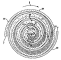
도 18과 도 19를 참고하면, 제1 가변 부피 비율(VVR) 포트(406) 및 제2 가변 부피 비율(VVR) 포트(408)에 대한 VVR 작동이 도시되어 있다. 도 18에는, 제1 VVR 포켓(608, 610)이 나타나 있는 제3 위치에서의 선회 스크롤(304)이 도시되어 있다. 대체로 제1 VVR 포켓(608, 610)은, 제1 가변 부피 비율(VVR) 포트(406)에 대하여 반경방향 바깥쪽에 배치되어 있으며 압축 싸이클이 개시되는 시점으로부터 제1 VVR 포켓(608, 610)이 형성될 때까지 제1 가변 부피 비율(VVR) 포트(406)로부터 격리되어 있는 반경방향으로 가장 안쪽 압축 포켓으로 형성될 수 있다. 따라서, 제1 VVR 포켓(608, 610)은 압축 싸이클의 나머지 기간 동안 제1 가변 부피 비율(VVR) 포트(406)와 연통될 수 있다. 제1 VVR 포켓(608, 610)의 부피는, 선회 스크롤(304)이 제3 위치에 있을 때 최대 부피로 될 수 있으며 제1 VVR 포켓(608, 610)의 부피가 배출 통로(319)를 통하여 소실될 때까지 연속적으로 압축될 수 있다. Referring to FIGS. 18 and 19, VVR operation is shown for a first variable volume ratio (VVR)
선회 스크롤(304)이 제3 위치에 있을 때 선회 스크롤(304)의 나선형 랩(310)은 제5 배치위치에서 나선형 랩(320)의 외측 반경방향 표면과 맞닿을 수 있고 제5 배치위치와 대체로 반대인 제6 배치위치에서 나선형 랩(320)의 내측 반경방향 표면과 맞닿을 수 있다. 선회 스크롤(304)이 제3 위치에 있을 때 제1 가변 부피 비율(VVR) 포트(406)는 제5 배치위치에 대응하는 각도 위치에서 시작하여 구동 샤프트의 회전 방향(R)으로 나선형 랩(310)을 따라 적어도 20도 정도 뻗을 수 있다.When the
도 19에는, 제2 VVR 포켓(612, 614)이 나타나 있는 제4 위치에서의 선회 스크롤(304)이 도시되어 있다. 제4 위치에서, 대체로 제2 VVR 포켓(612, 614)은, 제2 가변 부피 비율(VVR) 포트(408)에 대하여 반경방향 바깥쪽에 배치되어 있으며 압축 싸이클이 개시되는 시점으로부터 제2 VVR 포켓(612, 614)이 형성될 때까지 제2 가변 부피 비율(VVR) 포트(408)로부터 격리되어 있는 반경방향으로 가장 안쪽 압축 포켓으로 형성될 수 있다. 선회 스크롤(304)이 제3 위치로부터 제4 위치까지 이동하는 것에 의해 초래되는 압축 후에 제2 VVR 포켓(612, 614)은 제1 VVR 포켓(608, 610)에 대응할 수 있다. 예를 들면, 제3 위치로부터 제4 위치까지의 압축은 구동 샤프트의 약 40도의 회전에 대응할 수 있다. 선회 스크롤(304)이 제4 위치에 있을 때 제1 가변 부피 비율(VVR) 포트(406)의 일부분은 제2 VVR 포켓(612, 614)과 연통될 수 있다. 19, a
선회 스크롤(304)이 제4 위치에 있을 때 선회 스크롤(304)의 나선형 랩(310)은 제7 배치위치에서 나선형 랩(320)의 외측 반경방향 표면과 맞닿을 수 있고 제7 배치위치와 대체로 반대로 제8 배치위치에서 나선형 랩(320)의 내측 반경방향 표면과 맞닿을 수 있다. 선회 스크롤(304)이 제4 위치에 있을 때 제2 가변 부피 비율(VVR) 포트(408)는 제8 배치위치에 대응하는 제4 각도 위치에서 시작하여 구동 샤프트의 회전 방향(R)과 대체로 반대로 나선형 랩(310)을 따라 적어도 20도 정도 뻗을 수 있다.When the
압축 프로세스 동안, A 포켓과 B 포켓은 점진적으로 반경방향 안쪽으로 이동하며 배출 통로(319)를 통하여 소실된다. 용량 조절이 되지 않을 때에는, 모든 A 포켓과 B 포켓이 압축된다. 그러나, 용량 조절이 이루어지는 동안에는, 몇 개의 포켓은 통기되고 다른 포켓은 통기되지 않는다. 예를 들면, 도 16 및 도 17에 도시되어 있는 바와 같이, 선회 스크롤(304)이 제1 위치와 제2 위치에 있을 때, 포켓 A3는 제2 조절 포트(372)를 통하여 통기되는 반면에 포켓 A2, 포켓 B2, 그리고 포켓 B3 는 모두 압축되고 포켓 A1과 B1은 배출 통로(319)를 통하여 소실된다. 선회 스크롤(304)이 제3 위치로 이동함에 따라, 도 18에 도시되어 있는 바와 같이, 포켓 A1과 포켓 B1은 배출 통로(319)를 통하여 소실되고 새로운 포켓 A4과 포켓 B4가 형성된다. 제3 위치에서는, 포켓 B4와 포켓 B3가 제3 조절 포트(374)와 제1 조절 포트(370)를 통하여 통기되는 반면에 포켓 B2는 압축되거나, 배출 통로(319)를 통하여 소실되거나, 압축되면서 배출 통로(319)를 통하여 소실된다. 마찬가지로, 포켓 A4는 제2 조절 포트(372)를 통하여 통기되는 반면에 포켓 A3는 압축되고 포켓 A2는 압축되거나, 배출 통로(319)를 통하여 소실되거나, 압축되면서 배출 통로(319)를 통하여 소실된다. 선회 스크롤(304)이 제4 위치로 이동함에 따라, 도 19에 도시되어 있는 바와 같이, 포켓 B3와 포켓 B4는 제3 조절 포트(374)와 제1 조절 포트(370)를 통하여 계속하여 통기되는 반면에 포켓 A4는 제2 조절 포트(372)를 통하여 계속하여 통기된다. 선회 스크롤(340)이 자신의 궤도를 따라서 계속 이동함에 따라, 기존의 A 포켓과 B 포켓이 배출 통로(319)를 통하여 소실되면서 다수의 새로운 A 포켓과 B 포켓이 형성된다.During the compression process, the A and B pockets gradually move radially inward and are lost through the
제3 조절 포트(374), 제2 조절 포트(372) 및 제1 조절 포트(370)의 배치구조로 인해, 반경방향으로 반대쪽에 있는 A 포켓과 B 포켓 사이에서 압력 차이가 발생한다. 예를 들면, 도 17에 도시되어 있는 바와 같이, 포켓 B2는 제1 조절 포트(370)를 통한 통기 상태가 막 종료되는 반면에 포켓 A2는 궤도상으로 보다 빨리 통기 상태가 종료되고 구동 샤프트의 회전에 있어서 보다 빠른 지점에서 제2 조절 포트(372)와 연통된 상태로 있는 것으로 인해서 보다 많은 압축을 받기 때문에 포켓 A2의 압력이 포켓 B2의 압력보다 더 크게 된다. 이러한 압력 차이의 결과로서, 부가적인 부하(loading)가 올덤 커플링에 작용하여 선회 스크롤(304)을 자신의 선회 방향(도 16 내지 도 19에 도시된 도면에서 시계방향)으로 선회하도록 한다. 올덤 커플링에 작용하는 부가적인 부하는 올덤 커플링과 선회 스크롤(304) 사이의 일정한 접촉상태가 유지될 가능성을 높이기 때문에 압축기가 작동하는 동안 소음을 감소시키는데 도움을 준다. 결과적으로, 조절이 이루어지는 동안 압축 메카니즘의 A 포켓과 B 포켓 사이에서 비대칭적인 또는 불균형적인 압력 패턴이 전개된다. Due to the arrangement of the third regulating
따라서, 반경방향으로 이격되어 있으며 용량 조절이 이루어질 때 올덤 커플링에 부가적인 부하를 제공하여 올덤 커플링과 선회 스크롤(304) 사이의 접촉상태를 유리하게 유지시킬 수 있는 불균형적인 압력 분배상태를 만드는 단일 세트의 인접한 제1 조절 포트(370), 제2 조절 포트(372) 및 제3 조절 포트(374)를 제공하기 위해서 단일 조절 조립체가 비-선회 스크롤(306)에 유리하게 위치될 수 있다. 올덤 커플링과 선회 스크롤(304) 사이의 연속적인 접촉에 의해 압축기가 작동하는 동안 올덤 커플링이 선회 스크롤(304)과 결합되고 선회 스크롤(304)로부터 분리되는 것으로 인해서 발생될 수 있는 소음을 상당히 감소시킬 수 있다.Thus, they are radially spaced and provide an additional load on the Oldham coupling when capacity adjustments are made, creating an unbalanced pressure distribution that can advantageously maintain contact between the Oldham coupling and the swinging
도 22 내지 도 25를 참고하면, 조절 조립체와 포트(370', 372', 374')의 배치위치에 대한 다른 구성이 도시되어 있다. 이러한 구성에서, 피스톤 조립체(380)는 도 8 내지 도 19에 도시된 배치상태로부터 180도 회전한 배치상태에 배치되어 있다. 결과적으로, 포트(370', 372', 374')의 배치위치도 위에서 설명한 것으로부터 180도 회전되어 있으며 A' 포켓은 포트(370')와 포트(374')을 통하여 통기될 수 있고 B' 포켓은 포트(372')를 통하여 통기될 수 있다.Referring to Figures 22-25, another configuration for the placement of the adjustment assembly and the ports 370 ', 372', 374 'is shown. In this configuration, the
압축 프로세스 동안, A' 포켓과 B' 포켓은 점진적으로 반경방향 안쪽으로 이동하며 배출 통로(319)를 통하여 소실된다. 용량 조절이 되지 않을 때에는, 모든 A' 포켓과 B' 포켓이 압축된다. 그러나, 용량 조절이 이루어지는 동안에는, 몇 개의 포켓은 통기되고 다른 포켓은 통기되지 않는다. 예를 들면, 도 22 및 도 23에 도시되어 있는 바와 같이, 선회 스크롤(304)이 제1 위치와 제2 위치에 있을 때, 포켓 B'3는 포트(372')를 통하여 통기되는 반면에 포켓 A'1, 포켓 A'2, 그리고 포켓 B'2 는 압축되고 포켓 A'1과 B'1은 압축되거나, 배출 통로(319)를 통하여 소실되거나, 압축되면서 배출 통로(319)를 통하여 소실된다. 선회 스크롤(304)이 제3 위치로 이동함에 따라, 도 24에 도시되어 있는 바와 같이, 포켓 A'1과 포켓 B'1은 배출 통로(319)를 통하여 소실되고 새로운 포켓 A'4과 포켓 B'4가 형성된다. 제3 위치에서는, 포켓 A'4와 포켓 A'3가 포트(374')와 포트(370')를 통하여 통기되는 반면에 포켓 A'2는 압축되거나, 배출 통로(319)를 통하여 소실되거나, 압축되면서 배출 통로(319)를 통하여 소실된다. 마찬가지로, 포켓 B'4는 포트(372')를 통하여 통기되는 반면에 포켓 B'3는 압축되고 포켓 B'2는 압축되거나, 배출 통로(319)를 통하여 소실되거나, 압축되면서 배출 통로(319)를 통하여 소실된다. 선회 스크롤(304)이 제4 위치로 이동함에 따라, 도 25에 도시되어 있는 바와 같이, 포켓 A'3와 포켓 A'는 포트(374')와 포트(370')를 통하여 계속하여 통기되는 반면에 포켓 B'4는 포트(372')를 통하여 계속하여 통기된다. 선회 스크롤(340)이 자신의 궤도를 따라서 계속 이동함에 따라, 기존의 A' 포켓과 B' 포켓이 배출 통로(319)를 통하여 소실되면서 다수의 새로운 A' 포켓과 B' 포켓이 형성된다.During the compression process, the A 'and B' pockets gradually move radially inward and are lost through the
포트(374'), 포트(372') 및 포트(370')의 배치구조로 인해, 반경방향으로 반대쪽에 있는 A' 포켓과 B' 포켓 사이에서 압력 차이가 발생한다. 예를 들면, 도 23에 도시되어 있는 바와 같이, 포켓 A'2는 포트(370')를 통한 통기 상태가 막 종료되는 반면에 포켓 B'2는 궤도상으로 보다 빨리 통기 상태가 종료되고 구동 샤프트의 회전에 있어서 보다 빠른 지점에서 포트(372')와 연통된 상태로 있는 것으로 인해서 보다 많은 압축을 받기 때문에 포켓 B'2의 압력이 포켓 A'2의 압력보다 더 크게 된다. 이러한 압력 차이의 결과로서, 감소된 부하가 올덤 커플링에 작용하여 선회 스크롤(304)을 자신의 선회 방향의 반대 방향(도 22 내지 도 25에 도시된 도면에서 반시계방향)으로 선회하도록 한다. 결과적으로, 조절이 이루어지는 동안 압축 메카니즘의 A' 포켓과 B' 포켓 사이에서 불균형적인 압력 패턴이 전개된다.Due to the arrangement of the ports 374 ', 372' and 370 ', a pressure difference occurs between the A' and B 'pockets that are opposite in the radial direction. For example, as shown in FIG. 23, pocket A ' 2 has just finished the venting through port 370' while pocket B ' 2 has exited the vent sooner on track and the drive shaft The pressure in pocket B ' 2 is greater than the pressure in pocket A' 2 because of the more compression due to being in communication with port 372 'at a faster point in the rotation of. As a result of this pressure difference, a reduced load acts on the Oldham coupling to cause the
도 26 내지 도 33을 참고하면, 선회 스크롤(904)과 비-선회 스크롤(906)이 비대칭적인 스크롤인 경우의 압축 싸이클의 일부분이 도시되어 구동 샤프트가 345도 회전하는 동안 단일 조절 조립체 및 단일 세트의 조절 포트(970, 972, 974)의 작동을 나타내고 있다. 선회 스크롤(904) 및 비-선회 스크롤(906)는 압축기(10)에 포함될 수 있으며 단일 조절 조립체 및 단일 세트의 조절 포트(970, 972, 974)를 이용한다. 선회 스크롤(904) 및 비-선회 스크롤(906)은 선회 스크롤(104, 304) 및 비-선회 스크롤(106, 306)과 대체로 유사하다. 따라서, 선회 스크롤(904) 및 비-선회 스크롤(906), 단일 조절 조립체, 그리고 단일 세트의 조절 포트(970, 972, 974)는 아래에 기술한 예외사항을 제외하고는 상기 설명이 동일하게 적용된다고 이해하여 상세하게 설명하지 않는다. With reference to FIGS. 26-33, a portion of the compression cycle when the
비대칭적인 선회 스크롤(904) 및 비-선회 스크롤(906)은 각각 대체로 서로 정렬될 수 있는 각각의 랩(910, 920)의 시작 지점(T", S")을 가지고 있다. 비대칭적인 스크롤은 구동 샤프트가 180도 회전할 때마다 A 포켓 및 B 포켓이 순차적으로 형성되게 한다. 결과적으로, 제1 A 포켓(도 30에서 A3)이 형성되기 전에 제1 B 포켓(도 26에서 B3)이 형성되어 구동 샤프트의 180도 회전에 의해 압축을 받는다. B 포켓과 A 포켓의 순차적인 형성에 의해, 비-조절식 압축기가 작동하는 동안 B 포켓의 복합 압력(combined pressure)이 A 포켓의 복합 압력보다 더 큰 상태로 선회 스크롤(904)과 비-선회 스크롤(906) 사이에 불균형적인 압력 분배가 유발된다. 이 불균형적인 압력 분배는 올덤 커플링에 작용하는 부하를 감소시켜서 선회 스크롤(904)이 자신의 선회 방향과 반대 방향(도 26 내재 도 33에 도시된 도면에서 반시계방향)으로 선회하도록 한다. The
압축 프로세스 동안, 구동 샤프트가 회전함에 따라 A 포켓과 B 포켓은 점진적으로 반경방향 안쪽으로 이동하고 배출 통로(919)를 통하여 소실된다. 도 26 내지 도 33은 구동 샤프트의 각도 위치가 0도, 45도, 105도, 165도, 180도, 225도, 285도, 그리고 345도인 경우에 각각 대응한다. 용량 조절이 되지 않을 때에는, 모든 A 포켓과 B 포켓이 압축된다. 그러나, 용량 조절이 이루어지는 동안에는, B 포켓 중의 몇개는 포트(974, 970)를 통하여 통기될 수 있고 A 포켓 중의 몇개는 포트(972)를 통하여 통기될 수 있는 반면에 다른 포켓들은 통기되지 않는다. 예를 들면, 도 26 및 도 27에 도시되어 있는 바와 같이, 구동 샤프트가 0도의 각도 위치와 45도의 각도 위치에 있을 때, 포켓 B3, 포켓 A2 및 포켓 B2는 각각 포트 974, 포트 972 및 포트 970을 통하여 통기되는 반면에, 포켓 A1 및 포켓 B1은 압축된다. 선회 스크롤(904)이 구동 샤프트의 회전에 의해 계속하여 이동함에 따라, 도 28에 도시되어 있는 바와 같이, 포트 972가 선회 스크롤(904)에 의해 덮혀져서 포켓 A2는 통기를 멈추고 압축을 시작하는 반면에 포켓 B3와 포켓 B2는 포트 974와 포트 972를 통하여 계속하여 통기된다. During the compression process, as the drive shaft rotates, the A and B pockets gradually move radially inward and are lost through the
선회 스크롤(904)이 구동 샤프트의 회전에 의해 계속하여 이동함에 따라, 도 29 내지 도 31에 도시되어 있는 바와 같이, 새로운 포켓 B3가 형성되고 포켓 B3, 포켓 A3 및 포켓 B2는 각각 포트 974, 포트 972 및 포트 970를 통하여 통기되는 반면에, 포켓 A2는 계속하여 압축되고 배출 통로(919)로 접근하며 포켓 A1 및 포켓 B1은 압축되거나, 배출 통로(919)를 통하여 소실되거나, 압축되면서 배출 통로(919)를 통하여 소실된다. 선회 스크롤(904)이 구동 샤프트의 회전에 의해 계속하여 이동함에 따라, 도 32에 도시되어 있는 바와 같이, 포트 974 및 포트 970가 선회 스크롤(904)에 의해 덮혀져서 포켓 A3는 포트 972를 통하여 계속하여 통기되는 반면에, 포켓 A1, 포켓 A2, 포켓 A3 및 포켓 B3는 압축되고 배출 통로(919)로 접근하며 포켓 A1 및 포켓 B1은 압축되거나, 배출 통로(919)를 통하여 소실되거나, 압축되면서 배출 통로(919)를 통하여 소실된다.As the
선회 스크롤(904)이 구동 샤프트의 회전에 의해 계속하여 이동함에 따라, 도 33에 도시되어 있는 바와 같이, 포켓 A1과 포켓 B1은 배출 통로(919)를 통하여 소실되고, 새로운 포켓 B4가 형성되며, 포켓 B3가 포트 970을 통하여 통기되기 시작하는 반면에, 포켓 B4 및 포켓 A3는 포트 974 및 포트 972를 통하여 통기되고 포켓 A2와 포켓 B2는 계속하여 압축되고 배출 통로(919)로 접근한다. 선회 스크롤(904)은 구동 샤프트의 회전에 의해 계속하여 이동하여 도 26에 도시된 시작 위치로 되돌아오고, 상기 프로세스는 다시 시작된다. As the
포트 974, 포트 972 및 포트 970의 배치구조로 인해, 압축기의 조절 작동이 이루어지는 동안 포트 970의 반경방향 안쪽에 배치되어 있으며 포트 970으로부터 격리되는 있는 B 포켓과 포트 972의 반경방향 안쪽에 배치되어 있으며 포트 972로부터 격리되어 있는 반경방향으로 반대쪽의 A 포켓 사이에서 압력 차이가 발생한다. 예를 들면, 도 26에 도시되어 있는 바와 같이, 포켓 B1는 포트 970을 통한 통기 상태가 막 종료되는 반면에 포켓 A1는 궤도상으로 보다 빨리 통기 상태가 종료되고 구동 샤프트의 회전에 있어서 보다 빠른 지점에서 포트 972와 연통된 상태로 있는 것으로 인해서 보다 많은 압축을 받기 때문에 포켓 A1의 압력이 포켓 B1의 압력보다 더 크게 된다. 이러한 압력 차이의 결과로서, 부가적인 부하가 올덤 커플링에 작용하여 선회 스크롤(904)을 자신의 선회 방향(도 26 내지 도 33에 도시된 도면에서 시계방향)으로 선회하도록 한다. 올덤 커플링에 작용하는 부가적인 부하는 올덤 커플링과 선회 스크롤(904) 사이의 일정한 접촉상태가 유지될 가능성을 높이기 때문에 압축기가 작동하는 동안 소음을 감소시키는데 도움을 준다. 결과적으로, 조절이 이루어지는 동안 압축 메카니즘의 A 포켓과 B 포켓 사이에서 불균형적인 압력 패턴이 전개된다. Due to the arrangement of
따라서, 반경방향으로 이격되어 있으며 용량 조절이 이루어질 때 올덤 커플링에 부가적인 부하를 제공하여 올덤 커플링과 선회 스크롤(904) 사이의 접촉상태를 유리하게 유지시킬 수 있는 불균형적인 압력 분배상태를 만드는 단일 세트의 인접한 포트 970, 포트 972 및 포트 974를 제공하기 위해서 단일 조절 조립체가 비-선회 스크롤(906)에 유리하게 위치될 수 있다. 올덤 커플링과 선회 스크롤(904) 사이의 연속적인 접촉에 의해 압축기가 작동하는 동안 올덤 커플링이 선회 스크롤(904)과 결합되고 선회 스크롤(904)로부터 분리되는 것으로 인해서 발생될 수 있는 소음을 상당히 감소시킬 수 있다.Thus, they are radially spaced and provide an additional load on the Oldham coupling when capacity adjustments are made, creating an unbalanced pressure distribution that can advantageously maintain contact between the Oldham coupling and the swinging
도 20 및 도 21과 관련하여 위에서 설명한 유체 주입이 동일한 방식으로 선회 스크롤(304, 904)과 함께 이용될 수 있다. 따라서, 포트(370, 370', 970, 372, 372', 972, 374, 374', 974)를 통하여 유체 주입이 실현될 수 있다. The fluid injection described above with respect to FIGS. 20 and 21 can be used with the pivoting scrolls 304, 904 in the same manner. Thus, fluid injection can be realized through the
상기한 가변 부피 비율(VVR:Variable Volume Ratio)이 위에서 설명한 것과 유사한 방식으로 비-선회 스크롤(904)과 함께 이용될 수도 있다. The Variable Volume Ratio (VVR) described above may be used with the
게다가, 비-선회 스크롤(304, 904) 및 A 포켓과 B 포켓의 불균형적인 부하와 관련하여 설명한 조절이 단 2개의 포트(170, 174)를 가지고 있는 비-선회 스크롤(104)에서 실현될 수 있다. 조절은 3개보다 많은 포트를 가진 경우에도 실현될 수 있다. 부가적으로, 해당 포켓이 가장 안쪽 포트의 반경방향 안쪽으로 이동하여 가장 안쪽 포트로부터 격리된 이후까지 압축이 일어나지 않도록 2개의 상이한 포트(예를 들면, 포트(370, 374) 또는 포트(370', 374'), 또는 포트(970, 974))와 연통되며 상기 포트의 양쪽 모두와 동시에 연속적으로 연통되는 A 포켓과 B 포켓을 가지고 있는 것이 유리할 수 있다. 포트 372 또는 포트 372' 또는 포트 972와 같은, 하나의 포트와만 연통되는 다른 A 포켓과 B 포켓이 형성된 직후의 포트와 연통된다면 더욱 유리할 수 있다. 2개의 포트와의 연속적인 연통 및 형성되기 전의 포트와의 연통은 해당 포켓이 반경방향으로 가장 안쪽 포트를 지나서 이 반경방향으로 가장 안쪽 포트로부터 격리되기 전에 압축을 유리하게 제한할 수 있다. In addition, the adjustments described with respect to the
본 발명을 다양한 실시예 및 다양한 구성과 관련하여 설명하였지만, 원하는 작동을 달성하기 위하여 상기 실시예와 구성의 다양한 특징은 서로 결합되고 조화될 수 있다. 상기 설명은 단지 예시적인 것이며 본 발명 및 청구항의 범위를 제한하는 것은 아니다.While the invention has been described in connection with various embodiments and various configurations, various features of the embodiments and configurations can be combined and harmonized with each other to achieve the desired operation. The foregoing description is exemplary only and does not limit the scope of the invention and the claims.
Claims (48)
선회 스크롤 및 비-선회 스크롤을 가지고 있는 압축 메카니즘;
상기 비-선회 스크롤에서 서로 인접하게 배치되어 있는 제1 포트 및 제2 포트; 그리고
상기 제1 포트 및 제2 포트와 유체 공급원 사이의 유체 연통을 제한하는 제1 위치와 상기 제1 포트 및 제2 포트와 상기 유체 공급원 사이의 유체 연통을 허용하는 제2 위치 사이에서 이동가능한 차단 장치;
를 포함하고 있고,
상기 선회 스크롤과 비-선회 스크롤은 서로 맞물려서 선회 스크롤과 비-선회 스크롤 사이에 이동하는 제1 유체 포켓 및 제2 유체 포켓을 형성하고, 상기 제1 유체 포켓 및 제2 유체 포켓은 서로 각도상으로 이격되어 있으며 제1 유체 포켓 및 제2 유체 포켓이 반경방향으로 가장 안쪽 위치를 향해서 반경방향 안쪽으로 이동함에 따라 크기가 감소되고,
상기 제1 포트 및 제2 포트는, 상기 제1 포트가 제1 반경방향 위치에서 상기 제1 유체 포켓과 연통하고 상기 제2 포트가 제2 반경방향 위치에서 상기 제2 유체 포켓과 연통하도록 서로 반경방향으로 이격되어 있고, 상기 제2 반경방향 위치는 상기 제1 반경방향 위치와 상기 반경방향으로 가장 안쪽 위치에 대해 반경방향으로 중간에 위치하고 있고,
상기 제1 유체 포켓 및 제2 유체 포켓은 각각 제1 유체 압력 및 제2 유체 압력을 가지고 있고, 상기 제1 유체 포켓과 제2 유체 포켓 중의 적어도 하나가 상기 제1 포트와 제2 포트 중의 적어도 하나를 통하여 상기 유체 공급원과 연통된 후에 상기 제1 유체 압력과 제2 유체 압력 중의 하나는 상기 제1 유체 압력과 제2 유체 압력 중의 다른 하나에 비하여 불균형적인 압력 변화를 가지고, 상기 불균형적인 압력 변화는 상기 선회 스크롤을 상기 비-선회 스크롤에 대하여 가압하는 것을 특징으로 하는 압축기.As a compressor,
A compression mechanism with pivoting scrolls and non-orbiting scrolls;
First and second ports disposed adjacent to each other in the non-orbiting scroll; And
A shutoff device movable between a first position restricting fluid communication between the first port and the second port and a fluid source and a second position allowing fluid communication between the first port and the second port and the fluid source ;
And,
The pivoting scroll and the non-orbiting scroll mesh with each other to form a first fluid pocket and a second fluid pocket that move between the pivoting scroll and the non-orbiting scroll, the first fluid pocket and the second fluid pocket being angular to each other. Spaced and reduced in size as the first fluid pocket and the second fluid pocket move radially inward toward the innermost position in the radial direction,
The first port and the second port are radiused from each other such that the first port is in communication with the first fluid pocket in a first radial position and the second port is in communication with the second fluid pocket in a second radial position. Spaced apart in a direction, and the second radial position is radially intermediate with respect to the first radial position and the radially innermost position,
The first fluid pocket and the second fluid pocket have a first fluid pressure and a second fluid pressure, respectively, and at least one of the first fluid pocket and the second fluid pocket is at least one of the first port and the second port. After communicating with the fluid source through one of the first and second fluid pressures has an unbalanced pressure change compared to the other of the first and second fluid pressures, the unbalanced pressure change is And pressurize the pivoting scroll against the non-orbiting scroll.
셸 내에 배치되어 있으며 선회 스크롤 및 비-선회 스크롤을 가지고 있는 압축 메카니즘;
상기 비-선회 스크롤에서 서로 인접하게 배치되어 있는 제1 포트 및 제2 포트; 그리고
상기 제1 포트 및 제2 포트와 유체 공급원 사이의 유체 연통을 제한하는 제1 위치와 상기 제1 포트 및 제2 포트와 상기 유체 공급원 사이의 유체 연통을 허용하는 제2 위치 사이에서 이동가능한 차단 장치;
를 포함하고 있고,
상기 선회 스크롤과 비-선회 스크롤은 서로 맞물려서 선회 스크롤과 비-선회 스크롤 사이에 이동하는 제1 유체 포켓 및 제2 유체 포켓을 형성하고, 상기 제1 유체 포켓 및 제2 유체 포켓은 서로 각도상으로 이격되어 있으며 제1 유체 포켓 및 제2 유체 포켓이 반경방향으로 가장 안쪽 위치를 향해서 반경방향 안쪽으로 이동함에 따라 크기가 감소되고,
상기 제1 포트 및 제2 포트는, 상기 제1 포트가 제1 반경방향 위치에서 상기 제1 유체 포켓과 연통하고 상기 제2 포트가 제2 반경방향 위치에서 상기 제2 유체 포켓과 연통하도록 서로 반경방향으로 이격되어 있고, 상기 제2 반경방향 위치는 상기 제1 반경방향 위치와 상기 반경방향으로 가장 안쪽 위치에 대해 반경방향으로 중간에 위치하고 있고,
상기 제1 유체 포켓 및 제2 유체 포켓은, 상기 제1 유체 포켓과 제2 유체 포켓 중의 적어도 하나가 상기 제1 포트와 제2 포트 중의 적어도 하나를 통하여 흡입 압력 구역과 연통된 후에 불균형적으로 변화하는 제1 유체 압력 및 제2 유체 압력을 각각 가지고 있고, 상기 제1 유체 포켓 및 제2 유체 포켓의 유체 압력에 있어서의 불균형적인 변화는 상기 선회 스크롤을 상기 비-선회 스크롤에 대하여 가압하는 것을 특징으로 하는 압축기.As a compressor,
A compression mechanism disposed within the shell and having pivoting scrolls and non-orbiting scrolls;
First and second ports disposed adjacent to each other in the non-orbiting scroll; And
A shutoff device movable between a first position restricting fluid communication between the first port and the second port and a fluid source and a second position allowing fluid communication between the first port and the second port and the fluid source ;
And,
The pivoting scroll and the non-orbiting scroll mesh with each other to form a first fluid pocket and a second fluid pocket that move between the pivoting scroll and the non-orbiting scroll, the first fluid pocket and the second fluid pocket being angular to each other. Spaced and reduced in size as the first fluid pocket and the second fluid pocket move radially inward toward the innermost position in the radial direction,
The first port and the second port are radiused from each other such that the first port is in communication with the first fluid pocket in a first radial position and the second port is in communication with the second fluid pocket in a second radial position. Spaced apart in a direction, and the second radial position is radially intermediate with respect to the first radial position and the radially innermost position,
The first fluid pocket and the second fluid pocket vary disproportionately after at least one of the first fluid pocket and the second fluid pocket is in communication with an intake pressure zone through at least one of the first port and the second port. Each having a first fluid pressure and a second fluid pressure, wherein an unbalanced change in fluid pressure of the first fluid pocket and the second fluid pocket presses the pivot scroll against the non-orbit scroll. Compressor made.
선회 스크롤 및 비-선회 스크롤을 포함하고 있으며, 상기 선회 스크롤과 비-선회 스크롤은 서로 맞물려서 선회 스크롤과 비-선회 스크롤 사이에 이동하는 복수의 유체 포켓을 형성하는 압축 메카니즘;
상기 선회 스크롤과 비-선회 스크롤 중의 하나에 배치되어 있으며, 서로 반경방향으로 이격되어 있고, 각각은 상기 복수의 유체 포켓 중의 적어도 하나와 선택적으로 유체 연통되는 단일 세트의 인접한 포트;
상기 선회 스크롤과 비-선회 스크롤 중의 상기 하나에 배치되어 있으며, 상기 단일 세트의 인접한 포트와 선택적으로 유체 연통되는 유체 통로; 그리고
상기 선회 스크롤과 비-선회 스크롤 중의 상기 하나에 배치되어 있으며, 상기 단일 세트의 인접한 포트가 상기 유체 통로를 통하여 유체 공급원과 유체 연통되는 것을 제한하는 제1 위치와 상기 단일 세트의 인접한 포트가 상기 유체 공급원과 유체 연통되는 것을 허용하는 제2 위치 사이에서 이동가능한 단일 차단 장치;
를 포함하고 있고,
상기 단일 세트의 인접한 포트와 상기 유체 공급원 사이의 상기 유체 연통은 상기 압축 메카니즘의 유체 압력 분배를 불균형적으로 변화시키고, 압력 분배에 있어서의 불균형적인 변화는 상기 선회 스크롤을 상기 비-선회 스크롤에 대하여 이동시키는 것을 특징으로 하는 압축기.As a compressor,
A pivoting mechanism including a pivoting scroll and a non-orbiting scroll, wherein the pivoting scroll and the non-orbiting scroll are engaged with each other to form a plurality of fluid pockets that move between the pivoting scroll and the non-orbiting scroll;
A single set of contiguous ports disposed in one of the pivoting scroll and the non-orbiting scroll, radially spaced apart from each other, each of which is in selective fluid communication with at least one of the plurality of fluid pockets;
A fluid passageway disposed in said one of said pivoting scroll and non-orbiting scroll, said fluid passage selectively in fluid communication with said single set of adjacent ports; And
A single set of adjacent ports and a first position disposed in the one of the pivoting scroll and the non-orbiting scroll, the first position restricting the single set of adjacent ports from being in fluid communication with the fluid source through the fluid passage; A single shutoff device movable between the second position allowing fluid communication with the source;
And,
The fluid communication between the single set of adjacent ports and the fluid source disproportionately changes the fluid pressure distribution of the compression mechanism, and an unbalanced change in pressure distribution causes the swing scroll to deviate from the non-orbit scroll. A compressor, characterized in that for moving.
Applications Claiming Priority (5)
| Application Number | Priority Date | Filing Date | Title |
|---|---|---|---|
| US18263609P | 2009-05-29 | 2009-05-29 | |
| US61/182,636 | 2009-05-29 | ||
| US12/788,786 US8568118B2 (en) | 2009-05-29 | 2010-05-27 | Compressor having piston assembly |
| US12/788,786 | 2010-05-27 | ||
| PCT/US2010/036593 WO2010138825A2 (en) | 2009-05-29 | 2010-05-28 | Compressor having piston assembly |
Publications (2)
| Publication Number | Publication Date |
|---|---|
| KR20120008048A true KR20120008048A (en) | 2012-01-25 |
| KR101253135B1 KR101253135B1 (en) | 2013-04-10 |
Family
ID=43220450
Family Applications (1)
| Application Number | Title | Priority Date | Filing Date |
|---|---|---|---|
| KR1020117026565A KR101253135B1 (en) | 2009-05-29 | 2010-05-28 | Compressor having piston assembly |
Country Status (6)
| Country | Link |
|---|---|
| US (1) | US8568118B2 (en) |
| EP (1) | EP2435708A4 (en) |
| KR (1) | KR101253135B1 (en) |
| CN (1) | CN102449313B (en) |
| IL (1) | IL216662A0 (en) |
| WO (1) | WO2010138825A2 (en) |
Cited By (1)
| Publication number | Priority date | Publication date | Assignee | Title |
|---|---|---|---|---|
| KR20170140327A (en) * | 2015-10-29 | 2017-12-20 | 에머슨 클리메이트 테크놀로지즈 인코퍼레이티드 | A compressor including a capacity modulation system |
Families Citing this family (65)
| Publication number | Priority date | Publication date | Assignee | Title |
|---|---|---|---|---|
| CN102089525B (en) * | 2008-05-30 | 2013-08-07 | 艾默生环境优化技术有限公司 | Compressor having output adjustment assembly including piston actuation |
| KR101192643B1 (en) * | 2008-05-30 | 2012-10-19 | 에머슨 클리메이트 테크놀로지즈 인코퍼레이티드 | Compressor having capacity modulation system |
| WO2009155094A2 (en) | 2008-05-30 | 2009-12-23 | Emerson Climate Technologies, Inc. | Compressor having capacity modulation system |
| KR101239116B1 (en) | 2008-05-30 | 2013-03-06 | 에머슨 클리메이트 테크놀로지즈 인코퍼레이티드 | Compressor having capacity modulation system |
| KR101192642B1 (en) * | 2008-05-30 | 2012-10-18 | 에머슨 클리메이트 테크놀로지즈 인코퍼레이티드 | Compressor having capacity modulation system |
| CN102076962B (en) * | 2008-05-30 | 2013-09-18 | 艾默生环境优化技术有限公司 | Compressor having capacity modulation system |
| US7976296B2 (en) * | 2008-12-03 | 2011-07-12 | Emerson Climate Technologies, Inc. | Scroll compressor having capacity modulation system |
| US7988433B2 (en) * | 2009-04-07 | 2011-08-02 | Emerson Climate Technologies, Inc. | Compressor having capacity modulation assembly |
| US8616014B2 (en) | 2009-05-29 | 2013-12-31 | Emerson Climate Technologies, Inc. | Compressor having capacity modulation or fluid injection systems |
| US8568118B2 (en) | 2009-05-29 | 2013-10-29 | Emerson Climate Technologies, Inc. | Compressor having piston assembly |
| US8517703B2 (en) | 2010-02-23 | 2013-08-27 | Emerson Climate Technologies, Inc. | Compressor including valve assembly |
| CN102985697B (en) * | 2010-07-08 | 2015-12-02 | 松下电器产业株式会社 | Scroll compressor |
| US9267501B2 (en) | 2011-09-22 | 2016-02-23 | Emerson Climate Technologies, Inc. | Compressor including biasing passage located relative to bypass porting |
| KR101278337B1 (en) * | 2011-10-04 | 2013-06-25 | 엘지전자 주식회사 | A scroll compressor and an air conditioner including the same |
| US9249802B2 (en) | 2012-11-15 | 2016-02-02 | Emerson Climate Technologies, Inc. | Compressor |
| US9651043B2 (en) | 2012-11-15 | 2017-05-16 | Emerson Climate Technologies, Inc. | Compressor valve system and assembly |
| US9435340B2 (en) | 2012-11-30 | 2016-09-06 | Emerson Climate Technologies, Inc. | Scroll compressor with variable volume ratio port in orbiting scroll |
| US9127677B2 (en) | 2012-11-30 | 2015-09-08 | Emerson Climate Technologies, Inc. | Compressor with capacity modulation and variable volume ratio |
| US20140219844A1 (en) * | 2013-02-06 | 2014-08-07 | Daimler Ag | Expansion device for use in a working medium circuit and method for operating an expansion device |
| US20140271302A1 (en) * | 2013-03-18 | 2014-09-18 | Suchul Kim | Scroll compressor with a bypass |
| JP6578504B2 (en) * | 2013-04-30 | 2019-09-25 | パナソニックIpマネジメント株式会社 | Scroll compressor |
| US9689391B2 (en) | 2013-11-27 | 2017-06-27 | Emerson Climate Technologies, Inc. | Compressor having sound isolation feature |
| KR102177990B1 (en) * | 2014-05-02 | 2020-11-12 | 엘지전자 주식회사 | compressor and scroll compressor |
| CN105020133B (en) * | 2014-05-02 | 2017-06-20 | Lg电子株式会社 | Scroll compressor |
| US9739277B2 (en) | 2014-05-15 | 2017-08-22 | Emerson Climate Technologies, Inc. | Capacity-modulated scroll compressor |
| US9989057B2 (en) | 2014-06-03 | 2018-06-05 | Emerson Climate Technologies, Inc. | Variable volume ratio scroll compressor |
| EP3159542B1 (en) * | 2014-06-20 | 2022-04-13 | Panasonic Intellectual Property Management Co., Ltd. | Scroll compressor |
| US9638191B2 (en) * | 2014-08-04 | 2017-05-02 | Emerson Climate Technologies, Inc. | Capacity modulated scroll compressor |
| KR102241201B1 (en) | 2014-08-13 | 2021-04-16 | 엘지전자 주식회사 | Scroll compressor |
| US9765766B2 (en) * | 2014-09-12 | 2017-09-19 | Everlast Climbing Industries, Inc. | Bicycle tire pump |
| WO2016056174A1 (en) * | 2014-10-09 | 2016-04-14 | パナソニックIpマネジメント株式会社 | Scroll compressor |
| JP6507557B2 (en) * | 2014-10-16 | 2019-05-08 | 株式会社Soken | Compressor |
| US9850903B2 (en) * | 2014-12-09 | 2017-12-26 | Emerson Climate Technologies, Inc. | Capacity modulated scroll compressor |
| US9790940B2 (en) | 2015-03-19 | 2017-10-17 | Emerson Climate Technologies, Inc. | Variable volume ratio compressor |
| CN106286293B (en) * | 2015-05-27 | 2018-02-16 | 珠海格力节能环保制冷技术研究中心有限公司 | Screw compressor and air-conditioning system |
| US10378540B2 (en) | 2015-07-01 | 2019-08-13 | Emerson Climate Technologies, Inc. | Compressor with thermally-responsive modulation system |
| CN207377799U (en) | 2015-10-29 | 2018-05-18 | 艾默生环境优化技术有限公司 | Compressor |
| US11015600B2 (en) * | 2016-02-10 | 2021-05-25 | Mitsubishi Electric Corporation | Scroll compressor having sub-discharge port with involute-shaped opening |
| KR101747175B1 (en) | 2016-02-24 | 2017-06-14 | 엘지전자 주식회사 | Scroll compressor |
| KR101800261B1 (en) | 2016-05-25 | 2017-11-22 | 엘지전자 주식회사 | Scroll compressor |
| KR101839886B1 (en) | 2016-05-30 | 2018-03-19 | 엘지전자 주식회사 | Scroll compressor |
| US10890186B2 (en) | 2016-09-08 | 2021-01-12 | Emerson Climate Technologies, Inc. | Compressor |
| US10801495B2 (en) | 2016-09-08 | 2020-10-13 | Emerson Climate Technologies, Inc. | Oil flow through the bearings of a scroll compressor |
| KR102469601B1 (en) | 2017-01-26 | 2022-11-22 | 엘지전자 주식회사 | Scroll compressor |
| KR102407415B1 (en) * | 2017-02-01 | 2022-06-10 | 엘지전자 주식회사 | Scroll compressor |
| US10753352B2 (en) | 2017-02-07 | 2020-08-25 | Emerson Climate Technologies, Inc. | Compressor discharge valve assembly |
| US10975868B2 (en) | 2017-07-07 | 2021-04-13 | Emerson Climate Technologies, Inc. | Compressor with floating seal |
| FR3070446B1 (en) * | 2017-08-29 | 2020-02-07 | Danfoss Commercial Compressors | A SPIRAL COMPRESSOR HAVING A CENTRAL MAIN OUTLET AND AN AUXILIARY OUTLET |
| US11022119B2 (en) | 2017-10-03 | 2021-06-01 | Emerson Climate Technologies, Inc. | Variable volume ratio compressor |
| US10962008B2 (en) | 2017-12-15 | 2021-03-30 | Emerson Climate Technologies, Inc. | Variable volume ratio compressor |
| KR101934295B1 (en) | 2018-01-16 | 2019-01-02 | 엘지전자 주식회사 | Scroll compressor |
| US10995753B2 (en) | 2018-05-17 | 2021-05-04 | Emerson Climate Technologies, Inc. | Compressor having capacity modulation assembly |
| US11656003B2 (en) | 2019-03-11 | 2023-05-23 | Emerson Climate Technologies, Inc. | Climate-control system having valve assembly |
| CN111794960A (en) * | 2019-04-09 | 2020-10-20 | 艾默生环境优化技术(苏州)有限公司 | Scroll compressor having a plurality of scroll members |
| EP3978754A4 (en) * | 2019-05-24 | 2023-06-14 | Emerson Climate Technologies (Suzhou) Co., Ltd. | Scroll compressor |
| US11692548B2 (en) | 2020-05-01 | 2023-07-04 | Emerson Climate Technologies, Inc. | Compressor having floating seal assembly |
| US11578725B2 (en) | 2020-05-13 | 2023-02-14 | Emerson Climate Technologies, Inc. | Compressor having muffler plate |
| US11655818B2 (en) | 2020-05-26 | 2023-05-23 | Emerson Climate Technologies, Inc. | Compressor with compliant seal |
| US11353022B2 (en) | 2020-05-28 | 2022-06-07 | Emerson Climate Technologies, Inc. | Compressor having damped scroll |
| US11767846B2 (en) | 2021-01-21 | 2023-09-26 | Copeland Lp | Compressor having seal assembly |
| US11655813B2 (en) | 2021-07-29 | 2023-05-23 | Emerson Climate Technologies, Inc. | Compressor modulation system with multi-way valve |
| KR102619531B1 (en) * | 2021-12-20 | 2023-12-29 | 엘지전자 주식회사 | Scroll compressor |
| WO2024002338A1 (en) * | 2022-06-30 | 2024-01-04 | 谷轮环境科技(苏州)有限公司 | Fixed scroll assembly, scroll compressor, and method for machining fixed scroll assembly |
| US11846287B1 (en) | 2022-08-11 | 2023-12-19 | Copeland Lp | Scroll compressor with center hub |
| KR20240043504A (en) * | 2022-09-27 | 2024-04-03 | 엘지전자 주식회사 | Scroll compressor |
Family Cites Families (103)
| Publication number | Priority date | Publication date | Assignee | Title |
|---|---|---|---|---|
| US3884599A (en) * | 1973-06-11 | 1975-05-20 | Little Inc A | Scroll-type positive fluid displacement apparatus |
| JPS5776287A (en) * | 1980-10-31 | 1982-05-13 | Hitachi Ltd | Scroll compressor |
| US4383805A (en) * | 1980-11-03 | 1983-05-17 | The Trane Company | Gas compressor of the scroll type having delayed suction closing capacity modulation |
| US4431388A (en) * | 1982-03-05 | 1984-02-14 | The Trane Company | Controlled suction unloading in a scroll compressor |
| JPS601395A (en) * | 1983-06-17 | 1985-01-07 | Hitachi Ltd | Scroll fluid machine |
| US4497615A (en) * | 1983-07-25 | 1985-02-05 | Copeland Corporation | Scroll-type machine |
| JPS6153486A (en) * | 1984-08-22 | 1986-03-17 | Hitachi Ltd | Scroll compressor |
| JPH0641756B2 (en) * | 1985-06-18 | 1994-06-01 | サンデン株式会社 | Variable capacity scroll type compressor |
| JPS62197684A (en) * | 1986-02-26 | 1987-09-01 | Hitachi Ltd | Scroll compressor |
| JPH0830471B2 (en) * | 1986-12-04 | 1996-03-27 | 株式会社日立製作所 | Air conditioner equipped with an inverter-driven scroll compressor |
| JPH0615872B2 (en) * | 1987-06-30 | 1994-03-02 | サンデン株式会社 | Variable capacity scroll compressor |
| JP2550612B2 (en) * | 1987-10-19 | 1996-11-06 | ダイキン工業株式会社 | Capacity control mechanism of scroll compressor |
| JPH0746787Y2 (en) * | 1987-12-08 | 1995-10-25 | サンデン株式会社 | Variable capacity scroll compressor |
| US4904165A (en) * | 1988-08-02 | 1990-02-27 | Carrier Corporation | Muffler/check valve assembly for scroll compressor |
| JPH0794832B2 (en) * | 1988-08-12 | 1995-10-11 | 三菱重工業株式会社 | Rotary compressor |
| US4940385A (en) * | 1989-04-25 | 1990-07-10 | Gurth Max Ira | Rotary disc pump |
| JPH0381588A (en) | 1989-08-23 | 1991-04-05 | Hitachi Ltd | Capacity control device for scroll type compressor |
| US5156539A (en) * | 1990-10-01 | 1992-10-20 | Copeland Corporation | Scroll machine with floating seal |
| CA2046548C (en) * | 1990-10-01 | 2002-01-15 | Gary J. Anderson | Scroll machine with floating seal |
| CA2052350C (en) * | 1990-11-14 | 2000-01-18 | Takayuki Iio | Scroll type compressor |
| JP2796427B2 (en) * | 1990-11-14 | 1998-09-10 | 三菱重工業株式会社 | Scroll compressor |
| JPH051677A (en) | 1991-06-27 | 1993-01-08 | Hitachi Ltd | Scroll compressor |
| US5240389A (en) * | 1991-07-26 | 1993-08-31 | Kabushiki Kaisha Toshiba | Scroll type compressor |
| US5169294A (en) * | 1991-12-06 | 1992-12-08 | Carrier Corporation | Pressure ratio responsive unloader |
| JP2831193B2 (en) * | 1992-02-06 | 1998-12-02 | 三菱重工業株式会社 | Capacity control mechanism of scroll compressor |
| JP3100452B2 (en) * | 1992-02-18 | 2000-10-16 | サンデン株式会社 | Variable capacity scroll compressor |
| DE4205140C1 (en) * | 1992-02-20 | 1993-05-27 | Braas Gmbh, 6370 Oberursel, De | |
| US5451146A (en) * | 1992-04-01 | 1995-09-19 | Nippondenso Co., Ltd. | Scroll-type variable-capacity compressor with bypass valve |
| US5607288A (en) * | 1993-11-29 | 1997-03-04 | Copeland Corporation | Scroll machine with reverse rotation protection |
| JP3376692B2 (en) * | 1994-05-30 | 2003-02-10 | 株式会社日本自動車部品総合研究所 | Scroll compressor |
| JPH07332262A (en) * | 1994-06-03 | 1995-12-22 | Toyota Autom Loom Works Ltd | Scroll type compressor |
| JP3376729B2 (en) | 1994-06-08 | 2003-02-10 | 株式会社日本自動車部品総合研究所 | Scroll compressor |
| DE69635176T2 (en) * | 1995-06-07 | 2006-07-20 | Copeland Corp., Sidney | Extrusion adjustable spiral machine |
| US5741120A (en) * | 1995-06-07 | 1998-04-21 | Copeland Corporation | Capacity modulated scroll machine |
| US5551846A (en) * | 1995-12-01 | 1996-09-03 | Ford Motor Company | Scroll compressor capacity control valve |
| MY119499A (en) * | 1995-12-05 | 2005-06-30 | Matsushita Electric Ind Co Ltd | Scroll compressor having bypass valves |
| US5678985A (en) * | 1995-12-19 | 1997-10-21 | Copeland Corporation | Scroll machine with capacity modulation |
| JP3550872B2 (en) * | 1996-05-07 | 2004-08-04 | 松下電器産業株式会社 | Capacity control scroll compressor |
| JPH09310688A (en) * | 1996-05-21 | 1997-12-02 | Sanden Corp | Variable displacement type scroll compressor |
| JP3723283B2 (en) * | 1996-06-25 | 2005-12-07 | サンデン株式会社 | Scroll type variable capacity compressor |
| JP3635794B2 (en) * | 1996-07-22 | 2005-04-06 | 松下電器産業株式会社 | Scroll gas compressor |
| JP3874469B2 (en) * | 1996-10-04 | 2007-01-31 | 株式会社日立製作所 | Scroll compressor |
| US6077057A (en) * | 1997-08-29 | 2000-06-20 | Scroll Technologies | Scroll compressor with back pressure seal protection during reverse rotation |
| JP3399797B2 (en) * | 1997-09-04 | 2003-04-21 | 松下電器産業株式会社 | Scroll compressor |
| JPH1182334A (en) * | 1997-09-09 | 1999-03-26 | Sanden Corp | Scroll type compressor |
| US6123517A (en) * | 1997-11-24 | 2000-09-26 | Copeland Corporation | Scroll machine with capacity modulation |
| JPH11264383A (en) * | 1998-03-19 | 1999-09-28 | Hitachi Ltd | Displacement fluid machine |
| US6190138B1 (en) * | 1998-06-12 | 2001-02-20 | Scroll Technologies | Flow valve for correcting reverse rotation in scroll compressor |
| JP3726501B2 (en) * | 1998-07-01 | 2005-12-14 | 株式会社デンソー | Variable capacity scroll compressor |
| US5996364A (en) * | 1998-07-13 | 1999-12-07 | Carrier Corporation | Scroll compressor with unloader valve between economizer and suction |
| US6196816B1 (en) * | 1998-08-17 | 2001-03-06 | Carrier Corporation | Unequal injection ports for scroll compressors |
| JP2000087882A (en) * | 1998-09-11 | 2000-03-28 | Sanden Corp | Scroll type compressor |
| JP2000161263A (en) | 1998-11-27 | 2000-06-13 | Mitsubishi Electric Corp | Capacity control scroll compressor |
| US6176686B1 (en) * | 1999-02-19 | 2001-01-23 | Copeland Corporation | Scroll machine with capacity modulation |
| US6210120B1 (en) * | 1999-03-19 | 2001-04-03 | Scroll Technologies | Low charge protection vent |
| US6213731B1 (en) * | 1999-09-21 | 2001-04-10 | Copeland Corporation | Compressor pulse width modulation |
| KR100343688B1 (en) * | 1999-10-04 | 2002-07-19 | 엘지전자주식회사 | Gas-pressure bypass structure for scroll compressor |
| US6293767B1 (en) * | 2000-02-28 | 2001-09-25 | Copeland Corporation | Scroll machine with asymmetrical bleed hole |
| JP2001329967A (en) * | 2000-05-24 | 2001-11-30 | Toyota Industries Corp | Seal structure of scroll type compressor |
| US6350111B1 (en) * | 2000-08-15 | 2002-02-26 | Copeland Corporation | Scroll machine with ported orbiting scroll member |
| JP2002089462A (en) * | 2000-09-13 | 2002-03-27 | Toyota Industries Corp | Scroll type compressor and seal method for scroll type compressor |
| JP2002089468A (en) * | 2000-09-14 | 2002-03-27 | Toyota Industries Corp | Scroll type compressor |
| JP2002089463A (en) * | 2000-09-18 | 2002-03-27 | Toyota Industries Corp | Scroll type compressor |
| JP2002106482A (en) * | 2000-09-29 | 2002-04-10 | Toyota Industries Corp | Scroll type compressor and gas compression method |
| JP2002106483A (en) * | 2000-09-29 | 2002-04-10 | Toyota Industries Corp | Scroll type compressor and sealing method therefor |
| US6412293B1 (en) * | 2000-10-11 | 2002-07-02 | Copeland Corporation | Scroll machine with continuous capacity modulation |
| US6413058B1 (en) * | 2000-11-21 | 2002-07-02 | Scroll Technologies | Variable capacity modulation for scroll compressor |
| US6695599B2 (en) * | 2001-06-29 | 2004-02-24 | Nippon Soken, Inc. | Scroll compressor |
| JP4310960B2 (en) * | 2002-03-13 | 2009-08-12 | ダイキン工業株式会社 | Scroll type fluid machinery |
| JP2004156532A (en) * | 2002-11-06 | 2004-06-03 | Toyota Industries Corp | Variable capacity mechanism in scroll compressor |
| JP2004211567A (en) * | 2002-12-27 | 2004-07-29 | Toyota Industries Corp | Displacement changing mechanism of scroll compressor |
| US6884042B2 (en) * | 2003-06-26 | 2005-04-26 | Scroll Technologies | Two-step self-modulating scroll compressor |
| US6821092B1 (en) * | 2003-07-15 | 2004-11-23 | Copeland Corporation | Capacity modulated scroll compressor |
| KR100547321B1 (en) * | 2003-07-26 | 2006-01-26 | 엘지전자 주식회사 | Scroll compressor with volume regulating capability |
| KR100547322B1 (en) * | 2003-07-26 | 2006-01-26 | 엘지전자 주식회사 | Scroll compressor with volume regulating capability |
| CN100371598C (en) * | 2003-08-11 | 2008-02-27 | 三菱重工业株式会社 | Scroll compressor |
| KR101166582B1 (en) * | 2003-10-17 | 2012-07-18 | 파나소닉 주식회사 | Scroll compressor |
| KR100575704B1 (en) * | 2004-11-11 | 2006-05-03 | 엘지전자 주식회사 | Apparatus for varying capacity in scroll compressor |
| US7338264B2 (en) * | 2005-05-31 | 2008-03-04 | Scroll Technologies | Recesses for pressure equalization in a scroll compressor |
| US20070092390A1 (en) * | 2005-10-26 | 2007-04-26 | Copeland Corporation | Scroll compressor |
| JP4920244B2 (en) * | 2005-11-08 | 2012-04-18 | アネスト岩田株式会社 | Scroll fluid machinery |
| JP2007154761A (en) | 2005-12-05 | 2007-06-21 | Daikin Ind Ltd | Scroll compressor |
| JP2007270697A (en) * | 2006-03-31 | 2007-10-18 | Hitachi Ltd | Scroll fluid machine |
| JP4976382B2 (en) * | 2006-03-31 | 2012-07-18 | エルジー エレクトロニクス インコーポレイティド | Vacuum prevention device for scroll compressor |
| WO2007114582A1 (en) * | 2006-04-06 | 2007-10-11 | Lg Electronics Inc. | Backflow preventing apparatus for compressor |
| US7547202B2 (en) * | 2006-12-08 | 2009-06-16 | Emerson Climate Technologies, Inc. | Scroll compressor with capacity modulation |
| US7771178B2 (en) * | 2006-12-22 | 2010-08-10 | Emerson Climate Technologies, Inc. | Vapor injection system for a scroll compressor |
| TWI320456B (en) * | 2006-12-29 | 2010-02-11 | Ind Tech Res Inst | Scroll type compressor |
| US20090071183A1 (en) * | 2007-07-02 | 2009-03-19 | Christopher Stover | Capacity modulated compressor |
| US8043078B2 (en) * | 2007-09-11 | 2011-10-25 | Emerson Climate Technologies, Inc. | Compressor sealing arrangement |
| KR101368394B1 (en) * | 2007-10-30 | 2014-03-03 | 엘지전자 주식회사 | Scroll compressor |
| KR100916229B1 (en) * | 2008-01-31 | 2009-09-08 | 엘지전자 주식회사 | Apparatus for changing mode in scroll compressor |
| CN102076962B (en) | 2008-05-30 | 2013-09-18 | 艾默生环境优化技术有限公司 | Compressor having capacity modulation system |
| WO2009155094A2 (en) | 2008-05-30 | 2009-12-23 | Emerson Climate Technologies, Inc. | Compressor having capacity modulation system |
| KR101192643B1 (en) | 2008-05-30 | 2012-10-19 | 에머슨 클리메이트 테크놀로지즈 인코퍼레이티드 | Compressor having capacity modulation system |
| KR101192642B1 (en) * | 2008-05-30 | 2012-10-18 | 에머슨 클리메이트 테크놀로지즈 인코퍼레이티드 | Compressor having capacity modulation system |
| KR101239116B1 (en) | 2008-05-30 | 2013-03-06 | 에머슨 클리메이트 테크놀로지즈 인코퍼레이티드 | Compressor having capacity modulation system |
| CN102089525B (en) * | 2008-05-30 | 2013-08-07 | 艾默生环境优化技术有限公司 | Compressor having output adjustment assembly including piston actuation |
| JP2010106780A (en) * | 2008-10-31 | 2010-05-13 | Hitachi Appliances Inc | Scroll compressor |
| US7976296B2 (en) * | 2008-12-03 | 2011-07-12 | Emerson Climate Technologies, Inc. | Scroll compressor having capacity modulation system |
| US7988433B2 (en) * | 2009-04-07 | 2011-08-02 | Emerson Climate Technologies, Inc. | Compressor having capacity modulation assembly |
| US8616014B2 (en) * | 2009-05-29 | 2013-12-31 | Emerson Climate Technologies, Inc. | Compressor having capacity modulation or fluid injection systems |
| US8568118B2 (en) | 2009-05-29 | 2013-10-29 | Emerson Climate Technologies, Inc. | Compressor having piston assembly |
-
2010
- 2010-05-27 US US12/788,786 patent/US8568118B2/en active Active
- 2010-05-28 KR KR1020117026565A patent/KR101253135B1/en active IP Right Grant
- 2010-05-28 CN CN201080023005.6A patent/CN102449313B/en active Active
- 2010-05-28 WO PCT/US2010/036593 patent/WO2010138825A2/en active Application Filing
- 2010-05-28 EP EP10781283.6A patent/EP2435708A4/en not_active Withdrawn
-
2011
- 2011-11-28 IL IL216662A patent/IL216662A0/en unknown
Cited By (1)
| Publication number | Priority date | Publication date | Assignee | Title |
|---|---|---|---|---|
| KR20170140327A (en) * | 2015-10-29 | 2017-12-20 | 에머슨 클리메이트 테크놀로지즈 인코퍼레이티드 | A compressor including a capacity modulation system |
Also Published As
| Publication number | Publication date |
|---|---|
| US8568118B2 (en) | 2013-10-29 |
| WO2010138825A2 (en) | 2010-12-02 |
| US20100303659A1 (en) | 2010-12-02 |
| CN102449313B (en) | 2015-05-20 |
| IL216662A0 (en) | 2012-02-29 |
| EP2435708A4 (en) | 2017-01-25 |
| CN102449313A (en) | 2012-05-09 |
| KR101253135B1 (en) | 2013-04-10 |
| WO2010138825A3 (en) | 2011-02-24 |
| EP2435708A2 (en) | 2012-04-04 |
Similar Documents
| Publication | Publication Date | Title |
|---|---|---|
| KR101253135B1 (en) | Compressor having piston assembly | |
| US10495086B2 (en) | Compressor valve system and assembly | |
| KR101192649B1 (en) | Compressor having output adjustment assembly including piston actuation | |
| US10962008B2 (en) | Variable volume ratio compressor | |
| US8857200B2 (en) | Compressor having capacity modulation or fluid injection systems | |
| US9267501B2 (en) | Compressor including biasing passage located relative to bypass porting | |
| US8517703B2 (en) | Compressor including valve assembly | |
| EP0401968B1 (en) | A rotary compressor | |
| US8083508B2 (en) | Progressive cavity compressor having check valves on the discharge endplate | |
| US10982674B2 (en) | Scroll compressor with back pressure chamber and back pressure passages | |
| US10865790B2 (en) | Scroll compressor having a capacity variable device | |
| US20180187682A1 (en) | Scroll compressor | |
| CN211343341U (en) | Scroll compressor having a plurality of scroll members | |
| KR101194608B1 (en) | Modulation type rotary compressor | |
| KR20070014904A (en) | Modulation apparatus for rotary compressor | |
| JP2000009065A (en) | Scroll type compressor |
Legal Events
| Date | Code | Title | Description |
|---|---|---|---|
| A201 | Request for examination | ||
| E701 | Decision to grant or registration of patent right | ||
| GRNT | Written decision to grant | ||
| FPAY | Annual fee payment |
Payment date: 20160324 Year of fee payment: 4 |
|
| FPAY | Annual fee payment |
Payment date: 20170329 Year of fee payment: 5 |
|
| FPAY | Annual fee payment |
Payment date: 20180327 Year of fee payment: 6 |