KR20120007467A - Square-sealed type secondary battery and manufacturing method thereof - Google Patents
Square-sealed type secondary battery and manufacturing method thereof Download PDFInfo
- Publication number
- KR20120007467A KR20120007467A KR1020110069906A KR20110069906A KR20120007467A KR 20120007467 A KR20120007467 A KR 20120007467A KR 1020110069906 A KR1020110069906 A KR 1020110069906A KR 20110069906 A KR20110069906 A KR 20110069906A KR 20120007467 A KR20120007467 A KR 20120007467A
- Authority
- KR
- South Korea
- Prior art keywords
- positive electrode
- core exposed
- connection conductive
- exposed portion
- conductive member
- Prior art date
Links
Images


Classifications
-
- H—ELECTRICITY
- H01—ELECTRIC ELEMENTS
- H01M—PROCESSES OR MEANS, e.g. BATTERIES, FOR THE DIRECT CONVERSION OF CHEMICAL ENERGY INTO ELECTRICAL ENERGY
- H01M50/00—Constructional details or processes of manufacture of the non-active parts of electrochemical cells other than fuel cells, e.g. hybrid cells
- H01M50/50—Current conducting connections for cells or batteries
- H01M50/531—Electrode connections inside a battery casing
- H01M50/538—Connection of several leads or tabs of wound or folded electrode stacks
-
- H—ELECTRICITY
- H01—ELECTRIC ELEMENTS
- H01M—PROCESSES OR MEANS, e.g. BATTERIES, FOR THE DIRECT CONVERSION OF CHEMICAL ENERGY INTO ELECTRICAL ENERGY
- H01M10/00—Secondary cells; Manufacture thereof
- H01M10/04—Construction or manufacture in general
- H01M10/0413—Large-sized flat cells or batteries for motive or stationary systems with plate-like electrodes
-
- H—ELECTRICITY
- H01—ELECTRIC ELEMENTS
- H01M—PROCESSES OR MEANS, e.g. BATTERIES, FOR THE DIRECT CONVERSION OF CHEMICAL ENERGY INTO ELECTRICAL ENERGY
- H01M10/00—Secondary cells; Manufacture thereof
- H01M10/04—Construction or manufacture in general
- H01M10/0431—Cells with wound or folded electrodes
-
- H—ELECTRICITY
- H01—ELECTRIC ELEMENTS
- H01M—PROCESSES OR MEANS, e.g. BATTERIES, FOR THE DIRECT CONVERSION OF CHEMICAL ENERGY INTO ELECTRICAL ENERGY
- H01M10/00—Secondary cells; Manufacture thereof
- H01M10/05—Accumulators with non-aqueous electrolyte
- H01M10/052—Li-accumulators
-
- H—ELECTRICITY
- H01—ELECTRIC ELEMENTS
- H01M—PROCESSES OR MEANS, e.g. BATTERIES, FOR THE DIRECT CONVERSION OF CHEMICAL ENERGY INTO ELECTRICAL ENERGY
- H01M10/00—Secondary cells; Manufacture thereof
- H01M10/05—Accumulators with non-aqueous electrolyte
- H01M10/058—Construction or manufacture
- H01M10/0585—Construction or manufacture of accumulators having only flat construction elements, i.e. flat positive electrodes, flat negative electrodes and flat separators
-
- H—ELECTRICITY
- H01—ELECTRIC ELEMENTS
- H01M—PROCESSES OR MEANS, e.g. BATTERIES, FOR THE DIRECT CONVERSION OF CHEMICAL ENERGY INTO ELECTRICAL ENERGY
- H01M10/00—Secondary cells; Manufacture thereof
- H01M10/05—Accumulators with non-aqueous electrolyte
- H01M10/058—Construction or manufacture
- H01M10/0587—Construction or manufacture of accumulators having only wound construction elements, i.e. wound positive electrodes, wound negative electrodes and wound separators
-
- H—ELECTRICITY
- H01—ELECTRIC ELEMENTS
- H01M—PROCESSES OR MEANS, e.g. BATTERIES, FOR THE DIRECT CONVERSION OF CHEMICAL ENERGY INTO ELECTRICAL ENERGY
- H01M50/00—Constructional details or processes of manufacture of the non-active parts of electrochemical cells other than fuel cells, e.g. hybrid cells
- H01M50/10—Primary casings, jackets or wrappings of a single cell or a single battery
- H01M50/102—Primary casings, jackets or wrappings of a single cell or a single battery characterised by their shape or physical structure
- H01M50/103—Primary casings, jackets or wrappings of a single cell or a single battery characterised by their shape or physical structure prismatic or rectangular
-
- H—ELECTRICITY
- H01—ELECTRIC ELEMENTS
- H01M—PROCESSES OR MEANS, e.g. BATTERIES, FOR THE DIRECT CONVERSION OF CHEMICAL ENERGY INTO ELECTRICAL ENERGY
- H01M50/00—Constructional details or processes of manufacture of the non-active parts of electrochemical cells other than fuel cells, e.g. hybrid cells
- H01M50/50—Current conducting connections for cells or batteries
- H01M50/531—Electrode connections inside a battery casing
- H01M50/533—Electrode connections inside a battery casing characterised by the shape of the leads or tabs
-
- H—ELECTRICITY
- H01—ELECTRIC ELEMENTS
- H01M—PROCESSES OR MEANS, e.g. BATTERIES, FOR THE DIRECT CONVERSION OF CHEMICAL ENERGY INTO ELECTRICAL ENERGY
- H01M50/00—Constructional details or processes of manufacture of the non-active parts of electrochemical cells other than fuel cells, e.g. hybrid cells
- H01M50/50—Current conducting connections for cells or batteries
- H01M50/531—Electrode connections inside a battery casing
- H01M50/536—Electrode connections inside a battery casing characterised by the method of fixing the leads to the electrodes, e.g. by welding
-
- H—ELECTRICITY
- H01—ELECTRIC ELEMENTS
- H01M—PROCESSES OR MEANS, e.g. BATTERIES, FOR THE DIRECT CONVERSION OF CHEMICAL ENERGY INTO ELECTRICAL ENERGY
- H01M50/00—Constructional details or processes of manufacture of the non-active parts of electrochemical cells other than fuel cells, e.g. hybrid cells
- H01M50/50—Current conducting connections for cells or batteries
- H01M50/531—Electrode connections inside a battery casing
- H01M50/54—Connection of several leads or tabs of plate-like electrode stacks, e.g. electrode pole straps or bridges
-
- H—ELECTRICITY
- H01—ELECTRIC ELEMENTS
- H01M—PROCESSES OR MEANS, e.g. BATTERIES, FOR THE DIRECT CONVERSION OF CHEMICAL ENERGY INTO ELECTRICAL ENERGY
- H01M2220/00—Batteries for particular applications
- H01M2220/20—Batteries in motive systems, e.g. vehicle, ship, plane
-
- Y—GENERAL TAGGING OF NEW TECHNOLOGICAL DEVELOPMENTS; GENERAL TAGGING OF CROSS-SECTIONAL TECHNOLOGIES SPANNING OVER SEVERAL SECTIONS OF THE IPC; TECHNICAL SUBJECTS COVERED BY FORMER USPC CROSS-REFERENCE ART COLLECTIONS [XRACs] AND DIGESTS
- Y02—TECHNOLOGIES OR APPLICATIONS FOR MITIGATION OR ADAPTATION AGAINST CLIMATE CHANGE
- Y02E—REDUCTION OF GREENHOUSE GAS [GHG] EMISSIONS, RELATED TO ENERGY GENERATION, TRANSMISSION OR DISTRIBUTION
- Y02E60/00—Enabling technologies; Technologies with a potential or indirect contribution to GHG emissions mitigation
- Y02E60/10—Energy storage using batteries
-
- Y—GENERAL TAGGING OF NEW TECHNOLOGICAL DEVELOPMENTS; GENERAL TAGGING OF CROSS-SECTIONAL TECHNOLOGIES SPANNING OVER SEVERAL SECTIONS OF THE IPC; TECHNICAL SUBJECTS COVERED BY FORMER USPC CROSS-REFERENCE ART COLLECTIONS [XRACs] AND DIGESTS
- Y02—TECHNOLOGIES OR APPLICATIONS FOR MITIGATION OR ADAPTATION AGAINST CLIMATE CHANGE
- Y02P—CLIMATE CHANGE MITIGATION TECHNOLOGIES IN THE PRODUCTION OR PROCESSING OF GOODS
- Y02P70/00—Climate change mitigation technologies in the production process for final industrial or consumer products
- Y02P70/50—Manufacturing or production processes characterised by the final manufactured product
-
- Y—GENERAL TAGGING OF NEW TECHNOLOGICAL DEVELOPMENTS; GENERAL TAGGING OF CROSS-SECTIONAL TECHNOLOGIES SPANNING OVER SEVERAL SECTIONS OF THE IPC; TECHNICAL SUBJECTS COVERED BY FORMER USPC CROSS-REFERENCE ART COLLECTIONS [XRACs] AND DIGESTS
- Y02—TECHNOLOGIES OR APPLICATIONS FOR MITIGATION OR ADAPTATION AGAINST CLIMATE CHANGE
- Y02T—CLIMATE CHANGE MITIGATION TECHNOLOGIES RELATED TO TRANSPORTATION
- Y02T10/00—Road transport of goods or passengers
- Y02T10/60—Other road transportation technologies with climate change mitigation effect
- Y02T10/70—Energy storage systems for electromobility, e.g. batteries
-
- Y—GENERAL TAGGING OF NEW TECHNOLOGICAL DEVELOPMENTS; GENERAL TAGGING OF CROSS-SECTIONAL TECHNOLOGIES SPANNING OVER SEVERAL SECTIONS OF THE IPC; TECHNICAL SUBJECTS COVERED BY FORMER USPC CROSS-REFERENCE ART COLLECTIONS [XRACs] AND DIGESTS
- Y10—TECHNICAL SUBJECTS COVERED BY FORMER USPC
- Y10T—TECHNICAL SUBJECTS COVERED BY FORMER US CLASSIFICATION
- Y10T29/00—Metal working
- Y10T29/49—Method of mechanical manufacture
- Y10T29/49002—Electrical device making
- Y10T29/49108—Electric battery cell making
Abstract
Description
본 발명은, 적층된 양극심체 노출부 및 음극심체 노출부를 가지는 밀폐전지에 있어서, 적어도 일방측의 심체 노출부는 2분할되고, 그 사이에 복수의 연결도전부재가 안정적으로 위치결정 배치되어 심체 노출부와 집전부재와의 사이 및 심체 노출부와 연결도전부재와의 사이가 저항용접된, 용접부의 저(低)저항화를 실현할 수 있으며 게다가, 용접강도의 편차가 억제된 각형 밀폐 2차전지및 그 제조방법에 관한 것이다. The present invention relates to a sealed battery having a laminated positive electrode core exposed portion and a negative electrode core exposed portion, wherein at least one core exposed portion is divided into two, and a plurality of connection conductive members are stably positioned and interposed between the core exposed portions. And a low resistance of the welded portion in which resistance welding between the core member and the current collector member and between the core exposed portion and the connecting conductive member can be realized, and the variation in welding strength is suppressed. It relates to a manufacturing method.
근래, 환경보호운동이 활발해져, 이산화탄소 가스 등의 온난화의 원인이 되는 배기가스의 배출규제가 강화되고 있다. 이 때문에, 자동차 업계에서는, 가솔린, 디젤유, 천연가스 등의 화석연료를 사용하는 자동차에 대신하여, 전기자동차(EV)나 하이브리드 전기자동차(HEV)의 개발이 활발하게 행하여지고 있다. 이와 같은 EV, HEV용 전지로서는, 니켈-수소 2차전지나 리튬이온 2차전지가 사용되고 있지만, 최근에는 경량이며 또한 고용량의 전지가 얻어진다고 하는 이유에서, 리튬이온 2차전지 등의 비수(非水)전해질 2차전지가 많이 이용되어 오고 있다.In recent years, the environmental protection movement has been active, and the restriction on the emission of exhaust gas, which causes warming of carbon dioxide gas and the like, has been tightened. For this reason, in the automobile industry, the development of electric vehicles (EVs) and hybrid electric vehicles (HEVs) is being actively performed in place of vehicles using fossil fuels such as gasoline, diesel oil and natural gas. As such EV and HEV batteries, nickel-hydrogen secondary batteries and lithium ion secondary batteries are used. However, in recent years, nonaqueous materials such as lithium ion secondary batteries are used for the reason that a lightweight and high capacity battery is obtained. Electrolytic secondary batteries have been widely used.
EV, HEV 용도에 있어서는, 환경대응뿐만이 아니라, 자동차로서의 기본성능, 즉, 가속성능이나 등판(登板)성능(언덕길 주행능력) 등의 주행능력의 고도화도 필요하게 된다. 이와 같은 요구를 만족시키기 위해서는, 단지 전지용량을 크게 하는 것 뿐만 아니라, 고출력의 전지가 필요하다. 일반적으로, EV, HEV용의 2차전지는, 발전요소를 각형(角形) 외장케이스 내에 수용한 각형 밀폐 2차전지가 많이 사용되고 있지만, 고출력의 방전을 행하면 전지에 대전류가 흐르기 때문에, 전지의 내부 저항을 극력(極力) 저감시킬 필요가 있다. 이 때문에, 전지의 발전요소에 있어서의 전극극판의 심체와 집전부재와의 사이의 용접불량을 방지하여 내부저항을 저하시키는 것에 대하여도 여러 가지의 개량이 행하여져 오고 있다.In EV and HEV applications, not only the environmental response but also the driving performance such as acceleration performance, climbing performance (hill road driving ability), etc. are required. In order to satisfy such a demand, not only a large battery capacity but also a high output battery is required. In general, the secondary battery for EV and HEV uses a rectangular sealed secondary battery in which a power generation element is contained in a rectangular outer case. However, when a high-output discharge is performed, a large current flows in the battery. It is necessary to reduce the maximum force. For this reason, various improvements have been made to reduce the internal resistance by preventing welding failure between the core of the electrode plate and the current collecting member in the battery power generation element.
발전요소에 있어서의 전극극판의 심체와 집전부재를 전기적으로 접합하여 집전하는 방법으로서는, 기계적인 코킹(caulking)법, 용접법 등이 있지만, 고출력이 요구되는 전지의 집전방법으로서는, 저저항화를 실현하기 쉽고, 게다가 경시변화가 생기기 어렵기 때문에 용접법이 적합하다. 또한 리튬이온 2차전지에 있어서는, 저저항화를 실현하기 위해서, 양극극판의 심체재료 및 집전부재의 재료로서는 알루미늄 또는 알루미늄합금이 사용되며, 음극극판의 심체재료 및 집전부재의 재료로서는 동 또는 동합금이 사용되고 있다. 그러나, 알루미늄, 알루미늄합금, 동 및 동합금은, 그 특성으로서 전기저항이 작고, 열전도율이 크기 때문에, 용접하기 위해서는 매우 큰 에너지가 필요하게 된다.As a method of electrically bonding the core of the electrode plate and the current collecting member in a power generation element to collect current, there are mechanical caulking methods and welding methods, but a low resistance is realized as a current collecting method for batteries requiring high output. The welding method is suitable because it is easy to perform and hardly changes with time. In the lithium ion secondary battery, aluminum or aluminum alloy is used as the core material of the positive electrode plate and the current collector member in order to achieve low resistance, and copper or copper alloy is used as the core material of the negative electrode plate and the current collector member. Is being used. However, since aluminum, aluminum alloy, copper, and copper alloy have small electrical resistance and large thermal conductivity as their characteristics, very large energy is required for welding.
이와 같은 발전요소의 전극극판의 심체와 집전부재와의 사이의 용접방법으로서는, 종래부터 다음과 같은 방법이 알려져 있다.As a welding method between the core of the electrode plate of the power generating element and the current collector member, the following method has been known.
(1) 레이저 용접법(1) laser welding method
(2) 초음파 용접법(2) ultrasonic welding
(3) 저항 용접법(3) resistance welding method
위 설명한 3 종류의 용접방법에는 일장일단이 있지만, 생산성 및 경제성을 고려하면, 종래부터 금속간의 용접법으로서 넓게 사용되고 있는 저항용접법을 채용하는 것이 바람직하다. 그렇지만, EV, HEV용의 리튬이온 2차전지 등의 각형 밀폐 2차전지의 전극체는, 양극극판과 음극극판이 세퍼레이터를 사이에 두고 적층 내지 권회된 구성을 구비하고 있다. 그리고, 양극극판 또는 음극극판의 심체 노출부는, 각각 서로 다른 측에 위치하도록 배치되며, 양극극판의 심체 노출부는 적층되어 양극집전부재에 용접되고, 음극극판의 심체 노출부도 적층되어 음극집진부재에 용접되고 있다. 이들 양극심체 노출부 및 음극심체 노출부의 적층 매수는, EV, HEV용의 리튬이온 2차전지 등의 각형 밀폐 2차전지의 용량이 큰 경우에는 매우 많아진다.Although the above-mentioned three kinds of welding methods are one-off, it is preferable to adopt the resistance welding method which is conventionally widely used as a welding method between metals in consideration of productivity and economy. However, the electrode body of a rectangular sealed secondary battery, such as a lithium ion secondary battery for EV and HEV, has a structure where the positive electrode plate and the negative electrode plate are laminated or wound with the separator interposed therebetween. The core exposed parts of the positive electrode plate or the negative electrode plate are disposed to be located on different sides, respectively, and the core exposed parts of the positive electrode plate are laminated and welded to the positive electrode current collector member, and the core exposed parts of the negative electrode plate are also laminated and welded to the negative electrode dust collecting member. It is becoming. The number of stacked sheets of the positive electrode core exposed portion and the negative electrode core exposed portion becomes very large when the capacity of a rectangular sealed secondary battery such as a lithium ion secondary battery for EV and HEV is large.
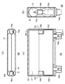
한편, 하기 특허문헌 1에는, 양극극판 및 음극극판이 세퍼레이터를 사이에 두고 편평상(扁平狀)으로 권회된 전극체에 있어서, 세퍼레이터로부터 비어져 나와 있는 각각의 전극의 심체 노출부의 적층폭을 작게 하기 위해서, 각각의 전극의 심체 노출부를 2개소씩 나누어 집전부재에 용접한 축전소자의 발명이 개시되어 있다. 여기서 하기 특허문헌 1에 개시되어 있는 축전소자의 구성을 도 9 및 도 10을 이용하여 설명한다. 또한, 도 9의 (A)는 하기 특허문헌 1에 개시되어 있는 축전소자로서의 전기이중층 캐패시터의 단면도이며, 도 9의 (B)는 도 9의 (A)의 ⅨB-ⅨB선을 따른 단면도이며, 도 9의 (C)는 도 9의 (A)의 ⅨC-ⅨC을 따른 단면도이다. 또한, 도 (10)은 도 9에 있어서의 전극의 심체 노출부와 집전부재와의 사이의 용접공정을 나타내는 도면이다.On the other hand, Patent Literature 1 below discloses an electrode body in which an anode plate and a cathode plate are wound in a flat shape with a separator interposed therebetween, so that the stacking width of the core exposed portion of each electrode protruding from the separator is small. To this end, the invention of a power storage element in which two core exposed portions of each electrode are welded to a current collector member is disclosed. Here, the structure of the electrical storage element disclosed by following patent document 1 is demonstrated using FIG. 9 and FIG. 9A is a cross-sectional view of an electric double layer capacitor as a power storage element disclosed in Patent Document 1 below, and FIG. 9B is a cross-sectional view taken along the line BB-BB of FIG. 9A. FIG. 9C is a cross-sectional view taken along XXC-XC of FIG. 9A. 10 is a figure which shows the welding process between the core exposed part of an electrode, and a collector member in FIG.
이 축전소자(50)는, 도 9의 (A) 내지 도 9의 (C)에 나타낸 것과 같이, 양극극판 및 음극극판이 세퍼레이터(어디에도 도시하지 않음)를 사이에 두고 적층되어 편평상으로 권회된 권회전극체(51)를 구비하고 있으며, 이 권회전극체(15)는 각형의 알루미늄제의 외장케이스(52) 내에 배치되어 있다. 또한, 이 축전소자(50)의 양극용 집전부재(53a) 및 음극용 집전부재(53b)는, 각각 일방측의 단부에 コ자형상의 날개부(54a 내지 54b)가 형성되고, 각각 양극극판의 심체 노출부(55a) 내지 음극극판의 심체 노출부(55b)에 접속되며, 타방측의 단부는 각각 양극단자(56a) 내지 음극단자(56b)에 접속되어 있다. 그리고, 양극극판의 심체 노출부(55a)는 묶여져 2분할되고, 각각 일방의 コ자형상의 날개부(54a)의 외면측의 2개소에 용접되고 있으며, 또한, 음극극판의 심체 노출부(55b)도 2분할되어 각각 타방의 コ자형상의 날개부(54b)의 외면측의 2개소에 용접되어 있다.As shown in Figs. 9A to 9C, the
이 용접은, 예를 들면 양극극판측이면, 도 10에 나타낸 것과 같이, 2분할된 양극극판의 심체 노출부(55a) 중 일방을 コ자형상의 날개부(54a)의 외면에 배치하고, 이 심체 노출부(55a)의 외표면에 초음파 용접장치(도시 생략)의 혼(57, horn)을 맞닿게 하며, コ자형상의 날개부(54a)의 내면측에 앤빌(58, anvil)을 배치하는 것에 의해, 초음파 용접이 행하여지고 있다. 또한, 2분할된 양극극판의 심체 노출부(55a)의 타방에 대해서도 동일한 방법으로 초음파 용접이 행하여지고 있으며, 또한, 음극극판측에 있어서도 마찬가지이다. In this welding, for example, on the positive electrode side, one of the core exposed
한편, 2분할한 양극극판 혹은 음극극판을 저항용접하는 경우는, 분할한 시트 한쪽 면씩 용접하는 방법, 또한, 분할한 시트를 동시에 용접하는 시리즈 스폿용접이 검토되고 있지만, 용접회수의 삭감을 고려하면 시리즈 스폿용접이 바람직하다. 종래의 시리즈 스폿용접 기술에서는, 도 11에 나타내는 것과 같이, 용접용의 한 쌍의 저항용접용 전극봉(71 및 72)과 동축상에서 피용접부재(73 및 74)를 2점 용접하는 경우에는, コ자형상의 용접용 부품(75)을 중간에 개재시키고, コ자형상의 용접용 부품(75)의 상하를 용접하는 방법이 주로 이용되고 있었다. 이 방법은, コ자형상의 용접용 부품(75)은, 판상(板狀)의 금속판으로부터 용이하게 제작할 수 있다는 점, 저항용접을 용이하고 안정화시키기 위한 프로젝션의 제작이 용이한 점 때문에 널리 일반적으로 이용되고 있다.On the other hand, in the case of resistance welding of two-divided positive electrode plates or negative electrode plates, a method of welding one side of the divided sheets and a series spot welding of simultaneously welding the divided sheets are considered, but considering the reduction in the number of welding times, Series spot welding is preferred. In the conventional series spot welding technique, as shown in FIG. 11, when two-point welding of the to-be-welded
상기 특허문헌 1에 개시되어 있는 발명에 의하면, 양극심체 노출부 및 음극심체 노출부의 노출폭을 작게 할 수 있기 때문에, 축전장치의 용적효율이 양호해진다고 하는 효과를 발휘한다. 그러나, 이 발명은 양극극판 내지 음극극판에 양극용 집전부재 내지 음극용 집전부재를 용접하기 위해서는 각각 복수회의 용접이 필요하게 되며, 또한 권회 전극체의 중앙부에는 용접하기 위한 양극용 집전부재 내지 음극용 집전부재의 コ자형상의 날개부를 배치하기 위한 개구공간을 필요로 한다는 점, 초음파 용접시에 コ자형상의 날개부의 내부에 앤빌을 배치할 필요가 있다는 점 등, 제조 설비가 복잡화한다고 하는 문제점이 존재하고 있다.According to the invention disclosed in Patent Document 1, since the exposure width of the positive electrode core exposed portion and the negative electrode core exposed portion can be reduced, the volumetric efficiency of the power storage device is improved. However, in the present invention, a plurality of weldings are required in order to weld the positive electrode current collector member or the negative electrode current collector member to the positive electrode plate or the negative electrode plate, and at the center of the wound electrode body, the positive electrode current collector member to the negative electrode is welded. There are problems such as complicated manufacturing facilities, such as the need for an opening space for arranging the U-shaped wings of the current collecting member, and the need for an anvil to be placed inside the U-shaped wings during ultrasonic welding. have.
또한, 상기 특허문헌 1에는, 전극극판을 접속하는 공정은 초음파 용접법을 이용하는 것이 특히 바람직하다고 기재되어 있지만, 실시예에서의 권회수는 16회(2 분할한 한쪽 측에서는 8회)이며, 적층두께는 320 ㎛로 되어 있다. 그것에 대해, EV, HEV용의 리튬이온 2차전지 등의 용량이 큰 밀폐전지에서는, 양극심체 노출부 및 음극심체 노출부의 적층 매수는 상기 특허문헌 1에 개시되어 있는 발명의 경우보다 매우 많아지고 있음과 아울러, 적층 두께도 매우 두꺼워지고 있다.In addition, although the process of connecting an electrode plate is mentioned in the said patent document 1, it is especially preferable to use the ultrasonic welding method, The winding number in an Example is 16 times (8 times on one side divided into two), and the laminated thickness is It is 320 micrometers. On the other hand, in a sealed battery having a large capacity such as a lithium ion secondary battery for EV and HEV, the number of stacked sheets of the positive electrode core exposed portion and the negative electrode core exposed portion is much larger than in the case of the invention disclosed in Patent Document 1 above. In addition, the lamination thickness is also very thick.
이 때문에, EV, HEV용의 리튬이온 이차전지 등의 용량이 큰 각형 밀폐 2차전지에서는, 적층된 양극심체 노출부 및 음극심체 노출부와 집전부재와의 사이의 용접방법으로서 초음파 용접법을 채용하여 안정된 상태로 용접하기 위해서는, 적층된 양극심체 노출부 및 음극심체 노출부를 각각 집전부재에 밀착시키기 위한 큰 가압과, 초음파 진동을 적층된 양극심체 노출부 및 음극심체 노출부의 타단측까지 도달시키기 위한 큰 에너지가 필요하다. 상기 특허문헌 1에 개시되어 있는 발명에서는, コ자형상의 집전재의 내부에 배치된 앤빌에서 가압 및 초음파 에너지를 받을 필요가 있기 때문에, 앤빌에 상응하는 강성이 필요하며, 게다가, コ자형상의 집전부재의 내부에 공급할 수 있는 크기의 앤빌에서 큰 가압을 받으면서 더욱 안정된 용접조건을 찾아내는 것은 기술적으로 매우 곤란하다.For this reason, in a rectangular sealed secondary battery having a large capacity such as a lithium ion secondary battery for EV and HEV, an ultrasonic welding method is employed as a welding method between the stacked positive electrode core exposed portion and negative electrode core exposed portion and the current collector member. In order to weld in a stable state, a large press for closely contacting the laminated core core exposed portion and the negative electrode core exposed portion to the current collector member and a large pressure for reaching ultrasonic wave vibration to the other end side of the laminated anode core exposed portion and the cathode core exposed portion, respectively. Energy is needed. In the invention disclosed in Patent Document 1, since it is necessary to receive pressurized and ultrasonic energy from an anvil disposed inside the U-shaped current collector, rigidity corresponding to the anvil is required, and furthermore, a U-shaped current collector member. It is technically very difficult to find a more stable welding condition under a large pressurization in anvil sized to be able to supply inside of the engine.
또한, 도 11에 나타낸 종래 방법에서는, 한 번의 용접으로 양극심체 노출부 및 음극심체 노출부의 각각에 대해서 시리즈 용접할 수 있지만, 용접용의 전극봉(71 및 72)에 의한 가압에 의한 コ자형상의 용접용 부품(75)의 변형을 없애기 위해서, コ자형상의 용접용 부품의 내부에 가압받이(76)나 통전용으로서 금속 블록의 공급을 행하는 등의 대책이 필요하게 되어 용접 설비의 복잡화라는 과제가 있었다.In the conventional method shown in Fig. 11, series welding can be performed on each of the positive electrode core exposed portion and the negative electrode core exposed portion by one welding, but the U-shaped welding by pressurization by the
또한, 상기 특허문헌 2에는, 도 12에 나타낸 것처럼, 집전부재(81)의 기초부(82)의 양측에 전극체(83)의 심체(84)를 2개로 분할하여 집속한 전극 심체군(84a 및 84b)을 맞닿게 하고, 이들 전극 심체군(84a 및 84b)의 외측에 배치한 한 쌍의 맞닿음판(85a 및 85b)과 함께 일체로 시리즈 스폿 용접한 극판심체 집결장치(80)가 개시되어 있다. In Patent Document 2, as shown in FIG. 12, the electrode core group 84a in which the
또한, 상기 특허문헌 3에는, 도 13의 (A) 및 도 13의 (B)에 나타내는 바와 같이, 양극극판 및 음극극판이 각각 세퍼레이터를 사이에 두고, 양극심체 노출부(91) 및 음극심체 노출부(92)가 각각 반대 측에 배치되도록, 권회된 편평상의 권회전극체(93)를 구비하며, 예를 들면 양극심체 노출부(91)의 권회된 중앙공간(91a)에 끼워 맞춤되는 가장자리부분이 곡면형상으로 된 직사각형 형상의 접속부(94a)와, 권회축방향과 직교하는 편평축 길이방향으로 돌출하는 단자부(94b)와, 양자를 연결하는 짧은 연결부(94c)를 구비하는 양극단자(94)를 이용하고, 이 양극단자(94)의 단자부(94b)를 양극심체 노출부(91)의 권회된 중앙공간(91a)에 끼워맞춘(도 13의 (A) 참조) 후, 양극심체 노출부(91)의 양측으로부터 시리즈 스폿 용접하는 것에 의해 전기적으로 접속하도록 한 편평 권회 전극전지(90)가 개시되어 있다.In Patent Document 3, as shown in Figs. 13A and 13B, the positive electrode plate and the negative electrode plate respectively have a separator interposed therebetween to expose the positive electrode core exposed
하지만, 상기 특허문헌 2 및 3에 개시되어 있는 시리즈 스폿 용접법에서는, 양극극판 내지 음극극판의 심체 노출부는, 2분할되어 직접 양극단자 내지 음극단자의 양측으로부터 시리즈 스폿 용접되고 있지만, 양극단자 내지 음극단자의 용접면은 평탄면으로 되어 있기 때문에, 양극단자 내지 음극단자와 양극극판 내지 음극극판의 심체 노출부와의 사이의 용접강도를 높게 함과 아울러 용접부의 내부저항의 편차를 작게 하는 것은 곤란했다.However, in the series spot welding method disclosed in the patent documents 2 and 3, the core exposed portion of the positive electrode plate or the negative electrode plate is divided into two parts and the series spot welding is directly performed from both sides of the positive electrode terminal to the negative electrode terminal. Since the welding surface of is a flat surface, it was difficult to increase the welding strength between the positive electrode terminal and the negative electrode terminal and the core exposed portion of the positive electrode plate and the negative electrode plate, and to reduce the variation in the internal resistance of the weld portion.
또한, EV, HEV용의 리튬이온 2차전지 등의 용량이 큰 각형 밀폐 2차전지의 경우에는, 양극심체 노출부 및 음극심체 노출부의 적층매수가 매우 많게 되며, 또한, 양극심체 및 양극 집전체로서는 알루미늄 또는 알루미늄합금이, 음극심체 및 음극 집전체로서는 동 또는 동합금 등이 이용된다. 이들 알루미늄 또는 알루미늄합금이나 동 또는 동합금은 전기저항이 작고, 게다가 열전도율도 양호한 재료이기 때문에, 양극심체 노출부와 양극단자와의 사이 및 음극심체 노출부와 음극단자와의 사이의 용접강도를 높게 함과 아울러 용접부의 내부저항을 작게 하는 것은 보다 곤란하게 된다. In addition, in the case of a rectangular sealed secondary battery having a large capacity such as a lithium ion secondary battery for EV and HEV, the number of stacks of the positive electrode core exposed portion and the negative electrode core exposed portion becomes very large, and the positive electrode core and the positive electrode current collector As an aluminum or aluminum alloy, as a negative electrode core and a negative electrode collector, copper or a copper alloy etc. are used. Since these aluminum or aluminum alloys, copper or copper alloys have low electrical resistance and good thermal conductivity, the welding strength between the positive electrode core exposed portion and the positive electrode terminal and between the negative electrode core exposed portion and the negative electrode terminal is increased. In addition, it is more difficult to reduce the internal resistance of the welded portion.
본 발명은, 상기와 같은 종래 기술의 문제점을 해결하기 위하여 이루어진 것으로, 적층된 양극심체 노출부 및 음극심체 노출부의 적어도 일방측의 심체 노출부는 2분할되며, 그 사이에 연결도전부재가 안정적으로 위치결정 배치되어 심체 노출부와 집전부재와의 사이 및 심체 노출부와 연결도전부재와의 사이가 저항용접된, 용접부의 저저항화를 실현할 수 있으며 게다가, 용접강도의 편차가 억제된 각형 밀폐 2차전지 및 그 제조방법을 제공하는 것을 목적으로 한다. The present invention has been made to solve the problems of the prior art as described above, wherein the core exposed portion of at least one side of the stacked core core exposed portion and the cathode core exposed portion is divided into two portions, and the connection conductive member is stably positioned therebetween. It is possible to realize a low resistance of the welded portion in which the crystal is disposed and resistance welded between the core exposed portion and the current collector member and between the core exposed portion and the connecting conductive member, and furthermore, a rectangular sealed secondary in which the variation in welding strength is suppressed. It is an object to provide a battery and a method of manufacturing the same.
상기 목적을 달성하기 위해서, 본 발명의 각형 밀폐 2차전지는, 적층 내지 권회된 양극심체 노출부 및 음극심체 노출부를 가지는 전극체와, 상기 양극심체 노출부에 전기적으로 접합되어 있는 집전부재와, 상기 음극심체 노출부에 전기적으로 접합되어 있는 집전부재를 구비한 각형 밀폐 2차전지로서, 상기 양극심체 노출부 및 상기 음극심체 노출부의 적어도 일방은, 2분할되고 그 사이에 복수의 연결도전부재를 유지한 수지재료제의 중간부재가 배치되며, 상기 2분할된 심체 노출부측의 상기 집전부재는, 상기 2분할된 심체 노출부의 최외측의 적어도 일방의 면에 배치되며, 상기 2분할된 심체 노출부와 상기 중간부재의 상기 복수의 연결도전부재와 함께 저항용접법에 의해서 전기적으로 접합되어 있는 것을 특징으로 한다.In order to achieve the above object, the rectangular sealed secondary battery of the present invention, an electrode body having a laminated core wound and a positive electrode core exposed portion and a negative electrode core exposed portion, a current collector member electrically connected to the positive electrode core exposed portion, A rectangular sealed secondary battery having a current collector member electrically connected to a negative electrode core exposed portion, wherein at least one of the positive electrode core exposed portion and the negative electrode core exposed portion is divided into two to hold a plurality of connection conductive members therebetween. An intermediate member made of a resin material is disposed, and the current collector member on the two-divided core exposed portion side is disposed on at least one surface of the outermost portion of the two-divided core exposed portion, and the two-divided core exposed portion And the plurality of connection conductive members of the intermediate member are electrically joined by a resistance welding method.
본 발명의 각형 밀폐 2차전지에 있어서, 양극심체 노출부 및 음극심체 노출부의 적어도 일방의 2분할되 쪽에는, 2분할된 그 사이에 복수의 연결도전부재를 유지한 수지재료제의 중간부재가 배치되어 있다. 그리고, 2분할된 심체 노출부측의 집전부재는, 2분할된 심체 노출부의 최외측의 적어도 일방의 면에 배치되며, 2분할된 심체 노출부와 중간부재의 복수의 연결도전부재와 함께 저항용접법에 의해서 전기적으로 접합되어 있다.In the rectangular sealed secondary battery of the present invention, at least one of the positive electrode core exposed portion and the negative electrode core exposed portion is divided into two, and an intermediate member made of a resin material which holds a plurality of connection conductive members therebetween is divided into two. It is arranged. The current collector member on the two-sided core exposed portion side is disposed on at least one surface of the outermost portion of the two-sided core exposed portion, and is subjected to resistance welding together with the plurality of connection conductive members of the two-sided core exposed portion and the intermediate member. It is electrically bonded by.
이 때문에, 본 발명의 각형 밀폐 2차전지에 의하면, 시리즈 저항용접법에 의해서, 2분할된 측의 심체 노출부와 연결도전부재 및 집전부재와의 사이를 한 번에 접합할 수 있다. 이에 더하여, 복수의 연결도전부재는 수지재료제의 중간부재에 유지되어 있기 때문에, 복수의 연결도전부재 사이의 치수 정밀도가 향상되고, 게다가, 2분할된 측의 심체 노출부의 사이에 안정된 상태로 위치결정 배치할 수 있기 때문에, 저항용접부의 품질이 향상되고 저저항화를 실현할 수 있다. 이 때문에, 본 발명의 각형 밀폐 2차전지에 의하면, 출력이 향상되고, 게다가, 출력의 편차가 저감된 각형 밀폐 2차전지가 얻어진다.For this reason, according to the rectangular sealed secondary battery of the present invention, it is possible to join the core exposed portion on the two-divided side with the connection conductive member and the current collector member at one time by the series resistance welding method. In addition, since the plurality of connection conductive members are held in the intermediate member made of resin material, the dimensional accuracy between the plurality of connection conductive members is improved, and furthermore, they are positioned in a stable state between the core exposed portions on the two divided sides. Since the crystals can be arranged, the quality of the resistance welding portion can be improved and the resistance can be reduced. For this reason, according to the rectangular sealed secondary battery of this invention, an output improves and also the square sealed secondary battery by which the variation of an output was reduced is obtained.
또한, 본 발명의 2분할된 심체 노출부측의 집전부재는, 2분할된 심체 노출부의 최외측의 적어도 일방의 면에 배치되어 있으면 되지만, 2분할된 심체 노출부의 최외측의 양쪽의 면에 배치되어 있는 것이 바람직하다. 다만, 2분할된 심체 노출부의 최외측의 타방의 면에는 전극단자에 직접 접속되어 있지 않은 집전받이부재를 배치하여도, 실질적으로 집전부재를 2분할된 심체 노출부의 최외측의 양쪽 면에 배치했을 경우와 동일한 작용 효과를 발휘할 수 있다. 이 때문에, 본 발명에 있어서의 「집전부재」는 이와 같은 「집전받이부재」도 포함하는 의미에서 이용되고 있다. Further, the current collector member on the two-divided core exposed portion side of the present invention may be disposed on at least one surface of the two-divided core exposed portion, but disposed on both outermost sides of the two-divided core exposed portion. It is desirable to have. However, even if a current collector member not directly connected to the electrode terminal is disposed on the other side of the outermost part of the core-exposed part divided into two parts, the current collector member may be substantially disposed on both sides of the outermost part of the core-exposed part divided into two parts. The same effects as in the case can be obtained. For this reason, the "current collecting member" in the present invention is used in the sense including such a "current collecting member".
또한, 저항용접은, 집전부재를 2분할된 심체 노출부의 최외측의 양쪽 면에 배치한 것이 물리적으로 안정한 상태에서 행할 수 있다. 또한, 2분할된 심체 노출부의 최외측의 타방의 면에는, 아무것도 배치하지 않고 직접 한 쌍의 저항용접용 전극의 일방을 맞닿게 하여 저항용접하는 것도 가능하다. 그렇지만, 이 경우는, 저항용접용 전극과 2분할된 심체 노출부의 타방의 면과의 사이에 융착이 발생할 가능성이 있으므로, 2분할된 심체 노출부의 최외측의 양쪽 면에 각각 전극단자에 접속된 집전부재를 배치하거나, 일방측의 면에 전극단자에 접속된 집전부재를 배치함과 아울러 타방측의 면에 집전받이부재로서의 집전부재를 배치하는 것이 바람직하다.In addition, resistance welding can be performed in the state in which the collector member was arrange | positioned at the outermost both surfaces of the core part which divided | segmented into two, and is physically stable. In addition, it is also possible to perform resistance welding by directly contacting one of the pair of resistance welding electrodes without placing anything on the other side of the outermost part of the core exposed portion divided into two parts. In this case, however, fusion may occur between the electrode for resistance welding and the other surface of the core exposed portion divided into two parts, so that current collectors connected to the electrode terminals on both outermost surfaces of the two divided core exposed portions, respectively. It is preferable to arrange | position a member, or to arrange | position the collector member connected to the electrode terminal in the surface on one side, and arrange | position a collector member as a collector member on the other surface.
또한, 본 발명의 각형 밀폐 2차전지의 중간부재에 사용할 수 있는 수지재료로서는, 예를 들면 폴리프로필렌(PP), 폴리에틸렌(PE), 폴리염화비닐리덴(PVDC), 폴리아세탈(POM), 폴리아미드(PA), 폴리카보네이트(PC), 폴리페닐렌설파이드(PPS) 등을 들 수 있다.As the resin material which can be used for the intermediate member of the rectangular sealed secondary battery of the present invention, for example, polypropylene (PP), polyethylene (PE), polyvinylidene chloride (PVDC), polyacetal (POM), poly Amide (PA), polycarbonate (PC), polyphenylene sulfide (PPS), etc. are mentioned.
또한, 본 발명의 각형 밀폐 2차전지에 있어서는, 상기 중간부재는 구멍 및 노치 중 적어도 일방을 구비하고 있는 것이 바람직하다.Moreover, in the rectangular sealed secondary battery of this invention, it is preferable that the said intermediate member is equipped with at least one of a hole and a notch.
중간부재에 구비된 구멍이나 노치는, 전지에 이상이 생겨 가스가 전극체 내부에 발생했을 때, 가스를 전극체의 외부로 배출하는 가스빼기용의 루트로서 기능한다. 따라서, 중간부재가 구멍이나 노치를 구비하고 있으면, 전극체 내부에 가스가 발생하여도 용이하게 전극체의 외부로 배출할 수 있으며, 각형 밀폐 전지에 보통 구비되어 있는 감압식 전류차단기구나 가스배출밸브 등이 안정적으로 동작하므로, 안전성을 확보할 수 있다. 이에 더하여, 중간부재의 체적이 감소하므로, 각형밀폐 전지를 가볍게 할 수 있게 된다.The hole or notch provided in the intermediate member functions as a route for outgasing the gas to be discharged to the outside of the electrode body when an abnormality occurs in the battery and gas is generated inside the electrode body. Therefore, if the intermediate member is provided with a hole or notch, even if gas is generated inside the electrode body, it can be easily discharged to the outside of the electrode body, and a pressure-sensitive current cut-off device or a gas discharge valve which is usually provided in a rectangular sealed battery, etc. Since this stable operation, safety can be secured. In addition, since the volume of the intermediate member is reduced, the square sealed battery can be made light.
또한, 본 발명의 각형 밀폐 2차전지에 있어서는, 상기 중간부재는, 상기 중간부재에 있어서의 적어도 한 쌍의 대향하는 측면에 각각 상기 중간부재의 삽입 방향과 평행한 노치를 구비하고 있는 것으로 할 수 있다.In the rectangular sealed secondary battery of the present invention, the intermediate member may be provided with notches parallel to the insertion direction of the intermediate member on at least one pair of opposing side surfaces of the intermediate member. have.
이와 같은 구성을 채용하면, 제조 공정에 있어서의 중간부재의 2분할된 심체 노출부의 사이로의 삽입 및 집전체 저항용접시 노치를 통하여 위치결정용 치구나 암(arm)에 의한 중간부재의 파지를 보다 안정시킬 수 있으며, 더욱이, 노치가 중간부재의 삽입방향과 평행하게 형성되어 있기 때문에, 위치결정용 치구나 암에 의한 중간부재의 파지나 제거를 부드럽게 행할 수 있다. 따라서, 중간부재와 전극체와의 위치어긋남이나 기울어짐이 방지되어 집전체 용접의 용접신뢰성이나 제품의 수율을 향상시킬 수 있으며, 이에 더하여 중간부와 위치결정용 치구 내지 암은 서로 끼워지는 것만으로 확실하게 양자가 고정되기 때문에 제조설비의 간소화가 가능하게 된다. By adopting such a configuration, the intermediate member in the manufacturing process is inserted between the two divided core exposed portions, and the grip of the intermediate member by the positioning jig or arm through the notch during the current collector resistance welding. Since the notch is formed in parallel with the insertion direction of the intermediate member, the gripping and removal of the intermediate member by the positioning jig or arm can be performed smoothly. Therefore, shifting or inclination of the intermediate member and the electrode body can be prevented, thereby improving the welding reliability of the current collector welding or the yield of the product. In addition, the intermediate part and the positioning jig or arm are simply fitted together. Since both are securely fixed, the manufacturing equipment can be simplified.
또한, 중간부재의 삽입방향과 평행하게 형성되는 노치는, 위치결정용 치구나 암에 의한 파지의 안정성의 견지에서 중간부재에 있어서의 한 쌍의 대향하는 측면에 각각 마련되어 있는 것이 바람직하며, 또한 중간부재의 위치결정 및 집전체 저항용접시에, 위치결정용 치구 내지 암과 양극심체 노출부와의 간섭을 극력 적게 하기 위해서 중간부재의 심체 노출부와 대향하지 않는 면, 즉, 연결도전부재가 돌출하고 있는 면과는 다른 면에 마련하는 것이 바람직하다.In addition, the notch formed in parallel with the insertion direction of the intermediate member is preferably provided on a pair of opposing side surfaces of the intermediate member in view of the stability of the grip by the positioning jig or arm. In positioning the member and welding the current collector resistance, the surface that does not face the core exposed portion of the intermediate member, that is, the connection conductive member protrudes in order to minimize the interference between the positioning jig and the arm and the core exposed portion. It is preferable to provide it in the surface different from the surface currently made.
또한, 본 발명의 각형 밀폐 2차전지에 있어서는, 상기 중간부재는 각부가 모따기되어 있는 것이 바람직하다.In the rectangular sealed secondary battery of the present invention, the intermediate member is preferably chamfered.
본 발명의 각형 밀폐 2차전지에 의하면, 중간부재의 각부가 모따기되어 있으므로, 중간부재를 적층된 심체 노출부의 사이에 삽입할 때에, 모따기되어 있는 중간부재가 유연한 심체 노출부와 접촉하여도 심체 노출부에 손상을 주는 것이 적게 되어, 용이하게 복수의 연결도전부재를 심체 노출부와 맞닿게 할 수 있도록 되기 때문에, 용접성이 향상된다.According to the rectangular sealed secondary battery of the present invention, since the corner portions of the intermediate member are chamfered, when the intermediate member is inserted between the stacked core exposed portions, the core member is exposed even when the chamfered intermediate members come into contact with the flexible core exposed portions. The damage to the parts is reduced, and the plurality of connection conductive members can be easily brought into contact with the core exposed portion, thereby improving weldability.
또한, 본 발명의 각형 밀폐 2차전치에 있어서는, 상기 연결도전부재는 블록 형상 또는 주상체(柱狀體) 형상인 것이 바람직하다.In the rectangular hermetically sealed secondary tooth of the present invention, it is preferable that the connection conductive member is in the shape of a block or columnar body.
본 발명의 각형 밀폐 2차전지에 의하면, 연결도전부재가 블록형상 또는 주상체 형상으로 되어 있으므로, 저항용접시에 압압력을 인가하여도 변형하기 어렵게 되며, 용접부분의 물성이 안정화되고, 게다가, 용접부분의 품질이 양호해진다.또한, 연결도전부재의 형상으로서는, 원주상(圓柱狀), 각주상(角柱狀), 타원주상(楕圓柱狀), 원통상(圓筒狀), 각통상(角筒狀), 타원통상(楕圓筒狀) 등의 변형하기 어려운 형상인 것을 채용할 수 있다.According to the rectangular sealed secondary battery of the present invention, since the connection conductive member has a block shape or columnar body shape, it is difficult to deform even when a pressure is applied during resistance welding, and the physical properties of the welded part are stabilized. The quality of the welded portion is good. [0049] Further, the shape of the connection conductive member may include a columnar shape, a columnar shape, an elliptic columnar shape, a cylindrical shape, and a cylindrical shape. (I) A shape that is difficult to deform, such as an elliptic cylinder, can be adopted.
또한, 본 발명의 각형 밀폐 2차전지에 있어서는, 상기 블록형상 또는 주상체 형상의 서로 대향하는 2개의 면의 각부가 모따기되어 있는 것이 바람직하다.Moreover, in the rectangular sealed secondary battery of this invention, it is preferable that the corner part of the two surface which mutually opposes the said block shape or columnar body shape is chamfered.
본 발명의 각형 밀폐 2차전지에 의하면, 블록형상 또는 주상체 형상의 서로 대향하는 2개의 면의 각부가 모따기되어 있으면, 중간부재가 적층된 심체 노출부의 사이에 삽입할 때에, 연결도전부재가 유연한 심체 노출부와 접촉하여 심체 노출부에 손상을 주는 것이 적어지며, 용이하게 복수의 연결도전부재를 심체 노출부와 맞닿게 할 수 있도록 되기 때문에, 용접성이 향상된다. 게다가, 연결도전부재의 대향하는 2개의 면 각각의 면적이 작아지기 때문에, 연결도전부재의 대향하는 2개의 면은 프로젝션으로서 작용하므로, 전류가 집중하여 발열하기 쉽게 되며, 용접부분의 물성이 안정화되고, 게다가, 용접부분의 품질이 양호하게 된다.According to the rectangular sealed secondary battery of the present invention, when the corner portions of the two surfaces facing each other in a block shape or columnar shape are chamfered, the connection conductive member is flexible when the intermediate member is inserted between the stacked core exposed portions. The contact with the core exposed portion is less likely to damage the core exposed portion, and the weldability is improved because the plurality of connection conductive members can be easily brought into contact with the core exposed portion. In addition, since the area of each of the two opposite surfaces of the connection conductive member becomes smaller, the two opposite surfaces of the connection conductive member act as projections, so that current is concentrated and heat is easily generated, and the properties of the welded portion are stabilized. In addition, the quality of the welded part becomes good.
또한, 본 발명의 각형 밀폐 2차전지에 있어서는, 상기 연결도전부재의 상기 모따기되어 있는 면은 평면으로 되어 있는 것이 바람직하다.In the rectangular sealed secondary battery of the present invention, the chamfered surface of the connection conductive member is preferably flat.
복수의 연결도전부재의 모따기되어 있는 면은 곡면 및 평면의 양태양을 취할 수 있다. 그렇지만, 모따기되어 있는 면를 평면으로 하면, 중간부재를 적층된 심체 노출부의 사이에 삽입했을 때에, 각부를 모따기되어 있는 면과 중간부재에 있어서의 연결도전부재가 노출한 면과의 사이가 심체 노출부에 대해서 반드시 둔각이 된다. 이 때문에, 본 발명의 각형 밀폐 2차전지에 의하면, 중간부재를 적층된 심체 노출부의 사이에 삽입하여 저항용접 할 때, 심체 노출부와 복수의 연결도전부재가 접촉하기 쉬워지므로, 용접성이 향상한다.The chamfered surface of the some connection conductive member can take both aspects of a curved surface and a plane. However, when the chamfered surface is made flat, when the intermediate member is inserted between the laminated core exposed portions, the core exposed portion is formed between the surface chamfered and the surface exposed by the connecting conductive member in the intermediate member. Will always be obtuse. For this reason, according to the rectangular sealed secondary battery of the present invention, when the intermediate member is inserted between the laminated core exposed portions and subjected to resistance welding, the core exposed portion and the plurality of connection conductive members are easily contacted, thereby improving weldability. .
게다가 상기 목적을 달성하기 위해, 본 발명의 각형 밀폐 2차전지의 제조방법은, 이하의 (1) 내지 (5)의 공정을 포함하는 것을 특징으로 한다.Moreover, in order to achieve the said objective, the manufacturing method of the rectangular sealed secondary battery of this invention is characterized by including the process of the following (1)-(5).
(1) 양극극판과 음극극판을 세퍼레이터를 사이에 두고 적층 또는 권회함으로써 일방의 단부에 복수매 적층된 양극심체 노출부가 형성되며, 타방의 단부에 복수매 적층된 음극심체 노출부가 형성된 편평모양 전극체를 제작하는 공정,(1) A positive electrode core exposed portion formed by stacking or winding a positive electrode plate and a negative electrode plate with a separator interposed therebetween, and having a negative electrode core exposed portion laminated on a plurality of sheets at the other end. Manufacturing process,
(2) 상기 적층된 양극심체 노출부 및 음극심체 노출부의 적어도 일방을 2분할하는 공정,(2) dividing at least one of the laminated positive electrode core exposed portion and negative electrode core exposed portion into two;
(3) 상기 2분할된 심체 노출부의 최외측의 양표면에 집전체 부재를 배치함과 아울러, 상기 2분할된 심체 노출부의 사이에, 복수의 연결도전부재를 유지한 수지재료제의 중간부재를 배치하고, 상기 연결도전부재의 대향하는 2개의 면 각각이 상기 2분할된 심체 노출부와 접하도록 배치하는 공정,(3) An intermediate member made of a resin material having a current collector member disposed on both outermost surfaces of the two-divided core-exposed portion, and holding a plurality of connection conductive members between the two-divided core-exposed portions. Arranging each of the two opposite surfaces of the connection conductive member to be in contact with the divided body exposed portion;
(4) 상기 2분할된 심체 노출부의 최외측의 양표면에 배치되어 있는 상기 집전부재에 한 쌍의 저항용접용 전극을 맞닿게 하는 공정,(4) a step of bringing a pair of resistance welding electrodes into contact with the current collector members disposed on both outermost surfaces of the two divided core exposed portions;
(5) 상기 한 쌍의 저항용접용 전극 사이에 압압력을 인가하면서 저항용접을 행하는 공정.(5) A step of performing resistance welding while applying a pressing force between the pair of resistance welding electrodes.
본 발명의 각형 밀폐 2차전지의 제조방법에 있어서는, 적층된 양극심체 노출부 및 음극심체 노출부의 적어도 일방을 각각 2분할하고, 이 양극심체 노출부 내지 음극심체 노출부의 최외측의 양표면에 집전부재를 배치하며, 2분할된 심체 노출부 사이에 복수의 연결도전부재를 유지한 수지재료제의 중간부재를, 연결도전부재의 대향하는 2개의 면 각각이 상기 2분할된 심체 노출부와 접하도록 배치하고, 상기 2분할된 심체 노출부의 최외측의 양표면에 배치되어 있는 집전부재에 한 쌍의 저항용접용 전극을 맞닿게 하며, 한 쌍의 저항용접용 전극 사이에 압압력을 인가하면서 저항용접을 행하는 공정을 포함하고 있다. 이와 같은 저항용접공정에서는, 저항용접전류는, 2분할된 쪽의 심체 노출부측에서는, 집전부재 -> 심체 노출부 -> 연결도전부재 -> 심체 노출부 -> 집전부재로 흐르므로, 한 번의 저항항접으로 집전부재와 심체 노출부 사이, 심체 노출부와 도전연결부재 사이를 동시에 용접할 수 있다. In the manufacturing method of the rectangular sealed secondary battery of the present invention, at least one of the laminated positive electrode core exposed portion and the negative electrode core exposed portion is divided into two, and the current collector is collected on both outermost surfaces of the positive electrode core exposed portion and the negative electrode core exposed portion. A member is disposed, and an intermediate member made of a resin material holding a plurality of connection conductive members between the two divided core exposed portions so that each of two opposite surfaces of the connection conductive member contacts the two divided core exposed portions. And a pair of resistance welding electrodes abut on a current collector member disposed on both outermost surfaces of the two-divided core exposed portion, and applying resistance pressure while applying a pressure force between the pair of resistance welding electrodes. The process of performing this process is included. In such a resistance welding process, the resistance welding current flows from the current collector member-> core exposed part-> connection conductive member-> core exposed part-> current collector member on the two-sided core exposed part side. It is possible to simultaneously weld between the current collector member and the core exposed portion, and the core exposed portion and the conductive connecting member by the welding.
게다가, 복수의 연결도전부재는 수지재료제의 중간부재에 유지되고 있기 때문에, 복수의 연결도전부재 사이의 치수정밀도가 향상되고, 게다가, 2분할된 양극심체 노출부 내지 음극심체 노출부의 사이에 안정된 상태에서 위치결정 배치할 수 있기 때문에, 저항용접부의 품질이 향상되며 저저항화를 실현할 수 있다. 이 때문에, 본 발명의 각형 밀폐 2차전지에 의하면, 출력이 향상되며, 게다가, 출력의 편차가 저감된 각형 밀폐 2차전지를 얻을 수 있다.In addition, since the plurality of connection conductive members are held by the intermediate member made of resin material, the dimensional accuracy between the plurality of connection conductive members is improved, and further, it is stable between the two divided anode core exposed portions and cathode core exposed portions. Since positioning can be performed in a state, the quality of the resistance welding portion can be improved, and the resistance can be reduced. For this reason, according to the square sealed secondary battery of this invention, an output improves and the square sealed secondary battery which the output variation was reduced can also be obtained.
이에 더하여, 본 발명의 각형 밀폐 2차전지의 제조방법에 있어서는, 복수매 적층된 양극심체 노출부 및 음극심체 노출부의 적어도 일방은 적층되어 2분할되어 있기 때문에, 하나의 저항용접개소에서 용접해야 하는 양극심체 노출부 내지 음극심체 노출부의 적층 매수는 반감되어 있어, 보다 적은 전력으로 저항용접할 수 있게 된다. 또한, 2분할된 양극심체 노출부 내지 음극심체 노출부의 최외측의 양표면에 각각 집전부재를 배치하는 공정과, 2분할된 양극심체 노출부 사이 내지 음극심체 노출부 사이에 복수의 연결도전부재를 유지한 수지재료제의 중간부재를 배치하는 공정은, 어느 쪽이 앞에 행하여져도, 어느 쪽이 후에 행하여져도 된다. 또한, 본 발명의 각형 밀폐 2차전지의 제조방법에 있어서는, 복수의 연결도전부재를 유지한 수지재료제의 중간부재를 이용하고 있기 때문에, 하나의 중간부재에 대해서 저항용접을 연결도전부재의 수만큼 복수회 행할 필요가 있지만, 한 번에 모아서 저항용접을 하여도 되며, 개개의 연결도전부재마다 저항용접을 하도록 해도 된다. In addition, in the manufacturing method of the rectangular sealed secondary battery of the present invention, at least one of the positive electrode core exposed portion and the negative electrode core exposed portion, which are stacked in plural sheets, is laminated and divided into two parts, so that welding at one resistance welding point is required. The number of stacked sheets of the positive electrode core exposed portion to the negative electrode core exposed portion is halved, so that resistance welding can be performed with less power. In addition, a process of disposing a current collector member on each of the outermost surfaces of the two divided anode core exposed portions to the negative electrode core exposed portion, and a plurality of connection conductive members between the two divided anode core exposed portions and the cathode core exposed portion. The process of arrange | positioning the hold | maintained resin material intermediate | middle may be performed before which, or which may be performed later. In addition, in the manufacturing method of the rectangular sealed secondary battery of the present invention, since an intermediate member made of a resin material holding a plurality of connection conductive members is used, the number of connection conductive members can be subjected to resistance welding for one intermediate member. Although it is necessary to carry out as many times as necessary, resistance welding may be carried out together at one time, and resistance welding may be performed for each connection conductive member.
또한, 본 발명의 각형 밀폐 2차전지의 제조방법에 있어서는, 상기 중간부재로서 구멍 및 노치의 적어도 일방이 마련되어 있는 것을 이용하는 것이 바람직하다.Moreover, in the manufacturing method of the rectangular sealed secondary battery of this invention, it is preferable to use what is provided with at least one of a hole and a notch as said intermediate member.
중간부재에 구비되었던 구멍이나 노치는, 전지에 이상이 생겨 가스가 전극체 내부에 발생했을 때에, 가스를 전극체의 외부로 배출하는 가스 빼기용의 루트로서 기능한다. 따라서, 중간부재가 구멍이나 노치를 구비하고 있으면, 각형 밀폐 전지에 보통 구비되어 있는 감압식 전류차단기구나 가스배출밸브 등이 안정적으로 동작하므로, 안전성을 확보할 수 있다. 이에 더하여, 중간부재의 체적이 감소하므로, 가벼운 각형 밀폐 전지가 얻어 지게 된다.The holes and notches provided in the intermediate member function as a route for gas extraction to discharge the gas to the outside of the electrode body when an abnormality occurs in the battery and gas is generated inside the electrode body. Therefore, when the intermediate member is provided with a hole or notch, the pressure-sensitive current interrupt mechanism, the gas discharge valve, and the like, which are usually provided in the rectangular sealed battery, operate stably, thereby ensuring safety. In addition, since the volume of the intermediate member is reduced, a light rectangular sealed battery is obtained.
또한, 본 발명의 각형 밀폐 2차전지의 제조방법에 있어서는, 상기 중간부재로서 상기 중간부재에 있어서의 적어도 한 쌍의 대향하는 측면에 각각 상기 중간부재의 삽입방향과 평행한 노치를 구비하고 있는 것을 이용할 수 있다. 중간부재로서 노치가 중간부재의 삽입방향과 평행하게 형성된 것을 이용하면, 이들 노치를 통하여 위치결정용 치구나 암에 의한 중간부재의 파지를 보다 안정시킬 수 있으며, 이에 더하여, 노치가 중간부재의 삽입방향과 평행하게 형성되어 있기 때문에, 위치 결정용 치구나 암에 의한 중간부재의 파지나 제거를 부드럽게 행하는 것이 가능해진다.In the method for manufacturing a rectangular sealed secondary battery of the present invention, the intermediate member is provided with notches parallel to the insertion direction of the intermediate member on at least one pair of opposing side surfaces of the intermediate member. It is available. When the notches are formed parallel to the insertion direction of the intermediate member, as the intermediate member, it is possible to stabilize the holding of the intermediate member by the positioning jig or arm through these notches, and in addition, the notch inserts the intermediate member. Since it is formed in parallel with the direction, it becomes possible to smoothly grasp or remove the intermediate member by the positioning jig or arm.
따라서, 본 발명의 각형 밀폐 2차전지의 제조방법에 의하면, 상기의 노치를 통하여 위치결정용 치구나 암으로 중간부재를 파지한 채로, (3), (4) 및 (5)의 공정을 행함으로써, 중간부재와 전극체와의 위치어긋남이나 기울어짐이 방지되어 집전체 용접의 용접 신뢰성이 보다 향상된 각형 밀폐 2차전지를 제조하는 것이 가능하게 되는 것에 더하여, 제품의 수율을 향상시키는 것이 가능해진다. 또한, 중간부재와 위치결정용 치구 내지 암은, 서로 끼우는 것만으로 확실하게 양자가 고정되기 때문에 제조 설비의 간소화가 가능하게 된다.Therefore, according to the manufacturing method of the rectangular sealed secondary battery of the present invention, the steps of (3), (4) and (5) are carried out while the intermediate member is held by the positioning jig or arm through the above notch. As a result, it is possible to manufacture a rectangular sealed secondary battery in which positional shift and inclination between the intermediate member and the electrode body are prevented and the welding reliability of the current collector welding is further improved. In addition, the yield of the product can be improved. In addition, since the intermediate member and the positioning jig to arm are fixed to each other simply by being fitted together, the manufacturing equipment can be simplified.
또한, 본 발명의 각형 밀폐 2차전지의 제조방법에 있어서는, 위치 결정용 치구나 암에 의한 파지의 안정성의 견지로부터, 위치결정용 치구 내지 암과 양극심체 노출부와의 간섭을 극력 적게 하기 위해, 중간부재가 심체 노출부와 대향하지 않는 면, 즉, 연결도전부재의 돌출하고 있는 면과는 다른 면에 마련된 것을 이용하는 것이보다 바람직하다.In addition, in the manufacturing method of the rectangular sealed secondary battery of the present invention, in order to minimize the interference between the positioning jig and the arm and the positive electrode core exposed portion, from the standpoint of the stability of the grip by the positioning jig or arm. It is more preferable to use the one provided on the surface where the intermediate member does not face the core exposed portion, that is, on the surface different from the surface on which the connection conductive member protrudes.
또한, 본 발명의 각형 밀폐 2차전지의 제조방법에 있어서는, 상기 중간부재로서 각부가 모따기되어 있는 것을 이용하는 것이 바람직하다.Moreover, in the manufacturing method of the rectangular sealed secondary battery of this invention, it is preferable to use what has each part chamfered as said intermediate member.
본 발명의 각형 밀폐 2차전지의 제조방법에 의하면, 중간부재의 각부가 모따기되어 있는 것을 이용하였기 때문에, 중간부재를 적층된 심체 노출부의 사이에 삽입할 때에, 모따기되어 있는 중간부재가 유연한 심체 노출부와 접촉하더라도 심체 노출부에 손상을 주는 것이 적어지게 되어, 용이하게 복수의 연결도전부재를 심체 노출부와 맞닿게 할 수 있으므로 용접성이 향상된다.According to the manufacturing method of the rectangular sealed secondary battery of the present invention, since each part of the intermediate member is chamfered, when the intermediate member is inserted between the laminated core exposed portions, the chamfered intermediate member is exposed to the flexible core body. Even if the parts are in contact with the parts, damage to the core exposed parts is reduced, and the plurality of connection conductive members can be easily brought into contact with the core exposed parts, thereby improving weldability.
또한, 본 발명의 각형 밀폐 2차전지에 있어서는, 상기 연결도전부재로서 양단부가 상기 중간부재로부터 돌출한 블록형상 또는 주상체 형상인 것을 이용하는 것이 바람직하다.In the rectangular sealed secondary battery of the present invention, it is preferable to use a block or columnar body in which both ends protrude from the intermediate member as the connection conductive member.
본 발명의 각형 밀폐 2차전지의 제조방법에 의하면, 연결도전부재가 블록형상 또는 주상체 형상으로 한 것을 이용했으므로, 저항용접시에 압압력을 인가해도 변형하기 어렵게 되고, 용접부분의 물성이 안정화되며, 게다가, 용접부분의 품질이 양호해진다. 또한, 연결도전부재의 형상으로서는, 원주상, 각주상, 타원주상, 원통상, 각통상, 타원통상 등의 변형하기 어려운 형상인 것을 채용할 수 있다. 게다가 본 발명의 각형 밀폐 2차전지의 제조방법에 의하면, 연결도전부재의 선단부가 중간부재로부터 돌출하고 있으므로, 이 돌출한 선단부가 2분할된 쪽의 심체 노출부에 강하게 밀어 붙여지기 때문에 프로젝션으로서 작용하며, 전류가 집중하여 발열하기 쉽게 되며, 용접부분의 물성이 안정화되고, 게다가 용접부분의 품질이 양호하게 된다. 또한 본 발명의 각형 밀폐 2차전지의 제조방법으로 제작된 각형 밀폐 2차전지에서는 연결도전부재의 선단부가 용융하여 소실되어 버리는 경우도 포함된다. According to the manufacturing method of the rectangular sealed secondary battery of the present invention, since the connection conductive member is formed in the shape of a block or columnar body, it is difficult to deform even when a pressure is applied during resistance welding, and the physical properties of the welded part are stabilized. In addition, the quality of the welded portion becomes good. In addition, as the shape of the connection conductive member, a shape that is difficult to deform such as a cylindrical shape, a columnar shape, an elliptical shape, a cylindrical shape, a cylindrical shape, an elliptic cylindrical shape, and the like can be adopted. Furthermore, according to the manufacturing method of the rectangular sealed secondary battery of the present invention, since the tip end portion of the connection conductive member protrudes from the intermediate member, the protruding tip portion is strongly pushed on the exposed part of the core divided into two parts, thus acting as a projection. In addition, the electric current is concentrated to easily generate heat, the physical properties of the welded portion is stabilized, and the quality of the welded portion is also good. In addition, the rectangular sealed secondary battery produced by the method for manufacturing a rectangular sealed secondary battery of the present invention also includes a case where the tip of the connection conductive member is melted and lost.
또, 본 발명의 각형 밀폐 2차전지에 있어서는, 상기 연결도전부재로서 상기 블록형상 또는 주상체 형상의 대향하는 2개의 면에는 각각 서로 평행한 평면부분이 마련되며 게다가, 각부가 모따기되어 있는 것을 이용하는 것이 바람직하다.In addition, in the rectangular sealed secondary battery of the present invention, as the connection conductive member, planar portions parallel to each other are provided on two opposite surfaces of the block shape or columnar shape, and each part is chamfered. It is preferable.
본 발명의 각형 밀폐 2차전지의 제조방법에 의하면, 연결도전부재로서 블록 형상 또는 주상체 형상의 대향하는 2개의 면에는 각각 서로 평행한 평면부분이 마련되며, 게다가 각부가 모따기 되어 있으므로, 연결도전부재의 대향하는 두 개의 면 각각의 면적이 작아지기 때문에, 저항용접시에 연결도전부재의 대향하는 2개의 면은 프로젝션으로서 작용하여, 전류가 집중하여 발열하기 쉬워지고, 용접부분의 물성이 안정화되며, 게다가, 용접부분의 품질이 양호하게 된다. 이에 더하여, 연결도전부재의 각부가 모따기되어 있으므로, 중간부재를 적층된 심체 노출부의 사이에 삽입할 때에, 연결도전부재가 유연한 심체 노출부와 접촉하여 심체 노출부에 손상을 주는 것이 적게 되며, 용이하게 복수의 연결도전부재를 심체 노출부와 맞닿게 할 수 있으므로, 용접성이 향상된다.According to the manufacturing method of the rectangular sealed secondary battery of the present invention, two opposite surfaces of a block shape or columnar shape are provided as parallel connection parts, respectively, in parallel with each other, and each part is chamfered. Since the area of each of the two opposing faces of the member becomes smaller, the two opposing faces of the connecting conductive member act as a projection during resistance welding, so that current is concentrated and heat is easily generated, and the properties of the welded part are stabilized. In addition, the quality of the welded part becomes good. In addition, since the respective portions of the connection conductive member are chamfered, when the intermediate member is inserted between the laminated core exposed portions, the connection conductive member is less likely to be in contact with the flexible core exposed portions and thus damage the core exposed portions. Since a plurality of connection conductive members can be brought into contact with the core exposed portion, weldability is improved.
또한, 본 발명의 각형 밀폐 2차전지의 제조방법에 의하면, 상기 연결도전부재로서 상기 모따기되어 있는 부분이 평면으로 되어 있는 것을 이용하는 것이 바람직하다.Moreover, according to the manufacturing method of the rectangular sealed secondary battery of this invention, it is preferable to use that the said chamfered part is planar as said connection conductive member.
복수의 연결도전부재의 모따기되어 있는 면은, 곡면 및 평면의 양 태양을 취할 수 있다. 하지만, 모따기 되어 있는 면을 평면으로 하면, 중간부재를 적층된 심체 노출부의 사이에 삽입했을 때에, 각부를 모따기되어 있는 면과 중간부재에 있어서의 연결도전부재가 노출한 면과의 사이가 심체 노출부에 대해서 반드시 둔각이 된다. 이 때문에, 본 발명의 각형 밀폐 2차전지의 제조방법에 의하면, 중간부재를 적층된 심체 노출부의 사이에 삽입하여 저항용접할 때, 심체 노출부와 복수의 연결 도전부재가 접촉하기 쉬워지므로, 용접성이 향상된다.The chamfered surface of the some connection conductive member can take both aspects of a curved surface and a plane. However, if the chamfered surface is made flat, when the intermediate member is inserted between the laminated core exposed portions, the core is exposed between the chamfered surface and the surface exposed by the connection conductive member in the intermediate member. It is always obtuse for wealth. Therefore, according to the manufacturing method of the rectangular sealed secondary battery of the present invention, when the intermediate member is inserted between the laminated core exposed portions and subjected to resistance welding, the core exposed portion and the plurality of connection conductive members are easily contacted, and thus weldability is achieved. This is improved.
또한, 본 발명의 각형 밀폐 2차전지의 제조방법에 있어서는, 상기 연결도전부재로서 상기 연결도전부재의 대향하는 2개의 면에 돌기가 형성되어 있는 것을 사용하는 것이 바람직하다.Moreover, in the manufacturing method of the rectangular sealed secondary battery of this invention, it is preferable to use what has a processus | protrusion formed in two opposing surfaces of the said connection conductive member as said connection conductive member.
본 발명의 각형 밀폐 2차전지의 제조방법에 의하면, 상기 연결도전부재로서 상기 연결도전부재의 대향하는 2개의 면에 돌기가 형성되어 있는 것을 사용했으므로, 저항용접시에 돌기의 선단측에 전류가 집중하여 프로젝션으로서 작용하기 때문에, 보다 발열하기 쉬워지게 되고, 용접성이 보다 향상되며, 게다가, 용접부분의 품질이 보다 양호하게 된다. 돌기의 형상으로서는 원뿔대 형상 또는 각뿔대 형상이 바람직하다. According to the manufacturing method of the rectangular sealed secondary battery of the present invention, since the projections are formed on two opposite surfaces of the connection conductive member as the connection conductive member, a current is applied to the tip side of the projection during resistance welding. Since it concentrates and acts as a projection, it becomes easier to generate heat, the weldability is further improved, and the quality of the welded portion is better. As the shape of the projection, a truncated cone shape or a truncated cone shape is preferable.
또한, 본 발명의 각형 밀폐 2차전지의 제조방법에 있어서는, 상기 연결도전부재로서 상기 연결도전부재의 대향하는 2개의 면에 개구가 형성되어 있는 것을 사용하는 것이 바람직하다.Moreover, in the manufacturing method of the rectangular sealed secondary battery of this invention, it is preferable to use what has an opening formed in the two opposite surfaces of the said connection conductive member as said connection conductive member.
연결도전부재의 대향하는 2개의 면에 개구가 형성되어 있지 않으면, 연결도전부재의 대향하는 2개의 면에서 발생한 열이 연결도전부재 전체로 확산하므로, 연결도전부재의 대향하는 2개의 면의 온도가 상승하기 어려워진다. 그것에 대해서, 연결도전부재의 대향하는 2개의 면에 개구가 형성되어 있으면, 그 만큼 연결도전부재의 대향하는 2개의 면에 전류가 집중하기 때문에 연결도전부재의 대향하는 2개의 면에서 집중적으로 발열하기 쉬워지며, 게다가, 연결도전부재의 대향하는 2개의 면에서 발생한 열이 연결도전부재 전체로 확산하는 것을 방해할 수 있기 때문에, 연결도전부재의 대향하는 2개의 면 및 그 근방이 국부적으로 온도상승하므로, 양호하게 용접접속할 수 있게 된다.If no openings are formed in two opposite surfaces of the connection conductive member, heat generated from the two opposite surfaces of the connection conductive member diffuses to the entire connection conductive member, so that the temperature of the two opposite surfaces of the connection conductive member is increased. It is difficult to climb. On the other hand, if openings are formed in two opposing surfaces of the connecting conductive member, current is concentrated on two opposing surfaces of the connecting conductive member, so that heat is concentrated in two opposing surfaces of the connecting conductive member. In addition, since the heat generated from the two opposite surfaces of the connection conductive member can interfere with the diffusion of the connection conductive member as a whole, the two opposite surfaces of the connection conductive member and its vicinity locally rise in temperature. The welding connection can be satisfactorily achieved.
이에 더하여, 연결도전부재의 대향하는 2개의 면에 개구가 형성되어 있으면, 저항용접시에 압압력을 강하게 하면, 연결도전부재의 대향하는 2개의 면의 개구가 찌그러져 내부에 공동이 형성됨과 아울러 찌그러진 부분은 연결도전부재의 대향하는 2개의 면의 중앙부에 모이기 때문에, 저항용접시에 흐르는 전류는 일단 연결도전부재의 대향하는 2개의 면의 개구 주위로 분산된 후에 연결도전부재의 중앙부로 집중하므로, 연결도전부재의 대향하는 2개의 면부분뿐만이 아니라, 연결도전부재의 대향하는 2개의 면의 중앙부분에서도 양호하게 발열할 수 있어 보다 양호하게 저항용접 할 수 있게 된다.In addition, if the openings are formed in two opposing surfaces of the connection conductive member, if the pressure is increased during resistance welding, the openings of the two opposing surfaces of the connection conductive member are crushed to form a cavity therein and the crushed Since the portions are gathered at the center of two opposite surfaces of the connecting conductive member, the current flowing in the resistance welding is concentrated around the opening of the two opposite surfaces of the connecting conductive member and then concentrated at the center of the connecting conductive member, Not only the two opposing face portions of the connecting conductive member, but also the center portion of the opposing two faces of the connecting conductive member can generate heat well, so that the resistance welding can be performed better.
또한, 연결도전부재가 원주상 등의 본체부분과 그 대향하는 2개의 면에 각각 돌기가 마련되어 있으며, 그 돌기에 개구가 형성되어 있는 경우, 그 개구가 본체부분의 내부에까지 연장하는 것이 바람직하다. 개구가 본체부분의 내부에까지 연장되어 있으면, 용접시에 저항접용 전극봉으로 강하게 끼워 넣어 돌기의 선단이 찌그러지는 상태로 된 경우에도, 보다 확실히 본체부분의 내부에 공동이 존재하는 상태가 된다.In addition, when the connection conductive member is provided with protrusions on the main body portion such as a circumference and two opposite surfaces, and the opening is formed in the protrusion, it is preferable that the opening extends to the inside of the main body portion. If the opening extends to the inside of the main body portion, even if the tip of the projection is crushed by being strongly inserted into the electrode for resistance welding during welding, the cavity is more reliably present inside the main body portion.
또한, 본 발명의 각형 밀폐 2차전지의 제조방법에 있어서는, 상기 연결도전부재로서 상기 개구가 상기 연결도전부재를 관통하고 있는 것을 사용할 수 있다.In addition, in the manufacturing method of the rectangular sealed secondary battery of the present invention, as the connection conductive member, the opening penetrating the connection conductive member can be used.
저항용접용의 연결도전부재는, 저항용접시의 압압력에 의해서도 변형하기 어렵고, 게다가 저항이 작으면 된다. 본 발명의 각형 밀폐 2차전지의 제조방법에 의하면 연결도전부재로서 개구가 연결도전부재를 관통하고 있는 것을 사용하였으므로 연결도전부재는 통형상이 되어 있으며, 경량이면서 용이하게 상기 효과를 발휘하는 각형 밀폐 2차전지를 제조할 수 있게 된다.The connection conductive member for resistance welding cannot be easily deformed by the pressure applied during resistance welding, and the resistance needs to be small. According to the manufacturing method of the rectangular sealed secondary battery of the present invention, since the opening used as the connection conductive member penetrates the connection conductive member, the connection conductive member has a cylindrical shape, and is a light-weight and easy-to-use rectangular sealed member. A secondary battery can be manufactured.
또한, 본 발명의 각형 밀폐 2전지의 제조방법에 있어서는, 상기 (5)의 공정에서, 상기 개구가 반(半) 찌그러진 상태가 되도록 압압력을 인가하는 것이 바람직하다.Moreover, in the manufacturing method of the square sealed double battery of this invention, it is preferable at the process of said (5) to apply a pressurization pressure so that the said opening may be in the state which was distorted.
연결도전부재에 형성되어 있는 개구를 반 찌그러진 상태로 하면, 연결도전부재의 개구가 찌그러져 내부에 공동이 형성됨과 아울러 찌그러진 부분은 연결도전부재의 중앙부에 모이므로, 저항용접시에 흐르는 전류는 일단 연결도전부재의 개구의 주위로 분산된 후에 연결도전부재의 중앙부로 집중한다. 이 때문에, 본 발명의 각형 밀폐 2차전지의 제조방법에 의하면, 연결도전부재에 형성되어 있는 개구를 반 찌그러진 상태로 하지 않는 경우에 비해, 연결도전부재의 주위부분뿐만이 아니라 연결도전부재의 중앙부분에서도 양호하게 발열할 수 있으므로, 보다 양호하게 상기 효과를 발휘하는 각형 밀폐 2차전지를 제조할 수 있게 된다. 또한, 용접시에 가압 함으로써, 연결도전부재에 형성되어 있는 개구부분을 완전 찌그러진 상태, 즉 연결도전부재의 내부에 공동이 형성되지 않는 상태로 해 버리면, 연결도전부재에 개구를 형성하는 것의 효과가 적어지게 되므로, 바람직하지 않다.When the opening formed in the connection conductive member is half-crushed, the opening of the connection conductive member is crushed to form a cavity inside, and the crushed portion is gathered at the center of the connection conductive member. After being distributed around the opening of the conductive member, it concentrates on the center portion of the connection conductive member. For this reason, according to the manufacturing method of the rectangular sealed secondary battery of this invention, compared with the case where the opening formed in the connection conductive member is not half-crushed, it is not only the peripheral part of a connection conductive member, but also the center part of a connection conductive member. Since the heat can be generated satisfactorily, it is possible to manufacture a rectangular sealed secondary battery which exhibits the above effects more favorably. In addition, by pressurizing during welding, the opening portion formed in the connection conductive member is completely crushed, that is, when the cavity is not formed inside the connection conductive member, the effect of forming an opening in the connection conductive member has an effect. As it becomes small, it is not preferable.
또한, 본 발명의 각형 밀폐 2차전지의 제조방법에 있어서는, 상기 중간부재로서 상기 연결도전부재의 대향하는 2개의 면에 환상(環狀)의 절연실링(sealing)재가 배치되어 있는 것을 이용하는 것이 바람직하다.Moreover, in the manufacturing method of the rectangular sealed secondary battery of this invention, it is preferable to use what the cyclic | annular insulating sealing material is arrange | positioned at two opposing surfaces of the said connection conductive member as said intermediate member. Do.
저항항접용의 연결도전부재의 대향하는 2개의 면에 환상의 절연실링재가 배치되어 있으면, 연결도전부재와 심체 노출부의 용접부의 주위가 환상의 절연실링재에 의해 둘러싸여질 수 있기 때문에, 저항용접시에 스패터(spatter)된 고온의 티끌이 발생하여도, 이 고온의 티끌을 절연실링재와 연결도전부재와의 사이 내지 절연실링재 자체로 포획할 수 있다. 이 때문에, 본 발명의 각형 밀폐 2차전지의 제조방법에 의하면, 저항용접시에 스패터된 고온의 티끌이 연결도전부재의 주위에 비산하기 어려워지기 때문에, 스패터된 고온의 티끌에 기인하는 각형 밀폐 2차전지의 내부 단락이 발생하기 어려워진다.If the annular insulating sealing material is disposed on two opposing surfaces of the connecting conductive member for resistance welding, the periphery of the connecting conductive member and the welded portion of the core exposed portion may be surrounded by the annular insulating sealing material. Even when spattered hot particles are generated, the hot particles can be captured between the insulating sealing material and the connection conductive member or by the insulating sealing material itself. For this reason, according to the manufacturing method of the rectangular sealed secondary battery of this invention, since the high temperature particle | grains sputtered at the time of resistance welding becomes difficult to scatter around a connection conductive member, the square shape resulting from the high temperature particle | grains spattered was sputtered. An internal short circuit of the sealed secondary battery becomes less likely to occur.
또한, 절연실링재는, 스패터된 고온의 티끌의 포획특성을 향상시키기 위해서, 절연성 열용착성 수지로 형성하면 좋다. 절연실링재로서 절연성 열용착성 수지를 사용하면, 저항용접시에 발생하는 스패터된 고온의 티끌은 고체인 절연성 열용착성 수지를 부분적으로 용융함으로써 열을 빼앗겨 급속히 냉각되고 농도가 저하되므로, 용이하게 고체인 절연성 열용착성 수지 중에 포획된다. 또한, 저항용접시에는, 전류를 흘리는 시간은 짧고, 게다가, 전류가 흐르는 범위는 좁기 때문에, 절연성 열용착성 수지 전부가 동시에 용융하는 것은 적다. 이 때문에, 저항용접시에 발생한 스패터된 티끌은 절연성 열용착성 수지로부터 비산하여 편평형상 전극체의 내부로 들어가는 것이 적어지게 되므로, 내부 단락의 발생이 보다 적고, 신뢰성이 높은 밀폐전지가 얻어진다. 또한, 절연성 열용착성 수지는, 용착온도가 70 ~ 150℃ 정도이며, 용해온도는 200℃ 이상의 것이 바람직하고, 더욱이 전기분해액 등에 대한 내약품성을 구비하고 있는 것이 바람직하다. 또한, 절연실링재의 높이는, 상기 연결도전부재의 높이보다 낮게 되어 있는 것을 이용하는 것이 바람직하다.In addition, the insulating sealing material may be formed of an insulating thermosetting resin in order to improve the trapping characteristics of the hot sputtered particles. When insulating thermosetting resin is used as the insulating sealing material, the sputtered hot dust generated during resistance welding partially melts the insulating thermosetting resin, which is solid, loses heat, rapidly cools, and the concentration is easily reduced. It is trapped in insulating thermosetting resin which is a solid. In the case of resistance welding, since the time for passing the current is short and the range for the current flows is narrow, the insulating thermosetting resin hardly melts at the same time. As a result, spattered particles generated during resistance welding are less likely to scatter from the insulating thermosetting resin and enter the inside of the flat electrode body, resulting in less internal short circuits and a highly reliable sealed battery. . Further, the insulating thermosetting resin has a welding temperature of about 70 to 150 ° C, preferably a melting temperature of 200 ° C or more, and more preferably has chemical resistance to an electrolysis liquid or the like. In addition, it is preferable that the height of the insulating sealing material is lower than the height of the connection conductive member.
또한, 본 발명의 각형 밀폐 2차전지의 제조방법에 있어서는, 상기 연결도전부재로서 상기 양극심체 노출부 및 상기 음극심체 노출부 사이에서는 각각 상기 연결도전부재의 노출부분의 형상이 다른 것을 이용하는 것이 바람직하다.In addition, in the manufacturing method of the rectangular sealed secondary battery of the present invention, it is preferable to use a different shape of the exposed portion of the connection conductive member between the positive electrode core exposed portion and the negative electrode core exposed portion as the connection conductive member. Do.
예를 들면, 리튬이온전지에서는, 양극심체로서는 알루미늄 또는 알루미늄합금이 사용되고, 음극심체로서는 동 또는 동합금이 사용되고 있는 것과 같이, 일반적인 밀폐전지의 양극심체 및 음극심체는 각각 다른 금속재료가 사용되고 있다. 동 또는 동합금은 알루미늄 또는 알루미늄합금에 비해 전기저항이 작기 때문에, 음극심체 노출부측의 저항용접은, 양극심체 노출부측의 저항용접보다 곤란하여 적층된 음극심체 노출부 내에 용융하기 어려운 부분이 생기기 쉽다.For example, in a lithium ion battery, aluminum or aluminum alloy is used as a cathode core, and copper or copper alloy is used as a cathode core, and a metal material is used for the anode core and the cathode core of a general sealed battery, respectively. Since copper or copper alloy has lower electrical resistance than aluminum or aluminum alloy, resistance welding on the negative electrode core exposed portion side is more difficult than resistance welding on the positive electrode core exposed portion side, and a portion hard to melt in the laminated negative electrode core exposed portion is likely to occur.
본 발명의 밀폐전지의 제조방법에 있어서는, 연결도전부재로서 양극심체 노출부 사이 및 음극심체 노출부 사이에는 각각 노출부분의 형상이 다른 것을 이용하도록 하고 있어, 양극심체 노출부측 및 음극심체 노출부측에서 각각 최적인 형상의 것을 선택해서 사용할 수 있다. 예를 들면, 양극심체 형성재료로서 알루미늄 또는 알루미늄합금이 사용되고 있으며, 음극심체 형성재료로서 동 또는 동합금이 사용되고 있는 경우에는, 음극심체 노출부 사이에 사용하는 연결도전부재의 노출부분의 형상으로서는, 용접전류를 집중시켜 저항용접을 행하기 쉽게 하기 위해, 돌기형상으로서 개구가 형성되어 있는 것을 사용하면 좋다. 또한, 양극심체 노출부 사이에 사용하는 연결도전부재의 노출부분의 형상으로서는, 저항용접이 용이하게 진행하기 위해, 연결도전부재가 보다 변형하기 어려워지도록 하기 위해서 돌기형상으로 한 경우에도 개구가 형성되어 있지 않은 것을 사용하면 좋다.In the method for manufacturing a sealed battery of the present invention, the connection conductive member is formed so that the shape of the exposed portion is different between the positive electrode core exposed portion and the negative electrode core exposed portion, so that the positive electrode core exposed portion and the negative electrode core exposed portion are The optimal shape can be selected and used, respectively. For example, when aluminum or an aluminum alloy is used as the anode core forming material, and copper or copper alloy is used as the cathode core forming material, the shape of the exposed portion of the connection conductive member used between the cathode core exposed portions is welded. In order to make resistance welding by concentrating an electric current, what has an opening is formed as a projection shape. In addition, as the shape of the exposed portion of the connection conductive member used between the positive electrode core exposed portions, an opening is formed even when the projection conductive shape is made to make the connection conductive member more difficult to deform in order to facilitate resistance welding. If you do not have a good one.
본 발명의 각형 밀폐 2차전지에 의하면, 시리즈 저항용접법에 의해서, 2분할된 측의 심체 노출부와 연결도전부재 및 집전부재와의 사이를 한 번에 접합할 수 있다. 이에 더하여, 복수의 연결도전부재는 수지재료제의 중간부재에 유지되어 있기 때문에, 복수의 연결도전부재 사이의 치수 정밀도가 향상되고, 게다가, 2분할된 측의 심체 노출부의 사이에 안정된 상태로 위치결정 배치할 수 있기 때문에, 저항용접부의 품질이 향상되고 저저항화를 실현할 수 있다. 이 때문에, 본 발명의 각형 밀폐 2차전지에 의하면, 출력이 향상되고, 게다가, 출력의 편차가 저감된 각형 밀폐 2차전지가 얻어진다.According to the rectangular sealed secondary battery of the present invention, the series resistance welding method can join the core exposed portion on the two-divided side with the connection conductive member and the current collector member at once. In addition, since the plurality of connection conductive members are held in the intermediate member made of resin material, the dimensional accuracy between the plurality of connection conductive members is improved, and furthermore, they are positioned in a stable state between the core exposed portions on the two divided sides. Since the crystals can be arranged, the quality of the resistance welding portion can be improved and the resistance can be reduced. For this reason, according to the rectangular sealed secondary battery of this invention, an output improves and also the square sealed secondary battery by which the variation of an output was reduced is obtained.
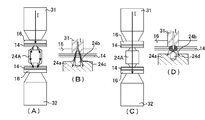
도 1의 (A)는 실시형태 1의 비수전해질 2차전지의 단면도이며, 도 1의 (B)는 도 1의 (A)의 IB-IB 선을 따른 단면도이며, 도 1의 (C)는 도 1의 (A)의 IC-IC 선을 따른 단면도이다.
도 2의 (A)는 실시형태 1의 양극용 연결도전부재의 평면도이며, 도 2의 (B)는 도 2의 (A)의 IIB-IIB 선을 따른 단면도이며, 도 2의 (C)는 양극용 연결도전부재의 정면도이며, 도 2의 (D)는 양극용 중간부재의 정면도이다.
도 3은 실시형태 1에 관한 용접상태를 나타내는 측면도이다.
도 4의 (A)는 돌기의 양극심체 노출부 접촉하고 있는 부분이 원환상(圓環狀)인 경우의 저항용접 전류가 흐르는 경로를 나타내는 도면이며, 도 4의 (B)는 도 4의 (A)의 발열이 강한 부분을 나타내는 도면이며, 도 4의 (C)는 돌기의 양극심체 노출부와 접촉하고 있는 부분이 원상(圓狀)인 경우의 저항용접 전류가 흐르는 경로를 나타내는 도면이며, 도 4의 (D)는 도 4의 (C)의 발열이 강한 부분을 나타내는 도면이다.
도 5의 (A) 내지 도 5의 (C)는 각각 실시형태 2 내지 4에 관한 양극용 연결도전부재의 형상을 나타내는 모식도이며, 도 5의 (D)는 실시형태 4의 양극용 중간부재를 2분할한 양극집전체 노출부에 장착한 상태의 모식측면도이다.
도 6의 (A)는 실시형태 5의 용접 후의 양극용 연결도전부재부분의 배치상태를 나타내는 측면도이며, 도 6의 (B)는 실시형태 6의 용접 후의 양극용 연결도전부재부분의 배치상태를 나타내는 측면도이다.
도 7(A) 내지 도 7의 (D)는 각각 실시형태 7 내지 10의 양극용 중간부재의 형상을 나타내는 정면도이며, 도 7의 (E)는 실시형태 10의 양극용 중간부재의 측면도이며, 도 7의 (F) 및 도 7의 (G)는 각각 실시형태 10의 양극용 중간부재와 조합시켜 사용하는 위치결정용 치구의 정면도 및 측면도이며, 도 7의 (H) 및 도 7의 (I)는 실시형태 10의 양극용 중간부재가 위치결정용 치구에 파지된 상태를 나타내는 평면도 및 측면도이며, 도 7의 (J) 및 도 7의 (K)는 실시형태 10의 변형예의 형상을 나타내는 양극용 중간부재의 평면도 및 위치결정용 치구에 파지된 상태를 나타내는 평면도이며, 도 7의 (L) 내지 도 7의 (N)은 실시형태 10에 관한 집진체 저항용접의 과정을 나타내는 측면도이다.
도 8의 (A)는 실시형태 11의 양극용 연결도전부재의 정면도이며, 도 8의 (B)는 도 8의 (A)의 종단면도이며, 도 8의 (C)는 환상 절연실링재의 평면도이며, 도 8의 (D)는 실시형태 11의 양극용 중간부재의 종단면도이다.
도 9의 (A)는 종래의 축전소자로서의 전기이중층 캐패시터의 단면도이며, 도 9의 (B)는 도 9의 (A)의 IXB-IXB 선에 따른 단면도이며, 도 9의 (C)는 도 9의 (A)의 IXC-IXC 선에 따른 단면도이다.
도 10은 도 9에 있어서의 전극의 심체 노출부와 집전부재와의 사이의 용접공정을 나타내는 도면이다.
도 11은 종래의 시리즈 스폿 용접법을 설명하는 도면이다.
도 12는 종래의 시리즈 스폿 용접한 극판심체 집결장치의 단면도이다.
도 13의 (A)는 다른 종래의 양극단자와 양극심체 노출부와의 용접전 상태를 나타내는 분해사시도이며, 도 13의 (B)는 용접 후의 사시도이다.FIG. 1A is a sectional view of the nonaqueous electrolyte secondary battery of Embodiment 1, FIG. 1B is a sectional view along the line IB-IB in FIG. 1A, and FIG. It is sectional drawing along the IC-IC line of FIG.
FIG. 2A is a plan view of the positive electrode connection conductive member of Embodiment 1, FIG. 2B is a cross-sectional view along the line IIB-IIB in FIG. 2A, and FIG. It is a front view of the connection conductive member for positive electrodes, and FIG. 2 (D) is a front view of the intermediate member for positive electrodes.
3 is a side view showing a welding state according to the first embodiment.
FIG. 4A is a diagram showing a path through which a resistance welding current flows when the portion of the protrusion contacting the exposed portion of the core of the projection is annular; FIG. 4B is a cross section of FIG. 4 is a diagram showing a portion where the heat generation of A) is strong, and FIG. 4C is a diagram showing a path through which a resistance welding current flows when the portion in contact with the anode core exposed portion of the projection is circular. FIG. 4D is a view showing a portion where heat generation is strong in FIG. 4C.
5A to 5C are schematic views showing the shapes of the connection conductive members for the positive electrode according to Embodiments 2 to 4, respectively, and FIG. 5D shows the intermediate member for the positive electrode according to the fourth embodiment. It is a schematic side view of the state attached to the positive electrode collector exposed part divided into two.
Fig. 6A is a side view showing the arrangement state of the positive electrode connection conductive member part after welding of Embodiment 5, and Fig. 6B shows the arrangement state of the positive electrode connection conductive member part after welding in Embodiment 6. It is a side view showing.
7A to 7D are front views each showing the shape of the positive electrode intermediate member of Embodiments 7 to 10, and FIG. 7E is a side view of the positive electrode intermediate member of
FIG. 8A is a front view of the positive electrode connection conductive member of
FIG. 9A is a sectional view of a conventional electric double layer capacitor as a power storage device, FIG. 9B is a sectional view taken along the line IXB-IXB in FIG. 9A, and FIG. It is sectional drawing along the IXC-IXC line of 9 (A).
It is a figure which shows the welding process between the core exposed part of an electrode, and a collector member in FIG.
It is a figure explaining the conventional series spot welding method.
12 is a cross-sectional view of a conventional pole plate core collecting device welded with a series spot.
FIG. 13A is an exploded perspective view showing a state before welding between another conventional anode terminal and an anode core exposed portion, and FIG. 13B is a perspective view after welding.
이하에 본 발명을 실시하기 위한 형태를 예시하고 상세하게 설명한다. 다만, 이하에 나타내는 각 실시형태는, 본 발명의 기술사상을 이해하기 위해서 예시하는 것으로, 본 발명을 이 실시형태에 특정하는 것을 의도하는 것이 아니고, 본 발명은 특허청구범위에 나타낸 기술사상을 일탈하지 않고 여러 가지의 변경을 행한 것에도 동등하게 적용할 수 있는 것이다. 또한 본 발명으로 사용할 수 있는 발전요소는, 양극극판과 음극극판을 세퍼레이터를 사이에 두고 적층 또는 권회함으로써, 일방의 단부에 복수매 적층된 양극심체 노출부가 형성되며, 타방의 단부에 복수매 적층된 음극심체 노출부가 형성된 편평형상의 것에 적용할 수 있지만, 이하에 있어서는, 편평형상의 권회전극체를 대표로 하여 설명한다.EMBODIMENT OF THE INVENTION Below, the form for implementing this invention is illustrated and it demonstrates in detail. However, each embodiment shown below is illustrated in order to understand the technical idea of this invention, and does not intend that this invention is specified to this embodiment, and this invention is a deviation from the technical idea shown by a claim. It can be applied equally to various changes made without doing so. In addition, the power generation element which can be used in the present invention is formed by stacking or winding the positive electrode plate and the negative electrode plate with the separator interposed therebetween, whereby a plurality of positive electrode core exposed portions are formed at one end portion, and the multiple sheets are laminated at the other end portion. Although it is applicable to the flat shape in which the negative electrode core exposed part was formed, it demonstrates below with the flat wound electrode body as a representative.
실시형태 1Embodiment 1
먼저, 실시형태 1의 각형 밀폐 2차전지의 예로서 각형 비수전해질 2차전지를 도 1 내지 도 3을 이용하여 설명한다. 또한, 도 1의 (A)는 실시형태 1의 비수전해질 2차전지의 단면도이며, 도 1의 (B)는 도 1의 (A)의 IB-IB 선을 따른 단면도이며, 도 1의 (C)는 도 1의 (A)의 IC-IC 선을 따른 단면도이다. 도 2의 (A)는 실시형태 1의 양극용 연결도전부재의 평면도이며, 도 2의 (B)는 도 2의 (A)의 IIB-IIB 선을 따른 단면도이며, 도 2의 (C)는 양극용 연결도전부재의 정면도이며, 도 2의 (D)는 양극용 중간부재의 정면도이다. 도 3은 실시형태 1에 관한 용접상태를 나타내는 측면도이다.First, the rectangular nonaqueous electrolyte secondary battery is described as an example of the rectangular sealed secondary battery of Embodiment 1 with reference to FIGS. 1A is a cross-sectional view of the nonaqueous electrolyte secondary battery of Embodiment 1, FIG. 1B is a cross-sectional view along the line IB-IB in FIG. 1A, and FIG. ) Is a cross-sectional view along the IC-IC line of FIG. 1A. FIG. 2A is a plan view of the positive electrode connection conductive member of Embodiment 1, FIG. 2B is a cross-sectional view along the line IIB-IIB in FIG. 2A, and FIG. It is a front view of the connection conductive member for positive electrodes, and FIG. 2 (D) is a front view of the intermediate member for positive electrodes. 3 is a side view showing a welding state according to the first embodiment.
이 비수전해질 2차전지(10)는, 양극극판과 음극극판이 세퍼레이터(모두 도시 생략)를 사이에 두고 권회된 편평형상의 권회전극체(11)를 가지고 있다. 양극극판은, 알루미늄박으로 이루어진 양극심체의 양면에 양극 활물질(活物質) 합제(合劑)를 도포하고, 건조 및 압연한 후 알루미늄박이 띠형상으로 노출하도록 슬릿함으로써 제작되어 있다. 또한, 음극극판은 동박으로 이루어지는 음극심체의 양면에 음극 활물질 합제를 도포하고, 건조 및 압연한 후, 동박이 띠형상으로 노출하도록 슬릿함으로써 제작되어 있다.This nonaqueous electrolyte
그리고, 위에서 설명한 바와 같이 하여 얻어진 양극극판 및 음극극판을, 양극극판의 알루미늄박 노출부와 음극극판의 동박 노출부가 각각 대향하는 전극의 활물질층과 겹치지 않게 어긋나게 하고, 폴리에틸렌제 다공질 세퍼레이터를 사이에 두고 권회함으로써, 권회축방향의 일방의 단부에는 복수개 겹친 양극 심체 노출부(14)를 구비하며, 타방의 단부에는 복수매 겹친 음극 심체 노출부(15)를 구비한 편평형상의 권회전극체(11)가 제작되어 있다.The positive electrode plate and the negative electrode plate obtained as described above are shifted so that the aluminum foil exposed portion of the positive electrode plate and the copper foil exposed portion of the negative electrode plate do not overlap with the active material layer of the opposite electrode, respectively, with a polyethylene porous separator interposed therebetween. By winding, the flat
복수매의 양극심체 노출부(14)는 적층되며 양극용 집전부재(16)를 통해서 양극단자(17)에 접속되고, 마찬가지로 복수매의 음극심체 노출부(15)는 적층되며 음극용 집전부재(18)를 통해서 음극단자(19)에 접속되어 있다. 또한, 양극단자(17), 음극단자(19)는 각각 절연부재(20, 21)를 통해서 봉구판(封口板)(13)에 고정되어 있다. 이 실시형태 1의 각형의 비수전해질 2차전지(10)는, 위에서 설명한 바와 같이 하여 제작된 편평형상의 권회전극체(11)의 봉구판(13)측을 제외하는 주위에 절연시트(도시 생략)를 개재시켜 각형의 전지 외장캔(12) 내에 삽입한 후, 봉구판(13)을 전지 외장캔(12)의 개구부에 레이저 용접하고, 그 후, 전해액 주액공(注液孔)(22)으로부터 비수 전해액을 주액하고, 이 전해액 주액공(22)을 밀폐함으로써 제작되어 있다.The plurality of positive electrode core exposed
편평형상의 권회전극체(11)는, 도 1의 (B) 및 도 1의 (C)에 나타내는 바와 같이, 양극극판측에서는, 적층된 복수매의 양극심체 노출부(14)가 2분할되고 그 사이에 양극용 연결도전부재(24A)를 복수개, 여기에서는 2개 유지한 수지재료로 이루어지는 양극용 중간부재(24)가 끼워져 있으며, 마찬가지로 음극극판측에서는, 적층된 복수매의 음극심체 노출부(15)가 2분할되고 그 사이에 음극용 연결도전부재 (25A)를 2개 유지한 수지재료로 이루어지는 음극용 중간부재(25)가 끼워져 있다. 또한, 양극용 연결도전부재(24A)의 양측에 위치하는 양극심체 노출부(14)의 최외측의 양측의 표면에는 각각 양극용 집전부재(16)가 배치되어 있으며, 음극용 연결도전부재(25A)의 양측에 위치하는 음극심체 노출부(15)의 최외측의 양측 표면에는 각각 음극용 집전부재(18)가 배치되어 있다.As for the flat
또한, 실시형태 1에 있어서는, 양극용 중간부재(24) 및 음극용 중간부재(25)는 각각 양극용 연결도전부재(24A) 내지 음극용 연결도전부재(25A)를 2개씩 유지 시킨 것을 이용한 예를 나타냈지만, 양극용 연결도전부재(24A) 내지 음극용 연결도전부재(25A)의 수는 요구되는 전지의 출력 등에 따라 적절하게 3개 이상 마련해도 된다. 또한, 양극용 연결도전부재(24A)는 양극심체와 동일한 재료인 알루미늄제이며, 음극용 연결도전부재(25A)는 음극심체와 동일한 재료인 동제이지만, 양극용 연결도전부재(24A) 및 음극용 연결도전부재(25A)의 형상은 동일하여도 되고 달라도 된다.In Embodiment 1, the positive electrode
이들 양극용 집전부재(16)와 양극심체 노출부(14)와의 사이 및 양극심체 노출부(14)와 양극용 연결도전부재(24A)와의 사이(각각 4개소, 도 1의 (B) 참조)는 모두 저항용접되어 있으며, 또한, 음극용 집전부재(18)와 음극심체 노출부(15)와의 사이 및 음극심체 노출부(15)와 음극용 연결도전부재(25A)와의 사이(각각 4개소)도 모두 저항용접에 의해서 접속되어 있다.Between the positive electrode
이하, 편평형상의 권회전극체(11)의 구체적 제조방법 및 양극심체 노출부(14), 양극용 집전부재(16), 양극용 연결도전부재(24A)를 가지는 양극용 중간부재(24)를 이용한 저항용접방법 및 음극심체 노출부(15), 음극용 집전부재(18), 음극용 연결도전부재(25A)를 가지는 음극용 중간부재(25)를 이용한 저항용접방법을 도 2 및 도 3을 이용하여 상세하게 설명한다. 그렇지만, 실시형태 1에 있어서는, 양극용 연결도전부재(24A)와 양극용 중간부재(24)의 형상 및 음극용 연결도전부재(25A)와 음극용중 중간부재(25)의 형상은 실질적으로 동일하게 할 수 있으며, 게다가 각각의 저항용접방법도 실질적으로 동일하므로, 이하에서는 양극극판측의 것을 대표로 하여 설명하는 것으로 한다.Hereinafter, a method for manufacturing a flat
먼저, 양극극판 및 음극극판을 양극극판의 알루미늄박 노출부와 음극극판의 동박 노출부가 각각 대향하는 전극의 활물질층과 겹치지 않게 어긋나게 하고, 폴리에틸렌제 다공질 세퍼레이터를 사이에 두고 권회하여 얻어진 편평형상의 권회전극체(11)의 양극심체 노출부(14)를, 권회중앙부분으로부터 양측으로 2분할하고, 전극체 두께의 1/4을 중심으로 하여 양극심체 노출부(14)를 집결시켰다. 그리고, 양극심체 노출부(14)의 최외주측의 양면에 양극용 집전부재(16), 내주측에 양극용 연결도전부재(24A)를 가지는 양극용 중간부재(24)를, 양극용 연결도전부재(24A)의 양측의 원뿔대 형상의 돌기(24b)가 각각 양극심체 노출부(14)와 맞닿도록, 2분할된 양극심체 노출부(14)의 사이에 삽입했다. 여기서, 집결시킨 알루미늄박의 두께는 한쪽 측이 약 660 ㎛이며, 총 적층수는 88매(한쪽 측이 44매)이다. 또한, 양극용 집전부재(16)는 두께 O.8mm의 알루미늄판을 펀칭하며, 굽힘가공 등에 의해 제작했다. 또한, 이 양극용 집전부재(16)는 알루미늄판으로부터 주조 등에 의해 제작하여도 된다.First, the flat winding obtained by winding the positive electrode plate and the negative electrode plate so that the aluminum foil exposed portion of the positive electrode plate and the copper foil exposed portion of the negative electrode plate does not overlap with the active material layer of the opposite electrode, and is wound with a porous porous polyethylene separator interposed therebetween. The positive electrode core exposed
여기서, 실시형태 1의 양극용 중간부재(24)에 유지된 양극용 연결도전부재(24A)의 형상을 도 2를 이용하여 설명한다. 이 양극용 연결도전부재(24A)는, 원주상의 본체(24a)의 대향하는 2개의 면(24e)의 각각에 예를 들면 원뿔대 형상의 돌기(24b)가 형성되어 있다. 그리고, 이 원뿔대형상의 돌기(24b)의 중앙부에는, 선단측으로부터 원주상의 본체(24a)의 내부까지 개구(24c)가 형성되어 있으며 또한, 원주상의 본체(24a)의 대향하는 2개의 면(24e)과 측면과의 사이에 각부(24f)가 형성되어 있다.Here, the shape of the positive electrode connection
이 원뿔대 형상의 돌기(24b)의 높이 H는, 저항용접부재에 일반적으로 형성되어 있는 돌기(프로젝션)와 동일한 정도, 즉, 수 mm정도이면 된다. 또한, 개구(24c)의 깊이 D는, 여기에서는 원뿔대 형상의 돌기(24b)의 높이 H 보다도 크게 되며, 개구(24c)는 돌기(24b)가 마련된 원주상의 본체(24a)의 면(24e)으로부터 돌기(24b)의 높이 H의 깊이보다도 얕은 위치까지 형성되어 있는 것(개구(24c)의 깊이 D는 2H 보다 작음)이 바람직하며, 돌기(24b)가 마련된 원주상의 본체(24a)의 표면으로부터 돌기(24b)의 높이 H의 1/2의 깊이보다 얕은 위치까지 형성되어 있는 것(개구(24c)의 깊이 D는 3/2H 보다 작음)이 바람직하다.The height H of the truncated
또한, 원주상의 본체(24e)의 직경 및 길이는 편평형상의 권회전극체(11)나 전지외장캔(12)(도 1 참조)에 의해서도 변화하지만, 3 mm ~ 수 10 mm 정도라면 된다. 또한 여기서는 양극용 연결도전부재(24A)의 본체(24a)의 형상은 원주상인 것으로 하여 설명했지만, 각주상, 타원주상 등, 금속제의 블록형상인 것이면 임의의 형상인 것을 사용할 수 있다. 또한, 양극용 연결도전부재(24A)의 형성 재료로서는, 동, 동합금, 알루미늄, 알루미늄합금, 텅스텐, 몰리브덴 등으로 이루어지는 것을 사용할 수 있으며, 더욱이, 이들 금속으로 이루어지는 것 가운데, 돌기(24b)에 니켈도금을 행한 것, 돌기(24b)와 그 기초 부근까지를 텅스텐 또는 몰리브덴 등의 발열을 촉진하는 금속재료로 변경하고, 동, 동합금, 알루미늄 또는 알루미늄합금으로 이루어지는 양극용 연결도전부재(24A)의 본체(24a)에 브레이징(brazing) 등에 의해서 접합한 것 등도 사용할 수 있다.The diameter and length of the cylindrical
또한, 실시형태 1의 양극용 연결도전부재(24A)는 복수개, 예를 들면 2개가 수지재료로 이루어지는 양극용 중간부재(24)에 의해서 일체로 유지되고 있다. 이 경우, 각각의 양극용 연결도전부재(24A)는 서로 평행하게 되도록 유지되고 있다. 이 양극용 중간부재(24)의 형상은 각주상, 원주상 등 임의의 형상을 취할 수 있지만, 2분할한 양극집전체 노출부(14) 내에서 안정적으로 위치결정하여 고정되도록 하기 위해서는, 가로로 긴(橫長) 각주상으로 하는 것이 바람직하다. 다만, 양극용 중간부재(24)의 각부는, 연질의 양극집전체 노출부(14)와 접촉하여도 양극심체 노출부(14)에 상처가 나거나 변형하거나 하지 않게 하기 위해, 모따기하는 것이 바람직하다. 이 모따기 부분은, 적어도 2분할된 양극집전체 노출부(14) 내에 삽입되는 부분이면 좋다.In addition, the positive electrode connection
그리고, 각주상의 양극용 중간부재(24)의 길이 W는, 각형 비수전해질 2차전지의 사이즈에 의해서도 변화하는데, 20 mm ~ 수십 mm로 할 수 있으며, 그 폭 h는 양극용 연결도전부재(24A)의 높이와 동일한 정도가 되도록 하면 되지만, 적어도 용접부가 되는 양극용 연결도전부재(24A)의 양단이 노출하고 있으면 좋다. 또한, 양극용 연결도전부재(24A)의 양단은, 양극용 중간부재(24)의 표면으로부터 돌출하고 있는 것이 바람직하지만, 반드시 돌출하고 있지 않아도 된다. 이와 같은 구성이면, 양극용 연결도전부재(24A)는 양극용 중간부재(24)에 유지되어 있으며, 게다가, 양극용 중간부재(24)는 2분할된 양극심체 노출부(14)의 사이에 안정적으로 위치결정된 상태로 배치된다.The length W of the
다음으로, 도 3에 나타낸 것과 같이, 상하로 배치된 한 쌍의 저항용접용 전극봉(31 및 32) 사이에 양극용 집전부재(16) 및 양극용 연결도전부재(24A)를 유지 한 양극용 중간부재(24)가 배치된 편평형상의 권회전극체(11)를 배치하고, 한 쌍의 저항용접용 전극봉(31 및 32)을 각각 양극심체 노출부(14)의 최외주측의 양면에 배치된 양극용 집전부재(16)에 맞닿게 한다. 그리고, 한 쌍의 저항용접용 전극봉(31및 32) 사이에 적당한 압력을 인가하여, 미리 정한 일정한 조건에서 저항용접을 실시한다.Next, as shown in FIG. 3, the positive electrode middle holding the positive electrode
이 저항용접에 있어서는, 양극용 중간부재(24)는 2분할된 양극심체 노출부(14)의 사이에 안정적으로 위치결정된 상태로 배치되어 있으므로, 한 쌍의 저항용접용 전극봉(31 및 32)을 1조만 이용하여 복수개의 양극용 연결도전부재(24A) 부분을 1개씩 저항용접하여도 되며, 또는, 한 쌍의 저항용접용 전극봉(31 및 32)을 복수조 이용하여 복수개의 양극용 연결도전부재(24A) 부분을 2개 이상 모아 저항용접하여도 좋다. 이 실시형태 1의 양극용 중간부재(24)를 이용하면, 연결도전부재 (24A)와 전극봉(31 및 32) 사이의 치수 정밀도가 향상되고 있으므로, 정확하게 그리고 안정된 상태에서 저항용접하는 것이 가능해져, 용접강도가 편차지게 되는 것이 억제된다.In this resistance welding, since the
또한, 실시형태 1의 양극용 연결도전부재(24A)는, 돌기(24b)에 개구(24c)가 형성되어 있기 때문에, 돌기(24b)의 선단부에 전류가 집중하기 쉽고, 또한 돌기(24b)의 선단이 양극심체 노출부(14)로 파고들기 쉽게 되기 때문에, 개구(24c)가 형성되어 있지 않은 경우보다 용접성이 향상된다. 그리고, 돌기(24b)의 선단부가 반 찌그러진 상태가 되어, 돌기(24b)가 양극심체 노출부(14)와 접촉하고 있는 부분이 원환상에서 원상으로 변화하도록 압력을 가하여 저항용접을 행하면, 보다 안정적으로 용접을 행할 수 있다.In addition, since the
따라서, 양극용 연결도전부재(24A)의 돌기(24b)의 형상은, 예를 들어 도 4의 (D)에 나타내는 바와 같이, 돌기(24b)의 선단부가 반(半)찌그러진 상태가 되며, 돌기(24b)가 양극심체 노출부(14)와 접촉하고 있는 부분이 원환상에서 원상으로 변화하고 있도록 하는 것이 바람직하다. 이 경우, 돌기(24b)의 내부에는 공동(24d)이 형성되어 있다. 이것은, 돌기(24b)의 양극심체 노출부(14)와의 접촉부를 원상으로 함으로써 양극용 연결도전부재(24A) 중심으로부터의 발열을 촉진하여, 한층 더 안정된 용접이 가능해진다.Therefore, the shape of the
또한, 돌기(24b)가 양극심체 노출부(14)와 접촉하고 있는 부분이, 반 찌그러진 상태가 되는지 원환상으로 되는지는, 주로 용접시의 가압력에 의존하는 것을 알 수 있고, 용접 가압력이 약한 경우는 돌기 선단이 환상이 되며, 용접 가압력이 강한 경우는 돌기 선단이 반 찌그러진 형상이 되는 경향이 있다. 또한 그 외에는 돌기(24b)의 높이가 높고 또한 개구(24c)의 깊이가 깊을수록 반 찌그러진 상태로 되기 쉬우며, 개구의 깊이가 얕은 경우는 돌기(24b)의 선단이 환상인 채로 심체 노출부로 파고드는 상태가 되기 쉬운 것이라고 생각된다.In addition, it can be seen that the part where the
또한 이 저항용접시에는 한 쌍의 저항용접용 전극봉(31 및 32)과 양극용 연결도전부재(24A)의 중심축이 일치하고 있는 것이 바람직하며, 양극용 연결도전부재(24A)는 가압 등에 의해 위치가 어긋나지 않도록 유지되어 있는 바람직하다. 또한 저항용접기로서는 주지의 트랜지스터 등을 이용한 반도체식 용접전원을 사용할 수 있다.In this resistance welding, it is preferable that the central axes of the pair of
여기서, 상기의 돌기(24b)가 양극심체 노출부(14)와 접촉하고 있는 부분이 원환상인 경우와 원상인 경우에, 발열상태에 차이가 발생하는 이유에 대해서, 도 4를 이용하여 설명한다. 또한, 도 4의 (A)는 돌기(24b)가 양극심체 노출부(14)와 접촉하고 있는 부분이 원환상인 경우의 저항용접 전류가 흐르는 경로를 나타내는 도면이며, 도 4의 (B)는 도 4의 (A)의 발열이 강한 부분을 나타내는 도면이며, 도 4의 (C)는 돌기(24b)가 양극심체 노출부(14)와 접촉하고 있는 부분이 원상인 경우의 저항용접 전류가 흐르는 경로를 나타내는 도면이며, 도 4의(D)는 도 4의 (C)의 발열이 강한 부분을 나타내는 도면이다.Here, the reason why the difference in heat generation occurs in the case where the portion where the
전류는 가장 저항값이 적은 개소를 흐르기 때문에, 저항용접용 전극봉(31 및 32)의 내부에서는 그 중심이 전류가 흐르는 부분이 된다. 돌기(24b)가 양극심체 노출부(14)와 접촉하고 있는 부분이 원환상인 경우, 도 4의 (A)에 나타내는 것과 같이, 용접전류 I는, 예를 들면 상측의 저항용접용 전극봉(31)으로부터 상측의 양극용 집전부재(16) 및 양극심체 노출부(14)를 거쳐, 양극용 연결도전부재(24A)의 상측의 돌기(24b)의 원환상의 선단부로부터 원환상으로 분류(分流)되어 양극용 연결도전부재(24A)의 본체(24a) 내로 흐르며, 또한 양극용 연결도전부재(24A)의 하측의 돌기(24b)의 원환상의 선단부를 지나 전류가 집중되며, 하측의 양극심체 노출부(14) 및 양극용 집전부재(16)를 거쳐, 하측의 저항용접용 전극봉(32)으로 흐른다. 이 때문에, 돌기(24b)가 양극심체 노출부(14)와 접촉하고 있는 부분이 원환상인 경우, 돌기(24b)의 중심에는 전류가 흐르지 않기 때문에, 도 4의 (B)에 나타낸 것과 같이, 원환상으로 용접의 기점이 발생함으로써, 용접의 기점이 다수가 된다.Since the current flows through the smallest resistance value, the center of the
그것에 대해서, 돌기(24b)가 양극심체 노출부(14)와 접촉하고 있는 부분이 반 찌그러진 상태가 되어 원상으로 되어 있는 경우, 돌기(24b)의 내부에는 공동(24d)이 형성되어 있기 때문에, 도 4의 (C)에 나타내는 바와 같이, 용접전류 I는, 예를 들면 상측의 저항용접용 전극봉(31)으로부터 상측의 양극용 집전부재(16) 및 양극심체 노출부(14)를 거쳐, 양극용 연결도전부재(24A)의 상측의 돌기(24b)의 원상의 선단부의 중심으로부터 원환상으로 분류되어 양극용 연결도전부재(24A)의 본체(24a) 내로 흐르며, 또한 양극용 연결도전부재(24A)의 하측의 돌기(24b)의 원상의 선단부의 중심을 지나 전류가 집중되어 하측의 양극심체 노출부(14) 및 양극용 집전부재(16)를 거쳐, 하측의 저항용접용 전극봉(32)으로 흐른다.On the other hand, when the part in which the
이 예에서는, 용접전류 I는, 돌기(24b) 부분에서 공동(24d)부분을 피해서 원환상으로 전류가 분류되지만, 원상의 선단부의 중심 내부에 공동(24d)이 존재하고 있기 때문에, 금속의 용융에 수반하는 흡열이 적게 되므로, 돌기(24b)의 원상의 선단부의 중심 부근이 가장 발열하기 쉬워진다. 이 때문에, 돌기(24b)가 양극심체 노출부(14)와 접촉하고 있는 부분이 원상인 경우, 돌기(24b)의 원상의 선단부의 중심으로 전류가 집중하기 때문에, 용접전류 I에 의해서 강하게 발열하는 부분의 형상은, 도 4의 (D)에 나타낸 것과 같이 구상(球狀)이 되므로, 보다 안정된 용접 상태가 되며 게다가, 용접 강도도 강해진다.In this example, the welding current I flows in an annular shape, avoiding the
또한, 상기 실시형태 1에서는, 양극용 연결도전부재(24A)로서 주상(柱狀)의 본체(24a)를 가지며, 돌기(24b)로서 개구(24c)가 형성되어 있는 원뿔대 형상인 것을 이용한 예를 나타냈다. 그렇지만, 본 발명에 있어서는, 돌기(24b)는 개구가 형성되어 있지 않은 것이라도, 각뿔대 형상인 것, 즉, 삼각뿔대 형상인 것이나 사각뿔대 형상인 것이나 더욱이 다각뿔대 형인 것도 사용할 수 있다. 또한 반구(半球) 형상인 것이어도 된다.In the first embodiment, an example is used in which a positive pole connection
돌기(24b)에 개구가 형성되어 있지 않은 경우, 돌기(24b)의 작용은 종래의 저항용접시의 프로젝션과 동일하게 되지만, 이 경우에도 양극용 집전부재(16), 적층된 복수매의 양극심체 노출부(14) 및 양극용 연결도전부재(24A)와의 사이의 저항용접을 행할 수 있다. 이 경우, 돌기(24b)에 형성하는 개구(24c)의 깊이가 얕아지면, 저항용접시에 발생하는 작용효과는 서서히 돌기(24b)에 개구를 형성하지 않는 상태에 가까워져 간다.When no opening is formed in the
또한, 양극용 연결도전부재(24A)로서 원주상의 본체(24a)를 가지는 것을 사용한 예를 나타냈지만, 양극용 연결도전부재(24A)의 본체(24a)로서는 각주상, 타원주상 등의 금속제의 블록형상인 것이면 좋고, 더욱이 개구(24c)(도 2 참조)가 본체(24a)를 관통하고 있는 것도 사용할 수 있다. 특히, 개구(24c)가 본체 (24a)를 관통하고 있는 경우는, 양극용 연결도전부재(24A)의 본체(24a)는 통형상의 것이 되지만, 이 경우는, 본체(24a)의 양단부를 성형하여 또는 그대로 돌기로서 겸용시킬 수 있다. 이와 같이 양극용 연결도전부재(24A)의 본체(24a)를 통형상으로 했을 경우, 전기저항을 작게 하기 위해서는 통형상 부분의 두께를 어느 정도 두껍게 하는 것이 좋다.In addition, although the example which used the circumferential
또한, 상기 실시형태 1에서는, 적층된 복수매의 양극심체 노출부(14)를 2분할하고, 양극용 집전부재(16) 및 양극용 연결도전부재(24A)를 이용하여 저항용접 하는 경우에 대해서 설명했지만, 양극용 연결도전부재(24A)를 양극용 집전부재에 겸용하여 이 양극용 연결도전부재(24A)를 양극단자(17)에 접속해도 된다. 이 경우, 상기 실시형태 1에서 사용되고 있는 양극용 집전부재에 대신하여 양극용 연결도전부재(24A)와 동일한 재료로 형성된 박판재로 이루어지는 용접받이부재를 이용하면 좋다. In the first embodiment, a plurality of stacked positive electrode core exposed
실시형태 2 내지 4Embodiments 2 to 4
실시형태 1의 양극용 중간부재(24)에 유지되는 양극용 연결도전부재(24A)로서는 도 2에 나타낸 것과 같이 원주상의 본체(24a)의 대향하는 2개의 면(24e) 각각에 예를 들면 원뿔대 형상의 돌기(24b)가 형성되어 있는 것을 나타냈다. 이와 같이 본체(24a)가 원주상이면, 원주상의 본체(24a)의 대향하는 2개의 면(24e)과 측면과의 사이에 각부(24f)가 형성된다. 이 때문에, 도 3에 나타내는 바와 같이, 양극용 연결도전부재(24A)를 유지한 양극용 중간부재(24)를 적층된 양극심체 노출부(14)를 2분할하고 그 내측에 배치하며, 양극용 연결도전부재(24A)의 양측의 원뿔대 형상의 돌기(24b)가 각각 적층된 양극심체 노출부(14)와 맞닿도록 할 때, 각부(24f)가 양극용 중간부재(24)의 표면으로부터 노출하고 있으면, 이 노출하고 있는 각부(24f)가 적층된 양극심체 노출부(14)와 접촉하기 쉽기 때문에, 양극심체 노출부(14)가 변형되기 쉬워진다.As the positive electrode connection
그래서, 실시형태 2의 양극용 연결도전부재(24B)로서는, 실시형태 1의 원주상의 본체(24a)의 대향하는 2개의 면(24e)과 측면과의 사이의 각부(24f)에 모따기 되어 있는 면(24g)을 형성하였다. 이 실시형태 2의 양극용 연결도전부재(24B)를 도 5의 (A)를 이용하여 설명한다. 또한, 도 5의 (A)는 실시형태 2의 양극용 연결도전부재(24B)의 정면도이다.Therefore, as the positive electrode connection
이와 같이 모따기 되어 있는 면(24g)을 형성한 실시형태 2의 양극용 연결도전부재(24B)에 의하면, 적층된 양극심체 노출부(14)를 2분할하고 그 내측에 양극용 중간부재(24)를 양극용 연결도전부재(24B)의 양측의 원뿔대 형상의 돌기(24b)가 각각 양극심체 노출부(14)와 맞닿도록 배치할 때, 비록 모따기되어 있는 면(24g)이 양극용 중간부재(24)의 표면보다 돌출하고 있어도, 적층된 양극심체 노출부(14)에 손상을 주는 것이 적어지며, 용이하게 적층된 양극심체 노출부(14)의 용접위치에까지 삽입시킬 수 있게 되어, 용접성이 향상된다.According to the positive electrode connection
또한, 실시형태 2의 양극용 연결도전부재(24B)에 있어서의 모따기되어 있는 면(24g)은, 곡면 및 평면의 어느 쪽도 채용할 수 있지만, 모따기되어 있는 면(24g)을 평면형상으로 하면, 모따기되어 있는 면(24g)과 돌기(24b)가 형성된 면과의 사이가 적층된 양극심체 노출부(14)에 대해서 반드시 둔각이 되므로, 양극용 연결도전부재(24B)가 적층된 양극심체 노출부(14)와 접촉시킬 때에 양극심체 노출부(14)와 돌기(24b)가 접촉하기 쉬워지므로 보다 용접성이 향상된다.In addition, although the chamfered
또한, 실시형태 3의 양극용 연결도전부재(24C)에 대해서는, 도 5의 (B)에 나타낸 것과 같이, 양극용 연결도전부재(24C)와 같이, 모따기되어 있는 면(24g)이 돌기(24b)의 형성부분에까지 연장되어 있으며, 실시형태 2의 양극용 연결도전부재(24 B)의 본체(24a)에 있어서의 각각 서로 평행한 2개의 평면으로 이루어지는 면(24e)이 존재하지 않는 형상을 도시하였다. 이 실시형태 3의 양극용 연결도전부재(24C)도 일응 양호한 저항용접 효과를 발휘한다.In addition, about 24C of positive electrode connection conductive members of Embodiment 3, as shown in FIG.5 (B), the
그렇지만, 실시형태 2의 양극용 연결도전부재(24B)와 같이, 돌기(24b)가 마련되어 있는 2개의 면(24e)이 각각 노출하고 있는 상태, 즉, 양극용 연결도전부재(24B)의 본체(24a)에 각각 서로 평행한 2개의 평면으로 이루어지는 면(24e)이 형성되어 있는 상태로 하면, 저항용접시에 저항용접용 전극으로 가압되었을 때에 양극용 연결도전부재(24B)가 변형하기 어렵게 되고, 또한, 저항용접시에 용융 변형한 돌기(24b)의 일부 혹은 용융한 양극심체 노출부(14)의 일부가 이 면(24e)에 머물게 되어 양극용 연결도전부재(24B)의 측면방향으로 흘러나오는 것이 억제되며, 게다가, 면(24e)이 양극심체 노출부(14)와 접하는 면으로 되는 것에 의해 양극용 연결도전부재(24B)의 위치가 안정화되어 보다 신뢰성이 높은 저항용접부를 얻을 수 있게 되기 때문에 보다 바람직하다.However, like the
또한, 실시형태 4의 양극용 연결도전부재(24D)는, 실시형태 2의 양극용 도전 부재(24B)에 있어서, 돌기(24b)의 중앙부에, 돌기(24b)의 높이 H보다 얕은 깊이 D의 개구(24c)를 마련한 것이다.Further, the positive electrode connection
또한, 실시형태 2 내지 4의 양극용 연결도전부재(24B 내지 24D)와 같이, 모따기되어 있는 면(24g)을 형성하면, 양극용 중간부재(24)를 2분할된 양극심체 노출부(14) 사이에 삽입하기 쉽게 되는 것을 나타내기 위해, 실시형태 4의 양극용 연결도전부재(24D)를 이용했을 경우에 대해서, 저항용접을 실시했을 때의 모식측면도를 도 5의 (D)에 나타낸다. 도 5의 (D)의 기재에 따르면, 양극용 중간부재(24)의 표면으로부터 양극용 연결도전부재(24D)가 돌출하고 있어도, 기하학적으로 양극심체 노출부(14)가 변형하기 어려운 것을 이해할 수 있다. 또한, 도 5의 (D)에는, 양극용 중간부재(24)가 양극심체 노출부(14) 사이에 삽입되는 측의 각부가 모따기된 예도 나타나 있다. 이 도 5에 나타낸 양극용 중간부재(24)의 형상으로 해도, 양극용 중간부재(24)를 2분할된 양극심체 노출부(14) 사이에 삽입하는 경우에도, 기하학적으로 양극심체 노출부(14)가 변형하기 어려운 것을 이해할 수 있을 것이다.Also, like the connection
실시형태 5 및 6Embodiments 5 and 6
또한, 상기 실시형 1 및 4에서는, 편평형상의 권회전극체(11)의 양극심체 노출부(14)를 권회중앙부분으로부터 양측으로 2분할하여 집결시키고, 양극심체 노출부(14)의 최외주측의 양면에 양극용 집전부재(16)를 맞닿게 하여, 양극용 연결도전부재(24A 내지 24D)를 가지는 양극용 중간부재(24)를 2분할된 양극심체 노출부(14) 사이에 삽입하고, 양극용 집전부재(16)의 양면에 한 쌍의 저항용접용 전극(31, 32)을 맞닿게 하여 저항용접을 한 예(도 3 참조)를 나타냈다. 그렇지만 본 발명에 있어서는 2분할된 양극심체 노출부(14)의 최외주측의 양면에 양극단자(17)에 접속된 양극용 집전부재(16)를 맞닿게 하는 것은 반드시 필요한 조건은 아니며, 적어도 2분할된 양극심체 노출부(14)의 일방의 면에 양극용 집전부재(16)를 맞닿게 하여 저항용접하면 된다.Further, in the first and fourth embodiments, the anode core exposed
이와 같은 적어도 2분할된 양극심체 노출부(14)의 일방의 면에 양극단자(17)에 접속된 양극용 집전부재(16)를 맞닿게 한 실시형태 5 및 6의 용접 후의 양극용 연결도전부재(24) 부분의 배치상태를, 도 6을 이용하여 설명한다. 또한 도 6의 (A)는 실시형태 5의 용접 후의 양극용 연결도전부재(24) 부분의 배치상태를 나타내는 측면도이며, 도 6의 (B)는 실시형태 6의 용접 후의 양극용 연결도전부재(24) 부분의 배치상태를 나타내는 측면도이다. 또한, 실시형태 5 및 6에서는, 양극용 중간부재(24)로서 실시형태 1에서 사용한 것과 동일한 양극용 연결도전부재(24A)를 구비하고 있는 것을 이용하여 설명한다.The positive electrode connection conductive member after welding of Embodiments 5 and 6, wherein the positive electrode
실시형태 5에서는, 도 6의 (A)에 나타내는 바와 같이, 2분할된 양극심체 노출부(14)의 최외측의 일방의 면에는 양극단자(17)에 접속된 양극용 집전부재(16)가 맞닿게 하도록 배치함과 아울러, 2분할된 양극심체 노출부(14)의 최외측의 타방의 면에는 집전받이부재(16a)가 맞닿게 하도록 배치하고, 양극용 집전부재(16)와 집전받이부재(16a)와의 사이에 한 쌍의 저항용접용 전극을 맞닿게 하여 저항용접을 행한 것이다. 이 경우, 이 실시형태 5에서는, 집전받이부재(16a)는, 직접 양극단자(17)와는 전기적으로 접속되어 있지 않으며, 저항용접시에 한 쌍의 저항용접용 전극의 일방측을 받아들이는 역할을 한다. 본 발명에 있어서의 「집전부재」는 이와 같은 「집전받이부재」도 포함하는 의미로 이용되고 있다. 저항용접은, 집전부재를 2분할된 심체 노출부의 최외측의 양쪽 면에 배치한 편이, 물리적으로 안정된 상태에서 행할 수 있다.In Embodiment 5, as shown to FIG. 6 (A), the positive electrode
또한, 실시형태 6에서는, 도 6의 (B)에 나타내는 바와 같이, 2분할된 양극심체 노출부(14)의 최외측의 일방의 면에는 양극용 집전부재(16)가 맞닿게 하도록 배치함과 아울러, 2분할된 양극심체 노출부(14)의 최외측의 타방의 면에는, 아무것도 마련하지 않으며, 양극용 집전부재(16)와 2분할된 양극심체 노출부(14)의 타방측과의 사이에 한 쌍의 저항용접용 전극을 맞닿게 하여 저항용접을 행한 것이다. 즉, 이 실시형태 6에서는, 저항용접시에 한 쌍의 저항용접용 전극의 일방측을 2분할된 양극심체 노출부(14)의 최외측의 타방의 면에 직접 접촉시켜 저항용접을 행하고 있다. 이 실시형태 6과 같은 구성에서도 일응 양호한 저항용접을 행할 수 있지만, 저항용접용 전극과 양극심체 노출부(14)의 최외측의 타방의 면과의 사이에 융착이 발생할 가능성이 있으므로, 실시형태 1 내지 5와 같이, 양극심체 노출부(14)의 최외측의 타방의 면에는, 양극용 집전부재(16) 내지 집전받이부재(16a)를 배치하는 것이 바람직하다.In addition, in Embodiment 6, as shown to FIG. 6 (B), it arrange | positions so that the anode
실시형태 7 내지 10Embodiments 7 to 10
상기 실시형태 1에서는, 합성수지제의 양극용 중간부재(24)로서 직방체 형상인 것을 이용한 예를 나타냈지만, 본 발명에서는 연결도전부재(24A)를 안정하게 유지할 수 있으면 실시할 수 있기 때문에, 합성수지제의 양극용 중간부재(24)의 형상으로서는 직방체에 한정되는 것은 아니다. 예를 들면, 도 7의 (A)에 나타낸 실시형태 7의 양극용 중간부재(241)와 같이, 양극용 연결도전부재(24A) 사이에 노치부분(24x)을 형성하거나, 도 7의 (B)에 나타낸 것과 같이 실시형태 8의 양극용 중간부재(242)와 같이 길이방향으로 관통공(24y)을 형성하거나, 도 7의 (C)에 나타낸 실시형태 9의 양극용 중간부재(243)와 같이, 양극용 연결도전부재(24A) 사이에 개구(24z)를 형성하거나 해도 된다. 이와 같은 구성을 채용하면, 이들 노치부분(24x), 관통공(24y), 개구(24z) 등이 가스빼기 통로로서 작용하기 때문에, 전지에 이상이 생겼을 때, 전극체 내부에 발생한 가스를 용이하게 전극체의 외부로 배출할 수 있으며, 각형 밀폐 전지에 보통으로 구비되어 있는 감압식 전류차단기구나 가스배출밸브 등이 안정적으로 동작하므로, 안전성을 확보할 수 있으며, 신뢰성의 높은 각형 밀폐 2차전지를 제조할 수 있게 된다.In the first embodiment, an example in which a rectangular parallelepiped shape is used as the positive electrode
또한, 도 7의 (D), 도 7의 (E)에 나타낸 실시형태 10의 양극용 중간부재(244)와 같이, 노치부분(24x')을 양극용 중간부재(244)에 있어서의 한 쌍의 대향하는 측면의 각각에 양극용 중간부재(244)의 삽입방향, 즉, 권회전극체(11)로부터 양극심체 노출부(14)가 돌출하는 방향과 평행하게 되도록 형성해도 된다. 이와 같은 구성을 채용하면, 전지의 제조공정에 있어서 양극용 중간부재(244)를 보다 안정하게 유지하는 것이 가능하게 되며, 양극용 중간부재(244)와 권회전극체(11)과의 위치결정을 보다 정확하게 할 수 있게 된다. 즉, 양극용 중간부재(244)를 2분할된 양극심체 노출부(14)의 사이에 삽입할 때에, 도 7의 (F) 및 도 7의 (G)에 나타낸 위치결정용 치구 내지 암(27)에 의해서, 도 7의 (H)에 나타낸 것과 같이 노치부분(24x')을 통하여 양극용 중간부재(244)를 파지시켜 두고, 도 7의 (L) 내지 도 7의 (N)에 나타낸 것과 같이, 위치결정용 치구 내지 암(27)에 의해 양극용 중간부재(244)를 파지한 채로 저항용접을 행함으로써, 양극용 중간부재(244)가 보다 안정하게 고정된 상태에서의 집전체(16)의 저항용접이 가능하게 된다. 또한, 도 7의 (L) 내지 도 7의 (N)에 있어서는 도 1 내지 도 3에 나타낸 실시형태 1의 경우와 동일한 구성부분에 대해서는 동일한 참조부호를 부여하고 이들의 상세한 설명은 생략한다. In addition, as shown in FIGS. 7D and 7E, the
또한 노치부분(24x')은 양극용 중간부재(244)의 삽입방향과 평행하게 형성되어 있기 때문에, 위치결정용 치구나 암(27)에 의한 파지 및 저항용접 실시 후의 위치결정용 치구 내지 암(27)의 제거가 보다 부드럽게 된다.In addition, since the
그 결과, 양극용 중간부재((244)와 양극심체 노출부(14)와의 위치결정이 보다 정확하게 되며, 집전체(16)의 저항용접시에 인가되는 압력에 의한 위치어긋남, 기울어짐이 방지되며, 집전체(16)의 저항용접의 신뢰성 및 제품수율이 보다 향상된 각형 밀폐 2차전지를 얻을 수 있다. 이에 더하여 양극용 중간부재(244)와 위치결정용 치구 내지 암(27)은, 서로 끼워지는 것만으로 확실하게 양자가 고정되기 때문에 제조설비의 간소화가 가능하게 된다.As a result, the positioning of the
또한, 상기 실시형태 10에 있어서는, 양극심체 노출부(14)와 대향하지 않는 면 즉, 양극용 연결도전부재가 돌출하고 있는 면과는 다른 면에, 노치부분(24x')을 마련하면, 양극용 중간부재(244)의 위치결정 및 집전체(16)의 저항용접시에, 위치결정용 치구나 암(27)과 양극심체 노출부(14)와의 사이의 간섭이 억제된다.In addition, in
또한, 상기 실시형태 10에 있어서는, 다른 변형예로서 도 7의 (J) 및 도 7의 (K)에 나타낸 것과 같이, 양극용 중간부재의 삽입방향과 평행하게 마련된 노치부분(24x)과는 별도로, 권회전극체측이 되는 면과는 반대측의 면에 노치부분(24x")을 마련하면, 양극용 중간부재 치구 내지 암(27')에 의한 파지가 보다 안정되게 된다.In addition, in the tenth embodiment, as another modified example, as shown in Figs. 7 (J) and 7 (K), apart from the
실시형태 11
실시형태 11의 양극용 연결도전부재(24E)를 도 8을 이용하여 설명한다. 또한, 도 8의 (A)는 실시형태 11의 양극용 연결도전부재의 정면도이며, 도 8의 (B)는 도 8의 (A)의 종단면도이며, 도 8의 (C)는 환상 절연실링재의 평면도이며, 도 8의 (D)는 실시형태 11의 양극용 중간부재의 종단면도이다.The connection
실시형태 11의 양극용 연결도전부재(24E)는, 도 5의 (A)에 나타낸 실시형태 2의 양극용 연결도전부재(24B)의 원뿔대 형상의 돌기(24b)의 주위에, 환상의 절연성 열용착성 수지로 형성된 절연실링재(26)를 배치한 것이다. 이 절연실링재(26)의 높이는 원뿔대 형상의 돌기(24b)의 높이 H 보다 낮게 되어 있다.The positive electrode connection
이 실시형태 11의 양극용 연결도전부재(24E)를, 적층된 양극심체 노출부(14)를 2분할하고 그 내측에 배치하며, 양극용 연결도전부재(24E)의 양측의 원뿔대 형상의 돌기(24b)가 각각 적층된 양극심체 노출부(14)와 맞닿게 하도록 배치하면, 양극용 연결도전부재(24E)에는 모따기되어 있는 면(24g)이 형성되어 있기 때문에, 적층된 양극심체 노출부(14)를 2분할하여 그 내측에 양극용 연결도전부재(24E)의 양측의 원뿔대 형상의 돌기(24b)가 각각 양극심체 노출부(14)와 맞닿게 하도록 배치할 때, 적층된 양극심체 노출부(14)에 손상을 주는 것이 적어지게 되며, 용이하게 적층된 양극심체 노출부(14)의 용접위치에까지 삽입시킬 수 있게 되어, 용접성이 향상된다.The positive electrode connection
또한, 실시형태 11의 양극용 연결도전부재(24E)에 있어서는, 양측의 원뿔대 형상의 돌기(24b)의 주위에 환상의 절연성 열용착성 수지로 형성된 절연실링재(26)가 배치되어 있다. 저항용접을 행할 때에는, 적층된 양극심체 노출부(14)는 저항용접용 전극에 의해서 양극용 연결도전부재(24E)측을 향하여 압압되므로, 양극용 연결도전부재(24E)의 돌기(24b)는, 적층된 양극심체 노출부(14)로 파고드는 상태가 되기 때문에, 적층된 양극심체 노출부(14)와 접하게 된다. 이와 같이 양극용 연결도전부재(24E)의 돌기(24b)의 주위에 환상으로 절연실링재(26)가 배치되어 있으면, 저항용접시에 스패터된 고온의 티끌이 발생하더라도, 이 고온의 티끌은 절연실링재(26)에 의해서 차단되어 절연실링재(26)의 내부 내지 돌기(24b)와 절연실링재(26)와의 사이에 포획할 수 있다.In the positive electrode connection
게다가, 실시형태 11의 양극용 연결도전부재(24E)에 있어서는, 절연실링재(26)를 절연성 열용착성 수지로 형성했기 때문에, 저항용접시 발생하는 스패터 된 고온의 티끌은, 고체의 절연성 열용착성 수지를 부분적으로 용융함으로써 열을 빼앗겨 급속하게 냉각되어 온도가 저하하므로, 용이하게 고체의 절연성 열용착성 수지로 이루어지는 절연실링재(26) 중에 포획된다. 또한, 저항용접시에는, 전류를 흘리는 시간은 짧고, 게다가, 전류가 흐르는 범위는 좁기 때문에, 절연성 열용착성 수지로 이루어지는 절연실링재(26) 모두가 동시에 용융하는 것은 적다. 이 때문에, 저항용접시에 발생한 스패터된 티끌은 절연실링재(26)로부터 비산하여 편평형상 전극체의 내부로 들어가는 것이 적게 되므로, 내부 단락의 발생이 보다 적고, 신뢰성이 높은 밀폐전지가 얻어지게 된다.In addition, in the connection
또한, 상기 절연성 열용착성 수지로서는, 용착 온도가 70 ~ 150℃ 정도이며, 용해 온도는 200 ℃ 이상의 것이 바람직하고, 전기분해액 등에 대한 내약품성을 구비하고 있는 것이 더욱 바람직하다. 예를 들면, 고무계 실링재, 산변성(酸變性) 폴리프로필렌, 폴리올레핀계 열용착성 수지 등을 사용할 수 있다. 또한, 절연실링재는, 접착제(풀)이 부착된 절연테이프로서 폴리이미드 테이프, 폴리프로필렌 테이프, 폴리페닐렌설파이드 테이프 등을 사용할 수 있으며, 또한, 전체가 절연성 열용착제 수지로 이루어지는 것이어도 되며, 또는, 절연성 열용착제 수지층을 가지는 복층구조인 것이어도 된다.Moreover, as said insulating thermosetting resin, a welding temperature is about 70-150 degreeC, a thing with a melting temperature of 200 degreeC or more is preferable, and it is more preferable to be equipped with the chemical resistance with respect to an electrolysis liquid. For example, a rubber type sealing material, acid-modified polypropylene, polyolefin type thermosetting resin, etc. can be used. The insulating sealing material may be a polyimide tape, a polypropylene tape, a polyphenylene sulfide tape, or the like as an insulating tape with an adhesive (glue), and the whole may be made of an insulating thermal adhesive resin. Or it may be a multilayer structure which has an insulating thermal welding resin layer.
또한, 상기 실시형태 1 내지 11에서는 양극측에 대해서 설명하였지만, 음극측에 있어서도 심체 노출부(15), 음극용 집전부재(18), 음극용 중간부재(25), 음극용 통전 연결도전부재(25A), 음극용 집전받이부재(도시 생략)의 재료의 물성이 서로 다른 것 외에는, 동일한 구성을 함으로써 실질적으로 동일한 작용 효과를 발휘한다. 또한 본 발명은 반드시 양극측 및 음극측 양자에 채용해야 하는 것은 아니고 양극측 및 음극측 중 일방에만 적용해도 된다.In addition, although the anode side was demonstrated in the said Embodiment 1-11, also in the cathode side, the core exposed
또한, 본 발명에 있어서는, 밀폐전지를 제조할 때에는, 양극용 연결도전부재 및 음극용 연결도전부재로서 각각 돌기의 형상이 다른 것을 이용할 수도 있다. 예를 들면 리튬이온 2차전지에서는, 양극심체로서는 알루미늄 또는 알루미늄합금이 사용되며, 음극심체로서는 동 또는 동합금이 사용되고 있듯이, 일반적인 밀폐전지의 양극심체 및 음극심체는 각각 다른 금속재료가 사용되고 있다. 알루미늄 또는 알루미늄합금에 비해 동 또는 동합금은 전기저항이 작기 때문에, 음극심체 노출부측의 저항용접은, 양극심체 노출부측의 저항용접보다 곤란하고, 적층된 음극심체 노출부 내에 용융하기 어려운 부분이 생기기 쉽다.In the present invention, when manufacturing the sealed battery, one having a different shape of the projection may be used as the connection conductive member for the positive electrode and the connection conductive member for the negative electrode. For example, in a lithium ion secondary battery, aluminum or aluminum alloy is used as a positive electrode core, and copper or copper alloy is used as a negative electrode core. As for a positive electrode core and a negative electrode core of a general sealed battery, different metal materials are used, respectively. Since copper or copper alloy has a smaller electrical resistance than aluminum or aluminum alloy, resistance welding on the core core exposed portion side is more difficult than resistance welding on the core core exposed portion side, and a portion difficult to melt in the laminated core core exposed portion is likely to occur. .
이와 같은 경우에는, 음극심체 노출부 사이에 사용하는 음극용 연결도전부재의 돌기의 형상으로서는, 용접전류를 집중시켜 저항용접을 행하기 쉽게 하기 위해서, 돌기에 개구가 형성되어 있는 것을 사용하면 좋다. 또한, 양극심체 노출부 사이에 사용하는 양극용 연결도전부재의 돌기의 형상으로서는, 저항용접을 용이하게 진행하기 위해, 양극용 연결도전부재가 보다 변형하기 어렵게 되도록 하기 위해서 돌기에 개구가 형성되어 있지 않은 것을 사용하면 좋다.In such a case, as the shape of the projection of the negative electrode connection conductive member used between the negative electrode core exposed portions, one having an opening formed in the projection may be used in order to concentrate the welding current and to facilitate resistance welding. In addition, as the shape of the projection of the positive electrode connection conductive member used between the positive electrode core exposed portions, an opening is formed in the protrusion to facilitate resistance welding and to make the positive electrode connection conductive member more difficult to deform. You can use the ones that are not.
또한, 상기 각 실시형태 및 도면에 있어서는, 설명을 간결하게 하기 위해, 하나의 전극심체 노출부에 대해서 2개의 연결용 도전부재를 가지는 하나의 중간부재를 이용하여 저항용접하고 있는 예로 나타냈지만, 당연한 것으로 연결용 도전부재의 수는 3개 이상으로 할 수도 있으며 전지의 사이즈나 요구 출력 등에 따라 적당 조정하면 좋다.In addition, in each said embodiment and drawing, in order to simplify description, it showed the example which carried out resistance welding using the one intermediate member which has two connection conductive members with respect to one electrode core exposed part, but it is natural. The number of the conductive members for connection may be three or more, and may be appropriately adjusted according to the size of the battery or the required output.
10 : 비수전해질 2차전지 11 : 편평형상의 권회전극체
12 : 전지외장캔 13 : 봉구판(封口板)
14 : 양극심체 노출부 15 : 음극심체 노출부
16 : 양극용 집전부재 16a : 양극용 집전받이부재
17 : 양극단자 18 : 음극용 집전부재
19 : 음극단자 20, 21 : 절연부재
22 : 전해액 주액공 24, 241 내지 245 : 양극용 중간부재
24A 내지 24E : 양극용 연결도전부재 24a : (양극용 연결도전부재의) 본체
24b : (양극용 연결도전부재의) 돌기 24c : (양극용 연결도전부재의) 개구
24d : (양극용 연결도전부재의) 공동 24e : (양극용 연결도전부재의) 면
24f : (양극용 연결도전부재의) 각부
24g : (양극용 연결도전부재의) 모따기부
24x, 24x', 24x" : (양극용 연결도전부재의) 노치부분
24y : (양극용 연결도전부재의) 관통공
24z : (양극용 연결도전부재의) 개구
25 : 음극용 중간부재 25A : 음극용 연결도전부재
26 : 절연실링재 27, 27' : 위치결정용 치구 내지 암
31, 32 : 저항용접용 전극봉10 non-aqueous electrolyte secondary battery 11: flat wound electrode body
12: battery outer can can 13: sealing plate
14: anode core exposed portion 15: cathode core exposed portion
16: current collector member for the
17: positive electrode terminal 18: current collector for the negative electrode
19:
22:
24A to 24E: connecting conductive member for
24b: projection (of positive connection conductive member) 24c: opening (of positive connection conductive member)
24d: cavity (of positive connection conductive member) 24e: face (of positive connection conductive member)
24f: each part (of positive connection conductive member for anode)
24g: Chamfering part (for connecting conductive member for anode)
24x, 24x ', 24x ": Notch part (of positive connection member)
24y: Through hole (of positive connection conductive member)
24z: opening (of positive connection conductive member)
25: intermediate member for the
26:
31, 32: electrode for resistance welding
Claims (22)
상기 양극심체 노출부 및 상기 음극심체 노출부의 적어도 일방은, 2분할되고 그 사이에 복수의 연결도전부재를 유지한 수지재료제의 중간부재가 배치되며,
상기 2분할된 심체 노출부측의 상기 집전부재는, 상기 2분할된 심체 노출부의 최외측의 적어도 일방의 면에 배치되어 상기 2분할된 심체 노출부와 상기 중간부재의 상기 복수의 연결도전부재와 함께 저항용접에 의해서 전기적으로 접합되어 있는 것을 특징으로 하는 각형 밀폐 2차전지.A square having an electrode body having a laminated core wound and a negative electrode core exposed portion and a negative electrode core exposed portion, a current collector member electrically connected to the positive electrode core exposed portion, and a current collector member electrically connected to the negative electrode core exposed portion. As a sealed secondary battery,
At least one of the positive electrode core exposed portion and the negative electrode core exposed portion is divided into two, and an intermediate member made of a resin material holding a plurality of connection conductive members is disposed therebetween,
The current collector member on the two-divided core exposed portion side is disposed on at least one surface of the outermost portion of the two-divided core exposed portion together with the two divided core exposed portions and the plurality of connection conductive members of the intermediate member. A rectangular sealed secondary battery, which is electrically bonded by resistance welding.
상기 중간부재는 구멍 및 노치 중 적어도 일방을 구비하고 있는 것을 특징으로 하는 각형 밀폐 2차전지.The method according to claim 1,
The intermediate member has at least one of a hole and a notch, the rectangular sealed secondary battery, characterized in that.
상기 중간부재는, 상기 중간부재에 있어서의 적어도 한 쌍의 대향하는 측면에 각각 상기 중간부재의 삽입방향과 평행한 노치를 구비하고 있는 것을 특징으로 하는 각형 밀폐 2차전지.The method according to claim 2,
The intermediate member has a rectangular sealed secondary battery, each of which has a notch parallel to an insertion direction of the intermediate member on at least one pair of opposing side surfaces of the intermediate member.
상기 노치는 상기 양극심체 노출부 내지 음극심체 노출부와 대향하지 않는 측에 형성되어 있는 것을 특징으로 하는 각형 밀폐 2차전지.The method according to claim 3,
The notch is a rectangular sealed secondary battery, characterized in that formed on the side not facing the positive electrode core exposed portion to the negative electrode core exposed portion.
상기 중간부재는 각부가 모따기되어 있는 것을 특징으로 하는 각형 밀폐 2차전지.The method according to any one of claims 1 to 4,
The intermediate member is a rectangular sealed secondary battery, characterized in that each portion is chamfered.
상기 연결도전부재는 블록형상 또는 주상체(柱狀體) 형상인 것을 특징으로 하는 각형 밀폐 2차전지.The method according to any one of claims 1 to 5,
The connection conductive member is a rectangular sealed secondary battery, characterized in that the block shape or columnar body (柱狀 體) shape.
상기 연결도전부재는, 상기 블록형상 또는 주상체 형상의 서로 대향하는 2개의 면 각부가 모따기되어 있는 것을 특징으로 하는 각형 밀폐 2차전지.The method of claim 6,
The connecting conductive member is a rectangular sealed secondary battery, characterized in that the chamfered two surface portions of the block or columnar body facing each other.
상기 모따기되어 있는 면은 평면으로 되어 있는 것을 특징으로 하는 각형 밀폐 2차전지.The method according to claim 7,
The chamfered surface is a rectangular sealed secondary battery, characterized in that the plane.
(1) 양극극판과 음극극판을 세퍼레이터를 사이에 두고 적층 또는 권회함으로써 일방의 단부에 복수매 적층된 양극심체 노출부가 형성되며, 타방의 단부에 복수매 적층된 음극심체 노출부가 형성된 편평형상 전극체를 제작하는 공정,
(2) 상기 적층된 양극심체 노출부 및 음극심체 노출부의 적어도 일방을 2분할하는 공정,
(3) 상기 2분할된 심체 노출부의 최외측의 양표면에 집전체부재를 배치함과 아울러, 상기 2분할된 심체 노출부의 사이에, 복수의 연결도전부재를 유지한 수지재료제의 중간부재를 배치하며, 상기 연결도전부재의 대향하는 2개의 면 각각이 상기 2분할된 심체 노출부와 접하도록 배치하는 공정,
(4) 상기 2분할된 심체 노출부의 최외측의 양표면에 배치되어 있는 상기 집전부재에 한 쌍의 저항용접용 전극을 맞닿게 하는 공정,
(5) 상기 한 쌍의 저항용접용 전극 사이에 압압력을 인가하면서 저항용접을 행하는 공정.The manufacturing method of the sealed battery characterized by including the process of following (1)-(5).
(1) A positive electrode core exposed portion is formed by stacking or winding a positive electrode plate and a negative electrode plate with a separator therebetween to form a plurality of positive electrode core exposed portions at one end, and a flat electrode body having a plurality of negative electrode core exposed portions stacked at the other end. Manufacturing process,
(2) dividing at least one of the laminated positive electrode core exposed portion and negative electrode core exposed portion into two;
(3) An intermediate member made of a resin material having a current collector member disposed on both outermost surfaces of the two-split core exposed portion, and retaining a plurality of connection conductive members between the two divided core exposed portions. Arranging each of the two opposite surfaces of the connection conductive member to be in contact with the divided body exposed portion;
(4) a step of bringing a pair of resistance welding electrodes into contact with the current collector members disposed on both outermost surfaces of the two divided core exposed portions;
(5) A step of performing resistance welding while applying a pressing force between the pair of resistance welding electrodes.
상기 중간부재로서 구멍 및 노치의 적어도 일방이 마련되어 있는 것을 이용한 것을 특징으로 하는 밀폐전지의 제조방법.The method according to claim 9,
At least one of a hole and a notch is provided as said intermediate member, The manufacturing method of the sealed battery characterized by the above-mentioned.
상기 중간부재로서, 상기 중간부재에 있어서의 적어도 한 쌍의 대향하는 측면에 각각 상기 중간부재의 삽입방향과 평행한 노치를 구비하고 있는 것을 이용함과 아울러,
상기 (3)의 공정에서, 상기 중간부재에 있어서의 한 쌍의 대향하는 측면에 각각 마련된 상기 중간부재의 삽입방향과 평행한 노치를 위치결정용 치구로 파 지하면서, 상기 중간부재를 상기 2분할된 심체 노출부의 사이에 배치하고
상기 중간부재에 있어서의 한 쌍의 대향하는 측면에 각각 마련된 상기 중간부재의 삽입방향과 평행한 노치를 상기 위치결정용 치구로 파지한 상태 그대로, 상기 (4) 및 (5)의 공정을 거치는 것을 특징으로 하는 밀폐전지의 제조방법.The method according to claim 9,
As the intermediate member, at least one pair of opposing side surfaces of the intermediate member is provided with notches parallel to the insertion direction of the intermediate member, respectively.
In the step (3), the intermediate member is divided into two, while the notches parallel to the insertion direction of the intermediate member provided on the pair of opposing side surfaces of the intermediate member are gripped by the positioning jig. Placed between exposed cores
The process of (4) and (5) is carried out as it is, while holding the notch parallel to the insertion direction of the intermediate member respectively provided on the pair of opposing side surfaces of the intermediate member with the positioning jig. Method for manufacturing a sealed battery, characterized in that.
상기 중간부재로서 각부가 모따기되어 있는 것을 이용한 것을 특징으로 하는 밀폐전지의 제조방법.The method according to any one of claims 9 to 11,
A method of manufacturing a sealed battery, characterized in that each of the chamfers are used as the intermediate member.
상기 연결도전부재로서 양단부가 상기 중간부재로부터 돌출한 블록형상 또는 주상체 형상인 것을 이용한 것을 특징으로 하는 밀폐전지의 제조방법.The method according to any one of claims 9 to 12,
A method of manufacturing a sealed battery, characterized in that the connecting conductive member is used as a block-like or columnar body protruding from both ends of the intermediate member.
상기 연결도전부재로서 상기 블록형상 또는 주상체 형상의 대향하는 2개의 면에는 각각 서로 평행한 평면부분이 마련되며, 게다가, 각부가 모따기되어 있는 것을 이용한 것을 특징으로 하는 밀폐전지의 제조방법.The method according to claim 13,
And a planar portion parallel to each other is provided on two opposing surfaces of the block shape or columnar shape as the connection conductive member, and each part is chamfered.
상기 연결도전부재로서 상기 모따기되어 있는 부분이 평면으로 되어 있는 것을 이용한 것을 특징으로 하는 밀폐전지의 제조방법.The method according to claim 14,
The method of manufacturing a sealed battery, wherein the chamfered portion is used as the connection conductive member.
상기 연결도전부재로서 상기 연결도전부재의 대향하는 2개의 면에 돌기가 형성되어 있는 것을 사용한 것을 특징으로 하는 밀폐전지의 제조방법.The method according to any one of claims 9 to 15,
A method of manufacturing a sealed battery, characterized in that the protrusion is formed on two opposite surfaces of the connection conductive member as the connection conductive member.
상기 연결도전부재로서 상기 연결도전부재의 대향하는 2개의 면에 마련된 돌기에 개구가 형성되어 있는 것을 사용한 것을 특징으로 하는 밀폐전지의 제조방법.The method according to claim 16,
A method of manufacturing a sealed battery, characterized in that an opening is formed in a projection provided on two opposing surfaces of the connection conductive member as the connection conductive member.
상기 연결도전부재로서 상기 연결도전부재의 대향하는 2개의 면에 개구가 형성되어 있는 것을 사용한 것을 특징으로 하는 밀폐전지의 제조방법.The method according to any one of claims 9 to 15,
A method of manufacturing a sealed battery, characterized in that an opening is formed on two opposing surfaces of the connection conductive member as the connection conductive member.
상기 연결도전부재로서 상기 개구가 상기 연결도전부재를 관통하고 있는 것을 사용한 것을 특징으로 하는 밀폐전지의 제조방법.The method according to claim 17 or 18,
A method of manufacturing a sealed battery, characterized in that the opening is penetrating the connection conductive member as the connection conductive member.
상기 (5)의 공정에서, 상기 개구가 반 찌그러진 상태가 되도록 압압력을 인가하는 것을 특징으로 하는 밀폐전지의 제조방법.The method according to any one of claims 17 to 19,
In the step (5), the pressurizing pressure is applied so that the opening is half-crushed.
상기 중간부재로서 상기 연결도전부재의 대향하는 2개의 면에 환상(環狀)의 절연실링재가 배치되어 있는 것을 이용한 것을 특징으로 하는 밀폐전지의 제조방법.The method according to any one of claims 9 to 20,
A method for manufacturing a sealed battery, characterized in that an annular insulating sealing material is disposed on two opposing surfaces of the connection conductive member as the intermediate member.
상기 연결도전부재로서 상기 양극심체 노출부측 및 상기 음극심체 노출부 사이에는 각각 상기 연결도전부재의 노출부분의 형상이 다른 것을 이용한 것을 특징으로 하는 밀폐전지의 제조방법.The method according to any one of claims 9 to 21,
The method of manufacturing a sealed battery according to claim 1, wherein the connection conductive member has a different shape of the exposed portion of the connection conductive member between the positive electrode core exposed portion side and the negative electrode core exposed portion.
Applications Claiming Priority (4)
| Application Number | Priority Date | Filing Date | Title |
|---|---|---|---|
| JPJP-P-2010-160068 | 2010-07-14 | ||
| JP2010160068 | 2010-07-14 | ||
| JPJP-P-2011-019078 | 2011-01-31 | ||
| JP2011019078A JP5649996B2 (en) | 2010-07-14 | 2011-01-31 | Square sealed secondary battery and method for manufacturing the same |
Publications (1)
| Publication Number | Publication Date |
|---|---|
| KR20120007467A true KR20120007467A (en) | 2012-01-20 |
Family
ID=45467237
Family Applications (1)
| Application Number | Title | Priority Date | Filing Date |
|---|---|---|---|
| KR1020110069906A KR20120007467A (en) | 2010-07-14 | 2011-07-14 | Square-sealed type secondary battery and manufacturing method thereof |
Country Status (4)
| Country | Link |
|---|---|
| US (1) | US20120015225A1 (en) |
| JP (1) | JP5649996B2 (en) |
| KR (1) | KR20120007467A (en) |
| CN (1) | CN102403526B (en) |
Families Citing this family (9)
| Publication number | Priority date | Publication date | Assignee | Title |
|---|---|---|---|---|
| JP5558955B2 (en) * | 2010-07-29 | 2014-07-23 | 三洋電機株式会社 | Square sealed secondary battery |
| JP2013054821A (en) * | 2011-08-31 | 2013-03-21 | Sanyo Electric Co Ltd | Square secondary battery |
| CN104396050B (en) * | 2012-06-28 | 2016-08-17 | 丰田自动车株式会社 | The manufacture method of battery and battery |
| JP5931643B2 (en) * | 2012-08-09 | 2016-06-08 | 三洋電機株式会社 | Non-aqueous electrolyte secondary battery and manufacturing method thereof |
| JP2015207340A (en) * | 2012-08-30 | 2015-11-19 | 三洋電機株式会社 | Power unit, electric vehicle with power unit, power storage device, and manufacturing method of power unit |
| JP6641842B2 (en) * | 2015-09-29 | 2020-02-05 | 三洋電機株式会社 | Prismatic rechargeable battery |
| DE102015014106A1 (en) | 2015-11-03 | 2017-05-04 | Drägerwerk AG & Co. KGaA | Device for pressure-assisted or pressure-controlled ventilation of a patient with limited spontaneous breathing |
| KR102647221B1 (en) * | 2016-12-22 | 2024-03-14 | 에스케이온 주식회사 | Sealing Device for Secondary Battery |
| US11742552B1 (en) * | 2020-01-03 | 2023-08-29 | Wisk Aero Llc | Hybrid battery interconnects |
Family Cites Families (12)
| Publication number | Priority date | Publication date | Assignee | Title |
|---|---|---|---|---|
| JP5034135B2 (en) * | 2000-09-22 | 2012-09-26 | 株式会社デンソー | Battery and manufacturing method thereof |
| JP4061938B2 (en) * | 2001-12-20 | 2008-03-19 | トヨタ自動車株式会社 | Storage element and method for manufacturing the same |
| JP4556428B2 (en) * | 2003-12-24 | 2010-10-06 | 株式会社Gsユアサ | battery |
| JP4588331B2 (en) * | 2004-02-02 | 2010-12-01 | パナソニック株式会社 | Square battery and manufacturing method thereof |
| KR100627313B1 (en) * | 2004-11-30 | 2006-09-25 | 삼성에스디아이 주식회사 | Secondary battery |
| JP4661257B2 (en) * | 2005-02-17 | 2011-03-30 | トヨタ自動車株式会社 | Current collecting terminal and power storage device including the terminal |
| JP4817871B2 (en) * | 2005-03-30 | 2011-11-16 | 三洋電機株式会社 | battery |
| KR100637443B1 (en) * | 2005-07-05 | 2006-10-20 | 삼성에스디아이 주식회사 | Secondary battery and terminal assembly using the same |
| JP4986441B2 (en) * | 2005-11-24 | 2012-07-25 | 三洋電機株式会社 | Square battery |
| JP5100281B2 (en) * | 2007-06-27 | 2012-12-19 | 三洋電機株式会社 | Sealed battery and manufacturing method thereof |
| KR100879297B1 (en) * | 2007-09-27 | 2009-01-19 | 삼성에스디아이 주식회사 | Rechargeabel battery |
| CN104600234B (en) * | 2010-06-21 | 2017-12-01 | 株式会社东芝 | Battery |
-
2011
- 2011-01-31 JP JP2011019078A patent/JP5649996B2/en active Active
- 2011-07-12 CN CN201110193710.7A patent/CN102403526B/en active Active
- 2011-07-13 US US13/181,793 patent/US20120015225A1/en not_active Abandoned
- 2011-07-14 KR KR1020110069906A patent/KR20120007467A/en not_active Application Discontinuation
Also Published As
| Publication number | Publication date |
|---|---|
| JP2012038703A (en) | 2012-02-23 |
| CN102403526B (en) | 2016-02-03 |
| US20120015225A1 (en) | 2012-01-19 |
| CN102403526A (en) | 2012-04-04 |
| JP5649996B2 (en) | 2015-01-07 |
Similar Documents
| Publication | Publication Date | Title |
|---|---|---|
| US10756324B2 (en) | Prismatic sealed secondary battery | |
| JP5583421B2 (en) | Square sealed secondary battery and method for manufacturing square sealed secondary battery | |
| KR20120007467A (en) | Square-sealed type secondary battery and manufacturing method thereof | |
| JP5587061B2 (en) | Energizing block for resistance welding, sealed battery manufacturing method using the energizing block, and sealed battery | |
| JP5917407B2 (en) | Prismatic secondary battery | |
| US8460811B2 (en) | Prismatic sealed secondary battery | |
| JP5326125B2 (en) | Nonaqueous electrolyte secondary battery | |
| KR20110042039A (en) | Method for manufacturing secondary battery and secondary battery | |
| JP2017084695A (en) | Method of manufacturing square secondary battery | |
| US20130052500A1 (en) | Prismatic secondary battery | |
| JP5198134B2 (en) | Method for manufacturing cylindrical battery | |
| JP6072676B2 (en) | Method for manufacturing prismatic secondary battery | |
| JP6641842B2 (en) | Prismatic rechargeable battery | |
| WO2012090600A1 (en) | Rectangular secondary battery and method for manufacturing same | |
| JP6160676B2 (en) | Prismatic secondary battery | |
| JP5835448B2 (en) | Prismatic secondary battery | |
| EP2413399B1 (en) | Prismatic sealed secondary battery and manufacturing method for the same | |
| JP6061005B2 (en) | Prismatic secondary battery | |
| JP5991347B2 (en) | Rectangular secondary battery and manufacturing method thereof |
Legal Events
| Date | Code | Title | Description |
|---|---|---|---|
| WITN | Application deemed withdrawn, e.g. because no request for examination was filed or no examination fee was paid |