KR20120004891U - the air valve of the sealing type pot - Google Patents
the air valve of the sealing type pot Download PDFInfo
- Publication number
- KR20120004891U KR20120004891U KR2020100013515U KR20100013515U KR20120004891U KR 20120004891 U KR20120004891 U KR 20120004891U KR 2020100013515 U KR2020100013515 U KR 2020100013515U KR 20100013515 U KR20100013515 U KR 20100013515U KR 20120004891 U KR20120004891 U KR 20120004891U
- Authority
- KR
- South Korea
- Prior art keywords
- pot
- lid
- discharge valve
- air discharge
- contents
- Prior art date
Links
Images
Classifications
-
- A—HUMAN NECESSITIES
- A47—FURNITURE; DOMESTIC ARTICLES OR APPLIANCES; COFFEE MILLS; SPICE MILLS; SUCTION CLEANERS IN GENERAL
- A47J—KITCHEN EQUIPMENT; COFFEE MILLS; SPICE MILLS; APPARATUS FOR MAKING BEVERAGES
- A47J27/00—Cooking-vessels
- A47J27/08—Pressure-cookers; Lids or locking devices specially adapted therefor
- A47J27/09—Safety devices
- A47J27/092—Devices for automatically releasing pressure before opening
-
- A—HUMAN NECESSITIES
- A47—FURNITURE; DOMESTIC ARTICLES OR APPLIANCES; COFFEE MILLS; SPICE MILLS; SUCTION CLEANERS IN GENERAL
- A47J—KITCHEN EQUIPMENT; COFFEE MILLS; SPICE MILLS; APPARATUS FOR MAKING BEVERAGES
- A47J27/00—Cooking-vessels
- A47J27/08—Pressure-cookers; Lids or locking devices specially adapted therefor
-
- A—HUMAN NECESSITIES
- A47—FURNITURE; DOMESTIC ARTICLES OR APPLIANCES; COFFEE MILLS; SPICE MILLS; SUCTION CLEANERS IN GENERAL
- A47J—KITCHEN EQUIPMENT; COFFEE MILLS; SPICE MILLS; APPARATUS FOR MAKING BEVERAGES
- A47J27/00—Cooking-vessels
- A47J27/56—Preventing boiling over, e.g. of milk
-
- F—MECHANICAL ENGINEERING; LIGHTING; HEATING; WEAPONS; BLASTING
- F16—ENGINEERING ELEMENTS AND UNITS; GENERAL MEASURES FOR PRODUCING AND MAINTAINING EFFECTIVE FUNCTIONING OF MACHINES OR INSTALLATIONS; THERMAL INSULATION IN GENERAL
- F16K—VALVES; TAPS; COCKS; ACTUATING-FLOATS; DEVICES FOR VENTING OR AERATING
- F16K17/00—Safety valves; Equalising valves, e.g. pressure relief valves
- F16K17/02—Safety valves; Equalising valves, e.g. pressure relief valves opening on surplus pressure on one side; closing on insufficient pressure on one side
- F16K17/04—Safety valves; Equalising valves, e.g. pressure relief valves opening on surplus pressure on one side; closing on insufficient pressure on one side spring-loaded
Landscapes
- Engineering & Computer Science (AREA)
- Food Science & Technology (AREA)
- General Engineering & Computer Science (AREA)
- Mechanical Engineering (AREA)
- Cookers (AREA)
Abstract
본 고안은 냄비뚜껑의 연부에 밀폐용 패킹을 구비함으로써 조리와 저장기능을 겸하도록 구성되는 밀폐식 냄비의 뚜껑에 적용되어 음식물의 조리 시 내부에서 발생되는 압력을 자동적으로 외부로 배출시켜 주기위한 에어 배출밸브에 관한 것으로, 좀 더, 구체적으로는 본인의 선 등록 고안을 개량할 수 있도록 냄비의 뚜껑이 끼워지는 삽지요부의 수직면의 폭을 냄비뚜껑의 두께보다 상대적으로 크게 연장 구성함과 동시에 삽지요부의 수직면에 걸림턱을 두도록 하고 이 걸림턱을 기준으로 상, 하부 삽지홈이 분할 구성되도록 하여 에어 배출밸브의 누름과 당김에 따라 냄비뚜껑의 걸림 위치가 변경되도록 하되 이에 따라 냄비의 내부가 선택적으로 밀폐 또는 개방상태가 되도록 한 것으로, 냄비의 내용물을 가열 조리할 때 내용물이 끓어 넘칠 정도로 냄비내의 압력이 순식간에 높아지더라도 에어 배출밸브를 뽑아 올려 개방상태로 유지시키면 냄비 뚜껑을 열지 않더라도 자동으로 냄비내의 압력을 배출시켜주게 됨으로써 냄비의 가장자리로 내용물이 끓어 넘치는 것을 방지할 수 있도록 한 것이다.The present invention is applied to the lid of the hermetic pot which is configured to serve as a cooking and storage function by providing a sealing packing at the edge of the pot lid, so that the air for automatically discharging the pressure generated inside when cooking food to the outside It relates to a discharge valve, and more specifically, to extend the width of the vertical surface of the insert portion into which the lid of the pot is fitted so as to improve the design of the pre-registration. Put the locking step on the vertical surface of the upper and lower insertion grooves are divided based on the locking step so that the locking position of the pot lid is changed according to the pressing and pulling of the air discharge valve. It is made to be in a sealed or open state so that the contents boil over when the contents of the pan are heated and cooked. Even if the pressure in the rain rises quickly, if the air discharge valve is pulled out and kept open, the pot is automatically discharged even without opening the lid to prevent the contents from boiling over the edge of the pot.
Description
본 고안은 냄비뚜껑의 연부에 밀폐용 패킹을 구비함으로써 조리와 저장기능을 겸하도록 구성되는 밀폐식 냄비의 뚜껑에 적용되어 음식물의 조리 시 내부에서 발생되는 압력을 자동적으로 외부로 배출시켜 주기위한 에어 배출밸브에 관한 것으로, 좀 더, 구체적으로는 본인의 선 등록 고안을 개량할 수 있도록 냄비의 뚜껑이 끼워지는 삽지요부의 수직면의 폭을 냄비뚜껑의 두께보다 상대적으로 크게 연장 구성함과 동시에 삽지요부의 수직면에 걸림턱을 두도록 하고 이 걸림턱을 기준으로 상, 하부 삽지홈이 분할 구성되도록 하여 에어 배출밸브의 누름과 당김에 따라 냄비뚜껑의 걸림 위치가 변경되도록 하되 이에 따라 냄비의 내부가 선택적으로 밀폐 또는 개방상태가 되도록 한 것으로, 냄비의 내용물을 가열 조리할 때 내용물이 끓어 넘칠 정도로 냄비내의 압력이 순식간에 높아지더라도 에어 배출밸브를 뽑아 올려 개방상태로 유지시키면 냄비 뚜껑을 열지 않더라도 자동으로 냄비내의 압력을 배출시켜주게 됨으로써 냄비의 가장자리로 내용물이 끓어 넘치는 것을 방지할 수 있도록 한 것이다.The present invention is applied to the lid of the hermetic pot which is configured to serve as a cooking and storage function by providing a sealing packing at the edge of the pot lid, so that the air for automatically discharging the pressure generated inside when cooking food to the outside It relates to a discharge valve, and more specifically, to extend the width of the vertical surface of the insert portion into which the lid of the pot is fitted so as to improve the design of the pre-registration. Put the locking step on the vertical surface of the upper and lower insertion grooves are divided based on the locking step so that the locking position of the pot lid is changed according to the pressing and pulling of the air discharge valve. It is made to be in a sealed or open state so that the contents boil over when the contents of the pan are heated and cooked. Even if the pressure in the rain rises quickly, if the air discharge valve is pulled out and kept open, the pot is automatically discharged even without opening the lid to prevent the contents from boiling over the edge of the pot.
통상적으로 냄비의 뚜껑에는 음식물의 가열, 조리 시 냄비내부에서 발생되는 고압을 외부로 자연 배출시켜 뚜껑이 유동되거나 국물이 넘치는 것을 억제하여주기 위하여 소정의 배기 구조를 구비하는 바,Typically, the lid of the pot is provided with a predetermined exhaust structure in order to suppress the flow of the lid or the overflow of the soup by naturally discharging the high pressure generated inside the pot to the outside during heating and cooking of food,
기존에 알려지고 있는 배기구조는 대개 뚜껑의 일부위에 작은 직경의 배기공을 천공하여 에어를 배출토록 하였던 것이나 이는 배기공이 항시 외부와 연통되는 구조이므로 조리가 완료되고 고압이 배출되어 냄비의 내부가 대기압상태로 유지하는 경우에도 외부와 연통되는 상태를 유지하므로 이를 통하여 곤충의유입이 가능한 폐단이 있으며, 직경이 매우 작은 배기공의 내연부에 묻은 이물질의 소제가 까다로워 위생적으로 불결함을 노출시키는 것이며,The known exhaust structure is usually a small diameter vent hole on the lid to vent the air, but since the exhaust hole is always in communication with the outside, the cooking is completed and the high pressure is discharged so that the inside of the pot is at atmospheric pressure. Even in the case of maintaining the state, it maintains the state of communication with the outside, so that there is a closed end where insects can be introduced through it, and it is difficult to clean the foreign substances on the inner edge of the exhaust hole having a small diameter, which exposes the sanitary defects sanitarily.
전체적인 배기량이 적어 뚜껑의 유동이 초래됨은 물론 뜨거운 고압이 직상방으로 세게 배출되므로 부주의시 피부를 손상시키는 폐단이 있는 것이다.As the overall exhaust volume is small, the flow of the lid is caused, and hot high pressure is discharged hard to the upper side, and there is a lung end that damages the skin in case of carelessness.
이와 같은 기존 구조의 문제점을 감안하여 본인의 선등록 고안이 152284호"밀폐식 냄비의 자동에어 배출 밸브구조"를 제안한 바 있으며,In consideration of the problems of the existing structure, my own pre-registration design proposed No. 152284, "Automatic air discharge valve structure of sealed pot,"
이의 구조는 뚜껑의 결착용구멍에 끼워지기 위하여 합성수지재질의 본체 외주연에 환형으로 요입 구성시킨 삽지홈의 상면에 에어의 배출만 가능하고 유입이 불가능하게 구성되는 역지 플랜지부를 구성함과 동시에 삽지홈의 수직면과 하면에는 뚜껑과 밀착된 상태에서도 냄비내부의 에어가 배출되는 통로를 구성할 수 있도록 다수의 배기용 요입홈을 두며 본체의 상면에는 기압차에 의해수축 및 응출될 수 있는 표시부를 두어 냄비내부의 기압이 대기압보다 작을 때 수축되어 안으로 들어가도록 함으로써 냄비의 밀폐여부를 시각적으로 측정할 수 있도록 한 것이다.Its structure consists of a check flange that is only capable of discharging air and cannot be introduced into the upper surface of the insertion groove formed in an annular recess in the outer periphery of the main body of synthetic resin in order to fit into the binding hole of the lid. On the vertical surface and the lower surface of the groove, a plurality of exhaust concave grooves are provided to form a passage through which the air inside the pot is discharged even in close contact with the lid. When the air pressure inside the pot is less than atmospheric pressure, it contracts to allow the inside of the pot to be visually measured.
하지만 상기 선 등록구조는 에어 배출 밸브의 위치를 제어하여 냄비 내부를 선택적으로 개방할 수 있는 기능이 없고 단지 냄비 내부의 가열압력이 일정 이상으로 도달하면 역지 플랜지부가 강제적으로 들려지면서 냄비의 내부가 개방되어 압력이 배출되는 구조이어서 수분이 적거나 가열 압력의 발생이 크지 않은 내용물의 경우에는 큰 문제가 없으나 예를 들어, 내용물을 삶거나 끓이는 국물 요리의 경우 내용물이 끓어 넘칠 정도로 냄비 내의 압력이 순식간에 높아질 때 발생된 압력의 전부를 에어 배출 밸브가 배출하기에는 턱없이 부족하여 잔여 압력이 뚜껑의 가장자리를 강제적으로 밀어 올려 틈을 만들고 이 틈새를 통해 압력과 내용물이 배출되는 경우가 허다한 것으로, 냄비와 뚜껑, 및 가열기구의 오염을 초래하고, 제품의 신뢰성을 저하시키는 요인이 있었던 것이었다.However, the pre-registration structure does not have the function to selectively open the inside of the pot by controlling the position of the air discharge valve, and only when the heating pressure inside the pot reaches a certain level, the check flange is forcibly lifted and the inside of the pot is opened. This is a structure in which the pressure is discharged so that there is no problem in the case of the contents of which there is little moisture or the generation of heating pressure is not a big problem. For example, in the case of a soup that boils or boils the contents, the pressure in the pot is so high that the contents boil over. All of the pressure generated at high pressures is too low for the air release valve to discharge, so the residual pressure forces the edge of the lid to push up, creating a gap, through which pressure and contents are discharged. , And contamination of the heating mechanism, and lowers the reliability of the product There was a factor.
본 고안은 상기와 같은 기존의 장치에서 기인되는 제반 문제점을 해결 보완하기 위하여 안출된 것으로,The present invention is devised to solve and solve all the problems caused by the existing device as described above,
본 고안의 목적은 본인의 선 등록 고안을 개량할 수 있도록 에어 배출밸브의 누름과 당김에 따라 냄비뚜껑의 걸림 위치가 변경되도록 하고 이에 따라 냄비의 내부가 선택적으로 밀폐 또는 개방상태가 되도록 한 것으로, 냄비의 내용물을 가열 조리할 때 내용물이 끓어 넘칠 정도로 냄비내의 압력이 순식간에 높아지더라도 에어 배출밸브를 뽑아 올려 개방상태로 유지시키면 신속하고 충분하게 냄비 내의 압력을 배출시켜주게 됨으로써 번거롭게 냄비 뚜껑을 열지 않더라도 냄비의 가장자리로 내용물이 끓어 넘치는 것을 방지할 수 있는 밀폐식 냄비용 에어 배출밸브를 제공함에 있다.The purpose of the present invention is to change the locking position of the pot lid according to the pressing and pulling of the air discharge valve to improve the pre-registration design of his own, and accordingly to make the interior of the pot selectively sealed or open, When the contents of the pot are heated and cooked, the pressure inside the pot is high enough to boil over the contents, but if you pull out the air discharge valve and keep it open, the pressure in the pot can be discharged quickly and sufficiently. An air vent valve for a closed pot is provided to prevent the contents from boiling over to the edge of the pot.
상기와 같은 목적을 달성하기 위하여 본 고안은 냄비의 뚜껑이 끼워지는 삽지요부의 수직면의 폭을 냄비뚜껑의 두께보다 상대적으로 크게 연장 구성함과 동시에 삽지요부의 수직면에 걸림턱을 두도록 하여 이 걸림턱을 기준으로 상, 하부 삽지홈이 분할 구성되도록 함을 특징으로 한다.In order to achieve the above object, the present invention is configured to extend the width of the vertical surface of the insert portion into which the lid of the pot is inserted relatively larger than the thickness of the pot lid, and at the same time, to put the locking jaw on the vertical surface of the insert portion. It characterized in that the upper, lower insertion groove is divided on the basis of.
이상과 같은 본 고안은 냄비의 내용물을 가열 조리할 때 내용물이 끓어 넘칠 정도로 냄비내의 압력이 순식간에 높아지더라도 에어 배출밸브를 뽑아 올려 개방상태로 유지시키면 충분하고도 신속하게 냄비 내의 압력을 배출시켜주게 됨으로써 냄비 뚜껑을 열지 않더라도 냄비의 가장자리로 내용물이 끓어 넘치는 것을 방지할 수 있게 됨으로써 냄비와 뚜껑 및 가열기구의 오염을 방지하고 제품의 신뢰성을 향상시키는 효과가 있는 것이다.The present invention as described above, even if the pressure in the pot when the contents of the pot boils over when cooking the contents of the pot in a moment, even if the air discharge valve is pulled up and kept open to release the pressure in the pot quickly and quickly This prevents the contents from boiling over to the edge of the pot even if the pot lid is not opened, thereby preventing contamination of the pot, the lid and the heating apparatus, and improving the reliability of the product.
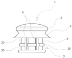
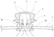
도 1은 본 고안의 구성 예를 보이는 정면 예시도.
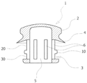
도 2는 도 1의 종단면 예시도.
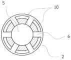
도 3은 도 1의 횡단면 예시도.
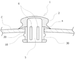
도 4는 본 고안의 밸브를 밀폐상태로 위치시킨 상태를 보이는 도면.
도 5는 본 고안의 밸브를 개방상태로 위치시킨 상태를 보이는 도면.1 is a front view illustrating a configuration example of the present invention.
Figure 2 is a longitudinal cross-sectional view of Figure 1;
3 is a cross-sectional view of FIG. 1.
Figure 4 is a view showing a state in which the valve of the present invention in a closed state.
5 is a view showing a state in which the valve of the present invention in the open position.
도 1에서 도시한 바와 같이 본 고안의 밀폐식 냄비용 에어 배출밸브(1)는,As shown in FIG. 1, the
상기 밀폐식 냄비용 에어 배출밸브(1)를 뚜껑(C)의 결착용 구멍에 끼워 결합시킬 수 있도록 합성수지재질의 본체(2)의 몸통 외주연에 환형으로 요입 구성되는 삽지요부(3)과, 밀폐식 냄비 내부의 에어 배출 기능만을 갖도록 상기 삽지요부(3)의 상면에 일체로 형성되는 환형의 역지 플랜지부(4)와, 냄비 내부의 에어가 배출되는 통로를 구성할 수 있도록 본체(2)의 내부에 하향으로 개방되는 입구를 갖도록 형성되는 중공부(5) 및 상기 중공부(5)와 연통할 수 있도록 상기 삽지요부(3)의 수직면(3')에 관통 형성되는 다수의 배기용 통공(6)을 포함하는 공지의 구조에 있어서,An inserting portion (3) formed in an annular indent in the outer periphery of the body of the main body (2) of synthetic resin so that the sealed pot air discharge valve (1) can be inserted into the binding hole of the lid (C); The
상기 삽지요부(3)의 수직면(3') 외주연에 횡으로 걸림턱(10)을 일체로 돌출 구성하여 걸림턱(10)을 기준으로 상, 하부 삽지홈(20)(30)을 분할 구성토록 함을 특징으로 한다.The upper and
이와 같이 구성되는 본 고안의 작용을 상세히 설명하면 다음과 같다.If described in detail the operation of the subject innovation is configured as follows.
본 고안의 에어 배출밸브(1)는 본체(1)의 하단을 수축시켜 상부 또는 하부 삽지홈(20)(30)중 하나에 뚜껑(C)이 끼워지도록 결합하게 되는 것으로,The
본 고안의 재질은 뛰어난 탄성 복원력과 밀착력, 내수, 내열성이 우수한 특성을 갖는 실리콘 수지계통이나 고무계통 등이 주로 이용될 수 있다.As the material of the present invention, a silicone resin system or a rubber system having excellent elastic restoring force and adhesion, water resistance, and heat resistance characteristics may be mainly used.
도 4는 본 고안 에어 배출밸브(1)의 상부 삽지홈(20)에 뚜껑(C)이 결합 위치된 상태를 보이는 것으로, 역지 플랜지부(4)는 에어 배출밸브(1)의 자중에 의해 뚜껑(C)의 표면에 밀착되어 있는 상태로서 냄비의 내, 외부로의 공기유통이 차단된 상태로서 외부의 이물질이 냄비의 내부로 유입될 수 없는 상태이다.4 shows a state in which the lid C is coupled to the upper
이 상태에서 음식물을 조리하기 위하여 냄비를 가열하게 되면 공기의 팽창으로 인하여 냄비의 내부에 고압이 발생하게 되고 이로 인해 고압의 공기는 중공부(5)를 통해 배기용 통공(6)으로 유입되면서 역지 플랜지부(3)를 강제적으로 들춰 올리면서 외부로 배출되는 것이며, 내압이 완전히 배출되면 역지 플랜지부(4)는 에어 배출밸브(1)의 자중에 의해 자동적으로 뚜껑의 표면에 밀착되면서 냄비의 내부를 밀폐하게 되는 것이다.In this state, when the pot is heated to cook food, high pressure is generated inside the pot due to the expansion of the air, whereby the high pressure air is introduced into the exhaust through-
이와 같이 냄비의 내부에서 발생된 내압이 역지 플랜지부(4)를 변형시키면서 그 틈을 통해 외부로 배출되는 과정은 본인의 선 등록 고안에서도 유사하게 이루어짐은 물론이다.As described above, the process of discharging the internal pressure generated inside the pot to the outside through the gap while deforming the
한편 도 4에서와 같은 에어 배출밸브(1)의 밀폐상태에서 삶거나 끓이는 국물 요리를 함으로써 내용물이 끓어 넘칠 우려가 있는 경우에는 미리 에어 배출밸브(1)의 밀폐상태를 해제시켜 내용물의 넘침을 방지하게 되는 것으로, 이를 위해 먼저 에어 배출밸브(1)를 잡고 위로 당겨주게 되면 당김력에 의해 걸림턱(10)이 변형됨과 동시에 수직면(3')이 수축되면서 걸림턱(10)이 뚜껑(C)의 결착용 구멍을 통과하여 상부로 노출되고 이와 동시에 변형 압력이 없어진 걸림턱(10)과 수직면(3')은 자체적인 탄성력으로 원형 복귀되어 도 5에서와 같이 하부 삽지홈(30)에 뚜껑(C)이 결합 위치하게 된다.On the other hand, when there is a risk that the contents boil over by cooking the boiling or boiling broth in the sealed state of the
이와 같이 위로 뽑혀진 상태로 유지된 에어 배출밸브(1)는 배기용 통공(6)과 역지 플랜지부(4)가 뚜껑(C)의 외부로 노출되어 냄비의 내부가 외부와 연통되어 개방상태를 유지하고 있는 상태가 되며 이와 같은 도 5의 상태에서는 삶거나 끓이는 국물 요리를 함으로써 내용물이 끓어 넘칠 우려가 있는 경우에도 이미 배기용 통공(6)의 전부가 최대한의 개방상태를 유지하게 됨으로써 충분한 개방공간을 확보할 수 있어 내용물의 가열시 발생되는 많은 량의 고압을 충분하고도 여유있게 배출시키는 것이 가능하여 내용물의 넘침을 방지하게 되는 것이다.The
한편 끓어 넘침의 우려가 적거나 내압의 발생이 적은 단순한 조리 방식의 경우 또는 그 외 밀폐상태를 유지할 필요성이 있는 경우에는 에어 배출밸브(1)를 잡고 밑으로 눌러 주게 되면 누름 압력에 의해 걸림턱(10)이 변형됨과 동시에 수직면(3')이 수축되면서 걸림턱(10)이 뚜껑(C)의 결착용 구멍을 통과하여 저부로 노출되고 이와 동시에 변형 압력이 없어진 걸림턱(10)과 수직면(3')은 자체적인 탄성력으로 원형 복귀되어 도 4에서와 같이 상부 삽지홈(20)에 뚜껑(C)이 결합 위치하게 된다.On the other hand, in the case of a simple cooking method which is less likely to boil over or less in the internal pressure, or when there is a need to maintain the sealed state, if the air discharge valve (1) is pressed and pressed downwards, 10 is deformed and the vertical surface 3 'is contracted and the
이상에서는, 본 고안의 일실시 예를 설명하였지만, 본 고안이 속하는 기술 분야에서 통상의 지식을 가진 자가 본 고안의 기술적 사상을 벗어나지 않는 범위 내에서 변경 및 변형한 것도 본 고안의 권리범위에 속함은 당연하다.In the above, an embodiment of the present invention has been described, but modifications and variations within the scope without departing from the technical spirit of the present invention by those of ordinary skill in the art belong to the scope of the present invention Of course.
1:밀폐식 냄비용 에어 배출밸브 2:본체
3:삽지요부 4:역지 플랜지부
5:중공부 6:배기용 통공
10:걸림턱 20:상부 삽지홈
30:하부 삽지홈1: Air exhaust valve for airtight pot 2: Body
3: Insertion part 4: Check flange part
5: Hollow department 6: Vent for exhaust
10: jam jaw 20: upper insertion groove
30: lower insertion groove
Claims (1)
상기 삽지요부(3)의 수직면(3') 외주연에 횡으로 걸림턱(10)을 일체로 돌출 구성하여 이 걸림턱(10)을 기준으로 상, 하부 삽지홈(20)(30)을 분할 구성토록 함을 특징으로 하는 밀폐식 냄비용 에어 배출밸브.An inserting portion (3) formed in an annular indent in the outer periphery of the body of the main body (2) of synthetic resin so that the sealed pot air discharge valve (1) can be inserted into the binding hole of the lid (C); The main body 2 to form an annular check flange portion 4 integrally formed on the upper surface of the inserting portion 3 so as to have only the air discharge function inside the sealed pot, and a passage through which the air inside the pot is discharged. Hollow part 5 formed to have an inlet opening downward in the interior of the plurality of exhaust through-holes formed in the vertical surface (3 ') of the insertion portion (3) to communicate with the hollow portion (5) In the well-known structure containing (6),
The upper and lower insertion grooves 20 and 30 are divided based on the locking jaw 10 by integrally protruding the locking jaw 10 integrally from the outer circumference of the vertical surface 3 'of the insertion section 3. Air discharge valve for sealed pot characterized in that the configuration.
Priority Applications (1)
| Application Number | Priority Date | Filing Date | Title |
|---|---|---|---|
| KR2020100013515U KR20120004891U (en) | 2010-12-27 | 2010-12-27 | the air valve of the sealing type pot |
Applications Claiming Priority (1)
| Application Number | Priority Date | Filing Date | Title |
|---|---|---|---|
| KR2020100013515U KR20120004891U (en) | 2010-12-27 | 2010-12-27 | the air valve of the sealing type pot |
Publications (1)
| Publication Number | Publication Date |
|---|---|
| KR20120004891U true KR20120004891U (en) | 2012-07-05 |
Family
ID=46853010
Family Applications (1)
| Application Number | Title | Priority Date | Filing Date |
|---|---|---|---|
| KR2020100013515U KR20120004891U (en) | 2010-12-27 | 2010-12-27 | the air valve of the sealing type pot |
Country Status (1)
| Country | Link |
|---|---|
| KR (1) | KR20120004891U (en) |
Cited By (1)
| Publication number | Priority date | Publication date | Assignee | Title |
|---|---|---|---|---|
| CN111281134A (en) * | 2020-04-02 | 2020-06-16 | 小熊电器股份有限公司 | Pot cover and micro-pressure pot providing pressure limiting and exhausting |
-
2010
- 2010-12-27 KR KR2020100013515U patent/KR20120004891U/en not_active Application Discontinuation
Cited By (2)
| Publication number | Priority date | Publication date | Assignee | Title |
|---|---|---|---|---|
| CN111281134A (en) * | 2020-04-02 | 2020-06-16 | 小熊电器股份有限公司 | Pot cover and micro-pressure pot providing pressure limiting and exhausting |
| CN111281134B (en) * | 2020-04-02 | 2024-05-17 | 小熊电器股份有限公司 | Pot cover and micro-pressure cooker for providing pressure-limiting exhaust |
Similar Documents
| Publication | Publication Date | Title |
|---|---|---|
| AU2014319872B2 (en) | Pressure cooker | |
| WO2014077620A1 (en) | Vacuum packing for food container | |
| KR20090068085A (en) | Pot lid handle | |
| KR101332512B1 (en) | A lid for cooker | |
| KR101993191B1 (en) | The check valve for cooking pan which has a vacuum function | |
| KR101136091B1 (en) | Boil-over preventing lid for cooking receptacle | |
| JP2008301996A (en) | Rice cooker | |
| KR20120004891U (en) | the air valve of the sealing type pot | |
| KR101409033B1 (en) | A lid for cool pot having overflow preventing function | |
| KR20080011738A (en) | Steam vent valve of cooking pan | |
| KR200152284Y1 (en) | The automatic valve structurt for releasing the steam in the pressure cooker | |
| KR101381740B1 (en) | Rice cooker using pressure | |
| KR101436886B1 (en) | packing for vacuum pot lid | |
| KR101325784B1 (en) | Packing-combination structure of a sealed pot | |
| JP5635537B2 (en) | Operation valve and pressure cooker | |
| KR101568168B1 (en) | lid for vacuum pot | |
| KR101795729B1 (en) | check valve and lid for vacuum pot in use with the check valve | |
| KR200443548Y1 (en) | The safety device of the electricity pressure rice kettle | |
| JP5306967B2 (en) | Hinge cap | |
| KR20170111304A (en) | Vacuum pot | |
| KR102338728B1 (en) | Vacuum pot | |
| KR101482075B1 (en) | lid of cooker | |
| TW201943989A (en) | Vacuum container valve | |
| CN214002670U (en) | Container sealing cover | |
| CN217828385U (en) | Device capable of effectively sealing smoke and quickly replacing moxa sticks |
Legal Events
| Date | Code | Title | Description |
|---|---|---|---|
| A201 | Request for examination | ||
| E902 | Notification of reason for refusal | ||
| E902 | Notification of reason for refusal |