KR20110097575A - Systems and methods for data recovery - Google Patents
Systems and methods for data recovery Download PDFInfo
- Publication number
- KR20110097575A KR20110097575A KR1020100065520A KR20100065520A KR20110097575A KR 20110097575 A KR20110097575 A KR 20110097575A KR 1020100065520 A KR1020100065520 A KR 1020100065520A KR 20100065520 A KR20100065520 A KR 20100065520A KR 20110097575 A KR20110097575 A KR 20110097575A
- Authority
- KR
- South Korea
- Prior art keywords
- data
- location
- circuit
- storage medium
- sync mark
- Prior art date
Links
Images


Classifications
-
- G—PHYSICS
- G11—INFORMATION STORAGE
- G11B—INFORMATION STORAGE BASED ON RELATIVE MOVEMENT BETWEEN RECORD CARRIER AND TRANSDUCER
- G11B20/00—Signal processing not specific to the method of recording or reproducing; Circuits therefor
- G11B20/10—Digital recording or reproducing
- G11B20/18—Error detection or correction; Testing, e.g. of drop-outs
- G11B20/1816—Testing
-
- G—PHYSICS
- G11—INFORMATION STORAGE
- G11B—INFORMATION STORAGE BASED ON RELATIVE MOVEMENT BETWEEN RECORD CARRIER AND TRANSDUCER
- G11B5/00—Recording by magnetisation or demagnetisation of a record carrier; Reproducing by magnetic means; Record carriers therefor
- G11B5/48—Disposition or mounting of heads or head supports relative to record carriers ; arrangements of heads, e.g. for scanning the record carrier to increase the relative speed
- G11B5/58—Disposition or mounting of heads or head supports relative to record carriers ; arrangements of heads, e.g. for scanning the record carrier to increase the relative speed with provision for moving the head for the purpose of maintaining alignment of the head relative to the record carrier during transducing operation, e.g. to compensate for surface irregularities of the latter or for track following
- G11B5/596—Disposition or mounting of heads or head supports relative to record carriers ; arrangements of heads, e.g. for scanning the record carrier to increase the relative speed with provision for moving the head for the purpose of maintaining alignment of the head relative to the record carrier during transducing operation, e.g. to compensate for surface irregularities of the latter or for track following for track following on disks
- G11B5/59605—Circuits
- G11B5/59616—Synchronisation; Clocking
-
- H—ELECTRICITY
- H03—ELECTRONIC CIRCUITRY
- H03M—CODING; DECODING; CODE CONVERSION IN GENERAL
- H03M13/00—Coding, decoding or code conversion, for error detection or error correction; Coding theory basic assumptions; Coding bounds; Error probability evaluation methods; Channel models; Simulation or testing of codes
- H03M13/33—Synchronisation based on error coding or decoding
-
- G—PHYSICS
- G11—INFORMATION STORAGE
- G11B—INFORMATION STORAGE BASED ON RELATIVE MOVEMENT BETWEEN RECORD CARRIER AND TRANSDUCER
- G11B20/00—Signal processing not specific to the method of recording or reproducing; Circuits therefor
- G11B20/10—Digital recording or reproducing
- G11B20/12—Formatting, e.g. arrangement of data block or words on the record carriers
- G11B2020/1264—Formatting, e.g. arrangement of data block or words on the record carriers wherein the formatting concerns a specific kind of data
- G11B2020/1265—Control data, system data or management information, i.e. data used to access or process user data
- G11B2020/1287—Synchronisation pattern, e.g. VCO fields
-
- G—PHYSICS
- G11—INFORMATION STORAGE
- G11B—INFORMATION STORAGE BASED ON RELATIVE MOVEMENT BETWEEN RECORD CARRIER AND TRANSDUCER
- G11B20/00—Signal processing not specific to the method of recording or reproducing; Circuits therefor
- G11B20/10—Digital recording or reproducing
- G11B20/14—Digital recording or reproducing using self-clocking codes
- G11B20/1403—Digital recording or reproducing using self-clocking codes characterised by the use of two levels
- G11B2020/1476—Synchronisation patterns; Coping with defects thereof
-
- G—PHYSICS
- G11—INFORMATION STORAGE
- G11B—INFORMATION STORAGE BASED ON RELATIVE MOVEMENT BETWEEN RECORD CARRIER AND TRANSDUCER
- G11B20/00—Signal processing not specific to the method of recording or reproducing; Circuits therefor
- G11B20/10—Digital recording or reproducing
- G11B20/18—Error detection or correction; Testing, e.g. of drop-outs
- G11B20/1833—Error detection or correction; Testing, e.g. of drop-outs by adding special lists or symbols to the coded information
- G11B2020/185—Error detection or correction; Testing, e.g. of drop-outs by adding special lists or symbols to the coded information using an low density parity check [LDPC] code
Abstract
본 발명의 다양한 실시예는 저장 매체 상의 재생가능 로케이션을 식별하는 시스템 및 방법을 제공한다. 예를 들어, 매체 결함 검출기와 앵커 고정 회로를 포함하는 회로가 설명된다. 매체 결함 검출기는 매체 결함을 식별하도록 동작가능하고 앵커 고정 회로는 매체 결함에 관련된 로케이션을 식별하도록 동작가능하다. 이 로케이션은 재생가능하다.Various embodiments of the present invention provide a system and method for identifying a reproducible location on a storage medium. For example, a circuit including a media defect detector and an anchor fixing circuit is described. The media defect detector is operable to identify a media defect and the anchor fixing circuit is operable to identify a location related to the media defect. This location is playable.

Description
본 발명은 저장 매체 상의 재생가능 로케이션을 식별하는 시스템 및 방법에 관한 것으로서, 보다 구체적으로는 검출된 매체 결함에 기초하여 저장 매체 상의 재생가능 로케이션을 식별하는 시스템 및 방법에 관한 것이다.
The present invention relates to a system and method for identifying a reproducible location on a storage medium, and more particularly to a system and method for identifying a reproducible location on a storage medium based on a detected media defect.
하드디스크는 일반적으로 프리앰블 및 데이터 동기 패턴을 포함하는 동기화 정보가 선행되는 다수의 사용자 데이터 영역을 포함한다. 프리앰블은 비동기식 판독 동안 위상 및 주파수를 동기화시키는 데 이용되고, 데이터 동기 패턴은 일련의 사용자 데이터의 시작점을 정의하는 데 이용된다. 동작 시, 회로는 데이터 동기 패턴을 검색하고, 데이터 동기 패턴에 관련된 로케이션에서 유도된 일련의 후속 수신 데이터 샘플을 처리한다. 때때로, 데이터 동기 패턴은 누락되어, 하나 이상의 검색 방안이 데이터 동기 패턴을 식별하는 데 이용되는 리트라이(retry)를 야기한다. 이러한 검색 방안은 흔히 회로 및 시간적인 면에서 비용이 많이 든다. 또한, 몇몇 경우, 그 검색 방안은 데이터 동기 마크를 식별할 수 없어, 데이터 손실을 야기한다.Hard disks generally include a plurality of user data areas preceded by synchronization information, including preambles and data synchronization patterns. The preamble is used to synchronize phase and frequency during asynchronous readout, and the data sync pattern is used to define the starting point of a series of user data. In operation, the circuit retrieves the data sync pattern and processes a series of subsequent received data samples derived at a location related to the data sync pattern. Occasionally, data synchronization patterns are missing, causing a retry in which one or more search schemes are used to identify the data synchronization pattern. Such search schemes are often expensive in terms of circuitry and time. In addition, in some cases, the search scheme cannot identify the data sync mark, resulting in data loss.
따라서, 적어도 전술한 이유로 인해, 본 분야에서는 저장 매체로부터 데이터를 복구하는 개선된 시스템 및 방법이 필요하다.
Thus, for at least the reasons described above, there is a need in the art for an improved system and method for recovering data from a storage medium.
본 발명은 저장 매체 상의 재생가능 로케이션을 식별하는 시스템 및 방법에 관한 것으로서, 보다 구체적으로는 검출된 매체 결함에 기초하여 저장 매체 상의 재생가능 로케이션을 식별하는 시스템 및 방법에 관한 것이다.The present invention relates to a system and method for identifying a reproducible location on a storage medium, and more particularly to a system and method for identifying a reproducible location on a storage medium based on a detected media defect.
본 발명의 다양한 실시예는 저장 매체 상의 재생가능 로케이션을 식별하는 회로를 제공한다. 이러한 회로는 매체 결함 검출기 및 앵커 고정 회로를 포함한다. 매체 결함 검출기는 매체 결함을 식별하도록 동작가능하고, 앵커 고정 회로는 매체 결함에 관련된 재생가능 로케이션을 식별하도록 동작가능하다. 몇몇 경우, 매체 결함 검출기는 2T 패턴으로 튜닝되는 이산 푸리에 변환 회로를 포함한다. 다른 경우, 매체 결함 검출기는 프리앰블 검출기 회로의 단부를 포함한다.Various embodiments of the present invention provide circuitry for identifying a reproducible location on a storage medium. Such a circuit includes a medium defect detector and an anchor fixing circuit. The media defect detector is operable to identify a media defect and the anchor fixing circuit is operable to identify a reproducible location associated with the media defect. In some cases, the media defect detector includes a discrete Fourier transform circuit tuned in a 2T pattern. In other cases, the media defect detector includes an end of the preamble detector circuit.
전술한 실시예의 몇몇 실례에서, 매체 결함 검출기는 저장 매체로부터 유도된 일련의 데이터 샘플을 이용하여 매체 결함을 식별하도록 동작가능하다. 이러한 실례에서, 그 회로는 매체 결함의 로케이션으로부터의 고정 거리인 강제된 데이터 동기 마크를 이용하여 일련의 데이터 샘플의 서브세트를 처리하도록 동작가능한 데이터 처리 회로를 더 포함한다. 이러한 몇몇 실례에서, 그 회로는, 데이터 처리 회로가 수렴하지 못하는 경우에는 강제된 데이터 동기 마크를 반복해서 식별하고 데이터 처리 회로가 수렴하는 경우에는 강제된 데이터 동기 마크를 저장하는 동기 강제 회로를 더 포함한다. 특정 실례에서, 그 회로는 저장 매체 상에서 디코딩가능 데이터 세트의 시작부를 나타내도록 저장 매체로부터의 후속 판독 시에 이용가능한 동기 데이터를 저장하는 데이터 버퍼를 더 포함한다.In some examples of the foregoing embodiments, the media defect detector is operable to identify the media defect using a series of data samples derived from the storage medium. In this example, the circuit further includes data processing circuitry operable to process a subset of the series of data samples using a forced data sync mark that is a fixed distance from the location of the media defect. In some such examples, the circuit further includes a synchronous forcing circuit that repeatedly identifies the forced data sync mark if the data processing circuit fails to converge and stores the forced data sync mark if the data processing circuit converges. do. In a particular example, the circuit further includes a data buffer that stores the synchronous data available upon subsequent reading from the storage medium to indicate the beginning of the decodable data set on the storage medium.
본 발명의 다른 실시예는 저장 매체 상의 재생가능 로케이션을 식별하는 방법을 제공한다. 그 방법은, 저장 매체로부터 유도되는 일련의 데이터 샘플을 수신하는 단계와, 그 일련의 데이터 샘플을 이용하여 저장 매체 상의 매체 결함을 식별하는 단계와, 그 매체 결함에 관련된 저장 매체 상의 재생가능 로케이션을 고정하거나 식별하는 단계를 포함한다. 몇몇 실례에서, 그 방법은 디코딩가능 데이터 세트의 시작에 대한 기준으로서 그 로케이션을 이용하여 일련의 데이터 샘플의 서브세트에 디코딩 알고리즘을 적용하는 단계를 더 포함한다. 디코딩 알고리즘이 수렴하는 이러한 몇몇 실례에서, 그 방법은, 메모리에 강제된 데이터 동기 마크를 저장하는 단계를 더 포함한다. 강제된 데이터 동기 마크는 로케이션을 나타내며, 저장 매체 상의 디코딩가능 데이터 세트의 시작부를 나타내도록 저장 매체로부터의 후속 판독 시에 이용가능하다.Another embodiment of the invention provides a method of identifying a reproducible location on a storage medium. The method includes receiving a series of data samples derived from a storage medium, using the series of data samples to identify a media defect on the storage medium, and reproducing a location on the storage medium associated with the media defect. Fixing or identifying. In some instances, the method further includes applying the decoding algorithm to a subset of the series of data samples using the location as a reference for the start of the decodable data set. In some such instances where the decoding algorithm converges, the method further includes storing the forced data sync mark in memory. The forced data sync mark indicates a location and is available on subsequent reads from the storage medium to indicate the beginning of the decodable data set on the storage medium.
전술한 실시예의 다양한 실례에서, 그 로케이션은 제 1 로케이션이고, 그 방법은 디코딩가능 데이터 세트의 시작에 대한 기준으로서 제 1 로케이션을 이용하여 일련의 데이터 샘플의 제 1 서브세트에 디코딩 알고리즘을 적용하는 단계를 더 포함한다. 디코딩 알고리즘이 수렴하지 않는 경우, 방법은 매체 결함에 관련된 저장 매체 상의 재생가능 제 2 로케이션을 고정하는 단계와, 디코딩가능 데이터 세트의 시작에 대한 기준으로서 제 2 로케이션을 이용하여 일련의 데이터 샘플의 제 2 서브세트에 디코딩 알고리즘을 적용하는 단계를 더 포함한다. 몇몇 실례에서, 제 2 로케이션을 이용한 디코딩 알고리즘의 적용은 수렴한다. 이들 경우, 방법은 강제된 데이터 동기 마크를 메모리에 저장하는 단계를 더 포함할 수 있다. 강제된 데이터 동기 마크는 제 2 로케이션을 나타내며 저장 매체로부터의 후속 판독에 사용되어 저장 매체 상의 디코딩가능 데이터 세트의 시작부를 나타낼 수 있다. 하나의 특정 경우, 제 2 로케이션은 제 1 로케이션보다 매체 결함으로부터 멀리 떨어져 있다.In various examples of the foregoing embodiments, the location is a first location, and the method applies the decoding algorithm to a first subset of the series of data samples using the first location as a reference for the start of the decodable data set. It further comprises a step. If the decoding algorithm does not converge, the method may further include fixing the reproducible second location on the storage medium associated with the media defect, and using the second location as a reference for the start of the decodable data set. Applying the decoding algorithm to the two subsets. In some instances, the application of the decoding algorithm using the second location converges. In these cases, the method may further comprise storing the forced data sync mark in a memory. The forced data sync mark may indicate a second location and be used for subsequent reading from the storage medium to indicate the beginning of a decodable data set on the storage medium. In one particular case, the second location is farther from the media defect than the first location.
전술한 실시예의 다양한 실례에서, 디코딩 알고리즘은 저밀도 패리티 체크 알고리즘이다. 전술한 실시예의 하나 이상의 실례에서, 저장 매체로부터 유도된 일련의 데이터 샘플을 수신하는 단계는 데이터 버퍼로부터 일련의 데이터 샘플을 액세스하는 단계를 포함한다. 몇몇 경우, 그 방법은 저장 매체로부터의 정보를 액세스하는 단계와, 그 정보에 기초하여 일련의 데이터 샘플을 생성하는 단계를 더 포함한다.In various examples of the foregoing embodiments, the decoding algorithm is a low density parity check algorithm. In one or more examples of the foregoing embodiments, receiving the series of data samples derived from the storage medium includes accessing the series of data samples from the data buffer. In some cases, the method further includes accessing information from the storage medium and generating a series of data samples based on the information.
본 발명의 또 다른 실시예는 저장 매체, 매체 결함 검출기 및 앵커 고정 회로를 포함하는 하드디스크 드라이브 시스템을 제공한다. 매체 결함 검출기는 저장 매체로부터 유도된 일련의 데이터 샘플을 이용하여 저장 매체 상의 매체 결함을 식별하도록 동작가능하고, 앵커 고정 회로는 매체 결함에 관련된 로케이션을 식별하도록 동작가능하다. 이러한 경우, 로케이션은 재생가능하다.Yet another embodiment of the present invention provides a hard disk drive system including a storage medium, a media defect detector, and an anchor fixing circuit. The media defect detector is operable to identify a media defect on the storage medium using a series of data samples derived from the storage medium, and the anchor fixing circuit is operable to identify a location related to the media defect. In this case, the location is reproducible.
이 요약은 본 발명의 몇몇 실시예의 전반적인 개요만을 제공한다. 본 발명의 수많은 다른 목적, 특징, 이점 및 다른 실시예는 다음의 상세한 설명, 첨부된 특허청구범위 및 첨부된 도면으로부터 더욱 충분히 명백해질 것이다.
This summary only provides a general overview of some embodiments of the invention. Numerous other objects, features, advantages, and other embodiments of the present invention will become more fully apparent from the following detailed description, the appended claims, and the accompanying drawings.
본 발명의 다양한 실시예의 추가 이해는 명세서의 나머지 부분에 설명되는 도면을 참조하여 구현될 수 있다. 도면에서, 유사한 참조번호는 여러 도면 전체에서 유사한 콤포넌트를 지칭하는 데 이용된다. 몇몇 경우, 하위 경우의 문자로 이루어진 서브라벨은 참조번호와 연계되어 다수의 유사한 콤포넌트 중 하나를 표기한다. 기존의 서브라벨에 대한 명세 없이 참조번호가 지칭되는 경우는 그러한 다수의 유사한 콤포넌트 모두를 지칭하고자 하는 것이다.
도 1a는 본 발명의 다양한 실시예에 따라 앵커 지점 회로 및 데이터 동기 마크 강제 회로를 포함하는 판독 채널을 도시한 도면,
도 1b는 본 발명의 몇몇 실시예에 따라 도 1a의 판독 채널 회로의 예시적 동작을 도시하는 타이밍도,
도 2는 본 발명의 다양한 실시예에 따른 이산 푸리에 변환 기반 앵커 로케이션 회로를 도시한 도면,
도 3은 본 발명의 다른 실시예에 따른 프리앰블 기반 앵커 로케이션 회로의 단부를 도시한 도면,
도 4a 및 도 4b는 본 발명의 하나 이상의 실시예에 따라 앵커 지점을 고정하고 그 앵커 지점에 관련되는 데이터 동기 마크를 강제하는 본 발명의 실시예에 따른 방법을 도시한 흐름도,
도 5는 본 발명의 몇몇 실시예에 따른 앵커 지점 회로 및 동기 마크 강제 회로와 함께 판독 채널을 포함한 저장 시스템을 도시한 도면이다.Further understanding of various embodiments of the present invention may be implemented with reference to the drawings described in the remainder of the specification. In the drawings, like reference numerals are used to refer to like components throughout the several views. In some cases, a sublabel consisting of letters in the subcase designates one of a number of similar components in conjunction with a reference number. Where reference is made to the specification without reference to existing sublabels, it is intended to refer to all such many similar components.
1A illustrates a read channel including an anchor point circuit and a data sync mark forcing circuit, in accordance with various embodiments of the invention;
FIG. 1B is a timing diagram illustrating exemplary operation of the read channel circuit of FIG. 1A, in accordance with some embodiments of the present disclosure. FIG.
2 illustrates a discrete Fourier transform based anchor location circuit according to various embodiments of the present disclosure;
3 illustrates an end of a preamble based anchor location circuit in accordance with another embodiment of the present invention;
4A and 4B are flow diagrams illustrating a method according to an embodiment of the present invention for fixing an anchor point and forcing a data sync mark associated with the anchor point in accordance with one or more embodiments of the present invention;
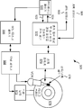
5 is a diagram of a storage system including a read channel along with an anchor point circuit and a sync mark forcing circuit in accordance with some embodiments of the invention.
본 발명은 저장 매체 상의 재생가능 로케이션을 식별하는 시스템 및 방법에 관한 것으로서, 보다 구체적으로는 검출된 매체 결함에 기초하여 저장 매체 상의 재생가능 로케이션을 식별하는 시스템 및 방법에 관한 것이다.The present invention relates to a system and method for identifying a reproducible location on a storage medium, and more particularly to a system and method for identifying a reproducible location on a storage medium based on a detected media defect.
본 발명의 다양한 실시예는 저장 매체 또는 몇몇 다른 이형물 상의 매체 결함으로 인해 저장 매체 상에서 검출될 수 없는 오리지널 데이터 동기 마크를 대신하여 이용될 수 있는 강제된 데이터 동기 마크를 제공한다. 한 가지 특정 경우, 강제된 데이터 동기 마크는 저장 매체 상의 매체 결함으로부터 정의된 거리만큼 떨어져 위치한다. 매체 결함이 움직이지 않기 때문에, 매체 결함의 로케이션은 재생가능하다. 매체 결함의 로케이션이 재생가능하고 강제된 데이터 동기 마크가 매체 결함에 관련되어 위치하기 때문에, 강제된 데이터 동기 마크도 재생가능하다. 동시적 데이터 마크의 재생가능성은 강제된 데이터 동기 마크가 그것의 유용성을 판정하도록 테스트되게 하며, 일단 유용한 것으로 증명되면, 강제된 데이터 동기 마크는 추후 저장 매체로부터 데이터를 판독하는 데 이용될 수 있다.Various embodiments of the present invention provide a forced data sync mark that can be used in place of an original data sync mark that cannot be detected on a storage medium due to a media defect on the storage medium or some other variant. In one particular case, the forced data sync mark is located a defined distance away from the media defect on the storage medium. Since the media defect does not move, the location of the media defect is reproducible. Because the location of the media defect is reproducible and the forced data sync mark is located in association with the media defect, the forced data sync mark is also playable. The reproducibility of the concurrent data marks causes the forced data sync mark to be tested to determine its usefulness, and once proven useful, the forced data sync mark can be used to read data from the storage medium later.
본 발명의 몇몇 실시예는 저장 매체 상의 재생가능 로케이션을 식별하는 회로를 제공한다. 이러한 회로는 매체 결함 검출기 및 앵커 고정 회로를 포함한다. 본 명세서에서 이용되는 바와 같이, "매체 결함 검출기"라는 구문은 가장 넓은 관점에서 저장 매체 상의 매체 결함의 로케이션을 나타낼 수 있는 임의의 회로, 디바이스 또는 시스템을 의미하는 데 이용된다. 본 명세서에서 이용되는 바와 같이, "앵커 고정 회로"라는 구문은 가장 넓은 관점에서 식별된 매체 결함에 관련된 재생가능 로케이션을 식별할 수 있는 임의의 회로, 디바이스 또는 시스템을 의미하는 데 이용된다.Some embodiments of the present invention provide circuitry for identifying a reproducible location on a storage medium. Such a circuit includes a medium defect detector and an anchor fixing circuit. As used herein, the phrase “media defect detector” is used to mean any circuit, device, or system that can represent the location of a media defect on a storage medium in its broadest sense. As used herein, the phrase “anchor lock circuit” is used in the broadest sense to mean any circuit, device or system capable of identifying a reproducible location associated with a media defect identified.
전술한 실시예의 몇몇 경우, 그 회로는 데이터 처리 회로를 더 포함할 수 있다. 본 명세서에서 이용되는 바와 같이, "데이터 처리 회로"라는 구문은 가장 넓은 관점에서 데이터 입력에 정의된 프로세스를 적용하여 데이터 출력을 안출할 수 있는 임의의 회로를 의미하는 데 이용된다. 몇몇 경우, 정의된 프로세스는 데이터 검출기 알고리즘 및/또는 데이터 디코더 알고리즘이다. 한 가지 특정한 경우, 데이터 입력이 기지의 로케이션으로부터 시작하여 너무 많은 에러 비트를 갖지 않을 때 적절한 결과에 수렴하는 저밀도 패리티 체크 디코더 알고리즘이 이용된다. 본 명세서에 제공되는 개시에 기초하여, 당업자라면, 본 발명의 상이한 실시예와 관련하여 이용될 수 있는 다양한 데이터 디코더 및/또는 데이터 검출기 회로를 인지할 것이다.In some cases of the foregoing embodiments, the circuit may further include a data processing circuit. As used herein, the phrase “data processing circuit” is used in its broadest sense to mean any circuit capable of producing a data output by applying a process defined for data input. In some cases, the defined process is a data detector algorithm and / or a data decoder algorithm. In one particular case, a low density parity check decoder algorithm is used that converges to the proper result when the data input starts from a known location and does not have too many error bits. Based on the disclosure provided herein, those skilled in the art will recognize various data decoder and / or data detector circuits that may be used in connection with different embodiments of the present invention.
데이터 처리 회로는 검출되지 않은 오리지널 데이터 동기 마크를 대신하여 강제된 데이터 동기 마크로 시작하는 데이터를 수신할 수 있다. 강제된 데이터 동기 마크가 오리지널 데이터 동기 마크와 동일한 로케이션에 있는 경우, 데이터 처리 회로는 너무 많은 데이터 에러가 있는 것이 아닐 때 수렴해야 한다. 반대로, 강제된 데이터 동기 마크가 오리지널 데이터 동기 마크와 동일한 로케이션에 있지 않은 경우, 데이터 처리 회로가 수렴할 것이라는 것은 거의 가능하지 않다. 따라서, 매체 결함에 대응하는 앵커 로케이션을 식별한 후, 본 발명의 몇몇 실시예는 데이터 처리 회로가 수렴할 때까지 앵커 로케이션에 관련된 상이한 로케이션에 강제된 데이터 동기 마크를 위치시킨다. 데이터 처리 회로가 수렴하는 경우, 강제된 데이터 동기 마크가 적절한 로케이션에 위치한다는 것이 전제된다. 일단 데이터 처리 회로에 의해 데이터 수렴이 되는 강제된 데이터 동기 마크가 식별되면, 동시적 데이터 동기 마크의 로케이션은 검출불능 오리지널 데이터 동기 마크를 대신하여 저장 매체의 다음 판독 시에 이용될 수 있는 버퍼에 저장된다.The data processing circuit can receive data starting with a forced data sync mark in place of the original data sync mark that was not detected. If the forced data sync mark is at the same location as the original data sync mark, the data processing circuit must converge when there are not too many data errors. In contrast, if the forced data sync mark is not at the same location as the original data sync mark, it is hardly possible that the data processing circuit will converge. Thus, after identifying the anchor location corresponding to the media defect, some embodiments of the present invention place a forced data sync mark at a different location related to the anchor location until the data processing circuit converges. When the data processing circuit converges, it is assumed that the forced data sync mark is located at the appropriate location. Once the forced data sync mark that is data converged by the data processing circuit is identified, the location of the simultaneous data sync mark is stored in a buffer that can be used on the next read of the storage medium in place of the undetectable original data sync mark. do.
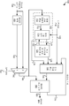
도 1a를 참조하면, 본 발명의 다양한 실시예에 따른 앵커 지점 회로 및 데이터 동기 마크 강제 회로를 포함하는 판독 채널 회로(100)가 도시되어 있다. 판독 채널 회로(100)는 앵커 로케이션 회로(110)를 포함한다. 앵커 로케이션 회로(110)는 출력(145)으로서 멀티플렉서(140)를 통해 디스크 또는 다른 저장 매체로부터 유도되는 데이터(105)를 수신하는 매체 결함 검출기 회로(112)를 구비한다. 몇몇 경우, 데이터(105)는, 예를 들어 저장 매체로부터의 정보를 감지하고 그 정보를 필터링하며, 그 정보를 일련의 대응 디지털 샘플에 수렴시키는 책임이 있는 아날로그 처리 회로(도시하지 않음)로부터 수신될 수 있는 일련의 데이터 샘플이다. 본 명세서에 제공되는 개시에 기초하여, 당업자라면, 데이터(105)에 대한 다양한 소스 및 사전처리 회로를 인지할 것이다.Referring to FIG. 1A, a
매체 결함 검출기 회로(112)는 멀티플렉서 출력(145)를 수신하고 매체 결함 출력(113)을 앵커 고정 회로(114)에 제공하도록 동작가능하다. 매체 결함 출력(113)은 데이터(105)가 유도된 매체 상의 검출된 결함에 대응하는 기간 동안 인가된다. 매체 결함 검출기 회로(112)는 데이터(105)가 유도된 매체 상의 결함의 발생을 나타내는 출력을 제공할 수 있는 본 분야에 알려져 있는 임의의 매체 결함 검출기 회로일 수 있다. 앵커 고정 회로(114)는 매체 결함 출력(113)에 필터링 알고리즘을 적용하여, 식별된 매체 결함의 로케이션 및 위상과 함께 현재 식별된 매체 결함이 충분히 신뢰될 수 있는 것인가를 판정한다. 매체 결함 출력(113)에 의해 나타내어진 현재 식별된 매체 결함이 충분히 신뢰될 수 없는 경우, 그것은 무시되고 다음 매체 결함이 대기된다. 대안으로, 매체 결함 출력(113)에 의해 나타내어진 현재 식별된 매체 결함이 충분히 신뢰될 수 있는 경우, 앵커 고정 회로(114)는 앵커 로케이션 및 위상 저장 회로(120)에 결함 및 위상 로케이션 출력(115)을 제공한다. 앵커 로케이션 및 위상 저장 회로(120)는 반복되는 강제된 데이터 동기 마크에 대한 앵커 지점으로서 이용될 수신된 위상 및 로케이션을 저장한다.The media
앵커 로케이션 및 위상 저장 회로(120)는 위상 출력(122)을 앵커 고정 회로(114)에 제공한다. 제 2 또는 추후의 리트라이가 리트라이 번호(125)로 나타내어지는 바와 같이 처리되는 언제든지, 앵커 고정 회로(114)만은 위상 출력(122)으로서 제공되는 이전에 결정된 위상을 이용하여 이전에 식별된 앵커 지점을 찾는다. 앵커 로케이션 및 위상 저장 회로(120)는 수신된 앵커 및 위상 출력(128)에 관련된 강제된 데이터 동기 출력(135)을 제공하는 동기 강제 회로(130)에 앵커 및 위상 출력(128)을 제공한다.The anchor location and
데이터(105)는 또한 데이터 처리 회로(160)에 의한 디코딩을 위해 적어도 하나의 전체 인코딩 데이터 세트를 저장하기에 충분한 크기의 데이터 버퍼(150)에 제공된다. 데이터(105)가 처음 수신되면, 리트라이 입력(142)은 데이터(105)가 멀티플렉싱된 출력(145)으로부터 멀티플렉서(140)를 통해 데이터 처리 회로(160) 및 매체 결함 검출기 회로(112)에 제공되도록 로직 '0'으로 설정된다. 오리지널 데이터 동기 마크가 검출되는 이 초기 처리 패스 시, 데이터 처리 회로(160)는 데이터(105)를 처리하여 데이터 출력(165)을 안출한다. 대안으로, 오리지널 데이터 동기 마크가 검출되지 않는 경우, 후속 패스는 버퍼링된 데이터(155)를 데이터 버퍼(150)로부터 멀티플렉서(140)를 통해 데이터 처리 회로(160) 및 매체 결함 검출기 회로(112)로 제공한다.
리트라이 번호(125)로 표시된 모든 리트라이 패스 시에, 동기 강제 회로(130)는 강제된 데이터 동기 마크(135)를 데이터 처리 회로(160)로 제공한다. 강제된 데이터 동기 마크(135)는 데이터 처리 회로(160)에 의해 처리될 데이터 버퍼(150) 내의 데이터의 재생가능 시작부를 나타내는 데 이용된다. 데이터 처리 회로(160)가 수렴하는 경우, 그 결과는 데이터 출력(165)으로서 제공되며, 이전에 강제된 데이터 동기 마크가 이용되었음을 나타내는 데이터 수렴 출력(170)이 인가된다. 이러한 경우, 동기 강제 회로(130)는 앵커 지점에 관련된 로케이션으로서 이전에 강제된 데이터 동기 마크를 저장한다. 이 로케이션 정보는 저장 매체의 대응 영역으로의 후속 액세스에 대해 이용될 수 있다. 이 때, 리트라이 프로세스는 데이터가 발견되었을 때 완료된다.In every retry pass indicated by the retry
대안으로, 데이터 처리 회로(160)가 수렴하지 않는 경우, 데이터 수렴 신호(170)는 그 실패를 나타내어 동기 강제 회로(130)로 수렴시킨다. 응답 시, 동기 강제 회로(130)는 후속하는 강제된 데이터 동기 마크를 이전에 강제된 데이터 동기 마크보다 앵커 지점으로부터 훨씬 더 먼 거리로 강제한다. 데이터 버퍼(150)로부터의 데이터는 이전에 기술한 바와 같이 데이터 처리 회로(160)에 의해 재처리된다. 출력(128)의 일부로서 수신되는 이전에 식별된 앵커 로케이션으로부터 후속하는 상이한 거리에 강제된 데이터 동기 마크를 반복적으로 배치하고 데이터 처리 회로(160)에 의한 처리를 리트라이하는 이 프로세스는 타임아웃 조건이 충족되거나 유효한 데이터 동기 마크 로케이션이 식별될 때까지(즉, 데이터 처리 회로(160)가 수렴할 때까지) 계속된다.Alternatively, if
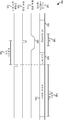
도 1b를 참조하면, 타이밍도(180)는 본 발명의 몇몇 실시예에 따른 판독 채널 회로(100)의 예시적 동작을 도시하고 있다. 타이밍도(180)에서, 디스크로부터의 데이터(즉, 멀티플렉서(140)로부터의 출력(145))는 본 분야에 알려져 있는 바와 같이 2T 프리앰블(192)을 포함한다. 2T 프리앰블(192)은 후속 오리지널 데이터 동기 마크(194) 및 사용자 데이터(188)의 위상 및 주파수를 동기화시키는 데 이용될 수 있는 반복 신호이다. 사용자 데이터는 동기 마크(194) 후에 시작되는 알려진 수의 비트(198)이다. 몇몇 실시예에서, 알려진 수의 비트(198)는 4K 비트이다. 도시한 바와 같이, 매체 결함(186)은 2T 프리앰블(192)이 매체 상에 저장되는 위치에서 발생한다. 판독 채널 회로는 매체 결함(186)이 2T 프리앰블(192) 및/또는 오리지널 데이터 동기 마크(194)의 어디에서든 발생하는 경우에 작동할 것이라는 점에 유의해야 한다.1B, timing diagram 180 illustrates exemplary operation of
매체 결함 출력(113)은 매체 결함(186)에 대응하는 기간(184) 동안에 인가된다. 일단 식별된 매체 결함이 충분히 신뢰할 수 있는 것으로 판별되면, 앵커 지점(128)은 강제된 데이터 동기 마크와 관련된 이용을 위해 저장된다. 도시한 바와 같이, 강제된 동기 마크(135)는 결국 오리지널 데이터 동기 마크(194)에 대응하는 로케이션에 위치한다. 강제된 동기 마크(135)의 로케이션은 앵커 지점(128)으로부터의 재생가능 거리(190)이다. 이와 같이, 강제된 데이터 동기 마크(135)는 사용자 데이터(188)의 후속 액세스에 대해 저장되고 재생될 수 있다. 시도된 다수의 강제된 동기 마크는 도시되지 않는다. 이들 조기 시도된 강제된 동기 마크는 정확하지 않기 때문에, 데이터 처리 회로(160)는 수렴하지 못하고 후속 강제된 데이터 동기 마크의 배치 및 시도를 야기하게 된다. 이 프로세스는 앵커 지점(128)으로부터의 재생가능 거리(190)에 대응하는 도시한 강제된 동기 마크(135)가 위치할 때까지 반복된다.
도 2를 참조하면, 이산 푸리에 변환 기반 앵커 로케이션 회로(200)가 본 발명의 다양한 실시예에 따라 도시된다. 앵커 로케이션 회로(200)는 도 1의 앵커 로케이션 회로를 대신하여 이용될 수 있다. 앵커 로케이션 회로(200)는 2T 주파수로 튜닝되는 이산 푸리에 변환 회로(210)를 포함한다. 이산 푸리에 변환 회로(210)는 본 분야에 알려져 있는 임의의 이산 푸리에 변환 회로일 수 있다. 본 분야에 알려져 있는 바와 같이, 2T 주파수는 주기 4T를 갖는 프리앰블 패턴의 기본 주파수로서, 이 때 T는 1 비트의 듀레이션을 표시한다. 이산 푸리에 변환 회로(210)는 데이터 입력(205)(x[n])을 수신하고, 데이터 입력(205)을 주파수 도메인 출력(215)(X[n])으로 변환한다. 한 가지 특정 실시예에서, 데이터 입력(205)은 도 1a에 도시한 멀티플렉서(140)로부터의 데이터 출력(145)일 수 있다. 주파수 도메인 출력(215)은 다음의 수학식에 의해 설명된다.Referring to FIG. 2, a discrete Fourier transform based
![]()
![]()
이동 에버리지 필터 회로(220)는 주파수 도메인 출력(215)을 수신하고 에버리지 출력(225)인 Xm[n]으로서 제공되는 이동 에버리지를 수행한다. 이동 에버리지 필터 회로(220)는 본 분야에 알려져 있는 임의의 이동 에버리지 필터 회로일 수 있다. 본 발명의 특정한 한 가지 실시예에서, 이동 에버리지 필터 회로(220)는 주파수 도메인 출력(215)의 4개 또는 8개 인스턴스를 에버리지하여 에버리지 출력(225)을 안출할 수 있다. 본 명세서에서 제공되는 개시에 기초하여, 당업자라면 에버리지 출력(225)을 계산할 시에 이용될 수 있는 주파수 도메인 출력(215)의 상이한 수의 인스턴스를 인지할 것이다. 실례로서, 이동 에버리지 필터 회로(220)는 주파수 도메인 출력(215)의 정의된 수의 가장 최근 인스턴스를 유지시키는 메모리를 포함할 수 있다. 다음의 수학식은 에버리지 출력(225)을 설명한다.The moving
![]()
![]()
이 때, N이 '4'이면 β는 '1'이고, N이 '8'이면 β는 '2'이다.In this case, β is '1' when N is '4', and β is '2' when N is '8'.
평균 출력(245)인 Xm ,d[n]는 다음의 수학식에 의해 설명되는 바와 같이 평균 출력(245)이 에버리지 출력(225)의 평균인 평균 회로(240)에 의해 생성된다.The average output 245 X m , d [n] is generated by the
결함 출력(255)이 선행 인스턴스에 인가되지 않은 경우(즉, D[n-1]='0'), If the
![]()
![]()
결함 출력(255)이 선행 인스턴스에 인가된 경우(즉, D[n-1]='1'), If a
![]()
![]()
임계치 테스트 회로(230)는 에버리지 출력(225)과 평균 출력(245)에 의해 승산된 임계치(227)와의 비교에 기초하여 결함 출력(255)을 인가한다. 특히, 다음의 수학식은 임계치 테스트 회로(230)에 의한 결함 출력(255)을 설명한다.The
![]()
![]()
결함 출력(255) 및 에버리지 출력(225)은 검출된 출력을 테스트하여 앵커 지점을 설정하는 데 충분히 신뢰할 수 있는가를 판정하는 모노토닉 테스트 회로(260)로 제공된다. 모노토닉 테스트 회로(260)는 실제로 후속 데이터 지점을 테스트하여 검출된 결함 상태가 계속되는가를 판정한다. 특정 실례에서, 검출된 매체 결함은 다음의 조건이 충족되는 경우에 충분히 신뢰할 수 있는 것으로 간주된다.The
![]()
![]()
이 때, n0는 전술한 모노토닉 조건(즉, 신뢰성 조건)이 먼저 충족되는 로케이션이고, i는 i∈{0, 1, 2, 3, 4, ...}에 따른 양의 정수이다. i0를 전술한 조건이 유지되는 i의 최소값이라 하자. 모노토닉 테스트 회로(260)는 신뢰성 조건이 충족된 것으로 판정한 경우, n1=n0+i0에 의해 주어지는 판정된 모노토닉 조건의 로케이션은 앵커 지점(270)으로서 제공되고, 앵커 지점(270)에서의 임계치 값(280)이 제공된다. 임계치 값(280)은 다음과 같이 결정된다.In this case, n 0 is a location where the aforementioned monotonic condition (ie, reliability condition) is satisfied first, and i is a positive integer according to i ∈ {0, 1, 2, 3, 4, ...}. Let i 0 be the minimum value of i for which the above condition is maintained. When the
![]()
![]()
n1이 놓이는 쿼터 레이트 위상(282)(φ∈{0, 1, 2, 3})도 표시된다. 몇몇 경우, 임계치(227)는 프로그래밍가능하다.Also shown is the quarter rate phase 282 (φ∈ {0, 1, 2, 3}) on which n 1 lies. In some cases, threshold 227 is programmable.
후속 패스 시(즉, 리트라이 번호(125)가 제 2 또는 그 후의 리트라이를 나타내는 경우), 그것이 반복가능하기 때문에 앵커 지점을 설정하는 동일한 프로세스가 이용될 수 있다. 그러나, 전술한 실시예의 몇몇 경우에서, 후속 리트라이에 대해, 전술한 모노토닉 조건을 충족시키는 제 1 결함(215)이 식별된다. 이 결함의 시작 로케이션은 여기서 k0라 지칭된다. 이 조건이 충족됨에 따라, 앵커 지점(270)이 제 1 패스 상에 설립된 동일한 위상(282)에 발생하는 샘플 인스턴트 k1는 k1≥k0이도록 결정된다. 이로부터, 식별된 지점이 초기 패스 시에 설정된 임계치 값(280)을 충족시키는가가 판정된다. 특히, 앵커 지점은 다음의 수학식에 의해 설명된다.On subsequent passes (ie, when the retry
![]()
![]()
이 때, i1는 임계치 테스트가 충족되는 i∈{-1, 0, 1}의 최소값이다. 특히, 임계치 테스트는 다음의 수학식에 의해 설명된다.At this time, i 1 is the minimum value of i ∈ {-1, 0, 1} in which the threshold test is satisfied. In particular, the threshold test is described by the following equation.
![]()
![]()
이러한 방안은 초기에 앵커 지점을 설정하는 데 이용되는 방안에 비해 실질적으로 적은 프로세싱을 요구할 수 있으며, 많은 경우에는 오리지널 앵커 지점에 다시 발견됨을 더 보증할 것이다.This approach may require substantially less processing than the approach used to initially set the anchor point, and in many cases will further ensure that it is found again at the original anchor point.
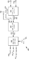
도 3은 본 발명의 다른 실시예에 따라 프리앰블 기반 앵커 로케이션 회로(300)의 단부를 도시하고 있다. 프리앰블 기반 앵커 로케이션 회로(300)는 다수의 데이터 검출 회로에 포함되는 유클리드 메트릭 회로(310)를 재사용한다. 본 분야에 알려져 있는 바와 같이, 유클리드 메트릭 회로(310)는 데이터 입력(305)과 베이스라인(303) 사이의 유클리드 거리를 계산한다. 구체적인 실시예에서, 데이터 입력(305)은 도 1의 멀티플렉서(140)로부터의 데이터 출력(145)이다. 베이스라인(303)이 프리앰블 패턴에 대응하는 경우, 유클리드 출력(325), 즉 Ym[n]는 데이터 입력(305)이 베이스라인(303)과 일치하는 경우에는 비교적 낮은 값에서 인가되며, 유클리드 출력(325)은 데이터 입력(305)이 베이스라인(303)으로부터 벗어나는 경우에는 비교적 높은 값에서 인가된다. 유클리드 출력(325)이 유클리드 값(325)의 증가에 뒤이어 실질적으로 긴 기간(예컨대 14 내지 20 비트 기간) 동안 비교적 낮은 레벨에서 인가되는 경우, 프리앰블의 단부가 표시된다. 정상 조건 하에서, 프리앰블의 이 단부는 오리지널 데이터 동기 마크의 시작을 나타낸다. 그러나, 프리앰블이 본래 기록된 로케이션에 매체 결함이 발생하는 경우, 유클리드 값(325)의 동일한 증가가 발생한다. 따라서, 유클리드 값(325)의 감소가 오리지널 데이터 동기 마크의 검출에 의해 일어나지 않는 경우, 재생가능 결함 검출이 발생했다는 것이 전제로 될 수 있다. 이 재생가능 매체 결함 검출은 도 2와 관련하여 전술한 바와 유사한 강제된 데이터 동기 마크에 기초하여 이용될 수 있는 앵커 지점을 고정시키는 데 이용될 수 있다.3 illustrates an end of a preamble based
유클리드 값(325)은 임계치 테스트 회로(330)로 제공된다. 임계치 테스트 회로(330)는 유클리드 값(325)과 임계치(327)를 비교한다. 유클리드 값(325)기 임계(327)보다 큰 경우, 프리앰블의 단부가 선언된다(즉, 결함 출력(355)인 D[n]이 인가된다). 앵커 지점 생성 회로(360)가 제공된다. 앵커 지점이 놓이는 쿼터 레이트 위상(382)(φ∈{0, 1, 2, 3})도 표시된다. 몇몇 경우, 임계치(327)는 프로그래밍가능하다. 임계치 값(380)은 프리앰블의 단부가 검출되기 전에 임계치(327) 및 유클리드 값(325)의 최대 값을 우선 초과한 유클리드 값(325)을 평균화함으로써 계산될 수 있다.
후속 패스 시(즉, 리트라이 번호(125)가 제 2 또는 그 후의 리트라이를 나타내는 경우), 그것은 반복가능하기 때문에 앵커 지점을 설정하는 동일한 프로세스가 이용될 수 있다. 그러나, 전술한 실시예에 대한 몇몇 경우에 있어서, 후속 리트라이에 대해 임계치(327)는 임계 값(380)이 다시 식별될 때마다 앵커 지점이 나타나도록 임계 값(380)과 동일한 값으로 프로그래밍될 수 있다. 모든 리트라이 패스 시, 앵커 지점에 대한 검색은 제 1 패스 시에 식별된 동일한 쿼터 레이트 위상(382)에서 이루어진다.On subsequent passes (ie, when the retry
임계치(327)는 본래 결함 값을 프로그래밍함으로써 설정될 수 있지만, 모든 리트라이 패스에 따라 동적으로 업데이트될 수 있다. 제 1 패스 시, 프리앰블 단부 검출 지점 이전에 유클리드 값(325)의 최대 값이 레지스터 MAX_VALUE 내에 기록된다. 각각의 후속 리트라이 패스 시, 이 레지스터는 이 패스에 대한 새로운 최대값이 레지스터 MAX_VALUE의 콘텐츠보다 크다면 프리앰블 단부 검출 지점 이전에 새로운 최대 유클리드 값(325)으로 업데이트된다. 현재 패스 시, 유클리드 값(325)이 임계 값(380)보다 크다면, 다음 리트라이에 대한 임계 값(380)은 다음과 같이 설정된다.The
임계 값(380) = (유클리드 값(325)+MAX VALUE)/2Threshold (380) = (Euclidean value (325) + MAX VALUE) / 2
도 2 및 도 3에 예시된 바와 같이 본 발명의 다양한 실시예에 대한 논의에 기초하여, 당업자라면, 도 2 및 도 3에 도시된 앵커 지점 검출 회로가 입력 데이터 내의 매체 결함 부재 시에도 앵커 지점을 성공적으로 검출할 수 있다는 것을 인지할 것이다. 실제 데이터 동기 마크는 도 2의 임계치 테스트 회로(230) 및 도 3의 임계치 테스트 회로(330)가 유효한 앵커 지점으로서 프리앰블 단부의 검출을 인가하게 할 것이다. 이것은 도 2에 이용된 메트리 회로 유클리드에 의해 발생하지만, 실제 동기 마크 위의 2T DFT 값(215)이 2T 프리앰블 패턴 위에서보다 훨씬 작을 것이기 때문에 도 3에서도 발생한다. 따라서, 본 발명은 매체 결함이 발생하든 아니든 앵커 지점의 로케이션에 이용될 수 있다.Based on the discussion of the various embodiments of the present invention as illustrated in FIGS. 2 and 3, those skilled in the art will appreciate that the anchor point detection circuits shown in FIGS. 2 and 3 may provide anchor points even in the absence of media defects in the input data. It will be appreciated that the detection can be successful. The actual data sync mark will cause the
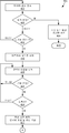
도 4a 및 도 4b를 참조하면, 흐름도(400) 및 흐름도(460)는 본 발명의 하나 이상의 실시예에 따라 앵커 지점을 고정하고 그 앵커 지점에 관련된 데이터 동기 마크를 강제하는 본 발명의 몇몇 실시예에 따른 방법을 도시하고 있다. 흐름도(400)에서, 데이터 샘플이 판독된다(블록 403). 데이터 샘플은 저장 매체로부터 감지된 정보의 디지털 표현일 수 있다. 데이터 샘플은 라이브 데이터 스트림이 이전에 버퍼링되었던 버퍼로부터 또는 라이브 데이터 스트림으로서 판독될 수 있다. 데이터 샘플은 보다 큰 일련의 데이터 샘플에 포함되며, 오리지널 동기 마크가 식별되었는가를 판별하도록 비교된다(블록 406). 오리지널 데이터 동기 마크가 식별되는 경우(블록 406), 처리될 코드워드가 시작되는 경우의 표시로서 오리지널 데이터 동기 마크를 이용하여 오리지널 데이터 동기 마크 다음의 사용자 데이터에 대해 표준 처리가 수행된다(블록 409).4A and 4B,
대안으로, 오리지널 데이터 동기 마크가 발견되지 않는다면(블록 406), 동기 마크가 발견될 것으로 예상된 곳을 넘어 동기 마크에 대한 검색이 이미 확장되었는가가 판정된다(블록 412). 동기 마크가 예상된 영역이 아직 통과되지 않은 경우(블록 412), 오리지널 데이터 동기 마크를 검색하는 프로세스가 계속된다. 한편, 오리지널 데이터 동기 마크가 예상된 영역이 통과된 것으로 판정되는 경우(블록 412), 리트라이 처리가 시작된다(블록 415). 리트라이 처리는 데이터 샘플이 오리지널 처리 중에 저장되었던 버퍼로부터 그 데이터 샘플을 판독하는 단계를 포함한다(블록 418). 이들 샘플은 수신된 데이터를 처리하여 매체 결함이 표시되는가를 판정하는 결함 검출기 회로로 제공된다(블록 421). 결함이 발견되지 않는 경우(블록 421), 데이터 샘플을 판독하고 결함을 검색하는 프로세스가 계속된다. 대안으로, 결함이 발견되면(블록 421), 결함은 그것이 충분히 신뢰할 수 있는지(즉, 단조성을 나타내는지 또는 임계치 테스트를 통과하는지)를 알기 위해 테스트된다(블록 424). 결함이 충분히 신뢰할 수 있는 것으로 발견되지 않는 경우(블록 421), 데이터 샘플을 판독하고 결함 및 신뢰성을 리테스트하는 프로세스가 계속된다. 이와 달리, 결함이 충분히 신뢰할 수 있는 것으로 발견되는 경우(블록 424), 샘플이 발견되었던 앵커 지점(즉, 결함의 로케이션)은 샘플의 위상과 함께 저장되고(블록 427), 임계값이 계산되며 후속 리트라이 패스에 사용하기 위해 저장된다.Alternatively, if the original data sync mark is not found (block 406), it is determined whether the search for the sync mark has already been extended beyond where the sync mark is expected to be found (block 412). If the area where the sync mark was expected has not yet passed (block 412), the process of retrieving the original data sync mark continues. On the other hand, if it is determined that the area where the original data sync mark is expected has passed (block 412), the retry process is started (block 415). The retry process includes reading the data sample from the buffer where the data sample was stored during the original processing (block 418). These samples are provided to a defect detector circuit that processes the received data to determine if a media defect is indicated (block 421). If no defect is found (block 421), the process of reading data samples and searching for defects continues. Alternatively, if a defect is found (block 421), the defect is tested to see if it is reliable enough (i.e. exhibit monotony or pass a threshold test) (block 424). If the defect is not found to be sufficiently reliable (block 421), the process of reading data samples and retesting the defect and reliability continues. Alternatively, if the defect is found to be sufficiently reliable (block 424), the anchor point at which the sample was found (i.e., the location of the defect) is stored with the phase of the sample (block 427), the threshold is calculated and subsequent Stored for use in the retry pass.
흐름도(460)에서, 동기 마크는 이전에 결정된 앵커 지점에 관련되어 초기 로케이션에서 강제된다(즉, 강제된 동기 마크)(블록 463). 몇몇 경우, 이 초기 동기 마크는 앵커 지점과 동일한 로케이션에서 강제된다. 다른 경우, 초기 동기 마크는 앵커 지점으로부터 재생가능 거리만큼 강제될 수 있다. 강제된 동기 마크의 로케이션에 오는 데이터는 그것이 사용자 데이터의 시작부를 나타내는 오리지널 데이터 동기 마크였던 것처럼 강제된 동기 마크를 이용하여 처리된다.(블록 466). 이러한 데이터 처리는, 본 분야에 알려져 있는 바와 같이 저밀도 패리티 체크 디코딩 및/또는 최대 귀납적 데이터 검색을 포함할 수 있지만 이들로 제한되는 것은 아니다. 본 명세서에서 제공된 교시에 기초하여, 당업자라면 판독 데이터에 적용될 수 있는 다양한 데이터 처리 방안을 인지할 것이다.In
데이터 처리가 수렴했는지(즉, 예상 결과를 제공했는지)가 판정된다(블록 469). 데이터 처리가 수렴한 경우(블록 469), 강제된 동기 마크는 오리지널 데이터 동기 마크의 로케이션에 있는 것으로 가정되고 대응하는 매체 영역으로의 추후 액세스에 대한 재사용을 위해 저장된다(블록 472). 그와 달리, 데이터 처리가 수렴하는 데 실패한 경우(블록 469), 식별된 앵커 지점에 관련된 로케이션은 증가하고(블록 475), 동기 마크는 새로이 증가하는 로케이션에서 강제된다(블록 478). 동기 마크를 강제하는 이 프로세스는 타임아웃 조건이 충족되거나 데이터 처리가 수집될 때까지 계속된다(블록 469).It is determined whether the data processing converged (ie, provided the expected result) (block 469). If data processing has converged (block 469), the forced sync mark is assumed to be at the location of the original data sync mark and stored for reuse for later access to the corresponding media area (block 472). In contrast, if data processing fails to converge (block 469), the location associated with the identified anchor point is increased (block 475), and the sync mark is forced at the newly increasing location (block 478). This process of forcing a sync mark continues until a timeout condition is met or data processing is collected (block 469).
도 5를 참조하면, 앵커 지점 회로 및 동기 마크 강제 회로와 함께 판독 채널(510)을 포함하는 저장 시스템(500)이 본 발명의 다양한 실시예에 따라 도시된다. 저장 시스템(500)은, 예를 들어 하드디스크 드라이브일 수 있다. 저장 시스템(500)은 또한 전치증폭기(570), 인터페이스 제어기(520), 하드디스크 제어기(566), 모터 제어기(568), 스핀들 모터(572), 디스크 플래터(578), 및 판독/기록 헤드(576)를 포함한다. 인터페이스 제어기(520)는 디스크 플래터(578)로의/로부터의 데이터 어드레싱 및 타이밍을 제어한다. 디스크 플래터(578) 상의 데이터는 어셈블리가 디스크 플래터(578) 위에 적절히 배치될 때 판독/기록 헤드 어셈블리(576)에 의해 검출될 수 있는 자기 신호 그룹으로 이루어진다. 일 실시예에서, 디스크 플래터(578)는 특정 기록 방식에 따라 기록되는 자기 신호를 포함한다.Referring to FIG. 5, a
일반적인 판독 동작 시, 기록/판독 헤드 어셈블리(576)는 디스크 플래터(578) 상의 희망 데이터 트랙 위에 모터 제어기(568)에 의해 정교하게 배치된다. 모터 제어기(568)는 디스크 플래터(578)와 관련하여 판독/기록 헤드 어셈블리(576)를 배치하고, 하드디스크 제어기(566)의 지시 하에 디스크 플래터(578) 상의 적절한 데이터 트랙으로 판독/기록 헤드 어셈블리를 이동시킴으로써 스핀들 모터(572)를 구동한다. 스핀들 모터(572)는 사전결정된 스핀 레이트(RPM)에서 디스크 플래터(578)를 스핀시킨다. 일단 판독/기록 헤드 어셈블리(578)가 적절한 데이터 트랙에 인접하게 배치되면, 디스크 플래터(578)가 스핀들 모터(572)에 의해 회전될 때 디스크 플래터(578) 상의 데이터를 나타내는 자기적 신호가 판독/기록 헤드 어셈블리(576)에 의해 감지된다. 감지된 자기적 신호는 디스크 플래터(578) 상의 자기적 데이터를 표현하는 계속적이고 순간적인 아날로그 신호로서 제공된다. 이 순간적인 아날로그 신호는 사전증폭기(570)를 통해 판독/기록 헤드 어셈블리(576)로부터 판독 채널 모듈(510)을 통해 전달된다. 사전증폭기(570)는 디스크 플래터(578)로부터 액세스되는 순간적 아날로그 신호를 증폭하도록 동작가능하다. 역시, 판독 채널 모듈(510)은 수신된 아날로그 신호를 디코딩하고 디지털화하여, 디스크 플래터(578)에 본래 기록된 정보를 작성한다. 이 데이터는 판독 데이터(503}로서 수신 회로로 제공된다. 기록 동작은 판독 채널 모듈(510)에 제공되는 기록 데이터(501)와 함께 선행하는 판독 동작의 실질적으로 반대편에 있다. 이 데이터는 디스크 플래터(578)로 인코딩되고 기록된다. In a typical read operation, the write /
앵커 지점 회로 및 동기 마크 강제 회로는 도 1 내지 도 3과 관련된 것들과 유사할 수 있으며, 및/또는 도 4a 및 도 4b와 관련하여 위에서 논의된 것과는 동작할 수 있습니다. 이러한 앵커 지점 회로 및 동기 마크 강제 회로는 매체 상의 재생가능 로케이션을 식별하고 본 명세서에서 설명한 바와 같이 재생가능 로케이션에 관련된 동기 마크를 강제할 수 있다.The anchor point circuit and the sync mark forced circuit may be similar to those associated with FIGS. 1-3 and / or may operate with those discussed above with respect to FIGS. 4A and 4B. Such anchor point circuitry and sync mark forcing circuitry may identify a reproducible location on the medium and force a sync mark associated with the reproducible location as described herein.
결론적으로, 본 발명은 저장 매체 상의 재생가능 로케이션을 식별하는 신규한 시스템, 방법 및 장치를 제공한다. 본 발명의 하나 이상의 실시예에 대한 상세한 설명이 위에 주어져 있기는 하지만, 본 발명의 사상으로부터 변화하지 않고도 다양한 대안, 수정 및 등가물이 당업자에게는 명백할 것이다. 따라서, 전술한 설명은 첨부한 특허청구범위에 의해 정의되는 본 발명의 범주를 제한하는 것으로 간주되어서는 안 된다.In conclusion, the present invention provides a novel system, method and apparatus for identifying a reproducible location on a storage medium. While a detailed description of one or more embodiments of the invention has been given above, various alternatives, modifications, and equivalents will be apparent to those skilled in the art without changing from the spirit of the invention. Accordingly, the foregoing description should not be taken as limiting the scope of the invention as defined by the appended claims.
Claims (21)
매체 결함을 식별하도록 동작가능한 매체 결함 검출기와,
상기 매체 결함에 관련된 재생가능한 로케이션을 식별하도록 동작가능한 앵커 고정 회로를 포함하는
재생가능 로케이션 식별 회로.
A circuit for identifying a reproducible location on a storage medium, the circuit comprising:
A media defect detector operable to identify a media defect,
And anchor anchor circuitry operable to identify a reproducible location associated with the media defect.
Renewable location identification circuit.
상기 매체 결함 검출기는 이산 푸리에 변환 회로를 포함하는
재생가능 로케이션 식별 회로.
The method of claim 1,
The medium defect detector includes a discrete Fourier transform circuit.
Renewable location identification circuit.
상기 이산 푸리에 변환 회로는 2T 패턴으로 튜닝되는
재생가능 로케이션 식별 회로.
The method of claim 2,
The discrete Fourier transform circuit is tuned to a 2T pattern
Renewable location identification circuit.
상기 매체 결함 검출기는 저장 매체로부터 유도되는 일련의 데이터 샘플을 이용하여 매체 결함을 식별하도록 동작가능하되,
상기 회로는,
상기 로케이션으로부터의 고정 거리인 강제된 데이터 동기 마크를 이용하여 상기 일련의 데이터 샘플의 서브세트를 처리하도록 동작가능한 데이터 처리 회로를 더 포함하는
재생가능 로케이션 식별 회로.
The method of claim 1,
The medium defect detector is operable to identify a medium defect using a series of data samples derived from a storage medium,
The circuit is,
Further comprising data processing circuitry operable to process said subset of said series of data samples using a forced data sync mark that is a fixed distance from said location;
Renewable location identification circuit.
상기 회로는,
상기 데이터 처리 회로가 수렴하지 못하는 경우에는 강제된 데이터 동기 마크를 반복해서 식별하고, 상기 데이터 처리 회로가 수렴하는 경우에는 상기 강제된 데이터 동기 마크를 저장하도록 동작가능한 동기 강제 회로를 더 포함하는
재생가능 로케이션 식별 회로.
The method of claim 4, wherein
The circuit is,
Further comprising a synchronous forcing circuit operable to repeatedly identify the forced data sync mark if the data processing circuit fails to converge, and to store the forced data sync mark if the data processing circuit converges;
Renewable location identification circuit.
상기 회로는,
상기 저장 매체 상의 디코딩가능 데이터 세트의 시작부를 나타내도록 상기 저장 매체로부터의 후속 판독 시에 이용가능한 상기 강제된 데이터 동기 마크를 저장하는 데이터 버퍼를 더 포함하는
재생가능 로케이션 식별 회로.
The method of claim 5, wherein
The circuit is,
And a data buffer for storing the forced data sync mark available upon subsequent reading from the storage medium to indicate the beginning of the decodable data set on the storage medium.
Renewable location identification circuit.
상기 매체 결함 검출기는 프리앰블 검출기 회로의 단부를 포함하는
재생가능 로케이션 식별 회로.
The method of claim 1,
The media fault detector includes an end of the preamble detector circuit.
Renewable location identification circuit.
저장 매체로부터 유도되는 일련의 데이터 샘플을 수신하는 단계와,
상기 일련의 데이터 샘플을 이용하여 상기 저장 매체 상의 매체 결함을 식별하는 단계와,
상기 매체 결함에 관련된 상기 저장 매체 상에 재생가능한 로케이션을 고정하는 단계를 포함하는
재생가능 로케이션 식별 방법.
A method of identifying a playable location on a storage medium, the method comprising:
Receiving a series of data samples derived from a storage medium;
Identifying a media defect on the storage medium using the series of data samples;
Fixing a reproducible location on the storage medium associated with the media defect.
Replay Location Identification Method.
상기 방법은,
디코딩가능 데이터 세트의 시작부에 대한 기준으로서 상기 로케이션을 이용하여 상기 일련의 데이터 샘플의 서브세트에 디코딩 알고리즘을 적용하는 단계를 더 포함하는
재생가능 로케이션 식별 방법.
The method of claim 8,
The method comprises:
Applying a decoding algorithm to the subset of the series of data samples using the location as a reference to the beginning of a decodable data set.
Replay Location Identification Method.
상기 디코딩 알고리즘은 수렴하고,
상기 방법은,
메모리에 강제된 데이터 동기 마크를 저장하는 단계를 더 포함하되,
상기 강제된 데이터 동기 마크는 상기 로케이션을 나타내고, 상기 저장 매체로부터의 후속 판독 시에 상기 저장 매체 상의 디코딩가능 데이터 세트의 시작부를 나타내도록 이용가능한
재생가능 로케이션 식별 방법.
The method of claim 9,
The decoding algorithm converges,
The method comprises:
Storing the forced data sync mark in memory,
The forced data sync mark indicates the location and is available to indicate the beginning of a decodable data set on the storage medium upon subsequent reading from the storage medium.
Replay Location Identification Method.
상기 로케이션은 제 1 로케이션이고,
상기 방법은,
디코딩가능 데이터 세트의 시작부에 대한 기준으로서 상기 제 1 로케이션을 이용하여 상기 일련의 데이터 샘플의 제 1 서브세트에 디코딩 알고리즘을 적용하는 단계―여기서, 상기 디코딩 알고리즘은 수렴하지 않음―와,
상기 매체 결함에 관련된 상기 저장 매체 상에 재생가능한 제 2 로케이션을 고정하는 단계와,
상기 디코딩가능 데이터 세트의 시작부에 대한 기준으로서 상기 제 2 로케이션을 이용하여 상기 일련의 데이터 샘플의 제 2 서브세트에 상기 디코딩 알고리즘을 적용하는 단계를 더 포함하는
재생가능 로케이션 식별 방법.
The method of claim 8,
The location is a first location,
The method comprises:
Applying a decoding algorithm to the first subset of the series of data samples using the first location as a reference to the beginning of a decodable data set, wherein the decoding algorithm does not converge;
Fixing a reproducible second location on the storage medium associated with the medium defect;
Applying the decoding algorithm to the second subset of the series of data samples using the second location as a reference to the beginning of the decodable data set.
Replay Location Identification Method.
상기 제 2 로케이션을 이용한 상기 디코딩 알고리즘의 적용이 수렴하고,
상기 방법은,
강제된 데이터 동기 마크를 메모리에 저장하는 단계를 더 포함하되,
상기 강제된 데이터 동기 마크는 상기 제 2 로케이션을 나타내고, 상기 저장 매체 상의 상기 디코딩가능 데이터 세트의 시작부를 나타내도록 상기 저장 매체로부터의 후속 판독 시에 이용가능한
재생가능 로케이션 식별 방법.
The method of claim 11,
Application of the decoding algorithm using the second location converges,
The method comprises:
Storing the forced data sync mark in memory,
The forced data sync mark indicates the second location and is available upon subsequent reading from the storage medium to indicate the beginning of the decodable data set on the storage medium.
Replay Location Identification Method.
상기 제 2 로케이션은 상기 제 1 로케이션보다 상기 매체 결함으로부터 더 멀리 있는
재생가능 로케이션 식별 방법.
The method of claim 11,
The second location is further from the media fault than the first location
Replay Location Identification Method.
상기 디코딩 알고리즘은 저밀도 패리티 체크 알고리즘인
재생가능 로케이션 식별 방법.
The method of claim 11,
The decoding algorithm is a low density parity check algorithm
Replay Location Identification Method.
저장 매체로부터 유도되는 일련의 데이터 샘플을 수신하는 단계는 데이터 버퍼로부터 상기 일련의 데이터 샘플을 액세스하는 단계를 포함하는
재생가능 로케이션 식별 방법.
The method of claim 8,
Receiving a series of data samples derived from a storage medium includes accessing the series of data samples from a data buffer.
Replay Location Identification Method.
상기 방법은,
상기 저장 매체로부터 정보를 액세스하는 단계와,
상기 정보에 기초하여 상기 일련의 데이터 샘플을 생성하는 단계를 더 포함하는
재생가능 로케이션 식별 방법.
The method of claim 8,
The method comprises:
Accessing information from the storage medium;
Generating the series of data samples based on the information.
Replay Location Identification Method.
저장 매체와,
상기 저장 매체로부터 유도되는 일련의 데이터 샘플을 이용하여 상기 저장 매체 상의 매체 결함을 식별하도록 동작가능한 매체 결함 검출기와,
상기 매체 결함과 관련된 재생가능한 로케이션을 식별하도록 동작가능한 앵커 고정 회로를 포함하는
하드디스크 드라이브 시스템.
As a hard disk drive system,
Storage media,
A media defect detector operable to identify a media defect on said storage medium using a series of data samples derived from said storage medium;
Anchor anchor circuitry operable to identify a reproducible location associated with the media defect;
Hard disk drive system.
상기 매체 결함 검출기는, 이산 푸리에 변환 회로 및 프리앰블 검출기 회로의 단부로 이루어진 그룹으로부터 선택되는 회로를 포함하는
하드디스크 드라이브 시스템.
The method of claim 17,
The medium defect detector includes a circuit selected from the group consisting of discrete Fourier transform circuits and ends of the preamble detector circuits.
Hard disk drive system.
상기 시스템은,
상기 로케이션으로부터의 고정 거리인 강제된 데이터 동기 마크를 이용하여 상기 일련의 데이터 샘플의 서브세트를 처리하도록 동작가능한 데이터 처리 회로를 더 포함하는
하드디스크 드라이브 시스템.
The method of claim 17,
The system,
Further comprising data processing circuitry operable to process said subset of said series of data samples using a forced data sync mark that is a fixed distance from said location;
Hard disk drive system.
상기 시스템은,
상기 데이터 처리 회로가 수렴하지 못하는 경우에는 강제된 데이터 동기 마크를 반복해서 식별하고, 상기 데이터 처리 회로가 수렴하는 경우에는 상기 강제된 데이터 동기 마크를 저장하도록 동작가능한 동기 강제 회로를 더 포함하는
하드디스크 드라이브 시스템.
The method of claim 19,
The system,
Further comprising a synchronous forcing circuit operable to repeatedly identify the forced data sync mark if the data processing circuit fails to converge, and to store the forced data sync mark if the data processing circuit converges;
Hard disk drive system.
상기 시스템은,
상기 저장 매체 상의 디코딩가능 데이터 세트의 시작부를 나타내도록 상기 저장 매체로부터의 후속 판독 시에 이용가능한 상기 강제된 데이터 동기 마크를 저장하는 데이터 버퍼를 더 포함하는
하드디스크 드라이브 시스템.The method of claim 20,
The system,
And a data buffer for storing the forced data sync mark available upon subsequent reading from the storage medium to indicate the beginning of the decodable data set on the storage medium.
Hard disk drive system.
Applications Claiming Priority (2)
| Application Number | Priority Date | Filing Date | Title |
|---|---|---|---|
| US12/712,136 US20110205653A1 (en) | 2010-02-24 | 2010-02-24 | Systems and Methods for Data Recovery |
| US12/712,136 | 2010-02-24 |
Publications (1)
| Publication Number | Publication Date |
|---|---|
| KR20110097575A true KR20110097575A (en) | 2011-08-31 |
Family
ID=42830660
Family Applications (1)
| Application Number | Title | Priority Date | Filing Date |
|---|---|---|---|
| KR1020100065520A KR20110097575A (en) | 2010-02-24 | 2010-07-07 | Systems and methods for data recovery |
Country Status (6)
| Country | Link |
|---|---|
| US (1) | US20110205653A1 (en) |
| EP (1) | EP2360696A1 (en) |
| JP (1) | JP2011175721A (en) |
| KR (1) | KR20110097575A (en) |
| CN (1) | CN102163464A (en) |
| TW (1) | TW201137865A (en) |
Families Citing this family (16)
| Publication number | Priority date | Publication date | Assignee | Title |
|---|---|---|---|---|
| US8949701B2 (en) | 2008-09-23 | 2015-02-03 | Agere Systems Inc. | Systems and methods for low latency media defect detection |
| US8631300B2 (en) * | 2011-12-12 | 2014-01-14 | Lsi Corporation | Systems and methods for scalable data processing shut down |
| US9129653B2 (en) | 2012-04-20 | 2015-09-08 | Avago Technologies General Ip (Singapore) Pte. Ltd. | Systems and methods for calibration coasting in a data processing system |
| US8819521B2 (en) | 2012-04-30 | 2014-08-26 | Lsi Corporation | Systems and methods for short media defect detection using non-binary coded information |
| US8675297B2 (en) | 2012-06-15 | 2014-03-18 | Lsi Corporation | Media defect classification |
| US9076492B2 (en) | 2012-07-12 | 2015-07-07 | Lsi Corporation | Systems and methods for rapid erasure retry decoding |
| US8826110B2 (en) | 2012-07-17 | 2014-09-02 | Lsi Corporation | Systems and methods for defect scanning |
| US8732562B2 (en) | 2012-07-25 | 2014-05-20 | Lsi Corporation | Systems and methods for improved short media defect detection |
| US8972800B2 (en) * | 2012-07-30 | 2015-03-03 | Lsi Corporation | Systems and methods for enhanced media defect detection |
| US9245586B2 (en) | 2012-10-18 | 2016-01-26 | Avago Technologies General Ip (Singapore) Pte. Ltd. | Systems and methods for short media defect detection using multi-iteration soft data feedback |
| US8996970B2 (en) | 2012-10-24 | 2015-03-31 | Lsi Corporation | Systems and methods for positive feedback short media defect detection |
| US8687301B1 (en) * | 2013-01-08 | 2014-04-01 | Lsi Corporation | Parallel no-sync-mark retry |
| US9244752B2 (en) | 2013-05-02 | 2016-01-26 | Avago Technologies General Ip (Singapore) Pte. Ltd. | Systems and methods for detecting media flaws |
| US8917468B1 (en) | 2013-06-06 | 2014-12-23 | Lsi Corporation | Systems and methods for media defect detection with pattern qualification |
| US9804919B2 (en) | 2015-07-20 | 2017-10-31 | Avago Technologies General Ip (Singapore) Pte. Ltd. | Systems and methods for correlation based data alignment |
| JP2018160302A (en) | 2017-03-23 | 2018-10-11 | 株式会社東芝 | Storage device and controller |
Family Cites Families (46)
| Publication number | Priority date | Publication date | Assignee | Title |
|---|---|---|---|---|
| JPH02192076A (en) * | 1989-01-19 | 1990-07-27 | Nec Corp | Phase pull-in control circuit |
| US5416760A (en) * | 1991-12-16 | 1995-05-16 | Advanced Micro Devices, Inc. | Recovery of data from optical data disk sectors having missing or defective synchronization information |
| US5802069A (en) * | 1995-11-13 | 1998-09-01 | Intel Corporation | Implementing mass storage device functions using host processor memory |
| JP3310185B2 (en) * | 1996-11-21 | 2002-07-29 | 松下電器産業株式会社 | Error correction device |
| KR100258332B1 (en) * | 1997-12-26 | 2000-06-01 | 윤종용 | Sync. detector and optical disc reproducer thereby |
| JP4173931B2 (en) * | 1998-10-16 | 2008-10-29 | 富士通株式会社 | Magnetic disk drive and data reading method used therefor |
| US6557113B1 (en) * | 1999-10-26 | 2003-04-29 | Iomega Corporation | Synchronization recovery technique for storage media |
| KR20020041012A (en) * | 1999-10-28 | 2002-05-31 | 추후 | Sync byte padding |
| WO2002009109A1 (en) * | 2000-07-21 | 2002-01-31 | Fujitsu Limited | Disk recording device, sector alternating method for recording disk, and recording disk |
| US6738948B2 (en) * | 2001-04-09 | 2004-05-18 | Motorola, Inc. | Iteration terminating using quality index criteria of turbo codes |
| US6691263B2 (en) * | 2001-05-03 | 2004-02-10 | Agere Systems Inc. | Interative decoding based on dominant error events |
| JP4198904B2 (en) * | 2001-06-11 | 2008-12-17 | 富士通株式会社 | Recording / reproducing apparatus, signal decoding circuit, error correcting method, and iterative decoder |
| US7440208B1 (en) * | 2001-09-21 | 2008-10-21 | Maxtor Corporation | Flexible partial response targets for data detectors |
| US6731442B2 (en) * | 2001-10-02 | 2004-05-04 | Seagate Technologies Llc | Method and apparatus for detecting media defects |
| JP3759711B2 (en) * | 2001-11-09 | 2006-03-29 | 富士通株式会社 | Magnetic disk system |
| US7154936B2 (en) * | 2001-12-03 | 2006-12-26 | Qualcomm, Incorporated | Iterative detection and decoding for a MIMO-OFDM system |
| JP4017883B2 (en) * | 2002-02-20 | 2007-12-05 | 株式会社日立グローバルストレージテクノロジーズ | Defect detection method, defect detection apparatus, information recording / reproducing apparatus, and magnetic disk apparatus |
| US7359313B2 (en) * | 2002-06-24 | 2008-04-15 | Agere Systems Inc. | Space-time bit-interleaved coded modulation for wideband transmission |
| US7254192B2 (en) * | 2002-07-12 | 2007-08-07 | Texas Instruments Incorporated | Iterative detection in MIMO systems |
| JP3749889B2 (en) * | 2002-10-17 | 2006-03-01 | 株式会社東芝 | Signal processing device to which PRML detection is applied, disk storage device having the device, and signal processing method for feedback control in the device |
| US7277368B2 (en) * | 2002-11-11 | 2007-10-02 | Matsushita Electric Industrial Co., Ltd. | Playback method, playback control circuit and playback apparatus for a recording medium |
| JP4006446B2 (en) * | 2002-12-10 | 2007-11-14 | 富士通株式会社 | Data recording / playback system |
| WO2004097812A1 (en) * | 2003-04-30 | 2004-11-11 | Ricoh Company, Ltd. | Information recording method and device, information reproduction method and device, and recording medium |
| JP4499372B2 (en) * | 2003-04-30 | 2010-07-07 | 株式会社リコー | Information recording method, information reproducing method, information recording apparatus, information reproducing apparatus, and computer-readable recording medium |
| JP4095504B2 (en) * | 2003-07-31 | 2008-06-04 | 株式会社東芝 | Disk storage device and sync mark writing method |
| US7168030B2 (en) * | 2003-10-17 | 2007-01-23 | Telefonaktiebolaget Lm Ericsson (Publ) | Turbo code decoder with parity information update |
| EP1605597A1 (en) * | 2004-06-03 | 2005-12-14 | STMicroelectronics N.V. | Method and system for blindly detecting a shared channel out of a plurality of shared channels received in parallel |
| KR20070025145A (en) * | 2005-08-31 | 2007-03-08 | 삼성전자주식회사 | Soft decoding method and apparatus therefore and error correction method and apparatus therefore, soft output method and apparatus therefore |
| US7441174B2 (en) * | 2005-09-07 | 2008-10-21 | The University Of Hong Kong | Embedded state metric storage for MAP decoder of turbo codes |
| US7752523B1 (en) * | 2006-02-13 | 2010-07-06 | Marvell International Ltd. | Reduced-complexity decoding of parity check codes |
| FR2909499B1 (en) * | 2006-12-01 | 2009-01-16 | Commissariat Energie Atomique | METHOD AND DEVICE FOR DECODING LDPC CODES, AND COMMUNICATION APPARATUS COMPRISING SUCH A DEVICE |
| US7702973B2 (en) * | 2007-01-05 | 2010-04-20 | Broadcom Corporation | Modified defect scan over sync mark/preamble field |
| US20080262643A1 (en) * | 2007-04-17 | 2008-10-23 | Broadcom Corporation, A California Corporation | Defect detector for hard disk drive and methods for use therewith |
| US8359522B2 (en) * | 2007-05-01 | 2013-01-22 | Texas A&M University System | Low density parity check decoder for regular LDPC codes |
| WO2009045203A1 (en) * | 2007-10-01 | 2009-04-09 | Agere Systems Inc. | Systems and methods for media defect detection |
| US8095855B2 (en) * | 2008-03-17 | 2012-01-10 | Agere Systems Inc. | Systems and methods for regenerating data from a defective medium |
| US8161357B2 (en) * | 2008-03-17 | 2012-04-17 | Agere Systems Inc. | Systems and methods for using intrinsic data for regenerating data from a defective medium |
| US8121224B2 (en) * | 2008-04-29 | 2012-02-21 | Agere Systems Inc. | Systems and methods for filter based media defect detection |
| US8149527B2 (en) * | 2008-04-29 | 2012-04-03 | Agere Systems Inc. | Systems and methods for reducing attenuation of information derived from a defective medium |
| US7849385B2 (en) * | 2008-04-29 | 2010-12-07 | Agere Systems Inc. | Systems and methods for media defect detection utilizing correlated DFIR and LLR data |
| US8139457B2 (en) * | 2008-09-23 | 2012-03-20 | Agere Systems Inc. | Systems and methods for low latency media defect detection |
| US8190831B2 (en) * | 2008-10-31 | 2012-05-29 | Lsi Corporation | Methods and apparatus for detecting a syncMark in a hard disk drive |
| US8411537B2 (en) * | 2009-03-06 | 2013-04-02 | Agere Systems Inc. | Systems and methods for recovering information from a defective medium |
| US8219892B2 (en) * | 2009-03-06 | 2012-07-10 | Agere Systems Inc. | Systems and methods for enhanced media defect detection |
| US7952824B2 (en) * | 2009-03-06 | 2011-05-31 | Agere Systems Inc. | Systems and methods for defective media region identification |
| JP4724241B2 (en) * | 2009-07-09 | 2011-07-13 | 株式会社東芝 | Disk storage device and data detection method |
-
2010
- 2010-02-24 US US12/712,136 patent/US20110205653A1/en not_active Abandoned
- 2010-07-05 TW TW099122006A patent/TW201137865A/en unknown
- 2010-07-07 KR KR1020100065520A patent/KR20110097575A/en not_active Application Discontinuation
- 2010-07-30 EP EP10251369A patent/EP2360696A1/en not_active Withdrawn
- 2010-11-17 CN CN2010105474701A patent/CN102163464A/en active Pending
- 2010-11-18 JP JP2010257420A patent/JP2011175721A/en active Pending
Also Published As
| Publication number | Publication date |
|---|---|
| TW201137865A (en) | 2011-11-01 |
| US20110205653A1 (en) | 2011-08-25 |
| CN102163464A (en) | 2011-08-24 |
| JP2011175721A (en) | 2011-09-08 |
| EP2360696A1 (en) | 2011-08-24 |
Similar Documents
| Publication | Publication Date | Title |
|---|---|---|
| KR20110097575A (en) | Systems and methods for data recovery | |
| US8345369B2 (en) | Systems and methods for data recovery using enhanced sync mark location | |
| KR101489549B1 (en) | Methods and apparatus for detecting a syncmark in a hard disk drive | |
| US7733591B2 (en) | Data storage device with data recovery process using fixed phase clocking for analog-to-digital conversion | |
| US6937415B2 (en) | Method and apparatus for enhanced data channel performance using read sample buffering | |
| KR100959306B1 (en) | System and method for searching for duplicate data | |
| KR100717102B1 (en) | Bca data replay | |
| US7032127B1 (en) | Method and apparatus for identifying defective areas on a disk surface of a disk drive based on defect density | |
| EP0164746A2 (en) | Optical information recording and reproducing apparatus and optical disc | |
| US7171607B2 (en) | Apparatus and method for verifying erasure correction function | |
| US7817363B2 (en) | Single-pass defect detection for hard-disk drive systems | |
| JP2007141305A (en) | Magnetic disk drive | |
| US8908307B1 (en) | Systems and methods for hard disk drive region based data encoding | |
| US5737145A (en) | Method for generating index pulse with index pattern | |
| US6671114B2 (en) | Method and apparatus for forming data sector suitable for high density hard disk drive | |
| US7120100B2 (en) | Method for preventing an optical recording device from erroneous defect detecting during writing | |
| US20020023248A1 (en) | Medium defect detection method and data storage apparatus | |
| US6976196B2 (en) | Error detecting method and device, information storing and reproducing device and magnetic disk drive | |
| US9042045B1 (en) | Disk drive adjusting a defect threshold when scanning for defective sectors | |
| JP2004005850A (en) | Method and system for detecting defect of recording medium | |
| JP2589673B2 (en) | Address data detection device | |
| US8874410B2 (en) | Systems and methods for pattern detection | |
| US9536562B1 (en) | Method and apparatus for imitating a defect in a read-back signal received from a rotating storage medium | |
| KR100518515B1 (en) | How to Detect Hard Disk Defects | |
| JP2001273719A (en) | Method and system for detecting medium defect and information recording and reproducing device using them |
Legal Events
| Date | Code | Title | Description |
|---|---|---|---|
| WITN | Application deemed withdrawn, e.g. because no request for examination was filed or no examination fee was paid |