KR20110082543A - Board cable connection structure - Google Patents
Board cable connection structure Download PDFInfo
- Publication number
- KR20110082543A KR20110082543A KR1020117010234A KR20117010234A KR20110082543A KR 20110082543 A KR20110082543 A KR 20110082543A KR 1020117010234 A KR1020117010234 A KR 1020117010234A KR 20117010234 A KR20117010234 A KR 20117010234A KR 20110082543 A KR20110082543 A KR 20110082543A
- Authority
- KR
- South Korea
- Prior art keywords
- circuit board
- relay connector
- cable
- connection structure
- cables
- Prior art date
Links
Images


Classifications
-
- H—ELECTRICITY
- H01—ELECTRIC ELEMENTS
- H01R—ELECTRICALLY-CONDUCTIVE CONNECTIONS; STRUCTURAL ASSOCIATIONS OF A PLURALITY OF MUTUALLY-INSULATED ELECTRICAL CONNECTING ELEMENTS; COUPLING DEVICES; CURRENT COLLECTORS
- H01R12/00—Structural associations of a plurality of mutually-insulated electrical connecting elements, specially adapted for printed circuits, e.g. printed circuit boards [PCB], flat or ribbon cables, or like generally planar structures, e.g. terminal strips, terminal blocks; Coupling devices specially adapted for printed circuits, flat or ribbon cables, or like generally planar structures; Terminals specially adapted for contact with, or insertion into, printed circuits, flat or ribbon cables, or like generally planar structures
- H01R12/50—Fixed connections
- H01R12/59—Fixed connections for flexible printed circuits, flat or ribbon cables or like structures
- H01R12/62—Fixed connections for flexible printed circuits, flat or ribbon cables or like structures connecting to rigid printed circuits or like structures
-
- H—ELECTRICITY
- H01—ELECTRIC ELEMENTS
- H01R—ELECTRICALLY-CONDUCTIVE CONNECTIONS; STRUCTURAL ASSOCIATIONS OF A PLURALITY OF MUTUALLY-INSULATED ELECTRICAL CONNECTING ELEMENTS; COUPLING DEVICES; CURRENT COLLECTORS
- H01R12/00—Structural associations of a plurality of mutually-insulated electrical connecting elements, specially adapted for printed circuits, e.g. printed circuit boards [PCB], flat or ribbon cables, or like generally planar structures, e.g. terminal strips, terminal blocks; Coupling devices specially adapted for printed circuits, flat or ribbon cables, or like generally planar structures; Terminals specially adapted for contact with, or insertion into, printed circuits, flat or ribbon cables, or like generally planar structures
- H01R12/70—Coupling devices
- H01R12/77—Coupling devices for flexible printed circuits, flat or ribbon cables or like structures
-
- H—ELECTRICITY
- H01—ELECTRIC ELEMENTS
- H01R—ELECTRICALLY-CONDUCTIVE CONNECTIONS; STRUCTURAL ASSOCIATIONS OF A PLURALITY OF MUTUALLY-INSULATED ELECTRICAL CONNECTING ELEMENTS; COUPLING DEVICES; CURRENT COLLECTORS
- H01R12/00—Structural associations of a plurality of mutually-insulated electrical connecting elements, specially adapted for printed circuits, e.g. printed circuit boards [PCB], flat or ribbon cables, or like generally planar structures, e.g. terminal strips, terminal blocks; Coupling devices specially adapted for printed circuits, flat or ribbon cables, or like generally planar structures; Terminals specially adapted for contact with, or insertion into, printed circuits, flat or ribbon cables, or like generally planar structures
- H01R12/50—Fixed connections
- H01R12/59—Fixed connections for flexible printed circuits, flat or ribbon cables or like structures
- H01R12/65—Fixed connections for flexible printed circuits, flat or ribbon cables or like structures characterised by the terminal
-
- H—ELECTRICITY
- H01—ELECTRIC ELEMENTS
- H01R—ELECTRICALLY-CONDUCTIVE CONNECTIONS; STRUCTURAL ASSOCIATIONS OF A PLURALITY OF MUTUALLY-INSULATED ELECTRICAL CONNECTING ELEMENTS; COUPLING DEVICES; CURRENT COLLECTORS
- H01R12/00—Structural associations of a plurality of mutually-insulated electrical connecting elements, specially adapted for printed circuits, e.g. printed circuit boards [PCB], flat or ribbon cables, or like generally planar structures, e.g. terminal strips, terminal blocks; Coupling devices specially adapted for printed circuits, flat or ribbon cables, or like generally planar structures; Terminals specially adapted for contact with, or insertion into, printed circuits, flat or ribbon cables, or like generally planar structures
- H01R12/70—Coupling devices
- H01R12/7005—Guiding, mounting, polarizing or locking means; Extractors
- H01R12/7011—Locking or fixing a connector to a PCB
-
- H—ELECTRICITY
- H01—ELECTRIC ELEMENTS
- H01R—ELECTRICALLY-CONDUCTIVE CONNECTIONS; STRUCTURAL ASSOCIATIONS OF A PLURALITY OF MUTUALLY-INSULATED ELECTRICAL CONNECTING ELEMENTS; COUPLING DEVICES; CURRENT COLLECTORS
- H01R12/00—Structural associations of a plurality of mutually-insulated electrical connecting elements, specially adapted for printed circuits, e.g. printed circuit boards [PCB], flat or ribbon cables, or like generally planar structures, e.g. terminal strips, terminal blocks; Coupling devices specially adapted for printed circuits, flat or ribbon cables, or like generally planar structures; Terminals specially adapted for contact with, or insertion into, printed circuits, flat or ribbon cables, or like generally planar structures
- H01R12/70—Coupling devices
- H01R12/77—Coupling devices for flexible printed circuits, flat or ribbon cables or like structures
- H01R12/79—Coupling devices for flexible printed circuits, flat or ribbon cables or like structures connecting to rigid printed circuits or like structures
-
- H—ELECTRICITY
- H01—ELECTRIC ELEMENTS
- H01R—ELECTRICALLY-CONDUCTIVE CONNECTIONS; STRUCTURAL ASSOCIATIONS OF A PLURALITY OF MUTUALLY-INSULATED ELECTRICAL CONNECTING ELEMENTS; COUPLING DEVICES; CURRENT COLLECTORS
- H01R12/00—Structural associations of a plurality of mutually-insulated electrical connecting elements, specially adapted for printed circuits, e.g. printed circuit boards [PCB], flat or ribbon cables, or like generally planar structures, e.g. terminal strips, terminal blocks; Coupling devices specially adapted for printed circuits, flat or ribbon cables, or like generally planar structures; Terminals specially adapted for contact with, or insertion into, printed circuits, flat or ribbon cables, or like generally planar structures
- H01R12/70—Coupling devices
- H01R12/77—Coupling devices for flexible printed circuits, flat or ribbon cables or like structures
- H01R12/771—Details
- H01R12/775—Ground or shield arrangements
Abstract
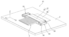
케이블과 회로 기판의 전기적 접속의 신뢰성을 손상시키지 않고도 케이블과 회로 기판의 접속부의 크기 및 높이를 감소시킬 수 있는 기판-케이블 접속 구조체가 제공된다. 기판-케이블 접속 구조체는 회로 기판(2); 다수의 케이블(3); 다수의 케이블(3)을 회로 기판(2)에 전기적으로 중계 및 접속하기 위한, FPC를 갖는 릴레이 커넥터(6); 및 릴레이 커넥터(6)를 덮으며, 릴레이 커넥터(6)가 회로 기판(2)으로부터 분리되는 방향으로 이동하는 것을 방지하는 보호 커버(7)를 포함한다.A substrate-cable connection structure is provided that can reduce the size and height of a connection of a cable and a circuit board without compromising the reliability of the electrical connection of the cable and the circuit board. The substrate-cable connection structure includes a circuit board 2; A plurality of cables 3; A relay connector 6 having an FPC for electrically relaying and connecting a plurality of cables 3 to the circuit board 2; And a protective cover 7 which covers the relay connector 6 and prevents the relay connector 6 from moving in the direction of separation from the circuit board 2.
Description
본 발명은 예를 들어 휴대 전화와 같은 휴대 정보 기기에 적용되는, 케이블과 회로 기판을 전기적으로 상호 접속하기 위한 기판-케이블 접속 구조체에 관한 것이다.The present invention relates to a substrate-cable connection structure for electrically interconnecting a cable and a circuit board, for example, applied to a portable information device such as a cellular phone.
전기 케이블을 회로 기판에 전기적으로 상호 접속하기 위한 기판-케이블 접속 구조체의 일 예로서, 전기 커넥터를 통해 케이블을 회로 기판에 접속하는 기판-케이블 접속 구조체가 개시되어 있다 (예를 들어, 특허 문헌 1 참조). 특허 문헌 1에서, 단락 [0014]에는, "본 발명에 따른 케이블 커넥터(1)는, 도 1에 도시된 바와 같이, 인쇄 회로 기판(2)에 표면 실장되는 리셉터클 커넥터(3; receptacle connector), 및 상기 인쇄 회로 기판(2)의 수직 방향으로부터 리셉터클 커넥터(3)에 끼워맞춰지고 동축 케이블(4)이 병렬로 납땜되어 있는 플러그 커넥터(5; plug connector)를 포함한다"라고 기재되어 있다. 단락 [0022]에는, "도 7 및 도 8에 도시된 바와 같이, 상기 리셉터클 커넥터(3)는 인쇄 회로 기판(2)에 접속되는 교대로 길고 짧은 레그(leg)가 하우징 본체(3a)에 매설되는 암형 접점(3b; female contact)을 갖는다"라고 기재되어 있으며, 단락 [0023]에는, "도 8(c)에 도시된 바와 같이, 암형 접점(3b)의 접촉부(3d)는 상기 플러그 커넥터(5)의 수형 접점(5b; male contact)의 하부 위치에서 상기 인쇄 회로 기판(2)의 표면에 대체로 평행하게 연장되어 수형 접점(5b)의 접촉부(5f)와 함께 인쇄 회로 기판(2) 상에 대체로 수직 기립하여 상기 접촉부(5f)와 접촉하도록 만곡되어 형성된다"라고 기재되어 있다.As an example of a board-to-cable connection structure for electrically interconnecting an electrical cable to a circuit board, a board-to-cable connection structure for connecting a cable to a circuit board through an electrical connector is disclosed (for example,
따라서, 이러한 기판-케이블 접속 구조체는 동축 케이블의 회로 기판으로의 전기적 전도를 위해 적용되며, 회로 기판에 표면 실장되는 리셉터클 커넥터, 및 회로 기판의 수직 방향으로부터 리셉터클 커넥터에 끼워맞춰지는 플러그 커넥터를 포함한다. 리셉터클 커넥터는 회로 기판의 도체부에 접속되는 암형 접점을 가지며, 플러그 커넥터는 일 단부가 동축 케이블에 납땜되어 있는 수형 접점을 갖는다. 리셉터클 커넥터와 플러그 커넥터를 끼워맞춤으로써, 암형 접점 및 수형 접점은 전기적으로 접속되어 동축 케이블이 회로 기판과 접촉하게 한다.Thus, such a board-to-cable connection structure is applied for electrical conduction of a coaxial cable to a circuit board, and includes a receptacle connector surface-mounted on the circuit board, and a plug connector fitted to the receptacle connector from a vertical direction of the circuit board. . The receptacle connector has a female contact connected to the conductor portion of the circuit board, and the plug connector has a male contact whose one end is soldered to the coaxial cable. By fitting the receptacle connector and the plug connector, the female contact and the male contact are electrically connected to allow the coaxial cable to contact the circuit board.
[특허 문헌 1][Patent Document 1]
일본 특허 공개 제2005-302417호.Japanese Patent Laid-Open No. 2005-302417.
한 쌍의 커넥터를 통해 케이블(또는 전선)을 회로 기판에 접속하기 위한 접속 구조체에서, 커넥터를 서로 끼워맞추기 위한 끼워맞춤 기구(fitting mechanism)가 필요하다. 수형 접점 및 암형 접점의 확실한 전기적 접촉을 달성하기 위해, 접점들 중 하나가 수직 방향 또는 종방향(케이블 축의 방향)으로 탄성적으로 끼워지는 구조가 종종 채용되며, 수형 접점의 일부에 암형 접점의 적어도 일부를 수용하기 위한 공간을 제공하는 것이 필요하다. 유사하게는, 암형 접점에 수형 접점의 적어도 일부를 수용하기 위한 오목부(recess)를 제공하는 것이 필요하다. 따라서, 케이블 및 회로 기판이 한 쌍의 커넥터를 통해 전기적으로 접속되는 접속 구조체에서는, 필연적으로 커넥터의 크기 및 높이의 감소와 회로 기판의 실장 면적의 감소에 한계가 있으며, 접속 구조체의 추가적인 크기 감소에 대한 필요가 있다.In a connecting structure for connecting a cable (or electric wire) to a circuit board through a pair of connectors, a fitting mechanism for fitting the connectors to each other is required. In order to achieve reliable electrical contact of the male and female contacts, a structure in which one of the contacts is elastically fitted in the vertical direction or in the longitudinal direction (in the direction of the cable axis) is often employed, with at least part of the female contact being part of the male contact. It is necessary to provide space for accommodating some. Similarly, it is necessary to provide the female contact with a recess for receiving at least a portion of the male contact. Therefore, in a connection structure in which cables and circuit boards are electrically connected through a pair of connectors, there is inevitably a limitation in the reduction in the size and height of the connector and the reduction in the mounting area of the circuit board. There is a need for.
케이블을 회로 기판에 접속하는 다른 방법으로서, 회로 접속용의 전도성 접착제를 사용함으로써 케이블의 코어(core)를 회로 기판의 배선 도체에 직접 접속하는 방법이 알려져 있다. 그러나, 이러한 방법으로 접속되는 케이블 접속 구조체에서는, 케이블이 갑자기 잡아당겨졌을 때 코어와 배선 도체의 접속부에 직접 장력이 가해져서 접속부를 파괴할 수 있다. 추가적으로, 전도성 접착제는 접착면에 평행한 전단 방향으로 상대적으로 높은 강도를 갖지만, 접착면에 수직한 방향으로의 접착 강도는 접착면에 평행한 전단 방향으로의 접착 강도에 비하여 상대적으로 작으며, 케이블이 접착면에 수직으로 잡아당겨졌을 때, 즉 회로 기판의 평면에 평행하게 배치된 케이블이 회로 기판의 평면으로부터 위로 잡아당겨졌을 때 코어와 배선 도체의 접속부가 파괴될 수 있음이 염려된다.As another method of connecting the cable to the circuit board, a method of directly connecting the core of the cable to the wiring conductor of the circuit board is known by using a conductive adhesive for circuit connection. However, in the cable connection structure connected by such a method, when a cable is pulled out abruptly, tension can be directly applied to the connection portion of the core and the wiring conductor to break the connection portion. In addition, the conductive adhesive has a relatively high strength in the shear direction parallel to the adhesive surface, but the adhesive strength in the direction perpendicular to the adhesive surface is relatively small compared to the adhesive strength in the shear direction parallel to the adhesive surface, It is concerned that the connection of the core and the wiring conductor may be broken when pulled perpendicular to this adhesive surface, that is, when the cable arranged parallel to the plane of the circuit board is pulled up from the plane of the circuit board.
케이블과 회로 기판의 전기적 접속의 신뢰성을 손상시키지 않고도 케이블과 회로 기판의 접속부의 구조체의 크기 및 높이를 감소시킬 수 있는 기판-케이블 접속 구조체를 제공하는 것이 본 발명의 목적이다.It is an object of the present invention to provide a substrate-cable connection structure capable of reducing the size and height of the structure of the connection portion of the cable and the circuit board without compromising the reliability of the electrical connection of the cable and the circuit board.
도 1은 본 발명의 제1 실시예에 따른 기판-케이블 접속 구조체의 단면도.
도 2는 도 1에 도시된 기판-케이블 접속 구조체의 사시도.
도 3은 릴레이 커넥터(relay connector)의 사시도.
도 4는 도 3에 도시된 릴레이 커넥터의 분해 사시도.
도 5는 본 발명의 제1 실시예에 따른 기판-케이블 접속 구조체의 변형을 보여주는 사시도.
도 6은 본 발명의 제2 실시예에 따른 기판-케이블 접속 구조체의 단면도.
도 7은 클램핑 유닛(clamping unit)의 커버 부재가 개방되어 있는 상태를 보여주는 사시도.
도 8은 클램핑 유닛의 커버 부재가 폐쇄되어 있는 상태를 보여주는 사시도.
도 9는 제2 실시예에 따른 기판-케이블 접속 구조체의 변형을 보여주는 사시도.
도 10은 도 9에 도시된 기판-케이블 접속 구조체의 단면도.
도 11은 클램핑 유닛의 사시도.
도 12는 제2 실시예에 따른 기판-케이블 접속 구조체의 변형을 보여주는 사시도.
도 13은 다수의 케이블에 제공된 탄성 부재의 사시도.
도 14는 본 발명의 제3 실시예에 따른 기판-케이블 접속 구조체의 사시도.
도 15는 도 14에 도시된 기판-케이블 접속 구조체의 부분 단면도.
도 16은 도 14에 도시된 동일한 기판-케이블 접속 구조체의 릴레이 커넥터의 사시도.
도 17은 클램핑 유닛의 커버 부재가 개방되어 있는 상태를 보여주는 사시도.
도 18은 도 17에 도시된 클램핑 유닛에 릴레이 커넥터가 부착된 상태를 보여주는 사시도.
도면 부호의 설명
1, 51, 81, 101, 121 기판-케이블 접속 구조체
2, 150 회로 기판
3 케이블
4a 코어
6, 91, 131 릴레이 커넥터
7 보호 커버
9, 59, 89, 133 FPC
11, 82, 132 평판
15 팽출부
15a 천장 벽
15b 주위 벽
16 평탄부
17 긴 바아
21 개구
63, 83, 143 클램핑 유닛
64, 84, 144 기부 부재
66, 86, 146 커버 부재
67, 87 바닥 벽
69 로킹 돌출부
72, 92 상부 벽
74, 89 로킹 구멍
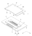
75 접촉편1 is a cross-sectional view of a substrate-cable connection structure according to a first embodiment of the present invention.
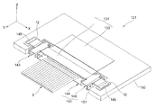
FIG. 2 is a perspective view of the substrate-cable connection structure shown in FIG. 1. FIG.
3 is a perspective view of a relay connector.
4 is an exploded perspective view of the relay connector shown in FIG. 3.
5 is a perspective view showing a modification of the substrate-cable connecting structure according to the first embodiment of the present invention.
6 is a cross-sectional view of a board-cable connection structure according to a second embodiment of the present invention.
7 is a perspective view showing a state in which a cover member of a clamping unit is open.
8 is a perspective view showing a state in which the cover member of the clamping unit is closed.
9 is a perspective view showing a modification of the substrate-cable connecting structure according to the second embodiment.
FIG. 10 is a cross-sectional view of the substrate-cable connection structure shown in FIG. 9. FIG.
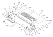
11 is a perspective view of the clamping unit.
12 is a perspective view showing a modification of the substrate-cable connecting structure according to the second embodiment.
13 is a perspective view of an elastic member provided in a plurality of cables.
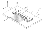
14 is a perspective view of a substrate-cable connection structure according to a third embodiment of the present invention.
FIG. 15 is a partial cross-sectional view of the substrate-cable connection structure shown in FIG. 14. FIG.
16 is a perspective view of a relay connector of the same board-cable connection structure shown in FIG.
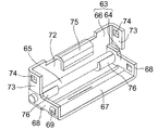
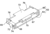
17 is a perspective view showing a state in which the cover member of the clamping unit is open.
18 is a perspective view showing a state in which a relay connector is attached to the clamping unit shown in FIG.
Explanation of reference numerals
1, 51, 81, 101, 121 Board-to-Cable Connection Structure
2, 150 circuit boards
3 cables
4a core
6, 91, 131 relay connector
7 protective cover
9, 59, 89, 133 FPC
11, 82, 132 reputation
15 bulge
15a ceiling wall
15b surrounding wall
16 flat parts
17 long bars
21 opening
63, 83, 143 clamping unit
64, 84, 144 base member
66, 86, 146 cover member
67, 87 Floor Wall
69 locking protrusion
72, 92 upper wall
74, 89 locking holes
75 contact
본 발명의 일 태양에 따르면, 회로 기판, 다수의 케이블, 다수의 케이블을 회로 기판에 전기적으로 중계 및 접속하는 FPC를 갖는 릴레이 커넥터, 및 릴레이 커넥터를 덮으며 릴레이 커넥터가 회로 기판으로부터 분리되는 방향으로 이동하는 것을 방지하는 보호 커버를 포함하는 기판-케이블 접속 구조체가 제공된다.According to one aspect of the invention, a relay connector having a circuit board, a plurality of cables, an FPC for electrically relaying and connecting the plurality of cables to the circuit board, and a relay connector covering the relay connector in a direction in which the relay connector is separated from the circuit board. A substrate-cable connection structure is provided that includes a protective cover to prevent movement.
본 발명의 다른 태양에 따르면, 회로 기판, 다수의 케이블, 다수의 케이블을 회로 기판에 전기적으로 중계 및 접속하는 FPC를 갖는 릴레이 커넥터, 및 릴레이 커넥터의 양측을 클램핑하며 릴레이 커넥터가 회로 기판으로부터 분리되는 방향으로 이동하는 것을 방지하는 클램핑 유닛을 포함하는 기판-케이블 접속 구조체가 제공된다.According to another aspect of the invention, there is provided a circuit board, a plurality of cables, a relay connector having an FPC for electrically relaying and connecting the plurality of cables to the circuit board, and clamping both sides of the relay connector, wherein the relay connector is separated from the circuit board. A substrate-cable connection structure is provided that includes a clamping unit that prevents movement in a direction.
본 발명의 일 태양에 따르면, 케이블 및 회로 기판이 릴레이 커넥터를 통해 접속되기 때문에, 종래의 커넥터를 사용하는 경우에 비하여, 케이블과 회로 기판의 접속부의 구조체는 크기 및 높이가 감소될 수 있다. 릴레이 커넥터는 보호 커버 또는 클램핑 유닛에 의해 회로 기판으로부터 분리되는 방향으로 이동하는 것이 방지되어, 케이블의 코어와 회로 기판의 배선 도체의 접속부에 가해지는 응력이 제거될 수 있다. 따라서, 의도하지 않은 장력이 갑자기 케이블에 가해지는 경우에도, 케이블과 회로 기판 사이의 전기적 접속의 신뢰성은 유지될 수 있다.According to one aspect of the present invention, since the cable and the circuit board are connected via a relay connector, the structure of the connection portion of the cable and the circuit board can be reduced in size and height as compared with the case of using a conventional connector. The relay connector is prevented from moving in the direction separated from the circuit board by the protective cover or the clamping unit, so that the stress applied to the connection portion of the core of the cable and the wiring conductor of the circuit board can be eliminated. Thus, even if an unintentional tension is suddenly applied to the cable, the reliability of the electrical connection between the cable and the circuit board can be maintained.
이제, 본 발명의 다양한 실시예가 구체적이고 예시적인 실시예를 보여주는 도면을 참조하여 아래에서 상세하게 설명될 것이다. 이 실시예들은 대표적인 용도에 사용될 수 있는 기판-케이블 접속 구조체에 관한 것이다. 대표적인 용도에는 클램쉘(clamshell) 유형 또는 슬라이드(slide) 유형의 휴대 전화 및 스마트 폰과 같은 정보 기기가 포함되지만 이것으로 한정되지 않는다. 본 발명에 따른 기판-케이블 접속 구조체는 케이블(소직경 동축 케이블)과 회로 기판을 전기적으로 상호 접속하며, 회로 기판, 일렬로 배열되는 다수의 케이블, 일 단부에서 다수의 케이블에 전기적으로 상호 접속되며 타 단부에서 회로 기판에 전기적으로 중계되는 FPC를 갖는 릴레이 커넥터, 및 회로 기판으로부터 릴레이 커넥터의 분리를 방지하여 케이블과 회로 기판의 전기적 접속을 보호하기 위한 보호 수단을 포함한다. 보호 수단의 예는 나중에 설명되는 바와 같이 보호 커버 및 클램핑 유닛을 포함하지만 이것으로 한정되지 않는다.Various embodiments of the present invention will now be described in detail below with reference to the drawings showing specific and exemplary embodiments. These embodiments relate to substrate-cable connection structures that can be used for representative applications. Typical applications include, but are not limited to, information devices such as clamshell type or slide type mobile phones and smart phones. The board-to-cable connection structure according to the invention electrically interconnects a cable (small diameter coaxial cable) and a circuit board, and is electrically interconnected to a circuit board, a plurality of cables arranged in a row, a plurality of cables at one end. A relay connector having an FPC electrically relayed to the circuit board at the other end, and protection means for preventing the disconnection of the relay connector from the circuit board to protect the electrical connection between the cable and the circuit board. Examples of protective means include, but are not limited to, protective covers and clamping units as described later.
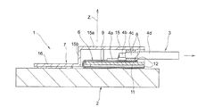
본 발명의 제1 실시예에 따른 기판-케이블 접속 구조체가 아래에 설명될 것이다. 도 1에 도시된 바와 같이, 본 실시예의 기판-케이블 접속 구조체(1)는 회로 기판(2), 일렬로 배열되는 다수의 케이블(3), 케이블(3)의 코어(4a) 및 실드층(4c; shield layer)을 회로 기판(2)의 도체부(5; 도 4 참조)에 중계 및 접속하는 릴레이 커넥터(6), 및 릴레이 커넥터(6)를 덮는 보호 커버(7; 보호 수단)를 포함한다.The substrate-cable connection structure according to the first embodiment of the present invention will be described below. As shown in Fig. 1, the board-to-
회로 기판(2)의 형태에는 PCB(Printed Circuit Board; 인쇄 회로 기판), 가요성을 갖는 FPC(Flexible Printed Circuit; 연성 인쇄 회로) 등이 포함되지만 이것으로 한정되지 않는다. FPC는, 두께가 수 ㎛ 내지 100 ㎛인 예를 들어 폴리이미드 등과 같은 재료로 형성되며 도체부가 기판의 표면 상에 배치되는 연성 회로 기판이다.The form of the
PCB의 대표적인 형태에는 에폭시 수지 등으로 형성되며 다수의 배선 도체가 특정 패턴으로 그 위에 인쇄되는 절연성 기판이 포함된다. 나중에 설명되는 바와 같이, 미리 U자 형상으로 만곡되고 접히는 릴레이 커넥터(6)로서의 FPC(9)가 평판(11)의 앞면과 뒷면 양쪽에 접착되는 제1 실시예에서, 회로 기판(2)과 릴레이 커넥터(6) 사이에 배치된 회로 접속용 접착제를 히터(도시되지 않음)에 의해 회로 기판(2)의 아래쪽으로부터 가열하는 것이 필요하다. 따라서, 열 전도를 손상시키지 않는 재료 및 두께의 회로 기판(2)이 유리하게 사용될 수 있다. FPC(9)의 일 단부가 회로 기판(2)에 접속(고정)된 후에 회로 기판(2)과 함께 FPC(9)의 일 단부가 U자 형상으로 만곡되고 접히는 경우, 회로 기판(2)은 열 전도를 고려하지 않고도 선택될 수 있다. 릴레이 커넥터(6)가 고정되는 회로 기판(2)의 부분에, 배선 도체의 일 단부는 릴레이 커넥터(6)의 다수의 도체에 대응하는 위치에서 노출되어 있다.Representative forms of PCBs include insulating substrates formed of epoxy resins and the like, wherein a plurality of wiring conductors are printed thereon in a specific pattern. As will be explained later, in the first embodiment, in which the
케이블(3)의 일 형태는 외경이 약 0.3 ㎜인 소직경 동축 케이블을 포함한다. 도 1에 도시된 케이블(3)은 중심에 배치된 전도성 코어(4a)를 가지며, 코어(4a)의 외측에 절연성 내측 피복(4b; covering)이 형성되어 있고, 내측 피복(4b)의 외측에 실드층(4c)이 형성되어 있으며, 실드층(4c)의 외측에 절연성 외측 피복(4d)이 형성되어 있다. 이러한 방식으로, 케이블(3)은 신호를 전송하기 위한 코어(4a)와 실드층(4c)이 내측 피복(4b)에 의해 서로 절연되는 다층 구조를 가져서, 신호 전류는 실드층(4c)에 의해 노이즈로부터 보호되어 EMI(electromagnetic interference; 전자파 장애) 특성을 개선시킨다.One form of the
케이블(3)은 외측 피복(4d)과 내측 피복(4b)이 말단부에서 소정 길이만큼 각각 벗겨져 코어(4a)와 실드층(4c)을 노출시키도록 단말 처리된다. 실드층(4c)을 흐르는 노이즈 전류는 회로 기판(2)의 표면 상에 제공된 접지용 배선 도체(도시되지 않음)를 흐르도록 접지 바아(8; ground bar)와 릴레이 커넥터(6)의 FPC의 접지 도체(10b; 도 4)를 통해 전도될 것이다.The
일렬로 배열되는 다수의 케이블(3)은 실드층(4c)에서 한 쌍의 접지 바아(8) 사이에 끼워진다(도 1 및 도 4 참조). 접지 바아(8)와 실드층(4c) 사이의 전기적 접속은 납땜 등에 의해 달성될 수 있다. 케이블 세트는 다수의 케이블(3) 및 한 쌍의 접지 바아(8)로 구성된다. 접지 바아(8)는 예를 들어 프레스에 의해 긴 조각 형상으로 펀칭(punching)함으로써 전도성 구리 합금과 같은 판 재료로 형성된다. 접지 바아(8)에 의해, 모든 케이블(3)의 실드층(4c)이 일괄 접속된다.A plurality of
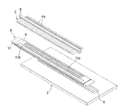
릴레이 커넥터(6)의 일 형태에는 도 3 및 도 4에 도시된 바와 같이 전후 방향으로의 길이 치수(W)가 2 ㎜ 이하, 높이 치수(T)가 1 ㎜ 이하, 횡방향의 폭 치수(L)가 15 ㎜ 이하인 평판(11)이 포함될 수 있지만 이것으로 한정되지 않으며, 평판(11)의 앞면과 뒷면 양쪽에 FPC(9)가 접착되어 있다. FPC(9)는 평판(11)의 양 측면을 남겨 두고서 평판(11)의 앞면과 뒷면 양쪽에 접착될 수 있다. 제2 실시예 및 제3 실시예를 참조하여 설명되는 바와 같이, FPC(9)가 평판(11)의 일 표면에 접착되는 릴레이 커넥터가 사용될 수 있다. 접착제에는 열가소성 접착제, 열경화성 접착제 및 접착 시트가 포함되지만 이것으로 특별히 한정되지 않는다.In one embodiment of the
이러한 실시예에서, FPC(9)는 U자 형상으로 만곡되고 접히며, 평판(11)의 앞면과 뒷면 양쪽에 접착된다. 특히 종방향(폭방향)에서 소정의 정밀도로 평탄하게 형성될 수 있는 한 긴 평판(11)은 금속 또는 수지 재료로 형성될 수 있지만, 평탄 정밀도가 용이하게 제어될 수 있는 금속 재료로 형성되는 것이 바람직하다. 평판(11)의 두께는 필요한 강도가 달성될 수 있는 한 임의적이다. 바람직하게는, 평판(11)의 두께는 약 0.2 ㎜이며, 이 경우 평판(11)은 스테인리스 강으로 형성될 수 있다.In this embodiment, the
두께가 수 ㎛ 내지 100 ㎛인 폴리이미드 등의 기본 재료로 형성되며 도체부가 그 위에 배치된 FPC(9)가 사용될 수 있다. 회로 기판(2)과 케이블(3)로의 전기적 접속을 위해 필요한 부분을 제외하고는, 도체부는 레지스트(resist; 절연성 피복)로 덮인다. FPC의 일 표면은 접착 표면이며, 다른 표면은 전기적 접촉 표면이다. 전기적 접촉 표면은 케이블(3)의 코어(4a)와 접촉하기 위한 도체부(10a), 접지 바아(8)를 통해 케이블(3)의 실드층(4c)과 접촉하기 위한 도체부(10b), 회로 기판(2) 상의 도체부와 접촉하기 위한 도체부(도시되지 않음), 및 회로 기판(2) 상의 접지용 배선 도체와 접촉하기 위한 도체부(도시되지 않음)를 갖는다.An
이러한 실시예에서, FPC(9)가 접착 시트(12)를 통해 양호한 평탄도를 갖는 평판(11)에 접착되기 때문에(도 1), 도체부(10a, 10b)의 각각의 높이의 편차는 작게 유지된다. 릴레이 커넥터(6) 또는 회로 기판(2)이 가열 압착 접합시 압력에 의해 변형되는 경우, 변형 상태로부터의 복원을 위한 복원력이 접속부에 가해지며, 이것은 회로 기판(2)으로부터의 릴레이 커넥터의 분리로 이어질 수 있다. 그러나, 이러한 실시예에서, 도체부(10a, 10b)를 회로 기판(2)의 도체부(5)에 접속하기 위해 과도한 압력이 필요하지 않기 때문에, 릴레이 커넥터(6) 또는 회로 기판(2)의 변형은 억제되고 접속부에 가해지는 응력이 감소되어 접속부의 신뢰성이 향상된다.In this embodiment, since the
도 3은 평판(11)의 앞면에 접착된 FPC의 도체부(10a, 10b)가 납땜에 의해 케이블(3)의 코어(4a) 및 접지 바아(8)에 접속되어 있고, 평판(11)의 뒷면에 접착된 FPC(9)의 도체부가 (이방성 전도성 접착제와 같은) 회로 접속용 접착제를 통해 가열 압착 접합에 의해 회로 기판(2)의 도체부(5)에 접속되어 있는 상태를 보여주는 도면이다. 도시된 바와 같이, 릴레이 커넥터(6)의 앞면은 노출되어 있지만, 릴레이 커넥터를 실드 쉘(shield shell)로 덮는 것도 가능하다. 이 경우, 케이블 인출측에 대응하는 부분의 실드 쉘에 개구가 형성될 수 있다. 접지 바아(8)를 실드 쉘에 납땜하기 위해 납땜용의 복수의 구멍이 실드 쉘에 형성될 수 있거나, 또는 실드 쉘을 릴레이 커넥터(6)에 로킹하기 위해 로킹 수단이 제공될 수 있다. 납땜 등에 의해 보호 커버(7)를 접지 바아(8)에 전기적으로 접속하고 실드 쉘과 동일한 기능을 달성하는 것도 가능하다. 그렇게 함으로써, 릴레이 커넥터(6)와 회로 기판(2) 또는 케이블(3)의 접속부가 차폐되어 EMI 특성을 개선시킬 수 있다.3 shows that
커넥터 하우징 및 단자를 포함하는 종래의 커넥터 대신에 릴레이 커넥터(6)를 사용함으로써, 장착 면적이 감소될 수 있으며 릴레이 커넥터(6)의 (케이블의 길이 방향으로의) 길이가 외측 피복(4d)이 제거된 케이블(3)의 부분과 실질적으로 동일한 길이까지 감소될 수 있다. 릴레이 커넥터의 (정렬된 케이블(3)의 방향으로의) 폭은 다수의 케이블(3)의 폭과 실질적으로 동일한 치수까지 감소될 수 있다.By using the
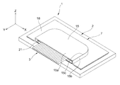
보호 커버(7)는 예를 들어 프레스를 사용함으로써 금속 패널(panel)로부터 형성될 수 있으며, 도 2에 도시된 바와 같이 릴레이 커넥터(6)에 대응하는 크기로 팽출하도록 형성된 팽출부(15; bulging section), 및 팽출부(15)의 주변으로부터 연속되어 회로 기판(2)에 고정되는 평탄부(16; flat section)를 갖는다. 평탄부(16)는 팽출부(15)의 에지에 연속적으로 연결되며, 뒷면은 접착제 등에 의해 회로 기판(2)의 상부 표면에 고정되는 고정 표면을 형성한다. 팽출부(15)는 천장 벽(15a)과, 천장 벽(15a)의 에지(15c)로부터 연속되는 주위 벽(15b)을 갖는다.The
다수의 케이블(3)을 인출하기 위해 팽출부(15)의 주위 벽(15b)에 개구(21)가 형성된다. 팽출부(15)의 높이는 케이블(3)이 부착되어 있는 릴레이 커넥터(6)의 높이와 비견하며, 바람직하게는 보호 커버(7)가 회로 기판(2)에 고정된 상태에서 팽출부(15)의 천장 벽(15a)의 내측 표면과 상부 접지 바아(8) 사이에 갭(gap)이 존재하지 않도록 설정된다. 팽출부(15)의 천장 벽(15a)의 내측 표면을 상부 접지 바아(8)와 접촉시킴으로써, 회로 기판(2)으로부터 분리되는 방향(Z)으로의 릴레이 커넥터(6)의 이동, 다시 말하면 회로 기판(2)으로부터 (수직으로) 일어나는 방향(Z)으로의 릴레이 커넥터(6)의 이동이 방지된다. 따라서, 케이블(3)이 부주의하게 잡아당겨져도, 케이블(3)과 회로 기판(2)의 접속부에 응력이 가해지지 않으며 접속부의 분리가 회피된다. 보호 커버(7)와 전기적으로 접속되어 있는 릴레이 커넥터(6)를 팽출부(15)에 의해 덮음으로써, 케이블 접속 구조체(1)의 차폐 특성이 개선될 수 있다.An
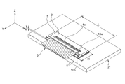
도 5는 제1 실시예의 변형을 보여주는 도면이다. 도시된 바와 같이, 릴레이 커넥터(6)가 회로 기판(2)으로부터 분리되는 것을 방지하기 위해 긴 바아(17; 분리 방지 부재)가 다수의 케이블(3)의 주위에 개장(retrofit)된다. 긴 바아(17)는 필요한 강도를 갖는 임의의 재료, 예를 들어 열가소성 수지 재료로 형성될 수 있다. 긴 바아(17)가 개장될 때, 긴 바아는 케이블(3)을 상부 수지 부재(18a)와 하부 수지 부재(18b) 사이에 끼우도록 제공될 수 있다. 긴 바아(17)를 다수의 케이블(3)과 일체로 제공하는 것도 가능하며, 이 경우 긴 바아(17)는 수지로부터 성형될 수 있다. 보호 커버(7)는 케이블(3)을 인출하기 위한 개구(21)의 양측에 제공된, 긴 바아(17)의 양측을 로킹하기 위한 로킹 벽(20; 주위 벽(15b))을 갖는다. 케이블(3)이 잡아당겨질 때, 긴 바아(17)는 로킹 벽(20)의 내측 표면에 맞닿게 되고, 이에 의해 릴레이 커넥터(6)가 전후 방향으로 이동하는 것을 방지한다. 이에 의해 릴레이 커넥터(6)가 다수의 케이블(3)과 함께 회로 기판(2)으로부터 분리되는 것이 방지된다.5 is a diagram showing a variation of the first embodiment. As shown, an elongated bar 17 (separation preventing member) is retrofitted around the plurality of
회로 기판 및 보호 커버와 접촉하고 있는 긴 바아의 표면에 예를 들어 접착제를 도포함으로써 접착 특성을 부여하고, 이에 의해 팽출부(15)의 주위 벽(15b)에 형성된 개구(21)를 긴 바아로 밀봉하는 것이 또한 가능하다. 대안적으로, 긴 바아를 다수의 케이블(3)의 주위에 일체 형성된 탄성 재료로서 형성하고 긴 바아를 보호 커버와 회로 기판 사이에서 탄성적으로 압축함으로써 팽출부(15)의 주위 벽(15b)에 형성된 개구(21)를 긴 바아로 밀봉하는 것이 또한 가능하다. 개구(21)를 긴 바아로 밀봉함으로써, 물과 같은 액체 또는 먼지가 보호 커버(7)의 내부로 유입하는 것이 방지될 수 있다.Adhesion properties are imparted, for example, by applying an adhesive to the surface of the long bar in contact with the circuit board and the protective cover, whereby the
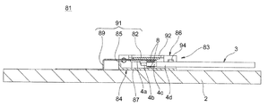
다음으로, 본 발명의 제2 실시예에 따른 기판-케이블 접속 구조체가 설명될 것이다. 도 6 내지 도 8에 도시된 바와 같이, 본 실시예에 따른 기판-케이블 접속 구조체(51)는, 릴레이 커넥터(6)의 평판(11)이 양측에서 클램핑 유닛(63; 보호 수단)에 의해 회로 기판(2) 상에 클램핑되고 보호 커버(7)가 사용되지 않는다는 점에서, 제1 실시예에 따른 기판-케이블 접속 구조체(1)와 상이하다.Next, a substrate-cable connecting structure according to the second embodiment of the present invention will be described. As shown in Figs. 6 to 8, in the board-to-
도 1에 도시된 보호 커버와 마찬가지로, 클램핑 유닛(63)은 릴레이 커넥터(6)가 회로 기판(2)으로부터 분리되는 방향, 주로 수직 방향(Z)으로 이동하는 것을 방지하여, 케이블(3)이 갑자기 부주의하게 잡아당겨져도 코어(4a)와 회로 기판(2)의 도체부(5)의 접속부에 응력이 가해지지 않는다. 본 실시예에 따른 클램핑 유닛(63)은 회로 기판(2) 상에 고정되는 기부 부재(64), 및 개폐가 가능하게 되도록 상호 연결 핀(65)을 통해 기부 부재(64)에 상호 연결되는 커버 부재(66)로 구성되는데, 이 클램핑 유닛(63)의 구성은 그러한 구성으로 제한되는 것은 아니다(도 7 및 도 8). 상호 연결 핀(65)을 사용하지 않고도 커버 부재를 기부 부재에 탈착식으로 상호 연결하는 것이 또한 가능하다.Like the protective cover shown in FIG. 1, the clamping
도 7 및 도 8에 도시된 바와 같이, 기부 부재(64)는 예를 들어 프레스를 사용하여 얇은 판 금속 패널을 펀칭하고 만곡시킴으로써 형성될 수 있으며, 바닥 벽(67) 및 양 측벽(68)을 갖는다. 릴레이 커넥터(6)의 단부(평판(11)의 단부)는 양 측벽(68)의 일 단부에 개구로서 형성된 삽입 단부로부터 부착될 수 있다. 삽입 단부의 반대 측에서, 상호 연결 핀(65)이 양 측벽(68) 내로 압입되고, 커버 부재(66)가 상호 연결 핀(65)에 회전가능하게 상호 연결된다. 기부 부재(64)의 바닥 벽(67)의 하부 표면은 접착제 또는 납땜에 의해 회로 기판(2)의 상부 표면에 고정되는 고정 표면이다. 기부 부재(64)의 바닥 벽(67)으로부터 직립하는 양 측벽(68)의 외측 표면에, 로킹 돌출부(69)가 커버 부재(66)의 측벽(73)에 제공된 로킹 구멍(74)과 결합하도록 제공된다. 로킹 돌출부(69)는 커버 부재(66)의 측벽(73)의 말단부가 그 위에서 활주하는 경사 표면, 및 경사 표면으로부터 연속되며 로킹 구멍(74)의 구멍 에지에 맞닿는 로킹 표면을 가질 수 있다. 기부 부재(64)의 양 측벽(68)들 사이에, 릴레이 커넥터(6)가 대향하는 양 측벽(68)의 방향, 즉 도 6에 도시된 전후 방향(Y)으로 이동하는 것을 방지하기 위해 릴레이 커넥터(6)의 평판(11)의 단부가 부착된다.As shown in FIGS. 7 and 8, the
기부 부재(64)와 마찬가지로, 커버 부재(66)도 또한 예를 들어 프레스를 사용하여 얇은 판 금속 패널을 펀칭하고 만곡시킴으로써 형성될 수 있으며, 상부 벽(72) 및 양 측벽(73)을 갖는다. 양 측벽(73)의 일측에, 상부 벽(72)의 단부에서 기부 단부로부터 말단부까지 안쪽으로 만곡되고 내부로 연장되는 혀(tongue) 모양의 접촉편(75)과, 양 측벽(73)의 타측에 상호 연결 핀(65)에 상호 연결되는 한 쌍의 상호 연결편(76; interconnecting piece)을 갖는다. 접촉편(75)은 평판(11)의 상부 표면과 접촉할 수 있도록 제공되어, 평판(11)과 결합되면 릴레이 커넥터(6)가 회로 기판(2)으로부터 일어나는 방향(Z), 즉 릴레이 커넥터가 회로 기판(2)으로부터 분리되는 방향으로 이동하는 것을 방지한다. 로킹 구멍(74)이 커버 부재(66)의 양 측벽(73)에 제공되어, 커버 부재(66)의 측벽(73)이 기부 부재(64)의 측벽(68)의 외측 표면에 겹쳐지고 로킹 구멍(74)이 로킹 돌출부(69)와 결합될 때, 커버 부재(66)는 기부 부재(64)에 로킹된다.Like the
본 실시예에 따른 클램핑 유닛(63)이 기계적 로킹 기구를 포함하기 때문에, 로킹을 해제하고 커버 부재(66)를 개방함으로써 클램핑 해제 상태가 달성될 수 있다. 클램핑 해제 상태에서, 릴레이 커넥터(6)의 교환 및 유비 보수가 행해질 수 있다.Since the clamping
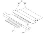
도 9 및 도 10은 제2 실시예의 변형을 보여주는 도면이다. 이러한 변형에서, 클램핑 유닛(83)의 기부 부재(84)는 하나의 구성요소로서 형성된다. 릴레이 커넥터(91)는 평판(82)의 일 표면에만 접착되는 FPC(89)를 갖는다. FPC(89)는 일 단부로부터 타 단부까지 연장되며, 케이블(3)에 접속되는 일 단부는 평판(82)에 고정되고, 타 단부는 회로 접속용 접착제를 통해 가열 압착 접합에 의해 회로 기판(2)에 고정된다.9 and 10 show a variation of the second embodiment. In this variant, the
이러한 변형에서, 릴레이 커넥터(91)는 케이블(3)에 접속되는 FPC(89)의 표면이 회로 기판(2)을 향하도록 고정된다. 릴레이 커넥터(91)를 그렇게 고정함으로써, 회로 기판(2)에 대한 FPC(89)의 위치설정이 용이해진다. 평판(82)이 케이블(3)과 FPC(89)의 접속부를 덮기 때문에, 보호 커버 없이도 갑작스런 단락(short-circuiting)이 회피될 수 있다. FPC(89)의 도체부가 일 표면에서만 노출될 필요가 있기 때문에 FPC(89) 자체의 구성이 간소화될 수 있으며, FPC(89)의 상부 표면과 하부 표면 사이의 전도를 위한 비아 도체(via conductor)의 필요성이 없어지기 때문에 FPC(89)의 크기를 감소시키는 것이 가능하다.In this variant, the
도 11에 상세히 도시된 바와 같이, 커버 부재(86)는 기부 부재(84)의 양측에서 상호 연결 핀(85)을 통해 회전가능하게 상호 연결된다. 도시된 바와 같이, 릴레이 커넥터(91)의 평판(82)의 양측은 기부 부재(84)의 양 측부와 개폐 작동시 이동하는 커버 부재(86) 사이에 클램핑된다.As shown in detail in FIG. 11, the
기부 부재(84)는 바닥 벽(87), 바닥 벽(87)의 양측에서 수직으로 직립하는 측벽(88), 및 측벽(88)에 대향하는 한 쌍의 만곡편(90a, 90b; bent piece)을 갖는다. 상호 연결 핀(85)은 만곡편들 중의 일 만곡편(90a)과 그 만곡편(90a)에 대향하는 측벽(88)에 형성된 관통 구멍 내로 압입된다. 커버 부재(86)의 일 단부에 U자 형상으로 형성된 연결부(97)가 상호 연결 핀(85)에 회전가능하게 연결된다. 커버 부재(86)의 측벽(93) 상에 제공된 로킹 돌출부(도시되지 않음)와 결합하는 로킹 구멍(94)이 다른쪽 만곡편(90b)에 형성된다. 로킹 구멍(94)은 또한 만곡편(90b)에 형성된 로킹 구멍(94)에 대향하는 위치의 기부 부재(84)의 측벽(88)에 형성된다 커버 부재(86)의 측벽(93) 상에 제공된 로킹 돌출부가 만곡편(90b) 및 측벽(88)에 제공된 2개의 로킹 구멍(94)과 결합될 때, 커버 부재(86)는 기부 부재(84)에 로킹되며, 릴레이 커넥터(91)의 평판(82)의 양측은 기부 부재(84)와 커버 부재(86) 사이에 클램핑된다.
커버 부재(86)는 상부 벽(92), 상부 벽(92)의 에지로부터 연속되어 기부 부재(84)의 측벽(88) 및 만곡편(90b)에 겹쳐지는 측벽(93), 및 기부 부재(84)에 제공된 상호 연결 핀(85)에 회전가능하게 상호 연결되는 U자 형상의 연결부(97)를 갖는다. 기부 부재(84)의 측벽(88) 및 만곡편(90b)에 형성된 로킹 구멍(94)과 결합되는 위치의 측벽(93) 상에 로킹 돌출부가 형성된다. 바람직하게는, 커버 부재(86)는 기부 부재(84)의 측벽(88)과 한 쌍의 만곡편(90b) 사이에 탄성적으로 끼워지기에 적합한 치수로 형성된다. 이에 의해 클램핑 상태에서 기부 부재(84)와 커버 부재(86)의 헐거움이 효과적으로 억제될 수 있다.The
클램핑 유닛(83)의 클램핑 상태에서, 릴레이 커넥터(91)의 평판(82)의 양측은 기부 부재(84)의 바닥 벽(87)과 커버 부재(86)의 상부 벽(92) 사이에 클램핑된다. 평판(82)이 기부 부재(84)의 양 측벽(88)들 사이에 위치되기 때문에 릴레이 커넥터(91)는 좌우 방향(X)으로 이동하는 것이 방지되고, 평판(82)이 한 쌍의 만곡편(90a, 90b) 사이에 위치되기 때문에 릴레이 커넥터(91)는 전후 방향(Y)으로 이동하는 것이 방지되며, 평판(82)이 기부 부재(84)의 바닥 벽(87)과 커버 부재(86)의 상부 벽(92) 사이에 위치되기 때문에 릴레이 커넥터(91)는 상하 방향(Z)으로 이동하는 것이 방지된다(도 9 참조). 이러한 변형에서, 도 7에 도시된 혀 모양의 접촉편(75)에 대응하는 부분이 기부 부재(84) 또는 커버 부재(86)에 제공될 수 있다.In the clamping state of the clamping
도 12는 제2 실시예의 다른 변형을 보여주는 도면이다. 도시된 바와 같이, 이러한 변형에서, 릴레이 커넥터(91) 및 클램핑 유닛(83)을 덮기 위한 보호 커버(7), 및 다수의 케이블(3)의 주위에 일체로 제공되는 긴 바아(110)가 포함된다. 보호 커버(7)는 도 2에 도시된 보호 커버(7)에 상당하기 때문에, 보호 커버(7)에 대한 중복 설명은 생략한다. 케이블 접속 구조체(101)의 차폐 특성은 릴레이 커넥터(91)를 덮는 보호 커버(7)에 의해 개선된다.12 is a view showing another modification of the second embodiment. As shown, in this variant, a
도 13에 도시된 바와 같이, 긴 바아(110)는 바람직하게는 다수의 케이블(3)과 긴 바아(110) 사이에 어떠한 갭도 없도록 수지 성형에 의해 일체로 제공되어 팽출부(15)의 주위 벽(15b)에 형성된 개구(21)를 밀봉한다. 긴 바아(110)로 개구(21)를 밀봉함으로써, 물과 같은 액체 또는 먼지가 외부로부터 보호 커버(7) 내로 유입하는 것이 회피될 수 있으며 케이블(3) 및 회로 기판(2)의 방수 특성 및 방진(dust-proof) 특성이 개선될 수 있다. 릴레이 커넥터(91)는 보호 커버(7)의 로킹 벽(20)에 맞닿는 긴 바아에 의해 전후 방향(Y)으로 이동하는 것이 방지된다(도 5 참조).As shown in FIG. 13, the
긴 바아(110)는 도 5에 도시된 긴 바아(17)에 대응하는 부재이며, 접착제가 긴 바아(110)에 도포되어 개구(21)를 밀봉할 수 있다. 대안적으로, 긴 바아(110)는 보호 커버(7)와 회로 기판(2) 사이에서 탄성적으로 압축되어 개구(21)를 밀봉할 수 있다.The
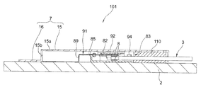
다음으로, 본 발명의 제3 실시예에 따른 기판-케이블 접속 구조체가 설명될 것이다. 도 14 내지 도 18에 도시된 바와 같이, 본 실시예의 기판-케이블 접속 구조체(121)는, 릴레이 커넥터(131)의 평판(132)의 양측을 클램핑하기 위한 클램핑 유닛(143)이 회로 기판(150)의 주변에 제공된 오목부(151) 내에 배치되는 반면에 제2 실시예의 기판-케이블 접속 구조체(81, 101)에서는 클램핑 유닛(83)이 회로 기판(150) 상에 제공된다는 점에서, 제2 실시예의 기판-케이블 접속 구조체(81, 101)와 상이하다. 기판-케이블 접속 구조체(121)가 오목부(151) 내에 배치되기 때문에, 기판-케이블 접속 구조체(121)는 회로 기판(150)의 두께 방향으로 돌출하는 것이 방지되며, 이는 높이 치수를 작게 유지하고 얇은 외피(enclosure)를 달성하는 것을 가능하게 한다.Next, a board-cable connection structure according to the third embodiment of the present invention will be described. As shown in FIGS. 14 to 18, the board-to-
도 14 및 도 15에 도시된 바와 같이, 클램핑 유닛(143)에 대응하는 크기의 오목부(151)가 회로 기판(150)의 일측의 주변에 제공된다. 클램핑 유닛(143)은 오목부(151) 내에 대체로 수용되도록 배치된다. 클램핑 유닛(143)은 기부 부재(144)의 양측으로부터 폭방향으로 연장되는 한 쌍의 아암(145)이 회로 기판(150)에 납땜되게 함으로써 회로 기판(150)에 고정되지만, 그러한 구성으로 한정되지 않는다. 클램핑 유닛(143) 및 회로 기판(150)은 접착제에 의해, 나사 체결에 의해 또는 스냅-끼워맞춤(snap-fit) 방법에 의해 서로 고정될 수 있다. 클램핑 유닛(143)이 회로 기판(150)에 고정되는 대신에, 회로 기판이 그 안에 수용되는 외피, 예를 들어 휴대 전화의 외피의 내측 표면에 클램핑 유닛(143)을 고정하기 위해 클램핑 유닛(143)의 기부의 뒷면에 접착제가 제공될 수 있다.As shown in FIG. 14 and FIG. 15, a
도 16은 뒷면 쪽에서 본, 본 실시예의 클램핑 유닛(143)에 의해 클램핑된 릴레이 커넥터(131)를 보여주는 도면이다. FPC(133)의 일측에서, 케이블(3)의 코어(4a)가 뒷면에 노출된 신호 배선 도체(10a)에 납땜된다. 케이블(3)의 실드층(4c)에 접속된 한 쌍의 접지 바아(8)가 FPC(133) 접지용 접지 배선 도체(10b)에 납땜된다. 평판(132)은 접착제 등에 의해 FPC(133)의 앞면에 접합된다. 평판(132)의 양측은 FPC(133)의 폭방향으로 양측에서 연장되어, 그 연장부가 클램핑 유닛(143)에 의해 클램핑될 수 있다. FPC(133)의 타측에서, 회로 기판(150)에 가열 압착 접합되는 FPC(133)의 뒷면에 신호 배선 도체(10a)가 노출되어 있다.16 shows the
도 17은 회로 기판(150)의 오목부(151) 내에 배치되는 클램핑 유닛(143)을 보여주는 도면이다. 기부 부재(144)가 한 쌍의 아암(145)에 의해 회로 기판(150)에 고정된다는 것을 제외하고는, 이 기부 부재는 도 11에 도시된 기부 부재(84)와 동일하다. 기부 부재(144)의 양측에서, 커버 부재(146)는 상호 연결 핀(85)을 통해 회전가능하게 상호 연결된다. 상호 연결 핀(85)은 하나의 만곡편(90a) 및 만곡편(90a)에 대향하는 측벽(88)에 형성된 관통 구멍 내로 압입된다.17 illustrates a
기부 부재(144)는 바닥 벽(87), 바닥 벽(87)의 양측에서 수직으로 직립하는 측벽(88), 및 측벽(88)에 대향하는 한 쌍의 만곡편(90a, 90b)을 갖는다. 상호 연결 핀(85)은 만곡편들 중의 일 만곡편(90a) 내로 압입되며, 다른쪽 만곡편(90b)에 커버 부재(146)의 측벽(93) 상에 제공된 로킹 돌출부(153)와 결합되는 로킹 구멍(94)이 형성된다. 로킹 구멍(94)은 또한 만곡편(90b)에 형성된 로킹 구멍에 대향하는 위치의 기부 부재(144)의 측벽(88)에 형성된다. 커버 부재(146)의 측벽(93) 상에 제공된 로킹 돌출부(153)와 만곡편(90b) 및 측벽(88)에 제공된 2개의 로킹 구멍(94)의 결합에 의해, 커버 부재(86)는 기부 부재(84)에 로킹되며, 릴레이 커넥터(131)의 평판(132)의 양측은 기부 부재(144)와 커버 부재(146) 사이에 클램핑된다. 회로 기판(150)에 고정되는 아암(145)이 측벽(88)의 각각에 제공된다. 아암(145)은 측벽(88)으로부터 연속되는 기부측, 및 이 기부측으로부터 연속되며 회로 기판(150)에 평행하게 만곡되는 말단측을 갖는다. 아암(145)은 말단부의 평탄한 표면에서 회로 기판(150)에 접착된다.The
커버 부재(146) 또한 도 11에 도시된 커버 부재(86)와 유사하며, 상부 벽(92), 상부 벽(92)의 에지로부터 연장되며 기부 부재(144)의 측벽(88) 및 만곡편(90b)에 겹쳐지는 측벽(93), 및 상호 연결 핀(85)에 회전가능하게 상호 연결되는 U자 형상의 연결부(97)를 갖는다. 기부 부재(144)의 측벽(88) 및 만곡편(90b)에 형성된 로킹 구멍(94)과 결합되는 위치의 측벽(93) 상에 로킹 돌출부(153)가 형성된다.The
도 18은 클램핑 해제 상태의 클램핑 유닛(143)에 부착된 릴레이 커넥터(131)를 보여주는 도면이다. 평판(131)의 양측은 기부 부재(144)의 양측과 커버 부재(146) 사이에 위치된다. 커버 부재(146)를 폐쇄함으로써, 평판(132)의 양측은 기부 부재(144)의 양측과 커버 부재(146) 사이에 클램핑된다. 도 15에 도시된 바와 같이, 클램핑 상태에서, 평판(132)의 양측은 바람직하게는 커버 부재(146)의 상부 벽(92)의 하면과 갭 없이 밀접하게 접촉하며, 평판(132)의 양측은 바람직하게는 커버 부재(146)의 측벽(93)의 내측 표면과 접촉한다. 이에 의해 릴레이 커넥터(131)는 헐거움 없이 클램핑 유닛에 의해 고정될 수 있다. 이러한 실시예에서, 도 7에 도시된 혀 모양의 접촉편(75)에 대응하는 부분을 기부 부재(144) 또는 커버 부재(146)에 제공하는 것도 가능하다.18 is a view showing a
제3 실시예에 따르면, 릴레이 커넥터(131)는 클램핑 유닛(143)에 의해 좌우 방향(X), 전후 방향(Y) 그리고 상하 방향(Z)으로 이동하는 것이 방지된다. 클램핑 유닛(143)이 회로 기판(150)의 오목부(151) 내에 배치되기 때문에, 회로 기판(150)으로부터의 클램핑 유닛(143)의 돌출이 억제되며, 따라서 본 발명의 접속 구조체(121)의 크기 및 높이가 더 감소될 수 있다.According to the third embodiment, the
본 발명에 따른 기판-케이블 접속 구조체가 그 실시예를 참조하여 위에서 설명되었다. 그러나, 본 발명은 다른 형태로 구현될 수 있으며, 첨부된 특허청구범위 및 그 등가물에 의해서만 제한되어야 한다.The substrate-cable connection structure according to the present invention has been described above with reference to the embodiment. However, the present invention may be embodied in other forms and should be limited only by the appended claims and their equivalents.
Claims (8)
다수의 케이블;
상기 다수의 케이블을 상기 회로 기판에 전기적으로 중계 및 접속하는, FPC를 갖는 릴레이 커넥터(relay connector); 및
상기 릴레이 커넥터를 덮으며, 상기 회로 기판으로부터 상기 릴레이 커넥터를 분리시키는 방향으로 상기 릴레이 커넥터가 이동하는 것을 방지하는 보호 커버
를 포함하는 기판-케이블 접속 구조체.A circuit board;
Multiple cables;
A relay connector having an FPC, which electrically relays and connects the plurality of cables to the circuit board; And
A protective cover covering the relay connector and preventing the relay connector from moving in a direction of separating the relay connector from the circuit board
Substrate-cable connection structure comprising a.
다수의 케이블;
상기 다수의 케이블을 상기 회로 기판에 전기적으로 중계 및 접속하는, FPC를 갖는 릴레이 커넥터; 및
상기 릴레이 커넥터의 양측을 클램핑하며, 상기 회로 기판으로부터 상기 릴레이 커넥터를 분리시키는 방향으로 상기 릴레이 커넥터가 이동하는 것을 방지하는 클램핑 유닛(clamping unit)
을 포함하는 기판-케이블 접속 구조체.A circuit board;
Multiple cables;
A relay connector having an FPC, which electrically relays and connects the plurality of cables to the circuit board; And
A clamping unit for clamping both sides of the relay connector and preventing the relay connector from moving in a direction of separating the relay connector from the circuit board
Substrate-cable connection structure comprising a.
Applications Claiming Priority (2)
| Application Number | Priority Date | Filing Date | Title |
|---|---|---|---|
| JPJP-P-2008-262102 | 2008-10-08 | ||
| JP2008262102A JP2010092740A (en) | 2008-10-08 | 2008-10-08 | Board-cable connection structure |
Publications (1)
| Publication Number | Publication Date |
|---|---|
| KR20110082543A true KR20110082543A (en) | 2011-07-19 |
Family
ID=42101154
Family Applications (1)
| Application Number | Title | Priority Date | Filing Date |
|---|---|---|---|
| KR1020117010234A KR20110082543A (en) | 2008-10-08 | 2009-10-05 | Board cable connection structure |
Country Status (3)
| Country | Link |
|---|---|
| JP (1) | JP2010092740A (en) |
| KR (1) | KR20110082543A (en) |
| WO (1) | WO2010042420A2 (en) |
Families Citing this family (3)
| Publication number | Priority date | Publication date | Assignee | Title |
|---|---|---|---|---|
| JP6084010B2 (en) * | 2011-11-25 | 2017-02-22 | キヤノン株式会社 | Imaging device having a configuration capable of preventing disconnection of connector |
| CN108075266A (en) * | 2016-11-14 | 2018-05-25 | 英业达科技有限公司 | Cable connector assembly |
| CN112310843B (en) * | 2020-10-26 | 2022-07-08 | 国网山东省电力公司昌邑市供电公司 | Put relay protection device on spot |
Family Cites Families (7)
| Publication number | Priority date | Publication date | Assignee | Title |
|---|---|---|---|---|
| JPS61138181U (en) * | 1985-02-16 | 1986-08-27 | ||
| JPH09266038A (en) * | 1996-03-29 | 1997-10-07 | Mitsubishi Electric Corp | Connector |
| JP2000182682A (en) * | 1998-12-18 | 2000-06-30 | Sumitomo Wiring Syst Ltd | Electric junction box |
| JP2000195619A (en) * | 1998-12-25 | 2000-07-14 | Ace Five:Kk | Cable assembly |
| JP2005141930A (en) * | 2003-11-04 | 2005-06-02 | Molex Inc | Cable connector |
| JP4822983B2 (en) * | 2006-08-23 | 2011-11-24 | モレックス インコーポレイテド | Relay connector |
| JP2008235183A (en) * | 2007-03-23 | 2008-10-02 | Tyco Electronics Amp Korea Ltd | Electrical connector |
-
2008
- 2008-10-08 JP JP2008262102A patent/JP2010092740A/en active Pending
-
2009
- 2009-10-05 WO PCT/US2009/059491 patent/WO2010042420A2/en active Application Filing
- 2009-10-05 KR KR1020117010234A patent/KR20110082543A/en not_active Application Discontinuation
Also Published As
| Publication number | Publication date |
|---|---|
| JP2010092740A (en) | 2010-04-22 |
| WO2010042420A3 (en) | 2010-07-15 |
| WO2010042420A2 (en) | 2010-04-15 |
Similar Documents
| Publication | Publication Date | Title |
|---|---|---|
| US20090208168A1 (en) | Connector, optical transmission module and optical-electrical transmission module | |
| US8317543B2 (en) | Electrical connector | |
| KR20080034853A (en) | Electrical interconnection system | |
| JP2017103223A (en) | Rigid-flex circuit connector | |
| US11424579B2 (en) | Connector and connector device | |
| US11404811B2 (en) | Small form factor interposer | |
| US11777259B2 (en) | Electrical connector with protrusions on the outer peripheral wall of the shield and device using the same | |
| US11211728B2 (en) | Midboard cable terminology assembly | |
| US20080026609A1 (en) | Low profile connector | |
| CN113131289A (en) | Connector and connector device | |
| CN111082242A (en) | Connector, circuit board and communication equipment | |
| KR20110082543A (en) | Board cable connection structure | |
| JPH09274969A (en) | Connector | |
| TWI555280B (en) | Electrical connector | |
| TWI497839B (en) | Electrical connector | |
| JP2010160976A (en) | Connector device | |
| JP4347365B2 (en) | Multi-pole connector | |
| JP2008140555A (en) | Connector device | |
| US11289841B2 (en) | Cable connector | |
| US6004145A (en) | Cable-to-board arrangements for enhanced RF shielding | |
| JP2009037773A (en) | Connector, cable connecting structure, electronic device and connecting method of connector and base board | |
| JP7196402B2 (en) | connector device | |
| JP4218852B2 (en) | Circuit unit | |
| JP7133516B2 (en) | Signal transmission circuit, electronic control unit | |
| CN110113871B (en) | Circuit board assembly and electronic equipment |
Legal Events
| Date | Code | Title | Description |
|---|---|---|---|
| WITN | Application deemed withdrawn, e.g. because no request for examination was filed or no examination fee was paid |