KR20110049819A - Swing prism endoscope - Google Patents
Swing prism endoscope Download PDFInfo
- Publication number
- KR20110049819A KR20110049819A KR1020117004165A KR20117004165A KR20110049819A KR 20110049819 A KR20110049819 A KR 20110049819A KR 1020117004165 A KR1020117004165 A KR 1020117004165A KR 20117004165 A KR20117004165 A KR 20117004165A KR 20110049819 A KR20110049819 A KR 20110049819A
- Authority
- KR
- South Korea
- Prior art keywords
- endoscope
- sinus
- catheter
- shaft
- opening
- Prior art date
Links
Images


Classifications
-
- A—HUMAN NECESSITIES
- A61—MEDICAL OR VETERINARY SCIENCE; HYGIENE
- A61B—DIAGNOSIS; SURGERY; IDENTIFICATION
- A61B1/00—Instruments for performing medical examinations of the interior of cavities or tubes of the body by visual or photographical inspection, e.g. endoscopes; Illuminating arrangements therefor
- A61B1/233—Instruments for performing medical examinations of the interior of cavities or tubes of the body by visual or photographical inspection, e.g. endoscopes; Illuminating arrangements therefor for the nose, i.e. nasoscopes, e.g. testing of patency of Eustachian tubes
-
- A—HUMAN NECESSITIES
- A61—MEDICAL OR VETERINARY SCIENCE; HYGIENE
- A61B—DIAGNOSIS; SURGERY; IDENTIFICATION
- A61B1/00—Instruments for performing medical examinations of the interior of cavities or tubes of the body by visual or photographical inspection, e.g. endoscopes; Illuminating arrangements therefor
- A61B1/00002—Operational features of endoscopes
- A61B1/00039—Operational features of endoscopes provided with input arrangements for the user
- A61B1/00042—Operational features of endoscopes provided with input arrangements for the user for mechanical operation
-
- A—HUMAN NECESSITIES
- A61—MEDICAL OR VETERINARY SCIENCE; HYGIENE
- A61B—DIAGNOSIS; SURGERY; IDENTIFICATION
- A61B1/00—Instruments for performing medical examinations of the interior of cavities or tubes of the body by visual or photographical inspection, e.g. endoscopes; Illuminating arrangements therefor
- A61B1/00064—Constructional details of the endoscope body
- A61B1/00066—Proximal part of endoscope body, e.g. handles
-
- A—HUMAN NECESSITIES
- A61—MEDICAL OR VETERINARY SCIENCE; HYGIENE
- A61B—DIAGNOSIS; SURGERY; IDENTIFICATION
- A61B1/00—Instruments for performing medical examinations of the interior of cavities or tubes of the body by visual or photographical inspection, e.g. endoscopes; Illuminating arrangements therefor
- A61B1/00064—Constructional details of the endoscope body
- A61B1/00071—Insertion part of the endoscope body
- A61B1/0008—Insertion part of the endoscope body characterised by distal tip features
- A61B1/00096—Optical elements
-
- A—HUMAN NECESSITIES
- A61—MEDICAL OR VETERINARY SCIENCE; HYGIENE
- A61B—DIAGNOSIS; SURGERY; IDENTIFICATION
- A61B1/00—Instruments for performing medical examinations of the interior of cavities or tubes of the body by visual or photographical inspection, e.g. endoscopes; Illuminating arrangements therefor
- A61B1/00163—Optical arrangements
- A61B1/00174—Optical arrangements characterised by the viewing angles
- A61B1/00183—Optical arrangements characterised by the viewing angles for variable viewing angles
-
- A—HUMAN NECESSITIES
- A61—MEDICAL OR VETERINARY SCIENCE; HYGIENE
- A61B—DIAGNOSIS; SURGERY; IDENTIFICATION
- A61B1/00—Instruments for performing medical examinations of the interior of cavities or tubes of the body by visual or photographical inspection, e.g. endoscopes; Illuminating arrangements therefor
- A61B1/06—Instruments for performing medical examinations of the interior of cavities or tubes of the body by visual or photographical inspection, e.g. endoscopes; Illuminating arrangements therefor with illuminating arrangements
- A61B1/0625—Instruments for performing medical examinations of the interior of cavities or tubes of the body by visual or photographical inspection, e.g. endoscopes; Illuminating arrangements therefor with illuminating arrangements for multiple fixed illumination angles
-
- G—PHYSICS
- G02—OPTICS
- G02B—OPTICAL ELEMENTS, SYSTEMS OR APPARATUS
- G02B23/00—Telescopes, e.g. binoculars; Periscopes; Instruments for viewing the inside of hollow bodies; Viewfinders; Optical aiming or sighting devices
- G02B23/24—Instruments or systems for viewing the inside of hollow bodies, e.g. fibrescopes
- G02B23/2407—Optical details
- G02B23/2423—Optical details of the distal end
-
- G—PHYSICS
- G02—OPTICS
- G02B—OPTICAL ELEMENTS, SYSTEMS OR APPARATUS
- G02B26/00—Optical devices or arrangements for the control of light using movable or deformable optical elements
- G02B26/08—Optical devices or arrangements for the control of light using movable or deformable optical elements for controlling the direction of light
- G02B26/0875—Optical devices or arrangements for the control of light using movable or deformable optical elements for controlling the direction of light by means of one or more refracting elements
- G02B26/0883—Optical devices or arrangements for the control of light using movable or deformable optical elements for controlling the direction of light by means of one or more refracting elements the refracting element being a prism
-
- A—HUMAN NECESSITIES
- A61—MEDICAL OR VETERINARY SCIENCE; HYGIENE
- A61B—DIAGNOSIS; SURGERY; IDENTIFICATION
- A61B17/00—Surgical instruments, devices or methods, e.g. tourniquets
- A61B17/24—Surgical instruments, devices or methods, e.g. tourniquets for use in the oral cavity, larynx, bronchial passages or nose; Tongue scrapers
Landscapes
- Health & Medical Sciences (AREA)
- Life Sciences & Earth Sciences (AREA)
- Physics & Mathematics (AREA)
- Surgery (AREA)
- Optics & Photonics (AREA)
- Engineering & Computer Science (AREA)
- Heart & Thoracic Surgery (AREA)
- Public Health (AREA)
- Medical Informatics (AREA)
- Molecular Biology (AREA)
- Radiology & Medical Imaging (AREA)
- Veterinary Medicine (AREA)
- Biophysics (AREA)
- Biomedical Technology (AREA)
- General Health & Medical Sciences (AREA)
- Nuclear Medicine, Radiotherapy & Molecular Imaging (AREA)
- Pathology (AREA)
- Animal Behavior & Ethology (AREA)
- General Physics & Mathematics (AREA)
- Astronomy & Astrophysics (AREA)
- Otolaryngology (AREA)
- Mechanical Engineering (AREA)
- Endoscopes (AREA)
- Surgical Instruments (AREA)
Abstract
가변 관찰 방향 내시경이 시각화를 달성하기 위해 귀, 코, 목구멍, 부비동 또는 두개골 내의 원하는 위치에 위치가능하다. 사용 방법은 가변 관찰 방향 내시경을, 내시경이 내시경의 종축에 대해 약 0도 내지 약 15도의 제1 관찰 방향으로 조절된 상태로, 비강 내로 도입하는 단계를 포함한다. 치료 장치가 비강 내로 도입되고, 내시경은 부비동 개방부 또는 통로를 향하는 제2 관찰 방향으로 조절된다. 본 방법은 또한 치료 장치를 부비동 개방부 내로 또는 부비동 개방부를 통해 전진시키는 단계, 및 제2 관찰 방향으로 조절된 내시경을 사용하여 부비동 개방부 또는 통로, 또는 치료 장치 중 적어도 하나를 관찰하는 단계를 포함한다.Variable viewing direction endoscopes can be positioned at desired locations within the ear, nose, throat, sinuses or skull to achieve visualization. The method of use includes introducing the variable viewing direction endoscope into the nasal cavity with the endoscope adjusted in a first viewing direction of about 0 degrees to about 15 degrees relative to the longitudinal axis of the endoscope. The treatment device is introduced into the nasal cavity and the endoscope is adjusted in a second viewing direction towards the sinus opening or passage. The method also includes advancing the treatment device into or through the sinus opening, and viewing at least one of the sinus opening or passageway, or treatment device, using an endoscope adjusted in the second viewing direction. do.
Description
관련 출원과의 상호 참조Cross Reference with Related Application
본 출원은 그 내용이 참고로 포함된 2008년 7월 30일자로 출원된 미국 가출원 제61/084,949호의 이익을 주장한다.This application claims the benefit of US Provisional Application No. 61 / 084,949, filed July 30, 2008, the contents of which are incorporated by reference.
본 발명은 일반적으로 의료 장치 및 방법에 관한 것으로, 특히 귀, 코, 목구멍, 부비동 또는 두개골 내부에서 내시경 관찰을 용이하게 하기 위한 장치 및 방법에 관한 것이다.The present invention relates generally to medical devices and methods, and more particularly to devices and methods for facilitating endoscopic observation inside the ear, nose, throat, sinuses or skull.
기능 내시경 부비동 수술(functional endoscopic sinus surgery, FESS)은 현재 만성 부비동염을 처치하기 위해 사용되는 가장 일반적인 유형의 수술이다. 전형적인 FESS 시술에서, 내시경이 하나 이상의 수술 기구와 함께 콧구멍 내로 삽입된다. 수술 기구는 이어서 조직 및/또는 뼈를 절단하고, 소작하고, 흡입하는 등에 사용된다. 대부분의 FESS 시술에서, 적어도 하나의 부비동의 자연적인 개구(ostium)(예컨대, 개방부(opening))는 부비강으로부터의 배출을 개선하기 위해 수술적으로 확대된다. 내시경은 직접적인 시선 관찰을 제공하고, 이에 의해 외과 의사는 전형적으로 수술 영역 내에서 전부는 아니지만 일부 해부학적 구조물을 시각화할 수 있다. 내시경을 통한 시각화 하에서, 외과 의사는 병들거나 비대해진 조직 또는 뼈를 제거할 수 있고, 부비동의 정상적인 배출을 복원하기 위해 부비동의 개구를 확대시킬 수 있다. FESS 시술은 부비동염의 처치에 있어서 그리고 코로부터의 종양, 폴립 및 다른 비정상적인 성장부의 제거에 대해 효과적일 수 있다.Functional endoscopic sinus surgery (FESS) is the most common type of surgery currently used to treat chronic sinusitis. In a typical FESS procedure, an endoscope is inserted into the nostril with one or more surgical instruments. Surgical instruments are then used to cut, cauterize, inhale, and the like tissue and / or bone. In most FESS procedures, the natural ostium (eg, opening) of at least one sinus is surgically enlarged to improve discharge from the sinus cavity. Endoscopy provides direct gaze observation, whereby a surgeon can typically visualize some, but not all, anatomical structures within the surgical area. Under visualization through an endoscope, the surgeon may remove the diseased or enlarged tissue or bone and enlarge the opening of the paranasal sinuses to restore normal discharge of the paranasal sinuses. FESS procedures can be effective in the treatment of sinusitis and for the removal of tumors, polyps and other abnormal growths from the nose.
종래 기술의 FESS 시술에 사용되는 수술 기구는 어플리케이터, 끌(chisel), 퀴레트(curette), 거상기(elevator), 핀셋, 둥근 끌(gouge), 후크(hook), 칼, 톱, 망치(mallet), 모셀라이저(morselizer), 바늘 홀더, 절골도(osteotome), 개구 탐색기, 프로브, 펀치, 백바이터(backbiter), 줄(rasp), 견인기, 론저(rongeur), 가위, 스네어(snare), 스페큘라(specula), 흡입 캐뉼라, 및 투관침(trocar)을 포함하였다. 그러한 기구의 대부분은 실질적으로 강성인 설계의 것이다.Surgical instruments used in prior art FESS procedures include applicators, chisels, curettes, elevators, tweezers, round gouges, hooks, knives, saws, and mallets. ), Moselizer, needle holder, osteotome, aperture navigator, probe, punch, backbiter, rasp, retractor, rongeur, scissors, snare, Specula, suction cannula, and trocar. Most of such mechanisms are of a substantially rigid design.
내시경을 통해 수술 영역을 적절하게 관찰하고/하거나 강성 기구들의 삽입 및 사용을 허용하기 위해, 종래 기술의 많은 FESS 시술은 정상적인 해부학적 구조물의 수술적 제거 또는 수정을 포함하였다. 예를 들어, 많은 종래 기술의 FESS 시술에서, 전체 구상돌기절제술(uncinectomy)(예컨대, 구상 돌기의 제거)은 시술의 시작시에 수행되어 상악동 개구(maxilary sinus ostium) 및/또는 사골포(ethmoid bulla)의 시각화 및 접근을 허용하고 강성 수술 기구의 이후의 삽입을 허용한다. 실제로, 대부분의 전통적인 FESS 시술에서, 구상 돌기가 유지되도록 허용된다면, 그것은 상악동 개구 및 사골포의 내시경 시각화뿐만 아니라, 이용 가능한 강성 기구류를 사용한 깊은 구조물의 이후의 절개를 방해할 수 있다.In order to properly observe the surgical area through an endoscope and / or to allow insertion and use of rigid instruments, many of the prior art FESS procedures involved surgical removal or modification of normal anatomical structures. For example, in many prior art FESS procedures, total uncinectomy (eg, removal of the bulge) is performed at the beginning of the procedure to allow the maxilary sinus ostium and / or ethmoid bulla ) Allows visualization and access and subsequent insertion of rigid surgical instruments. Indeed, in most traditional FESS procedures, if the bulbous projections are allowed to be maintained, they can hinder the subsequent incision of the deep structure using the available rigid instruments, as well as endoscopic visualization of the maxillary sinus openings and ethmoid artillery.
더욱 최근에, 정상적인 해부학적 구조물의 제거 또는 수정이 최소이거나 전혀 없이 FESS 시술 및 다른 ENT 수술의 수행을 가능케 하기 위한 신규한 장치, 시스템 및 방법이 고안되었다. 그러한 새로운 방법은 벌룬 시누플라스티(Balloon Sinuplasty)™ 도구를 사용한 구상 돌기 보존형 시술 및 카테터, 비강성 기구 및 진보된 이미징 기술을 사용한 구상돌기 보존형 사골절제술 시술(미국 캘리포니아주 멘로 파크 소재의 아클라렌트, 인크.(Acclarent, Inc.))을 포함하지만 이로 한정되지 않는다. 이들 신규한 장치, 시스템 및 방법의 예는, 포함되어진 발명의 명칭이 "부비동염 및 귀, 코, 및/또는 목구멍의 다른 질환을 진단 및 처치하기 위한 장치, 시스템 및 방법(Devices, Systems and Methods for Diagnosing and Treating Sinusitis and Other Disorders of the Ears)"인 미국 특허 출원 제10/829,917호, 발명의 명칭이 "부비동의 개구 및 다른 비강내 또는 부비 구조물을 확장 및 수정하기 위한 장치 및 방법(Apparatus and Methods for Dilating and Modifying Ostia of Paranasal Sinuses and Other Intranasal or Paranasal Structures)"인 미국 특허 출원 제10/944,270호, 발명의 명칭이 "귀, 코, 목구멍 및 부비동 내부에서 시술을 수행하기 위한 방법 및 장치(Methods and Devices for Performing Procedures Within the Ear, Nose, Throat and Paranasal Sinuses)"인 미국 특허 출원 제11/116,118호, 및 발명의 명칭이 "부비동염을 처치하기 위해 사용가능한 장치, 시스템 및 방법(Devices, Systems and Methods Useable for Treating Sinusitis)"인 미국 특허 출원 제11/150,847호에 기술되어 있으며, 이들 각각은 본 명세서에 전체적으로 포함되어 있다. 전술된 출원들에 기술되어 있는 것과 같은 벌룬 시누플라스티™ 도구를 사용하는 시술은, 예를 들어, C-아암(arm) 투시검사, 경비(transnasal) 내시경, 광학 이미지 안내 및/또는 전자기 이미지 안내를 포함하지만 이로 한정되지 않는 다양한 유형의 안내를 사용하여 수행될 수 있다.More recently, novel devices, systems and methods have been devised to enable the performance of FESS procedures and other ENT procedures with minimal or no removal or modification of normal anatomical structures. Such new methods include nodular conservative surgery using the Balloon Sinuplasty ™ tool and nodular conservative osteotomy using catheters, non-rigid instruments and advanced imaging techniques (Armen, Calif., Menlo Park, CA) Clarent, Inc.), but is not limited to such. Examples of these novel devices, systems, and methods include devices, systems, and methods for diagnosing and treating sinusitis and other diseases of the ear, nose, and / or throat. US Patent Application No. 10 / 829,917, entitled Diagnosing and Treating Sinusitis and Other Disorders of the Ears, entitled "Apparatus and Methods for Expanding and Modifying the Opening of the Sinus and Other Intranasal or Sinus Structures." US Patent Application No. 10 / 944,270 entitled "Dilating and Modifying Ostia of Paranasal Sinuses and Other Intranasal or Paranasal Structures", entitled "Methods for Performing Procedures Inside the Ear, Nose, Throat and Sinus" and Devices for Performing Procedures Within the Ear, Nose, Throat and Paranasal Sinuses), and US Patent Application No. 11 / 116,118, and the name of the invention may be used to treat sinusitis. Apparatus, system and method (Devices, Systems and Methods Useable for Treating Sinusitis) "in the United States are described in Patent Application No. 11 / No. 150 847, each of which is incorporated entirely herein by reference. Procedures using a balloon Sinoplasti ™ tool, such as those described in the aforementioned applications, include, for example, C-arm fluoroscopy, transnasal endoscopy, optical image guidance, and / or electromagnetic image guidance. It may be performed using various types of guidance, including but not limited to.
FESS 및 벌룬 시누플라스티™ 시술에서, 외과 의사는 전형적으로 한 손으로 내시경을 파지함과 동시에, 수술 기구를 조작하기 위해 다른 손을 사용한다. 내시경을 수술 장치와 통합시켜서 둘 모두가 한 손으로 이동될 수 있게 하는 것의 바람직함을 인식하여, 발명의 명칭이 "귀, 코 및 목구멍의 질환을 처치하기 위한 방법 및 장치(Methods and Apparatus for Treating Disorders of the Ear, Nose and Throat)"인 미국 특허 출원 제11/193,020호(본 명세서에 참조로 포함됨)는 내시경과 결합되거나 통합된 다수의 경비적으로 삽입가능한 부비동 안내체를 기술하고 있다.In FESS and Balloon Sinoplasti ™ procedures, surgeons typically hold the endoscope with one hand while simultaneously using the other hand to manipulate surgical instruments. Recognizing the desirability of integrating an endoscope with a surgical device so that both can be moved with one hand, the invention is entitled "Methods and Apparatus for Treating for the treatment of diseases of the ear, nose and throat. Disorders of the Ear, Nose and Throat, "US Patent Application No. 11 / 193,020 (incorporated herein by reference) describes a number of non-invasive sinus guides combined or integrated with an endoscope.
귀, 코 및 목구멍 시술에서 사용되는 현재 이용가능한 내시경은 일 방향으로만, 즉 직선 전방으로 또는 고정된 각도로 관찰하는 대체로 강성인 내시경이다. 동시에, 코/부비 해부학적 구조물은 연질 조직으로 덮인 뼈로 이루어진 많은 접히고 만곡된 구조물들 중 하나이고, 따라서 강성 일방향성 내시경을 사용하여 전진하여 해부학적 구조물을 관찰하는 것을 종종 매우 어렵게 만든다. 예를 들어, 상악동의 개구를 관찰하기 위해 내시경을 코 내로 그리고 구상 돌기 둘레에서 전진시키는 것은 매우 어려울 수 있다. 사실, 이는 구상 돌기가 전통적인 FESS 시술에서 제거되는 적어도 하나의 이유이다. 각도를 이룬 내시경이 이용가능하지만, 해부학적 구조물을 원하는 대로 관찰하기 위해, 외과 의사는 종종 시술 동안에 다수의 상이한 내시경들을 사용하여, 상이한 관찰이 요구될 때 내시경들 사이에서의 절환을 필요로 할 수 있다. 이는 매우 불편하고 성가실 뿐만 아니라, 고가일 수 있다.Currently available endoscopes used in ear, nose and throat procedures are generally rigid endoscopes that only look in one direction, ie straight forward or at a fixed angle. At the same time, the nasal / booby anatomical structure is one of many folded and curved structures made of bone covered with soft tissue, and therefore often makes it very difficult to move forward and observe the anatomical structure using a rigid unidirectional endoscope. For example, it can be very difficult to advance the endoscope into the nose and around the globules to observe the opening of the maxillary sinus. In fact, this is at least one reason why the bulbous projections are removed in traditional FESS procedures. Although angled endoscopes are available, in order to observe anatomical structures as desired, surgeons often use a number of different endoscopes during the procedure, which may require switching between endoscopes when different observations are required. have. This can be very inconvenient and cumbersome, as well as expensive.
따라서, 부비동 수술처럼 귀, 코, 및 목구멍 시술과 같은 두개내(intracranial) 시술에서 해부학적 구조물, 안내 와이어, 카테터, 및/또는 다른 장치의 내시경 관찰을 용이하게 하기 위한 신규한 장치 및 방법에 대한 필요성이 있다. 이상적으로, 그러한 장치 및 방법은 내시경을 사용한 해부학적 구조물 및 수술 도구의 직접적인 관찰을 포함할 것이다. 또한 이상적으로, 그러한 내시경은 조작 및 사용이 쉬울 것이고, 다양한 수술 도구 및 시스템과 상용성일 것이다. 이들 목적 중 적어도 일부는 본 발명의 실시예에 의해 충족될 것이다.Thus, for a novel device and method for facilitating endoscopic observation of anatomical structures, guide wires, catheters, and / or other devices in intracranial procedures such as ear, nose, and throat procedures, such as sinus surgery. There is a need. Ideally, such devices and methods would include direct observation of anatomical structures and surgical instruments using endoscopy. Also ideally, such an endoscope would be easy to operate and use and would be compatible with a variety of surgical instruments and systems. At least some of these objects will be met by embodiments of the present invention.
다양한 실시예가 귀, 코, 목구멍, 및 가능하게는 기타 두개내 시술들에서 사용하기 위한 가변 관찰 방향 선회 프리즘 내시경(swing prism endoscope)에 관한 것이다. 그러한 내시경은 이동 축이 작업 또는 중재 부위(working or interventional site)에 대해 소정 각도일 때 유용하다. 스코프는 사용자가 시술 동안에 복수의 내시경을 사용/교환함이 없이 또는 전통적인 FESS 시술에서 요구될 수 있는 바와 같이 조직을 제거함이 없이, 부비동 개구(paranasal sinus ostium)와 같은 해부학적 구조물을 관찰하게 한다. 그러한 스코프는 또한 의사가 투시검사 또는 이미지 안내 시스템을 사용하지 않고서, 또는 적어도 그러한 시스템의 제한된 사용으로, 해부학적 구조물 및 수술 도구를 관찰하게 할 수 있어서, 시술이 수술실 이외의 진료 또는 시술실에서 수행될 수 있도록 한다. 벌룬 시누플라스티™ 또는 다른 귀, 코 및 목구멍 시술 동안에 투시검사의 사용을 제거하는 것은, C-아암(arm) 투시기가 수술실 또는 시술실에서 요구되지 않으므로, 그러한 시술을 의사에 대해 더 간편하게 만든다. 투시검사의 사용을 제거 또는 감소시키는 것은 또한 의사 및 환자에 대해 유리할 수 있는데, 이는 그들 둘 모두가 방사선량을 더 적게 받거나 (전혀 받지 않기) 때문이다.Various embodiments relate to a variable viewing direction swing prism endoscope for use in the ear, nose, throat, and possibly other intracranial procedures. Such endoscopy is useful when the axis of movement is at an angle to the working or interventional site. The scope allows the user to observe anatomical structures, such as the paranasal sinus ostium, without using / changing multiple endoscopes during the procedure or removing tissue as may be required in traditional FESS procedures. Such scopes may also allow a physician to observe anatomical structures and surgical instruments without using a fluoroscopic or image guidance system, or at least with limited use of such a system, such that the procedure is performed in a medical or operating room other than the operating room. To be possible. Eliminating the use of fluoroscopy during Balloon Sinoplasti ™ or other ear, nose and throat procedures makes such procedures easier for the physician since C-arm viewing is not required in the operating room or procedure room. Eliminating or reducing the use of fluoroscopy may also be advantageous for physicians and patients because both of them receive less (or not at all) radiation doses.
일 실시예는 부비동 내로의 개방부 또는 통로 내로 또는 개방부 또는 통로를 통해 치료 장치를 전진시키기 위한 방법을 포함한다. 부비동 개방부는 상악동 개구, 전두동 개구(frontal sinus ostium) 또는 전두동 유출관(frontal sinus outflow tract) 중 적어도 하나, 접형동 개구(sphenoid sinus ostium), 또는 사골동(ethmoid sinus)의 자연 또는 인공 개방부를 포함할 수 있다. 본 방법은 가변 관찰 방향 내시경을, 내시경이 내시경의 종축에 대해 약 0도 내지 약 15도의 제1 관찰 방향으로 조절된 상태로, 비강 내로 도입하는 단계를 포함한다. 치료 장치가 비강 내로 도입되고, 내시경은 부비동 개방부 또는 통로를 향하는 제2 관찰 방향으로 조절된다. 본 방법은 또한 치료 장치를 부비동 개방부 내로 또는 부비동 개방부를 통해 전진시키는 단계, 및 제2 관찰 방향으로 조절된 내시경을 사용하여 부비동 개방부 또는 통로, 또는 치료 장치 중 적어도 하나를 관찰하는 단계를 포함한다.One embodiment includes a method for advancing a treatment device into or through an opening or passage into a sinus. The sinus opening may comprise a natural or artificial opening of the maxillary sinus opening, the frontal sinus ostium or the frontal sinus outflow tract, the sphenoid sinus ostium, or the ethmoid sinus. have. The method includes introducing a variable viewing direction endoscope into the nasal cavity with the endoscope adjusted in a first viewing direction of about 0 degrees to about 15 degrees relative to the longitudinal axis of the endoscope. The treatment device is introduced into the nasal cavity and the endoscope is adjusted in a second viewing direction towards the sinus opening or passage. The method also includes advancing the treatment device into or through the sinus opening, and viewing at least one of the sinus opening or passageway, or treatment device, using an endoscope adjusted in the second viewing direction. do.
일 실시예에서, 이러한 시술에서 사용되는 치료 장치는 풍선 확장 카테터를 포함하고, 카테터의 풍선은 부비동 내로의 개방부 또는 통로를 확대시키기 위해 확장된다. 본 방법은 또한 안내 카테터를 비강 내로 도입하는 단계를 포함할 수 있다. 안내 카테터의 도입은 내시경의 관찰 방향이 조절되기 전에 일어날 수 있다. 그러나, 내시경의 관찰 방향은 안내 카테터가 도입되기 전에 조절될 수 있다.In one embodiment, the treatment device used in such a procedure includes a balloon dilation catheter, wherein the balloon of the catheter is expanded to enlarge the opening or passageway into the sinus. The method may also include introducing an intraocular catheter into the nasal cavity. Introduction of the intraocular catheter can occur before the direction of observation of the endoscope is adjusted. However, the viewing direction of the endoscope may be adjusted before the guide catheter is introduced.
치료 장치는 가요성 장치를 포함할 수 있다. 또한, 치료 장치는 안내 카테터의 루멘을 통해 부비동 개방부 내로 또는 부비동 개방부를 통해 전진될 수 있다. 안내 와이어가 또한 안내 카테터의 루멘을 통해 부비동 내로 전진된 후에 풍선 카테터를 안내 와이어 위에서 그리고 안내 카테터를 통해 전진시켜 카테터의 풍선을 부비동 개방부 내에 위치시킬 수 있다. 일 실시예에서, 안내 와이어는 조명 원위 단부(distal end)를 갖는 발광 점등된 안내 와이어일 수 있고, 점등된 안내 와이어는 조명 원위 단부가 부비동 내에 위치되는 동안 부비동을 투조(transilluminating)하기 위해 사용된다.The treatment device may comprise a flexible device. The treatment device may also be advanced through the lumen of the intraocular catheter into the sinus opening or through the sinus opening. The guide wire can also be advanced into the sinus through the lumen of the guide catheter and then the balloon catheter can be advanced over the guide wire and through the guide catheter to position the balloon of the catheter within the sinus opening. In one embodiment, the guiding wire can be a luminescent lit guiding wire having an illuminated distal end, wherein the illuminated guiding wire is used to transilluminate the sinuses while the illuminated distal end is located in the sinus. .
부비동을 처치하기 위한 방법의 일 실시예에서, 치료 장치는 관주(irrigation) 카테터를 포함하고, 부비동은 관주 카테터의 적어도 하나의 구멍이 부비동 내에 위치된 때 관주 카테터를 사용하여 관주된다. 치료 장치는 또한 부비동, 또는 부비동 내로의 개방부 또는 통로 중 적어도 하나 내에 이식되는 약물 전달 저장조를 포함할 수 있다.In one embodiment of the method for treating sinus, the treatment device comprises an irrigation catheter, and the sinus is irrigated using the irrigation catheter when at least one hole of the irrigation catheter is positioned in the sinus. The therapeutic device may also include a drug delivery reservoir that is implanted in at least one of the sinuses or openings or passageways into the sinuses.
또한, 시술 동안에, 내시경은 치료 장치 또는 비강의 해부학적 구조물 중 적어도 하나를 관찰하기 위해 제1 관찰 방향 또는 제3 관찰 방향으로 조절될 수 있다.In addition, during the procedure, the endoscope may be adjusted in the first or third viewing direction to observe at least one of the therapeutic device or the anatomical structure of the nasal cavity.
다른 실시예에서, 내시경은 선회 프리즘 내시경을 포함한다. 이러한 실시예에서, 관찰 방향의 조절은 내시경의 프리즘의 회전을 포함한다.In another embodiment, the endoscope includes a turning prism endoscope. In this embodiment, the adjustment of the viewing direction includes the rotation of the prism of the endoscope.
다른 실시예는 가변 관찰 각도 내시경을, 내시경이 제1 관찰 각도로 조절된 상태로, 사람 또는 동물 대상의 두부(head) 내로 도입함으로써 대상의 두부 내의 해부학적 구조물을 관찰하기 위한 방법을 포함한다. 또한, 두부 내의 해부학적 구조물은 제1 관찰 각도를 갖는 내시경을 사용하여 관찰되고, 내시경의 손잡이의 제1 부분이 내시경의 종축에 대해 회전되어 내시경을 제2 관찰 각도로 조절한다. 손잡이의 제1 부분은 내시경의 샤프트에 대해 회전한다. 또한, 두부 내의 해부학적 구조물은 제2 관찰 각도를 갖는 내시경을 사용하여 관찰된다. 본 방법은 종축을 중심으로 손잡이의 제2 부분을 회전시켜, 손잡이의 나머지 부분을 회전시키지 않고서 내시경의 샤프트를 회전시키는 단계를 포함할 수 있다. 또한, 손잡이의 제1 부분의 회전은 내시경을 제1 관찰 각도 또는 제3 관찰 각도로 조절한다.Another embodiment includes a method for observing anatomical structures in the head of a subject by introducing a variable viewing angle endoscope into the head of a human or animal subject, with the endoscope adjusted to the first viewing angle. In addition, the anatomical structure in the head is observed using an endoscope having a first viewing angle, and the first portion of the handle of the endoscope is rotated about the longitudinal axis of the endoscope to adjust the endoscope to the second viewing angle. The first portion of the handle rotates about the shaft of the endoscope. In addition, the anatomical structure in the head is observed using an endoscope with a second viewing angle. The method may include rotating the second portion of the handle about the longitudinal axis to rotate the shaft of the endoscope without rotating the rest of the handle. In addition, rotation of the first portion of the handle adjusts the endoscope to a first viewing angle or a third viewing angle.
일 실시예에서, 내시경을 도입하는 단계는 내시경을 비강 내로 통과시키는 단계를 포함한다. 일단 내시경이 비강 내로 도입되면, 관찰되는 해부학적 구조물은 비강 해부학적 구조물, 부비동 개구 내로의 개방부 또는 통로, 부비동, 유스타키오관(Eustachian tube) 개방부, 구강, 비인두(nasopharynx), 목구멍, 후두, 및 기관(trachea)으로 이루어질 수 있다.In one embodiment, introducing the endoscope includes passing the endoscope into the nasal cavity. Once the endoscope is introduced into the nasal cavity, the anatomical structures observed are nasal anatomical structures, openings or passages into the sinus openings, paranasal sinuses, Eustachian tube openings, oral cavity, nasopharynx, throat, larynx , And trachea.
의사 또는 사용자는 내시경이 향하는 관찰 방향을 표시하는, 내시경 상의 관찰 방향 표시기를 관찰할 수 있다. 사용자는 또한 내시경에 의해 대상의 두부 내로 도입된 적어도 하나의 의료용 또는 수술용 장치를 관찰할 수 있다.The doctor or user can observe the viewing direction indicator on the endoscope, indicating the viewing direction that the endoscope is facing. The user may also observe at least one medical or surgical device introduced into the head of the subject by an endoscope.
사람 또는 동물 대상의 두부 내로 통과하도록 구성된 가변 관찰 방향 내시경의 일 실시예가 또한 개시된다. 내시경은 근위 단부(proximal end), 원위 단부, 및 대략 5 ㎜ 이하의 외경을 갖는 긴 샤프트를 포함한다. 관찰 창이 내시경의 원위 단부에서 또는 원위 단부 부근에서 샤프트를 따라 배치되고, 피벗가능한 프리즘이 내시경의 관찰 방향을 변화시키기 위해 원위 단부 부근에서 샤프트 내에 배치된다. 관찰 창은 샤프트의 원위 단부로부터 샤프트의 일 측부를 따라 근위방향으로 연장된다. 긴 샤프트의 근위 단부와 결합되는 손잡이가 또한 있을 수 있다. 손잡이는 프리즘을 피벗시킴으로써 내시경의 관찰 각도를 조절하기 위한 제1 회전식 다이얼을 포함하고, 제1 회전식 다이얼은 샤프트의 종축을 중심으로 회전한다. 손잡이는 손잡이의 나머지 부분을 회전시키지 않고서 내시경의 샤프트를 회전시키기 위한 제2 회전식 다이얼을 추가로 포함할 수 있다. 소정의 실시예에서, 제1 및 제2 다이얼들은 내시경이 내시경을 손상시키지 않고서 가압멸균기(autoclave) 내에서 멸균되게 하도록 밀봉된다.One embodiment of a variable viewing orientation endoscope configured to pass into the head of a human or animal subject is also disclosed. The endoscope includes a proximal end, a distal end, and an elongate shaft having an outer diameter of about 5 mm or less. A viewing window is disposed along the shaft at or near the distal end of the endoscope, and a pivotable prism is disposed in the shaft near the distal end to change the viewing direction of the endoscope. The viewing window extends proximally along one side of the shaft from the distal end of the shaft. There may also be a handle that engages the proximal end of the elongate shaft. The handle includes a first rotary dial for adjusting the viewing angle of the endoscope by pivoting the prism, the first rotary dial rotating about the longitudinal axis of the shaft. The handle may further include a second rotary dial for rotating the shaft of the endoscope without rotating the rest of the handle. In certain embodiments, the first and second dials are sealed such that the endoscope is sterilized in an autoclave without damaging the endoscope.
가변 관찰 방향 내시경의 일 실시예에서, 제1 다이얼은 자석 구동 메커니즘에 의해 프리즘에 결합된다. 또한, 내시경은 프리즘이 피벗할 때 관찰 창을 통해 획득되는 시야를 자동으로 초점을 맞추도록 구성된, 샤프트 내에 배치된 자동 초점 렌즈를 포함할 수 있다.In one embodiment of the variable viewing direction endoscope, the first dial is coupled to the prism by a magnet drive mechanism. The endoscope may also include an autofocus lens disposed within the shaft, configured to automatically focus the field of view obtained through the viewing window as the prism pivots.
내시경의 관찰 영역은 대략 60도 내지 대략 70도 또는 약 5도 내지 약 100도이다. 또한, 내시경의 관찰 방향은 약 0도 내지 약 120도의 범위이다. 사용시, 내시경은 300 와트 제논 광원과 상용가능하다. 또한, 내시경은 손잡이를 파지하는 것을 용이하게 하기 위해 손잡이에 부착된 손잡이 부착체를 포함할 수 있다.The viewing area of the endoscope is about 60 degrees to about 70 degrees or about 5 degrees to about 100 degrees. Also, the observation direction of the endoscope is in the range of about 0 degrees to about 120 degrees. In use, the endoscope is compatible with a 300 watt xenon light source. The endoscope may also include a handle attachment attached to the handle to facilitate gripping the handle.
본 발명의 추가의 태양, 요소 및 이점은 첨부된 도면을 참조하여 아래에서 더 상세하게 기술될 것이다. 다양한 실시예가 전형적으로 부비동 수술과 관련하여 기술될 것이지만, 많은 실시예에서, 본 명세서에 기술되는 장치, 시스템 및 방법은 다른 귀, 코 및 목구멍 시술 및/또는 다른 두개내 시술에서 사용될 수 있다.Further aspects, elements and advantages of the invention will be described in more detail below with reference to the accompanying drawings. While various embodiments will be typically described with respect to sinus surgery, in many embodiments, the devices, systems, and methods described herein may be used in other ear, nose and throat procedures, and / or other intracranial procedures.
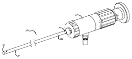
<도 1>
도 1은 본 발명의 일 실시예에 따른 선회 프리즘 내시경의 사시도.
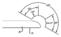
<도 2>
도 2는 본 발명의 일 실시예에 따른, 선회 프리즘을 갖춘 내시경의 관찰 범위를 도시하는 측면도.
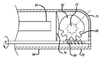
<도 3>
도 3은 본 발명의 일 실시예에 따른, 선회 프리즘 내시경의 원위 단부의 단면도.
<도 4>
도 4는 본 발명의 일 실시예에 따른, 선회 프리즘 내시경의 원위 단부의 단면도.
<도 5>
도 5는 본 발명의 다른 실시예에 따른, 선회 프리즘 내시경의 원위 단부의 단면도.
<도 6>
도 6은 본 발명의 또 다른 실시예에 따른, 선회 프리즘 내시경의 원위 단부의 단면도.
<도 7>
도 7은 내시경 샤프트의 회전 및 선회 프리즘의 회전을 제어하기 위한 회전 다이얼을 갖춘 선회 프리즘 내시경의 근위 본체 부재 또는 손잡이의 측면도.
<도 8 내지 도 10>
도 8 내지 도 10은 선회 프리즘 내시경의 손잡이에 부착될 수 있는 손잡이의 3가지 상이한 실시예들의 도면.
<도 11>
도 11은 밀봉된 챔버와, 선회 프리즘의 회전을 제어하기 위해 자석을 사용하는 구동 메커니즘을 도시하는 선회 프리즘 내시경의 손잡이의 단면도.
<도 12>
도 12는 밀봉된 챔버와, 선회 프리즘의 회전을 제어하기 위해 벨로우즈를 사용하는 구동 메커니즘을 도시하는 선회 프리즘 내시경의 손잡이의 단면도.
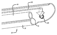
<도 13 및 도 14>
도 13 및 도 14는 선회 프리즘 내시경 위에 배치된 세척 시스템을 휴지 상태에서 도시하는 도면.
<도 15>
도 15는 도 13 및 도 14에 도시된 세척 시스템을 전진 위치 또는 활성화 상태에서 도시하는 도면.
<도 16>
도 16은 가요성 또는 조향가능한 샤프트를 갖는 전형적인 내시경의 관찰 각도를 도시하는 도면.
<도 17>
도 17은 가요성 또는 조향가능한 샤프트를 갖는 선회 프리즘 내시경의 관찰 각도를 도시하는 도면.
<도 18>
도 18은 더 넓은 조명 영역을 생성하기 위해 다양한 각도로 래핑된(lapped) 감소된 개수의 광섬유를 도시하는 도면.
<도 19>
도 19는 더 넓은 조명 빔(beam)을 생성하기 위해 광섬유의 원위 단부에 위치된 발산 렌즈를 도시하는 도면.
<도 20>
도 20은 시야를 증가시키기 위해 제1 프리즘과 제2 프리즘 및 발산 렌즈를 갖는 소형화된 내시경의 부분도.
<도 21>
도 21은 시야를 증가시키기 위해 제1 프리즘 및 발산 렌즈를 갖는 소형화된 내시경의 부분도.
<도 22>
도 22는 제1 프리즘과 제2 프리즘을 가지며, 귀환 이미지 포착 영역을 증가시키기 위해 오목 렌즈와 조합하여 발산 렌즈를 사용하는 소형화된 내시경의 부분도.
<도 23>
도 23은 제1 프리즘을 가지며, 귀환 이미지 포착 영역을 증가시키기 위해 2개의 오목 렌즈와 조합하여 발산 렌즈를 사용하는 소형화된 내시경의 부분도.
<도 24a>
도 24a는 개방 구성을 갖는 손잡이를 구비하는 내시경의 일 실시예를 도시하는 도면.
<도 24b>
도 24b는 도 24a에 도시된 내시경의 손잡이의 단면도.
<도 24c>
도 24c는 손잡이 상에 라이트 포스트(light post)가 없는 내시경의 일 실시예를 도시하는 도면.
<도 25>
도 25는 철-함유 유체 시일(seal)을 포함하는 내시경의 손잡이의 단면도.
<도 26a>
도 26a는 본 발명의 일 실시예에 따른, 사람 또는 동물 대상의 콧구멍 내로 도입된 선회 프리즘 내시경을 도시하는 도면.
<도 26b>
도 26b는 선회 프리즘이 선회 프리즘 스코프의 종축에 대해 소정 각도로 관찰하도록 조절된 상태의, 부비 해부학적 구조물 내로 더욱 전진된 도 26a의 내시경을 도시하는 도면.
<도 27a 내지 도 27d>
도 27a 내지 도 27d는 본 발명의 일 실시예에 따른, 부비동 안내체를 사용하여 부비동을 관찰하고 부비동에의 접근을 용이하게 하기 위해 선회 프리즘 스코프를 사용하는 방법의 다양한 단계를 도시하는 사람 두부를 통한 부분 시상(sagittal) 단면도.
<도 28>
도 28은 안내 시스템의 일 실시예의 사시도.
<도 29>
도 29는 사람 대상에 대한 사용시의 안내 시스템의 사시도.
<도 30a>
도 30a는 도 28의 시스템의 안내 카테터의 측면도.
<도 30b>
도 30b는 도 30a의 선 30B-30B를 통한 단면도.
<도 30c>
도 30c는 도 30a의 선 30C-30C를 통한 단면도.
<도 31>
도 31은 도 28의 시스템의 커넥터/카메라/광 케이블 조립체의 측면도.<Figure 1>
1 is a perspective view of a turning prism endoscope according to an embodiment of the present invention.
<FIG. 2>
FIG. 2 is a side view showing an observation range of an endoscope with a turning prism according to an embodiment of the present invention. FIG.
3,
3 is a cross-sectional view of the distal end of a turning prism endoscope, in accordance with an embodiment of the present invention.
<Figure 4>
4 is a cross-sectional view of the distal end of a turning prism endoscope, in accordance with an embodiment of the present invention.
<Figure 5>
5 is a cross-sectional view of the distal end of a turning prism endoscope, in accordance with another embodiment of the present invention.
6,
6 is a cross-sectional view of the distal end of a turning prism endoscope, in accordance with another embodiment of the present invention.
<Figure 7>
7 is a side view of a proximal body member or handle of a turning prism endoscope with a rotating dial for controlling rotation of the endoscope shaft and rotation of the turning prism.
8 to 10
8-10 illustrate three different embodiments of a handle that may be attached to a handle of a turning prism endoscope.
<Figure 11>
FIG. 11 is a cross-sectional view of a handle of a turning prism endoscope showing a sealed chamber and a drive mechanism using a magnet to control the rotation of the turning prism. FIG.
<Figure 12>
12 is a cross-sectional view of the handle of a turning prism endoscope showing a sealed chamber and a drive mechanism using a bellows to control the rotation of the turning prism.
13 and 14
13 and 14 show, in a resting state, a cleaning system disposed above the pivoting prism endoscope.
Figure 15
FIG. 15 shows the cleaning system shown in FIGS. 13 and 14 in an advanced position or in an activated state.
<Figure 16>
FIG. 16 shows a viewing angle of a typical endoscope with a flexible or steerable shaft. FIG.
<Figure 17>
FIG. 17 illustrates the viewing angle of a pivoting prism endoscope having a flexible or steerable shaft. FIG.
<Figure 18>
FIG. 18 illustrates a reduced number of optical fibers wrapped at various angles to create a wider illumination area.
<Figure 19>
19 shows a diverging lens located at the distal end of an optical fiber to produce a wider illumination beam.
<Figure 20>
20 is a partial view of a miniature endoscope having a first prism and a second prism and a diverging lens to increase the field of view.
Figure 21
21 is a partial view of a miniature endoscope having a first prism and diverging lens to increase the field of view.
<Figure 22>
22 is a partial view of a miniature endoscope having a first prism and a second prism and using divergence lenses in combination with concave lenses to increase the feedback image capture area.
Figure 23
FIG. 23 is a partial view of a miniature endoscope having a first prism and using divergence lenses in combination with two concave lenses to increase the feedback image capture area; FIG.
Figure 24a
24A illustrates one embodiment of an endoscope having a handle having an open configuration.
Figure 24b
24B is a cross-sectional view of the handle of the endoscope shown in FIG. 24A.
Figure 24c
FIG. 24C illustrates one embodiment of an endoscope without a light post on the handle. FIG.
<FIG. 25>
FIG. 25 is a cross sectional view of a handle of an endoscope including an iron-containing fluid seal; FIG.
<Figure 26a>
FIG. 26A illustrates a turning prism endoscope introduced into a nostril of a human or animal subject, in accordance with an embodiment of the present invention. FIG.
<Figure 26b>
FIG. 26B shows the endoscope of FIG. 26A further advanced into the paranasal anatomical structure with the pivoting prism adjusted to view at an angle to the longitudinal axis of the pivoting prism scope.
27A to 27D
27A-27D illustrate a human head showing various steps of a method of using a turning prism scope to observe the sinuses and facilitate access to the sinuses using a sinus guide according to one embodiment of the present invention. Partial sagittal cross section through.
<Figure 28>
28 is a perspective view of one embodiment of a guidance system.
<Figure 29>
29 is a perspective view of a guidance system in use for a human subject.
<FIG. 30A>
30A is a side view of the guide catheter of the system of FIG. 28.
Figure 30b
30B is a cross sectional view through
Figure 30c
30C is a cross sectional view through
Figure 31
FIG. 31 is a side view of the connector / camera / optical cable assembly of the system of FIG. 28. FIG.
다음의 설명에서, 값의 범위가 제공되는 경우에, 문맥이 명확하게 달리 지시하지 않으면, 하한의 단위의 1/10까지의 각각의 개재된 값이 그러한 범위의 상한과 하한 사이에서 또한 구체적으로 개시된다. 언급된 범위 내의 임의의 언급된 값 또는 개재된 값과 그러한 언급된 범위 내의 임의의 다른 언급된 또는 개재된 값 사이의 각각의 더 작은 범위가 본 발명 내에 포함된다. 이들 더 작은 범위의 상한 및 하한은 독립적으로 그 범위 내에 포함되거나 배제될 수 있고, 어느 하나 또는 둘 모두의 한도가 더 작은 범위 내에 포함되거나 어느 한도도 더 작은 범위 내에 포함되지 않는 각각의 범위는 언급된 범위 내의 임의의 특정적으로 배제된 한도를 조건으로 하여 본 발명 내에 또한 포함된다. 언급된 범위가 한도들 중 하나 또는 둘 모두를 포함하는 경우에, 그러한 포함된 한도들 중 어느 하나 또는 둘 모두를 배제하는 범위가 또한 본 발명에 포함된다.In the following description, where a range of values is provided, each intervening value up to one tenth of a unit of the lower limit is also specifically disclosed between the upper and lower limits of that range, unless the context clearly dictates otherwise. do. Each smaller range between any stated value or intervening value within the stated range and any other stated or intervening value within such stated range is included within the invention. The upper and lower limits of these smaller ranges may be independently included or excluded within that range, and each range in which either or both of the limits are included in the smaller range or none of the smaller ranges is mentioned. It is also included within the present invention subject to any specifically excluded limits within the scope set forth. Where the stated range includes one or both of the limits, ranges excluding either or both of such included limits are also included in the invention.
달리 정의되지 않으면, 본 명세서에서 사용된 모든 기술 및 과학 용어는 본 발명이 속하는 기술 분야의 통상의 숙련자가 일반적으로 이해하는 것과 동일한 의미를 갖는다. 본 명세서에서 기술되는 것과 유사하거나 동등한 임의의 방법 및 재료가 본 발명의 실시 또는 시험에 사용될 수 있지만, 바람직한 방법 및 재료가 이제 기술된다. 본 명세서에 언급되는 모든 간행물은 간행물이 관련하여 인용되는 방법 및/또는 재료를 개시하고 기술하기 위해 본 명세서에 참고로 포함된다.Unless defined otherwise, all technical and scientific terms used herein have the same meaning as commonly understood by one of ordinary skill in the art to which this invention belongs. Although any methods and materials similar or equivalent to those described herein can be used in the practice or testing of the present invention, the preferred methods and materials are now described. All publications mentioned herein are incorporated herein by reference to disclose and describe the methods and / or materials in which the publications are cited.
본 명세서 및 첨부된 특허청구범위에서 사용되는 바와 같이, 단수 형태(부정 관사 및 정관사)는 문맥이 명확하게 달리 지시하지 않으면, 복수의 지시 대상을 포함한다. 따라서, 예를 들어, "채널"에 대한 언급은 복수의 그러한 채널을 포함하고, "내시경"에 대한 언급은 하나 이상의 내시경 및 그의 등가물에 대한 언급을 포함하는 등등이다.As used in this specification and the appended claims, the singular forms "a" and "an" are intended to include the plural referents unless the context clearly dictates otherwise. Thus, for example, reference to "channel" includes a plurality of such channels, reference to "endoscope" includes reference to one or more endoscopes and their equivalents, and so forth.
본 명세서에서 논의되는 간행물은 본 출원의 출원일 이전의 그의 개시 내용에 대해서만 제공된다. 본 명세서 내의 어떤 것도 본 발명이 선행 발명에 의해 그러한 간행물보다 앞서는 자격을 부여받지 못한다는 인정으로서 해석되어서는 안된다. 또한, 제공되는 간행물의 날짜는 독립적으로 확인될 필요가 있을 수 있는 실제 간행 날짜와 상이할 수 있다.Publications discussed herein are provided only for their disclosure prior to the filing date of the present application. Nothing in this specification should be construed as an admission that the present invention is not entitled to antedate such publication by virtue of prior invention. In addition, the date of the publication provided may differ from the actual publication date, which may need to be independently verified.
다음의 상세한 설명, 첨부 도면, 및 전술된 도면의 간단한 설명은 본 발명의 일부(반드시 전부인 것은 아님) 예 또는 실시예를 기술하기 위해 의도된다. 이러한 상세한 설명의 내용은 어떠한 방식으로도 본 발명의 범주를 제한하지 않는다.The following detailed description, accompanying drawings, and brief description of the foregoing drawings are intended to describe some (but not necessarily all) examples or embodiments of the invention. The content of this detailed description is not intended to limit the scope of the invention in any way.
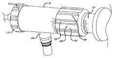
도 1은 일 실시예에 따른 가변 관찰 각도 내시경(10)을 도시한다. 내시경(10)은 원위 단부(70) 및 근위 단부(71)를 갖는 긴 샤프트(30)와, 내시경(10)의 관찰 각도를 조절하기 위한 선회 프리즘(도시되지 않음, 아래에서 도 3과 관련하여 기술됨, 이하 참조)을 포함할 수 있는데, 근위 단부는 조절가능한 스코프/로크 연장부(scope/lock extension)에 맞물리고 이에 부착되도록 구성될 수 있는 근위 본체 부재 또는 손잡이(52)에 부착된다. 샤프트(30)는 그 중심을 통해 동축으로 연장되는 이미지 섬유 다발 또는 광섬유(54)를 내장할 수 있는데, 이때 광 투과 섬유(56)가 주연부 둘레에 배치된다. 일 실시예에서, 샤프트(30)는 0.95 ㎜(0.0375 인치)의 최대 외경 및 0.61 m(2 피트)의 길이를 갖는 편조(braided) 폴리이미드 시스(sheath)일 수 있다. 바람직하게는, 이미지 섬유 다발은 10,000개의 얇은 이미지 섬유로 구성되고, 광 투과 섬유는 약 10,000의 최소 럭스(lux)를 갖는, 약 0.2 내지 약 0.51 ㎜(약 0.008 내지 약 0.020 인치) 사이의 직경을 갖는 조명 섬유이다. 다른 실시예에서, 내시경(10)은 이미지 섬유 다발을 사용하는 대신 막대 렌즈 기술을 사용할 수 있다.1 illustrates a variable
이제 도 2를 참조하면, 내시경 샤프트(30)의 원위 단부(70)가 일 실시예에 따른 각(angular) 측정과 함께 도시되어 있다. 도 2를 기술함에 있어서, "관찰 영역"은 내시경에 의해 임의의 한 시점에서 관찰되는 각 폭/높이를 의미하고, "관찰 방향"은 관찰 중심이 임의의 한 시점에서 향하는 방향을 의미하고("가변 관찰 각도 내시경"에서와 같이 "관찰 각도"로 또한 불릴 수 있음), "전체 관찰 범위"는 선회 프리즘이 하나의 극단 관찰 방향으로부터 반대편 극단 관찰 방향으로 이동될 때 내시경이 가로질러 관찰할 수 있는 전체 각 거리를 의미한다. 언급되는 각도는 0의 각도인 내시경 샤프트(30)의 종축과 관련된다.Referring now to FIG. 2, the
일부 실시예에서, 예를 들어, 내시경(10)은 약 -5° 내지 약 150°, 그리고 더 가능하게는 약 0° 내지 약 120° 또는 약 5° 내지 약 100°의 관찰 방향의 범위를 가질 수 있다. 일부 실시예에서, 내시경은 약 50° 내지 약 100° 또는 더 가능하게는 약 60° 내지 약 70°의 관찰 영역을 가질 수 있다. 관찰 방향 및 관찰 영역의 범위로부터, 전체 관찰 범위가 결정될 수 있다. 예를 들어, 일 실시예에서, 내시경(10)은 약 5° 내지 약 100° 범위의 관찰 방향을 가질 수 있고, 약 60°의 관찰 영역을 가질 수 있다. 이러한 실시예에서, 전체 관찰 범위는 약 -25° 내지 약 130°일 것이다. 관찰 방향의 범위가 대신에 약 0° 내지 약 120°이고, 관찰 영역이 약 60°이면, 전체 관찰 범위는 약 -30° 내지 약 150°일 것이다. 다양한 실시예에서, 내시경(10)은 관찰 방향, 관찰 영역, 및 전체 관찰 범위의 다수의 상이한 조합 및 범위 중 임의의 것을 가질 수 있다.In some embodiments, for example,
이제 도 3 내지 도 6을 참조하면, 가변 관찰 각도 내시경(10)의 다양한 구성의 원위부(70)들이 도시되어 있고, 각각은 선회 프리즘(72) 및/또는 선회 프리즘(72)을 장착하기 위한 메커니즘의 상이한 구성을 갖는다. 제1 접근에서, 선회 프리즘(72)은 편의 스프링(biasing spring, 76)과 액추에이터(78) 사이에서 회전하도록 장착된다. 여기서, 액추에이터(78)는 내시경(10)의 원위부(70)로부터, 작업자에 의해 편리하게 접근가능하고 조작가능한 근위부로 연장되는 와이어 형태로 될 수 있다. 이 점에 있어서, 액추에이터는 활주 부재에 부착될 수 있거나, 회전 다이얼(도시되지 않음)에 의해 권취되도록 구성될 수 있다. 그렇게 구성된 때, 이미지가 창(window, 75)을 통해 포착되고 수신되어, 선회 프리즘(72) 및 자동 초점 렌즈(74)를 통해 이미지 섬유 다발(54)로 전달될 수 있다. 선회 프리즘(72)은 액추에이터(78)를 조작함으로써 0도 내지 95도의 관찰 범위 전체에 걸쳐 원하는 70도의 관찰 영역을 제공한다.Referring now to FIGS. 3-6,
도 4에 도시된 다른 접근에서, 선회 프리즘(72)은 근위방향으로 조작자에게로 연장되는 회전가능 샤프트(84)와 작동식으로 연관되어 배치된 하우징(82) 내에 장착될 수 있다. 샤프트(84)의 원위부에는 하우징(82) 상에 형성된 치형부(88)와 맞물리도록 배열된 나사 구조물(86)이 구비된다. 샤프트를 회전시키는 것은 선회 프리즘(72)을 원하는 대로 위치시키는 것을 달성한다. 다시, 이들 구성요소는 165도의 관찰 범위를 제공하도록 배열될 수 있다.In another approach shown in FIG. 4, the pivoting
도 5에 도시된 또 다른 접근에서, 선회 프리즘(72)은 근위방향으로 조작자에게로 연장되는 치형부(94)를 포함하는 평탄 바아(92)와 작동식으로 연관되어 배치된 하우징(90) 내에 장착될 수 있다. 하우징(90)은 내시경 샤프트(30)의 원위 단부(70)에 부착된 핀(도시되지 않음) 상에 장착될 수 있고, 이때 하우징과 선회 프리즘은 핀을 중심으로 피벗한다. 또한, 평탄 바아 상의 치형부(94)와 맞물리는 치형부(98)가 하우징 상에 있다. 평탄 바아를 근위 또는 원위 방향으로 이동시키는 것은 선회 프리즘(72)을 원하는 대로 위치시키는 것을 달성한다. 다시, 이들 구성요소는 165도의 관찰 범위를 제공하도록 배열될 수 있다.In another approach shown in FIG. 5, the pivoting
도 6에 도시된 접근에서, 선회 프리즘(72)은 비틀림 스프링(100)과 당김 와이어(102) 사이에서 회전하도록 장착된다. 비틀림 스프링은 인장 스프링, 판 스프링 등과 같은 임의의 스프링일 수 있다. 여기서, 당김 와이어(102)는 내시경 샤프트(30)의 원위부(70)로부터, 조작자에 의해 편리하게 접근가능하고 조작가능한 근위부로 연장될 수 있다. 이 점에 있어서, 당김 와이어는 활주 부재에 부착될 수 있거나, 회전 다이얼에 의해 권취되도록 구성될 수 있다. 이미지가 창(도시되지 않음)을 통해 포착되고 수신되어, 선회 프리즘(72) 및 자동 초점 렌즈(74)를 통해 이미지 섬유 다발(54)로 전달될 수 있다. 이러한 실시예에서, 비틀림 스프링과 당김 와이어 사이의 선회 프리즘에 장력이 항상 있고, 따라서 작동 동안에 당김 와이어에 처짐 또는 좌굴이 없다. 또한, 선회 프리즘을 이동시키기 위한 당김 와이어 및 비틀림 스프링의 사용은 내시경의 직경이 더 작아질 수 있게 한다.In the approach shown in FIG. 6, the turning
이미지 섬유 다발(54)에 의해 수집된 이미지는 모니터(후술됨)로 전달되어, 수행되고 있는 특정 개입 시술에 관한 시각적 데이터를 조작자에게 제공할 수 있다. 일 실시예에서, 내시경(10)은 300 와트 제논 광원과 함께 상용가능하고 범용 도광 커넥터(universal light guide connector)를 사용하여 구성되어서, 조립체를 종래에 이용가능한 장치와 함께 사용가능하게 만든다. 일 실시예에서, 내시경 샤프트(30)는 대략 4 ㎜의 외경 및 약 175 ㎜의 작동 길이를 가질 수 있다. 또한, 내시경 샤프트(30)에는 바람직하게는 둥근 표면이 구비되어, 조립체가 사용시에 외상을 초래하지 않게 만든다. 내시경(10)이 가압멸균기를 사용하여 멸균되게 하는 방식으로 그리고 그러한 재료를 채용하여 내시경(10)을 구성하는 것이 유용하다고 또한 밝혀졌다.The image collected by the
소정의 접근에서, 선회 프리즘의 관찰 방향 및/또는 내시경(10)의 회전 위치를 표시하는 표지(indicia)를 갖는 내시경(10)을 구성하는 것이 유용할 수 있다. 따라서, 도 3의 액추에이터(78)의 근위부는, 예를 들어, 선회 프리즘(72)의 각도를 나타내는 마킹(marking)을 포함하는 다이얼과 결합될 수 있다. 유사하게, 도 4의 샤프트(84)의 근위 단부는 선회 프리즘(72)의 각도에 대한 정보를 제공하는 표지를 포함하는 다이얼에 부착될 수 있다. 또한, 내시경(10)의 외부 표면은 전체 조립체의 회전 위치설정을 나타내는 마킹 표시기를 포함할 수 있다.In certain approaches, it may be useful to construct an
선회 프리즘 내시경(10)은 부비동 안내체와 함께 해부학적 구조물 내에서 자유롭게 전진될 수 있어, 원하는 해부학적 구조물의 내시경 관찰을 용이하게 하고/하거나 부비동 안내 장치의 위치설정 또는 부비동 안내체를 통해 삽입된 작동 장치의 위치설정을 관찰, 안내, 및/또는 검증하도록 한다. 부비동 안내체의 단부를 관찰하기 위해 해부학적 구조물 내에서 내시경(10)의 팁을 전진시키는 능력은 장치가 해부학적 구조물에 더 가까이 위치되게 하거나 크기 제한으로 인해 장치가 이동할 수 없는 부비동 내의 공간에 도달하게 한다.The pivoting
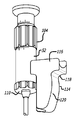
도 3 내지 도 6을 참조하여 위에서 논의된 바와 같이, 선회 프리즘의 회전은 다이얼에 의해 제어될 수 있다. 도 7에 도시된 바와 같이, 선회 프리즘의 회전을 제어하기 위해 내시경(10)의 손잡이(52) 상에 근위 다이얼(104)이 배치된다. 근위 다이얼(104)은 원형 구성을 갖고, 근위 다이얼 또는 다이얼을 원하는 위치로 돌리기 위한 지레 작용(leverage)을 제공하는 리지(ridge, 106)를 포함한다. 또한, 리지는 다이얼 위치에 대한 촉각적 느낌을 제공하고, 리지들 사이의 홈(108)은 사용자의 손가락이 놓이는 영역을 제공한다. 일 실시예에서, 근위 다이얼(104) 둘레에 균등하게 위치된 8개의 리지가 있지만, 다이얼 둘레에 위치된 더 적거나 더 많은 리지가 있을 수 있다. 리지의 높이는 대략 1.27 ㎜(0.05 인치)이고, 사용자 선호도에 따라 증가 또는 감소될 수 있다. 또한, 각각의 리지 사이의 간격은 대략 5.79 ㎜(0.228 인치)이고, 다이얼 상에 배치된 리지의 개수 및 리지의 폭에 따라 증가 또는 감소될 수 있다.As discussed above with reference to FIGS. 3-6, the rotation of the turning prism can be controlled by the dial. As shown in FIG. 7, a
여전히 도 7을 참조하면, 내시경의 손잡이(52)는 선회 프리즘(72)의 각도에 대한 정보를 제공하기 위해 근위 다이얼(104)에 인접한 표지(107)를 포함할 수 있다. 이러한 실시예에서, 선회 프리즘(72)의 상대 각도를 자체적으로 표시하는 근위 다이얼 상의 마커(marker, 108)가 또한 있다. 도시된 바와 같이, 근위 다이얼에 인접한 표지(107)는 0°에서 180°까지 어디서나 선회 프리즘(72)의 상대 각도를 표시한다.Still referring to FIG. 7, the
일 실시예에서, 원위 다이얼 또는 샤프트 다이얼(110)이 도 7에 도시된 바와 같이 내시경의 손잡이(52) 상에 배치되고, 샤프트 다이얼(110)은 내시경 샤프트(30)의 회전을 제어한다. 내시경 샤프트(30)의 상대 위치를 표시하기 위한 마커(112)가 샤프트 다이얼(110) 상에 나타나 있다. 더 구체적으로, 샤프트 다이얼 상의 마커(112)는 내시경(10)의 원위부(70)에서의 창(75)(도 3 참조)의 상대 위치를 표시한다. 도 7에 도시된 바와 같이, 마커(112)가 내시경의 상부 면 상에 있으므로, 창(75)은 또한 내시경(10)의 상부 면을 향하여 있어, 내시경(10)이 동일한 전반적인 방향으로 주위를 관찰하게 한다. 샤프트 다이얼(110)을 회전시키는 것은 내시경이 완전한 360도 회전으로 그의 주위를 관찰하게 한다. 손잡이(52) 전체를 회전시키지 않고서 내시경 샤프트(30)를 회전시키는 회전식 샤프트 다이얼(110)을 갖는 것은 라이트 포스트(109)를 회전시키지 않고서 내시경 샤프트(30)의 회전을 허용하기 때문에 유리할 수 있다.In one embodiment, a distal dial or
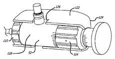
도 8은 내시경(10)의 손잡이(52)에 부착된 손잡이 부착체(114)를 도시한다. 손잡이 부착체(114)는 사용자가 내시경(10)을 파지하고 있는 동안에 다이얼(104, 110)을 돌리는 것을 용이하게 한다. 손잡이 부착체(114)는 손잡이(52)에 고정되고/되거나 손잡이(52)로부터 유래한 라이트 포스트(109) 상으로 스냅 끼워맞춤될 수 있다. 손잡이 부착체(114)의 라이트 포스트 부분(116)이 라이트 포스트(109) 상으로 스냅되어, 사용자를 라이트 포스트(109)로부터 방사되는 열로부터 차폐한다. 손잡이 부착체(114) 및 내시경(10)을 파지하고 있는 동안에, 사용자의 엄지 손가락과 뻗은 검지 손가락 사이의 굴곡부는 손잡이의 라이트 포스트 부분(116) 아래의 만곡부(118)에 위치되는 반면, 사용자의 손의 손바닥은 손잡이 부착체(114)의 본체(120) 상에 놓인다. 손잡이 부착체(114)는 내시경을 파지하고 있는 동안에 사용자에게 편안함 및 균형을 제공할 수 있고, 또한 다이얼(104, 110)을 돌리는 추가의 토크(torque)를 제공할 수 있다. 손잡이 부착체(114)를 사용하여 내시경(10)을 파지하는 것은 사용자가 엄지 및 검지 손가락으로 근위 다이얼(104)을 돌리게 하고, 원위 다이얼(110)은 약손가락 또는 새끼 손가락에 의해 접근될 수 있다.8 shows a
내시경의 손잡이(52) 상으로 스냅 끼워맞춤되는 랩어라운드(wrap-around) 손잡이 부착체(122)의 다른 실시예가 도 9에 도시되어 있다. 랩어라운드 손잡이 부착체(122)는 사용자가 다이얼(104, 110)의 회전에 영향을 주지 않으면서 내시경을 단단히 파지하게 한다. 손잡이 부착체 배면(124)은 사용자의 손바닥 내의 다양한 위치에 맞도록 둥글게 그리고 상대적으로 길게 설계된다. 라이트 포스트 절결부(126)에 의해, 손잡이 부착체(122)는 사용자가 다양하게 파지하는 것을 용이하게 하도록 약 270도로 손잡이(52) 둘레에서 이동되거나 위치될 수 있다. 손잡이 부착체(122)는 손잡이 부착체(122)가 다이얼(104, 110)에 대한 접근을 여전히 허용하면서 내시경(10)의 다이얼 및 손잡이(52)와 절반 초과로 중첩하게 하는 개방부(128)를 포함한다.Another embodiment of a wrap-around
내시경(10)의 손잡이(52) 상으로 스냅 끼워맞춤되는 다리(leg, 132)를 포함하는, 손잡이 부착체(130)의 또 다른 실시예가 도 10에 도시되어 있다. 손잡이 부착체(130)는 사용자의 손바닥에 대해 맞는 배면(134), 및 근위 다이얼(104) 위에서 연장하는 다이얼 커버(136)를 포함한다. 라이트 포스트(109)를 수용하기 위한 라이트 포스트 슬롯(138)을 또한 도 10에서 볼 수 있다. 사용자는 손잡이(130)에 의해 내시경(10)을 파지할 때 다이얼(104, 110)이 그의 손가락과 자유롭게 맞닿게 허용된다.Another embodiment of the handle attachment 130 is shown in FIG. 10, including a
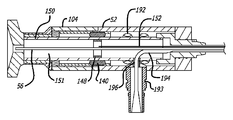
내시경(10)의 광섬유(54)는 내시경이 가압멸균되게 하도록 밀봉된 챔버 내에 수납될 수 있다. 도 11에 도시된 일 실시예에서, 하우징(142)에 부착된 외측 자석(140)은 나사 메커니즘을 구동하는 근위 다이얼(104)에 의해 종방향 운동에 있어서 제어된다. 핀(144)이 근위 다이얼(104)에 부착되고, 손잡이(52) 내로 그리고 만곡형 슬롯(146)을 통해 연장된다. 만곡형 슬롯은 하우징(142) 둘레에서 나선형일 수 있다. 근위 다이얼(104)이 돌려짐에 따라, 핀은 만곡형 슬롯을 따라 이동하여, 하우징(142)을 내시경의 종축을 따라 근위 또는 원위 방향으로 이동시킨다. 외측 자석이 전방 및 후방으로 이동할 때, 외측 자석은 외측 자석과 반대 전하를 갖는 내측 자석(148)을 구동한다. 내측 자석은 광섬유를 위한 밀봉된 챔버(151)를 생성하는 내측 차폐체(150) 내에 배치된다. 내측 자석은 또한 내시경의 원위 단부에서 선회 프리즘을 회전시키는 푸시/풀(push/pull) 메커니즘(152)에 부착된다. 푸시/풀 메커니즘은 선회 프리즘에 부착되는, 액추에이터, 당김 와이어, 바아, 하이포튜브(hypotube) 등일 수 있다. 내측 자석이 외측 자석의 이동에 의해 전방 또는 후방으로 구동될 때, 내측 자석은 회전가능한 프리즘을 위한 구동기 또는 푸시/풀 메커니즘을 밀거나 당긴다.The
도 12에 도시된 다른 실시예에서, 중간 벨로우즈 조인트(154)가 하우징(142)에 부착되고, 도 11에 도시된 실시예와 유사한 나사 메커니즘을 구동하는 근위 다이얼(104)에 의해 종방향 운동에 있어서 제어된다. 근위 다이얼에 부착된 핀(144)은 손잡이(52) 내로 그리고 하우징(142) 내에 배치된 만곡형 슬롯을 통해 연장된다. 내측 차폐부(160) 상에서 내시경 내에 고정된 근위 벨로우즈 조인트(156) 및 원위 벨로우즈 조인트(158)가 또한 있고, 벨로우즈 조인트(154, 156, 158)들 사이에 배치된 가요성 벨로우즈(162)가 있다. 근위 다이얼(104)이 돌려짐에 따라, 핀은 만곡형 슬롯을 따라 이동하여, 하우징(142)을 내시경의 종축을 따라 근위 또는 원위 방향으로 이동시키고 중간 벨로우즈 조인트를 이동시킨다. 중간 벨로우즈 조인트가 전방 및 후방으로 이동할 때, 중간 벨로우즈 조인트는 중간 벨로우즈 조인트에 부착된 푸시/풀 메커니즘(152)을 이동시킴으로써 선회 프리즘을 구동한다. 내측 차폐체(160)는 광섬유(54)를 위한 밀봉된 챔버(151)를 생성한다. 푸시/풀 메커니즘은 선회 프리즘에 부착되는, 액추에이터, 당김 와이어, 바아, 하이포튜브 등일 수 있다. 이러한 실시예에서, 벨로우즈 조인트는 중간 벨로우즈 조인트(154)에 부착될 수 있는 하이포튜브 또는 회전가능한 샤프트의 회전을 위한 토크를 쉽게 전달할 수 있다.In another embodiment shown in FIG. 12, an intermediate bellows joint 154 is attached to the
일 실시예에서, 내시경(10)은 재사용가능한 기구이다. 통상적으로, 내시경은 스테리스(steris), 가압멸균기 또는 다른 공지된 공정에 의해 사용들 사이에서 처리된다. 내시경을 처리하기 위해 요구되는 시간은 중요할 수 있는데, 이는 환자들 사이에서의 지연 또는 차례로 발생하는 시술들을 위해 다수의 내시경을 구매할 필요성을 초래한다. 일 실시예는 내시경(10)과 함께 사용되는 일회용 멸균 슬리브(164)(도 1 참조)를 포함한다. 멸균 슬리브는 프로파일이 낮고, 프리즘에 의한 관찰을 허용하도록 원위 팁에서 광학적으로 투명하다. 멸균 슬리브는 시술을 위해 환자 내로 삽입된 내시경의 전체 길이에 걸쳐 있어서, 환자와 내시경 사이의 직접적인 접촉이 없도록 한다. 또한, 멸균 슬리브는 내시경 및 카메라의 근위 단부를 덮을 수 있어서, 사용자와 내시경 사이의 직접적인 접촉이 없도록 한다. 일단 시술이 완료되면, 사용자는 단순히 멸균 슬리브를 제거하여 폐기하고, 이어서 다음 환자를 위해 내시경 위로 새로운 멸균 슬리브를 삽입한다. 멸균 슬리브의 사용은 환자들 사이에서 또는 사무실 환경에서 내시경을 처리할 필요성을 제거할 수 있다.In one embodiment, the
환자 시술 동안에, 내시경은 내시경의 원위 팁에 부착되는 찌꺼기, 혈액, 및/또는 점액 때문에 시각적 명료성을 상실하는 경향을 갖는다. 통상적으로, 외과 의사 또는 사용자는 내시경의 원위 팁을 세정하기 위해 빈번하게 환자로부터 내시경을 제거한다. 대안적으로, 일부 외과 의사는 원위치(in situ) 세정을 가능케 하기 위해 유체 및/또는 진공을 전달하도록 내시경 샤프트 위에서 개방 시스를 갖는 내시경 세척 시스템을 사용한다. 각각의 세척 시스는 내시경 기하학적 형상에 대해 특수하게 설계되며, 내시경 원위 팁의 기하학적 형상이 관찰 각도에 의해 변하기 때문에, 대응하여 사용되어야 하는 다수의 세정 시스가 또한 있다. 따라서, 사용자가 시술 동안에 내시경 관찰 각도를 변화시키기를 원할 때, 세척 시스가 또한 변경되어야 한다. 후술되는 일 실시예에서, 세척 시스템 및 시스가 내시경(10)에 사용된다. 전술된 바와 같이, 내시경(10)의 기하학적 형상은 원하는 관찰의 방향이 변화할 때 변화되지 않으며, 따라서 단일의 고정된 시스가 본 명세서에서 기술되는 선회 프리즘 내시경에 사용될 수 있다.During patient procedures, the endoscope tends to lose visual clarity due to debris, blood, and / or mucus attached to the distal tip of the endoscope. Typically, the surgeon or user frequently removes the endoscope from the patient to clean the distal tip of the endoscope. Alternatively, some surgeons use an endoscopic cleaning system with an open sheath on the endoscope shaft to deliver fluid and / or vacuum to enable in situ cleaning. Each cleaning sheath is specially designed for the endoscope geometry, and there are also a number of cleaning sheaths that must be used correspondingly because the geometry of the endoscope distal tip varies with the viewing angle. Thus, when the user wants to change the endoscope viewing angle during the procedure, the cleaning sheath must also be changed. In one embodiment described below, cleaning systems and sheaths are used in the
세척 시스템(168)이 도 13 내지 도 15에서 내시경(10) 상에 배치되어 도시되어 있다. 세척 시스템은 제1 및 제2 원추부(172, 174)들 사이에 위치된 버튼(170)을 포함한다. 제1 및 제2 원추부(172, 174)는 스프링(176)(도 14)에 의해 함께 연결된다. 이러한 실시예에서, 제1 원추부(172)는 내시경에 고정되고, 제2 원추부(174)는 와이핑(wiping) 시스(178)에 연결된다. 와이핑 시스의 원위 단부는 친수성 탄성중합체일 수 있는 천(cloth, 180)을 포함한다. 도 13 및 도 14에 도시된 바와 같이, 세척 시스템(168)은 그의 휴지 상태에 있는데, 이때 인장 스프링(176)은 당겨진 상태에 있고, 제1 및 제2 원추부들은 서로로부터 최소 거리에 있다. 휴지 상태에서, 천(180)은 도 13에 도시된 바와 같이 내시경의 렌즈(75)에 대해 근위에 위치된다.The
내시경의 렌즈(75)를 세정하기 위해 세척 시스템(168)을 전방으로 이동시키기 위해, 버튼(170)이 눌러져, 버튼이 내시경의 중심 축을 벗어나서 임의의 방향으로 이동하도록 한다. 버튼의 이러한 이동은 제1 원추부(172)가 내시경에 고정되어 있으므로, 제2 원추부(174)가 전방으로 이동하게 한다. 제2 원추부(174)를 전방으로 또는 원위방향으로 구동하는 것은, 와이핑 시스(178)가 제2 원추부에 부착되어 있으므로, 와이핑 시스가 또한 전방으로 이동하게 하여 천(180)을 렌즈(75) 위로 밀게 한다. 세척 시스템의 활성화된 상태가 도 15에 도시되어 있다. 천(180)은 탄성중합체이고, 따라서 천은 렌즈(75)의 형상에 일치하게 되고, 렌즈로부터 임의의 찌꺼기, 점액, 및/또는 혈액을 닦아낸다. 다공성 친수성 천은 또한 렌즈 상에 수집된 임의의 유체를 흡수한다. 일단 버튼(170)이 해제되면, 스프링이 수축하여, 천을 렌즈 위에서 렌즈에 대해 근위인 위치로 다시 끌어당긴다.To move the
일 실시예에서, 천(180)은 천이 원위 방향으로 전방으로 밀릴 때, 천이 뭉치거나 접히는 것을 방지하기 위해, 막대, 메시(mesh) 등과 같은 지지 구조물을 가질 수 있다. 또한, 천(180)의 선단 원위 에지가 렌즈(75)로부터 전방으로(원위방향으로) 유체를 닦아내기 위한 실리콘, 고무, 또는 일부 다른 친수성 재료일 수 있음이 고려되었다. 천의 선단 원위 에지는 또한 렌즈로부터 찌꺼기를 닦아내거나 밀어내는 것을 돕기 위해 다수의 슬릿이 내부로 절단될 수 있다.In one embodiment, the
전술된 실시예에서, 내시경(10)은 상대적으로 강성인 샤프트를 가질 수 있다. 그러나, 내시경(10)의 샤프트가 또한 내시경의 관찰 영역을 크게 향상시키기 위해 가요성일 수 있음이 고려되었다. 도 16에 도시된 바와 같이, 전형적인 내시경의 가요성 범위 내의 임의의 위치에서 고정 영역(A 또는 B)을 시각화할 수 있는 전형적인 내시경이 도시되어 있다. 도 17에 도시된 본 발명의 일 실시예는 내시경(10) 내의 선회 프리즘의 굽힘 또는 위치를 수정함으로써 훨씬 더 큰 범위(A' 또는 B')를 시각화할 수 있다. 가요성 내시경이 섬유 스코프 또는 비디오 칩 기술에 의해 구성될 수 있음이 고려된다. 그러한 가요성 내시경은 가변적이고 큰 관찰 범위가 요구되는 비강내, 부비동내, 두개골 저부, 후두, 정형외과적, 복부, 및 다른 수술들에 대해 유용할 수 있다.In the embodiments described above, the
일 실시예에서, 내시경(10)은 내시경의 샤프트를 따라 이미지를 획득하고 전달하기 위해 막대 렌즈 기술을 사용한다. 다른 실시예에서, 당업계에서 이해되는 바와 같은 비디오 칩 기술은 내시경의 원위부 둘레에서 강성을 요구하고, 이미지는 내시경의 샤프트가 소형화될 수 있게 하는 와이어를 거쳐 전달된다. 비디오 칩 기술에 의한 이미지의 획득은 또한, 사용자에 의해 관찰되는 이미지의 품질 또는 이미지의 크기를 훼손하지 않으면서, 내시경의 원위부의 직경이 소형화되게 할 수 있다. 현재의 비디오 칩 기술은 내시경의 원위 단부가 약 1.2 ㎜ 내지 약 1.8 ㎜의 최소 직경을 가질 것을 요구한다. 조명 섬유 및 선회 프리즘을 위한 기구의 추가에 의해, 비디오 칩 기술을 사용하는 내시경은 4 ㎜ 미만의 내시경의 원위부에서의 직경으로 구성될 수 있다.In one embodiment,
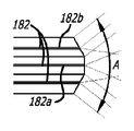
선회 프리즘 내시경과 같은 내시경을 소형화한 후에, 조명 영역을 증가시키고 이미지 포착 영역을 증가시키는 소정의 실시예가 본 명세서에서 개시된다. 내시경이 크기가 감소되거나 소형화될 때, 광섬유의 개수는 감소되고, 이에 의해 그러한 광섬유를 이용하는 조명 영역을 감소시킨다. 또한, 내시경을 소형화하는 것은 귀환 이미지를 위한 광학 구성요소의 보다 작은 크기로 인해 이미지 포착 영역을 감소시킨다. 도 18에 도시된 바와 같이, 소형화된 내시경의 일 실시예는 약 0도 내지 약 30도의 다양한 각도로 래핑된 광섬유(182)들을 포함한다. 이러한 실시예에서, 광섬유들은 그러한 각도들이 선택된 내부 섬유(182a)로부터 외측 또는 에지 섬유(182b)까지 증가하는 상태로 배열될 수 있고, 이에 의해 더 넓은 조명 영역(A)을 생성한다.After miniaturizing an endoscope, such as a turning prism endoscope, certain embodiments are described herein that increase the illumination area and increase the image capture area. When the endoscope is reduced in size or downsized, the number of optical fibers is reduced, thereby reducing the illumination area utilizing such optical fibers. In addition, miniaturizing the endoscope reduces the image capture area due to the smaller size of the optical components for the feedback image. As shown in FIG. 18, one embodiment of a miniaturized endoscope includes
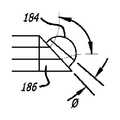
도 19에 도시된 다른 실시예에서, 발산 렌즈(184)가 더 넓은 조명 빔(B)을 생성하기 위해 광섬유(182)의 단부에 배치될 수 있다. 이러한 실시예에서, 광섬유는 약 0도로 래핑되지만, 발산 렌즈는 조명 빔의 발산을 증폭시키기 위해 도 18에 도시된 것과 유사한 래핑된 광섬유와 조합될 수 있다. 발산 또는 확장 렌즈는 빔 발산을 위해 요구되는 곡률을 갖는 유리 블록으로부터 제조되고, 이어서 에지 결함을 최소화하기 위해 톱 또는 고압 워터 제트(water jet)를 사용함으로써 분할될 수 있다. 개별 발산 렌즈의 비기능성 면은 니켈 또는 금으로 코팅되어 내부 반사 표면을 생성함으로써 광학 누출을 감소시킬 수 있다. 소형화된 내시경의 광섬유로의 입력 파워가 표준 내시경의 조명 강도와 부합하도록 증가될 수 있음을 알아야 한다.In another embodiment shown in FIG. 19, a diverging
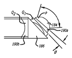
프리즘을 통한 귀환 빔에 의해 포착되는 관찰 영역을 유지 또는 개선하기 위해, 소형화된 내시경 상에 발산 렌즈가 사용될 수 있다. 도 20에 도시된 바와 같이, 소형화된 내시경은 제1 프리즘(186) 및 제1 프리즘과 접촉하는 제2 프리즘(188)을 포함한다. 관찰 영역(C)을 증가시키는 제2 프리즘(188) 상에 배치된 발산 렌즈(184)가 또한 있다. 도 21은 제1 프리즘(186)만이 사용되고 발산 렌즈(184)가 제1 프리즘 부근에 배치된 소형화된 내시경을 도시한다. 도 21에 도시된 바와 같이, Ø는 내시경의 축에 대한 귀환 빔에 대하여 최적화될 수 있다.In order to maintain or improve the viewing area captured by the return beam through the prism, a diverging lens can be used on the miniaturized endoscope. As shown in FIG. 20, the miniaturized endoscope includes a
다른 실시예에서, 귀환 광학계를 위한 귀환 이미지 포착 영역을 증가시키기 위해 오목 또는 음의 굴절력 렌즈가 원위 프리즘(186)에 장착될 수 있다. 도 22에 도시된 바와 같이, 음의 굴절력 렌즈 또는 오목 렌즈(190)는 이미지 품질을 증가시키기 위해 광섬유 상에서 수차를 최소화하면서 더 넓은 이미지 포착 각도를 달성하도록 양의 굴절력 렌즈 또는 발산 렌즈(184)와 조합하여 사용된다. 이러한 실시예에서, 프리즘을 위한 조향 메커니즘은 광각 이미지의 범위가 프리즘을 조향하지 않고서 목표 영역을 담당하기에 충분하다면 제거될 수 있다. 조향 메커니즘이 제거된 실시예에서, 이는 목표 영역을 보다 양호하게 조명하고 신뢰성을 개선하기 위해 더 많은 조명 광섬유를 추가하기 위한 소형화된 내시경 내의 더 많은 공간을 생성할 것이다.In another embodiment, a concave or negative refractive power lens may be mounted to the
도 23에 도시된 다른 실시예에서, 2개의 음의 굴절력 렌즈가 프리즘 조향 메커니즘을 포함하는 소형화된 내시경의 단일 프리즘에 사용된다. 도 23에 도시된 바와 같이, 제1 음의 굴절력 렌즈 또는 오목 렌즈(190a)가 프리즘(186)의 원위에 배치되고, 제2 음의 굴절력 렌즈 또는 오목 렌즈(190b)가 프리즘(186)의 근위에 배치된다. 이러한 실시예에서, 제1 및 제2 오목 렌즈들은 요구되는 대로 서로 연관되거나 개별적으로 작동할 수 있다. 또한, 양의 굴절력 렌즈 또는 발산 렌즈(184)는 제1 오목 렌즈(190a)의 원위에 위치된다. 발산 렌즈(184)는 렌즈 시스템 내의 광학 수차를 감소시키고 이미지 품질을 향상시키기 위해 제1 및 제2 오목 렌즈(190a, 190b)들과 함께 작동한다.In another embodiment, shown in FIG. 23, two negative refractive power lenses are used for a single prism of a miniature endoscope that includes a prism steering mechanism. As shown in FIG. 23, a first negative refractive power lens or
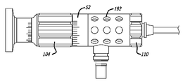
이제 도 24a 및 도 24b를 참조하면, 내시경의 손잡이(52)의 일 실시예는 유체가 손잡이(52) 내외로 자유롭게 이동하게 하도록 개방될 수 있다. 이러한 방식으로, 내시경의 손잡이(52)는 밀봉된 챔버(151)(도 11 또는 도 24b 참조)가 밀봉 상태로 유지되는 동안 세정되고 건조될 수 있다. 일 실시예에서, 근위 본체(52)는 손잡이(52)의 하우징 내로 구멍(192)을 천공함으로써 개방 구성을 갖는다. 다른 실시예에서, 개방 손잡이(52)를 생성하기 위해 메시(mesh)가 사용될 수 있다. 개방 구성이 없으면, 유체가 파손된 시일을 통해 손잡이(52)의 내측 챔버 내로 누출될 가능성이 있다. 손잡이(52)의 내측 챔버로 진입한 임의의 유체는 구성요소를 부식시키고 박테리아 성장을 허용할 잠재성을 갖는다. 따라서, 손잡이(52)에 개방 구성을 제공하는 것은, 진입한 임의의 유체가 구멍(192)을 통해 더 쉽게 증발하거나 배수될 것이기 때문에, 손잡이의 내측 챔버 내에서 이러한 문제점을 방지한다.Referring now to FIGS. 24A and 24B, one embodiment of the
도 24b에 도시된 내시경의 손잡이(52)는 도 11에 도시된 실시예와 유사한데, 여기서 푸시/풀 메커니즘(152)은 위에서 논의된 바와 같이 외측 자석(140) 및 내측 자석(148)에 의해 제어되고, 내측 자석은 광섬유(54)를 위한 밀봉된 챔버(151)를 생성하는 내측 차폐체(150) 내에 배치된다. 라이트 포스트(193)로부터 밀봉된 챔버(151) 또는 광학 챔버 내로 연장되는 광섬유(194)가 또한 도 24b에 도시되어 있다. 이러한 실시예에서, 광섬유는 내시경 샤프트가 라이트 포스트에 대해 회전하게 하도록 자유롭게 이동하여야 한다. 밀봉된 챔버(151)에서 시일을 유지하기 위해, 가요성 시스(196)가 광섬유(194)를 덮고, 밀봉된 챔버에 고정된다. 이러한 가요성 시스는 실리콘 또는 강철로 형성될 수 있다. 가요성 시스(196)는 광섬유가 이동하도록 허용하고, 가요성 시스는 광섬유를 손상으로부터 보호한다.The endoscope handle 52 shown in FIG. 24B is similar to the embodiment shown in FIG. 11, where the push /
도 24c에 도시된 다른 실시예에서, 도 24b에 도시된 바와 같은 라이트 포스트는 제거되었고, 가요성 시스(196) 내의 광섬유(194)가 손잡이(52)를 빠져나간다. 이러한 실시예에서, 광섬유는 내시경으로부터 더 멀리 광 케이블에 연결될 것이다. 라이트 포스트를 제거하는 것은 사용자가 내시경을 쥐게 되는 손잡이 상에서의 열 축적을 방지한다.In another embodiment shown in FIG. 24C, the light post as shown in FIG. 24B has been removed and the
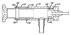
내시경의 또 다른 실시예가 도 25에 도시되어 있는데, 여기서 내시경의 내부 메커니즘은 외부 환경으로부터 밀봉된다. 도 25는 명료함을 위해 내부 구동 메커니즘이 제거된 상태로 내시경(10)의 손잡이(52)의 단면도를 도시한다. 이러한 실시예에서, 내부에 혼합된 철 입자를 함유하는 오일일 수 있는 철 함유 유체가 다이얼(104, 110)과 손잡이(52)의 내부 사이의 공간(198) 내로 주입된다. 치형부(199)가 도 25에 도시된 바와 같이 철 함유 유체를 포획하기 위해 다이얼(104, 110)의 표면 상에 형성된다. 치형부가 손잡이의 내부 표면 상에 형성될 수 있음이 또한 고려되었다. 다이얼(104, 110) 또는 손잡이(52)는 공간(198) 부근에 배치되거나 공간을 형성하는 자석을 포함할 수 있고, 이들 자석은 자성 철 함유 유체를 끌어당겨서 그와 결합할 수 있다. 다른 실시예에서, 다이얼 및 손잡이 둘 모두는 공간(198)에서 자석을 포함할 수 있다. 도 25에 도시된 바와 같이, 원위 다이얼(110) 상의 치형부는 내시경의 샤프트와 연결되어 손잡이의 내부 챔버 내에 위치된 다이얼의 근위부 상에 형성된다. 따라서, 손잡이의 내부 원주부 둘레에 형성된 공간은 유체 시일이 된다.Another embodiment of an endoscope is shown in FIG. 25, wherein the internal mechanism of the endoscope is sealed from the external environment. 25 shows a cross-sectional view of the
다이얼(104, 110) 또는 손잡이(52) 내의 자석과 철 함유 유체 사이의 이러한 결합은 마찰이 거의 또는 전혀 없이 다이얼이 손잡이에 대해 이동하게 한다. 또한, 이러한 결합은 손잡이의 내부 챔버를 외부 환경으로부터 밀봉한다. 이러한 유체 시일은 전형적인 O-링처럼 마모되지 않을 것이고, 고압을 견딜 수 있다.This coupling between the
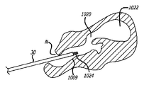
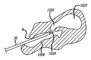
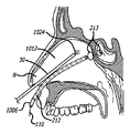
이제 도 26a 및 도 26b를 참조하면, 코 및 부비 해부학적 구조물 내에서 선회 프리즘 내시경을 사용하는 방법의 일 실시예가 기술된다. 예시의 용이성을 위해, 도 26a 및 도 26b는 콧구멍(N), 비강(1009), 및 자연 부비동 개구(1020)를 갖는 비특이적인 부비동(1022)을 도시한다. 다양한 실시예에서, 내시경(10)은 상악골, 전두골, 접형골 및/또는 사골 부비동 및 이들의 관련 개구를 다루는 시술에서 사용될 수 있다. 도 27a 내지 도 27d는, 예를 들어, 접형동의 자연 개구의 확장을 수반하는 방법을 도시한다. 그러나, 상악골 및/또는 전두골 부비동과 관련된 시술에서 본 출원의 선회 프리즘 내시경을 사용하는 것이 훨씬 더 유리할 수 있는데, 이는 이들 부비동 내로의 자연 개방부가 하나 이상의 자연적인 해부학적 구조물을 제거하지 않고서 내시경을 사용하여 시각화하기가 보통 어렵기 때문이다. 따라서, 도 26a 및 도 26b가 일반적인 부비동을 도시하고, 도 27a 내지 도 27d가 접형동을 도시하지만, 본 발명의 내시경은 임의의 부비동 및/또는 비강과 관련된 임의의 적합한 시술에서 사용될 수 있다. 추가의 대안적인 실시예에서, 본 출원의 내시경은 귀, 코, 또는 목구멍 해부학적 구조물의 다른 부분과 관련된 시술, 예를 들어 이로 한정되지 않는 유스타키오관 시술, 예를 들어 확장 및/또는 스텐트(stent) 배치, 두개-안면 골절의 수복, 기도 시술, 예를 들어 성문하 협착 확장, 편도절제술, 아데노이드절제술 등에서 사용될 수 있다.Referring now to FIGS. 26A and 26B, one embodiment of a method of using a turning prism endoscope in a nasal and sinus anatomical structure is described. For ease of illustration, FIGS. 26A and 26B show
도 26a에 도시된 바와 같이, 일 실시예에서, 선회 프리즘 내시경(10)은 광선 라인(1024)에 의해 나타내어진 바와 같이, 내시경의 관찰 각도가 대략 0도(즉, 직전방(straight ahead) 관찰)로 조절된 상태로 사람 또는 동물 대상의 콧구멍(N) 내로 삽입될 수 있다. 대안적인 실시예에서, 내시경(10)은 0도에서 관찰가능하지 않을 수 있지만, 가장 "직전방" 각도로서 약 5도 내지 약 10도에서 관찰가능할 수 있다. 어느 경우든, 의사는 직전방 관찰을 사용하여 비강(1009)을 통해 내시경(10)을 전진시켜, 예를 들어 상악동, 전두동, 접형동 또는 사골동의 개구와 같은 부비동 개구(1020)를 향해 이동할 수 있다. 도 26b는 더 전진된 위치에서의 내시경(10)을 도시한다. 내시경(10)을 전진시키는 동안 또는 그 후의 어떤 시점에서, 의사는, 예를 들어 개구(1020)의 방향으로 보기 위해, 스코프(30)의 선회 프리즘을 그의 관찰 각도를 변화시키도록 조절할 수 있다. 일 실시예에서, 내시경(10)은 자동 초점 요소를 포함하여, 선회 프리즘이 조절되고 관찰 각도가 변화될 때, 내시경(10)이 자동으로 다시 초점을 맞추도록 한다. 개구(1020)를 관찰한 후에, 의사는 관찰 각도를 동일하게 두도록 또는 다른 해부학적 구조물, 부비 해부학적 구조물 내로 삽입된 추가의 장치 등을 관찰하기 위해 추가로 조절하도록 결정할 수 있다. 일부 실시예에서, 시술 동안의 임의의 시점에서, 의사는 내시경(10)의 관찰 각도를 원하는 각도로 고정가능할 수 있다. 사람 또는 동물 대상의 콧구멍으로부터 장치를 인출할 때, 의사는 또한 선회 프리즘 관찰 각도를 0도로 다시 조절할 수 있거나 각도를 시술의 임의의 부분 동안에 있던 대로 둘 수 있다. 그러한 방법 또는 그의 다수의 변경들 중 임의의 하나는 의사가 다수의 상이한 내시경들을 절환하거나 코너 근방을 보기 위해 조직을 제거할 필요가 없이 시술 동안에 비강(1009), 부비동 개구(1020) 및/또는 부비동(1022)의 해부학적 구조물뿐만 아니라 하나 이상의 수술 장치를 관찰하게 한다.As shown in FIG. 26A, in one embodiment, the turning
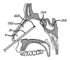
도 27a 내지 도 27d는 이러한 예에서 접형동인 부비동의 개구를 관찰하고 처치하기 위한 방법의 다양한 단계를 도시하는, 사람 두부를 통한 부분 시상 단면도의 도시이다. 도 27a에서, 선회 프리즘 내시경(10)은 콧구멍(N)을 통해 그리고 비강(1012)을 통해 접형동(1016)의 개구(1014)에 가까운 위치로 도입된다. 내시경은 제1 직전방 관찰 각도 (또는 내시경 종축으로부터 약 5도 내지 약 10도와 같은 대략적인 직전방)를 사용하여 주위의 해부학적 구조물을 관찰하도록 사용된다.27A-27D are illustrations of partial sagittal cross sections through the human head, showing various steps of the method for observing and treating openings in the sinus that are sphenoid sinuses in this example. In FIG. 27A, the turning
도 27b에서, 내시경(10)의 관찰 각도는 부비동(1016)의 개구(1014)를 관찰하기 위해 변경된다. 대안적인 실시예에서, 내시경(10)의 관찰 각도가 조절되기 전에 하나 이상의 치료 또는 진단 장치가 비강(1012) 내로 전진될 수 있다. 사실, 내시경(10)은 필요한 대로 임의의 적합한 순서 또는 방식으로 임의의 추가의 장치(들)와 함께 일반적으로 전진, 조절, 제거 등이 될 수 있다.In FIG. 27B, the viewing angle of the
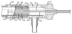
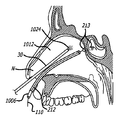
도 27c에 도시된 바와 같이, 일 실시예에서, 안내 카테터(212)가 다음으로 비강(1012) 내로 전진될 수 있지만, 일부 경우에, 안내 와이어(110) 및/또는 풍선 카테터가 반드시 미리 장착되는 것은 아닐 수 있다. 안내 와이어(110)는 이어서 부비동 개구(1014)를 통해 접형동(1016) 내로 통과하도록 안내 카테터(212)의 원위 단부로부터 전진될 수 있다. 풍선 카테터와 같은 작동 장치(1006)가 팽창가능 풍선과 같은 확대가능 부재(213)를 부비동 개구(1014) 내로 위치시키기 위해, 안내 카테터를 통해 안내 와이어(110) 위에서 도입될 수 있다.As shown in FIG. 27C, in one embodiment, the guiding
이후에, 도 27d에 도시된 바와 같이, 작동 장치(1006)는 진단 또는 치료 시술을 수행하도록 사용된다. 이러한 특정 예에서, 시술은 접형동 개구(1014)의 확장인데, 여기서 장치(1006)의 풍선은 개구(1014)를 넓히도록 확장된다. 시술의 완료 후에, 부비동 안내 카테터(212), 안내 와이어(110) 및 작동 장치(1006)는 인출되어 제거된다. 전체 시술은 선회 프리즘 내시경(10)을 사용하여 관찰될 수 있다.Thereafter, as shown in FIG. 27D, the
본 발명의 특징부들은 또한 임의의 부비동 개구, 또는 코, 부비동, 비인두(nasopharynx) 또는 인접 영역 내의 다른 인공 또는 자연 발생 해부학적 개방부 또는 통로를 확장 또는 수정하기 위해 사용될 수 있다. 이러한 또는 본 특허 출원에서 기술된 시술들 중 임의의 시술에서, 조작자는 다른 유형의 카테터를 추가로 전진시킬 수 있고, 안내 와이어(110), 안내 카테터(212) 또는 둘 모두는 조향가능(예컨대, 토크 부여가능, 능동 변형가능)하거나 성형가능하거나 유연성일 수 있다. 추가로, 다양한 대안적인 실시예에서, 내시경(10) 및 안내 카테터(212)와 같은 하나 이상의 다른 장치가 통합될 수 있다. 일 실시예에서, 예를 들어 안내 카테터(212)는 내시경(10)이 통과할 수 있는 내시경 루멘을 포함할 수 있다.Features of the present invention can also be used to expand or modify any sinus opening, or other artificial or naturally occurring anatomical openings or passages in the nose, sinuses, nasopharynx or adjacent areas. In any of these or any of the procedures described in this patent application, the operator may further advance another type of catheter, and the
스코프(30)는 부비동 안내체의 배치 동안의 형광투시경 시각화 및/또는 작동 장치(1006)에 의해 수행되는 시술의 시각화에 대한 필요성을 감소 또는 제거하는 데 유용할 수 있다. 165도의 관찰 영역을 제공하는 선회 프리즘과 함께 구성될 때, 이는 부비동 내로의 개방부 및 가능하게는 심지어 부비동 자체 내부도 보는 능력을 제공할 수 있고, 따라서 내시경은 안내 와이어(110)를 원하는 부비동 내로 안내하는 데 있어서 사용하기 위한 충분한 시각적 피드백을 제공할 수 있다.
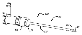
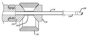
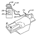
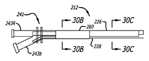
도 28은 본 발명의 선회 프리즘 내시경(10)에 사용될 수 있는 부비동 안내 시스템(210)의 일 실시예를 도시한다. 부비동 안내체(212)는 직선이거나 유연성일 수 있거나, 또는 이는 위에서 그리고 예를 들어 각각이 본 명세서에 전체적으로 참고로 포함된 미국 특허 출원 공개 제2006/004323호; 제2006/0063973호; 및 제2006/0095066호에 추가로 기술된 바와 같이 하나 이상의 미리 성형된 만곡부 또는 굽힘부를 포함할 수 있다. 부비동 안내체(212)가 만곡되거나 구부러진 실시예에서, 만곡부 또는 굽힘부의 편향 각도는 최대 약 135도의 범위 내일 수 있다. 이러한 부비동 안내 시스템(210)은 부비동 안내체(212) 및 카메라/전달체/내시경 조립체(214)를 포함한다. 부비동 안내체(212)의 이러한 실시예는 도 30a 내지 도 30c에 더 상세하게 도시되어 있다. 도시된 바와 같이, 이러한 부비동 안내체(212)는 대체로 나란한 배열의 부비동 안내체 본체(226) 및 내시경 채널(228)을 포함한다. 앞서 기술된 바와 같이, 선회 프리즘 내시경(10)은 부비동 안내 시스템(210)으로부터 분리되어 삽입될 수 있다. 그러나, 소정의 응용에서, 내시경(10)은 또한 내시경 채널(228)을 통해 삽입될 수 있다. 따라서, 시스템(210)은 또한 내시경 채널(228)이 없을 수 있다. 어느 접근에서도, 선회 프리즘 내시경은 카메라/전달체 조립체에 그리고 모니터(236) 및 비디오 레코더(240)를 포함하는 콘솔(234)에 연결될 수 있다.FIG. 28 illustrates one embodiment of a
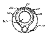
부비동 안내체 본체(226)는 생체적합성 중합체 재료로 제조된 중합체 튜브와 같은, 루멘(245)을 갖는 튜브(244)(예를 들어, 도 30b 참조)를 구현할 수 있다. 선택적으로, 라이너(246)(도 30b)가 튜브(244)의 루멘(245) 내에 배치될 수 있다. 그러한 라이너는 폴리테트라플루오로에틸렌(PTFE)과 같은 윤활성이거나 매끄러운 재료로 형성될 수 있다. 또한, 선택적으로, 튜브(244)의 근위부는 스테인레스강 하이포튜브와 같은 재료로 형성된 외측 튜브 부재(242)에 의해 둘러싸일 수 있다. 도시된 실시예에서, 튜브(244)의 원위부는 외측 튜브(242)의 원위 단부를 지나 그 외부로 연장된다. 튜브(244)의 이러한 돌출 원위부는 직선이거나 만곡형일 수 있다. 또한, 이는 제조시에 미리 성형되거나 사용시에 원하는 형상으로 순응가능할 수 있다. 부비동의 개구에 접근하는 데 사용하도록 의도될 때, 튜브(244)의 원위부는 약 0도 내지 약 120도의 각도(A)를 형성하도록 만곡될 수 있다. 예를 들어, 0, 30, 70, 90, 및 110도의 각도(A)를 갖는 일련의 부비동 안내체(212)들이 제공됨으로써, 의사가 접근될 특정 부비동 개구에 대해 가장 적절한 부비동 안내체 각도(A)를 선택하게 할 수 있다.The
추가로, 일부 실시예에서, 회전 파지부(260)가 도 28, 도 30a, 및 도 30b에서 보이는 바와 같이 부비동 안내체(210)의 근위부 둘레에 위치될 수 있다. 이러한 회전 파지부(260)는 조작자의 손의 손가락들 사이에 파지되어 쉽게 회전될 수 있는 매끄럽거나 텍스처형성된(textured) 둥근 외측 표면을 가질 수 있음(예를 들어, 이는 원통형 튜브일 수 있음)으로써, 부비동 안내체(212)가 사용될 때 부비동 안내체 회전(예를 들어, 롤링)을 용이하게 할 수 있다. 부비동 안내체(212)의 그러한 회전은 원하는 위치에서의 부비동 안내체(212)의 원위 단부의 위치설정을 포함하지만 이로 한정되지 않는 다수의 이유때문에 바람직할 수 있다.In addition, in some embodiments, the
내시경 채널을 갖는 부비동 안내 시스템을 구성하는 것이 바람직한 경우에, 채널(228)이 가요성 내시경의 전진을 안내할 수 있는 임의의 구조물(예를 들어, 튜브, 트랙, 홈, 레일 등)을 포함할 수 있는 것이 고려된다. 이들 도면에 도시된 특정 예에서, 내시경 채널(228)은 루멘(229)이 관통 연장되는 튜브(예를 들어, 중합체 튜브)를 포함한다. 도 28 내지 도 30c에서 보이는 실시예에서, 내시경 채널(228)은 부비동 안내체 본체(226)에 부착되고 실질적으로 부비동 안내체 본체의 전체 길이를 따라 연장된다. 다른 실시예에서, 내시경 채널(228)은 부비동 안내체 본체(226) 내부에 있을 수 있다. 다른 실시예에서, 내시경 채널(228)은 단속되거나 불연속적일 수 있거나, 부비동 안내체 본체(226)의 전체 길이 미만에 걸쳐 연장될 수 있다. 외측 스킨(240)이 부비동 안내체 본체(226) 및 내시경 채널(228) 둘레에서 열 수축되거나 달리 배치되어 내시경 채널(228)을 부비동 안내체 본체(226)의 외측 표면 상의 원하는 위치에 유지할 수 있다. 대안적으로, 내시경 채널(228)은 접착제, 납땜, 용접, 열 융합, 공압출, 밴딩(banding), 클리핑(clipping) 등을 포함하지만 이로 한정되지 않는, 임의의 다른 적합한 부착 물질, 장치 또는 기술에 의해 하나 이상의 위치에서 부비동 안내체 본체(226)에 부착될 수 있다. 내시경 채널(228)의 특정 원주방향 위치는 일부 응용에서, 특히 부비동 안내체 본체(226)가 그의 원위부(244)에 형성된 만곡부를 포함할 때 중요할 수 있다. 이 점에 있어서, 일부 응용에 대해, 내시경 채널(228)은 내시경 채널(228)을 통해 삽입된 내시경(10)이 인접한 해부학적 구조물로부터의 방해 없이 원하는 또는 최적의 유리한 지점으로부터의 관찰을 제공하게 하도록 부비동 안내체 본체(226) 상의 특정 원주방향 위치에 부착될 수 있다. 전술된 선회 프리즘 내시경과는 다르며 선회 프리즘을 포함하거나 가요성 구조물을 달리 형성하는 제2 내시경(도시되지 않음)이 내시경 채널을 통해 삽입될 수 있음이 또한 인식될 것이다.In cases where it is desirable to construct a sinus guidance system having an endoscope channel, the
도 28 내지 도 30c를 다시 참조하면, 근위 Y 커넥터(241)가 부비동 안내체(212)의 근위 단부에 부착될 수 있다. 이러한 Y 커넥터의 제1 아암(243b)은 부비동 안내체 본체(226)의 루멘(245)에 연결되는 암형 루어 피팅(female Luer fitting)을 포함한다. 다른 아암(243a)은 내시경 채널(226)의 루멘(229)에 연결되는 암형 루어 피팅이다.Referring back to FIGS. 28-30C, a
카메라/케이블/내시경 조립체(214)가 아암(243a)에 부착가능하다. 도 28 및 도 31에 도시된 특정 실시예에서, 카메라/케이블/내시경 조립체(214)는 조절가능한 스코프/로크 연장부(216), 카메라(220), 및 모니터 케이블(224)을 포함한다. 스코프 본체(30)는 스코프/로크 연장부(216)를 통해 그리고 내시경 채널(228)의 루멘(229)을 통해 전진될 수 있다. 도 29에 도시된 바와 같이, 광 케이블(250) 및 모니터 케이블(224)은 모니터(236), 광원(238) 및 비디오 레코더(240)를 내장하는 콘솔(234)에 연결될 수 있다. 대안적으로, 내시경(10)은 부비동 안내 시스템(212)으로부터 분리된 콘솔(234)에 직접 연결될 수 있다.Camera / cable /
본 발명은 본 발명의 소정의 예 또는 실시예를 참조하여 위에서 설명되었지만, 다양한 추가, 삭제, 변경 및 수정이 이들 예 및 실시예에 대해 이루어질 수 있고/있거나 본 발명의 의도된 사상 및 범주로부터 벗어남이 없이 등가물이 대체될 수 있다. 예를 들어, 하나의 실시예 또는 예의 임의의 요소 또는 속성이, 다른 실시예 또는 예를 그의 의도된 용도에 대해 부적합하게 만들지 않는다면, 그 실시예 또는 예에 통합되거나 함께 사용될 수 있다. 게다가, 특정 상황, 재료, 물질의 조성, 공정, 공정 단계 또는 단계들을 본 발명의 목적, 사상 및 범주에 대해 적응시키도록 많은 수정이 이루어질 수 있다. 모든 그러한 수정은 본 명세서에 첨부된 특허청구범위의 범주 내에 있도록 의도된다.While the invention has been described above with reference to certain examples or embodiments of the invention, various additions, deletions, changes and modifications may be made to these examples and embodiments and / or depart from the spirit and scope of the invention. Equivalents can be substituted without this. For example, any element or attribute of one embodiment or example may be incorporated in or used with that embodiment or example unless it makes the other embodiment or example unsuitable for its intended use. In addition, many modifications may be made to adapt a particular situation, material, composition of matter, process, process step, or steps, to the objects, spirit, and scope of the present invention. All such modifications are intended to be within the scope of the claims appended hereto.
Claims (42)
가변 관찰 방향 내시경을, 상기 내시경이 상기 내시경의 종축에 대해 약 0도 내지 약 15도의 제1 관찰 방향으로 조절된 상태로, 비강(nasal cavity) 내로 도입하는 단계;
상기 치료 장치를 상기 비강 내로 도입하는 단계;
상기 내시경을 상기 부비동 개방부 또는 통로를 향하는 제2 관찰 방향으로 조절하는 단계;
상기 치료 장치를 상기 부비동 개방부 내로 또는 상기 부비동 개방부를 통해 전진시키는 단계; 및
상기 제2 관찰 방향으로 조절된 상기 내시경을 사용하여 상기 부비동 개방부 또는 통로, 또는 상기 치료 장치 중 적어도 하나를 관찰하는 단계를 포함하는 방법.A method for advancing a treatment device into, or through, an opening or passage into a paranasal sinus,
Introducing a variable viewing direction endoscope into a nasal cavity with the endoscope adjusted in a first viewing direction of about 0 degrees to about 15 degrees relative to the longitudinal axis of the endoscope;
Introducing the treatment device into the nasal cavity;
Adjusting the endoscope in a second viewing direction towards the sinus opening or passage;
Advancing the treatment device into or through the sinus opening; And
Observing at least one of the sinus opening or passageway or the treatment device using the endoscope adjusted to the second viewing direction.
가변 관찰 방향 내시경을, 상기 내시경이 상기 내시경의 종축에 대해 약 0도 내지 약 15도의 제1 관찰 방향으로 조절된 상태로, 비강 내로 도입하는 단계;
카테터의 원위 팁(distal tip)을 부비동 개방부 또는 통로 내에 또는 상기 부비동 개방부 또는 통로 부근에 위치시키도록 안내 카테터를 상기 비강 내로 도입하는 단계;
상기 내시경을 상기 부비동 개방부 또는 통로를 향하는 제2 관찰 방향으로 조절하는 단계;
상기 가요성 장치를 상기 안내 카테터의 루멘을 통해 그리고 상기 부비동 개방부 내로 또는 상기 부비동 개방부를 통해 전진시키는 단계; 및
상기 제2 관찰 방향으로 조절된 상기 내시경을 사용하여 상기 부비동 개방부 또는 통로, 또는 상기 가요성 장치 중 적어도 하나를 관찰하는 단계를 포함하는 방법.A method for advancing a flexible device into an opening or passageway into a sinus,
Introducing a variable viewing direction endoscope into the nasal cavity with the endoscope adjusted in a first viewing direction of about 0 degrees to about 15 degrees relative to the longitudinal axis of the endoscope;
Introducing a guide catheter into the nasal cavity to locate a distal tip of the catheter in or near the sinus opening or passage;
Adjusting the endoscope in a second viewing direction towards the sinus opening or passage;
Advancing the flexible device through the lumen of the intraocular catheter and into or through the sinus opening; And
Observing at least one of the sinus opening or passageway, or the flexible device using the endoscope adjusted in the second viewing direction.
풍선 카테터를 상기 안내 와이어 위에서 전진시켜 상기 풍선 카테터의 풍선을 상기 부비동 개구 내에 적어도 부분적으로 위치시키는 단계; 및
상기 풍선을 확대시켜 상기 부비동 개구를 확장시키는 단계를 추가로 포함하는 방법.The method of claim 18,
Advancing a balloon catheter over the guide wire to position the balloon of the balloon catheter at least partially within the sinus opening; And
Expanding the balloon to expand the sinus opening.
상기 방법은;
상기 부비동 내에 배치된 상기 조명 와이어의 원위 단부로부터 광을 투과시키는 단계; 및
상기 투과된 광을 상기 부비동의 외부로부터 관찰하는 단계를 추가로 포함하는 방법.The method of claim 14, wherein advancing the flexible device includes advancing an illumination wire through the opening into the sinus,
The method;
Transmitting light from the distal end of the illumination wire disposed within the sinus; And
Observing said transmitted light from outside of said sinus.
가변 관찰 각도 내시경을, 상기 내시경이 제1 관찰 각도로 조절된 상태로, 상기 대상의 두부 내로 도입하는 단계;
상기 제1 관찰 각도를 갖는 상기 내시경을 사용하여 상기 두부 내의 해부학적 구조물을 관찰하는 단계;
상기 내시경의 종축을 중심으로 상기 내시경의 손잡이의 제1 부분을 회전시켜 상기 내시경을 제2 관찰 각도로 조절하는 단계로서, 상기 손잡이의 제1 부분이 상기 내시경의 샤프트에 대해 회전하는, 상기 내시경을 상기 제2 관찰 각도로 조절하는 단계; 및
상기 제2 관찰 각도를 갖는 상기 내시경을 사용하여 상기 두부 내의 해부학적 구조물을 관찰하는 단계를 포함하는 방법.A method for observing anatomical structures in the head of a human or animal subject,
Introducing a variable viewing angle endoscope into the head of the subject, with the endoscope adjusted to the first viewing angle;
Observing anatomical structures in the head using the endoscope having the first viewing angle;
Rotating the first portion of the handle of the endoscope about the longitudinal axis of the endoscope to adjust the endoscope to a second viewing angle, wherein the first portion of the handle rotates relative to the shaft of the endoscope. Adjusting to the second viewing angle; And
Observing anatomical structures in the head using the endoscope having the second viewing angle.
근위 단부(proximal end), 원위 단부, 및 대략 5 ㎜ 이하의 외경을 갖는 긴 샤프트;
상기 샤프트의 원위 단부에서 또는 상기 원위 단부 부근에서 상기 샤프트를 따라 배치된 관찰 창(viewing window);
상기 내시경의 관찰 방향을 변화시키기 위해 상기 원위 단부 부근에서 상기 샤프트 내에 배치된 피벗가능한 프리즘; 및
프리즘이 피벗할 때 상기 관찰 창을 통해 획득되는 시야를 자동으로 초점을 맞추도록 구성된, 샤프트 내에 배치된 자동 초점 렌즈를 포함하는 가변 관찰 방향 내시경.A variable viewing orientation endoscope configured to pass into the head of a human or animal subject,
An elongated shaft having a proximal end, a distal end, and an outer diameter of about 5 mm or less;
A viewing window disposed along the shaft at or near the distal end of the shaft;
A pivotable prism disposed in the shaft near the distal end to change the viewing direction of the endoscope; And
A variable viewing direction endoscope comprising an autofocus lens disposed within the shaft, configured to automatically focus the field of view obtained through the viewing window when the prism is pivoted.
근위 단부, 원위 단부, 및 대략 5 ㎜ 이하의 외경을 갖는 긴 샤프트;
상기 샤프트의 원위 단부에서 또는 상기 원위 단부 부근에서 상기 샤프트를 따라 배치된 관찰 창;
상기 내시경의 관찰 방향을 변화시키기 위해 상기 원위 단부 부근에서 상기 샤프트 내에 배치된 피벗가능한 프리즘; 및
상기 긴 샤프트의 상기 근위 단부와 결합된 손잡이로서, 상기 손잡이가 상기 프리즘을 피벗시킴으로써 상기 내시경의 관찰 각도를 조절하기 위한 제1 회전식 다이얼을 포함하고, 상기 제1 회전식 다이얼이 상기 샤프트의 종축을 중심으로 회전하는, 상기 손잡이를 포함하는 가변 관찰 방향 내시경.A variable viewing orientation endoscope configured to pass into the head of a human or animal subject,
An elongated shaft having a proximal end, a distal end, and an outer diameter of about 5 mm or less;
An observation window disposed along the shaft at or near the distal end of the shaft;
A pivotable prism disposed in the shaft near the distal end to change the viewing direction of the endoscope; And
A handle associated with the proximal end of the elongated shaft, the handle including a first rotary dial for adjusting the viewing angle of the endoscope by pivoting the prism, the first rotary dial centering the longitudinal axis of the shaft Rotating with a variable observation direction endoscope comprising the handle.
Applications Claiming Priority (4)
| Application Number | Priority Date | Filing Date | Title |
|---|---|---|---|
| US8494908P | 2008-07-30 | 2008-07-30 | |
| US61/084,949 | 2008-07-30 | ||
| US12/502,101 | 2009-07-13 | ||
| US12/502,101 US20100030031A1 (en) | 2008-07-30 | 2009-07-13 | Swing prism endoscope |
Publications (1)
| Publication Number | Publication Date |
|---|---|
| KR20110049819A true KR20110049819A (en) | 2011-05-12 |
Family
ID=41609056
Family Applications (1)
| Application Number | Title | Priority Date | Filing Date |
|---|---|---|---|
| KR1020117004165A KR20110049819A (en) | 2008-07-30 | 2009-07-16 | Swing prism endoscope |
Country Status (11)
| Country | Link |
|---|---|
| US (1) | US20100030031A1 (en) |
| EP (1) | EP2328462A1 (en) |
| JP (1) | JP5567013B2 (en) |
| KR (1) | KR20110049819A (en) |
| CN (1) | CN102112041B (en) |
| AU (1) | AU2009276931A1 (en) |
| BR (1) | BRPI0916721A2 (en) |
| CA (1) | CA2732735A1 (en) |
| MX (1) | MX2011001098A (en) |
| RU (1) | RU2538626C2 (en) |
| WO (1) | WO2010014421A1 (en) |
Families Citing this family (189)
| Publication number | Priority date | Publication date | Assignee | Title |
|---|---|---|---|---|
| US8317816B2 (en) | 2002-09-30 | 2012-11-27 | Acclarent, Inc. | Balloon catheters and methods for treating paranasal sinuses |
| US20070167682A1 (en) | 2004-04-21 | 2007-07-19 | Acclarent, Inc. | Endoscopic methods and devices for transnasal procedures |
| US7803150B2 (en) | 2004-04-21 | 2010-09-28 | Acclarent, Inc. | Devices, systems and methods useable for treating sinusitis |
| US20190314620A1 (en) | 2004-04-21 | 2019-10-17 | Acclarent, Inc. | Apparatus and methods for dilating and modifying ostia of paranasal sinuses and other intranasal or paranasal structures |
| US7462175B2 (en) | 2004-04-21 | 2008-12-09 | Acclarent, Inc. | Devices, systems and methods for treating disorders of the ear, nose and throat |
| US9101384B2 (en) | 2004-04-21 | 2015-08-11 | Acclarent, Inc. | Devices, systems and methods for diagnosing and treating sinusitis and other disorders of the ears, Nose and/or throat |
| US9399121B2 (en) | 2004-04-21 | 2016-07-26 | Acclarent, Inc. | Systems and methods for transnasal dilation of passageways in the ear, nose or throat |
| US8894614B2 (en) | 2004-04-21 | 2014-11-25 | Acclarent, Inc. | Devices, systems and methods useable for treating frontal sinusitis |
| US20060063973A1 (en) | 2004-04-21 | 2006-03-23 | Acclarent, Inc. | Methods and apparatus for treating disorders of the ear, nose and throat |
| US20060004323A1 (en) | 2004-04-21 | 2006-01-05 | Exploramed Nc1, Inc. | Apparatus and methods for dilating and modifying ostia of paranasal sinuses and other intranasal or paranasal structures |
| US7654997B2 (en) | 2004-04-21 | 2010-02-02 | Acclarent, Inc. | Devices, systems and methods for diagnosing and treating sinusitus and other disorders of the ears, nose and/or throat |
| US10188413B1 (en) | 2004-04-21 | 2019-01-29 | Acclarent, Inc. | Deflectable guide catheters and related methods |
| US8702626B1 (en) | 2004-04-21 | 2014-04-22 | Acclarent, Inc. | Guidewires for performing image guided procedures |
| US7559925B2 (en) | 2006-09-15 | 2009-07-14 | Acclarent Inc. | Methods and devices for facilitating visualization in a surgical environment |
| US7419497B2 (en) | 2004-04-21 | 2008-09-02 | Acclarent, Inc. | Methods for treating ethmoid disease |
| US7361168B2 (en) | 2004-04-21 | 2008-04-22 | Acclarent, Inc. | Implantable device and methods for delivering drugs and other substances to treat sinusitis and other disorders |
| US9554691B2 (en) | 2004-04-21 | 2017-01-31 | Acclarent, Inc. | Endoscopic methods and devices for transnasal procedures |
| US8747389B2 (en) | 2004-04-21 | 2014-06-10 | Acclarent, Inc. | Systems for treating disorders of the ear, nose and throat |
| US8764729B2 (en) | 2004-04-21 | 2014-07-01 | Acclarent, Inc. | Frontal sinus spacer |
| US8932276B1 (en) | 2004-04-21 | 2015-01-13 | Acclarent, Inc. | Shapeable guide catheters and related methods |
| US8951225B2 (en) | 2005-06-10 | 2015-02-10 | Acclarent, Inc. | Catheters with non-removable guide members useable for treatment of sinusitis |
| US8114113B2 (en) | 2005-09-23 | 2012-02-14 | Acclarent, Inc. | Multi-conduit balloon catheter |
| US8190389B2 (en) | 2006-05-17 | 2012-05-29 | Acclarent, Inc. | Adapter for attaching electromagnetic image guidance components to a medical device |
| US9820688B2 (en) | 2006-09-15 | 2017-11-21 | Acclarent, Inc. | Sinus illumination lightwire device |
| US8485199B2 (en) | 2007-05-08 | 2013-07-16 | Acclarent, Inc. | Methods and devices for protecting nasal turbinate during surgery |
| US10206821B2 (en) | 2007-12-20 | 2019-02-19 | Acclarent, Inc. | Eustachian tube dilation balloon with ventilation path |
| US8182432B2 (en) | 2008-03-10 | 2012-05-22 | Acclarent, Inc. | Corewire design and construction for medical devices |
| US8550988B2 (en) * | 2008-04-21 | 2013-10-08 | Covidien Lp | Endoscopic cleaner |
| CN102112040B (en) | 2008-07-30 | 2015-04-01 | 阿克拉伦特公司 | Paranasal ostium finder devices and methods |
| US20130006055A1 (en) | 2008-07-30 | 2013-01-03 | Acclarent, Inc. | Swing prism endoscope |
| US20130184532A1 (en) * | 2011-07-25 | 2013-07-18 | Eric A. Goldfarb | Endoscopic method for viewing a sinus opening |
| US8945142B2 (en) | 2008-08-27 | 2015-02-03 | Cook Medical Technologies Llc | Delivery system for implanting nasal ventilation tube |
| CN103623498B (en) | 2008-09-18 | 2015-12-30 | 阿克拉伦特公司 | Be used for the treatment of the method and apparatus of otorhinolaryngology disease |
| US8435290B2 (en) | 2009-03-31 | 2013-05-07 | Acclarent, Inc. | System and method for treatment of non-ventilating middle ear by providing a gas pathway through the nasopharynx |
| US7978742B1 (en) | 2010-03-24 | 2011-07-12 | Corning Incorporated | Methods for operating diode lasers |
| WO2010141850A1 (en) * | 2009-06-05 | 2010-12-09 | Entrigue Surgical, Inc. | Systems and devices for providing therapy of an anatomical structure |
| WO2011008981A1 (en) * | 2009-07-15 | 2011-01-20 | Regents Of The University Of Minnesota | Implantable devices for treatment of sinusitis |
| US8435261B2 (en) | 2009-07-15 | 2013-05-07 | Regents Of The University Of Minnesota | Treatment and placement device for sinusitis applications |
| DE102009049143B3 (en) * | 2009-10-12 | 2010-12-30 | Sopro-Comeg Gmbh | Rigid, rod shaped endoscope for examining inner organ of patient, has magnet within inner space, where movement of inner hollow tubes against innermost hollow tube takes place by forces produced by magnet |
| US8986201B2 (en) | 2009-11-14 | 2015-03-24 | Spiway Llc | Surgical tissue protection sheath |
| US20120203069A1 (en) * | 2009-11-14 | 2012-08-09 | Blake Hannaford | Surgical shield for soft tissue protection |
| US9011326B2 (en) | 2009-11-14 | 2015-04-21 | Spiway Llc | Soft tissue shield for trans-orbital surgery |
| US20110118551A1 (en) * | 2009-11-14 | 2011-05-19 | SPI Surgical, Inc. | Collateral soft tissue protection surgical device |
| US9451981B2 (en) | 2009-11-14 | 2016-09-27 | Spiway Llc | Surgical tissue protection sheath |
| DE102010010948A1 (en) * | 2010-03-10 | 2011-09-15 | Karl Storz Gmbh & Co. Kg | Swing prism endoscope |
| US20110230829A1 (en) * | 2010-03-19 | 2011-09-22 | Fitzgerald Patrick J | Arterial Tamponade Device and Method |
| US20110230907A1 (en) * | 2010-03-19 | 2011-09-22 | Sinocclusive Llc | Arterial tamponade device and method |
| US9375139B2 (en) * | 2010-07-29 | 2016-06-28 | Cannuflow, Inc. | Arthroscopic system |
| DE102010040992A1 (en) * | 2010-09-17 | 2012-03-22 | Henke-Sass, Wolf Gmbh | Endoscope with variable viewing direction |
| DE102010040990A1 (en) * | 2010-09-17 | 2012-03-22 | Henke-Sass, Wolf Gmbh | Endoscope with variable viewing direction |
| US9763567B2 (en) | 2010-10-20 | 2017-09-19 | Covidien Lp | Endoscope wiper blade cleaner |
| US8690764B2 (en) | 2010-10-20 | 2014-04-08 | Covidien Lp | Endoscope cleaner |
| CN102028446A (en) * | 2010-11-10 | 2011-04-27 | 江苏富兰肯光电科技有限公司 | Electronic cranial nerve endoscope |
| DE102011005255A1 (en) * | 2011-03-08 | 2012-09-13 | Olympus Winter & Ibe Gmbh | Device for switching a viewing direction of a video endoscope |
| DE102011007190A1 (en) * | 2011-04-12 | 2012-10-18 | Henke-Sass, Wolf Gmbh | endoscope |
| DE102011007484A1 (en) * | 2011-04-15 | 2012-10-18 | Henke-Sass, Wolf Gmbh | Endoscope with variable viewing direction |
| JP2014518381A (en) * | 2011-06-15 | 2014-07-28 | コーニンクレッカ フィリップス エヌ ヴェ | Optical angular momentum induced hyperpolarization in interventional applications |
| DE102011078969B4 (en) * | 2011-07-11 | 2019-02-21 | Olympus Winter & Ibe Gmbh | Non-contact magnetic coupling for an endoscope and endoscope |
| US8998985B2 (en) | 2011-07-25 | 2015-04-07 | Rainbow Medical Ltd. | Sinus stent |
| JP5399587B2 (en) * | 2011-08-10 | 2014-01-29 | オリンパスメディカルシステムズ株式会社 | Medical equipment |
| US9757150B2 (en) * | 2011-10-18 | 2017-09-12 | Treble Innovations | Portable endoscope and method of use thereof |
| US10029079B2 (en) | 2011-10-18 | 2018-07-24 | Treble Innovations | Endoscopic peripheral |
| EP2667235A4 (en) * | 2011-10-28 | 2015-04-29 | Olympus Medical Systems Corp | Endoscope illumination optical system |
| US20130158525A1 (en) * | 2011-12-09 | 2013-06-20 | Adn International, Llc | Flexible channel surgical instruments |
| US9146576B2 (en) * | 2012-02-06 | 2015-09-29 | Arthrex, Inc. | Arthroscope rotation mechanisms and methods of endoscopic rotation |
| US10143358B2 (en) | 2012-02-07 | 2018-12-04 | Treble Innovations, Llc | System and method for a magnetic endoscope |
| DE102012202552B3 (en) * | 2012-02-20 | 2013-07-11 | Olympus Winter & Ibe Gmbh | Video endoscope with adjustable viewing direction |
| US20140012075A1 (en) * | 2012-07-09 | 2014-01-09 | Gyrus Acmi, Inc., D.B.A. Olympus Surgical Technologies America | Sinus endoscope |
| US9763563B2 (en) * | 2012-07-11 | 2017-09-19 | Karl Storz Imaging, Inc. | Endoscopic camera single-button mode activation |
| WO2014039945A1 (en) | 2012-09-10 | 2014-03-13 | Acclarent, Inc. | Inflator for dilation of anatomical passageway |
| US9962531B2 (en) | 2012-09-10 | 2018-05-08 | Acclarent, Inc. | Inflator for dilation of anatomical passageway |
| DE102012220578A1 (en) | 2012-11-12 | 2014-05-15 | Olympus Winter & Ibe Gmbh | Endoscope with swiveling optics |
| DE102012111290A1 (en) * | 2012-11-22 | 2014-05-22 | Karl Storz Gmbh & Co. Kg | An endoscope with adjustable viewing direction |
| JP5981039B2 (en) * | 2013-01-29 | 2016-08-31 | オリンパス株式会社 | Endoscope |
| US10986984B2 (en) | 2013-03-13 | 2021-04-27 | Spiway Llc | Surgical tissue protection sheath |
| US11039735B2 (en) | 2013-03-13 | 2021-06-22 | Spiway Llc | Surgical tissue protection sheath |
| US20140275775A1 (en) | 2013-03-14 | 2014-09-18 | Acclarent, Inc. | Narrowband Illumination of Paranasal Cavities for Visual Localization of Target Tissue |
| US9198559B2 (en) | 2013-03-14 | 2015-12-01 | Acclarent, Inc. | Device and method to display the angle of view endoscopically when using a multi-angle endoscope |
| US9408756B2 (en) | 2013-03-15 | 2016-08-09 | Acclarent, Inc. | Nasal fluid management device |
| US9433437B2 (en) | 2013-03-15 | 2016-09-06 | Acclarent, Inc. | Apparatus and method for treatment of ethmoid sinusitis |
| US9623213B2 (en) | 2013-03-15 | 2017-04-18 | Acclarent, Inc. | Uncinate process support for ethmoid infundibulum illumination |
| US9408955B2 (en) | 2013-03-15 | 2016-08-09 | Acclarent, Inc. | Nasal fluid management device |
| US9629684B2 (en) | 2013-03-15 | 2017-04-25 | Acclarent, Inc. | Apparatus and method for treatment of ethmoid sinusitis |
| US9604041B2 (en) | 2013-03-15 | 2017-03-28 | Acclarent, Inc. | Nasal fluid management device |
| US9615959B2 (en) | 2013-03-15 | 2017-04-11 | Acclarent, Inc. | Uncinate process support for ethmoid infundibulum illumination |
| US9323049B2 (en) * | 2013-05-07 | 2016-04-26 | Novartis Ag | Forward scanning optical probes with one or more rotating components |
| JP2015016177A (en) * | 2013-07-12 | 2015-01-29 | Hoyaサービス株式会社 | Medical instrument |
| US20150031946A1 (en) * | 2013-07-24 | 2015-01-29 | Nidus Medical, Llc | Direct vision cryosurgical probe and methods of use |
| US9182285B2 (en) * | 2013-08-15 | 2015-11-10 | Siemens Energy, Inc. | Methods regarding optical probe having an inner tube with separable tube sections to house optical elements |
| US9195044B2 (en) * | 2013-08-15 | 2015-11-24 | Siemens Energy, Inc | Optical probe having an inner tube with separable tube sections to house optical elements |
| US9662000B2 (en) | 2013-08-28 | 2017-05-30 | Hankookin, Inc. | Visualization apparatus and system for enhanced hand-eye coordination |
| EP3048999A1 (en) | 2013-09-27 | 2016-08-03 | Acclarent, Inc. | Enhanced gripping features for nasal and paranasal sinus systems |
| US9433763B2 (en) | 2013-09-27 | 2016-09-06 | Acclarent, Inc. | Sinus wall implant |
| WO2015064521A1 (en) * | 2013-10-30 | 2015-05-07 | オリンパスメディカルシステムズ株式会社 | Image capture device |
| US10016580B2 (en) | 2013-12-17 | 2018-07-10 | Biovision Technologies, Llc | Methods for treating sinus diseases |
| US9516995B2 (en) | 2013-12-17 | 2016-12-13 | Biovision Technologies, Llc | Surgical device for performing a sphenopalatine ganglion block procedure |
| US9694163B2 (en) | 2013-12-17 | 2017-07-04 | Biovision Technologies, Llc | Surgical device for performing a sphenopalatine ganglion block procedure |
| US9510743B2 (en) | 2013-12-17 | 2016-12-06 | Biovision Technologies, Llc | Stabilized surgical device for performing a sphenopalatine ganglion block procedure |
| US10178950B2 (en) * | 2013-12-20 | 2019-01-15 | Novartis Ag | Imaging probes and associated devices, systems, and methods utilizing an elastomeric optical element |
| US9956384B2 (en) | 2014-01-24 | 2018-05-01 | Cook Medical Technologies Llc | Articulating balloon catheter and method for using the same |
| DE102014202612B4 (en) * | 2014-02-13 | 2017-08-17 | Olympus Winter & Ibe Gmbh | Prism holder assembly and endoscope with variable viewing direction |
| DE102014208559A1 (en) | 2014-05-07 | 2015-11-12 | Olympus Winter & Ibe Gmbh | Endoscope with swiveling optics |
| US10772489B2 (en) | 2014-07-09 | 2020-09-15 | Acclarent, Inc. | Guidewire navigation for sinuplasty |
| US10463242B2 (en) | 2014-07-09 | 2019-11-05 | Acclarent, Inc. | Guidewire navigation for sinuplasty |
| US10569060B2 (en) | 2014-07-09 | 2020-02-25 | Acclarent, Inc. | Guide catheters with guidewire deflection features |
| US9999437B2 (en) | 2014-08-27 | 2018-06-19 | Acclarent, Inc. | Method and apparatus for forming opening in a sinus wall |
| US10130799B2 (en) | 2014-08-27 | 2018-11-20 | Acclarent, Inc. | Inflator with varying mechanical advantage |
| JP5932165B1 (en) * | 2014-09-02 | 2016-06-08 | オリンパス株式会社 | Endoscope |
| WO2016040820A1 (en) | 2014-09-12 | 2016-03-17 | Acclarent, Inc. | Uncinate process support for ethmoid infundibulum illumination |
| US10238845B2 (en) | 2014-09-19 | 2019-03-26 | Acclarent, Inc. | Balloon catheter assembly |
| USD772406S1 (en) | 2014-12-16 | 2016-11-22 | Biovision Technologies, Llc | Surgical device |
| IL236418A (en) | 2014-12-23 | 2016-07-31 | Visionsense Ltd | Rotatable oblique viewing stereoendoscope |
| US9723977B2 (en) * | 2015-02-26 | 2017-08-08 | Olympus Corporation | Insertion method |
| US9955852B2 (en) | 2015-03-30 | 2018-05-01 | Acclarent, Inc. | Guide catheter with image capture and light emission features |
| US10244935B2 (en) | 2015-03-30 | 2019-04-02 | Acclarent, Inc. | Handle with features to secure a catheter assembly to an endoscope |
| US10335319B2 (en) | 2015-03-30 | 2019-07-02 | Acclarent, Inc. | Method and apparatus for cleaning isthmus of eustachian tube |
| US10493251B2 (en) | 2015-03-30 | 2019-12-03 | Acclarent, Inc. | Handle with features to couple catheter assembly with endoscope and actuate catheter |
| US9931026B2 (en) | 2015-03-30 | 2018-04-03 | Acclarent, Inc. | Balloon catheter with image capture and light emission features |
| US10064555B2 (en) | 2015-03-31 | 2018-09-04 | Acclarent, Inc. | Illuminating guidewire with optical sensing |
| US10602966B2 (en) | 2015-03-31 | 2020-03-31 | Acclarent, Inc. | System and method for detecting characteristics of eustachian tube |
| US9757018B2 (en) | 2015-03-31 | 2017-09-12 | Acclarent, Inc. | Medical guidewire with integral light transmission |
| JP6043041B1 (en) * | 2015-04-09 | 2016-12-14 | オリンパス株式会社 | Endoscope objective optical system |
| US10137285B2 (en) | 2015-04-22 | 2018-11-27 | Acclarent, Inc. | Balloon dilation system with malleable internal guide |
| US9872973B2 (en) | 2015-06-30 | 2018-01-23 | Acclarent, Inc. | Luer members for coaxial lumen catheter |
| US10016581B2 (en) | 2015-06-30 | 2018-07-10 | Acclarent, Inc. | Balloon catheter with tactile feedback features and reinforced lumen |
| US9913570B2 (en) | 2015-08-07 | 2018-03-13 | Enlightenvue Llc | Endoscope with variable profile tip |
| US10123685B2 (en) * | 2015-08-25 | 2018-11-13 | Acclarent, Inc. | Apparatus and method to illuminate and orient guidewire |
| US10512763B2 (en) | 2015-08-25 | 2019-12-24 | Acclarent, Inc. | Dilation catheter with expandable stop element |
| US10517608B2 (en) | 2015-08-27 | 2019-12-31 | Acclarent, Inc. | Apparatus to form opening in ethmoid bulla and irrigate ethmoid sinus cavity |
| US9999433B2 (en) | 2015-08-27 | 2018-06-19 | Acclarent, Inc. | Apparatus and method to secure turbinate to nasal septum |
| US10070993B2 (en) | 2015-10-30 | 2018-09-11 | Acclarent, Inc. | System and method for treatment of eustachian tube from middle ear approach |
| US10779891B2 (en) | 2015-10-30 | 2020-09-22 | Acclarent, Inc. | System and method for navigation of surgical instruments |
| US10118012B2 (en) | 2015-10-30 | 2018-11-06 | Acclarent, Inc. | System and method for anesthetizing eustachian tube |
| US10034681B2 (en) | 2015-10-30 | 2018-07-31 | Acclarent, Inc. | Fluid communication features for Eustachian tube dilation instrument |
| US10137286B2 (en) | 2015-10-30 | 2018-11-27 | Acclarent, Inc. | Apparatus for bending malleable guide of surgical instrument |
| US10085889B2 (en) | 2015-10-30 | 2018-10-02 | Acclarent, Inc. | System and method for treatment of eustachian tube from oral approach |
| US10894149B2 (en) | 2016-03-08 | 2021-01-19 | Acclarent, Inc. | Dilation catheter assembly with adjustment features |
| US10625062B2 (en) | 2016-03-08 | 2020-04-21 | Acclarent, Inc. | Dilation catheter assembly with rapid change components |
| CN105877686A (en) * | 2016-06-08 | 2016-08-24 | 焦作天元精密光学实验室(普通合伙) | Angle-continuously-variable endoscope |
| KR101724315B1 (en) * | 2016-08-11 | 2017-04-10 | 한국과학기술연구원 | Steerable Laser Operation device |
| US20180085174A1 (en) | 2016-09-23 | 2018-03-29 | Acclarent, Inc. | Suction device for use in image-guided sinus medical procedure |
| US10456519B2 (en) | 2016-10-14 | 2019-10-29 | Acclarent, Inc. | Apparatus and method for irrigating sinus cavity |
| US10485609B2 (en) | 2016-10-18 | 2019-11-26 | Acclarent, Inc. | Dilation balloon with RF energy delivery feature |
| US10639462B2 (en) | 2016-10-18 | 2020-05-05 | Acclarent, Inc. | Dilation system |
| US10512764B2 (en) | 2016-10-25 | 2019-12-24 | Acclarent, Inc. | Actuation features for dilation system |
| US10507310B2 (en) | 2016-10-27 | 2019-12-17 | Acclarent, Inc. | Dilation apparatus with malleable feature and apparatus to bend malleable feature |
| WO2018081222A1 (en) * | 2016-10-31 | 2018-05-03 | Boston Scientific Scimed, Inc. | Medical systems, devices, and related methods |
| DE102017100056A1 (en) * | 2017-01-03 | 2018-07-05 | Olympus Winter & Ibe Gmbh | Video endoscope with swiveling viewing direction and handle for a medical shaft instrument |
| US10610308B2 (en) | 2017-02-01 | 2020-04-07 | Acclarent, Inc. | Navigation guidewire with interlocked coils |
| US20180264237A1 (en) | 2017-03-20 | 2018-09-20 | Acclarent, Inc. | Navigation guidewire with shielded sensor coil |
| US20180280046A1 (en) | 2017-03-30 | 2018-10-04 | Acclarent, Inc. | Guidewire with optics tube containing core wire |
| US11376401B2 (en) | 2017-04-26 | 2022-07-05 | Acclarent, Inc. | Deflectable guide for medical instrument |
| US10561370B2 (en) | 2017-04-26 | 2020-02-18 | Accalrent, Inc. | Apparatus to secure field generating device to chair |
| US11812985B2 (en) | 2017-06-30 | 2023-11-14 | Enlightenvue, Inc. | Endoscopy systems and methods of use thereof |
| US11027105B2 (en) | 2017-07-13 | 2021-06-08 | Biosense Webster (Israel) Ltd. | Adjustable instrument for dilation of anatomical passageway |
| US20190060618A1 (en) | 2017-08-25 | 2019-02-28 | Acclarent, Inc. | Core wire assembly for guidewire |
| US10967159B2 (en) | 2017-08-31 | 2021-04-06 | Acclarent, Inc. | Sinuplasty guide with plurality of configurations |
| US10835327B2 (en) | 2017-09-05 | 2020-11-17 | Acclarent, Inc. | Sensor guided instrument with penetrating feature |
| US11278706B2 (en) | 2017-09-08 | 2022-03-22 | Acclarent, Inc. | Guidewire assembly with intertwined core wire |
| US10973603B2 (en) | 2017-09-08 | 2021-04-13 | Acclarent, Inc. | Dilation system with illuminating orientation indicator features |
| US10736647B2 (en) | 2017-10-30 | 2020-08-11 | Acclarent, Inc. | Dilation catheter with navigation sensor and vent passageway in tip |
| DE102017010535A1 (en) * | 2017-11-14 | 2019-05-16 | Uromed Kurt Drews Kg | Medical device for moving a medical instrument |
| US10857333B2 (en) | 2017-11-27 | 2020-12-08 | Acclarent, Inc. | Guidewire with integral expandable dilator |
| US20190159666A1 (en) | 2017-11-27 | 2019-05-30 | Acclarent, Inc. | Surgical illumination system |
| US20190160268A1 (en) | 2017-11-27 | 2019-05-30 | Acclarent, Inc. | Guide catheter for dilation system |
| US10864046B2 (en) | 2017-12-04 | 2020-12-15 | Acclarent, Inc. | Dilation instrument with navigation and distally located force sensor |
| US20190167151A1 (en) | 2017-12-05 | 2019-06-06 | Acclarent, Inc. | System and method for tracking patient movement during guided medical procedure |
| US10881377B2 (en) | 2017-12-05 | 2021-01-05 | Acclarent, Inc. | Sinus dilation catheter with ultrasonic imaging feature |
| US10974034B2 (en) | 2017-12-11 | 2021-04-13 | Acclarent, Inc. | Force measurement instrument for sinuplasty procedure |
| US20190175887A1 (en) | 2017-12-13 | 2019-06-13 | Acclarent, Inc. | Dilation instrument with proximally located force sensor |
| US20190184142A1 (en) | 2017-12-14 | 2019-06-20 | Acclarent, Inc. | Guidewire assembly with offset core wires |
| US10888382B2 (en) | 2017-12-14 | 2021-01-12 | Acclarent, Inc. | Mounted patient tracking component for surgical navigation system |
| US20190374129A1 (en) | 2018-06-07 | 2019-12-12 | Acclarent, Inc. | Endoscope with integral navigation sensor |
| US11622805B2 (en) | 2018-06-08 | 2023-04-11 | Acclarent, Inc. | Apparatus and method for performing vidian neurectomy procedure |
| US11147629B2 (en) * | 2018-06-08 | 2021-10-19 | Acclarent, Inc. | Surgical navigation system with automatically driven endoscope |
| WO2020005910A1 (en) | 2018-06-28 | 2020-01-02 | Sandler Scientific, Llc | Sino-nasal rinse delivery device with agitation, flow-control and integrated medication management system |
| RU185793U1 (en) * | 2018-07-02 | 2018-12-19 | Федеральное государственное бюджетное образовательное учреждение высшего образования "Санкт-Петербургский государственный архитектурно-строительный университет" | TELEVISION ENDOSCOPE |
| US11202014B2 (en) | 2018-07-06 | 2021-12-14 | Medos International Sari | Camera scope electronic variable angle of view |
| US11032481B2 (en) * | 2018-07-06 | 2021-06-08 | Medos International Sarl | Camera scope electronic variable prism |
| US20200054243A1 (en) | 2018-08-17 | 2020-02-20 | Acclarent, Inc. | Endoscope with anatomy elevation assembly |
| US10687698B2 (en) | 2018-09-12 | 2020-06-23 | Enlightenvue Llc | Direct endoluminal- and/or endovascular-illumination systems and methods of use thereof |
| US11412921B2 (en) | 2018-10-02 | 2022-08-16 | Covidien Lp | Multi lumen access device |
| US11583313B1 (en) | 2018-12-06 | 2023-02-21 | Spiway Llc | Surgical access sheath and methods of use |
| US11786296B2 (en) * | 2019-02-15 | 2023-10-17 | Accularent, Inc. | Instrument for endoscopic posterior nasal nerve ablation |
| US11357542B2 (en) | 2019-06-21 | 2022-06-14 | Covidien Lp | Valve assembly and retainer for surgical access assembly |
| DE102019123053A1 (en) * | 2019-08-28 | 2021-03-04 | Olympus Winter & Ibe Gmbh | Endoscope with optical filter arrangement and use |
| US11850106B2 (en) | 2020-05-06 | 2023-12-26 | Covidien Lp | Cleaning cap for a surgical access device |
| DE102020115258B3 (en) * | 2020-06-09 | 2021-09-16 | Karl Storz Se & Co. Kg | Endoscope with swiveling image capturing device |
| CN113633397A (en) * | 2021-08-17 | 2021-11-12 | 武汉帕菲鱼医疗器械有限公司 | Tissue pushing and expanding sheath plate |
Family Cites Families (21)
| Publication number | Priority date | Publication date | Assignee | Title |
|---|---|---|---|---|
| US3804081A (en) * | 1971-07-29 | 1974-04-16 | Olympus Optical Co | Endoscope |
| JPS4932484U (en) * | 1972-06-19 | 1974-03-20 | ||
| JPS4920979A (en) * | 1972-06-19 | 1974-02-23 | ||
| JPS6223443Y2 (en) * | 1980-10-27 | 1987-06-15 | ||
| DE8810044U1 (en) * | 1988-08-03 | 1988-11-17 | Effner Gmbh | Optical adjustment device |
| JPH07327916A (en) * | 1994-06-02 | 1995-12-19 | Olympus Optical Co Ltd | Visual field direction varying type endoscope |
| JP3106930B2 (en) * | 1995-09-25 | 2000-11-06 | 富士写真光機株式会社 | Ultrasound endoscope |
| JP3717559B2 (en) * | 1995-09-29 | 2005-11-16 | オリンパス株式会社 | Endoscope |
| JPH10248851A (en) * | 1997-03-12 | 1998-09-22 | Olympus Optical Co Ltd | Ultrasonic endoscope |
| EP0865760B1 (en) * | 1997-03-21 | 2005-01-12 | Stryker Corporation | Circumferential transillumination of anatomic junctions using light energy |
| GB2354836B (en) * | 1999-09-28 | 2003-06-04 | Keymed | Improvements relating to borescopes and endoscopes with variable direction of view |
| JP3345645B2 (en) * | 2000-06-20 | 2002-11-18 | 東京大学長 | Body cavity observation device |
| FR2832516B1 (en) * | 2001-11-19 | 2004-01-23 | Tokendo Sarl | ROTARY ENDOSCOPES WITH A DEVIED DISTAL VIEW |
| RU2228718C1 (en) * | 2003-02-13 | 2004-05-20 | Шкарубо Алексей Николаевич | Method for low-invasive surgical treatment of large and giant tumors of cranial foundation of endo-extracellular localization |
| JP2005257734A (en) * | 2004-03-09 | 2005-09-22 | Fujinon Corp | Electronic endoscope device provided with auto-focus function |
| US20070167682A1 (en) * | 2004-04-21 | 2007-07-19 | Acclarent, Inc. | Endoscopic methods and devices for transnasal procedures |
| US7462175B2 (en) | 2004-04-21 | 2008-12-09 | Acclarent, Inc. | Devices, systems and methods for treating disorders of the ear, nose and throat |
| US20060004323A1 (en) | 2004-04-21 | 2006-01-05 | Exploramed Nc1, Inc. | Apparatus and methods for dilating and modifying ostia of paranasal sinuses and other intranasal or paranasal structures |
| US7803150B2 (en) * | 2004-04-21 | 2010-09-28 | Acclarent, Inc. | Devices, systems and methods useable for treating sinusitis |
| US20060063973A1 (en) * | 2004-04-21 | 2006-03-23 | Acclarent, Inc. | Methods and apparatus for treating disorders of the ear, nose and throat |
| JP5022580B2 (en) * | 2005-08-09 | 2012-09-12 | Hoya株式会社 | Endoscope device |
-
2009
- 2009-07-13 US US12/502,101 patent/US20100030031A1/en not_active Abandoned
- 2009-07-16 RU RU2011107230/14A patent/RU2538626C2/en not_active IP Right Cessation
- 2009-07-16 AU AU2009276931A patent/AU2009276931A1/en not_active Abandoned
- 2009-07-16 EP EP09790517A patent/EP2328462A1/en not_active Withdrawn
- 2009-07-16 MX MX2011001098A patent/MX2011001098A/en active IP Right Grant
- 2009-07-16 KR KR1020117004165A patent/KR20110049819A/en active IP Right Grant
- 2009-07-16 CA CA2732735A patent/CA2732735A1/en not_active Abandoned
- 2009-07-16 JP JP2011521178A patent/JP5567013B2/en not_active Expired - Fee Related
- 2009-07-16 WO PCT/US2009/050800 patent/WO2010014421A1/en active Application Filing
- 2009-07-16 CN CN200980130769.2A patent/CN102112041B/en not_active Expired - Fee Related
- 2009-07-16 BR BRPI0916721A patent/BRPI0916721A2/en not_active IP Right Cessation
Also Published As
| Publication number | Publication date |
|---|---|
| EP2328462A1 (en) | 2011-06-08 |
| CA2732735A1 (en) | 2010-02-04 |
| MX2011001098A (en) | 2011-03-15 |
| BRPI0916721A2 (en) | 2016-07-26 |
| AU2009276931A1 (en) | 2010-02-04 |
| US20100030031A1 (en) | 2010-02-04 |
| CN102112041B (en) | 2015-06-03 |
| JP5567013B2 (en) | 2014-08-06 |
| JP2011529724A (en) | 2011-12-15 |
| CN102112041A (en) | 2011-06-29 |
| WO2010014421A1 (en) | 2010-02-04 |
| RU2011107230A (en) | 2012-09-10 |
| RU2538626C2 (en) | 2015-01-10 |
Similar Documents
| Publication | Publication Date | Title |
|---|---|---|
| JP5567013B2 (en) | Revolving prism type endoscope | |
| US9808144B2 (en) | Swing prism endoscope | |
| JP2011529724A5 (en) | ||
| US10926059B2 (en) | Method of making a sealed lumen and associated computing module | |
| US10856727B2 (en) | Endoscopic methods and devices for transnasal procedures | |
| US10448811B2 (en) | Medical device introduction and imaging system, and associated method | |
| EP2306886B1 (en) | Paranasal ostium finder devices | |
| US9107574B2 (en) | Endoscopic methods and devices for transnasal procedures | |
| US20080058595A1 (en) | Medical device introduction systems and methods | |
| KR20180120101A (en) | Deflectable guide for medical instrument | |
| EP3189798B1 (en) | Endoscopic treatment instrument, treatment instrument unit, and treatment system | |
| JP2015534855A (en) | Sinus access system | |
| EP3476271A2 (en) | Dilation catheter with navigation sensor and vent passageway in tip | |
| US20110245602A1 (en) | Flexible endoscope with full-length lumen | |
| WO2017087579A1 (en) | Medical device introduction and imaging system, and associated method | |
| US20160106300A1 (en) | Flexible Endoscopic Exoskeleton Surgical System | |
| WO2021154657A1 (en) | Fully integrated, disposable tissue visualization device with off axis viewing |
Legal Events
| Date | Code | Title | Description |
|---|---|---|---|
| A201 | Request for examination | ||
| E902 | Notification of reason for refusal | ||
| E701 | Decision to grant or registration of patent right |