KR20110011368U - Woodworking Angle Gold Sweeper - Google Patents
Woodworking Angle Gold Sweeper Download PDFInfo
- Publication number
- KR20110011368U KR20110011368U KR2020100005752U KR20100005752U KR20110011368U KR 20110011368 U KR20110011368 U KR 20110011368U KR 2020100005752 U KR2020100005752 U KR 2020100005752U KR 20100005752 U KR20100005752 U KR 20100005752U KR 20110011368 U KR20110011368 U KR 20110011368U
- Authority
- KR
- South Korea
- Prior art keywords
- bar
- body bar
- angle
- push
- right wing
- Prior art date
- Legal status (The legal status is an assumption and is not a legal conclusion. Google has not performed a legal analysis and makes no representation as to the accuracy of the status listed.)
- Granted
Links
Images
Classifications
-
- B—PERFORMING OPERATIONS; TRANSPORTING
- B25—HAND TOOLS; PORTABLE POWER-DRIVEN TOOLS; MANIPULATORS
- B25H—WORKSHOP EQUIPMENT, e.g. FOR MARKING-OUT WORK; STORAGE MEANS FOR WORKSHOPS
- B25H7/00—Marking-out or setting-out work
Landscapes
- Engineering & Computer Science (AREA)
- Mechanical Engineering (AREA)
- Sawing (AREA)
Abstract
본 고안은 인테리어 목공 작업시 몸체바 선단에서 좌우 회전하는 날개바에 의해 코너, 모서리 등의 각도 측정 및 금긋기, 절단 작업을 간편하게 행하는 목공용 각도 금긋기자에 관한 것으로서, 좀더 상세하게는 상부 길이방향을 따라 눈금부를 형성하는 몸체바(10)와, 상기 몸체바 선단에 좌우로 대향 회전하도록 힌지 결합되는 좌우 날개바(20)(20')와, 상기 좌우 날개바와 연결대(25)(25') 양단으로 힌지 연결되어 좌우 날개바(20)(20')의 좌우 회전에 따라 몸체바의 길이 방향을 따라 전후 이동하여 눈금부에 의해 각도 측정하는 슬라이드 결합구(30)로 구성하되; 상기 몸체바(10) 저면에 탄발 출몰하도록 설치되는 푸시바(50)는 전방에 몸체바의 전방으로 연장되는 연장부(51)를 형성하고, 상기 푸시바(50)의 상하로 설치되는 제1스프링(60)과, 전후 길이방향으로 설치되는 제2스프링(70)에 의해 몸체바의 상하 및 전후로 탄발 이동하면서 출몰 사용하도록 제공하므로서, 인테리어 목공 작업시 몸체바 선단에서 좌우 회전하는 날개바에 의해 코너, 모서리 등의 각도 측정 및 금긋기, 절단 작업을 간편하게 행하되, 특히 몰딩 절단 작업시에 몸체바 하부에서 탄발 출몰하는 푸시바가 몸체바의 전방으로 출몰하도록 구조 등을 개량하여 전동 톱 절단기의 베이스가 소형인 경우에 종래 설치 어려움의 문제를 해결하여 그 작업성, 효율성을 더욱 극대화하는 효과를 갖는 것이다.The present invention relates to an angle carved angler for woodworking, which makes it easy to measure angles, corners, corners, etc. of the corners, corners, etc. by wing bars that rotate left and right at the tip of the body bar during interior woodworking. Body bar 10 to form a scale along the left and right wing bar (20, 20 ') hinged to be rotated opposite to the left and right to the front end of the body bar, and both ends of the left and right wing bar and connecting rod (25, 25') The hinge is connected to the left and right wing bar (20, 20 ') according to the left and right rotation of the body bar to move forward and backward along the longitudinal direction of the slide coupling sphere 30 to measure the angle by the graduation portion; The push bar 50 installed on the bottom surface of the body bar 10 has an extension portion 51 extending in front of the body bar in the front, and is installed up and down of the push bar 50. The spring 60 and the second spring 70 installed in the longitudinal direction of the front and rear of the body bar are provided to be used while being moved while moving up and down, and the corner bar by the wing bar rotated left and right at the body bar tip during interior woodwork work. In addition, the angle of corners, chamfering, and cutting can be easily performed.In particular, the base of the chain saw cutter is small by improving the structure such that the push bar that spouts from the lower part of the body bar emerges in front of the body bar during molding cutting operation. In the case of solving the problem of the conventional installation difficulty is to have the effect of further maximizing its workability, efficiency.
Description
본 고안은 인테리어 목공 작업시 몸체바 선단에서 좌우 회전하는 날개바에 의해 코너, 모서리 등의 각도 측정 및 금긋기, 절단 작업을 간편하게 행하는 목공용 각도 금긋기자에 관한 것으로서, 좀더 상세하게는 몰딩 절단 작업시에 몸체바나 날개바 하부에서 탄발 출몰하는 푸시바에 의해 전동 톱절단기의 베이스에 고정 설치하여 절단 위치를 설정하되, 상기 몸체바의 푸시바 구조 등을 개량하여 전동 톱 절단기의 베이스가 소형인 경우에 종래 설치 어려움의 문제를 해결하여 작업성, 효율성을 더욱 극대화하는 목공용 각도 금긋기자의 개량에 관한 것이다.The present invention relates to an angle chamfer for woodworking that makes it easy to measure angles, corners, corners, etc., and to draw and cut corners by wing bars that rotate left and right at the tip of the body bar during interior woodworking. In the case where the base of the power saw cutter is small by improving the push bar structure of the body bar by setting the cutting position by fixedly installing the base of the electric saw cutter by the push bar which is projected from the lower part of the body bar or the wing bar. To solve the problem of installation difficulties, and to improve the workmanship, the efficiency of the woodworking angle chamfer further.
일반적으로 건축 현장, 특히 인테리어 목공 작업을 행하는 현장에서 주로 행하는 작업은 몰딩의 코너, 모서리 각도 측정 및 측정된 각도로 금긋기 작업 및 몰딩 절단 작업 등이다.In general, the main work in the construction site, especially in the interior woodworking work is the corner of the molding, the measurement of the angle of the corners and the cutting of the molding to the measured angle and the molding operation.
이와 같은 작업중에서 몰딩의 코너, 모서리 각도 측정 및 금긋기 작업은 종래 각각 별도의 각도자, 금긋기자를 구비하여 사용하므로 작업이 매우 불편함은 물론 작업 오차 등이 자주 발생되는 문제점이 있었다.In this work, the corner, corner angle measurement, and gold flicking of the molding are conventionally provided with separate anglers and gold fuzzers, so that the work is very inconvenient and there is a problem in that work errors are frequently generated.
이러한 종래 문제점을 해결하고자 본 출원인은 특허출원 제10-792685호에 목공용 각도 금긋기자를 선 출원한 바 있다.In order to solve such a conventional problem, the applicant has filed an angle gold cutter for woodworking in Patent Application No. 10-792685.
이는 상부 길이방향을 따라 눈금부를 형성하는 몸체바와, 상기 몸체바 선단에 좌우로 대향 회전하도록 힌지 결합되는 좌우 날개바와, 상기 좌우 날개바와 연결대 양단으로 힌지 연결되어 좌우 날개바의 좌우 회전에 따라 몸체바의 길이 방향을 따라 전후 이동하여 눈금부에 의해 각도 측정하는 슬라이드 결합구로 구성되어 상기 좌우 날개바를 대향 회전시켜 코너, 모서리 각도 측정 및 금긋기 작업을 간편하고 일정하게 행함은 물론 절단작업도 효율적으로 행하도록 제공하는 것이다.It is a body bar forming a scale along the upper longitudinal direction, the left and right wing bar hinged to rotate opposite to the left and right to the front end of the body bar, the hinge is connected to both ends of the left and right wing bar and the connecting bar body bar according to the left and right rotation of the left and right wing bar It is composed of a slide coupler for measuring the angle by the graduation by moving back and forth along the longitudinal direction of the left and right wing bar to rotate the corners, corner angle measurement and gold drawing work easily and consistently, as well as efficiently cutting To provide.
특히, 몰딩 절단 작업의 경우에 상기 각도 금긋기자의 몸체바나 좌우 날개바 저면에 탄발 출몰하는 푸시바를 전동 톱 절단기의 베이스 중앙으로 형성되는 톱 안내홈에 삽입 설치하여 일정하게 위치 설정하므로 몰딩을 간편하면서 효과적으로 절단하게 되는 것이다.Particularly, in the case of molding cutting operation, the push bar is inserted into the saw guide groove formed at the center of the base of the electric saw cutter in a constant position by inserting and pushing the push bar on the bottom of the body bar or the left and right wing bars of the angle drawer. It will cut effectively.
그러나 상기 본 출원인에 의해 선 출원된 각도 금긋기자는 몸체바 저면의 푸시바가 몸체바 중앙 부위에 탄발 설치되기 때문에 전동 톱 절단기의 베이스가 소형인 경우에 상기 푸시바를 베이스의 톱 안내홈에 삽입 설치함이 곤란하게 되므로 절단 위치의 설정 작업이 어려워 작업성이 저하되는 문제점이 있었다.However, the angle drawer previously filed by the present applicant is inserted into the top guide groove of the base when the base of the chain saw cutter is small because the push bar of the bottom of the body bar is installed in the center of the body bar. Since this becomes difficult, setting work of the cutting position is difficult, and there is a problem that workability is lowered.
즉, 상기 푸시바가 몸체바 저면의 전방 끝단에 위치하면, 전동 톱 절단기의 베이스가 소형인 경우에도 톱 안내홈으로 효과적 설치가 가능하게 되나, 이는 상기 몸체바의 구조상, 그리고 상기 좌우 날개부에 간섭으로 인해 곤란함이 있었다.That is, when the push bar is located at the front end of the bottom of the body bar, even if the base of the electric saw cutter is small, it can be effectively installed as a saw guide groove, which interferes with the structure of the body bar and the left and right wings Due to the difficulty.
이에 본 출원인은 선 출원된 각도 금긋기자의 코너, 모서리의 각도 측정, 금긋기 작업, 절단 작업의 우수한 잇점을 유지하면서 전동 톱 절단기에서의 소형 베이스의 절단 작업을 고려하여 작업성, 효율성을 개선하기 위해 연구 노력하였다.In this regard, the present applicant can improve the workability and efficiency by considering the cutting of the small base in the chainsaw cutter while maintaining the excellent advantages of the corner, corner angle measurement, the gold cutting operation, and the cutting operation of the pre-applied angle gold cutter. Research effort.
본 고안은 상기한 종래 기술 및 본 출원인에 의해 선 출원된 기술이 갖는 제반 문제점을 해결하고자 고안된 것으로서, 인테리어 목공 작업시 몸체바 선단에서 좌우 회전하는 날개바에 의해 코너, 모서리 등의 각도 측정 및 금긋기, 절단 작업을 간편하게 행하되, 특히 몰딩 절단 작업시에 몸체바 하부에서 탄발 출몰하는 푸시바가 몸체바의 전방으로 출몰하도록 구조 등을 개량하여 전동 톱절단기의 베이스가 소형인 경우에 종래 설치 어려움의 문제를 해결하고, 또한 몸체바의 눈금부를 개량하여 그 작업성, 효율성을 더욱 극대화하는데 그 목적이 있다.The present invention is designed to solve the problems of the prior art and the technology previously filed by the applicant, the angle measurement of corners, corners, etc. by the wing bar to rotate left and right at the body bar tip during interior woodwork work , But the cutting operation is simple, but in the case of molding cutting operation, the push bar, which is projected from the lower part of the body bar to improve the structure, etc. to the front of the body bar to improve the problem of the conventional installation difficulties when the base of the electric saw cutter is small It is also aimed at maximizing the workability and efficiency by improving the scale of the body bar.
이러한 본 고안은, 상부 길이방향을 따라 눈금부를 형성하는 몸체바와, 상기 몸체바 선단에 좌우로 대향 회전하도록 힌지 결합되는 좌우 날개바와, 상기 좌우 날개바와 연결대 양단으로 힌지 연결되어 좌우 날개바의 좌우 회전에 따라 몸체바의 길이 방향을 따라 전후 이동하여 눈금부에 의해 각도 측정하는 슬라이드 결합구로 구성하되; 상기 몸체바와 좌우 날개바 저면 중앙에 탄발 출몰하도록 설치되는 푸시바에 의해 전동 톱절단기의 베이스 중앙으로 형성되는 톱 안내홈에 삽입하여 설치 사용하는 것에 있어; 상기 몸체바의 푸시바는 전방에 몸체바의 전방으로 연장되는 연장부를 형성하고, 상기 푸시바의 상하로 설치되는 제1스프링과, 전후 길이방향으로 설치되는 제2스프링에 의해 몸체바의 상하 및 전후로 탄발 이동하면서 몸체바 저면 조립홈에서 출몰 사용하도록 함에 그 특징이 있다.The present invention, the body bar forming a scale along the upper longitudinal direction, the left and right wing bar hinged to rotate opposite to the left and right to the front end of the body bar, hinged to both ends of the left and right wing bar and the connecting rod is rotated left and right wing bar To move forward and backward along the longitudinal direction of the body bar according to the slide coupling to measure the angle by the scale; In the installation and use to insert into the saw guide groove formed in the center of the base of the electric saw cutter by a push bar installed in the center of the body bar and the left and right wing bar bottom; The push bar of the body bar is formed in the front extending to the front of the body bar extending, the top and bottom of the body bar by the first spring installed in the vertical direction of the push bar, and the second spring installed in the longitudinal direction While moving forward and backward, the body bar is characterized in that it is used to stand out from the bottom assembly groove.
본 고안 상기 푸시바의 전방에는 좌우 날개바의 내측 절첩 이동시 좌우 날개바에 맞닿아 푸시바를 전후로 탄발 이동하도록 좌우 로울러를 설치 구성함에 그 특징이 있다.The front of the push bar is characterized in that the left and right rollers are installed to be in contact with the left and right wing bar when moving the inner side of the left and right wing bar to move the push bar forward and backward.
본 고안 상기 제2스프링은 상기 푸시바의 양측 길이방향으로 설치되는 안내봉에 스프링을 각각 삽입하여 상기 푸시바를 관통하여 설치되는 걸림핀 양단이 스프링 전방에서 안내봉에 삽입 설치되어 푸시바를 전후로 탄발 이동하도록 구성함에 그 특징이 있다.The second spring of the present invention is inserted into the guide rods installed in both longitudinal directions of the push bar, respectively, so that both ends of the locking pins installed through the push bar are inserted into the guide rods from the front of the spring to move the push bar back and forth. It is characterized by the configuration.
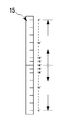
본 고안 본 고안 몸체부의 눈금부는 좌우 날개부가 일직선 위치의 중앙 기준점(180°위치)에서 상부나 하부로 대향 회전 이동함에 의해 중앙의 180°에서 0°로 대향되게 각도의 증감을 이루도록 형성함에 그 특징이 있다.The graduated portion of the body portion is formed so that the left and right wing parts are made to increase or decrease the angle to face the 180 ° to 0 ° from the center by the opposite rotation to the upper or lower from the center reference point (180 ° position) of the straight position There is this.
이러한 본 고안은 인테리어 목공 작업시 몸체바 선단에서 좌우 회전하는 날개바에 의해 코너, 모서리 등의 각도 측정 및 금긋기, 절단 작업을 간편하게 행하되, 특히 몰딩 절단 작업시에 몸체바 하부에서 탄발 출몰하는 푸시바가 몸체바의 전방으로 출몰하도록 구조 등을 개량하여 전동 톱절단기의 베이스가 소형인 경우에 종래 설치 어려움의 문제를 해결하고, 몸체바의 눈금부를 개량하여 그 작업성, 효율성을 더욱 극대화하는 효과를 갖는 것이다.The present invention is easy to measure the corners, corners, corners, corners, corners, corners, etc. by the wing bar rotates left and right at the end of the body bar during interior carpentry work, but in particular, the push bar that emerges from the lower part of the body bar during molding cutting work By improving the structure and so on in front of the body bar, when the base of the chain saw cutter is small, it solves the problem of the conventional installation difficulties, and improves the scale of the body bar to have the effect of maximizing its workability and efficiency. will be.
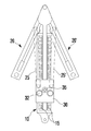
도 1은 본 고안의 평면 구성도.
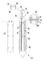
도 2는 본 고안의 저면 구성도.
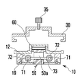
도 3 및 도 4는 본 고안의 단면 구성도.
도 5는 본 고안의 전동 톱 절단기에 설치 사용상태를 보여주는 평면도.
도 6은 본 고안의 눈금부를 보여주는 평면도.
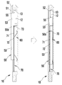
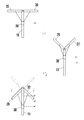
도 7은 본 고안의 날개바를 이용한 대칭 각도 설정 예를 보여주는 순서도.1 is a plan view of the present invention.
Figure 2 is a bottom configuration of the present invention.
3 and 4 is a cross-sectional configuration of the present invention.
5 is a plan view showing a state of use installed in the electric saw cutter of the present invention.
6 is a plan view showing a scale of the present invention.
7 is a flow chart showing an example of setting the angle of symmetry using the wing bar of the present invention.
이하, 상기한 본 고안의 바람직한 실시 예를 첨부도면을 참조하여 구체적으로 살펴보기로 한다.Hereinafter, preferred embodiments of the present invention will be described in detail with reference to the accompanying drawings.
즉, 본 고안 목공용 각도 금긋기자는 도 1 내지 도 7에 도시된 바와 같이 상부 길이방향을 따라 눈금부를 형성하는 몸체바(10)와, 상기 몸체바 선단에 좌우로 대향 회전하도록 힌지 결합되는 좌우 날개바(20)(20')와, 상기 좌우 날개바와 연결대(25)(25') 양단으로 힌지 연결되어 좌우 날개바(20)(20')의 좌우 회전에 따라 몸체바의 길이 방향을 따라 전후 이동하여 눈금부에 의해 각도 측정하는 슬라이드 결합구(30)로 구성하되,That is, the present invention woodworking angle drawer as shown in Figures 1 to 7
상기 몸체바(10)와 좌우 날개바(20)(20') 저면 중앙에 탄발 출몰하도록 설치되는 푸시바에 의해 전동 톱 절단기(100)의 베이스(110) 중앙으로 형성되는 톱 안내홈(112)에 삽입하여 설치 사용하는 것에 있어서,In the top guide groove 112 formed in the center of the base 110 of the electric saw cutter 100 by a push bar installed in the center of the bottom of the
상기 몸체바(10)의 푸시바(50)는 전방에 몸체바의 전방으로 연장되는 연장부(51)를 형성하고,The
상기 푸시바(50)의 상하로 설치되는 제1스프링(60)과, 전후 길이방향으로 설치되는 제2스프링(70)에 의해 몸체바의 상하 및 전후로 탄발 이동하면서 몸체바 저면 조립홈(12)에서 출몰 사용하도록 이루어진다.Body bar
이때, 상기 푸시바(50)의 전방에는 좌우 날개바(20)(20')의 내측 절첩 이동시 좌우 날개바에 맞닿아 푸시바를 전후로 탄발 이동하도록 좌우 로울러(55)(55)가 설치 구성된다.At this time, in front of the
그리고 상기 푸시바(50)의 전방 선단에 경사 지지부(52)와 상기 푸시바가 삽입되는 조립홈(12) 전방에 상기 경사 지지부에 대응되는 경사를 갖는 경사 지지면(13)을 형성하여 상호 지지 설치하도록 구성된다.In addition, the
또한, 상기 제1스프링(60)은 도면에서와 같이 판스프링이나 그 밖에 탄발스프링을 적용하여 구성된다.In addition, the
그리고 상기 제2스프링(70)은 푸시바(50)의 양측 길이방향으로 설치되는 안내봉(71)에 스프링(72)을 각각 삽입하여 상기 푸시바를 관통하여 설치되는 걸림핀(73) 양단이 스프링(72) 전방에서 안내봉에 삽입 설치되어 푸시바를 전후로 탄발 이동하도록 구성된다.The
이때 상기 걸림핀(73)이 삽입되는 푸시바(50)의 삽입공(50a)은 상하 장공으로 형성하여 푸시바의 출몰 작동이 가능하도록 구성된다.At this time, the
또한, 상기 안내봉(71)은 몸체바에 삽입하거나 별도 고정 브라켓에 의해 고정 설치할 수 있음은 물론이다.In addition, the
그리고 상기 푸시바(50)의 저면에는 푸시바를 전후로 탄발 이동시 파지하도록 파지홈(53)을 적어도 하나 이상 형성하여 구성된다.And at the bottom of the
또한, 본 고안 몸체부(10)의 눈금부(15)는 좌우 날개부(20)(20')가 일직선 위치의 중앙 기준점(180°위치)에서 상부나 하부로 대향 회전 이동함에 의해 중앙의 180°에서 0°로 대향되게 각도의 증감을 이루도록 형성하여 구성된다.In addition, the
미설명부호로서, 19는 몸체바(10) 저면에 설치되는 푸시바(50)의 제2스프링(70)을 커버하도록 조립되는 커버판, 32는 슬라이드 결합구에서 눈금부를 확대 관찰하는 확대경, 35는 슬라이드 결합구를 고정하는 고정볼트를 나타내는 것이다.As the
다음은 상기와 같이 구성되는 본 고안의 작동 및 작용에 대해 살펴보기로 한다.Next will be a look at the operation and action of the subject innovation configured as described above.
본 고안은 단일 공구로서 몸체바(10) 전방에 힌지 결합된 좌우 날개바(20)(20')를 좌우 회전 조절하면서 건축물이나 건축자재의 코너, 모서리 등의 각도를 측정한다.The present invention measures the angle of the corners, corners, etc. of the building or building materials while rotating the left and
그리고 상기 측정된 각도로 각종 목재에 금긋기 작업은 물론 전동 톱 절단기(100)에 의한 절단 작업을 효과적으로 행하게 되는 것이다.And the cutting operation by the chainsaw cutter 100 as well as the gold cutting work on various wood at the measured angle.
특히, 상기 전동 톱 절단기(100)에 의한 절단 작업시에는 좌우 날개바(20)(20)에 의해 측정된 각도 또는 그 1/2 각도로 몰딩을 절단하여 이음 결합하게 된다.In particular, during the cutting operation by the electric saw cutter 100, the molding is cut at the angle measured by the left and
이때 상기 몸체바(10)나 좌우 날개바(20)(20) 저면의 푸쉬바를 전동 톱 절단기(100)의 베이스(110) 중앙으로 형성된 톱 안내홈(112)에 삽입한 상태로 베이스를 회전 조절하여 절단 위치를 맞추게 되는 것이다.At this time, the base bar is rotated in the state in which the push bar of the bottom of the
더우기 본 고안은 상기 베이스(100)의 크기가 작은 경우에도 상기 몸체바(10) 저면의 푸시바(50)가 전방으로 연장부(51)를 연장 형성하고 있기 때문에 종래와 같이 삽입 곤란함 없이 삽입 고정하여 정확한 절단 가공을 제공하게 되는 것이다.Furthermore, even if the size of the base 100 is small, since the
즉, 상기 몸체바(10) 저면의 푸시바(50)가 전방으로 연장 형성되어 전동 톱 절단기(100)의 베이스(110) 중앙으로 형성되는 톱 안내홈(112)에 효과적으로 삽입하여 절단 작업을 행할 수 있게 되는 것이다.That is, the
또한, 상기 몸체바(10) 저면의 푸시바(50)는 전방으로 연장 형성되기 때문에 좌우 날개바(20)(20')의 회전 조절시에 간섭될 수 있는데, 이때 상기 좌우 날개바(20)(20')에 푸시바 전방의 좌우 로울러(55)(55)가 날개바에 안내되어 푸시바를 전후로 탄발 이동하면서 사용 가능하게 되는 것이다.In addition, since the
또한, 상기 몸체바(10) 저면의 푸시바(50)를 사용하지 않는 경우에는 푸시바(50)를 제2스프링(70)에 의해 후방으로 탄발 이동한다.In addition, when the
이때, 상기 제2스프링(70)은 푸시바(50)의 양측 길이방향으로 설치되는 안내봉(71)에 삽입된 스프링(72)을 걸림핀(73)의 양단이 지지하여 탄발 압축하면서 후방으로 탄발 이동하는 것이다.At this time, the
그리고 후방으로 탄발 이동된 푸시바(50)는 다시 제1스프링(60)에 의해 내측으로 탄발 가압하여 상기 푸시바 선단의 경사 지지부(52)가 조립홈(12) 전방의 경사 지지면(13)에 탄발 삽입하면서 지지되게 조립홈(12)에 삽입 결합하는 것이다.In addition, the
이와 같은 상태에서 상기 푸시바(50)를 다시 돌출 사용하고자 하는 경우에는 상기 푸시바를 후방으로 탄발 이동함에 의해 상기 푸시바의 경사 지지부(52)가 경사 지지면(13)에서 이탈하면서 제1스프링(60)에 의해 외측으로 탄발 돌출됨과 함께 제2스프링(70)에 의해 전방으로 탄발 이동되게 연장하여 사용하게 되는 것이다.In this case, when the
한편, 본 고안은 건축물이나 건축자재의 코너, 모서리 등의 각도를 예각 또는 둔각으로 측정한 후, 이에 대칭되는 둔각 또는 예각으로 금긋기 작업은 물론 절단 작업을 간편하게 행할 수 있는 것이다.On the other hand, the present invention is to measure the angle of the corners, corners, etc. of the building or building material at an acute or obtuse angle, and then can easily perform a cutting operation as well as a cutting operation at an obtuse or acute angle symmetrical thereto.
즉, 상기 몸체바(10)의 좌우 날개부(20)(20')를 180°(중앙 기준점)에서 상부로 회전시켜 예각의 모서리 각도를 측정하면 상기 몸체바(10)의 슬라이드 결합구(30)가 상승하면서 눈금부(15)의 각도, 예를 들면 90°각도를 측정한다.That is, when the left and
이 상태에서 상기 측정된 각도 90°만큼 예각이 아닌 둔각을 이루도록 하여금긋기나 절단 작업을 행하는 경우에 상기 좌우 날개부(20(20')를 상부가 아닌 하부로 회전시키되, 상기 180°(중앙 기준점)에서 하부로 90°만큼 눈금부(15)를 확인하며 간편하고 정확하게 이동 조절하여 작업할 수 있는 것이다.In this state, the left and right wing portions 20 (20 ′) are rotated to the lower side rather than the upper side when the drawing or cutting operation is performed so that the measured angle is 90 degrees, not an acute angle, but is 180 degrees (center reference point). Check the
10: 몸체바 20,20': 날개바
25,25': 연결대 30: 결합구
50: 푸시바 51: 연장부
60: 제1스프링 70: 제2스프링
12: 조립홈 55: 로울러
52: 경사 지지부 13: 경사 지지면
71: 안내봉 72: 스프링
73: 걸림핀 50a: 삽입공
53: 파지홈 15: 눈금부10:
25,25 ': Connecting rod 30: Coupler
50: push bar 51: extension part
60: first spring 70: second spring
12: assembly groove 55: roller
52: inclined support portion 13: inclined support surface
71: guide rod 72: spring
73: locking
53: grip groove 15: graduations
Claims (4)
상기 몸체바(10)의 푸시바(50)는 전방에 몸체바의 전방으로 연장되는 연장부(51)를 형성하고,
상기 푸시바(50)의 상하로 설치되는 제1스프링(60)과, 전후 길이방향으로 설치되는 제2스프링(70)에 의해 몸체바의 상하 및 전후로 탄발 이동하면서 몸체바 저면 조립홈(12)에서 출몰 사용하도록 이루어진 것을 특징으로 하는 목공용 각도 금긋기자.
Body bar 10 forming a scale along the upper longitudinal direction, the left and right wing bar (20, 20 ') hinged to rotate opposite to the left and right to the front end of the body bar, and the left and right wing bar and connecting rod 25 ( 25 ') is hinged at both ends and configured as a slide coupler (30) to measure the angle by the scale by moving back and forth along the longitudinal direction of the body bar according to the left and right rotation of the left and right wing bar (20, 20'); In the top guide groove 112 formed in the center of the base 110 of the electric saw cutter 100 by a push bar installed in the center of the bottom of the body bar 10 and the left and right wing bar 20, 20 ' In the angle carpenter for woodworking to insert and use,
The push bar 50 of the body bar 10 forms an extension portion 51 extending in the front of the body bar in the front,
Body bar bottom assembling groove 12 while moving up and down and front and rear of the body bar by the first spring 60 is installed up and down of the push bar 50 and the second spring 70 installed in the longitudinal direction Angler for woodworking, characterized in that made for use in haunting.
상기 푸시바(50)의 전방에는 좌우 날개바(20)(20')의 내측 절첩 이동시 좌우 날개바에 맞닿아 푸시바를 전후로 탄발 이동하도록 좌우 로울러(55)(55)가 설치 구성되어 이루어진 것을 특징으로 하는 목공용 각도 금긋기자.
The method of claim 1,
The left and right rollers 55 and 55 are installed in front of the push bar 50 so as to be in contact with the left and right wing bars when the inner folding of the left and right wing bars 20 and 20 ′ moves. Let's cut the angle for woodworking.
상기 제2스프링(70)은 상기 푸시바(50)의 양측 길이방향으로 설치되는 안내봉(71)에 스프링(72)을 각각 삽입하여 상기 푸시바를 관통하여 설치되는 걸림핀(73) 양단이 스프링(72) 전방에서 안내봉에 삽입 설치되어 푸시바를 전후로 탄발 이동하도록 구성되어 이루어진 것을 특징으로 하는 목공용 각도 금긋기자.
The method of claim 1,
The second spring 70 has springs 72 inserted into guide rods 71 installed in both longitudinal directions of the push bar 50, respectively, so that both ends of the engaging pins 73 are installed through the push bars. 72 is inserted into the guide rods from the front of the carpentry angle gold drawer, characterized in that the push bar is configured to move back and forth.
본 고안 몸체부(10)의 눈금부(15)는 좌우 날개부(20)(20')가 일직선 위치의 중앙 기준점(180°위치)에서 상부나 하부로 대향 회전 이동함에 의해 중앙의 180°에서 0°로 대향되게 각도의 증감을 이루도록 형성하여 이루어진 것을 특징으로 하는 목공용 각도 금긋기자.The method of claim 1,
The scale portion 15 of the body portion 10 of the present invention 10 is at the center 180 ° by moving the left and right wing portions 20, 20 'to the upper or lower counter-rotation from the center reference point (180 ° position) of the straight position Angle carpentry for woodworking, characterized in that formed to form an increase or decrease of the angle facing the 0 °.
Priority Applications (1)
| Application Number | Priority Date | Filing Date | Title |
|---|---|---|---|
| KR2020100005752U KR200458811Y1 (en) | 2010-06-03 | 2010-06-03 | Woodworking Angle Gold Sweeper |
Applications Claiming Priority (1)
| Application Number | Priority Date | Filing Date | Title |
|---|---|---|---|
| KR2020100005752U KR200458811Y1 (en) | 2010-06-03 | 2010-06-03 | Woodworking Angle Gold Sweeper |
Publications (2)
| Publication Number | Publication Date |
|---|---|
| KR20110011368U true KR20110011368U (en) | 2011-12-09 |
| KR200458811Y1 KR200458811Y1 (en) | 2012-03-09 |
Family
ID=72887322
Family Applications (1)
| Application Number | Title | Priority Date | Filing Date |
|---|---|---|---|
| KR2020100005752U Expired - Fee Related KR200458811Y1 (en) | 2010-06-03 | 2010-06-03 | Woodworking Angle Gold Sweeper |
Country Status (1)
| Country | Link |
|---|---|
| KR (1) | KR200458811Y1 (en) |
Family Cites Families (3)
| Publication number | Priority date | Publication date | Assignee | Title |
|---|---|---|---|---|
| SE455643B (en) | 1983-10-06 | 1988-07-25 | Lennart Schon | VINKELMETAPPARAT |
| US6604294B1 (en) | 2001-11-29 | 2003-08-12 | Kent Farley | Adjustable angle carpentry apparatus |
| KR100792685B1 (en) | 2007-02-13 | 2008-01-09 | 정용업 | Woodworking Angle Gold Sweeper |
-
2010
- 2010-06-03 KR KR2020100005752U patent/KR200458811Y1/en not_active Expired - Fee Related
Also Published As
| Publication number | Publication date |
|---|---|
| KR200458811Y1 (en) | 2012-03-09 |
Similar Documents
| Publication | Publication Date | Title |
|---|---|---|
| US7739806B1 (en) | Three-dimensional combination measuring tool | |
| CN217005596U (en) | Wiring measuring tool | |
| KR200458811Y1 (en) | Woodworking Angle Gold Sweeper | |
| CN108680074B (en) | Right angle ruler | |
| KR100792685B1 (en) | Woodworking Angle Gold Sweeper | |
| US4106201A (en) | Tape measure | |
| CA2594041A1 (en) | Three-dimensional combination measuring tool | |
| CN108612434B (en) | Mounting structure of ready-package timber and door pocket | |
| CN120027705A (en) | A geological survey measuring device | |
| CN111959165A (en) | Intelligent ruler machining system | |
| JP2021074929A (en) | Circular saw guide ruler for angle gage | |
| CN215984301U (en) | Special dipperstick of building engineering cost | |
| CN212082226U (en) | Adjustable piano striking point positioning tool | |
| CN222579176U (en) | House perpendicularity measuring structure | |
| US3918162A (en) | Blind scriber | |
| CN219705035U (en) | Wall breaking hammer assembly suitable for punching measurement | |
| CN203271386U (en) | Friction hinge | |
| CN209774769U (en) | Wiring groove cutter | |
| CN208163900U (en) | A kind of plane with laser calibration function | |
| CN110774054A (en) | Device and method for measuring abrasion of drilling tool | |
| CN215767075U (en) | Portable surveying and mapping instrument for building | |
| CN210570374U (en) | Casing middle lattice thickness measuring instrument | |
| CN219561210U (en) | Pre-bending tool for contact line of rigid contact net end | |
| CN221173173U (en) | Measuring scale for building | |
| CN220893200U (en) | Diagonal line detecting ruler |
Legal Events
| Date | Code | Title | Description |
|---|---|---|---|
| A201 | Request for examination | ||
| UA0108 | Application for utility model registration |
St.27 status event code: A-0-1-A10-A12-nap-UA0108 |
|
| UA0201 | Request for examination |
St.27 status event code: A-1-2-D10-D11-exm-UA0201 |
|
| R18-X000 | Changes to party contact information recorded |
St.27 status event code: A-3-3-R10-R18-oth-X000 |
|
| UG1501 | Laying open of application |
St.27 status event code: A-1-1-Q10-Q12-nap-UG1501 |
|
| E701 | Decision to grant or registration of patent right | ||
| UE0701 | Decision of registration |
St.27 status event code: A-1-2-D10-D22-exm-UE0701 |
|
| REGI | Registration of establishment | ||
| UR0701 | Registration of establishment |
St.27 status event code: A-2-4-F10-F11-exm-UR0701 |
|
| UR1002 | Payment of registration fee |
St.27 status event code: A-2-2-U10-U11-oth-UR1002 Fee payment year number: 1 |
|
| UG1601 | Publication of registration |
St.27 status event code: A-4-4-Q10-Q13-nap-UG1601 |
|
| UC1903 | Unpaid annual fee |
St.27 status event code: A-4-4-U10-U13-oth-UC1903 Not in force date: 20150216 Payment event data comment text: Termination Category : DEFAULT_OF_REGISTRATION_FEE |
|
| FPAY | Annual fee payment |
Payment date: 20151117 Year of fee payment: 4 |
|
| K11-X000 | Ip right revival requested |
St.27 status event code: A-6-4-K10-K11-oth-X000 |
|
| R401 | Registration of restoration | ||
| UC1903 | Unpaid annual fee |
St.27 status event code: N-4-6-H10-H13-oth-UC1903 Ip right cessation event data comment text: Termination Category : DEFAULT_OF_REGISTRATION_FEE Not in force date: 20150216 |
|
| UR0401 | Registration of restoration |
St.27 status event code: A-6-4-K10-K13-oth-UR0401 |
|
| UR1001 | Payment of annual fee |
St.27 status event code: A-4-4-U10-U11-oth-UR1001 Fee payment year number: 4 |
|
| FPAY | Annual fee payment |
Payment date: 20160512 Year of fee payment: 5 |
|
| UR1001 | Payment of annual fee |
St.27 status event code: A-4-4-U10-U11-oth-UR1001 Fee payment year number: 5 |
|
| P22-X000 | Classification modified |
St.27 status event code: A-4-4-P10-P22-nap-X000 |
|
| UR1001 | Payment of annual fee |
St.27 status event code: A-4-4-U10-U11-oth-UR1001 Fee payment year number: 6 |
|
| FPAY | Annual fee payment |
Payment date: 20180102 Year of fee payment: 7 |
|
| UR1001 | Payment of annual fee |
St.27 status event code: A-4-4-U10-U11-oth-UR1001 Fee payment year number: 7 |
|
| FPAY | Annual fee payment |
Payment date: 20190214 Year of fee payment: 8 |
|
| UR1001 | Payment of annual fee |
St.27 status event code: A-4-4-U10-U11-oth-UR1001 Fee payment year number: 8 |
|
| UC1903 | Unpaid annual fee |
St.27 status event code: A-4-4-U10-U13-oth-UC1903 Not in force date: 20200216 Payment event data comment text: Termination Category : DEFAULT_OF_REGISTRATION_FEE |
|
| UC1903 | Unpaid annual fee |
St.27 status event code: N-4-6-H10-H13-oth-UC1903 Ip right cessation event data comment text: Termination Category : DEFAULT_OF_REGISTRATION_FEE Not in force date: 20200216 |