KR20100115350A - Polarization preserving front projection screen - Google Patents
Polarization preserving front projection screen Download PDFInfo
- Publication number
- KR20100115350A KR20100115350A KR1020107016712A KR20107016712A KR20100115350A KR 20100115350 A KR20100115350 A KR 20100115350A KR 1020107016712 A KR1020107016712 A KR 1020107016712A KR 20107016712 A KR20107016712 A KR 20107016712A KR 20100115350 A KR20100115350 A KR 20100115350A
- Authority
- KR
- South Korea
- Prior art keywords
- screen
- front projection
- polarization
- projection screen
- polarization preserving
- Prior art date
Links
Images


Classifications
-
- G—PHYSICS
- G03—PHOTOGRAPHY; CINEMATOGRAPHY; ANALOGOUS TECHNIQUES USING WAVES OTHER THAN OPTICAL WAVES; ELECTROGRAPHY; HOLOGRAPHY
- G03B—APPARATUS OR ARRANGEMENTS FOR TAKING PHOTOGRAPHS OR FOR PROJECTING OR VIEWING THEM; APPARATUS OR ARRANGEMENTS EMPLOYING ANALOGOUS TECHNIQUES USING WAVES OTHER THAN OPTICAL WAVES; ACCESSORIES THEREFOR
- G03B21/00—Projectors or projection-type viewers; Accessories therefor
- G03B21/54—Accessories
- G03B21/56—Projection screens
-
- F—MECHANICAL ENGINEERING; LIGHTING; HEATING; WEAPONS; BLASTING
- F16—ENGINEERING ELEMENTS AND UNITS; GENERAL MEASURES FOR PRODUCING AND MAINTAINING EFFECTIVE FUNCTIONING OF MACHINES OR INSTALLATIONS; THERMAL INSULATION IN GENERAL
- F16H—GEARING
- F16H21/00—Gearings comprising primarily only links or levers, with or without slides
- F16H21/10—Gearings comprising primarily only links or levers, with or without slides all movement being in, or parallel to, a single plane
- F16H21/12—Gearings comprising primarily only links or levers, with or without slides all movement being in, or parallel to, a single plane for conveying rotary motion
- F16H21/14—Gearings comprising primarily only links or levers, with or without slides all movement being in, or parallel to, a single plane for conveying rotary motion by means of cranks, eccentrics, or like members fixed to one rotary member and guided along tracks on the other
-
- G—PHYSICS
- G02—OPTICS
- G02B—OPTICAL ELEMENTS, SYSTEMS OR APPARATUS
- G02B30/00—Optical systems or apparatus for producing three-dimensional [3D] effects, e.g. stereoscopic images
- G02B30/20—Optical systems or apparatus for producing three-dimensional [3D] effects, e.g. stereoscopic images by providing first and second parallax images to an observer's left and right eyes
- G02B30/22—Optical systems or apparatus for producing three-dimensional [3D] effects, e.g. stereoscopic images by providing first and second parallax images to an observer's left and right eyes of the stereoscopic type
- G02B30/25—Optical systems or apparatus for producing three-dimensional [3D] effects, e.g. stereoscopic images by providing first and second parallax images to an observer's left and right eyes of the stereoscopic type using polarisation techniques
-
- G—PHYSICS
- G03—PHOTOGRAPHY; CINEMATOGRAPHY; ANALOGOUS TECHNIQUES USING WAVES OTHER THAN OPTICAL WAVES; ELECTROGRAPHY; HOLOGRAPHY
- G03B—APPARATUS OR ARRANGEMENTS FOR TAKING PHOTOGRAPHS OR FOR PROJECTING OR VIEWING THEM; APPARATUS OR ARRANGEMENTS EMPLOYING ANALOGOUS TECHNIQUES USING WAVES OTHER THAN OPTICAL WAVES; ACCESSORIES THEREFOR
- G03B21/00—Projectors or projection-type viewers; Accessories therefor
- G03B21/54—Accessories
- G03B21/56—Projection screens
- G03B21/60—Projection screens characterised by the nature of the surface
-
- G—PHYSICS
- G03—PHOTOGRAPHY; CINEMATOGRAPHY; ANALOGOUS TECHNIQUES USING WAVES OTHER THAN OPTICAL WAVES; ELECTROGRAPHY; HOLOGRAPHY
- G03B—APPARATUS OR ARRANGEMENTS FOR TAKING PHOTOGRAPHS OR FOR PROJECTING OR VIEWING THEM; APPARATUS OR ARRANGEMENTS EMPLOYING ANALOGOUS TECHNIQUES USING WAVES OTHER THAN OPTICAL WAVES; ACCESSORIES THEREFOR
- G03B35/00—Stereoscopic photography
- G03B35/16—Stereoscopic photography by sequential viewing
-
- G—PHYSICS
- G03—PHOTOGRAPHY; CINEMATOGRAPHY; ANALOGOUS TECHNIQUES USING WAVES OTHER THAN OPTICAL WAVES; ELECTROGRAPHY; HOLOGRAPHY
- G03B—APPARATUS OR ARRANGEMENTS FOR TAKING PHOTOGRAPHS OR FOR PROJECTING OR VIEWING THEM; APPARATUS OR ARRANGEMENTS EMPLOYING ANALOGOUS TECHNIQUES USING WAVES OTHER THAN OPTICAL WAVES; ACCESSORIES THEREFOR
- G03B35/00—Stereoscopic photography
- G03B35/18—Stereoscopic photography by simultaneous viewing
- G03B35/26—Stereoscopic photography by simultaneous viewing using polarised or coloured light separating different viewpoint images
-
- Y—GENERAL TAGGING OF NEW TECHNOLOGICAL DEVELOPMENTS; GENERAL TAGGING OF CROSS-SECTIONAL TECHNOLOGIES SPANNING OVER SEVERAL SECTIONS OF THE IPC; TECHNICAL SUBJECTS COVERED BY FORMER USPC CROSS-REFERENCE ART COLLECTIONS [XRACs] AND DIGESTS
- Y10—TECHNICAL SUBJECTS COVERED BY FORMER USPC
- Y10T—TECHNICAL SUBJECTS COVERED BY FORMER US CLASSIFICATION
- Y10T428/00—Stock material or miscellaneous articles
- Y10T428/24—Structurally defined web or sheet [e.g., overall dimension, etc.]
- Y10T428/24802—Discontinuous or differential coating, impregnation or bond [e.g., artwork, printing, retouched photograph, etc.]
-
- Y—GENERAL TAGGING OF NEW TECHNOLOGICAL DEVELOPMENTS; GENERAL TAGGING OF CROSS-SECTIONAL TECHNOLOGIES SPANNING OVER SEVERAL SECTIONS OF THE IPC; TECHNICAL SUBJECTS COVERED BY FORMER USPC CROSS-REFERENCE ART COLLECTIONS [XRACs] AND DIGESTS
- Y10—TECHNICAL SUBJECTS COVERED BY FORMER USPC
- Y10T—TECHNICAL SUBJECTS COVERED BY FORMER US CLASSIFICATION
- Y10T74/00—Machine element or mechanism
- Y10T74/18—Mechanical movements
- Y10T74/18056—Rotary to or from reciprocating or oscillating
- Y10T74/18232—Crank and lever
Abstract
입체 3D 뷰잉을 위한 최적의 편광 보존을 제공할 뿐만 아니라 2D 및 3D 시스템 양자 모두에 대한 향상된 휘도, 균일성 및 명도대비를 위한 개선된 광 제어를 제공하는 편광을 보존하는 전면 투사 스크린 및 확산기가 개시되었다. 일반적으로, 개시된 스크린은 최적의 이득 특성을 유지하면서, 확산 궤적내에서 광을 프로젝터로부터 뷰어에게 지향시킨다. 더욱 상세히는, 소정 투사 방향에서 전면 투사 스크린의 한 지역에 입사하는 광은 실질적으로 단일 반사를 겪은 후 강화된 표면에 의해 소정 확산 궤적에 반사된다. 생성 커널로 이루어진 강화된 표면은 3D 응용분야에 대해 최적으로 편광을 보존하면서, 조명광을 확산 궤적내에서 적합한 이득 프로파일을 갖는 뷰잉 각도 범위에 최적으로 확산시키는 데에 사용된다. 이러한 스크린은, 매치된 편광 분석 안경과 조합되었을 때, 임의의 관찰 지점에서도 극히 낮은 크로스토크를 제공한다. Front projection screens and diffusers are disclosed that not only provide optimal polarization preservation for stereoscopic 3D viewing but also preserve polarization providing improved light control for improved brightness, uniformity and contrast for both 2D and 3D systems. It became. In general, the disclosed screens direct light from the projector to the viewer within the diffusion trajectory while maintaining optimal gain characteristics. More specifically, light incident on a region of the front projection screen in a given projection direction is reflected in a predetermined diffusion trajectory by the enhanced surface after substantially undergoing a single reflection. The hardened surface of the resulting kernel is used to optimally diffuse the illumination light into a viewing angle range with a suitable gain profile within the diffusion trajectory, while preserving polarization optimally for 3D applications. These screens, when combined with matched polarization spectacles, provide extremely low crosstalk at any point of observation.
Description
본원은 전면 투사 스크린(front projection screen)에 관한 것으로 더욱 상세히는 편광이 보존되도록 빛의 확산을 최적으로 관리하는 전면 투사 스크린에 관한 것이다. 이 스크린은 또한 특정한 프로젝터 및 관찰각을 조건으로 하여 이미지 휘도 및 명도대비를 최대화한다. FIELD The present disclosure relates to a front projection screen and more particularly to a front projection screen that optimally manages the spread of light so that polarization is preserved. The screen also maximizes image brightness and contrast, subject to specific projector and viewing angles.
패시브 편광 분석 안경을 이용하는 입체 3D 시스템에서, 스크린은 시스템과 일체로 된 부분이다. 스크린에서 발생하는 임의의 탈편광(depolarization)은, 한쪽 눈에 대한 영상은 부분적으로 다른 쪽 눈에 투과되는 크로스토크(cross-talk)를 초래한다. 이 크로스토크는, 경험품질을 열악하게 하고 눈의 피로를 발생시키는 "고스트 이미지"로서 나타난다. 따라서, 극단적인 조명 및 관찰 각 조건하에서 매우 낮은 크로스토크를 제공하는 것이 바람직하다. In stereoscopic 3D systems using passive polarization glasses, the screen is an integral part of the system. Any depolarization that occurs in the screen results in cross-talk where the image of one eye is partially transmitted to the other eye. This crosstalk appears as a "ghost image" that results in poor experience quality and eye fatigue. Thus, it is desirable to provide very low crosstalk under extreme lighting and viewing angle conditions.
2D 영화에서 사용되는 바와 같은, 공지된 전면 투사 스크린은 버추얼 램버트 산란체이다. 이러한 공지된 스크린의 표면 거칠기의 통계로 인해, 이 스크린은 형편없는 편광 보존 및 열악한 유효 광 효율을 갖는다(즉, TIS(total integrated scatter)는 높지만 각도 공간에서의 빛의 이용은 열악함).A known front projection screen, as used in 2D movies, is a virtual Lambert scatterer. Due to the statistics of the surface roughness of this known screen, the screen has poor polarization preservation and poor effective light efficiency (ie, high total integrated scatter (TIS) but poor use of light in angular space).
입체 3D 편광 보존 스크린을 제공하기 위한 공지된 기술은 투명 바인더내의알루미늄 조각을 PVC 기판에 스프레이 페인팅하는 것이다. 이러한 통계 표면은 스크린 이득 프로파일, 방향성, 및 편광에 대한 제어가 제한된이다. 더욱이, 코팅 공정은 분해성 구조(예로서, 불꽃(sparkle)) 및 텍스춰와 같은 균일성 문제를 빈번히 나타낸다. 이러한 "실버 스크린"은 흔히 약하며, 부드러운 마찰 세정 공정에 견디지 못한다. A known technique for providing a stereoscopic 3D polarization preservation screen is to spray paint a piece of aluminum in a transparent binder onto a PVC substrate. These statistical surfaces have limited control over screen gain profile, directivity, and polarization. Moreover, coating processes frequently exhibit uniformity problems such as degradable structures (eg sparkles) and textures. Such "silver screens" are often weak and do not withstand a gentle friction cleaning process.
램버트 스크린은 관찰된 휘도에서 균일한 모습을 보이지만 투사광의 이용은 열악하다. 즉, 입사광의 상당한 부분이 시계(field of view)를 벗어나 산란되어, 시스템 효율을 감소시킨다. 또한, 산란 광의 일부가 스크린에 지향되어, 명도 대비및 색상 포화를 감소시킨다. The Lambert screen shows a uniform appearance at the observed brightness, but the use of projection light is poor. That is, a significant portion of the incident light is scattered out of the field of view, reducing system efficiency. In addition, some of the scattered light is directed to the screen, reducing brightness contrast and color saturation.
따라서, 광을 관찰각의 범위내로 최적으로 분산시켜서, 편광의 입력 상태가 정확하게 보존되도록, 강화된(engineered) 전면 투사 스크린이 필요로 된다. Therefore, there is a need for an engineered front projection screen so that the light is optimally dispersed within the range of the viewing angle so that the input state of polarization is correctly preserved.
본 발명은 강화된 반사 확산기에 관한 것으로, 특히 전면 투사 시스템에 사용되는 스크린에 관한 것이다. 이 스크린은 입체 3D 뷰잉을 위한 최적의 편광 보존을 제공할 뿐만 아니라 2D 및 3D 시스템 양자 모두에 대한 향상된 휘도, 균일성 및 명도대비를 위한 개선된 광 제어를 제공한다. 본 발명은 최적의 이득 특성을 유지하면서, 광이 지향되길 바라는 곳에 광을 지향시키기 위한 기술이다. FIELD OF THE INVENTION The present invention relates to enhanced reflective diffusers, and more particularly to screens used in front projection systems. This screen not only provides optimal polarization preservation for stereoscopic 3D viewing but also provides improved light control for improved brightness, uniformity and contrast for both 2D and 3D systems. The present invention is a technique for directing light where it is desired to be directed while maintaining optimal gain characteristics.
본 발명에 따라, 강화 표면은 편광을 최적으로 보존하면서 적합한 이득 프로파일을 가지고, 특정한 확산 궤적내에서, 조명광을 뷰잉 각도 범위에 최적으로 분산시키는 데에 사용된다. 이러한 스크린은, 매치된 편광 분석 안경과 조합할 때, 임의 관찰 지점에서 매우 낮은 크로스토크를 제공한다. According to the present invention, the reinforcing surface has a suitable gain profile while optimally preserving the polarization and is used to optimally disperse the illumination light in the viewing angle range within a certain diffusion trajectory. Such screens, when combined with matched polarization spectacles, provide very low crosstalk at any point of observation.
본 발명은 편광을 보존하는 반사 확산기를 제공하는 것을 포함하고, 이 확산기는 편광을 보존하는 방식으로 특정한 조명 조건하에서, 원하는 확산 궤적으로 광을 제공하는, 방법을 개시한다. 실질적으로 모든 뷰잉 위치를 포함하는 뷰일 궤적은 확산 궤적내에 위치된다. The present invention includes providing a reflecting diffuser that preserves polarization, which diffuser provides light at a desired diffusion trajectory under certain illumination conditions in a manner that preserves the polarization. Viewile trajectories, including substantially all viewing positions, are located within the diffusion trajectory.
한 양상에 따라, 본 발명은 편광을 보존하는 전면 투사 스크린을 제공하는 것을 포함하고, 이 스크린은 프로젝터 조명 조건에 따라, 강당에서 원하는 뷰잉 범위 또는 관찰 궤적에 광을 제공하는 방법을 개시한다. 이 방법은 강당내의 모든 뷰잉 위치에 실질적으로 직교하는 편광 상태를 제공할 수 있는, 조명과 관찰 각도의 양극단을 설명하는 궤적을 결정하는 것을 포함한다. 이 방법은 복수의 반사성 생성 커널을 제공하는 것과 복수의 반사성 생성 커널을 기판에 걸쳐 분포시키는 것을 포함한다. According to one aspect, the present invention includes providing a front projection screen that preserves polarization, which screen discloses a method for providing light to a desired viewing range or viewing trajectory in an auditorium, depending on projector illumination conditions. The method involves determining a trajectory describing the extremes of the illumination and viewing angles, which can provide a polarization state that is substantially orthogonal to all viewing positions in the auditorium. The method includes providing a plurality of reflective generating kernels and distributing the plurality of reflective generating kernels across the substrate.
또 다른 양상에 따라, 한 세트의 디자인 규칙이 표면 토포그래피를 위한 생성 함수를 산출하기 위해 사용된다. 이 생성 함수는 마이크로구조로 된 기본적인 빌딩 블록(하나 또는 복수 개의 생성 커널을 포함함)을 제공하는데, 생성 함수는마이크로구조를 이용하여 원하는 확산기의 (거시적인) 앙상블 통계를 수반한다. 이러한 디자인은 외양면에서 뛰어난 균일성을 가질 수 있는데, 이는 기본 차원에서 통계적으로 완전하기 때문이다. 디자인 규칙은 또한 규정된 확산 궤적내에서 실질적으로 단일한 반사광만 제공한다. 확산 궤적은 조명 및 검출/관찰에서 각도 극단에 따라 정의된다. 추가적인 디자인 규칙 고려사항에서, 생성 커널은 확산 궤적의 경계에서 광강도의 규정된 각도 붕괴(angular decay)를 이용하여, 확산 궤적내에서 특정한 광강도 분포(예를들어, 램버트)를 제공할 수 있다. 광효율을 최대화하는 바람직한 실시예에서, 이 각도 소멸은 계단 함수로 표현된다. According to another aspect, a set of design rules is used to calculate a generation function for surface topography. This generation function provides a basic building block of microstructures (including one or more generation kernels), which involves the (macro) ensemble statistics of the desired diffuser using the microstructure. Such a design can have excellent uniformity in appearance because it is statistically complete at the base level. The design rule also provides only substantially single reflected light within the defined diffusion trajectory. Diffusion trajectories are defined by angle extremes in illumination and detection / observation. In additional design rule considerations, the generating kernel can use a defined angular decay of light intensity at the boundaries of the diffusion trajectory to provide a specific light intensity distribution (eg Lambert) within the diffusion trajectory. . In a preferred embodiment of maximizing light efficiency, this angular decay is expressed as a step function.
기타 양상들도 본 발명의 개시 내용을 참조할 때 분명히 나타나게 될 것이다. Other aspects will become apparent upon reference to the disclosure.
본 발명에 따르면, 편광이 보존되도록 빛의 확산을 최적으로 관리하는 전면 투사 스크린을 제공할 수 있다. According to the present invention, it is possible to provide a front projection screen that optimally manages the diffusion of light so that polarization is preserved.
도 1A는 본 발명에 따른, 일반적인 영화관의 측면의 모습을 예시하는 개략도이다.
도 1B는 본 발명에 따른, 일반적인 영화관의 평면도의 모습을 예시하는 개략도이다.
도 2는 본 발명에 따른, 대표적인 3차원 영사 시스템의 동작을 예시하는 개략도이다.
도 3은 뷰잉 각도의 함수로서 종래의 실버 스크린의 편광-보존 성능을 예시하는 그래프이다.
도 4는 뷰잉 각도의 함수로서 종래의 실버 스크린의 편광-보존 명도대비 성능을 예시하는 그래프이다.
도 5는 뷰잉 각도의 함수로서 종래의 실버 스크린의 이득 곡선을 예시하는 그래프이다.
도 6A는 본 발명에 따른, 전방 좌측 좌석으로부터 스크린의 주위를 따름으로써 정의된 특정한 객석의 뷰잉 궤적을 예시하는 극좌표 그래프이다.
도 6B는 본 발명에 따른, 후방 좌측 좌석으로부터 스크린의 주위를 따름으로써 정의된 특정한 객석의 뷰잉 궤적을 예시하는 극좌표 그래프이다.
도 7은 본 발명에 따른, 극장 객석의 무작위 샘플링에 대한 확산 궤적을 예시하는 극좌표 그래프이다.
도 8은 본 발명에 따른, 면 입사 각의 함수로서 선형 편광의 최악의 방위각 또는 원형 편광의 명암비를 나타낸 그래프이다.
도 9는 본 발명에 따른, 선형 편광과 원형 편광에 대한 명암비간의 차이를 나타낸 그래프이다.
도 10은 본 발명에 따른, 균일한 확률 밀도 함수를 갖는 오목 구조를 나타낸 그래프이다.
도 11은 본 발명에 따른, 균일한 확률 밀도 함수를 갖는 주기적인 구조를 나타낸 개략도이다.
도 12A 내지 도 12D는 본 발명에 따른, 프로젝터, 스크린 및 좌석 구역을 갖춘 극장의 측면에 대한 개략도이다.
도 13A 및 도 13B는 본 발명에 따른, 광이 확산 궤적내부로 확산하는 강화된 스크린에 대한 예시적인 이득 곡선의 그래프이다.
도 14는 본 발명에 따른, 프로젝터로부터 오는 광으로 실질적으로 전체 뷰잉 지역을 조명하는, 스크린 표면에 대해 직각인, 면-직교 궤적의 극좌표 선도를 나타낸 그래프이다.
도 15는 본 발명에 따른, 대표적인 가우스 표면을 예시하는 그래프이다.
도 16은 본 발명에 따른, 대표적인 가우스 표면에서 반사된 광선의 밀도를 예시하는 그래프이다.
도 17은 본 발명에 따른, 대표적인 가우스 표면으로부터 이중 반사를 경험하는 광선의 세기를 나타내는 선도를 나타내는 그래프이다.
도 18은 본 발명에 따른, 가우스 확산기 표면에 대한 상이한 진폭을 이용한 일련의 시뮬레이션에 대한 이득에 대해 명도대비를 예시하는 그래프이다.
도 19A 내지 도 19D는 본 발명에 따른, 가우스 피크들간의 상이한 간격에 대한 반사 조건들의 선도를 도시하는 개략도이다.
도 20은 본 발명에 따른, 다중 반사가 전혀 발생하지 않는 두 개의 가우스 피크들에 대한 분리 피크들의 계산된 궤적을 예시하는 그래프이다.
도 21A 내지 도 21C는 본 발명에 따른, 가변 높이 및 폭을 갖는 두 개의 가우스 피크들의 중첩을 도시하는 개략도이다.
도 22는 본 발명에 따른, 시뮬레이트된 노이즈 패턴의 그래프이다.
도 23A 내지 도 23D는 본 발명에 따른, 두 개의 패턴 및 상이한 특성 크기를 갖는 확산기 대 하나의 패턴 및 상이한 특성 크기가 없는 확산기의 이득 및 명도대비의 그래프이다.
도 24A 및 도 24B는 본 발명에 따른, 오버래핑 함수를 예시하는 그래프이다.
도 25A 내지 도 25C는 본 발명에 따른, 대표적인 생성 커널을 예시하는 그래프이다.
도 26은 본 발명에 따른, 2차원 램버트 생성 커널에 대해 계산된 이득을 예시하는 그래프이다.
도 27은 본 발명에 따른, 생성 커널에 대해 방사상으로 평균화된 이득을 예시하는 그래프이다.
도 28은 본 발명에 따른, 대표적인 6각형 격자 구성을 예시하는 개략도이다.
도 29는 본 발명에 따른, 생성 커널의 6각형 격자의 셀 오버랩을 예시하는 개략도이다.
도 30은 본 발명에 따른, 정방형 격자의 셀 오버랩을 예시하는 개략도이다.
도 31은 무작위로 분포된 중심을 갖춘 6각형 격자의 개략도이다.
도 32는 본 발명에 따른, 격자 지점 랜덤화를 갖춘 큰 셀들간에 산포된 작은 셀들을 갖춘 6각형 격자의 개략도이다.
도 33은 본 발명에 따른, 반규칙적인(semi-regular) 바둑판 무늬 격자의 개략도이다.
도 34는 본 발명에 따른, 수평방향 변위를 갖는 랜덤화를 나타낸 도면이다.
도 35는 본 발명에 따른, 랜덤화된 수평방향 변위를 갖는 표면에 대한 셀 중심에서 셀 중심까지의 변위에 대한 확률 분포의 그래프이다.
도 36은 본 발명에 따른, 가우스 피크의 분리 함수로서 확산 각도를 나타낸 그래프이다.
도 37은 본 발명에 따른, 오버래핑하는 가우시안 특징부에 대한 확산 각도 컷오프를 나타낸 그래프이다.
도 38A 및 도 38B는 본 발명에 따른, 두 개의 구성에서 강화된 램버트 확산기 오버랩을 예시하는 그래프이다.
도 39A 및 도 39B는 본 발명에 따른, 오버랩을 처리하기 위해 생성 커널을 미리보정하는 한 방법을 예시한다.
도 40은 본 발명에 따른, 램버트 확산기 오버랩으로 미리보정된 셀을 나타낸 그래프이다.
도 41A 및 도 41B는 본 발명에 따른, 이득 프로파일을 나타낸 그래프이다. 1A is a schematic diagram illustrating a side view of a typical movie theater, according to the present invention.
1B is a schematic diagram illustrating a plan view of a general movie theater according to the present invention.
2 is a schematic diagram illustrating the operation of an exemplary three-dimensional projection system, in accordance with the present invention.
3 is a graph illustrating the polarization-preservation performance of a conventional silver screen as a function of viewing angle.
4 is a graph illustrating the polarization-conserving contrast performance of a conventional silver screen as a function of viewing angle.
5 is a graph illustrating the gain curve of a conventional silver screen as a function of viewing angle.
FIG. 6A is a polar graph illustrating the viewing trajectory of a particular audience defined by following the perimeter of the screen from the front left seat in accordance with the present invention.
6B is a polar graph illustrating the viewing trajectory of a particular audience defined by following the perimeter of the screen from the rear left seat in accordance with the present invention.
7 is a polar plot illustrating the spread trajectory for random sampling of theater seats, in accordance with the present invention.
8 is a graph showing the contrast ratio of the worst azimuth or circular polarization of linear polarization as a function of plane incidence angle in accordance with the present invention.
9 is a graph showing the difference between contrast ratios for linearly and circularly polarized light according to the present invention.
10 is a graph showing a concave structure with a uniform probability density function, in accordance with the present invention.
11 is a schematic diagram illustrating a periodic structure with a uniform probability density function in accordance with the present invention.
12A-12D are schematic views of the side of a theater with a projector, screen, and seating area in accordance with the present invention.
13A and 13B are graphs of exemplary gain curves for an enhanced screen in which light diffuses into a diffusion trajectory, in accordance with the present invention.
FIG. 14 is a graph showing polar plots of plane-orthogonal trajectories, perpendicular to the screen surface, illuminating substantially the entire viewing area with light from the projector, in accordance with the present invention.
15 is a graph illustrating an exemplary Gaussian surface, in accordance with the present invention.
16 is a graph illustrating the density of reflected light at a representative Gaussian surface, in accordance with the present invention.
17 is a graph showing the plot of the intensity of light rays experiencing double reflection from a representative Gaussian surface, in accordance with the present invention.
FIG. 18 is a graph illustrating contrast versus gain for a series of simulations using different amplitudes for a Gaussian diffuser surface, in accordance with the present invention.
19A-19D are schematic diagrams showing a diagram of reflection conditions for different spacing between Gaussian peaks, in accordance with the present invention.
20 is a graph illustrating the calculated trajectory of the separate peaks for two Gaussian peaks where no multiple reflections occur in accordance with the present invention.
21A-21C are schematic diagrams illustrating the superposition of two Gaussian peaks of varying height and width in accordance with the present invention.
22 is a graph of a simulated noise pattern, in accordance with the present invention.
23A-23D are graphs of gain and brightness contrast of diffusers with two patterns and different feature sizes versus diffusers without one pattern and different feature sizes in accordance with the present invention.
24A and 24B are graphs illustrating an overlapping function, in accordance with the present invention.
25A-25C are graphs illustrating a representative production kernel, in accordance with the present invention.
Figure 26 is a graph illustrating the calculated gain for a two dimensional Lambert generation kernel, in accordance with the present invention.
27 is a graph illustrating the radially averaged gain for the resulting kernel, in accordance with the present invention.
28 is a schematic diagram illustrating an exemplary hexagonal grating configuration, in accordance with the present invention.
29 is a schematic diagram illustrating cell overlap of a hexagonal lattice of a production kernel, in accordance with the present invention.
30 is a schematic diagram illustrating cell overlap of a square grating, in accordance with the present invention.
31 is a schematic diagram of a hexagonal grid with randomly distributed centers.
32 is a schematic diagram of a hexagonal grating with small cells scattered between large cells with grating point randomization in accordance with the present invention.
33 is a schematic diagram of a semi-regular checkered grid, in accordance with the present invention.
34 illustrates randomization with a horizontal displacement, in accordance with the present invention.
35 is a graph of the probability distribution for displacement from cell center to cell center for a surface with randomized horizontal displacement, according to the present invention.
36 is a graph showing the diffusion angle as a separation function of a Gaussian peak, in accordance with the present invention.
37 is a graph showing the diffusion angle cutoff for overlapping Gaussian features, in accordance with the present invention.
38A and 38B are graphs illustrating enhanced Lambert diffuser overlap in two configurations, in accordance with the present invention.
39A and 39B illustrate one method of precalibrating a production kernel to handle overlap, in accordance with the present invention.
40 is a graph showing cells precalibrated with Lambert diffuser overlap, in accordance with the present invention.
41A and 41B are graphs showing gain profiles, in accordance with the present invention.
도 1A는 전형적인 영화관(100)의 측면을 예시하는 개략도이고 도 1B는 영화관(100)의 평면도 모습을 예시하는 개략도이다. 영화관(100)은 반사 스크린(110), 프로젝터 플랫폼(120), 및 뷰잉 영역(130)을 포함한다. 프로젝터 플랫폼(120)은 프로젝터(121) 및 편광 스위치(122)를 포함할 수 있다. 뷰잉 영역(130)은, 뷰잉 영역(130)내의 상이한 장소에 앉을 수 있는 뷰어를 위한 뷰잉 또는 뷰잉 영역을 한정하는, 스크린으로부터 떨어져 있는 행으로 조직된 좌석을 제공할 수 있다. 예를 들어, 제1 뷰어는 영화관(100)의 전방 좌측 뷰잉 위치(132)에 위치될 수 있고, 반사광(142)을 수광할 수 있다. 제2 뷰어는 후방 좌측 뷰잉 위치(134)에 위치될 수 있고, 반사광(144)을 수광할 수 있다. 제3 뷰어는 중앙 뷰잉 위치(136)에 위치될 수 있다. 1A is a schematic diagram illustrating a side of a
최근 편광 기술의 발전으로 인해, 매칭된 안경으로 디코딩되는, 3차원 영화가 부활하고 있다. 공지된 3차원 투사 시스템은 직교 편광을 이용하여 좌측 눈 영상 및 우측 눈 영상을 순차적으로 투사한다. 단일한 프로젝터 플랫폼(120)을 사용하는 3차원 영화 응용분야에서, 편광 스위치(122)는 프로젝터(121)로부터의 광 경로에서 투사 렌즈 뒤에 위치될 수 있다. 이러한 편광 스위치는 L. Lipton등에게 공동으로 양도되고 발명의 명칭이 "Method and system employing a push-pull liquid crystal modulator"인 미국 특허 제 4,792, 850(특허기간 만료됨) 및 M. Robinson등에게 공동으로 양도되고 발명의 명칭이 "Achromatic polarization switches"인 미국 특허 출원 제 11/424,087호에 공지되어 있고 상기 특허문헌은 모두 본원에 참조내용으로서 포함되어 있다. 대안적인 프로젝터 플랫폼에서, 두 개 이상의 프로젝터가 사용될 수 있는데, 하나는 편광상태를 좌측 눈 영상에 제공하고 다른 하나는 직교 편광상태를 우측 눈 영상에 제공한다. 종래의 반사 스크린은 프로젝터(120)로부터 영화팬에게 편광된 광을 반사시키는 실버 스크린을 포함한다. Due to recent advances in polarization technology, three-dimensional movies, which are decoded with matched glasses, are reviving. Known three-dimensional projection systems use orthogonal polarization to sequentially project left eye images and right eye images. In three-dimensional cinema applications using a
일반적인 3D 시네마 시스템은 상대적으로 광이 위축된다. 시청자에게 14 푸트램버트(fl;foot-lambert)의 휘도는 3D 모드에서 실질적으로 낮은 휘도를 제공할 것이다. 예를 들어, 낮은 휘도를 제공하게 되는 한 이유는, 순차 시스템은 일반적으로 편광 손실(일반적으로 50% 보다 큼) 및 시간 공유 손실(일반적으로 50% 보다 큼)을 겪는다. 따라서, 이러한 시스템은 일반적으로 25% 미만의 휘도, 또는 이득 스크린 없이 3.5 푸트램버트(fl)를 전달한다. 이러한 문제를 해결하기 위한 최근의 개발된 기술로서, Real XL 시스템 및 M. Schuck, G. Sharp & M. Robinson등에 의해 공동 소유되고 2007년 9월 28일 출원되고 발명의 명칭이 "Polarization conversion system for cinematic projection"인 미국 특허출원 제 11/864,198호는 편광 복구 기능을 제공하지만, 편광을 보존하면서 휘도를 증가시키는 바램이 남아있다. The general 3D cinema system has relatively light contraction. For the viewer, a brightness of 14 foot-lamberts will provide substantially lower brightness in 3D mode. For example, one reason for providing low luminance is that sequential systems generally suffer from polarization loss (typically greater than 50%) and time sharing loss (typically greater than 50%). Thus, such systems typically deliver 3.5 footramberts (fl) without a brightness, or gain screen of less than 25%. Recently developed technology to solve this problem, co-owned by Real XL system and M. Schuck, G. Sharp & M. Robinson, filed on September 28, 2007 and named "Polarization conversion system for US patent application Ser. No. 11 / 864,198, which is "cinematic projection", provides polarization recovery, but there is a desire to increase luminance while preserving polarization.
편광 보존을 요구하는 시스템에서, 일반적인 실버 스크린으로부터의 TIS(total integrated scatter)는 효율을 약 40% 정도 더 감소시킨다. 중앙 뷰잉 위치에서, 스크린의 이득은 높은(축상에서 2.2-2.5) 반면에 전체 인지된 이미지 휘도는 뷰잉 각도에서의 빠른 감소로 인해 영향을 입는다. 이와 대조적으로, 매트 스크린은 높은 TIS(90% 보다 큼)를 전달하지만, 각도 공간에서 광의 이용을 빈약하게 한다. 일반적으로, 개시된 실시예는 높은 TIS(약 85% 보다 큼) 뿐만 아니라 확산 각도 제어를 이용함으로써 이미지 휘도를 최대화하기 위한 것이다. 이러한 스크린은 2D 및 3D 경험의 효율을 개선시킬 수 있다.In systems requiring polarization preservation, total integrated scatter (TIS) from a typical silver screen further reduces the efficiency by about 40%. In the central viewing position, the gain of the screen is high (2.2-2.5 on the axis) while the overall perceived image brightness is affected due to the rapid decrease in viewing angle. In contrast, matte screens deliver high TIS (greater than 90%), but poor use of light in angular space. In general, the disclosed embodiments are intended to maximize image brightness by using high TIS (greater than about 85%) as well as diffusion angle control. Such screens can improve the efficiency of 2D and 3D experiences.
도 2는 단일 프로젝터(순차) 플랫폼(220)을 사용하는 대표적인 입체 3차원 영화 투사 시스템(200)의 동작을 예시하는 개략도이다. 동작시, 좌측 눈 이미지(202) 및 우측 눈 이미지(204)는 프로젝터(220)로부터 편광 스위치(222)를 통해 편광 보존 스크린(210)을 향해 투사될 수 있다. 편광 보존 스크린(210)은 프로젝터(220) 및 편광 스위치(222)로부터의 편광된 광이 영화팬(240)에게 반사되어질 수 있도록 한다. 좌측 및 우측 눈 이미지는 객체(206)에 대해 심도있게 경험하도록 하기 위해 각각의 직교하는 편광된 광을 디코딩하는 안경(250)을 착용한 영화팬에게 보여진다. 2 is a schematic diagram illustrating the operation of an exemplary stereoscopic three dimensional
일반적으로, 입체 뷰잉 경험의 품질은 프로젝터 플랫폼(220)에 의해 투과된 높은 편광도를 보존하는 스크린(210)의 능력에 좌우된다. 일반적인 매트(램버트에 근사한) 시네마 스크린은 일반적으로 3D 시스템엔 사용하기엔 적합지 않은데 이는 산란이 주로 확산되기 때문이다. 조명 파장에 대한 경사 확률 밀도 및 특징부 크기/높이의 통계 때문에, 상기와 같은 스크린은 거의 완전하게 탈편광된다(depolarizing). 그러나, 고품질의 입체 3D 경험은 바람직하게 투과 및 차단된 이미지들간에 적어도 100:1, 바람직하게는 200:1 또는 더욱 바람직하게는 더 높은 명암비를 사용한다. In general, the quality of the stereoscopic viewing experience depends on the
오늘날 까지, 편광을 보존하기 위해 소위 "실버 스크린"이 사용되어왔다. 실버 스크린은 스프레이 페인팅한 폴리 비닐 클로라이드(PVC) 기판을 포함하는데, 이 PVC 기판은 투명 바인더에 산재된 알루미늄 플레이크를 갖춘, 엠보싱된 표면 특징부를 갖거나 갖지 않을 수 있다. 추세는 플레이크의 면이 기판 평면에 거의 평행하게 놓이도록 하여, 매트 기판에 의한 비교적 높은 정반사 및 이득을 발생시킨다. 핫스폿 또는 어두운 주변부를 갖는 스크린의 중심에서 과포화를 약화시키기 위한 노력, 및 이득을 감소시키기 위한 노력은 외양, 균일성 및 크로스토크에서의 상충관계를 초래한다. 예를 들어, 공기/바인더 계면을 랜덤화하는 매팅제(matting agent)가 포함될 수 있고, 이에 따라 정반사와 연관된 핫스폿을 감소시킨다. 스크린 에 수직인 방향(즉, 도 1의 뷰잉 위치(136)를 향하여)에서의 성능을 평가할 때, 150:1을 초과하는 선형 편광 명암비를 갖는 것이 일반적이다. 그러나 이것은 각도에 따라 고속으로 하강하는데 이는 주로 이미지 휘도의 손실 때문이다. 결과적으로, 뷰잉 위치(132 및 134)와 같은 소정 위치에서, 명암비가 때때로 20:1 미만으로 떨어지는 영화관 객석내의 좌석들이 있다. To date, so-called "silver screens" have been used to preserve polarization. The silver screen includes a spray painted polyvinyl chloride (PVC) substrate, which may or may not have embossed surface features with aluminum flakes interspersed in a transparent binder. The trend is that the face of the flake lies almost parallel to the substrate plane, resulting in relatively high specular reflection and gain by the mat substrate. Efforts to weaken supersaturation at the center of screens with hot spots or dark perimeters, and to reduce gains, result in tradeoffs in appearance, uniformity, and crosstalk. For example, a matting agent that randomizes the air / binder interface may be included, thereby reducing hot spots associated with specular reflection. When evaluating performance in a direction perpendicular to the screen (ie, towards
현재 금속 플레이크 스크린과 연관된 기타 문제는 유한 크기이고 제어되지 않은 통계 배열의 플레이크들로부터 생기는 "반점(speckle)" 또는 "입상도(graininess)"이다. 종래의 매트 스크린에서, 산란은 고밀도의 매우 작은 산란 중심부를 통해 달성된다. 결과적으로, 에르고드 통계가 확산기의 비교적 작은 공간 영역에 대해 달성되고 외양은 균등하게 백색이다. 이와 대조적으로, 플레이크 스크린은 육안으로 보이는(미크론보다 큰) 특징부로 이루어지며 따라서 동일한 에르고드 통계를 포함하기 위해 상당히 큰 영역을 필요로 한다. 일반적으로 이 영역은 인체의 눈의 해상도보다 크고 따라서 산란 강도(scattered intensity)에서의 공간 변동은 용이하게 보일 수 있다. 즉, 표면은 입상으로 나타난다. 산란 각이 증가함에 따라, 산란 강도에 기여하는 면의 상대적인 수는 감소하고, 따라서 "입상도" 및 "반점" 문제를 악화시킨다. Another problem currently associated with metal flake screens is "speckle" or "graininess" resulting from flakes of finite size and uncontrolled statistical arrangement. In conventional matt screens, scattering is achieved through dense, very small scattering centers. As a result, Ergod statistics are achieved for a relatively small spatial area of the diffuser and the appearance is evenly white. In contrast, flake screens consist of features that are visible to the naked eye (greater than microns) and therefore require a fairly large area to contain the same ergodic statistics. In general, this area is larger than the human eye's resolution and thus spatial variation in scattered intensity can easily be seen. In other words, the surface appears in granular form. As the scattering angle increases, the relative number of faces that contribute to the scattering intensity decreases, thus exacerbating the "granularity" and "spot" problems.
균일성에 기여하는 가간섭성도 또한 플레이크 스크린에서 분명하게 나타난다. 최초 투사 광원의 비간섭성 특질에도 불구하고, 객석의 길이를 넘는 전파 후에, 조명은 높은 시준도(degree of collimation)를 달성하고 따라서 비교적 큰 횡행 공간 간섭(수백 미크론 정도의 크기)을 달성한다. 이 간섭 길이내에 위치된 면은 실질적으로 색수차 방식으로 인지된 강도를 변조시키기 위해 진폭이 보강되거나 소멸하는 간섭을 일으킬 수 있다. 이것은 스크린의 입상도 전체에 걸쳐 중첩된 반점 패턴이 희미하게 채색됨에 따라 종래의 실버 스크린상에 관찰할 수 있다. 그러나, 간섭 결과는 반사각에 매우 민감하게 좌우되므로, 반점 패턴은 관찰자가 자신의 머리를 이동시킬 때 스크린에 대해 이동하는 것으로 나타난다. 광의 일시적 가간섭성은 작지만 그럼에도 불구하고 존재하고, 따라서 간섭 결과를 경험하기 위해, 기 여면은 입사 파면 및 반사 파면에 거의 공평면으로 위치되어야 한다. 즉, 간섭 결과는 역반사 방향에서 최대화되고 산란각이 증가함에 따라 감소한다.
Coherence, which contributes to uniformity, is also evident in the flake screen. Despite the incoherent nature of the original projection light source, after propagation beyond the length of the auditorium, the illumination achieves a high degree of collimation and thus a relatively large transverse space interference (a few hundred microns in size). Surfaces located within this interference length can cause interference with amplitude enhancement or disappearance to modulate the perceived intensity in a substantially chromatic aberration manner. This can be observed on a conventional silver screen as the spot pattern superimposed over the granularity of the screen is faintly colored. However, since the interference results are very sensitive to the angle of reflection, the spot pattern appears to move relative to the screen as the viewer moves his head. The transient coherence of the light is small but nevertheless, so in order to experience the interference result, the contribution plane must be located almost coplanar with the incident wave and the reflected wave. That is, the interference result is maximized in the retroreflection direction and decreases as the scattering angle increases.
편광 명암비 및 이득Polarization Contrast Ratio and Gain
크로스토크와 연관된 명도대비는 차단 렌즈를 통과하는 광에 대한 투과 렌즈를 통과하는 광에 대해 관찰된 휘도의 비율로 주어진다. 편광 명암비(PCR;polarization contrast ratio)에 영향을 미치는 변수는 편광 기준 벡터, 투사 지오메트리, 관찰 위치, 및 스크린상에서 관찰된 지점을 포함한다. 램버트 스크린에선, 분자에 있는 항들은 관찰 위치에 대해 사실상 일정하다. 그러나 종래의 실버 스크린에선, 이득은 분자 항에서의 감소가 흔히 PCR의 각도 종속성을 지배하도록 충분히 높다. 스크린을 특징화하는 한 방식은 입체각 당 반사도인, 편광에 민감한 양방향 반사 분포 함수(BRDF;bidirectional reflectance distribution function)를 측정하는 것이다. The brightness contrast associated with crosstalk is given by the ratio of the luminance observed for the light passing through the transmission lens to the light passing through the blocking lens. Variables affecting the polarization contrast ratio (PCR) include polarization reference vectors, projection geometry, viewing locations, and points observed on the screen. In Lambert screens, terms in the molecule are virtually constant with respect to the viewing position. However, in conventional silver screens, the gain is high enough that the reduction in molecular terms often dominates the angular dependence of PCR. One way to characterize the screen is to measure the polarization sensitive bidirectional reflectance distribution function (BRDF), which is the reflectivity per solid angle.
도 3은 뷰잉 각도의 함수로서 종래의 실버 스크린의 편광 보존 성능을 예시하는 그래프(300)이다. 그래프(300)는 시준된 소스(0.633㎛ 파장을 갖는 HeNe 레이저)를 사용한 종래의 실버 스크린의 BRDF 측정값을 나타내는데, 여기서 P-방향 편광기는 조명 경로에 삽입되고, P-편광 또는 S-편광 편광기는 검출 경로에 사용된다. P 또는 S는 글로벌(기판) 좌표 시스템의 입사 평면에 평행하거나 수직인 단위 벡터이다. 이것은 스크린에 내재된 개별 반사 면과 연관된 로컬 좌표 시스템과 혼동하지 말아야 한다. 이 측정값들을 얻기 위해, 스크린은 수직에서 -5°벗어나서(도면에선 -10°에 대응함) 조명되었고, 따라서 정반사 방향은 0°에 대응한다. 검출기는 같은 평면내 각도를 스캐닝하였고, 여기서 검출 모듈의 유한 크기로 인해 측정값이 탈락되는 경우가 생긴다. 3 is a
도 3에서, PP 선도(302)는 이득 프로파일을 면밀하게 추적하는 병렬 편광기 BRDF에 대응한다. PS 선도(304)는 산란각의 함수로서, 여러 매커니즘의 조합을 통해 S-편광으로 변환된 전력에 대응하는, 교차 편광기 BRDF이다. 이 항은 각도 공간에서, 확산 산란 성분에 대해 예측될 수 있는 바와 같이, 상대적으로 "백색"이다.In FIG. 3, the PP diagram 302 corresponds to a parallel polarizer BRDF that closely tracks the gain profile.
도 4는 뷰잉 각도의 함수로서 종래의 실버 스크린의 편광 보존 명도대비 성능을 예시하는 그래프(400)이다. 편광 명암비(PCR;polarization contrast ratio)(402)는 관찰 각도의 함수로서 나타낸 선도이고 도 3에 도시된 바와 같이 PS BRDF 선도(304)에 대한 PP BRDF 선도(302)의 비율이다. 이것은 입력 편광이 입사 평면에 포함되므로, 프레스넬 관점에서 볼 때 선형 편광에 대한 "최선의 경우"에 해당하는 명도대비에 대응한다는 것을 나중에 알게 될 것이다. 4 is a
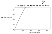
도 5는 뷰잉 각도의 함수로서 종래의 실버 스크린의 이득 곡선을 예시하는 그래프(500)이다. 이득 곡선(502)은 램버트 산란체의 BRDF에 대한 PP BRDF의 비룰 나타내고 도시된 바와 같이 편광에 대해 독립적이다. 이 스크린에 대해, 명도대비는 약 20°에서 절반으로 된다. PCR이 이득을 추적하기 때문에, 고 이득 스크린은 일반적으로 관찰된 크로스토크에서 최고의 공간 비균일성을 나타낸다. 5 is a
도 3 내지 도 5에 나타난 측정들은 종래의 실버 스크린을 이용한 경우의 것들을 나타내고, BRDF는 정반사 방향에서 입사각에 대해 거의 독립적이다. 이득 스크린의 PCR의 분자항은 따라서 주로 관찰 광선과 정반사 방향사이의 각도 차에 의존한다. 정반사 방향은 스크린 표면이 미러이었다면 광선이 지나갔을 방향에 대응한다. The measurements shown in Figures 3 to 5 represent those with conventional silver screens, and the BRDF is almost independent of the angle of incidence in the specular reflection direction. The molecular term of the PCR of the gain screen is thus mainly dependent on the angular difference between the observation light and the specular reflection direction. The specular reflection direction corresponds to the direction in which light rays would pass if the screen surface was a mirror.
크로스토크 누설항(분모)을 결정하는 인자들은 다음의 것들을 포함한다. Factors that determine the crosstalk leakage term (denominator) include the following:
1. 조명 파장보다 훨씬 작은 특징부로부터의 확산 산란에 기인한 탈편광. 이것은 나노크기정도의 거칠기를 갖는 반사 입자의 표면, 입자의 날카로운 에지, 아래에 있는 매트 기판을 노출시키는 코팅내의 공동(void)을 포함한다. 1. Depolarization due to diffuse scattering from features much smaller than the illumination wavelength. It includes voids in the coating that expose the surface of the reflective particles with nanoscale roughness, the sharp edges of the particles, and the underlying mat substrate.
2. 바인더 또는 첨가물질의 국부적 이방성에 기인한 편광 변화 2. Polarization change due to local anisotropy of binder or additive
3. 단일 표면으로부터의 (정반사)반사에서의 편광 변화 3. Change in polarization in (specular reflection) reflection from a single surface
4. 조명 방향에 대해, 광학 스케일로 급경사를 이룬 표면으로부터 생기는 다중 반사 4. Multiple reflections from steeply inclined surfaces on an optical scale with respect to the direction of illumination
본 발명은 종래의 실버 스크린과 같은 종래의 통계 표면과 연관된 명암대비면에서 제약사항을 극복하는 것을 추구한다. 본 발명에 따른 강화된 표면은 정반사 방향에서 과도한 반사도를 나타내지 않는, 전반사 분산 수단을 사용하여 더욱 바람직한 이득 프로파일을 제공할 수 있다. 상기 나열한 매커니즘에 기인한 기여는, 사실상 제거되지 않는다면, 거의 최소화될 수 있다. 더욱이, 경사 확률 밀도 함수에 대한 제어는 각각의 관찰자가 개선된 휘도 균일성을 통해 유사한 높은 명암비를 경험할 수 있도록 한다. 마지막으로, 강화된 표면은 투사 광을 좌석 위치로 지향시킴으로써 향상된 이미지 휘도를 나타낼 수 있도록 한다. 이것은 또한 표류광의 감소에 의해 색상 포화 및 이미지 명도대비를 개선시킨다. 본원에 설명된 프로세스를 이용하여, 스크린 재료는 가능한 최저비용에 의한 고품질로 제작될 수 있다. The present invention seeks to overcome the constraints in contrast associated with conventional statistical surfaces, such as conventional silver screens. The reinforced surface according to the invention can provide a more desirable gain profile using total reflection dispersion means, which do not exhibit excessive reflectivity in the specular reflection direction. Contributions due to the mechanisms listed above can be minimized if not virtually eliminated. Moreover, control over the gradient probability density function allows each observer to experience similar high contrast ratios through improved brightness uniformity. Finally, the enhanced surface allows for enhanced image brightness by directing the projection light to the seat position. It also improves color saturation and image brightness by reducing stray light. Using the process described herein, screen materials can be fabricated with high quality at the lowest possible cost.
인자 1 -- 조명 파장보다 훨씬 작은 특징부로부터의 확산 산란에 기인한 탈편광-- 은 약 수 나노미터 내지 수백 나노미터 크기 정도인 평면과 입사 광의 상호 작용과 연관된 탈편광을 나타낸다. 이 항의 기여는 (투사 및 관찰) 각도 공간에서 사실상 백색이고 편광 기준 벡터에 무감각한 경향이 있다. 교차 편광기 현미경으로 관찰했을 때, 기여는 백그라운드가 "불타오르는" 모양으로 나타난다. 이 항은 실질적으로 공동이 없고 이 레벨에서 특징부가 없는 엠보싱된 표면 토포그래피에 컨포멀한 고품질의 광학 코팅(낮은 rms 거칠기)을 사용함으로써 사실상 제거될 수 있다. Factor 1-Depolarization due to diffuse scattering from features much smaller than the illumination wavelength-- represents depolarization associated with the interaction of incident light with planes on the order of a few nanometers to several hundred nanometers in size. The contribution of this term tends to be substantially white in the angular space (projection and observation) and insensitive to polarization reference vectors. When viewed under a cross polarizer microscope, the contribution appears as a “burning” shape of the background. This term can be virtually eliminated by using a conformal high quality optical coating (low rms roughness) for embossed surface topography that is substantially free of voids and features at this level.
인자 2 -- 바인더 또는 첨가물질의 국부적 이방성에 기인한 편광 변화-- 는 광학적으로 두꺼운 "투명한" 코팅과 연관된다. 이러한 코팅은 편광의 국부 상태를 수정하는, 이방성을 가질 수 있다. 본 발명의 기술 교시는 미러형 금속 코팅으로부터의 단일 표면 반사를 이용하여 상기와 같은 기여를 제거할 수 있다. 임의의 추가 층은 실질적으로 지연이 제로인, 비교적 얇게 코팅된 낮은 복굴절을 갖는 산화물유형 유전체일 수 있다. Factor 2-change in polarization due to local anisotropy of the binder or additive-is associated with an optically thick "transparent" coating. Such coatings may have anisotropy, which modifies the local state of polarization. The technical teachings of the present invention can use a single surface reflection from a mirrored metal coating to eliminate such contributions. Any additional layer may be an oxide type dielectric with a relatively thin coated low birefringence, with a substantially zero delay.
인자 3 -- 단일 표면으로부터의 (정반사)반사에서의 편광 변화--은 로컬 반사 표면의 지오메트리를 나타나며 S 및 P 편광의 복합 반사에서의 근본적인 차이의 결과이다. PCR에서의 연관된 손실은 대부분의 시네마 환경에 대한 투사/관찰 사이의 일반적인 각도에 대해 비교적 중요하지 않지만, 그 밖의 많은 경우엔 중요할 수 있다. 금속 표면 위의 추가적인 컨포멀 유전체 코팅은 이러한 기여를 더욱 감소시킬 수 있다.Factor 3-change in polarization at (specular reflection) from a single surface--represents the geometry of the local reflective surface and is the result of a fundamental difference in the composite reflection of S and P polarized light. Associated losses in PCR are relatively insignificant for the general angle between projection / observation for most cinema environments, but may be significant in many other cases. Additional conformal dielectric coatings on the metal surface can further reduce this contribution.
인자 4 -- 조명 방향에 대해 급경사를 이룬 표면으로부터 생기는, 다중 반사-- 는 수직인 입사/관찰에서 발생할 수 있는(어떤 환경에선 최대치에 있음) 다중 반사를 나타낸다. 이 다중 반사는 일반적으로 경사도가 높은 확산 구조와 연관된다. 즉, 단일 반사 후 전방으로 계속 진행하거나, 또는 단일 반사 후인접한 구조를 뛰어 넘지 않은 광선은 2차 반사를 겪는다. 이러한 이벤트들간의 평균 자유 경로는 반사 특징부 크기보다 훨씬 클 수 있고 이에 따라 기타 바람직하지 않은 (이미지 품질) 결과를 초래한다. 이중 반사된 광선은 매우 변경된 편광 상태를 가질 수 있고, 따라서 편광 명암비를 열화시킨다. 더욱이, 이러한 반사의 영향은 하기에 설명하는 바와 같이 편광 기준 벡터의 함수이다.
Factor 4-multiple reflections, which arise from surfaces that are steeply inclined to the direction of illumination, represents the multiple reflections that can occur (at maximum in some environments) at normal incidence / observation. This multiple reflection is generally associated with a high gradient diffusion structure. That is, rays that continue forward after a single reflection, or do not jump beyond the adjacent structure after a single reflection, undergo secondary reflection. The average free path between these events can be much larger than the reflective feature size, resulting in other undesirable (image quality) results. Double reflected rays can have very altered polarization states, thus degrading the polarization contrast ratio. Moreover, the effect of this reflection is a function of the polarization reference vector, as described below.
확산 산란Diffuse scattering
인자 1은 확산 산란과 연관된 높은 공간 주파수에서 거의 또는 전혀 기여를 포함하지 않는 연속적인 마이크로 반사 구조를 이용하여 사실상 제거될 수 있다. 이론적으로, 이것은 Morris등에 의해 미국 특허 제 7,033,736호(본원에 참조 문헌으로서 포함됨)에 설명된 일부 디자인 성능을 이용하여 부분적으로 달성될 수 있고, 이 문헌에서 임의 경사 확률 밀도 함수가, 전형적으로 확산 산란체인, 전반사 수단을 이용하여 발생될 수 있다. 또한, 이 구조는 성능을 손상시키지 않고 매트 외양을 보존하도록 하는 크기, 위치 경사 및 높이면에서 의사 난수 분포를 가질 수 있다.
실제적인 관점에서, 본 발명의 강화된 구조(확산기)는 제조 환경에서 일관성있게 대량 생산되는 것이 바람직하다. 이것은 본원에 설명된 것과 일치하는 생성 커널의 롤투롤(roll-to-roll) 엠보싱 공정을 수반한다. 더욱이, 후속하는 코팅은 예를 들어, 증착 또는 스퍼터링에 의해 마찬가지로 고 품질 레벨로 도포되는 것이 바람직하다. 본 발명이 시네마 환경에서 확산기/스크린의 사용을 설명하지만, 이 확산기/스크린은 홈시어터, 게이밍 시스템, 가상 현실, 비행 시뮬레이터등을 포함하지만 이에 한정되지 않는 응용분야에서 비주얼 매체가 뷰잉되는 기타 환경에도 대아적으로 사용될 수 있다.In practical terms, the enhanced structure (diffuser) of the present invention is preferably mass produced consistently in a manufacturing environment. This involves a roll-to-roll embossing process of the production kernel consistent with that described herein. Moreover, it is preferred that the subsequent coating is likewise applied at a high quality level, for example by deposition or sputtering. Although the present invention describes the use of a diffuser / screen in a cinema environment, the diffuser / screen may also be used in other environments where visual media are viewed in applications including, but not limited to, home theaters, gaming systems, virtual reality, flight simulators, and the like. Can be used alternatively.
현재 통계 표면(예를 들어, 종래의 실버 스크린)은 예외없이 바람직한 100% 보다 낮은 반사기 구경비(fill-factor)를 갖는데, 여기서 구경비는 전체 구역에 대한 금속화된 구역의 비인 것으로 정의된다. 여기에서, 금속화된 구역은 0의 투과율을 갖는 것으로 가정한다. 그러나, 반사기가 부분적으로 투과시키는 경우, 또 다른 탈편광 매커니즘이 작동될 수 있다. 실버 스크린에서 더욱 일반적으로, 코팅내의 작은 핀홀은 (흔히 백색인) 탈편광 매트 기판을 노출시킨다. 핀홀의 존재가 불가피한 경우엔, 고흡수율의 베이스 기판(예를 들어, 검은색 매트)을 사용하는 것이 바람직한데 이는 이 기판은 탈편광된 광의 투과를 상당히 감소시키기 때문이다. 예를 들어, 그라비어 인쇄 공정을 사용하여 제작된 스크린은 일반적으로 적은 구경비를 가지므로, 그 PCR은 기판 탈편광에 의해 좌우된다. Current statistical surfaces (eg conventional silver screens) have, without exception, a desirable reflector fill-factor of less than 100%, where the aperture ratio is defined as the ratio of the metalized zone to the total zone. Here, it is assumed that the metallized zone has a transmission of zero. However, if the reflector partially transmits, another depolarization mechanism can be activated. More generally in silver screens, small pinholes in the coating expose (often white) depolarized mat substrates. If the presence of pinholes is unavoidable, it is desirable to use a high absorption base substrate (e.g. black matte) because this substrate significantly reduces the transmission of depolarized light. For example, screens fabricated using the gravure printing process generally have a low aperture ratio, so the PCR is dependent on substrate depolarization.
실제적인 구현에서, 확산 산란은 흔히 핫스폿을 제거하려는 시도에 의해 생긴다. 면이 통계 표면과 함께 기판에 평행하게 놓이는 경향으로 인해, 정반사 방향으로의 반사를 무효시키도록 하려는 노력을 해야한다. 이것은 확산 산란을 증가시킴으로써 행해질 수 있지만, 휘도 및 PCR을 희생시킨다. 본 발명에 따라, 확률 밀도 함수는 정반사 방향에 근사하게 균일한 방식으로 강화된다. 이것은 편광이 보존될 수 있도록 하는 동시에 스크린 휘도를 증가시킨다.
In practical implementations, diffuse scattering is often caused by attempts to remove hot spots. Due to the tendency of the face to lie parallel to the substrate with the statistical surface, efforts should be made to negate the reflection in the specular direction. This can be done by increasing diffusion scattering, but at the expense of brightness and PCR. According to the invention, the probability density function is enhanced in a uniform manner approximating the direction of specular reflection. This increases the screen brightness while allowing polarization to be preserved.
영화관 Movie Theaters 지오메트리Geometry 및 반사에서 편광 변화 Change in polarization and reflection
최적화된 통계 표면 설계에서 중요한 양상은 영화관 객석과 연관된 지오메트리의 범위를 완전히 이해하는 것이다. 요즘 영화관의 영사실에서, 투사 렌즈는 스크린에 대해 수평방향으로 (명목상으로) 중심에 위치하지만, 일반적으로는 수직방향에서 중심보다 위에 위치한다. 이것은 오프셋트가 제로 내지 스크린의 1/2 보다 큰 범위일 수 있다. 스크린은 (최적으로는) 투사 거리와 같거나 투사 거리를 넘는 곡률 반경을 갖는 (수직방향에 대해) 단일 축 곡률을 갖는 것이 일반적이다. 이것은 사실상 1.3 이상의 이득을 갖는 스크린을 사용할 때 SMPTE 호환에 대한 요구조건이다.An important aspect of optimized statistical surface design is to fully understand the range of geometry associated with the cinema seat. In modern movie theaters, the projection lens is centered horizontally (nominally) relative to the screen, but generally above the center in the vertical direction. This may range from zero to more than one half of the screen. The screen typically has a single axis curvature (relative to the vertical direction) with a radius of curvature (optimally) equal to or greater than the throw distance. This is actually a requirement for SMPTE compatibility when using screens with gains of 1.3 or higher.
전방 구역은 약 8°내지 10°로 경사지고, 이보다 큰 후방 구역은 약 20°내지 22°로 경사진, 두 구역에 착석하게 되어 있는 스타다움을 찾는 것이 전형적이다. 전방 구역은 일반적으로 (스크린처럼) 만곡되어 있고, 반면에 후방 구역은 일반적으로 장방형이다. 프로젝터에 가장 가까운 행에 추가의 좌석이 빈번하게 추가되는데, 이는 후방 구역의 유효 폭을 증가시킨다. 전형적인 영화관에서, 평균 투사비(스크린 폭에 대한 투사 거리의 비)는 약 1.8이다. It is typical to find a stare that is seated in two zones, in which the front zone is inclined at about 8 ° to 10 ° and the larger rear area is inclined at about 20 ° to 22 °. The front zone is generally curved (like a screen), while the rear zone is generally rectangular. Additional seats are frequently added to the row closest to the projector, which increases the effective width of the rear zone. In a typical cinema, the average throw ratio (ratio of throw distance to screen width) is about 1.8.
용어 정의와 관련하여, 성능은 가상의 "이상적인 뷰어"의 관점에서 상이한 관찰 위치에 대해 설명될 수 있다. 이상적인 뷰어는 백색 프레임의 피크 휘도가 (이득 스크린을 사용할 때)스크린의 중심에서 발생하는 좌석 위치를 표현한다. 그 밖의 관심있는 위치는 시스템이 만족스럽게 수행해야 할 주위 좌석을 포함한다. 이 주위 좌석들은, 상기 설명한 기타 지리적 고려사항과 함께 고려되는, 확산 궤적을 정의한다. Regarding the term definition, performance may be described for different viewing locations in terms of a virtual “ideal viewer”. The ideal viewer represents the seat position where the peak luminance of the white frame occurs when centering the screen (when using a gain screen). Other positions of interest include the surrounding seats that the system should perform satisfactorily. These surrounding seats define the spreading trajectory, which is considered along with the other geographical considerations described above.
랜덤하게 21개의 영화관 객석에 대해 테스트한 결과, 축 방향 광선의 평균 수직 오프셋 각도는 약 8도 정도 감소하였다. 수직 오프셋은 정반사 방향을 하향으로 편향시키는데, 이는 이득 스크린에서 휘도에 대해 유익한 것이다. 적합하게 설계되었을 때, 이것은 이상적인 뷰어를 좌석의 중앙 위치에 둔다. 이와 반대로, 제로 오프셋트를 갖는 경우에, 이득 스크린에서 최적 뷰잉 위치는 프로젝터가 있는 위치인데, 이는 명백히 실제적이지 못하다. 바람직한 이상적인 뷰어와 연관된 각도 및 프로젝터 오프셋트에 좌우되어, 확산 각도에서의 편향은 본 발명에 따라 확산기 설계에 고려사항으로 포함될 수 있다.Randomly tested 21 theater seats, the average vertical offset angle of the axial light beam decreased by about 8 degrees. The vertical offset biases the specular reflection direction downwards, which is beneficial for luminance in the gain screen. When properly designed, this puts the ideal viewer in the center of the seat. In contrast, with zero offsets, the optimal viewing position in the gain screen is the position where the projector is, which is obviously not practical. Depending on the angle and projector offset associated with the preferred ideal viewer, deflection in the diffuse angle can be included in the diffuser design in accordance with the present invention.
최악의 경우에 해당하는 뷰잉 각도는 주변 좌석(또는 시스템이 정확하게 수행해야 할 좌석의 서브셋트에 대해)과 연관된다. 이 좌석들은 뷰잉 궤적을 정의한다. 휘도 및 명도대비에 대한 이상적인 환경하에서, 본 발명에 따라, 어떠한 광도 확산 궤적 외부로 투사되지 않는다. 더욱이, 최적화된 편광 명암비는 단지 단일한 반사만이 확산 궤적내에서 발생할 것을 필요로 한다. 다중 반사가 발생하는 경우에, 다중 반사는 바람직하게 확산 궤적 외부라는 반사 조건에 대해 발생해야 한다. The worst case viewing angle is associated with the surrounding seat (or for a subset of seats that the system should perform correctly). These seats define the viewing trajectory. Under ideal circumstances for brightness and contrast, according to the invention, no light is projected out of the diffusion trajectory. Moreover, the optimized polarization contrast ratio requires that only a single reflection occur within the diffusion trajectory. If multiple reflections occur, multiple reflections should preferably occur for a reflection condition outside of the diffusion trajectory.
도 6A 및 도 6B는 상이한 뷰잉 위치에서 특정한 객석의 뷰잉 궤적에 대한 대표적인 극좌표 그래프(600 및 650)를 각각 나타낸다. 도 6A는 전방 좌측 좌석(예를 들어, 도 1의 뷰잉 위치(132))에서 스크린의 주변을 추적함으로써 정의된, 관찰 광선의 각도를 (글로벌 좌표계에서) 표현하는 선도(602)를 나타낸다. 도 6B는 후방 좌측 좌석(예를 들어, 도 1의 뷰잉 위치(134))에 대한 대응하는 선도(652)를 나타낸다. 이 경우, 관찰 광선의 각도를 나타낸 선도(652)는 관찰 광선의 각도를 나타낸 선도(602)에 포함된다. 일반적인 스타디움 좌석 배열에서, 후방 좌석은 스크린의 하부에 대응하는 궤적의 일부를 정의한다. 6A and 6B show representative polar coordinate
도 7은 21개 극장 객석에 대한 랜덤 샘플링에 대해, 상기 설명한 도 6A 및 도 6B와 유사한, 뷰잉 궤적을 도시하는 극좌표 그래프(700)를 나타낸다. 극좌표 데이터(704)는 주변부(702)에 대해 포함되고, 이 주변부는, 수직 방향에 대해 조명/뷰잉 조건 대칭을 위해, 수직 방향에 또한 대칭인 확산 궤적을 정의한다. 설계 목적은 모든 뷰잉 위치에 임의의 안전을 위한 마진 예를 들어, 5도를 더한 것을 포함하는 뷰잉 궤적을 포함하기 위해, 주변부(702)에 의해 정의된 지역내로 실질적으로 확산을 제한하는 것이다. FIG. 7 shows a
하기에 설명하는 분석에서, 스크린은 거시적 스케일로 볼 때 사실상 공평면을 이루지만, 경사 확률 밀도 함수에 따른 방향에서 랜덤하게 분포된, 마이크로 반사기의 더미(collection)를 포함한다고 가정한다. 로컬 좌표계는 본원에선 투사 광선 벡터 및 관찰 광선 벡터에 의해 정의된다. 이것은 로컬 면 법선 벡터를 포함하는, 로컬 입사 평면을 정의한다(여기서 면 모델은 일반적으로, 원하는 표면이 연속하는 마이크로 반사 특성을 갖는 경우에도, 조명을 위해 사용된다). 편광은 실질적으로 스크린에 의해 보존되기 때문에, 면에 의해 반사된 광은 정반사에 의한 결과 인 것으로 가정하는 것이 합리적이다. 원하는 방향에서 면이 존재할 가능성은, 스크린 이득과 관련되는, 2차원 경사 확률 밀도 함수에 의해 주어진다. In the analysis described below, it is assumed that the screen comprises a collection of micro reflectors, which are virtually coplanar when viewed on a macro scale, but which are randomly distributed in the direction according to the gradient probability density function. The local coordinate system is defined herein by the projection ray vector and the observation ray vector. This defines the local incidence plane, including the local face normal vector (where the face model is generally used for illumination, even if the desired surface has continuous microreflective properties). Since polarization is substantially preserved by the screen, it is reasonable to assume that the light reflected by the face is the result of specular reflection. The likelihood of faces in the desired direction is given by the two-dimensional gradient probability density function, which is related to the screen gain.
로컬 입사 평면은 또한 프레스넬 반사 등식에 따르는, 로컬 S 및 P 벡터(또는 로컬 고유 벡터)를 정의한다. 이 경우, 기능적 코팅은 일반적으로, 복소 굴절율을 가지며 따라서 흡수성을 나타내는, 금속(예를 들어 , 알루미늄)이다. "면 영역"은 조명 파장에 대해 크다고 가정하면(또는 더욱 현실적으로는, 경사는 파장의 스케일로 느리게 변동한다고 가정하면), 광은 표면으로부터 정반사하여, 편광을 보존한다고 간주될 수 있다. 따라서, 일반적으로 편광 상태(SOP;state of polarization)의 변화는 S 및 P와 연관된 개별적인 복소 반사 계수에 기인하여 발행하지만, 실질적으로 이벤트와 연관된 탈편광은 전혀 없다. The local incidence plane also defines local S and P vectors (or local eigenvectors), according to Fresnel reflection equations. In this case, the functional coating is generally a metal (eg, aluminum), having a complex refractive index and thus absorbing. Assuming that the "plane area" is large with respect to the illumination wavelength (or more realistically, assuming that the slope fluctuates slowly on the scale of the wavelength), light can be considered to be specularly reflected from the surface, preserving polarization. Thus, changes in the state of polarization (SOP) generally occur due to the individual complex reflection coefficients associated with S and P, but substantially no depolarization associated with the event.
선형으로 편광된 입사 광이 S 및 P 투사를 포함하는 특정한 경우를 고려해 보자. 반사파에서의 위상차는 타원율을 유도하는 경향이 있는 반면에 반사도의 차이는 방향을 회전시키는 경향이 있다. 최악의 방위 각도(면 입사 평면에 대해 ±45°에서의 편광)에서의 선형 편광기 기반 3D 시스템, 또는 임의의 방위 각도에서의 원형 편광기 기반 시스템에 대해, 편광 명암비에 기여하는 프레스넬 반사는 하기의 등식과 같이 주어진다. Consider a particular case where linearly polarized incident light includes S and P projections. The phase difference in the reflected wave tends to induce an ellipticity, while the difference in reflectivity tends to rotate the direction. For a linear polarizer-based 3D system at the worst azimuth angle (polarization at ± 45 ° to the plane of incidence plane), or a circular polarizer-based system at any azimuth angle, Fresnel reflections that contribute to the polarization contrast ratio are Is given as an equation.

여기서 ![]()
![]()
![]()
![]()
기본적으로, 면 입사 각도는 (중앙에 있는 프로젝터에선) (무한 투사 거리를 갖는, 45°미만이어야 하고 예를 들어, 편평한 스크린) 뷰어는 스크린의 중앙에 위치하여야 한다. 보다 일반적으로는 극장 객석에서, 최악의 경우에 해당하는 뷰어와 연관된 면 입사 각도는 35°미만이다. Basically, the plane angle of incidence should be less than 45 ° (for example, a flat screen) with an infinite projection distance (on a projector in the center) and the viewer should be centered on the screen. More generally, in theater seating, the worst case incident angle associated with the viewer is less than 35 °.
도 8은 면 입사 각도의 함수로서 원형 편광(또는 선형 편광의 최악의 방위각)에 대한 프레스넬 PCR의 그래프이다. 명도대비(802)는 25°미만의 각도에 대해 1,000:1 이상이고(이는 대부분의 청중을 차지한다), 나머지 명도대비는 35°까지에 대해 270:1 이상이다. 따라서, 프레스넬 기여는 현재 영화관 환경에서 상대적으로 작다. 8 is a graph of Fresnel PCR versus circularly polarized light (or worst azimuth of linearly polarized light) as a function of plane incidence angle.
상대적 기여에 관해(또다시 일차항에 관해), 반사도 차이만에 기인한 명도대비는 35°에서 24,000:1이고, 반면에 반사 지연에만 연관된 명도대비는 273:1이다. 따라서, 프레스넬과 연관된 명도대비의 손실은 대부분 S와 P간의 위상 편이에 기인한다. S와 P의 위상에 더욱 밀접하게 매치할 기회가 존재하는 한편, 컨포멀 투명 유전체층을 금속 위에 추가함으로써 (동시에 자연 산화막의 성장을 방해하는 역할을 함) 전반적인 반사도를 증가시킬 기회가 존재한다. 이것은 일반적으로 소위 "보호 알루미늄" 미러 코팅으로 행해진다. Lippey에 허여된 미국 특허 제 7,110,175호(본원에 참조 문헌으로 포함됨)는 S와 P를 동일 반사도로 반사시키기 위해 유전체층을 사용함으로써 반사도 차이를 해결하는 알루미늄 증착을 개시한다. 그러나 Lippey는 명도대비가 반사도 차이 보단 위상 차에 의해 더 많이 영향을 받는다는 것을 알지 못했다. 탈편광은 S 및 P 간의 차이의 결과에 의한 것으로서만 가정되기 때문에, 명도대비에 대한 자연 물체는 로컬 입사각도를 최소화하기 위한 것이고, 따라서 높은 이득을 갖는다. 그러나, 본원에 설명된 바와 같이, 본 발명자들은 지배적인 탈편광 매커니즘은, Lippey는 언급조차 하지 않은, 다수의 산란 이벤트라는 것을 증명하였다. 다른 말로 하면, Lippey는 명도대비 성능에 기여하는 지배적인 매커니즘 또는 그러한 명도대비 성능의 최적화를 위한 기술을 알지 못한다. 또한, Lippey가 확인한 두 번째 목적은 S 및 P 편광의 진폭 반사를 매치시키는 것이다. 그러나, 본 발명이 개시한 기술에선, S 및 P 반사도의 진폭을 매치시키는 것과 두 개의 성분간의 위상 차이를 최대화하는 것이 가능하며, 이에 따라 편광 보존 특성에서 우수한 성능을 제공한다. With respect to relative contributions (again, with respect to the first term), the contrast due to only the difference in reflectivity is 24,000: 1 at 35 °, while the brightness relative to reflection delay only is 273: 1. Thus, the loss of brightness associated with Fresnel is mostly due to the phase shift between S and P. While there is an opportunity to more closely match the phases of S and P, there is an opportunity to increase the overall reflectivity by adding a conformal transparent dielectric layer over the metal (which at the same time serves to hinder the growth of the native oxide film). This is generally done with a so-called "protective aluminum" mirror coating. U. S. Patent No. 7,110,175 to Lippey, incorporated herein by reference, discloses aluminum deposition that resolves reflectance differences by using a dielectric layer to reflect S and P with the same reflectivity. Lippey, however, did not know that brightness was more affected by the phase difference than the difference in reflectivity. Since depolarization is only assumed as a result of the difference between S and P, the natural object for contrast is to minimize the local angle of incidence and therefore has a high gain. However, as described herein, the inventors have demonstrated that the dominant depolarization mechanism is a number of scattering events, not even mentioned by Lippey. In other words, Lippey does not know the dominant mechanism that contributes to brightness performance or techniques for optimizing such brightness performance. Also, Lippey's second objective is to match the amplitude reflections of S and P polarized light. However, in the technique disclosed by the present invention, it is possible to match the amplitudes of the S and P reflectivity and to maximize the phase difference between the two components, thus providing excellent performance in polarization preservation characteristics.
빈번하게, 유전체 오버코트는 내구성을 제공하고 반사도를 개선하기 위해 금속 미러에 증착된다. 베어 알루미늄(bare aluminum)이 코팅되지 않았으면, 긁히기 쉽고 결국엔 얇은 층(70-90Å)의 자연 산화물(Al2O3)을 형성하게 될 것이다. 자연 산화물(굴절율 n=1.66)은 시간에 대해 반사도가 감소하는 경향을 나타낼 것이다. 그 대신에, 광학 두께의 약 1/4파 길이인 MgF2(n=1.38)의 층이 베어 알루미늄에 증착되면, 반사도는 수 퍼센트 정도 증가될 수 있다. MgF2는 유전체 오버코트에 대한 이상적인 선택물질이지만, 실질적인 개선은 SiO2와 같은 그 밖의 저 굴절율의 유전체를 이용하여 획득될 수 있다. 두 경우 모두에서, 주 제약사항은 S 와 P 반사파간의 복소 위상차를 최소화하는 것이다.Frequently, dielectric overcoats are deposited on metal mirrors to provide durability and improve reflectivity. If bare aluminum is not coated, it will be easily scratched and will eventually form a thin layer (70-90 μs) of natural oxide (Al 2 O 3 ). Natural oxides (refractive index n = 1.66) will tend to decrease in reflectivity over time. Instead, if a layer of MgF 2 (n = 1.38), about 1/4 wave length of optical thickness, is deposited on bare aluminum, the reflectivity can be increased by a few percent. MgF 2 is an ideal choice for dielectric overcoat, but substantial improvements can be obtained using other low refractive index dielectrics such as SiO 2 . In both cases, the main constraint is to minimize the complex phase difference between S and P echoes.
본 발명에서, 편광 보존은 효율을 증가시키는 것보다 더욱 중요할 수 있다. 상기 설명한 바와 같이, 박막 보상을 통해 S 와 P 성분간의 위상 차를 감소시키는 것은 편광을 보존하는 데에 도움을 준다. 임의 두께 및 굴절율의 유전체막은, 589nm에서 PCR이 되는, 성능 메트릭을 이용하여(여기서 입력 편광은 입사 평면에 대해 45°에 있다) 굴절율이 최소로 될 때(예를 들어, MgF2를 이용했을 때) 최선의 결과를 산출한다. 70Å 두께의 자연 산화물이 사용될 때, 면 입사 각도 35°에서의 PCR은 139:1(이는 베어 알루미늄보다 낮다)이다. 두께가 0.34 파장길이인 MgF2 층을 추가하는 것은 23,915:1의 명암비를 산출한다. 28°에서 명암비는 보상된 경우(1,934:1)에 비해 더 낮지만, 여전히 명암비는 보상되지 않은 경우(360:1) 보다 매우 높은 상태로 존재한다. 작은 각도에 대해, 명암비는 일반적으로 증가하지만, 보상된 경우는 보상되지 않은 경우에 비해 적어도 3배 만큼 큰 상태로 존재한다. In the present invention, polarization preservation may be more important than increasing efficiency. As described above, reducing the phase difference between S and P components through thin film compensation helps to preserve polarization. Dielectric films of arbitrary thickness and index of refraction are subjected to performance metrics, which are PCR at 589 nm (where the input polarization is at 45 ° to the plane of incidence) when the refractive index is minimized (e.g., using MgF 2) . ) Yield the best results. When 70 nm thick native oxide is used, the PCR at the plane incidence angle of 35 ° is 139: 1 (which is lower than bare aluminum). Adding an MgF 2 layer with a thickness of 0.34 wavelengths yields a contrast ratio of 23,915: 1. At 28 ° the contrast ratio is lower than the compensated (1,934: 1), but still the contrast ratio is much higher than the uncompensated (360: 1). For small angles, the contrast ratio generally increases, but the compensated case exists at least three times larger than the uncompensated case.
기울어진 면(tilted facet)은 선형 고유편광(eigenpolarization)을 갖기 때문에, 선형 편광에 기초한 시스템의 성능은 방위각에 좌우된다. 입력 편광이 면 입사 평면에 포함된다면, 편광은 반사에서 보존된다. 이 매커니즘이 명암비를 결정하는 데에 있어서 중요하다면, 전체 성능을 최적화하도록 안경을 선택할 수 있다. 예를 들어, 스크린 모서리부는, 0/90°방위각보다 ±45°방위각에 더욱 근사하는 경향이 있을 수 있는, 최대 면 입사 각도에 대응하는 경향이 있다. 이러한 환경에서, ±45°선형 편광 안경을 기반으로 한 시스템이 사용될 수 있다. 원형 편향을 l반으로 하는 시스템에 대해, 임의의 방위각에 대한 반사에서의 편광 변화에서 완화되지 않는데, 이는 명암비는 방위각에 무관하기 때문이다. 명암비가 다수 반사파에 의해 지배되는 경우에, 상기한 요인은 관련된 설계 고려사항이 아닐 수도 있다.
Since the tilted facet has linear eigenpolarization, the performance of the system based on linear polarization depends on the azimuth angle. If the input polarization is included in the plane of incidence, the polarization is preserved in reflection. If this mechanism is important in determining the contrast ratio, you can choose glasses to optimize the overall performance. For example, the screen edges tend to correspond to the maximum plane incidence angle, which may tend to be closer to ± 45 ° azimuth than the 0/90 ° azimuth. In this environment, a system based on ± 45 ° linearly polarized glasses may be used. For a system with half the circular deflection, the polarization change in reflection for any azimuth is not mitigated because the contrast ratio is independent of the azimuth. In cases where the contrast ratio is dominated by multiple reflected waves, the above factors may not be related design considerations.
이중 반사Double reflection
스크린 구조에 따라, 단일 반사가 크로스토크에 가장 중요한 영향을 인자가 아닐 수도 있은 후에 편광이 변할 수 있다. 웨이브프론트 테크놀로지(Wavefront Technologies)사에 의해 제작된 확산기와 같은 고 지향성 확산기는 제2 반사를 일으키는 경향이 있는 경사가 매우 심한 리지를 갖는다. 교차 편광 현미경하에서, 시판중인 규격품 홀로그래픽 확산기는 정상적으로 조명되어 검출되었을 때 역반사에로 인해 선형 고유 편광을 나타낸다. 정상적으로는 투과에 사용되지만 테스트를 위해 알루미늄으로 코팅된 3개 샘플 제품에서, 모든 샘플은 직교 방향 보단 다른 방향에서 실질적으로 더 많이 분산되었다(8°/21°, 10°/68°,12°/44°). 코팅된 샘플들은 입력 편광이 구조물 축에 평행일 때는 명암비가 수백 대 일이었지만 샘플이 회전되었을 때는 명암비가 45°방위각에서 단지 수십 대 일로 상당히 낮았다는 것을 증명하였다. 이 측정들은 역반사 배열에서 행해졌음을 알아야 한다. Depending on the screen structure, the polarization may change after a single reflection may not be the most important effect on crosstalk. High directional diffusers, such as diffusers manufactured by Wavefront Technologies, Inc., have very steep ridges that tend to cause second reflections. Under cross polarization microscopy, commercially available standard holographic diffusers exhibit linear intrinsic polarization due to retroreflection when detected under normal illumination. In the three sample products normally used for permeation but coated with aluminum for testing, all samples were substantially more dispersed in the other direction than the orthogonal direction (8 ° / 21 °, 10 ° / 68 °, 12 ° /). 44 °). The coated samples demonstrated that the contrast ratio was hundreds of units when the input polarization was parallel to the structure axis, but the contrast ratio was significantly low at only 45 degrees of azimuth when the sample was rotated. It should be noted that these measurements were made in a retroreflective arrangement.
금속 플레이크 스크린과 같은 통계 표면은 이중 반사하기가 쉽다. 흔히, 면쌍들간의 자유 평균 경로는 실제 반사하는 특징부 크기보다 상당히 크다. 스크린 샘플이 역반사 배열에서 교차 선형 편광기 현미경하에서 회전되었을 때, 면 쌍의 휘도는 같은 비율로 변화하는 것이 관찰될 수 있다. 이것은 대향하는 전파 방향에서 나오는 편광 변환된 광에 기인하는 것일 수 있다. 고유 방향을 따라, 사기 쌍들은 매우 소멸된다. 역반사에 의한 높은 편광 변환 정도로 인해, 면 쌍은 ±45°방위각에서 매우 밝았다. 면 쌍의 유효 지오메트리는 흔히 매우 유사한데(면들의 오버랩 영역에 의해 좌우된다), 이는 면 쌍을 용이하게 식별하는 또 다른 인자이다. Statistical surfaces, such as metal flake screens, are easy to double reflect. Often, the free mean path between face pairs is significantly larger than the actual reflecting feature size. When the screen sample is rotated under a cross linear polarizer microscope in a retroreflective arrangement, it can be observed that the brightness of the face pairs changes at the same rate. This may be due to the polarized light converted from the opposite propagation direction. Along the inherent direction, fraud pairs are very extinct. Due to the high degree of polarization conversion by retroreflection, the face pairs were very bright at ± 45 ° azimuth. The effective geometry of a face pair is often very similar (depending on the overlap area of the faces), which is another factor in easily identifying face pairs.
역반사 배열은 휘도 관점에서 잠재적인 이점을 갖는다. 즉, 피크 확산의 방향이 입사 방향에 반대이면, 프로젝터로부터의 광은 청중을 향해 투사되는 경향이 클 것이다. 구슬 스크린(Beaded screen)은 예를 들어, 고양이의 눈 역반사기와 같은 기능상의 이점을 가질 수 있다. 이 스크린들은 자기 보정 특성을 가지기 때문에, 역반사기는 광을 최적으로 분산시키는 수단으로서 확산 특성에 대한 로컬 제어 필요성을 사실상 제거한다. 그러나, 그러한 역반사가, 특정한(예를 들어,코너 큐브) 역반사기에서 종종 발생하는 바와 같은, 편광을 훼손시키지 않도록 주의를 기울여야 한다. 면쌍(facet-pairs)으로부터의 이중 반사의 경우에, 편광은 실질적으로 직교 상태로 변환된다. Retroreflective arrangements have potential advantages in terms of luminance. That is, if the direction of peak spreading is opposite to the direction of incidence, the light from the projector will tend to be projected toward the audience. Beaded screens may have functional advantages such as, for example, cat's eye retroreflectors. Because these screens have self-correcting properties, retroreflectors virtually eliminate the need for local control of the diffusing properties as a means of optimally dispersing light. However, care must be taken not to compromise polarization, as such retroreflection often occurs in certain (eg, corner cube) retroreflectors. In the case of double reflection from facet-pairs, the polarization is converted to a substantially orthogonal state.
지난 날엔, 렌티큘러형 주기적 구조는 수직 방향 보단 수평 방향으로 더 많이 분산시키기 위해 영화 스크린에서 사용되었었다. 구조화된 표면이 광을 수직 방향 보단 수평 방향으로 더 많이 분산시키기 위해 사용되는 경우에 -이 경우엔 제2 반사를 일으키기 쉬움- 0/90°편광 안경에 기초한 시스템이 사용될 수 있다. 더욱 가능하게는, 제2 반사를 일으키기 쉬운 스크린 구조는 적합하게 기능하지 않을 것이다.
Last day, lenticular periodic structures were used on movie screens to spread more in the horizontal direction than in the vertical direction. Where a structured surface is used to disperse more light in the horizontal direction than in the vertical direction—in this case easily prone to second reflection—a system based on 0/90 ° polarized glasses may be used. More preferably, screen structures susceptible to second reflection will not function properly.
PCRPCR 에 대한 각각의 항의 기여Each claim's contribution to
특정한 측정값은 PCR에 대한 각각의 물리적 매커니즘의 기여를 추출하는 데에 사용될 수 있다. 상기 설명한 내용에 기초하여, 확산 산란 항은 각도 공간에서 백색일 수 있고, 편광 기준 벡터에 독립적이다. 이것은 배경 누설 항이다. 따라서, PCR 결과 대 면 입사각은 선형 및 원형 편광에 대해 동일해야 한다. 동일하지 않다면, 또다른 물리적 매커니즘이 크게 기여할 수도 있다. Specific measurements can be used to extract the contribution of each physical mechanism to the PCR. Based on the above description, the diffuse scattering term may be white in angular space and is independent of the polarization reference vector. This is the background leakage term. Therefore, the angle of incidence facing the PCR results should be the same for linear and circular polarizations. If not the same, another physical mechanism may contribute significantly.
프레스넬 기여는 역반사방향(단일 반사에 대해)에서 제로인데, 이는 면 입사각이 20°에 근접함에 따라 크게 되고, 각도가 증가함에 따라 점점 커진다. 입력이 면 입사 평면에 평행/수직일 때 그리고 ±45°에서 최대일 때 사라지는, 명백히 편광에 종속적이다. PCR에 대한 기여는 원형 편광을 사용할 때는 방위각에 독립적이다. 따라서, 큰 입사각에서 선형 PCR 결과가 강한 방위각 함수이면(또는 선형 PCR과 원형 PCR간에 상당한 차이가 있으면), 프레스넬 항은 중요할 수 있다. 이것은 다수 반사로부터의 기여가 상기한 바와 같은 큰 각도에선 상대적으로 덜 중요하게 된다고(또는 분리될 수 있다고) 가정한다. The Fresnel contribution is zero in the retroreflective direction (for a single reflection), which becomes larger as the plane angle of incidence approaches 20 ° and becomes larger as the angle increases. It is clearly polarization dependent, disappearing when the input is parallel / vertical to the plane of incidence plane and maximum at ± 45 °. The contribution to PCR is independent of azimuth when using circular polarization. Thus, if the linear PCR result is a strong azimuth function at large incidence angles (or if there is a significant difference between linear PCR and circular PCR), Fresnel terms may be important. This assumes that the contribution from multiple reflections becomes relatively less important (or can be separated) at large angles as described above.
선형 및 원형 기준 벡터가 역반사 방향에서 상이한 PCR을 제공하는 경우에, 그 이유는 마찬가지로 이중 반사이다. 통계 표면에선, 경사 확률 밀도가 방위각에서 균일한 경우에, 이중 반사 이벤트일 가능성은 마찬가지로 방위각에서 균일하다. 원형 편광에서, PCR에 대한 기여는 따라서 방위각에서 균일하다. 선형 편광의 방위각 종속성 때문에, 전체 방위각에 대해 평균화된 PCR에 대한 기여는 원형 편광의 경우의 절반이다. If the linear and circular reference vectors provide different PCR in the retroreflection direction, the reason is likewise double reflection. On the statistical surface, if the gradient probability density is uniform at the azimuth, then the likelihood of a double reflection event is likewise uniform at the azimuth. In circular polarization, the contribution to PCR is therefore uniform at azimuth. Because of the azimuthal dependency of linear polarization, the contribution to PCR averaged over the entire azimuth is half of that for circular polarization.
이 기여를 테스트하는 방법으로서, 편광에 민감한 BRDF 측정이 선형인 경우 및 원형인 경우에 대해 행해졌는데, 여기서 선형인 경우 고유 방향(Eigen-direction)을 따른다. As a method of testing this contribution, the polarization sensitive BRDF measurements were made for the linear and the circular case, where the linearity follows the eigen-direction.
도 9는 선형인 경우의 명암비(902)가 160:1을 넘고, 원형인 경우의 명암비(904)는 단지 110:1임을 나타내는 그래프이다. 이 차이는 역반사 방향을 따라 관찰되기 때문에, PCR에 대한 기여에서의 임의의 차이는, 원형의 경우의 PCR이 본질적으로 낮지 않다면, 다수 반사에 기인할 수도 있다. 이러한 결과를 얻기 위해, 532nm 레이저가 법선 입사에서의 베이스라인 성능을 테스트하기 위해 한 쌍의 직교하는 선형 및 원형 편광기를 통해 지향되었다. 베이스라인 PCR에 대한 기여는 선형의 경우에 888:1로 측정되었고 원형의 경우에 895:1로 측정되었고, 이 차이는 실험 오차 범위내에 속하고 편광기에 의해 제한된다. 따라서, 실질적으로 높은 PCR은 이중 반사를 제거함으로써 본 발명의 강화된 표면에 의해 제공될 수 있다. 9 is a graph showing that the
또 다른 바람직하지 않은 통계 표면의 양상은 BRDF 특성에 대한 공간 제어의 부족이다. 면 확률 밀도 함수에서 공간 변동은 비균일한 외양을 산출할 수 있다. 이러한 변동과 연관된 특징부 크기는 제작 공정 및 각각에 대한 통계적 제어 양상에 크게 좌우될 수 있다. 풀-HD(1024ㅌ2048 픽셀) 2k 프로젝터에 대한 평균 스크린상에서 픽셀의 크기가 약 7mm이면, 이 크기(또는 더 큰 크기)에 대한 반사된 강도에서의 상당한 변동은 문제를 일으킬 수도 있다. 이를 증명하기 위해, 진폭이 안정한 532nm 레이저를 이용하여, 스크린 샘플은 305mm의 거리에서 정상적으로 조명되었다. 레이저 및 검출 모듈은 동일 레일 캐리어상에서(같은 평면내에서) 45mm떨어져서 탑재되었고, 스크린 축을 따라 1mm 씩 증분되어 병진이동되었다. 검출기 구경은 5mm인데, 사실상 반점의 기여를 제거한다. 프로파일에 대한 일부 평활화는 연관된 검출 입체각에 대한 평균화의 결과로서 발생되는 것으로 가정된다. Another undesirable aspect of the statistical surface is the lack of spatial control over BRDF properties. The spatial variation in the face probability density function can yield a non-uniform appearance. Feature sizes associated with these variations can depend heavily on the fabrication process and statistical control aspects for each. If the size of a pixel on the average screen for a full-HD (1024x2048 pixel) 2k projector is about 7 mm, a significant variation in the reflected intensity for this size (or larger size) may cause problems. To demonstrate this, screen samples were normally illuminated at a distance of 305 mm using a 532 nm laser with stable amplitude. The laser and detection modules were mounted 45 mm apart (in the same plane) on the same rail carrier and translated in increments of 1 mm along the screen axis. The detector aperture is 5mm, virtually eliminating the contribution of spots. Some smoothing on the profile is assumed to occur as a result of averaging over the associated detection solid angle.
특정한 위치에서의 전체 스캔 범위는 100mm이었고, 스크린상에서의 다른 위치에 대해서 결과면에서 큰 차이는 전혀 없었다. 두 판매자에게서 구입한 스크린 샘플이 테스트되었다. 샘플 A 및 B에 대해, 반사 전력에서의 표준 편차는 각각 6.8% 및 5.2% 이었다. 샘플 A에 대해, 최대 편차는 +21% 및 -16% 이었고, 샘플 B에 대해, 최대 편차는 +11% 및 -14% 이었다 The overall scan range at a specific location was 100 mm, with no significant difference in results for other locations on the screen. Screen samples purchased from both vendors were tested. For Samples A and B, the standard deviations in reflected power were 6.8% and 5.2%, respectively. For sample A, the maximum deviations were + 21% and -16%, and for sample B, the maximum deviations were + 11% and -14%.
인식된 픽셀 휘도에서의 변동 추정치는, 비균일한 BRDF로 인해, 스캔의 7mm 세그먼트로 수집된 평균 전력을 비교함으로써 획득된다. 샘플 A에 대해, 평균 편차는 +4.6% 이었고, 샘플 B에 대해, 평균 편차는 6.7% 이었다. 대응하는 최대 편차는 각각 8% 및 7.5% 이었다. 본 발명에 따라 강화된 표면의 이점은 상기한 고정된 패턴의 변동이 사실상 모든 관련 스케일에서 제거될 수 있다는 것이다.
The variation estimate in the perceived pixel luminance is obtained by comparing the average power collected in the 7 mm segment of the scan, due to the non-uniform BRDF. For sample A, the mean deviation was + 4.6% and for sample B, the mean deviation was 6.7%. Corresponding maximum deviations were 8% and 7.5%, respectively. The advantage of the hardened surface according to the invention is that the above mentioned fluctuations in the fixed pattern can be removed at virtually all relevant scales.
간섭효과Interference effect
프로젝터로부터 스크린으로의 전파 후에, 그리고 파장 길이 정도의 투사 광의 공간 코히어런스를 가정하면, 조명 광은 스크린 해상도 영역에 비해 상당히 큰 영역에 대해 공간 코히어런스를 나타낼 수 있다. 이것은 망막상에서의 코히어런트한 중첩을 통해 스크린 외양 균일성 문제를 악화시킬 수 있다. 본 발명에 따라, 강화된 마이크로구조는 원하는 토포그래피에서 중첩된 공간 주파수 노이즈 구조를 가질 수 있다. 이러한 구조는 단일 반사 필요요건엔 영향을 미치지 않지만, 눈에 수집된 광이 위상 공간에서 실질적으로 균일한 표현을 포함하는 방식으로 위상을 랜덤화한다. 노이즈의 진폭이 파장길이의 수 배이고 파장은 광의 공간 가간섭 길이와 비슷하다면, 위상 랜덤화는 실질적으로 반점을 감소시키기에 충분할 정도이어야 한다.
After propagation from the projector to the screen, and assuming spatial coherence of the projection light on the order of wavelength length, the illumination light can exhibit spatial coherence for an area that is significantly larger than the screen resolution area. This can exacerbate screen appearance uniformity problems through coherent overlap on the retina. According to the present invention, the enhanced microstructures may have spatial frequency noise structures superimposed on the desired topography. This structure does not affect the single reflection requirement, but randomizes the phase in such a way that light collected in the eye contains a substantially uniform representation in phase space. If the amplitude of the noise is several times the wavelength length and the wavelength is similar to the spatial coherence length of the light, phase randomization should be sufficient to substantially reduce the speckle.
매트 외양Matte appearance
눈은 약 1/60 도로 분해할 수 있는데 이 값 이하에선 인식 강도는 조명 방향으로부터 관찰 방향으로 연관된 영역에 대해 생성 커널이 산란하는 확률 밀도의 가중 적분인 것으로 간주될 수 있다. 이 확률은 로컬 경사 확률 밀도와 관련이 있다. 적분된 확률이 공간적으로 변동하는 경우-샘플링된 구역은 앙상블 통계와 일치하지 않음을 의미함-에, 스크린은 입상이 있는 텍스춰를 가지게 될 것이고, 이는 원치않는 텍스춰이다. 이는 큰 특징부 크기, 뿐만 아니라 스크린 표면에 걸친 특징부들의 특정한 분포의 결과로 인해 발생할 수 있다. 흔히, 상대 강도 변동은 관찰각에 따라 증가하는데, 필요로 되는 경사진 영역이 존재할 확률은 정반사에 비해 상당히 감소한다. The eye can resolve to about 1/60 degrees, below which the recognition intensity can be considered to be a weighted integral of the probability density scattered by the production kernel for the region associated from the illumination direction to the viewing direction. This probability is related to the local gradient probability density. If the integrated probability fluctuates spatially, which means that the sampled region does not match the ensemble statistics, the screen will have a granular texture, which is an unwanted texture. This may occur as a result of large feature size, as well as the specific distribution of features across the screen surface. Often, relative intensity fluctuations increase with the angle of observation, with the probability that the required inclined area is present decreases significantly compared to specular reflection.
종래의 영화 스크린에서, 매트 외양은 매우 작은 특징부 크기에 의한 결과이고, 이것은 각도 공간에서 평균화에 기여하는 다수의 산란 이벤트를 산출한다. 본 발명에 따라, 강화된 확산기는 분석되고 수정되어 단일 반사 후에 강도 분포가 더욱 균일하게 되도록 한다. 이것은 실질적으로 편광을 보존하면서 외양의 입상도를 감소시킨다. 주로, 이것은 본 발명에 따라 강화된 확산기 표면에 의해 달성된다. 국부적으로, 각각의 산란 특징부는 전체 뷰잉 궤적을 에르고드적으로 채운다. 공간 요동은 주로 랜덤화 및 타일링 효과에 기인한다. 이러한 결과에 영향을 입는 영역의 백분율은 영향을 받지 않는 영역에 비해 작을 수 있다. 즉, 강화된 생성 커널이 중첩하는 지역으로 제한될 수 있다. 경계에서 경사가 제로이고 및 높이가 제로인 생성 커널을 사용하여, 이 결과는 실질적으로 훨씬 덜 바람직한 이득 프로파일의 반사 영역으로 제한된다.
In conventional movie screens, the matte appearance is the result of very small feature sizes, which yields a number of scattering events that contribute to averaging in angular space. According to the present invention, the enhanced diffuser is analyzed and modified to make the intensity distribution more uniform after a single reflection. This substantially reduces the granularity of appearance while preserving polarization. Primarily this is achieved by the diffuser surface reinforced according to the invention. Locally, each scattering feature ergonally fills the entire viewing trajectory. Spatial fluctuations are mainly due to randomization and tiling effects. The percentage of areas affected by these results may be small compared to areas not affected. In other words, it can be limited to regions where the hardened kernels overlap. Using a production kernel with zero slope and zero height at the boundary, this result is substantially limited to the reflective region of the gain profile, which is much less desirable.
대표적인 스크린 설계Representative screen design
스크린이 통계적으로 동질인 생성 커널의 분포를 갖는 경우에, 그러한 생성 커널은 실질적으로 조명 및 관찰에서 극단의 조건을 충족시킬 필요가 있다. 스크린상의 모든 지점은 하나 (또는 그 이상의) 이산 각도에서 조명을 수광한다. 앙상블 통계와 연관된 영역에 대해, 이 조명은 일반적으로 시준되었다고 간주될 수있다. 각각의 그러한 조명 영역에 대해, 광은 이득 필요요건에 좌우되는 확산 궤적에 연관된 각도 범위내로 산란되어야 한다. 이러한 지점의 각각에 대해, 중요한 정랴ㄹ적 요인은 정반사 방향과 관찰 방향간에 형성된 익스트림 각도(extreme angle)이다. 스크린의 각각의 지점에 대한 산란 필요요건이 오버레이될 때, 본원에서 "확산 궤적"으로서 지칭된 주변은 스크린 마이크로구조 확산 필요요건을 정의한다. 확산 궤적은 스크린 마이크로구조의 경사 확률 밀도와 관련된다. If the screen has a distribution of statistically homogeneous production kernels, such production kernels need to meet the extreme conditions in terms of illumination and observation substantially. Every point on the screen receives illumination at one (or more) discrete angles. For areas associated with ensemble statistics, this illumination can generally be considered collimated. For each such illumination area, the light must be scattered within an angular range associated with the diffusion trajectory depending on the gain requirements. For each of these points, an important determinant is the extreme angle formed between the specular reflection direction and the viewing direction. When the scattering requirements for each point of the screen are overlaid, the periphery referred to herein as the “diffusion trajectory” defines the screen microstructure diffusion requirements. The diffusion trajectory is related to the gradient probability density of the screen microstructure.
마이크로구조로 된 확산기를 설명할 때, 마크로구조를 형성하기 위해 복제되는 가장 작은 기본적인 구조적 단위(들)을 고려하는 것이 편리하다. 이 구조는 본원에서 생성 커널로서 지칭되고, 표면 확산기에 대해, 이것은 일부 지형 형태에 반사하는 광의 확산 프로파일을 결정하는 그러한 지형 형태를 가질 것이다. 이상적인 상황에선, 이 생성 커널은 확산에서의 지점 대 지점 변동이 가능한 최소 스케일로 최소화되도록 요구되는 확산기의 전체 앙상블 통계를 지닌다. 더욱 일반적인 경우에, 생성 커널은 이 앙상블 통계를 완전하게 충족시키지 못할 수도 있지만, 이 구조의 앙상블은 충족시킬 수 있다.When describing the microstructured diffuser, it is convenient to consider the smallest basic structural unit (s) that are replicated to form the macrostructure. This structure is referred to herein as the production kernel, and for a surface diffuser, it will have such a topographical shape that determines the diffusion profile of light reflecting on some topographical shape. In an ideal situation, this generating kernel has spreader ensemble statistics that are required to minimize the point-to-point variation in spreading to the smallest possible scale. In a more general case, the generating kernel may not fully meet this ensemble statistic, but the ensemble of this structure can.
본 발명의 일 양상은 조명/관찰 각도의 전체 범위와 연관된 면 입사 각도내에서의 2차 반사를 제거하도록 생성 커널(또는 복수의 생성 커널을 포함하는 마이크로 구조)의 프로파일을 설계하는 것이다. 한 실시예에서, 이것은 객석내에 필요한 모든 좌석에 광을 제공하는 조명/관찰의 확산 궤적을 결정하는 것과, (1) 정반사 방향에서 "스파이크"를, 전혀 없는 것이 아니라면, 아주 조금 갖는, 확산 궤적 전체(사실상 램버트)에 걸쳐 균일한 경사 확률 밀도 함수; (2) 휘도에서 인식된 변조를, 전혀 없는 것이 아니라면, 아주 조금 있도록 , 공간적으로 균일한(예를 들어, ±1%)인 경사 확률 밀도 함수; (3) 확산 궤적의 주위에서 각도 공간의 날카로운 컷오프(sharp cutoff)를 갖는 경사 확률 밀도 함수; (4) 수 미크론보다 작은 특징부가 없는-이러한 평활도는 편광 정도가 보존되는 것을 보장함- 생성 커널 레이아웃; (5) 수백 미크론보다 작은 생성 커널 특징부 크기(이는 예를 들어, "입상성(grainy)" 또는 "불꽃(sparkle)" 외양으로 됨); 및 (6) 확산 궤적의 주위로 입사하는 광선은 확산 궤적에 들어가기 전에 임의 실질적인 2차 반사를 겪지 않음;중 적어도 하나를 달성하는 생성 커널(또는 복수의 생성 커널을 포함하는 마이크로 구조)을 설계하는 것에 의해 달성된다. One aspect of the invention is to design a profile of a production kernel (or microstructure comprising a plurality of production kernels) to eliminate secondary reflections within the plane incidence angle associated with the full range of illumination / observation angles. In one embodiment, this determines the diffusion trajectory of the illumination / observation that provides light to all the seats needed in the audience, and (1) the entire diffusion trajectory with very little, if not absent, "spikes" in the specular direction; Gradient probability density function uniform over (virtually Lambert); (2) a gradient probability density function that is spatially uniform (e.g., ± 1%) so that, if not at all, the perceived modulation in luminance is minimal; (3) a gradient probability density function with a sharp cutoff in angular space around the diffusion trajectory; (4) no feature smaller than a few microns—this smoothness ensures that the degree of polarization is preserved—the resulting kernel layout; (5) production kernel feature sizes less than several hundred microns (which become, for example, in "grainy" or "sparkle" appearance); And (6) the light rays incident around the diffusion trajectory do not undergo any substantial secondary reflection before entering the diffusion trajectory; designing a production kernel (or microstructure comprising a plurality of production kernels) that achieves at least one of Is achieved by.
경사 확률 밀도 함수에 날카로운 컷오프(sharp cutoff)를 제공하는 것에 의해, 입사 광의 방향에서 또는 인접한 구조에서 산란하는 경향이 있는 광선을 제거하는 것이 가능하다. 이러한 광은, 일반적으로 편광에서 상당한 변화로 인해, 두 번 이상의 반사를 겪는다. 또한, 그러한 반사를 겪지 않고 확산 궤적내로 입사하게 될 광은 이미지 휘도를 증가시키고, 객석 표면으로부터 산란된 표류 광으로부터 생기는 명암비 및 색상 포화에서의 손실을 제거한다. By providing a sharp cutoff to the gradient probability density function, it is possible to eliminate light rays that tend to scatter in the direction of incident light or in adjacent structures. Such light undergoes more than one reflection, generally due to a significant change in polarization. In addition, light that will be incident into the diffusion trajectory without undergoing such reflection increases image brightness and eliminates the loss in contrast and color saturation resulting from stray light scattered from the auditorium surface.
도 10은 80°의 하드 컷오프에서 균일한 확률 밀도 함수를 갖는 일차원 오목 구조(1002)의 예를 나타내는 그래프(1000)이다. 수학적으로, 이러한 구조에 대한 필요요건은 다음과 같다. 먼저, θ인 변화율은 바람직한 산란 확률 ![]()
![]()
![]()
![]()
도 11은 주기적 구조를 갖고 동일한 기준을 충족시키는 1D 구조(1100)를 예시하는 도면이다. 주기적 구조의 볼록 요소(1102)는 오목 요소를 180°회전시켜서 획득된다. 구조내의 인접한 셀들은 애스펙트비가 보존되는 범위내에서 임의의 크기를 가질 수 있고, 그 크기는 시각적으로 분석할 수 없을 정도로 작지만 확산 산란을 방지할 정도로 크고(예를 들어, 수백 미크론 보단 작지만 2 미크론 보단 크다), 확산 궤적내에선 어떠한 다중 반사도 일어나지 않는다. 최대 10°까지의 각도로 입사하는 광은 인접한 피크를 상쇄시키는, 반사광(1104)으로 나타낸 바와 같이 어떠한 다중 반사도 겪지 않는다. 랜덤화된 표면은 1106으로 나타낸 바와 같이 상이한 폭을 갖는 다수의 단위 셀을 타일링함으로써 발생될 수 있다. 11 is a diagram illustrating a
더욱 일반적으로, 통계 표면은 미분 방정식, ![]()
![]()
![]()
![]()
![]()
![]()
도 12A 내지 도 12D는 프로젝터, 스크린 및 좌석 구역을 포함하는 임의의 영화관의 측면 모습을 나타내는 개략도이다. 12A-12D are schematic diagrams showing side views of any movie theater including projector, screen, and seating area.
도 12A에서, 동작시, 광선(1204)은 프로젝터(1202)로부터 스크린(1206)의 하부까지 이동한다. 좌석 구역(1208)을 조명하기 위해, 광선은 확산 궤적(1210) 안으로 산란되어야 한다. 확산 궤적은 조명 및 검출/관찰에서의 익스트림 각도에 따라 정의된다. 확산 궤적내에서, 실질적으로 단 하나의 반사가 스크린으로부터 확산 궤적을 향하여 발생하는 반면에, 확산 궤적 외부에선 다수의 반사가 발생할 수 있다. In FIG. 12A, in operation,
도 12B는 도 12A의 스크린 표면에서 예시적인 마이크로구조(1222)를 도시하는 개략도이다. 광선(1224, 1226 및 1232)은 광선(1204)에 평행하지만 마이크로구조의 상이한 부분을 조명한다. 광선(1224 및 1226)은 확산 궤적(1210)에 들어가기 전에 단일한 정반사(1228 및 1230)를 경험한다. 광선(1232)은 두 번의 정반사를 경험하지만 기존 광선(1234)은 확산 궤적(1210)에 들어가지 않으며 따라서 PCR에서 마찬가지로 감소를 초래하지 않을 것이다. 12B is a schematic diagram illustrating an
대조적으로, 도 12C는 프로젝터로부터 확산 궤적내에서 실질적으로 상이한 뷰잉 위치를 조명하는, 스크린(1206)의 최상부로 이동하는 광선을 나타낸다. 도 12D는 일부 반사 광선(1270)이 확산 궤적(1240)에 들어가지 않을지라도 스크린의 최상부에 입사하는 어떠한 광선도 다중 반사를 경험하지 않는 것을 도시하는, 스크린(1206)의 최상부에 위치된 마이크로구조(1262)로부터의 반사(1268)를 나타낸다. In contrast, FIG. 12C shows light rays traveling from the projector to the top of the
이와 같이, 프로젝터(1202)로부터 스크린(1206)의 최상부로 이동하는 광선과 비교할 때, 프로젝터(1202)로부터 하방으로 이동하고 스크린(1206)의 하부에 부딪히는 광선은 바람직하게 좌석 영역을 조명하기 위해 확산 궤적의 실질적으로 상이한 부분 안으로 산란되어야 한다. 즉, 경사 확률 밀도도 또한 입사각의 함수이다. 또한, 상이한 입사각은 상이한 뷰잉 위치를 조명하기 때문에, 일부 이중 반사는 광이 확산 궤적안으로 들어가지 않는 결과가 초래되는 한 용인될 수도 있다. 이 결과들은 프로젝터의 투사 거리가 감소함에 따라 증가한다. 단일 마이크로구조(1222, 1262)가 도시되었지만, 본 발명에 따라, 단일 마이크로구조는 하나 이상의 생성 커널로 이루어 질 수 있다.As such, when compared to light rays moving from the
도 13A 및 도 13B는 광이 단지 도 7에 도시된 확산 궤적내로 산란하는 강화된 스크린에 대한 여러 개의 가능한 "이득" 곡선의 그래프(1300, 1350)이다. 여기서, 이득은 확산 궤적내에서 계산되고 도 7에 도시된 바와 같이, 수직축에 대해 대칭이지만, 날카로운 컷오프를 갖는 것으로 가정된다. 그래프(1300)는 확산 궤적내에서 균일한 (램버트 모델과 유사한) 프로파일(1310)은 일반적인 백색의 매트 스크린 프로파일(1320) 전체에 걸쳐 효율이 거의 30% 증가하는 결과를 초래할 것이다. 그래프(1350)는 이득 프로파일이 종래의 이득 실버 스크린과 동일한 기능적 형태를 갖는다면, 효율의 증가(1360)는 거의 100%라는 것을 나타낸다. 대안으로서, 이득 곡선은 선 1340으로 나타낸 바와 같이 편평해 질 수 있고, 그 결과 전체 균일성은, 실질적으로 동일한 최대 휘도를 갖춘, 선 1330으로 나타낸 종래 실버 스크린보다 양호하게- 즉, 현재 실버 스크린의 이득 프로파일을 넓힘-된다.13A and 13B are
도 14는 프로젝터로부터의 광으로 전체 뷰잉 영역을 실질적으로 조명하는, 스크린 표면 법선에 대한, 면에 수직인 궤적의 극 좌표 선도(1400)이다. 스크린상의 각각의 지점에서, 광을 프로젝터로부터 각각의 개별 좌석으로 지향시키는 한 셋트의 면 법선(facet normal)(1410)이 있다. 스크린 표면 전체에 걸쳐 이러한 세트 모두의 합집합은 각각의 뷰어가 실질적으로 스크린의 모든 부분으로부터 광을 수광하는 것을 보장하는 면 법선의 궤적(1420)을 정의한다. 이 궤적의 외부에 속하게 되는 임의의 면 법선은 쓸모없는 광이 된다. 검은색 점(1410)은 극장에서 무작위로 선택하여 좌측 맨 끝부분의 뷰잉 위치를 갖는 좌석에 대해 계산되었다. 궤적 또는 곡선(1420)은 마찬가지로 최우측 좌석에 대한 뷰잉 각도를 포함하도록 확장된다. 14 is a polar coordinate
편광 보존 투사 스크린의 바람직한 기하학적 특성은 하기와 같은 것으로서 식별되어왔다. (1)확산 궤적을 균일한 광 강도로 채움; (2) (a)스크린을 두번째 부딪쳐서 광이 반사되는 것을 방지하기 위해 광 분포에 컷오프 각도를 도입하는 것 및, (b) 큰 각도로 산란된 광이 제2 표면과 만나지 않도록 가파른 경사부를 지닌 특징부를 양호하게 분리된 상태로 유지하는 것에 의해 광의 다중 반사를 방지하는 것; (3) 픽셀보다 작은 영역내에서 에르고드성(ergodicity)을 달성함. 즉, 전체 확산 궤적은 스크린 강도가 공간적으로 균일하도록 픽셀보다 작은 스크린의 영역에 의해 균등하게 샘플링되어야 함; (4) 모든 특징부가 산란을 방지하기 위해 광 파장보다 상당히 큰 것을 보장함; 및, (5) 미세한 패턴 그리드의 셋트사이에 간섭 또는 모아레를 산출하기 위해 프로젝터의 픽셀화와 조합할 수 있는 주기적 구조를 방지하는 것. 1D 산란을 위한 이 필요요건을 충족시킨 곡선이 발견되었다. Preferred geometrical characteristics of the polarization conserving projection screen have been identified as follows. (1) filling diffusion trajectories with uniform light intensity; (2) (a) introducing a cutoff angle to the light distribution to prevent the light from being reflected by hitting the screen a second time, and (b) having a steep slope so that light scattered at a large angle does not meet the second surface Preventing multiple reflections of light by keeping the parts well separated; (3) achieve ergodicity in an area smaller than pixels. That is, the entire diffusion trajectory should be sampled evenly by the area of the screen smaller than the pixels so that the screen intensity is spatially uniform; (4) ensuring that all features are significantly larger than the light wavelength to prevent scattering; And (5) preventing a periodic structure that can be combined with the pixelation of the projector to yield interference or moiré between sets of fine pattern grids. A curve was found that met this requirement for 1D scattering.
본원에 사용된 바와 같이, "에르고드성(ergodicity)"은 유한 영역에 대한 일부 파라미터의 평균값은 전체 지역의 앙상블 평균에 수렴된다는, 조건이다. 일정한 크기의 영역이 에르고드적이라 지칭될 때, 이것은 상기 앙상블 평균에서 임의의 유사한 크기 또는 더 큰 지역과는 통계적으로 상이하다. As used herein, "ergodicity" is a condition that the mean value of some parameters for a finite region converges to the ensemble mean of the entire region. When a region of constant size is called ergodic, it is statistically different from any similar size or larger region in the ensemble mean.
2D 확산기 표면을 실현하기 위해 두 개의 일반적인 전략이 있다. 첫번째 전략은 평균적으로 필요요건을 충족시키는 랜덤한(확률론적으로) 프로세스에 대해 사용될 수 있는 한 셋트의 규칙을 결정하는 것이다. 모든 설계 필요요건을 일반적으로 충족시킬 완전히 랜덤한 프로세스를 식별하는 것은 복잡할 수 있지만, 이러한 표면들의 제작은 일반적으로 더 용이할 수 있다. 두번째 전략은 상기 필요요건 모두를 분명하게 충족하는 맞춤 구조를 설계하는 것이다. 이것은 최고의 성능을 보장하지만, 이러한 설계를 고충실도(high fidelity)를 갖춘 스크린 표면에 옮길 수 있는 제작 기술을 필요로 한다.
There are two general strategies for realizing the 2D diffuser surface. The first strategy is to determine a set of rules that can be used for a random (probabilistically) process that, on average, meets the requirements. Identifying a completely random process that will generally meet all design requirements can be complex, but the fabrication of such surfaces can generally be easier. The second strategy is to design a custom structure that clearly meets all of the above requirements. This guarantees the best performance, but requires a fabrication technique that can move this design to the screen surface with high fidelity.
확률론적 설계Probabilistic Design
랜덤한 구조들로써 표면 확산기를 제작하는 데에 이용할 수 있는 다수의 기술들이 있다. 이 기술들은 레이저 반점의 홀로그래픽 기록, 화학적 에칭, 기계적 에칭(예를 들어, 비드 블라스팅), 및 폴리머 바인더에 인캡슐레이팅된 금속 플레이크로 코팅하는 것을 포함한다. 이 확산기들에서 개별 산란 특징부의 로컬 지오메트리는 확산기가 생성된 프로세스에 의해 정의된다. 예를 들어, 홀로그래픽 확산기는 2D 가우스 피크로 구성될 수 있을 것이지만, 반면에 금속 플레이크 페인트는 날카로운 에지를 갖춘 편평한 면의 더미로 구성될 것이다. 임의의 날카로운 에지를무시하고, 다수의 이러한 특징부들의 한도는 가우스 통계 와 일치할 것으로 예상된다. 그러므로, 확률론적 확산기는 랜덤하게 분포된 가우시안 산란 특징부들의 더미로서 근사화될 수 있는데, 여기서 특징부들은 높이가 d이고, 폭이 σ인 일부 특성을 갖는다. There are a number of techniques that can be used to fabricate surface diffusers with random structures. These techniques include holographic recording of laser spots, chemical etching, mechanical etching (eg bead blasting), and coating with metal flakes encapsulated in a polymer binder. The local geometry of the individual scattering features in these diffusers is defined by the process in which the diffuser was created. For example, the holographic diffuser may consist of a 2D Gaussian peak, while the metal flake paint may consist of a pile of flat faces with sharp edges. Ignoring any sharp edges, the limits of many of these features are expected to match Gaussian statistics. Therefore, the stochastic diffuser can be approximated as a pile of randomly distributed Gaussian scattering features, where the features have some properties of height d and width σ.
원리적으로, d와 σ의 평균값은 흔히 독립적으로 제어될 수 있다. 예를 들어, 레이저 반점 패턴에 대해, σ는 특징적인 반점 크기이고 개구까지의 거리 또는 개구의 크기를 수정함으로써 조정될 수 있다. 반점 패턴이 포토레지스트에 기록되면, d는 노광 시간 및/또는 현상 조건을 수정함으로써 조정될 수 있다. 마찬가지로, 비드 블라스팅 공정에서, σ는 연마 입자의 크기와 관련될 것이고 d는 연마 입자의 유입 속도(1차)에 비례할 것이다. 그러므로, 확률론적 확산기의 발생에 대한 설계 규칙을 구성하는 것은 d와 σ의의 관계 및 편광 보존, 즉 이중 반사에 대한 이해에 좌우된다. In principle, the average value of d and σ can often be controlled independently. For example, for a laser spot pattern, σ is a characteristic spot size and can be adjusted by modifying the distance to the aperture or the size of the aperture. Once the spot pattern is recorded in the photoresist, d can be adjusted by modifying the exposure time and / or development conditions. Likewise, in the bead blasting process, σ will be related to the size of the abrasive particles and d will be proportional to the inlet velocity (primary) of the abrasive particles. Therefore, what constitutes a design rule for the generation of probabilistic diffusers depends on the relationship between d and σ and the understanding of polarization preservation, ie, double reflection.
도 15는 물리적 샘플에 대한 실험에 대해 계산 모델을 검증하기 위해 가우스 통계 로 시뮬레이트된 대표적인 가우스 표면의 평면도 모습(1500)과 각각의 측면도 모습(1502 및 1504)을 설명하는 개략도이다. 가우스 통계를 갖는 2D 확산기는 랜덤하게 위치된 가우시안(예를 들어, 가우시안(1506 및 1508))으로 평면을 채워넣음으로써 시뮬레이트된다. 일차까지, 동일한 가우시안(d와 σ는 상수임)을 사용하기에 충분하다. 상대적으로 균일한 커버리지가 피크를 6각형 격자내에 위치시키고 그후 랜덤하게 그것들의 위치를 가우시안 가중 거리만큼 병진이동시킴으로써 제공된다. 병진이동의 표준 편차가 충분히 크다면 하부에 있는 6각형 순서는 소거되고 쌍 대 쌍 상관관계가 가우시안으로 된다. 이것은 도 15에 나타낸 바와 같이 가우스 노이즈 분포를 초래하는 결과로 된다. 이 예시적인 시뮬레이션에서, σ = 30㎛, d= 16㎛이고, 하부에 있는 격자 상수는 60㎛이고 구조의 전체 폭은 2mm이다. FIG. 15 is a schematic diagram illustrating a
이 구조(1500)의 이득 및 산란 분포는 비순서적 광선 추적(ASAP) 소프트웨어를 사용하여 시뮬레이트되었다. 조명은 수직 입사로 표면을 완전하게 샘플링한 균일한 시준된 광원이었다. 계산을 빠르게 하고 분석을 간명하게 하기 위해, 개별 광선의 편광은 무시되었고 비기하학적 영향(예를 들어, 프레스넬 반사도, 파장길이 이하인 특징부의 산란)은 무시하였다. 이득을 계산하기 위해, 표면으로부터 반사된 모든 광선은 단 한번만 시준되었다. The gain and scattering distribution of this
도 16은 각도의 함수로서 선도로 나타낸, 도 15의 대표적인 가우스 표면으로부터 반사된 광선의 밀도를 나타내는 그래프(1600)이다. 그래프(1600)는 이 2D 광선 트레이스를 가우스 노이즈 표면으로서 나타내고 그래프(1602 및 1604)는 각각 수평 및 수직 방향 양상으로부터의 프로파일을 나타낸다. 그래프(1600)에서, 시뮬레이트된 광선은 가우스 표면으로부터 단 한번만 반사되었고 강도는 이득을 나타내기 위해 cos(θ)로 스케일되었다. 가우스 표면으로부터 두번 반사된 모든 광선에 대한 이득 선도는 다수 반사파의 탈편광 영향을 계산하기 위해 사용될 수 있다. FIG. 16 is a
도 17은 도 15의 대표적인 가우스 표면으로부터 이중 반사를 경험한 광선의 강도에 대한 선도를 나타내는 그래프(1700)이다. 그래프(1700) 및 측면 모습(1702,1704)은 가우스 표면이 완전히 에르고드적이 아니라는 것을 나타내는데, 이는 산란된 분포가 방사상으로 균일하지 않기 때문에 이 가우스 표면은 통계학적으로 평활하지 않다. 이것은 인접한 3mm x 3mm 패치사이에 상당한 강도 변동이 있음을 알 수 있는 유사한 특징부 크기를 이용한 홀로그래픽 확산기에 대한 실험과 일치한다. 그러나, 방사상 분포의 평균은 완전한 분포에 거의 근사한다. 다중 반사에 기인한 편광 명암비는, 도 16에 도시된 바와 같은 단일 반사에 기인한 강도 대 도 17에 도시된 바와 같은 이중 반사에 기인한 강도의 비율이다. FIG. 17 is a
도 18은 가우스 확산기 표면의 상이한 진폭을 이용한 일련의 시뮬레이션에 대한 이득에 대한 명암비를 나타내는 그래프(1800)이다. 노이즈 분포의 진폭을 증가시킴으로써, 구조의 이득은 감소된다. 이것은 다중 반사가 일어날 가능성을 증가시키고 결과적으로 명암비는 감소한다. 추세는 일련의 홀로그래픽 확산기로 측정한 트렌드와 정성적으로 유사하다. 시뮬레이트된 결과를 보여주는 선(1802)은, 점 산란의 부족, 프레스넬 효과, 및 측정 시스템의 유한 편광 감도에 기인한 실험 결과를 보여주는 선(1804)보다 일관되게 높은 명암비를 갖는다. 이 일련의 실험은 영화관 스크린에 대한 확산기로서 통계 표면의 일부 제한사항을 강조한다. 상기한 구조에선 이득(따라서, 조명 균일성)과 명암비간에 본질적인 상충관계가 있다. 높은 이득이 용인될 수 있는 정도까지, 높은 명암비가 획득될 수 있다. 그러나, 높은 명암비 및 낮은 이득 모두를 달성하기 위해 세심하게 강화된 표면이 필요하다는 것을 유의해야 한다. 18 is a
이 결과들을 분석하기 위해, 랜덤 표면의 산란 특성이 계산될 수 있다. 높이 d 및 폭 σ을 갖는 가우스 피크인,To analyze these results, the scattering properties of the random surface can be calculated. Is a Gaussian peak with height d and width σ,
![]()
![]()
를 고려하자.Let's consider.
이 특징부의 최대 경사는 ![]()
![]()

인 반사각(θ)이 생기도록 한다.Phosphorus reflection angle θ is generated.
그러므로, 소정의 특징부 높이이 대해, 최소 특징부 폭(σm)은, 분리된 산란 특징부에 대해 컷오프 각도(θc)를 산출하도록 설정될 수 있다.Therefore, for a given feature height, the minimum feature width σ m can be set to yield a cutoff angle θ c for the separate scattering features.
도 19A 내지 도 19D는 가우스 피크 간의 상이한 간격에 대한 반사조건의 선도를 나타내는 개략도이다. 도 19A는 단일한 산란 특징부(1902)를 벗어난 광선(1904)의 반사를 나타내는 개략도이다. 단일한 산란 특징부에 대해, θc가 90°보다 작은 경우에, 반사 광선(1906)은 표면으로부터 벗어나도록 지향되고 더 이상의 2차 반사는 없을 것이다. 도 19B는 인접한 특징부(1922 및 1924)가 가까워짐에 따른 특성을 나타내는 개략도이다. 그러나, 인접한 특징부(1922 및 1924)가 접근함에 따라, 더욱 큰 반사각도에 대해 제2 반사가 발생하는 일부 영역이 있다. 도 19C는 피크(1932 및 1934)가 더욱 근접함에 따른 상황을 나타내는 개략도이다. 여기서, 이중 반사는 사라지는데 이는 두 피크의 중첩이 그들 사이에 있는 영역내의 최대 경사를 감소시키기 때문이다. 도 19D는 두 피크(1942 및 1944)가 오버래핑하는 시나리오를 나타낸 개략도로서, 최대 경사는 감소하고, 이는 대부분의 경우에 다중 반사를 초래한다. 그러므로, 인접한 가우스 피크에 대해, 다중 반사가 발생하는 지역 궤적이 존재한다. 19A to 19D are schematic diagrams showing a diagram of reflection conditions for different intervals between Gaussian peaks. 19A is a schematic diagram illustrating the reflection of
도 20은 동일한 높이 및 컷오프 각도(θc)를 갖는 두 개의 가우스 피크에 대해, 다중 반사가 전혀 발생하지 않는 계산된 분리 궤적이 있음을 나타내는 그래프(2000)이다. 두 개의 피크에 의해 정의된 표면상에서 이중 반사의 확률이 제로가 되도록 하기 위해, 가우시안의 θc는 52°미만이 바람직하다. 80°미만의 θc에 대해, 피크사이에선 어떠한 다중 반사도 발생하지 않지만, 이것은 오버래핑을 시작하는 피크로서 발생할 수 있다. 3개 피크가 오버래핑할 확률을 고려된다면, θc는 훨씬 더 작도록 될 것이다. 불행히도, θc는 일반적인 영화관에 대한 바람직한 확산 궤적 보단 상당히 작다. 광은 피크가 서로 접근함에 따라 더욱 큰 각도로 산란될 것이지만 이러한 작용을 이용하여 확산 궤적을 채우기 위해, 당업자는 고밀도의 산란 특징부를 필요로 하게 될 것이다. 이 경우, 두 개 이상의 특징부가 오버래핑할 확률은 극적으로 증가한다. 요약하면, θc를 52°미만으로 감소시킴으로써 이중 반사를 제거하려는 시도는 광이 전체 확산 궤적에 충돌하지 않는 결과를 초래한다. 20 is a
상기와 같은 문제를 해결하는 한 방법은 상이한 높이 및 폭을 갖는 가우스 피크를 사용하는 것이다. 도 21A 내지 도 21C는 d1=1, σ1=1 및 d2=1/5, σ2=1/5를 갖는 두 개의 가우스 피크의 중첩을 나태내는 개략도이다. 위치의 함수로서 반사각은 상이한 피크-피크 분리에 대해 계산된다. 피크들이 양호하게 분리되었을 때(예를 들어, 도 21A를 참고하시오), 표면상에서의 반사각은 국부적으로 개별 가우시안의 반사각이다(θc = 50°). 그러나, 피크가 접근함에 따라, 피크들간의 최대 경사는 개선된다. 도 21B는 더 작은 피크가 더 큰 피크의 어깨마루에 거의 근접하여 위치되었음을 도시한다. 그러면 최대 경사는 피크가 정확하기 오버랩함에 따라 감소한다(예를 들어, 도 21c를 참고하시오). 전반적인 결과는, 하나의 중요한 차이점으로서, 동일한 최대 경사 조건이 획득되지만 표면의 평균 깊이는 크게 증가하지 않았다는 차이점을 제외하곤, 동일한 크기의 특징부의 중첩과 유사하다. 결과적으로 큰 각도의 산란은 상대적으로 양호하게 분리되어 존재하고 제2 반사의 가능성은 더 작아진다. One way to solve this problem is to use Gaussian peaks with different heights and widths. 21A-21C are schematic diagrams illustrating the overlap of two Gaussian peaks with d 1 = 1, σ 1 = 1 and d 2 = 1/5, σ 2 = 1/5. The angle of reflection as a function of position is calculated for different peak-peak separations. When the peaks are well separated (see, eg, FIG. 21A), the angle of reflection on the surface is the angle of reflection of the local Gaussian locally (θ c = 50 °). However, as the peak approaches, the maximum slope between the peaks improves. 21B shows that the smaller peak is located close to the ridge of the larger peak. The maximum slope then decreases as the peak overlaps precisely (see, eg, FIG. 21C). The overall result is similar to the superposition of features of the same size, with one important difference being that the same maximum slope conditions are obtained but the average depth of the surface has not increased significantly. As a result, large angles of scattering are present relatively well separated and the likelihood of a second reflection becomes smaller.
도 22는 상이한 높이와 폭을 갖지만 실질적으로 동일 크기의 컷오프 각을 갖는 구조로 된 두 개의 패턴을 나타내는 시뮬레이트된 노이즈 패턴(2200)의 그래프이다. 22 is a graph of a simulated noise pattern 2200 showing two patterns of structure having different heights and widths but having substantially the same size cutoff angles.
도 23A 내지 도 23D는 두 개의 패턴 및 상이한 특징적 크기로 된 확산기 대 한 개의 패턴 및 상이하지 않은 특징적 크기로 된 확산기의 이득 및 명암비의 비교를 나타내는 그래프이다. 상이한 특징적 크기를 갖는 확산기로부터 계산된 이득은 단일한 주기적 구조로부터 계산된 이득 곡선(2352)(도 23C를 참고하시오)보다 훨씬 평활한 곡선(도 23A를 참고하시오)을 산출한다. 이것은 제1 구조의 더 작은 특징부 크기는 곡선(2302)이 더 작은 영역에선 거의 에르고드적이 될 수 있도록 하지만, 두 구조의 이득은 거의 동일하게 될 수 있도록 하기 때문이다. 더욱 중요하게는, 두 개 패턴을 갖는 확산기의 피크 명암비(도 23A의 확대된 부분을 도시하는, 도 23C를 참고하시오)는 실질적으로 단일 패턴을 갖는 확산기의 피크 명암비보다 실질적으로 5배 더 크다(도 23B의 확대된 부분을 도시하는, 도 23D를 참고하시오). 평균 명암비는 두 배 이상 더 크다. 23A-23D are graphs showing a comparison of the gain and contrast ratios of two patterns and diffusers with different feature sizes versus one pattern and diffusers with different feature sizes. The gain calculated from diffusers with different feature sizes yields a much smoother curve (see FIG. 23A) than the gain curve 2352 (see FIG. 23C) calculated from a single periodic structure. This is because the smaller feature size of the first structure allows the
결론적으로, 순수한 통계적 구조에서 최대 명암비를 증가시키는 실질적인 기술은 두 개의 패턴을 상이한 주기성으로 중첩시키는 것이다. 이 기술에 대한 실질적인 제한은 더 작은 특징부는 광의 파장(예를 들어, 수십 ㎛ 정도)에 대해 더 크게 남아있어야 하는 것이 바람직하며 더 큰 특징부는 한 픽셀(예를 들어, 수백 ㎛ 정도)에 대해 더 작게 남아있어야 하는 것이 바람직하다. 홀로그래픽 확산기에선, 이것은 제2 노광이 높이의 약 1/5 및 5배의 주파수를 갖도록 조정되는 두번의 노광을 수행함으로써 달성될 수 있다. 이것을 달성하는 또다른 기술은 높은 이득을 갖는 금속 플레이크 페인트를 엠보싱된 기판에 도포하는 것이 될 것이다.
In conclusion, a practical technique for increasing the maximum contrast ratio in pure statistical structures is to overlap two patterns with different periodicity. A practical limitation to this technique is that smaller features should remain larger for the wavelength of light (e.g., on the order of tens of microns) and larger features are more for one pixel (e.g. on the order of hundreds of microns). It is desirable to remain small. In a holographic diffuser, this can be achieved by performing two exposures in which the second exposure is adjusted to have a frequency of about one fifth and five times the height. Another technique to achieve this would be to apply a high gain metal flake paint to the embossed substrate.
맞춤 설계Custom design
지점별 기준(pont to point basis)으로 표면의 높이를 정밀하게 가공하는 능력이 있다면, 이 표면을 설계하는 기술은 하기에 설명된다. 원리적으로, 확산기 표면을 다각형의 연결 웹으로서 처리하는 것이 가능하다. 당업자는 표면의 확산 특성을 최적화하는 다각형들의 최적 방향 및 높이를 찾기 위해 몬테 카를로 시뮬레이션을 수행한다. 그러나, 작은 영역에 대해 에르고드성이 요망되기 때문에, 최소 특징부 크기에 대한 제한뿐만 아니라 다중 반사에 대한 제약사항은 이것을 불필요하게 비용이 많이 드는 계산이 되게 한다. 이러한 계산을 행하는 대신 확산기의 표면에 대해 복제되는 특정한 생성 함수를 사용하는 것이 보다 실제적이다. 이 함수는 가우시안과 같은 일반적인 함수이고, 이 경우 통계는 설계 제약사항을 충족시키기 위해 본질적으로 가우시안이 아닌 방법에 제약되는 것이 바람직하다. 대안으로서, 이 함수는 바람직한 에르고드성 특성을 국부적으로 충족하는 발생 함수일 수도 있다.If there is the ability to precisely machine the height of the surface on a point to point basis, the techniques for designing this surface are described below. In principle, it is possible to treat the diffuser surface as a polygonal connecting web. One skilled in the art performs Monte Carlo simulations to find the optimal direction and height of the polygons that optimize the diffusion characteristics of the surface. However, since ergodicity is desired for small areas, constraints on multiple reflections as well as limitations on the minimum feature size make this an unnecessary and expensive calculation. Instead of doing this calculation, it is more practical to use a specific generation function that is replicated for the surface of the diffuser. This function is a common function, such as Gaussian, in which case it is desirable that the statistics be constrained to a method that is not essentially Gaussian in order to meet design constraints. As an alternative, this function may be a generation function that locally satisfies the desired ergogenic properties.
발생 함수가 식별되면, 이 함수는 표면을 채우기 위해 2차원으로 복제될 수있다. 임의의 2D 만곡 표면은 표면의 높이를 표현하는 값들의 2D 어레이로 표현될 수 있다. 예를 들어, 도 22의 픽셀 값은 각각의 지점에서의 표면의 높이를 표현한다. 전체 어레이를 채우기 위해, 생성 함수의 다수 복사본이 타일링될 수 있다. 생성 함수의 다수 복사본으로 상기 어레이를 채우기 위한 두 개의 간단하고 비용이 적게 드는 계산 방법은 치환 및 가산이다. 치환은 최종 어레이의 한 섹션내의 픽셀 값을 생성 함수의 픽셀 값으로 대체하는 것이다. 두 개의 생성 함수가 중첩할 수 있는 지역에서, 이 생성 함수들 중 하나는 트런케이트될 수 있다. 도 24A는 트런케이트된 오버래핑 함수(2410 및 2420)을 나타내는 그래프(2400)이다. 오버래핑은 다수 산란의 소스를 방지하기 위해 보정되어야만 하는 수직 면(facet)(2430)이 되는 결과를 초래한다. 이것은 상기 수직 면을 확산 궤적으로부터 벗어나도록 광을 지향시키는 경사진 면(2440)으로 즉, 제2 반사를 방지하기에 충분하도록 상당히 작지만 θc 보다 큰 경사를 지닌 면으로 수직 면을 대체함으로써 달성될 수 있다. 가산은 생성 함수의 픽셀 값을 전체 어레이의 픽셀 값에 가산하는 것으로 이루어진다. 도 24B는 생성 함수(2460 및 2470)의 픽셀 값을 전체 어레이의 픽셀 값에 가산하는 것을 나타내는 그래프(2450)이다. 생성 함수의 높이는 음(negative)이고 높이=0은 선(2490)으로 나타내어진다. 평활하고, 연속적인 천이를 보장하기 위해, 생성 함수의 높이 및 경사는 경계(2480)에서 제로에 근접해야 한다. 이 기술의 이점은 경계에서 어떠한 면도 없고 따라서 원리적으로 광을 더욱 양호하게 이용할 수 있다. 그러나, 평균적으로, 가산은 평균 애스펙트비의 감소를 초래하고 따라서 확산기의 이득을 증가시키므로 하기에 설명하는 바와 같이 보정되어야만 한다. Once the generating function is identified, this function can be duplicated in two dimensions to fill the surface. Any 2D curved surface can be represented by a 2D array of values representing the height of the surface. For example, the pixel values in FIG. 22 represent the height of the surface at each point. To fill the entire array, multiple copies of the generation function can be tiled. Two simple and inexpensive calculation methods for filling the array with multiple copies of the generation function are substitution and addition. Substitution replaces the pixel values in one section of the final array with the pixel values of the generation function. In areas where two generation functions can overlap, one of these generation functions can be truncated. 24A is a
랜덤 확산기에 대한 탐구에서 알게 된 바와 같이, 발생 산란 특징부가 표면에 제2 반사하는 것을 방지하는 컷오프 각도를 갖는 경우에도, 두 피크가 예측할 수 잇는 방식으로 교차하는 경우에 다중 반사가 발생한다(즉, 두 피크가 오버랩할 때 또는 서로 가까이 접근할 때). 가우스 통계 에선, 이 상황들은 특징부의 일부 유한 백분율에 대해 발생할 수도 있다. 그러므로, 명암비를 증가시키는 간단한 기술은 바람직하지 않은 이벤트를 방지하기 위해 본질적으로 비가우시안 방법으로 피 크 위치의 통계를 수정하는 것이다. 이 수정을 행하기 위한 가장 간단한 방법은 피크가 서로 오버랩하지 않도록 피크의 랜덤한 병진이동을 제한하는 것이다. 이러한 병진이동은 하부에 있는 6각형 격자 특징을 통계적으로 숨길 수 있도록 충분히 커야 한다. As we learned in the quest for random diffusers, even when the occurrence scattering features have a cutoff angle that prevents the second reflection on the surface, multiple reflections occur when the two peaks intersect in a predictable manner (i.e. , When two peaks overlap or approach each other). In Gaussian statistics, these situations may occur for some finite percentage of features. Therefore, a simple technique to increase the contrast ratio is to modify the statistics of the peak position in an essentially non-Gaussian way to prevent undesirable events. The simplest way to make this correction is to limit the random translation of the peaks so that they do not overlap each other. This translation must be large enough to statistically hide the underlying hexagonal grid features.
2D 확산기 렌즈의 유도(derivation)는 1D 곡선을 회전시키는 것보다 약간 더 복잡하다. 축방향 대칭적 분포를 가정하면, θ를 r의 함수로서 기술하는 미분 방정식은,Derivation of the 2D diffuser lens is slightly more complicated than rotating the 1D curve. Assuming an axial symmetric distribution, the differential equation describing θ as a function of r is
![]()
![]()
이다. 여기서, ![]()
![]()

여기서, r m은 생성 커널의 내경(0일 수도 있음)이고, r M은 생성 커널의 외경이고, θc는 분포 함수의 컷오프각도이다. θ가 r의 함수로서 알려졌다면, 다음 단계는 표면 높이를 구하기 위해 표면의 경사를 적분하는 것이다. Where r m is the inner diameter of the producing kernel (may be 0), r M is the outer diameter of the producing kernel, and θ c is the cutoff angle of the distribution function. If θ is known as a function of r , the next step is to integrate the slope of the surface to find the surface height.
![]()
![]()
일반적으로, 이 적분은 분석적으로 수행하기가 매우 어렵지만 수치적으로는 비교적 용이하게 수행될 수 있다. 도 25A 내지 도 25C는 ![]()
![]()
![]()
![]()
도 26은 2D 램버트 생성 커널에 대한 비순차적인 광선 추적을 통해 시뮬레아트된 이득을 나타내는 그래프(2600)이다. FIG. 26 is a
도 27은 도 26의 생성 커널에 대한 방사상으로 평균화된 이득을 나타낸 그래프(2700)이다. 솔루션(2550)으로 스크린을 완전하게 채우는 것(도 25C에 도시된 바와 같이)은 최소의 왜곡으로 실질적으로 빈 공간을 제거하는 문제를 생성 커널에 제시한다.
FIG. 27 is a
생성 커널을 Generate kernel 타일링하는Tiling 것 that
강화된 생성 커널로 스크린을 채우는 한 방법은 생성 커널을 격자 구성, 예를 들어, 정사각형, 6각형 또는 임의의 기타 장방 형상 격자, 에 타일링하는 것이다. One way to fill the screen with the enhanced production kernel is to tile the production kernel into a grid configuration, eg, square, hexagonal or any other rectangular shaped grid.
도 28은 예시적인 6각형 격자(2800)를 나타내는 개략도이다. 상기 설명한 바와 같이, 빈 공간은 이용가능한 광을 최적으로 사용하여 정반사에서의 증가(반사도에서의 "스파이크")를 방지하기 위해선 바람직하지 않다. 빈공간을 실질적으로 제거하기 위해, 6각형 격자(2800)내의 생성 커널(2802)은 오버래핑될 수 있다. 예를 들어, 단위 셀 직경이 ![]()
![]()
도 29는 생성 커널의 6각형 격자(2900)의 단위 셀 오버랩(2910)을 나타내는 개략도이다. 29 is a schematic diagram illustrating
도 30은 정방형 격자(3000)의 단위 셀 오버랩(3010)을 나타내는 개략도이다. 정방형 격자(3000)는 공간을 채우기 위해 추가적인 소형 단위 셀(3020)을 필요로 할 수 있는데, 소형 단위 셀의 반경은 대형 셀(3030)들의 반경의 함수이다. 도 30에 도시된 정방형 격자(3000) 구성에서, 17.9% 오버랩이 가장 적합하다. 하기에 설명하는 바와 같이, 생성 커널의 오버랩은 조합된 구조의 이득을 수정한다. 이득에서의 변화는 가장 근접한 이웃인 개별 생성 커널의 중심에서 중심까지의 거리의 함수이고 결국 격자내의 방위각의 함수이다. 그러므로, 완전한 격자는 생성 커널의 로컬 배열을 반영하는 산란된 분포에서 편차를 갖는다. 예를 들어, 6각형 격자는 주어진 지점에 대한 가장 근접한 이웃들이 그 지점 주위에 매 60°로 분포된다. 결과적으로, 산란된 분포는 진폭이 생성 커널의 오버랩 크기에 비례하는 60°주기성을 갖는 방위각 변조를 가질 것이다. 생성 커널의 규칙적인 격자는 모아레, 회절 및 기타 바람직하지 않은 결과를 초래할 수 있다. 예를 들어, 랜덤화된 격자 점을 갖는 6각형 격자를 사용하여, 더 많은 랜덤화를 달성하기 위해 규칙적인 격자를 수정하는 것은 상기 결과들을 감소시킨다. 규칙적인 격자를 랜덤화하는 것에 의해 추가 오버랩이 생길 수 있다. 또한, 단위 셀의 크기는 단위 셀의 위치 외에 랜덤화될 수 있다. 그러나, 이 경우 구조의 오버랩을 미리보정하는 것은 거의 불가능하게 될 수 있다.30 is a schematic diagram illustrating a
도 31은 ![]()
![]()
도 32는 큰 영역(3230)들 사이에 분산된 작은 셀(3220)을 구비한 6각형 격자-셀(320)보다 작은 오버랩 영역(3210)이 9.4% 발생됨-의 선도(320)이다. 도 32에서의 셀 배열은 더 많은 랜덤화를 허용한다. FIG. 32 is a diagram 320 of a hexagonal lattice with
그 밖의 기술들도 격자의 영향을 감소시키기 위해 이용될 수 있다. 예를 들어, 초기 타일링을 위해 다수의 반사로 구성된 큰 단위 셀을 사용함으로써, 산란 프로파일에서 격자 구조를 숨기기 위해 필요한 랜덤화 정도는 감소될 수 있다. 6각형 격자는 6배 회전 대칭성을 갖지만 두 개의 개별 6각형 격자의 요소는 그들간에 30°회전되어 조합된다면, 대칭성은 12배로 증가된다. 이것은 임의 갯수의 준정규 및 일부 정규 바둑판 무늬의 유한 갯수의 셋트들에 의해 달성될 수 있다. 준정규 및 일부 정규 바둑판 무늬는 일반적으로 다수의 다각형(예를 들어, 삼각형 및 정방형) 따라서 격자를 채우는 특징부 크기를 포함하고, 산란하는 특징부의 높이 및 방향의 추가적인 변동을 제공하며 간섭을 감소시킨다. 도 33A는 반정규 바둑판 무늬 패턴을 나타내는 개략도(3300)이다. 도 33B는 이 타일링에 의한 단위 셀을 예시하는 개략도(3350)로서, 이 단위 셀은 두 개의 6각형 격자 성분(3360 및 3370) 뿐만 아니라 3개의 정방형 격자(3380)으로 이루어진다. 다각형의 정점(vertice)은 생성 커널의 중심을 지시한다. 이 바둑판 무늬에서 최근접 방향의 각도방위는 정규 6각형 격자에 대한 0, 60, 120...300과 대조적으로 0, 30, 60, 90, 120...330이다. 또한, 정방형 요소는 추가적인 각도 집합인, 15, 45, 75 ... 345를 도입한다. 도 33C 및 도 33D는 다각형의 정점(3390 및 3396)(및 생성 커널의 중심)을 나타내는 개략도이다. 구조의 반복 거리는 픽셀보다 훨씬 작다. Other techniques can also be used to reduce the effect of the grating. For example, by using a large unit cell composed of multiple reflections for initial tiling, the degree of randomization needed to hide the lattice structure in the scattering profile can be reduced. Hexagonal lattice has six-fold rotational symmetry, but if the elements of two individual hexagonal lattice are combined with a 30 ° rotation between them, the symmetry is increased by 12 times. This may be accomplished by any number of quasi-normal and some regular checkered finite number sets. Quasi-normal and some regular checkerboards generally include a number of polygons (e.g., triangles and squares) and thus feature size filling the grid, providing additional variation in the height and direction of the scattering features and reducing interference . 33A is a schematic diagram 3300 illustrating a semi-regular checkered pattern. 33B is a schematic diagram 3350 illustrating a unit cell by this tiling, which consists of two
임의적으로 큰 의사 랜덤 타일링은 크리스탈 용융에 대한 2D 몬테 카를로 시뮬레이션을 수행함으로써 발생될 수 있다. 이러한 방법은 임의의 인력/척력 상호작용 전위에 의해 입자 뿐만 아니라 하드 디스크의 상호작용에 관한 연구에 대해 공지되어 있다. 시뮬레이션의 시작 지점은 정규 그리드상에서 입자의 2D 격자를 발생시키는 것이다. 랜덤한 입자는 앙상블로부터 추출되고 일정한 작은 양만큼 병진이동된다. 만일 병진 이동이 임의의 디스크에 의해 커버되지 않는 지역이 된다면, 그 이동은 거절된다. 만일 병진 이동이 입자의 전체 오버랩양이 감소한다면, 그러한 감소는 허용된다. 전체 오버랩양이 증가한다면, 이동은 증가하는 양에 반비례하는 확률로 허용된다. 이 공정은 시스템이 평형 상태에 도달할 때 까지 반복된다. 일반적으로, 패킹 제약조건이 상기와 같은 시뮬레이션에서 강조될 때, 패킹 제약조건은 6각형 격자에 수렴한다. 그러므로, 결정성을 억제하면서 입자의 오버랩을 최소화하기 위해, 입자의 크기면에서 랜덤한 변화를 몬테 카를로 단계에 추가하는 것(유사한 제약조건에 좌우됨)이 유용하다. Optionally large pseudo random tiling can be generated by performing a 2D Monte Carlo simulation for crystal melting. This method is known for the study of the interaction of particles as well as hard disks by any attractive / repulsive interaction potential. The starting point of the simulation is to generate a 2D grid of particles on a regular grid. Random particles are extracted from the ensemble and translated by a constant small amount. If the translational movement results in an area not covered by any disk, the movement is rejected. If the translational movement reduces the total amount of overlap of particles, such a reduction is allowed. If the total overlap amount is increased, then the movement is allowed with a probability inversely proportional to the increasing amount. This process is repeated until the system reaches equilibrium. In general, when the packing constraints are emphasized in such a simulation, the packing constraints converge on the hexagonal grid. Therefore, to minimize particle overlap while suppressing crystallinity, it is useful to add a random change in the size of the particles to the Monte Carlo stage (depending on similar constraints).
도 34는 수평 변위를 통한 랜덤화를 나타낸 개략도(3400)이다. 균일하게 발생된 변위는 표면이, 도면 부호 3400으로 나타낸 바와 같이, 커버되도록 할 수 있다. 34 is a schematic diagram 3400 illustrating randomization through horizontal displacement. The uniformly generated displacement may cause the surface to be covered, as indicated at 3400.
도 35는 도 34에 나타낸 바와 같은 랜덤화된 수평 변위를 갖춘 표면에 대해 셀 중심에서 셀 중심까지의 변위에 대한 확률 분포를 나타낸 그래프(3500)이다. 그래프(3500)로 나타낸 바와 같이, 인접 구조의 최대 변위는 2.0 이고 평균 범위는 0.905이다. FIG. 35 is a
일반적인 구조, 예를 들어, 가우스 피크는 반드시 이상적인 산란 분포를 나타낼 필요는 없다. 대신에, 구조의 크기 및 위치의 통계는 분포가 비교적 많은 수의 특징부에 의해 달성되도록 제어될 수 있다. 확산기의 단위 셀을 특정하게 가공하기 어려운 경우에, 가우스 피크와 같은 일반적인 특징부는 설계 파라미터를 결정하는 데에 유용하다. 하나의 셀, 생성 커널, 또는 복수의 생성 커널을 포함하는 마이크로구조는 셀들이 심리스하게 서로 재봉될 수 있도록 하기 위해, 일정한 컷오프 반경에서 거의 제로에 근접하는 경사를 갖는 것이 이상적일 것이다. 이상적인 생성 커널, 강화된 생성 커널 또는 복수의 생성 커널을 포함하는 마이크로구조는, 생성 커널이 개별적으로 소망하는 전체 분포 함수를 산출한다는 점에서, 에르고드적으로되는 것이 바람직할 수 있다. 램버트 분포를 산출하는 생성 커널은 국부적으로 에르고드적이다. 에르고드성 생성 함수는 확산기의 표면에 걸쳐 강도 변동이 최소화되도록 하는데에 도움을 준다. General structures, such as Gaussian peaks, do not necessarily represent ideal scattering distributions. Instead, statistics of the size and location of the structure can be controlled such that the distribution is achieved by a relatively large number of features. In cases where it is difficult to specifically machine the unit cell of the diffuser, general features such as Gaussian peaks are useful for determining design parameters. A microstructure comprising one cell, a production kernel, or a plurality of production kernels would ideally have a slope close to zero at a constant cutoff radius in order to allow cells to be seamlessly sewn together. A microstructure comprising an ideal production kernel, an enhanced production kernel, or a plurality of production kernels may be desirable to be ergodic in that the production kernels individually produce a desired total distribution function. The resulting kernel, which yields a Lambert distribution, is locally ergodic. The Ergodic generation function helps to minimize the intensity variation over the surface of the diffuser.
분리된 가우스 피크의 확산 특징부는 다음 등식에 의해 모델링된다. The diffusion feature of the separated Gaussian peak is modeled by the following equation.
![]()
![]()
분리된 가우스 피크의 최대 경사는 r = 1/2에서 발생한다. 최대 반사각은The maximum slope of the separated Gaussian peak occurs at r = 1/2. Max reflection angle
![]()
![]()
θc인 컷오프 각도를 산출하기 위해, 하기와 같은 Zo를 선택한다. In order to calculate a cutoff angle of θ c , Z o is selected as follows.

또다시, 인접 피크는 θc 및 근접도에 좌우되는 이중 반사를 일으킬 수 있지만, ~80° 미만인 θc에 대해선, 도 20에 도시된 바와 같이, (오버랩하는 피크를 제외하곤) 어떠한 다중 반사도 없다.Again, adjacent peaks can cause double reflections that depend on θ c and proximity, but for θ c less than ˜80 °, there are no multiple reflections (except for overlapping peaks), as shown in FIG. 20. .
도 36은 가우스 피크들의 분리의 함수로서 확산각도를 나타내는 그래프(3600)이다. 36 is a
도 37은 오버랩하는 가우시안 특징부를 갖는 구조의 컷오프 각도를 나타내는 그래프(3700)이다. 37 is a
강화된 생성 커널의 경우에, 단위 셀을 오버래핑하는 것과 단위 셀의 위치를 랜덤화하는 것은 상기 설명한 바와 유사한 문제를 초래할 수 있다. 예를 들어, 이중 반사 및 이득 프로파일의 변화가 있을 수 있다. 단위 셀을 어레이내에 위치시키는 가산 방법을 선택함으로써, 이중 반사의 기회가 상당히 감소되고, 보정을 위해 이득 프로파일의 변화를 남겨둔다. In the case of an enhanced production kernel, overlapping the unit cell and randomizing the position of the unit cell can cause similar problems as described above. For example, there may be a change in the double reflection and gain profile. By choosing the addition method of placing the unit cells in the array, the chance of double reflection is significantly reduced, leaving a change in the gain profile for correction.
도 38A 및 도 38B는 두 개의 샘플 구성에서 강화된 램버트 확산기 오버랩을 나타내는 그래프(3800 및 3850)이다. 선(3810, 3811 및 3812)은 램버트 표면을 표현한다. 선(3820)은 선(381 및 3812)의 합을 표현하며, 합 표면의 이득이 구성(3800)에서 너무 높다는 것을 지시한다. 생성 커널들이 구성(3850)에서 함께 더욱 가까이 이동될 때, 선(3820)은 더욱 아래로 눌려지고, 이득이 여전히 더욱 높다는 것을 지시한다. 38A and 38B are
이러한 문제를 해결하기 위한 한 방법은 오버랩에 대해 생성 커널을 미리보정하는 것이다. 도 39A 및 도 39B는 오버랩을 해결하기 위해 생성 커널을 미리보정하는 방법을 나타낸다. 회전하는 선(a)에 의해 발생된 생성 커널(A)은 에르고드적이고; 회전하는 선(b)에 의해 발생된 생성 커널(B)은 에르고드적이고; 회전하는 선(c)에 의해 발생된 생성 커널(C)은 가능한한 에르고드적이 되고, 제약 조건 One way to solve this problem is to precalibrate the generated kernel for overlap. 39A and 39B show a method of precompensating the generated kernel to resolve the overlap. The resulting kernel A generated by the rotating line a is ergard; The production kernel B generated by the rotating line b is ergard; The generation kernel C generated by the rotating line c is as ergodic as possible and the constraints
![]()
![]()
에 영향을 받는다. Affected by
여기서,here,

도 40은 램버트 확산기 오버랩으로 미리보정된 셀의 그래프(4000)이다. 선(4010 및 4020)은 타겟 확산기 형태를 표현한다. 선(4030)은 선(4010)으로부터의 편차를 최소화하면서 선(4020)을 산출하는 솔루션이다. 계산은 오버랩에 대해 임의의 이득 프로파일을 완전하게 미리보정하지 않았지만, 결과는 매우 충분하다. 이 경우에, 경사는 생성 커널의 에지에서 제로이다. 이득 프로파일은 80°의 날카로운 컷오프를 갖는데, 이는 80°를 넘는 확산이 실질적으로 없게 되는 결과를 초래한다. 40 is a
오버랩에 대한 생성 커널 프로파일을 미리 보정하는 것이 충분치 않을 정도까지, 가산 단계가 원하는 확산 프로파일에 도달하기 위해 고려될 수 있다. 도 41A는 구조가 랜덤화된 후 오버랩하는 영역(4120) 및 오버랩하지 않는 영역(4130)으로부터의 개별적인 기여를 도시하는 대표적인 이득 프로파일(4110)에 대한 그래프(4100)이다. 오버랩 영역을 미리 보정하는 것이 불완전할 정도까지, 전체 이득은 선(411)으로 나타낸 바와 같이 타겟 이득을 추적하지 않는다. 오버랩하지 않는 영역은 또한 오차에 대처하기 위해 미리보정될 수 있다. 도 41B는 전체 이득이 타겟 이득이 되도록 오버랩하는 영역 및 오버랩하지 않는 영역이 보충적으로 보정된 대표적인 이득 프로파일을 도시한다. 전체 이득은,To the extent that it is not sufficient to pre-calibrate the generated kernel profile for the overlap, the addition step can be considered to reach the desired spreading profile. 41A is a
![]()
![]()
여기서 G(θ)는 타겟 이득이고, Ga(θ)/Gb(θ)는 생성 커널의 오버랩하지 않는 영역 및 오버랩하는 영역과 연관된 이득 곡선이고, Aa/Ab는 각각 오버랩하지 않는 영역 및 오버랩하는 영역의 구역들이다. Gb(θ)≠G(θ)가 될 정도까지, 오버랩하지 않는 영역에서 보정된 이득 분포를 해결할 수 있고, G'a(θ)는,Where G (θ) is the target gain, G a (θ) / G b (θ) is the gain curve associated with the nonoverlapping and overlapping regions of the generating kernel, and A a / A b are each nonoverlapping regions And regions of overlapping area. To the extent that G b (θ) ≠ G (θ), the corrected gain distribution can be solved in a region that does not overlap, and G ' a (θ) is

식 3 내지 5는 오버랩 상태에 놓이지 않는 생성 커널의 영역에 대한 정확한 형태를 찾기 위해 해가 구해져야만 한다. 미리 보정된 영역 모두의 합(4160), 오버랩하는 영역(4170) 및 오버랩하지 않는 영역(4180)은 실질적으로 타겟 이득 프로파일과 매치한다. 모리스등에 의해 설명된 반복 방법과 대조적으로, 이것은 일정한 수의 단계-즉, 오버랩 영역에서의 생성 커널의 설계, 오버랩 영역내의 생성 커널에 대해 미리보정하는 것, 및 오버랩하지 않는 영역에서 생성 커널의 설계-들로서 최적 설계에 이르게 되는 결정론적 절차이다.
상기 설명한 바와 같이 강화된 생성 커널의 이용은 종래의 실버 스크린과 연관된 화면이 입상성 외양 문제를 상당히 감소시킨다. 각각의 개별 생성 커널은 실질적으로 전체 확산 프로파일에 대해 맵을 작성하기 때문에, 통계적 변동에 기인한 대규모 공간 요동은 큰 산란 각도의 경우에 대해서도, 대부분 방지된다. 즉, 각각의 개별 생성 커널은 임의의 소정 방위각에서의 강도에 기여하는 적어도 두 개의 영역을 갖는다. The use of enhanced generation kernels as described above significantly reduces the granular appearance problem of screens associated with conventional silver screens. Since each individual generated kernel creates a map for substantially the entire spread profile, large spatial fluctuations due to statistical variation are largely avoided, even for large scattering angles. That is, each individual producing kernel has at least two regions that contribute to strength at any given azimuth.
일부 형태의 노이즈를 추가함에 의한 확산기의 표면의 높이를 랜덤화하는 것은 역반사 방향에 가까운 가간섭성 반점 문제를 해결하는 데에 사용될 수 있다. 이 랜덤화된 확산기 표면 높이의 폭은 반사광의 위상을 변환시키기 위해 광파장의 적은 배수이어야 한다. Randomizing the height of the surface of the diffuser by adding some form of noise can be used to solve the coherent spot problem close to the retroreflective direction. The width of this randomized diffuser surface height should be a small multiple of the light wavelength to convert the phase of the reflected light.
본 발명에 따라 스크린을 제공하는 것과 연관된 실질적인 이점 및 고려사항은 단위 구역 당 최소 비용, 성능면에서 공간 균일성, 제조에 있어서 일관된 성능 신뢰도, 및 취급 및 세정면에서 강건성을 포함한다. Substantial advantages and considerations associated with providing screens according to the present invention include minimal cost per unit area, space uniformity in terms of performance, consistent performance reliability in manufacturing, and robustness in handling and cleaning.
스크린 재료의 비용은 가능한한 많이 종래의 롤투롤 공정을 지렛대삼아 최소화될 수 있다. 최적화된 스크린 재료의 롤 스톡을 제조하기 위한 인프라구조는 마이크로 엠보싱, 금속화, 투명 유전체(하드 코트) 코팅, 정밀한 슬릿팅 및 천공(음파 송신에 대해)을 수행하는 장치를 포함할 수 있다. 현재, 종래의 니켈 심(shim)과 연관된 (가로 방향으로) 다운웹 시임(down-web seam)이 없는 롤투롤 엠보싱 공정이 존재한다. 바람직한 제조 공정에 따라, 심리스 엠보싱 드럼을 이용한 UV 엠보싱은 연속적인 확산기 재료를 산출한다. 이 공정에 따라, 확산기 롤 스톡은 상기한 스트립들을 접합시킴으로써 최종 완성된 스크린으로 용이하게 변환된다. 정밀한 롤투롤 슬릿팅을 이용하여, 상기 스트립들은 시임이 극장에서 실질적으로 거의 보이지 않는 충분히 작은 갭을 제공하는 버트 조인트(butt-joints)로 접합될 수 있다. 이 접근법에선, 백엔드 막 접합 공정이 최종 완성된 스크린을 제작하기 위해 사용될 수 있다. 이 공정은 바람직하게 스크린이 프레임에 장착되거나 펼쳐져 있을 때 충분한 접합 강도 및 신뢰성을 제공해야 한다. 시임(및 조인트 공정에 의해 매복된 임의의 주변 영역)은 바람직하게 관객에게 관찰될 수 없을 정도로 충분히 작아야 한다. The cost of the screen material can be minimized as much as possible using conventional roll-to-roll processes. Infrastructure for making roll stock of optimized screen materials may include devices that perform micro embossing, metallization, transparent dielectric (hard coat) coating, precise slitting and perforation (for acoustic transmission). Currently, there is a roll-to-roll embossing process without down-web seam (horizontally) associated with conventional nickel shims. According to a preferred manufacturing process, UV embossing with a seamless embossing drum yields a continuous diffuser material. According to this process, the diffuser roll stock is easily converted to the final finished screen by joining the strips described above. Using precise roll-to-roll slitting, the strips can be joined with butt-joints that provide a sufficiently small gap where the seam is virtually invisible in the theater. In this approach, a backend membrane bonding process can be used to fabricate the final finished screen. This process should preferably provide sufficient bond strength and reliability when the screen is mounted or unfolded in the frame. The seam (and any surrounding area buried by the joint process) should preferably be small enough that it cannot be observed by the audience.
코팅(예를 들어, 금속 플레이크를 스프레이 페인팅함) 전에 막을 접합시키는 것의 잠재적 이점은 광학적으로 두꺼운 층이 작은 특징부를 평탄화시킬 수 있다는 것이다. 실질적으로, 상기 스크린에서의 접합부는 빈번하게 관찰될 수 있는데 이는 시임에 비대칭 "스텝"이 있기 때문이다. 높은 정반사로 인해, 연관된 거시적 크기의 면은 광의 각도 분산을 크게 붕괴시킨다. 금속이 접합부에 걸쳐 편평할 때(예를 들어, 버트 조인트처럼), 시임은, 갭이 약 50 미크론 미만일 때 대부분의 경우엔 100 미크론 까지일 때, 일반적으로 관찰되지 않는다. 이것은 추가 스텝들이, 에지 프로파일을 랜덤화하는 바와 같이, 접합부를 마스킹하기 위해 행해질 때 더욱 클 수도 있다. A potential advantage of bonding the film prior to coating (eg, spray painting metal flakes) is that an optically thick layer can flatten small features. In practice, the junction in the screen can be observed frequently because there is an asymmetric "step" in the seam. Due to the high specular reflection, the plane of associated macroscopic size greatly disrupts the angular dispersion of light. When the metal is flat across the junction (eg, like butt joints), seams are generally not observed when the gap is less than about 50 microns and in most cases up to 100 microns. This may be greater when additional steps are done to mask the junction, such as to randomize the edge profile.
정밀한 롤투롤 슬릿팅이 충분한 정밀도를 제공하지 않는 경우에, 코팅된 스트립-여기서 스트립은 강도를 강화시킬 목적으로 수직으로 걸려있음-으로부터 최종 완성된 스크린을 제작하기 위한 또 다른 바람직한 기술은 시트가 용이하게 함께 맞닿게 될 수 있도록 동시에 시트를 슬릿팅하는 것이다. 이것은 시트를 오버래핑하고 단일 나이프를 사용하거나, 또는 고정된 분리를 갖는 한 쌍의 나이프를 사용하여, 행해질 수 있다. 이것은 에지 직선성 제약조건을 경감시키는 한편, 정밀한 롤 투 롤 슬릿팅 접근법에 비해 실질적으로 많은 노동력을 필요로 하는 배치 공정(batch process)이다. If precise roll-to-roll slitting does not provide sufficient precision, another preferred technique for fabricating the finished finished screen from coated strips, where the strips are hung vertically for the purpose of strengthening strength, is easy to sheet. Slit the sheets at the same time so that they can be contacted together. This can be done by overlapping the sheet and using a single knife, or using a pair of knives with fixed separation. This is a batch process that alleviates edge linearity constraints, while requiring substantially more labor than a precise roll-to-roll slitting approach.
슬릿팅 한 후에, 두 개의 시트는, 시스템의 안정한 프로파일의 롤러를 이용하여 시트들을 국부적으로 보냄으로써, 또는 시트를 재료와 함께 광역적으로 맞닿도록 진공 테이블 사용하여 병진이동시킴으로써, 함께 맞닿게 될 수 있다. 코팅된 표면이 하방으로 향하게 되면, 막은 접착제, 화학물질 또는 용접 공정을 포함하여, 여러 방법중의 하나를 이용하여 함께 접합될 수 있다. 접착제에 의한 접합은 UV 경화, 전자빔(e-beam) 경화, 또는 다양한 써모셋 공정을 포함할 수 있다. 화학적 본딩은 용제, 또는 도핑된 용제를 포함할 수 있다. 용접 공정은 결합을 위해 열 에너지를 전달하는 다양한 수단, 바람직하게는 레이저를 포함할 수 있다. After slitting, the two sheets can be contacted together by locally sending the sheets using a roller of a stable profile of the system, or by translating the sheets using a vacuum table to globally contact the sheets. have. When the coated surface faces downward, the membranes can be bonded together using one of several methods, including adhesives, chemicals or welding processes. Bonding with the adhesive may include UV curing, e-beam curing, or various thermoset processes. Chemical bonding may include a solvent or a doped solvent. The welding process may comprise various means, preferably lasers, to transfer thermal energy for bonding.
버트 조인트와 연관된 표면 영역이 부족하다면, 추가의 기계적 지지체가 접합 강도를 보장하기 위해 사용될 수도 있다. 이것은 T-조인트를 생성하는 일정한 형태의 지지 스트립을 이용하여 제공될 수 있다. 지지 스트립의 두께 및 크기는 최종 펼쳐진 스크린의 전방 표면이 경계에 걸쳐 균일하게 되도록 선택될 수 있다. 일부 경우에, 전체 스크린을 강도 및 외양을 더욱 개선시키는 직물(fabric)과 같은 제2 지지 시트에 라미네이팅하는 것이 바람직할 수 있다. If the surface area associated with the butt joint is lacking, additional mechanical supports may be used to ensure bond strength. This may be provided by using some form of support strip to create a T-joint. The thickness and size of the support strips may be chosen such that the front surface of the final unfolded screen is uniform across the boundary. In some cases, it may be desirable to laminate the entire screen to a second support sheet, such as a fabric, which further improves strength and appearance.
본 발명에 따라 더욱 정교한 스크린 설계는 확산 특성에 대한 국부적(위치 특정적) 제어를 수반할 수 있다. 이것은 스크린상에서 특정한 위치에 전용되는 재료로 된 롤을 제작함으로써 행해질 수 있다. 일반적으로, 이것은 확산 방향에서 편향 각도, 또는 램버트과 유사한 스크린의 경우엔, 궤적의 중심 위치에서의 (일차) 편향을 수반한다. More sophisticated screen designs in accordance with the present invention may involve local (position specific) control of the diffusion characteristics. This can be done by making a roll of material dedicated to a particular location on the screen. In general, this entails a deflection angle in the diffusion direction, or in the case of a Lambert-like screen, (primary) deflection at the center position of the trajectory.
스크린 스톡이 롤투롤 공정을 사용하여 행해지고, 스트립은 수직으로 매달려 있다고 가정하면, 국부적 보정은 수평 방향에서 행해질 수도 있다. 임의 시트의 크로스웹 확산 프로파일의 설계는 단열적으로 변동할 수 있고, 따라서 시트들간의 경계에서 확산 프로파일이 급격히 변동하지 않는다. 이것은 수평방향에서 준연속적으로(quasi-continuously) 변동하는 최적화된 확산 특성을 갖는 매우 큰 스크린이 될 수 있도록 한다.Assuming the screen stock is done using a roll-to-roll process and the strip is suspended vertically, local correction may be done in the horizontal direction. The design of the crossweb diffusion profile of any sheet can fluctuate adiabatically, so that the diffusion profile at the boundary between the sheets does not change abruptly. This allows a very large screen with optimized diffusion properties that quasi-continuously vary in the horizontal direction.
상기 설명한 바와 같이 제작된 스크린은 수직 방향에 대해 곡면을 이루지만 편평한 포맷인 스크린과 동일한 성능을 가질 수 있다. 또한, 복합적으로 만곡된(예를 들어, 도넛형) 스크린의 유효 성능은 상기 설명한 스크린을 수평 축에 대해 만곡시킴으로써 달성될 수 있다. 이것은 복합적으로 만곡된 대형 스크린의 복잡한 문제점을 제거한다(예를 들어, 편평한/가요성있는 스크린 재료 뒤의 체적에 진공을 만드는 것).Screens fabricated as described above may have the same performance as screens that are curved in the vertical direction but are in a flat format. In addition, the effective performance of a complex curved (eg, donut) screen can be achieved by bending the screen described above about the horizontal axis. This eliminates the complex problem of complex curved large screens (eg, creating a vacuum in the volume behind flat / flexible screen material).
본원에 개시된 원리에 따른 다양한 실시예가 상기와 같이 설명하였지만, 이 실시예들은 예시적인 것으로서, 제한적인 의미로 제시된 것은 아니다. 따라서, 본 발명의 폭 및 범위는 청구항 및 본원의 개시내용으로부터 나오는 청구항과 등가인 내용에 따라 정의되어야 한다. 더욱이, 상기 설명한 이점 및 특징들은 설명한 실시예에 제공되었지만, 청구항의 응용분야를 임의의 또는 모든 이점을 달성하는 공정 및 구조로만 제한하여서는 안된다. While various embodiments in accordance with the principles disclosed herein have been described above, these embodiments are illustrative and are not presented in a limiting sense. Accordingly, the breadth and scope of the present invention should be defined in accordance with the claims and equivalents thereof from the disclosures herein. Moreover, while the advantages and features described above are provided in the described embodiments, the application of the claims should not be limited to processes and structures that achieve any or all advantages.
뿐만 아니라, 단락 표제어는 규정 37 CFR 1.77에 따른 제안에 맞도록 기재되었거나 그렇지 않으면 구조적 단서를 제공하기 위해 기재되었다. 이 단락 표제어는 본 발명의 개시내용으로부터 나타날 수 있는 청구항에 정의된 발명을 제한하거나 특정하는 것이 아니다. 상세히는 그리고 예를 들어, 단락 표제어가 "기술 분야"로 기재되었을 지라도, 청구항은 소위 발명이 속하는 기술 분야를 설명하기 위해 이 표제어가 지시하는 어구로만 제한되지 않아야 한다. 또한, "배경 기술"에 기재된 기술의 설명은 그 소정 기술이 본원에 기재된 임의의 발명에 대한 종래기술이라는 것을 인정하는 것으로 이해되어선 안된다. 또한 "발명의 요약"도 기재된 청구항에 정의된 발명을 특정하는 것으로 간주되어서도 안된다. 또한, 본원에서 단지 "발명"이라는 언급은 본원에 개시된 발명이 단지 신규성만 있다는 것을 주장하기 위해 사용되지 않아야 한다. 다수 발명이 본원의 개시내용으로부터 나오는 다수 청구항의 제한사항에 따라 정의될 수 있고, 따라서 청구항은 그렇게 정의됨으로써 보호되는 발명(들) 및 이와 등가물을 정의한다. 모든 경우에, 이러한 청구항들의 발명의 범위는 본원에 개시된 발명에 비추어 발명이 지닌 고유한 장점을 고려되어야 하지만, 본원에 기재된 단락 표제어에 의해 제한되지 않아야 한다. In addition, paragraph headings have been written to comply with the proposals under
110: 반사 스크린
120: 프로젝터 플랫폼
130: 뷰잉 영역
200: 입체 3차원 영화 투사 시스템
210: 편광 보존 스크린
220: 프로젝터
222: 편광 스위치
1202: 프로젝터
1206: 스크린
1208: 좌석 구역110: reflective screen
120: projector platform
130: viewing area
200: stereoscopic three-dimensional film projection system
210: polarization preservation screen
220: projector
222: polarization switch
1202: projector
1206: screen
1208: seating area
Claims (29)
소정의 거시적 산란 프로파일을 충족하는 복수의 반사형 생성 커널을 포함하는 구조화된 반사 표면을 포함하고,
소정 투사 방향으로부터 전면 투사 스크린의 지역에 입사하는 광은 실질적으로 단일한 반사를 겪은 후 소정 확산 궤적에 지향되는 것인, 전면 투사 스크린.In the front projection screen,
A structured reflective surface comprising a plurality of reflective generating kernels that meet a predetermined macroscopic scattering profile,
Wherein the light incident on the area of the front projection screen from a predetermined projection direction is directed to a predetermined diffusion trajectory after undergoing a substantially single reflection.
적어도 하나의 기판 표면에 걸쳐 분포된 복수의 반사형 마이크로구조를 포함하고,
상기 복수의 반사형 마이크로구조는 광을 조명 궤적내의 뷰잉 위치에 제공하도록 동작가능하고,
상기 복수의 반사형 마이크로구조는 조명 궤적에서의 다중 반사 이벤트를 실질적으로 제거하도록 동작가능한 것인, 편광 보존 전면 투사 스크린.A polarization preserving front projection screen,
A plurality of reflective microstructures distributed over at least one substrate surface,
The plurality of reflective microstructures are operable to provide light to a viewing position within the illumination trajectory,
And the plurality of reflective microstructures are operable to substantially eliminate multiple reflective events in the illumination trajectory.
광을 조명 궤적내의 복수의 뷰잉 위치에 제공하도록 동작가능하고 조명 궤적에서의 다중 반사 이벤트를 실질적으로 제거하도록 동작가능한 편광 보존 전면 투사 스크린으로서, 적어도 하나의 기판 표면에 걸쳐 분포된 복수의 반사형 마이크로구조를 포함하는, 상기 편광 보존 전면 투사 스크린; 및
편광 인코딩된 광을 상기 스크린의 방향에 제공하는 투사 시스템을 포함하는것인, 편광 보존 전면 투사 시스템. In a polarization conserving front projection system,
A polarized light conserving front projection screen operable to provide light to a plurality of viewing positions within an illumination trajectory and operable to substantially eliminate multiple reflection events in the illumination trajectory, the plurality of reflective micros distributed across at least one substrate surface. A polarization preserving front projection screen comprising a structure; And
And a projection system for providing polarized encoded light in the direction of the screen.
소정 범위의 뷰잉 위치를 포함하는 조명 궤적을 결정하고;
조명 궤적에서의 다중 반사 이벤트를 실질적으로 제거하도록 동작가능한 복수의 반사형 마이크로구조를 제공하고;
적어도 하나의 기판 표면에 걸쳐 복수의 반사형 마이크로구조를 분포시키는 것을 포함하는 것인, 편광 보존 전면 투사 스크린 제공 방법.A method for providing a polarization preserving front projection screen operable to provide light at substantially all viewing positions within an illumination trajectory, the method comprising:
Determine an illumination trajectory comprising a range of viewing positions;
Providing a plurality of reflective microstructures operable to substantially eliminate multiple reflective events in the illumination trajectory;
A method of providing a polarization preserving front projection screen, comprising distributing a plurality of reflective microstructures over at least one substrate surface.
편광을 보존하면서 반사도를 개선시키도록 동작가능한 유전체 오버코트를 전면투사 스크린에 도포하는 것을 더 포함하는, 편광 보존 전면 투사 스크린 제공 방법.The method of claim 19,
A method of providing a polarization preserving front projection screen, further comprising applying a dielectric overcoat to the front projection screen operable to improve reflectivity while preserving polarization.
최적 스크린 재료로 제조된 롤 스톡(roll-stock)의 시트를 제공하고;
상기 최적 스크린 재료로 제조된 롤 스톡의 시트들간의 시임(seam)이 뷰잉 위치에서 실질적으로 쉽게 구별되지 않도록 상기 시트를 접합하고;
접합된 상기 최적 스크린 재료로 제조된 롤 스톡의 시트들 위에 유전체 오버코트를 도포하는 것을 더 포함하는, 편광 보존 전면 투사 스크린 제공 방법.The method of claim 19,
Providing a sheet of roll-stock made of optimal screen material;
Bonding the sheets such that the seams between the sheets of roll stock made of the optimal screen material are substantially indistinguishable at the viewing position;
Further comprising applying a dielectric overcoat onto sheets of roll stock made of the optimal screen material bonded thereto.
상기 최적 스크린 재료로 제조된 롤 스톡의 시트를 슬릿팅하여 생성되는 코팅된 스트립을 제공하고;
상기 코팅된 스트립을 수직 방향에 위치시키고;
상기 코팅된 스트립을 함께 연결하는 것을 더 포함하는, 편광 보존 전면 투사 스크린 제공 방법.The method of claim 19,
Providing a coated strip produced by slitting a sheet of roll stock made of said optimal screen material;
Placing the coated strip in a vertical direction;
Further comprising connecting the coated strips together.
보조 지지 시트를 제공하는 것을 더 포함하는, 편광 보존 전면 투사 스크린 제공 방법.The method of claim 21,
A method of providing a polarization preserving front projection screen, further comprising providing an auxiliary support sheet.
22. The polarization preserving front projection of claim 21, wherein the sheet of roll stock made of the optimal screen material comprises a portion of a plurality of reflective microstructures dedicated to at least one particular location on the polarization preserving front projection screen. How to provide a screen.
Applications Claiming Priority (2)
| Application Number | Priority Date | Filing Date | Title |
|---|---|---|---|
| US2413808P | 2008-01-28 | 2008-01-28 | |
| US61/024,138 | 2008-01-28 |
Related Child Applications (1)
| Application Number | Title | Priority Date | Filing Date |
|---|---|---|---|
| KR1020167017633A Division KR20160079940A (en) | 2008-01-28 | 2009-01-28 | Polarization preserving front projection screen |
Publications (1)
| Publication Number | Publication Date |
|---|---|
| KR20100115350A true KR20100115350A (en) | 2010-10-27 |
Family
ID=40898933
Family Applications (3)
| Application Number | Title | Priority Date | Filing Date |
|---|---|---|---|
| KR1020167017633A KR20160079940A (en) | 2008-01-28 | 2009-01-28 | Polarization preserving front projection screen |
| KR1020177034640A KR101939935B1 (en) | 2008-01-28 | 2009-01-28 | Polarization preserving front projection screen |
| KR1020107016712A KR20100115350A (en) | 2008-01-28 | 2009-01-28 | Polarization preserving front projection screen |
Family Applications Before (2)
| Application Number | Title | Priority Date | Filing Date |
|---|---|---|---|
| KR1020167017633A KR20160079940A (en) | 2008-01-28 | 2009-01-28 | Polarization preserving front projection screen |
| KR1020177034640A KR101939935B1 (en) | 2008-01-28 | 2009-01-28 | Polarization preserving front projection screen |
Country Status (13)
| Country | Link |
|---|---|
| US (4) | US7898734B2 (en) |
| EP (2) | EP3267251B1 (en) |
| JP (2) | JP2011511310A (en) |
| KR (3) | KR20160079940A (en) |
| CN (1) | CN102016714B (en) |
| AU (1) | AU2009209209B2 (en) |
| BR (1) | BRPI0907207B1 (en) |
| CA (1) | CA2713312C (en) |
| EA (1) | EA029832B1 (en) |
| ES (1) | ES2642884T3 (en) |
| HU (1) | HUE036541T2 (en) |
| MX (1) | MX2010008120A (en) |
| WO (1) | WO2009097371A1 (en) |
Families Citing this family (93)
| Publication number | Priority date | Publication date | Assignee | Title |
|---|---|---|---|---|
| JP4957898B2 (en) * | 2007-04-05 | 2012-06-20 | 信越化学工業株式会社 | Addition-curable silicone rubber composition and cured product thereof |
| WO2009089256A1 (en) * | 2008-01-07 | 2009-07-16 | The Salk Institute For Biological Studies | Projection screens for three dimensional images |
| USD624952S1 (en) | 2008-10-20 | 2010-10-05 | X6D Ltd. | 3D glasses |
| USRE45394E1 (en) | 2008-10-20 | 2015-03-03 | X6D Limited | 3D glasses |
| USD603445S1 (en) | 2009-03-13 | 2009-11-03 | X6D Limited | 3D glasses |
| USD666663S1 (en) | 2008-10-20 | 2012-09-04 | X6D Limited | 3D glasses |
| US8542326B2 (en) | 2008-11-17 | 2013-09-24 | X6D Limited | 3D shutter glasses for use with LCD displays |
| CA2684513A1 (en) | 2008-11-17 | 2010-05-17 | X6D Limited | Improved performance 3d glasses |
| USD646451S1 (en) | 2009-03-30 | 2011-10-04 | X6D Limited | Cart for 3D glasses |
| USD672804S1 (en) | 2009-05-13 | 2012-12-18 | X6D Limited | 3D glasses |
| USD650956S1 (en) | 2009-05-13 | 2011-12-20 | X6D Limited | Cart for 3D glasses |
| CN102460270B (en) * | 2009-05-22 | 2015-08-05 | 瑞尔D股份有限公司 | Light polarization modulator and there is the stereo projecting equipment of light polarization modulator |
| JP2013502617A (en) | 2009-08-25 | 2013-01-24 | ドルビー ラボラトリーズ ライセンシング コーポレイション | 3D display system |
| US8525831B2 (en) * | 2009-10-05 | 2013-09-03 | Siemens Corporation | Method and apparatus for three-dimensional visualization and analysis for automatic non-destructive examination of a solid rotor using ultrasonic phased array |
| USD669522S1 (en) | 2010-08-27 | 2012-10-23 | X6D Limited | 3D glasses |
| USD671590S1 (en) | 2010-09-10 | 2012-11-27 | X6D Limited | 3D glasses |
| USD692941S1 (en) | 2009-11-16 | 2013-11-05 | X6D Limited | 3D glasses |
| US8922888B2 (en) * | 2009-11-23 | 2014-12-30 | 3M Innovative Properties Company | Front projection screen with high contrast |
| CN104597705B (en) | 2009-12-01 | 2016-09-28 | 鲁米尼特有限责任公司 | For showing projection screen and the using method thereof of two and three dimensions film |
| CN102763034A (en) * | 2009-12-22 | 2012-10-31 | 瑞尔D股份有限公司 | Polarization preserving projection screen with engineered particle and method for making same |
| US8169699B2 (en) * | 2009-12-22 | 2012-05-01 | Reald Inc. | Polarization preserving projection screen with engineered pigment and method for making same |
| CA2795690C (en) * | 2009-12-22 | 2020-06-09 | Reald Inc. | Polarization preserving projection screen with engineered pigment and method for making same |
| US8611005B2 (en) | 2010-01-19 | 2013-12-17 | Disney Enterprises, Inc. | Compensation for self-scattering on concave screens |
| US8570319B2 (en) * | 2010-01-19 | 2013-10-29 | Disney Enterprises, Inc. | Perceptually-based compensation of unintended light pollution of images for projection display systems |
| USD662965S1 (en) | 2010-02-04 | 2012-07-03 | X6D Limited | 3D glasses |
| DE102010020244A1 (en) * | 2010-05-11 | 2011-11-17 | Jos. Schneider Optische Werke Gmbh | System for stereoscopic cinema projection |
| KR101205130B1 (en) * | 2010-07-12 | 2012-11-26 | 최해용 | the reflective projection screen with multi incident angle |
| JP5609406B2 (en) | 2010-08-09 | 2014-10-22 | デクセリアルズ株式会社 | OPTICAL ELEMENT, ITS MANUFACTURING METHOD, LIGHTING DEVICE, WINDOW MATERIAL, AND JOINT |
| USD664183S1 (en) | 2010-08-27 | 2012-07-24 | X6D Limited | 3D glasses |
| US10720075B2 (en) * | 2010-09-23 | 2020-07-21 | Pamela Saha | Cellophane cut out kits for optical art |
| US8760760B2 (en) * | 2010-09-30 | 2014-06-24 | Reald Inc. | Cleanable coating for projection screen |
| KR101325988B1 (en) * | 2010-10-29 | 2013-11-07 | 엘지디스플레이 주식회사 | Apparatus and method for measuring optical of stereoscopic display device |
| WO2012064520A1 (en) * | 2010-11-12 | 2012-05-18 | 3M Innovative Properties Company | Interactive polarization-preserving projection display |
| JP2012159684A (en) * | 2011-01-31 | 2012-08-23 | Moonboy-45 Co Ltd | Stereoscopic image projection screen |
| US8746876B2 (en) | 2011-02-24 | 2014-06-10 | Reald Inc. | Stereoscopic eyewear with stray light management |
| US8526106B2 (en) | 2011-03-09 | 2013-09-03 | Reald Inc. | Method and apparatus for managing optical non-uniformities in seaming processes |
| CN103688211B (en) | 2011-05-12 | 2017-02-15 | 瑞尔D股份有限公司 | Polarization compensated stereoscopic systems |
| ES2844325T3 (en) | 2011-06-13 | 2021-07-21 | Dolby Laboratories Licensing Corp | Projection system |
| US8724218B2 (en) | 2011-07-07 | 2014-05-13 | Reald Inc. | Speckle reduction using screen vibration techniques and apparatus |
| CN103782233B (en) * | 2011-07-13 | 2016-10-26 | 瑞尔D股份有限公司 | For obtaining the method and apparatus engaging screen material of minimum optical change |
| JP2013120206A (en) * | 2011-12-06 | 2013-06-17 | Osm:Kk | Method for manufacturing passive type 3d projection screen and passive type 3d projection screen manufactured thereby |
| EP2823352B1 (en) * | 2012-03-06 | 2019-12-18 | RealD Inc. | Light efficient acoustically transmissive front projection screens |
| US8570651B1 (en) * | 2012-06-04 | 2013-10-29 | Hae-Yong Choi | Both side screen for combined use of 2D/3D images |
| USD711959S1 (en) | 2012-08-10 | 2014-08-26 | X6D Limited | Glasses for amblyopia treatment |
| WO2014039906A1 (en) | 2012-09-06 | 2014-03-13 | Reald Inc. | High elastic modulus projection screen substrates |
| US20150177608A1 (en) * | 2013-02-01 | 2015-06-25 | Jeremy Richard Nelson | Auto stereoscopic projector screen |
| US8944609B2 (en) * | 2013-02-19 | 2015-02-03 | DreamLight Holdings Inc. | Compositing screen |
| WO2014197852A1 (en) | 2013-06-06 | 2014-12-11 | Reald Inc. | System and method for vibrating screens to reduce speckle |
| WO2014210594A1 (en) * | 2013-06-28 | 2014-12-31 | Reald Inc. | Directional polarization preserving screen |
| WO2014210506A2 (en) * | 2013-06-28 | 2014-12-31 | Associated Universities, Inc. | Randomized surface reflector |
| CN103454775B (en) * | 2013-08-09 | 2016-10-26 | 深圳市奥拓电子股份有限公司 | LED naked-eye 3D viewing system and increase the installation method of its optimal viewing areas |
| EP2917780A4 (en) * | 2014-02-10 | 2016-04-13 | Lellan Inc | Light diffusion device |
| WO2015123293A1 (en) | 2014-02-11 | 2015-08-20 | Reald Inc. | Strain relieved mounting method and apparatus for screen material |
| EP3663851B1 (en) | 2014-03-10 | 2021-10-27 | Dolby Laboratories Licensing Corporation | High performance screens for laser projection |
| DE102014206793A1 (en) * | 2014-04-08 | 2015-10-08 | Kommanditgesellschaft Synoptrix Lichttechnik Gmbh & Co. | Individual visualization of an image information hidden in a light projection |
| CN105095973B (en) * | 2014-05-13 | 2020-09-04 | 腾讯科技(深圳)有限公司 | Theatre seat selection method and device |
| CN110060987B (en) | 2014-06-18 | 2021-03-12 | 艾克斯展示公司技术有限公司 | Micro-assembly LED display |
| CN107257939B (en) | 2014-09-08 | 2021-02-02 | 瑞尔D股份有限公司 | Screen vibration for speckle reduction |
| US9799719B2 (en) | 2014-09-25 | 2017-10-24 | X-Celeprint Limited | Active-matrix touchscreen |
| US9991163B2 (en) | 2014-09-25 | 2018-06-05 | X-Celeprint Limited | Small-aperture-ratio display with electrical component |
| US9871345B2 (en) | 2015-06-09 | 2018-01-16 | X-Celeprint Limited | Crystalline color-conversion device |
| US10133426B2 (en) | 2015-06-18 | 2018-11-20 | X-Celeprint Limited | Display with micro-LED front light |
| US11061276B2 (en) | 2015-06-18 | 2021-07-13 | X Display Company Technology Limited | Laser array display |
| US10380930B2 (en) | 2015-08-24 | 2019-08-13 | X-Celeprint Limited | Heterogeneous light emitter display system |
| US10230048B2 (en) | 2015-09-29 | 2019-03-12 | X-Celeprint Limited | OLEDs for micro transfer printing |
| JP6753660B2 (en) | 2015-10-02 | 2020-09-09 | デクセリアルズ株式会社 | Diffusing plate, display device, projection device and lighting device |
| US10066819B2 (en) | 2015-12-09 | 2018-09-04 | X-Celeprint Limited | Micro-light-emitting diode backlight system |
| US10193025B2 (en) | 2016-02-29 | 2019-01-29 | X-Celeprint Limited | Inorganic LED pixel structure |
| US10153257B2 (en) | 2016-03-03 | 2018-12-11 | X-Celeprint Limited | Micro-printed display |
| US10153256B2 (en) | 2016-03-03 | 2018-12-11 | X-Celeprint Limited | Micro-transfer printable electronic component |
| JP6781378B2 (en) * | 2016-03-28 | 2020-11-04 | 株式会社ぐるなび | An external recording medium, a mobile terminal provided with the external recording medium, and a communication control method. |
| US10199546B2 (en) | 2016-04-05 | 2019-02-05 | X-Celeprint Limited | Color-filter device |
| US10008483B2 (en) | 2016-04-05 | 2018-06-26 | X-Celeprint Limited | Micro-transfer printed LED and color filter structure |
| US9997501B2 (en) | 2016-06-01 | 2018-06-12 | X-Celeprint Limited | Micro-transfer-printed light-emitting diode device |
| US11137641B2 (en) | 2016-06-10 | 2021-10-05 | X Display Company Technology Limited | LED structure with polarized light emission |
| US9980341B2 (en) | 2016-09-22 | 2018-05-22 | X-Celeprint Limited | Multi-LED components |
| US10782002B2 (en) | 2016-10-28 | 2020-09-22 | X Display Company Technology Limited | LED optical components |
| US10347168B2 (en) | 2016-11-10 | 2019-07-09 | X-Celeprint Limited | Spatially dithered high-resolution |
| US10288996B1 (en) * | 2016-12-15 | 2019-05-14 | Amazon Technologies, Inc. | Display sheets with embossed mirror surfaces |
| CN106898039B (en) * | 2017-02-23 | 2020-08-21 | 京东方科技集团股份有限公司 | Method and system for generating a computer generated hologram |
| JP7263643B2 (en) | 2017-03-08 | 2023-04-25 | メタ プラットフォームズ テクノロジーズ, リミテッド ライアビリティ カンパニー | Wide angle variable neutral density filter |
| CN111108428A (en) | 2017-07-17 | 2020-05-05 | 加里夏普创新有限责任公司 | Wide angle compensation of uniaxial retarder stacks |
| US11249355B2 (en) | 2018-01-29 | 2022-02-15 | Gary Sharp Innovations, Llc | Color switch for reduced color cross-talk |
| WO2019148176A1 (en) | 2018-01-29 | 2019-08-01 | Sharp Gary D | Hollow triple-pass optical elements |
| WO2019169170A1 (en) | 2018-03-02 | 2019-09-06 | Sharp Gary D | Retarder stack pairs for polarization basis vector transformations |
| US11226548B2 (en) * | 2019-05-20 | 2022-01-18 | Reald | Polarizing preserving front projection screen with protrusions |
| CN111008963B (en) * | 2019-11-27 | 2023-12-22 | 京东方科技集团股份有限公司 | Moire quantization evaluation method and device, electronic equipment and storage medium |
| CN111505894A (en) * | 2020-04-08 | 2020-08-07 | 深圳市光科全息技术有限公司 | Projection curtain and projection system |
| FR3110003A1 (en) | 2020-05-11 | 2021-11-12 | Institut Mines Telecom | Screen for displaying a projected image with a structured coating. |
| US11722648B2 (en) | 2020-07-07 | 2023-08-08 | Mirraviz, Inc. | Reflective display |
| US11079668B1 (en) * | 2020-07-07 | 2021-08-03 | Mirraviz, Inc. | Reflective display |
| US11796905B2 (en) * | 2020-08-12 | 2023-10-24 | Dolby Laboratories Licensing Corporation | Moire reduction with controlled perforation location |
| CN112578626A (en) * | 2020-12-22 | 2021-03-30 | 江苏集萃智能液晶科技有限公司 | High polarization maintaining optical film and projection screen |
Family Cites Families (44)
| Publication number | Priority date | Publication date | Assignee | Title |
|---|---|---|---|---|
| US2075853A (en) * | 1930-08-08 | 1937-04-06 | Clarence W Kanolt | Projection of pictures for viewing in stereoscopic relief |
| US3704055A (en) * | 1971-05-28 | 1972-11-28 | Sung Kul Hong | Projection screen |
| US3992841A (en) * | 1974-08-30 | 1976-11-23 | Ward Jr Robertson | Panel construction and projection screen constructed from such panels |
| US4241980A (en) * | 1978-05-24 | 1980-12-30 | William C. McGeehon | Beam emission control means |
| JPS5564228A (en) * | 1978-11-08 | 1980-05-14 | Mitsubishi Electric Corp | Reflection type projecting screen |
| US4548470A (en) * | 1984-06-11 | 1985-10-22 | Apogee, Inc. | Projection screen |
| NL8801361A (en) * | 1988-05-27 | 1989-12-18 | Koninkl Philips Electronics Nv | VIEW PROJECTION SCREEN. |
| US4792850A (en) | 1987-11-25 | 1988-12-20 | Sterographics Corporation | Method and system employing a push-pull liquid crystal modulator |
| EP0371432B1 (en) * | 1988-11-28 | 1995-07-05 | Mitsubishi Rayon Co., Ltd. | Transmission type screen and method of manufacturing the same |
| JPH03189633A (en) * | 1989-12-20 | 1991-08-19 | Hitachi Ltd | Reflection type projection screen |
| US5696625A (en) * | 1989-12-29 | 1997-12-09 | Malifaud; Pierre Leon A. | Distributor for electromagnetic radiation, particularly a projection screen |
| EP0479490A3 (en) * | 1990-10-02 | 1992-08-12 | Physical Optics Corporation | Volume holographic diffuser |
| DE69313877T2 (en) * | 1992-01-10 | 1998-03-26 | Kuraray Co | Incident light projection screen |
| US6329058B1 (en) * | 1998-07-30 | 2001-12-11 | 3M Innovative Properties Company | Nanosize metal oxide particles for producing transparent metal oxide colloids and ceramers |
| KR100407413B1 (en) * | 1999-07-19 | 2003-11-28 | 마쯔시다덴기산교 가부시키가이샤 | Reflector, method of fabricating the same, reflective display device comprising reflector, and method of fabricating the same |
| JP2001174751A (en) * | 1999-10-07 | 2001-06-29 | Hisayoshi Tsubo | Stereoscopic picture display device and projector used for it |
| US6853413B2 (en) * | 2000-04-18 | 2005-02-08 | Honeywell International Inc. | Polarized display with wide-angle illumination |
| KR100948725B1 (en) * | 2000-07-31 | 2010-03-22 | 코닝 로체스터 포토닉스 코포레이션 | Structure screens for controlled spreading of light |
| US6600600B2 (en) * | 2000-08-14 | 2003-07-29 | Cid, Inc. | Projection screen and projection method |
| US6498208B2 (en) * | 2000-12-22 | 2002-12-24 | Eastman Kodak Company | Polystyrene nanocomposite optical plastic article and method of making same |
| US6807003B2 (en) * | 2000-12-26 | 2004-10-19 | Olympus Optical Co., Ltd. | Optical sheet, optical sheet manufacturing system, and optical sheet cutting machine |
| US6531212B2 (en) * | 2001-02-14 | 2003-03-11 | 3M Innovative Properties Company | Retroreflective article and method |
| TW567340B (en) * | 2001-05-31 | 2003-12-21 | Ind Tech Res Inst | Rear projector display screen without residual image artifacts |
| JP2003084370A (en) * | 2001-09-12 | 2003-03-19 | Masami Masuda | Anisotropic dimpled surface |
| US7035006B2 (en) * | 2002-07-11 | 2006-04-25 | Sony Corporation | Screen for image display apparatus, method for manufacturing screen for image display apparatus, and image display apparatus |
| US6865023B2 (en) * | 2002-10-29 | 2005-03-08 | Eugene Lee Shafer | System for collecting and displaying images to create a visual effect and methods of use |
| FR2849932B1 (en) * | 2003-01-15 | 2005-02-18 | Saint Gobain | RETROPROJECTION AND / OR PROJECTION SCREEN |
| US7046439B2 (en) * | 2003-05-22 | 2006-05-16 | Eastman Kodak Company | Optical element with nanoparticles |
| WO2004104694A1 (en) * | 2003-05-26 | 2004-12-02 | Sharp Kabushiki Kaisha | Reflection type screen |
| US7068427B2 (en) * | 2003-09-03 | 2006-06-27 | Diy Theatre, Llc | Projection screens, methods for forming a projection screen and projection screen kits |
| US7239445B2 (en) * | 2003-10-09 | 2007-07-03 | Merlin Technology Limited Liability Company | Projection-receiving surface that functions in ambient light |
| DE10359084A1 (en) * | 2003-12-17 | 2005-07-21 | Hahn, Harry K., Dipl.-Ing. (FH) | screen |
| US7110175B2 (en) | 2004-02-27 | 2006-09-19 | Bose Corporation | Display screens |
| JP4023479B2 (en) * | 2004-08-23 | 2007-12-19 | 松下電工株式会社 | Concave stereoscopic video presentation screen and concave stereoscopic video presentation system using the same |
| US7274508B2 (en) * | 2004-10-15 | 2007-09-25 | Hewlett-Packard Development Company, L.P. | Reflective projection screen with angled sidewalls |
| JP2006133627A (en) * | 2004-11-09 | 2006-05-25 | Sony Corp | Projection-type image display system, image projector and screen |
| DE112006000018B4 (en) * | 2005-02-02 | 2016-02-11 | Dai Nippon Printing Co., Ltd. | Reflection screen, method for its production and reflection-type projection system |
| US7667893B2 (en) * | 2005-04-06 | 2010-02-23 | Seiko Epson Corporation | Microlens front projection screen |
| KR20060130887A (en) * | 2005-06-09 | 2006-12-20 | 삼성전자주식회사 | Screen for projection 3d image and projection system |
| US7253953B2 (en) * | 2005-08-29 | 2007-08-07 | Stewart Filmscreen Corporation | Polymer sheet for projection screen |
| US20070237578A1 (en) * | 2006-03-31 | 2007-10-11 | 3M Innovative Properties Company | Flexible sleeve |
| US20070253085A1 (en) | 2006-04-28 | 2007-11-01 | Eric Soeken | Optically writing to and reading from housings of recordable data storage cartridges |
| US20070253058A1 (en) * | 2006-05-01 | 2007-11-01 | Bright View Technologies, Inc. | Brightness enhancement structures including optical microstructures to provide elliptical diffusion patterns and methods of fabricating and operating the same |
| US7768704B2 (en) * | 2006-10-19 | 2010-08-03 | Hewlett-Packard Development Company, L.P. | Screen |
-
2009
- 2009-01-28 MX MX2010008120A patent/MX2010008120A/en active IP Right Grant
- 2009-01-28 KR KR1020167017633A patent/KR20160079940A/en not_active Application Discontinuation
- 2009-01-28 KR KR1020177034640A patent/KR101939935B1/en active IP Right Grant
- 2009-01-28 AU AU2009209209A patent/AU2009209209B2/en active Active
- 2009-01-28 EP EP17173037.7A patent/EP3267251B1/en active Active
- 2009-01-28 EA EA201001227A patent/EA029832B1/en not_active IP Right Cessation
- 2009-01-28 HU HUE09705162A patent/HUE036541T2/en unknown
- 2009-01-28 CA CA2713312A patent/CA2713312C/en active Active
- 2009-01-28 CN CN2009801110203A patent/CN102016714B/en active Active
- 2009-01-28 JP JP2010544481A patent/JP2011511310A/en active Pending
- 2009-01-28 ES ES09705162.7T patent/ES2642884T3/en active Active
- 2009-01-28 US US12/361,532 patent/US7898734B2/en active Active
- 2009-01-28 WO PCT/US2009/032307 patent/WO2009097371A1/en active Application Filing
- 2009-01-28 KR KR1020107016712A patent/KR20100115350A/en active Search and Examination
- 2009-01-28 BR BRPI0907207-1A patent/BRPI0907207B1/en active IP Right Grant
- 2009-01-28 EP EP09705162.7A patent/EP2240825B1/en active Active
- 2009-08-10 US US12/538,642 patent/US8072681B2/en active Active
- 2009-08-10 US US12/538,648 patent/US8004758B2/en active Active
-
2011
- 2011-11-07 US US13/290,978 patent/US8711477B2/en active Active
-
2016
- 2016-02-22 JP JP2016031525A patent/JP6288784B2/en active Active
Also Published As
Similar Documents
| Publication | Publication Date | Title |
|---|---|---|
| KR101939935B1 (en) | Polarization preserving front projection screen | |
| US8659828B2 (en) | Polarization preserving projection screen with engineered particle and method for making same | |
| US8169699B2 (en) | Polarization preserving projection screen with engineered pigment and method for making same | |
| US9110363B2 (en) | Polarization preserving projection screen with engineered pigment and method for making same | |
| CN105579904A (en) | Directional polarization preserving screen |
Legal Events
| Date | Code | Title | Description |
|---|---|---|---|
| AMND | Amendment | ||
| A201 | Request for examination | ||
| AMND | Amendment | ||
| E902 | Notification of reason for refusal | ||
| AMND | Amendment | ||
| E601 | Decision to refuse application | ||
| A107 | Divisional application of patent | ||
| J201 | Request for trial against refusal decision | ||
| AMND | Amendment | ||
| B601 | Maintenance of original decision after re-examination before a trial | ||
| J301 | Trial decision |
Free format text: TRIAL NUMBER: 2016101003927; TRIAL DECISION FOR APPEAL AGAINST DECISION TO DECLINE REFUSAL REQUESTED 20160630 Effective date: 20180130 |