KR20100109877A - Rudder stock - Google Patents
Rudder stock Download PDFInfo
- Publication number
- KR20100109877A KR20100109877A KR1020100029922A KR20100029922A KR20100109877A KR 20100109877 A KR20100109877 A KR 20100109877A KR 1020100029922 A KR1020100029922 A KR 1020100029922A KR 20100029922 A KR20100029922 A KR 20100029922A KR 20100109877 A KR20100109877 A KR 20100109877A
- Authority
- KR
- South Korea
- Prior art keywords
- rudder
- rudder stock
- support body
- stock
- fiber
- Prior art date
Links
Images

Classifications
-
- B—PERFORMING OPERATIONS; TRANSPORTING
- B63—SHIPS OR OTHER WATERBORNE VESSELS; RELATED EQUIPMENT
- B63H—MARINE PROPULSION OR STEERING
- B63H25/00—Steering; Slowing-down otherwise than by use of propulsive elements; Dynamic anchoring, i.e. positioning vessels by means of main or auxiliary propulsive elements
- B63H25/52—Parts for steering not otherwise provided for
-
- B—PERFORMING OPERATIONS; TRANSPORTING
- B29—WORKING OF PLASTICS; WORKING OF SUBSTANCES IN A PLASTIC STATE IN GENERAL
- B29C—SHAPING OR JOINING OF PLASTICS; SHAPING OF MATERIAL IN A PLASTIC STATE, NOT OTHERWISE PROVIDED FOR; AFTER-TREATMENT OF THE SHAPED PRODUCTS, e.g. REPAIRING
- B29C70/00—Shaping composites, i.e. plastics material comprising reinforcements, fillers or preformed parts, e.g. inserts
- B29C70/04—Shaping composites, i.e. plastics material comprising reinforcements, fillers or preformed parts, e.g. inserts comprising reinforcements only, e.g. self-reinforcing plastics
- B29C70/28—Shaping operations therefor
- B29C70/30—Shaping by lay-up, i.e. applying fibres, tape or broadsheet on a mould, former or core; Shaping by spray-up, i.e. spraying of fibres on a mould, former or core
- B29C70/32—Shaping by lay-up, i.e. applying fibres, tape or broadsheet on a mould, former or core; Shaping by spray-up, i.e. spraying of fibres on a mould, former or core on a rotating mould, former or core
-
- B—PERFORMING OPERATIONS; TRANSPORTING
- B29—WORKING OF PLASTICS; WORKING OF SUBSTANCES IN A PLASTIC STATE IN GENERAL
- B29C—SHAPING OR JOINING OF PLASTICS; SHAPING OF MATERIAL IN A PLASTIC STATE, NOT OTHERWISE PROVIDED FOR; AFTER-TREATMENT OF THE SHAPED PRODUCTS, e.g. REPAIRING
- B29C70/00—Shaping composites, i.e. plastics material comprising reinforcements, fillers or preformed parts, e.g. inserts
- B29C70/68—Shaping composites, i.e. plastics material comprising reinforcements, fillers or preformed parts, e.g. inserts by incorporating or moulding on preformed parts, e.g. inserts or layers, e.g. foam blocks
- B29C70/86—Incorporated in coherent impregnated reinforcing layers, e.g. by winding
-
- B—PERFORMING OPERATIONS; TRANSPORTING
- B63—SHIPS OR OTHER WATERBORNE VESSELS; RELATED EQUIPMENT
- B63H—MARINE PROPULSION OR STEERING
- B63H25/00—Steering; Slowing-down otherwise than by use of propulsive elements; Dynamic anchoring, i.e. positioning vessels by means of main or auxiliary propulsive elements
- B63H25/06—Steering by rudders
- B63H25/38—Rudders
-
- F—MECHANICAL ENGINEERING; LIGHTING; HEATING; WEAPONS; BLASTING
- F16—ENGINEERING ELEMENTS AND UNITS; GENERAL MEASURES FOR PRODUCING AND MAINTAINING EFFECTIVE FUNCTIONING OF MACHINES OR INSTALLATIONS; THERMAL INSULATION IN GENERAL
- F16C—SHAFTS; FLEXIBLE SHAFTS; ELEMENTS OR CRANKSHAFT MECHANISMS; ROTARY BODIES OTHER THAN GEARING ELEMENTS; BEARINGS
- F16C3/00—Shafts; Axles; Cranks; Eccentrics
- F16C3/02—Shafts; Axles
- F16C3/026—Shafts made of fibre reinforced resin
-
- B—PERFORMING OPERATIONS; TRANSPORTING
- B29—WORKING OF PLASTICS; WORKING OF SUBSTANCES IN A PLASTIC STATE IN GENERAL
- B29L—INDEXING SCHEME ASSOCIATED WITH SUBCLASS B29C, RELATING TO PARTICULAR ARTICLES
- B29L2031/00—Other particular articles
- B29L2031/748—Machines or parts thereof not otherwise provided for
- B29L2031/75—Shafts
-
- F—MECHANICAL ENGINEERING; LIGHTING; HEATING; WEAPONS; BLASTING
- F16—ENGINEERING ELEMENTS AND UNITS; GENERAL MEASURES FOR PRODUCING AND MAINTAINING EFFECTIVE FUNCTIONING OF MACHINES OR INSTALLATIONS; THERMAL INSULATION IN GENERAL
- F16C—SHAFTS; FLEXIBLE SHAFTS; ELEMENTS OR CRANKSHAFT MECHANISMS; ROTARY BODIES OTHER THAN GEARING ELEMENTS; BEARINGS
- F16C2326/00—Articles relating to transporting
- F16C2326/30—Ships, e.g. propelling shafts and bearings therefor
-
- Y—GENERAL TAGGING OF NEW TECHNOLOGICAL DEVELOPMENTS; GENERAL TAGGING OF CROSS-SECTIONAL TECHNOLOGIES SPANNING OVER SEVERAL SECTIONS OF THE IPC; TECHNICAL SUBJECTS COVERED BY FORMER USPC CROSS-REFERENCE ART COLLECTIONS [XRACs] AND DIGESTS
- Y10—TECHNICAL SUBJECTS COVERED BY FORMER USPC
- Y10T—TECHNICAL SUBJECTS COVERED BY FORMER US CLASSIFICATION
- Y10T29/00—Metal working
- Y10T29/49—Method of mechanical manufacture
- Y10T29/49616—Structural member making
- Y10T29/49622—Vehicular structural member making
Landscapes
- Engineering & Computer Science (AREA)
- Mechanical Engineering (AREA)
- Chemical & Material Sciences (AREA)
- Ocean & Marine Engineering (AREA)
- Composite Materials (AREA)
- General Engineering & Computer Science (AREA)
- Combustion & Propulsion (AREA)
- Moulding By Coating Moulds (AREA)
- Earth Drilling (AREA)
- Ladders (AREA)
- Liquid Crystal (AREA)
- Non-Silver Salt Photosensitive Materials And Non-Silver Salt Photography (AREA)
- Manipulator (AREA)
- Fittings On The Vehicle Exterior For Carrying Loads, And Devices For Holding Or Mounting Articles (AREA)
- Golf Clubs (AREA)
- Manufacture Of Alloys Or Alloy Compounds (AREA)
Abstract
Description
본 발명은 선박용 러더의 러더 스톡에 관한 것이다.The present invention relates to a rudder stock of a rudder for ships.
수상 운반체(water vehicle), 특히 선박 내에 설치된 조향기어의 조종 동작은 일반적으로 러더 스톡을 통해 러더로 전달된다. 선박용 러더의 러더 스톡은 대부분 금속, 특히 단조강(鍛造鋼)으로 제조된다. 컨테이너 운반선, 대형선박 또는 호화 유람선 같은 상용 선박의 경우에는 상당한 길이, 특히 10m를 넘는 길이의 러더 스톡을 필요로 한다. 세계적으로 대부분의 제강공들은 이러한 긴 길이의 러더 스톡을 단조하는 과정에서 그에 상당하는 능력으로 러더 스톡 단조 작업을 하지 못하여, 어려움을 겪고 있다. 더우기, 러더 스톡은 흔히 대형 직경으로, 심한 경우에는 100-t 임계치를 초과할 수 있는 중량으로도 이루어진다. 이러한 사실은 차례로 특별한 훈련과 선박 내의 러더 스톡과 상기 러더 스톡 상의 러더 블레이드의 마운트와 서스펜션의 안정적인 구성을 필요로 한다.Steering movements of water vehicles, especially steering gears installed in ships, are generally transmitted to the rudder through rudder stock. The rudder stock of marine rudders is mostly made of metal, in particular forged steel. Commercial vessels, such as container carriers, large ships or luxury cruise ships, require rudder stock of considerable length, in particular over 10 m. Most steelmakers in the world are having difficulty in forging rudder stock with the corresponding ability in forging such long length rudder stock. Moreover, rudder stocks are often of large diameter and, in severe cases, of weight that can exceed the 100-t threshold. This in turn requires special training and stable construction of the rudder stock in the ship and the mounting and suspension of the rudder blades on the rudder stock.
러더 스톡은 일반적으로 둥근 횡단면을 갖고, 굽힘과 비틀림 압력을 모두 받는데, 흡수되는 발생한 굽힘 하중(bending loads)은 통상적으로 비틀림 하중(torsion loads)보다 수 배 더 크다. 이러한 이유로 러더 스톡은 러더 스톡의 굽힘 경성(bending stiffness) 또는 강도와 관련하여 설계되어야 하며 그리고 고품질의 단조강 재료가 상용 선박에 대부분 사용된다. 이러한 사실로부터, 러더 스톡은 흔하게 비틀림 압력을 독점적으로 받거나 또는 적어도 주로 받게 되는 자동차와 같은 기술분야에서 사용하는 축(shaft)과는 다른 것이다. 또한, 러더 스톡은 다른 기술분야에서의 치수와 관련하여서도 다른 축인 것이다. 따라서, 본 발명을 적용하기에 특히 적합한 수상 운반체용 러더의 러더 스톡은 적어도 3m의 길이와 적어도 3.5t 중량의 것이 전형적인 것이다.Rudder stocks generally have a round cross section and are subjected to both bending and torsional pressures, and the resulting bending loads absorbed are typically several times greater than torsion loads. For this reason, rudder stock should be designed in terms of bending stiffness or strength of the rudder stock and high quality forged steel materials are mostly used in commercial ships. From this fact, rudder stocks are often different from shafts used in the art, such as automobiles that are exclusively or at least primarily subjected to torsional pressure. The rudder stock is also another axis with respect to dimensions in other technical fields. Thus, the rudder stock of the rudder for waterborne carriers which is particularly suitable for applying the present invention is typical of a length of at least 3 m and a weight of at least 3.5 tons.
또한, 특히 고압력을 받는 프로펠러를 가진 빠른 속도의 선박에서는 지나치게 높은 러더 힘이 발생하고, 상기 러더 힘은 러더 스톡으로 적어도 부분적으로 전달된다. 따라서, 러더 스톡은 충분한 강도와 굽힘 경성을 가져야 한다. 사용된 러더 형태에 따라서, 이러한 요건은 더욱 커질 수 있다. 따라서, 예를 들어 단독 부품으로 추가의 피봇 저널 베어링도 갖지 않고 러더 호른(horn)도 갖지 않은 스페이드(spade) 러더의 경우에는 최대 요건이 힘의 증가와 관련하여 러더 스톡에 있다.In addition, particularly high speed vessels with high pressure propellers generate excessively high rudder forces, which are at least partly transmitted to the rudder stock. Therefore, the rudder stock must have sufficient strength and bending stiffness. Depending on the type of rudder used, this requirement can be greater. Thus, for example in the case of a spade rudder with no additional pivot journal bearing as a single part and without a rudder horn, the maximum requirement lies in the rudder stock with respect to the increase in force.
본 출원인의 DE 20 2005 013 583 U1은 특히 대형 러더의 대형 러더 스톡의 무게를 줄이면서도 여전히 충분한 굽힘 강도 또는 비틀림 경성을 유지하기 위해 러더 스톡의 상단부 지역과 하단부 지역을 금속재료, 특히 단조강으로 제조하고 그리고 양쪽 단부 지역과 상호 연결된 중간 구간을 비-금속성 재료, 특히 섬유-복합재료로 제조하도록 러더 스톡을 설계하였다. 비-금속성 재료로 제조된 중간 구간의 설계를 통해서, 바람직하게 러더 스톡의 무게 감소를 달성하였다. 또한, 러더 스톡의 상단부와 하단부 지역 만을 단조강으로 제조할 필요가 있다. 상기 단부 지역을 제작하기 위해서는 단조강으로 제조된 긴 길이의 전체 러더 스톡을 제작하기 위해 가능한 단조 용량보다 보통은 더 많은 단조 용량이 있다.Applicant's DE 20 2005 013 583 U1 manufactures the upper and lower regions of the rudder stock from metal, in particular forged steel, in order to reduce the weight of the large rudder stock, especially the large rudder, while still maintaining sufficient bending strength or torsional rigidity. And rudder stock was designed to produce intermediate sections interconnected to both end regions from non-metallic materials, in particular fiber-composite materials. Through the design of the intermediate section made of non-metallic material, weight reduction of the rudder stock is preferably achieved. In addition, only the upper and lower regions of the rudder stock need to be manufactured from forged steel. There is usually more forging capacity to fabricate the end region than is possible for fabricating a long length full rudder stock made of forged steel.
일반적으로, 러더 스톡의 상단부 지역은 선박 내측에 장착되고 그리고 조향기어의 조종동작이 러더로 전해질 수 있게 조향기어와 기계적으로 결합된다. 대조적으로, 상기 러더 스톡의 하단부 지역은 설치 및 장착 시에 러더 내에 삽입된다. 러더 호른(horn)을 가진 반(semi)-스페이드 러더의 경우에는 상기 장착을 러더 호른의 외부에서 수행할 수 있다. In general, the upper region of the rudder stock is mounted inside the ship and is mechanically coupled to the steering gear so that steering of the steering gear can be transferred to the rudder. In contrast, the lower end region of the rudder stock is inserted into the rudder upon installation and mounting. In the case of a semi-spade rudder with a rudder horn, the mounting may be carried out outside the rudder horn.
본 발명의 목적은 당 기술분야에서 알려진 러더 스톡과 관련하여 성능을 향상시킨, 특히 무게를 감소시킨 선박용 러더의 러더 스톡을 제공하는 것이다.It is an object of the present invention to provide a rudder stock of a marine rudder which has improved performance, in particular reduced weight, with respect to rudder stock known in the art.
상기 본 발명의 목적은 선박용 러더의 러더 스톡에서, 러더 내에 삽입되고 그리고 러더에 장착되는 러더 스톡의 적어도 하단부 지역이 비-금속성 재료, 특히 섬유-복합재료를 갖는 선박용 러더의 러더 스톡을 통해 이루어진다.The object of the present invention is that in the rudder stock of the rudder for ships, at least the lower end region of the rudder stock inserted in and mounted to the rudder is via the rudder stock of the rudder for ships having a non-metallic material, in particular a fiber-composite material.
본 발명에 따라서, 러더 스톡의 하단부 지역은 비-금속성(non-metallic) 재료, 특히 섬유-복합재료(fiber-composite material)를 갖거나 또는 개별적으로 하단부 지역이 비-금속성 재료로 제조된다. 러더 스톡의 하단부 지역은, 설치된 상태에서 러더 내로 삽입되어 러더/블레이드에 장착되는 러더 스톡의 단부를 포함한다. (러더 호른을 가진 반-스페이드 러더의 경우에는 상기 러더 스톡이 러더 호른에도 장착될 수 있다. 여기서는, 일반적으로 러더 호른에 장착하는 경우가 러더에 장착하는 것으로 고려될 수 있게 상기 러더 호른이 러더의 일부로 고려된다.) 이로써, 러더 스톡의 무게가 러더 스톡의 하단부 지역에 비-금속성 재료를 사용하여 전체 무게를 감소시키는 이점이 있다. 또한, 러더 스톡의 직경도 단조강으로 제조된 러더 스톡의 하단부 지역과 관련하여 감소시킬 수 있다.According to the invention, the bottom region of the rudder stock has a non-metallic material, in particular a fiber-composite material, or the bottom region is individually made of a non-metallic material. The lower end region of the rudder stock includes the end of the rudder stock that is inserted into the rudder and mounted to the rudder / blade when installed. (In the case of a semi-spade rudder with a rudder horn, the rudder stock may also be mounted on the rudder horn. Here, the rudder horn may be mounted on the rudder so that it is generally considered to be mounted on the rudder. This has the advantage that the weight of the rudder stock reduces the overall weight by using a non-metallic material in the lower region of the rudder stock. In addition, the diameter of the rudder stock can also be reduced in relation to the lower region of the rudder stock made of forged steel.
비-금속성 재료로는 섬유-복합재료, 특히 탄소 섬유 복합재료가 사용된다. 또한, 섬유-복합 플라스틱 또는 그 밖의 다른 섬유-복합재료를 사용할 수도 있다. 탄소 섬유로는 특히 그라파이트 섬유를 사용할 수 있다. 비-금속성 재료의 사용, 특히 섬유-복합재료의 사용의 이점은 낮은 무게에 있으며, 그리고 섬유-복합재료의 경우에는 재료의 높은 경성과 강도에도 있다. 또한, 러더에 또는 개별적으로 러더 호른에 장착되고 그리고 최고 하중으로, 특히 굽힘 하중으로 충돌되는 러더 스톡의 부분이 있는 러더 스톡의 하단부 지역에 비-금속성 재료를 사용하는 것은 특히, 고압력을 받는 프로펠러를 가진 빠른 속도의 선박용으로 적합하다.As non-metallic materials, fiber-composites, in particular carbon fiber composites, are used. It is also possible to use fiber-composite plastics or other fiber-composites. Particularly, as the carbon fiber, graphite fiber can be used. The advantage of the use of non-metallic materials, in particular the use of fiber-composites, lies in their low weight and, in the case of fiber-composites, the high stiffness and strength of the materials. In addition, the use of non-metallic materials in the lower region of the rudder stock, which is mounted on the rudder or individually in the rudder horn and where there is a part of the rudder stock that collides with the highest load, in particular the bending load, is particularly suitable for high pressure propellers. It is suitable for high speed ships.
본 발명의 양호한 실시예에서, 러더 스톡의 상단부 지역과 하단부 지역과의 사이에 배치되고 양쪽 단부 지역과 연결된 중간 지역과 러더 스톡의 하단부 지역은, 비-금속성 재료, 특히 섬유-복합재료를 갖는다. 또한, 러더 스톡의 상단부 지역도 전체 러더 스톡이 비-금속성 재료를 갖거나 또는 개별적으로 비-금속성 재료로 제조되도록 비-금속성 재료를 가질 수 있다. 섬유-복합재료로 제조된 러더 스톡의 대부분의 설계가, 다른 것들 중에서도, 러더 스톡의 무게를 전체적으로 금속으로 제조한, 특히 단조강으로 제조한 종래 러더 스톡과 관련하여 상당히 감소시킬 수 있는 커다란 이점을 갖는다. 따라서, 섬유-복합재료로 제조된 본 발명에 따라 제작되는 러더 스톡은 단조강으로 제조된 대비되는 러더 스톡의 무게의 절반 내지 1/4 의 무게를 갖는다.In a preferred embodiment of the invention, the intermediate region and the lower region of the rudder stock, which are disposed between the upper region and the lower region of the rudder stock and connected to both end regions, have a non-metallic material, in particular a fiber-composite material. In addition, the top region of the rudder stock may also have a non-metallic material such that the entire rudder stock has a non-metallic material or is individually made of a non-metallic material. Most designs of rudder stock made of fiber-composite have, among other things, a great advantage that the weight of the rudder stock can be significantly reduced with respect to conventional rudder stock made entirely of metal, in particular forged steel. Have Thus, the rudder stock made according to the invention made of fiber-composite has a weight of half to one quarter of the weight of the contrast rudder stock made of forged steel.
이러한 관계에서, 특히 바람직한 것은 러더 스톡이 주로 섬유-복합재료로 제조한 관(tube)으로 제작되는 것이다. 그러나, 적용 가능한 경우에, 선박의 조향기어와 결합한 러더 스톡의 상단부 지역도 또한 금속재료, 특히 단조강으로 제조할 수 있는 것이다. 단조강으로 제조된 상단부 지역은 섬유-복합재 관과 영구 연결된다. 금속재료로 제조된 러더 스톡의 상단부 지역의 설계는 결합지역에서 선박의 조향기어와 러더 스톡이 함께 있을 수 있게 개량될 수 있는 것이다. 상기 조향기어에 대한 러더 스톡의 상단부 지역의 결합은 예를 들어 볼트 작업을 통해 수행되거나 또는 당 기술분야에서 알려진 다른 적절한 연결수단을 통해서 실시된다.In this regard, particularly preferred is that the rudder stock is made of a tube made mainly of fiber-composite. However, where applicable, the upper region of the rudder stock in combination with the steering gear of the ship can also be made of metallic material, in particular forged steel. The upper region, made of forged steel, is permanently connected with the fiber-composite tube. The design of the upper region of the rudder stock made of metal material can be retrofitted so that the ship's steering gear and rudder stock can coexist in the joint area. The coupling of the upper region of the rudder stock to the steering gear is for example carried out via bolting or via other suitable connecting means known in the art.
본원에서, "관(tube)"이라는 용어는 어느 정도 긴 길이의 중공체(hollow body)를 의미하고, 기재된 섬유-복합재 관은 기술적인 제작 이유에 맞게 관의 전체 길이가 일정한 직경을 갖는 원통형으로 양호하게 설계된 것이다. 또한, 일반적으로, 러더 스톡에 있는 1개 이상의 다른 몸체들, 예를 들면 와인딩 맨드럴과 같은 것들이 섬유-복합재 중공체 내에 배열될 수 있다. 상기와 같은 러더 스톡을 생산하는 데에는, 당 기술분야에서 특히 알려진 감는(winding) 방법이 섬유-복합재료용으로 사용되며, 상기 섬유는 원통형의 와인딩 맨드럴 또는 그와 같은 것의 둘레를 감는다. 그런데, 일반적으로 상기 관은 또한, 러더 스톡의 상부 지역에서의 작은 힘으로 소형 직경으로도 충분하여, 경사진 원통형으로 또는 개별적으로 원추형으로 상단부 지역을 향하게 상기 관을 설계할 수도 있다. 러더 스톡의 상단부 지역을 금속으로 제조한 경우에, 금속 상단부 지역과 섬유-복합재 또는 개별적으로 탄소 섬유가 보강된 관 과의 사이의 연결은 특히, 섬유-복합재 관을 향하는 측에 상단부 지역이 섬유-복합재 관의 섬유가 둘레에 감길 수 있는 핀-형태 돌기(pin-like protrusion)를 갖게 하여 달성할 수 있다. 선택적으로 또는 추가적으로, 수지(resin) 또는 그와 같은 종류의 적절한 부착제에 의한 아교 접합(gluing)을 수행할 수 있다. 예를 들면, DE 20 2005 013 583 U1에 기재된 연결과 같이, 금속 재료로 제조된 상단부 지역과 섬유-복합재 관 과의 연결부를 러더 스톡의 상단부 지역과 중간 지역 과의 사이로 설계할 수 있다. 여기서, DE 20 2005 013 583 U1의 기재는 본 발명의 객체로서 참고로서 기재된 것이다.As used herein, the term "tube" refers to a hollow body of somewhat longer length, and the described fiber-composite tube is a cylindrical shape having a constant diameter over the entire length of the tube for technical production reasons. It is well designed. Also, generally, one or more other bodies in the rudder stock, such as winding mandrels, can be arranged in the fiber-composite hollow body. In producing such rudder stocks, a winding method particularly known in the art is used for the fiber-composite material, wherein the fibers are wound around a cylindrical winding mandrel or the like. In general, however, the tube may also be designed with a small force in the upper region of the rudder stock sufficient for a small diameter to design the tube to be inclined cylindrically or individually conically toward the top region. In the case where the upper region of the rudder stock is made of metal, the connection between the metallic upper region and the fiber-composite or the individual carbon fiber reinforced tube is particularly characterized in that the upper region on the side facing the fiber-composite tube This can be accomplished by having the fibers of the composite tube have pin-like protrusions that can be wound around. Alternatively or additionally, gluing may be performed with a resin or a suitable adhesive of that kind. For example, as in the connection described in
이 실시예를 통해서, 하단부 지역에서 섬유-복합재료를 가진 러더 스톡은 상당히 용이한 방식으로 제작할 수 있다. 더우기, 러더 스톡의 중간 지역이 또한 러더 스톡의 하단부 지역과 중간 지역 과의 사이에 전이 지점(transition point)을 갖지 않게 섬유-복합재료로 제조되는 이점이 있다. 이러한 구성은 중간 지역이 섬유-복합재료로 제조되고 그리고 2개 단부 지역이 금속으로 제조되는 당 기술분야에서 알려진 러더 스톡과 대비되는 것이다. 종래 기술은 잠재적 취약 점(potential weak spot)이 하단부 지역과 중간 지역 사이의 연결 지역을 통하는 러더 스톡에서 일어난다. 또한, 이러한 연결 지역은 일반적으로 특별하게 높은 굽힘 하중을 가져서, 잠재적으로 러더 스톡에 손상을 줄 수 있는 것이다. 러더 스톡의 중간 지역과 상단부 지역 과의 사이의 연결 지역에서는 굽힘 하중이 대조적으로 상당히 낮아서, 이곳에선 손상을 예상하지 않는다. 또한, 하단부 지역과 상기 하단부 지역에 연결되는 러더 스톡의 중간 지역과의 사이에서 전이 지점을 갖지 않은 러더 스톡의 연속적인 설계인 경우에는, 소형의 러더 스톡의 횡단면을 선택할 수 있으며, 이러한 횡단면은 전체 러더의 무게와 치수에 유익한 것이다.Through this embodiment, the rudder stock with the fiber-composite material in the lower region can be manufactured in a fairly easy manner. Moreover, there is an advantage that the middle region of the rudder stock is also made of fiber-composite without having a transition point between the lower region and the middle region of the rudder stock. This configuration is in contrast to rudder stock known in the art, where the middle zone is made of fiber-composite and the two end zones are made of metal. The prior art occurs in a rudder stock where a potential weak spot is through the connecting area between the lower and middle areas. In addition, these connection areas generally have particularly high bending loads, potentially damaging the rudder stock. In the connection area between the middle region and the upper region of the rudder stock, the bending load is significantly lower in contrast, so no damage is expected here. In addition, in the case of a continuous design of rudder stock having no transition point between the lower end region and the intermediate region of the rudder stock connected to the lower end region, a cross section of a small rudder stock may be selected, which cross section It is beneficial for the weight and dimensions of the rudder.
기술적 제작 이유에 맞게 러더 스톡은 섬유-복합재 관으로 설계되며, 따라서 중공 공간을 갖는다. 그리고, 일반적으로 비-금속성 재료로 제조된 육중한 러더 스톡의 설계를 고려할 수도 있다.For technical reasons, rudder stock is designed as a fiber-composite tube and therefore has a hollow space. And, in general, the design of heavy rudder stock made from non-metallic materials may be considered.
대형 치수의 러더인 경우에, 러더 스톡에 매우 높은 하중을 발휘하는 경우에도, 충분한 강도, 특히 굽힘 강도를 항시 보장하도록, 본 발명의 부가적인 양호한 실시예에서는 지지몸체를 러더 스톡의 하단부 지역에 설치한다. 이러한 지지몸체는 외력효과에 대항하여, 특히 굽힘 하중에 대하여 러더 스톡을 지지하게 설계된 것이다. 상기 지지몸체는 바람직하게 금속, 예를 들면 강(steel) 또는 스테인레스강으로 제조된다. 강으로 제조된 지지몸체는 개별적으로 이들의 재료 성질 또는 강도에 근거하여 보았을 때에 유익한 것이다. 상기 지지몸체는 예를 들어 선삭 선반 또는 그와 같은 종류의 수단으로 분리 제작되어, 하단부 지역에 제공되거나 또는 개별적으로 안에 삽입된다. 그러나, 일반적으로 예를 들어 섬유-복합 플라스틱 또는 그와 같은 종류의 비-금속성 재료로 제조된 지지몸체를 용이하게 설계할 수도 있다. 중공 방식으로 설계된 러더 스톡의 경우 또는 개별적으로 중공 방식으로 설계된 러더 스톡의 하단부 지역의 경우에는, 특히 러더 스톡의 내측에 지지몸체를 배치하는 이점이 있다. 이러한 면에서, 이 실시예는 섬유-복합재 관으로 설계된 러더 스톡이 제공되는 유익한 것이다. 하단부 지역에 지지몸체를 제공하는 방식은 러더 스톡 상의 최고 하중이 일반적으로 이곳에서 발생하기 때문에 유익한 것이다.In the case of large size rudders, in a further preferred embodiment of the present invention a support body is installed in the lower region of the rudder stock so that even when exerting very high loads on the rudder stock, a sufficient strength, in particular bending strength, is always ensured. do. This support body is designed to support the rudder stock against external force effects, in particular against bending loads. The support body is preferably made of metal, for example steel or stainless steel. Support bodies made of steel are advantageous when viewed individually based on their material properties or strength. The support body is separately manufactured, for example by means of turning lathes or the like, so that it is provided in the lower end region or is inserted therein separately. However, it is also generally possible to easily design support bodies made of, for example, fiber-composite plastics or non-metallic materials of the same kind. In the case of a rudder stock designed in a hollow manner or in the region of the lower end of a rudder stock designed in a hollow manner, in particular, there is an advantage of arranging the support body inside the rudder stock. In this respect, this embodiment is advantageous in that it provides a rudder stock designed as a fiber-composite tube. Providing a support body in the lower region is advantageous because the peak load on the rudder stock generally occurs here.
상기 지지몸체는 일반적으로 러더 스톡의 하단부 지역에 대한 외력효과에 대항하는 지지 효과가 일어나게 개별적으로 임의적인 적절한 형태 또는 치수로 설계된다. 중공 러더 스톡의 지지몸체를 러더 스톡의 내측에 배치하면, 지지몸체는 러더 스톡에 대하여 완전하게 또는 적어도 부분적으로 놓이게 바람직하게 설계되어서, 러더 스톡에 충돌하는 힘을 적어도 부분적으로 지지몸체로 전달할 수 있다. 이러한 구성은 특히 지지몸체가 상기 관과 영구 연결되는 연결관계에서 유익한 것이다. 한 편에선, 러더 스톡과 지지몸체 간의 상호 연결과 그에 따른 지지 효과의 향상이 있으며; 다른 한 편에선, 지지몸체가 최상의 지지 효과를 달성하는 위치에 항시 놓이게 보장이 이루어진다. 지지몸체의 선택된 재료, 치수 및 배열에 따라서, 지지몸체와 러더 스톡 간의 연결은 다른 적절한 방식으로 수행될 수 있다. 예를 들면, 수축 피팅(shrink fitting), 피팅 조립체의 설계 및 아교 접합(gluing)을 들 수 있다.The support body is generally designed in any suitable shape or dimension individually to produce a support effect against external force effects on the lower region of the rudder stock. By arranging the support body of the hollow rudder stock inside the rudder stock, the support body is preferably designed to be completely or at least partly positioned relative to the rudder stock, so that the force impinging on the rudder stock can be at least partially transmitted to the support body. . This configuration is particularly advantageous in the connection where the support body is permanently connected to the tube. On the one hand, there is an improvement in the interconnection between the rudder stock and the support body and thus the supporting effect; On the other hand, it is guaranteed that the support body is always in a position to achieve the best support effect. Depending on the selected material, dimensions and arrangement of the support body, the connection between the support body and the rudder stock can be performed in another suitable manner. Examples include shrink fitting, design of fitting assembly, and gluing.
또한, 특히 러더 스톡의 하단부 지역 내측에 배치된 지지몸체의 경우에는, 탄소섬유 보강 몸체 쪽으로 설치 힘(installation forces)이 지나가도록 러더 블레이드 설치를 위한 힘 전달/장착 요소를 러더 스톡에 갖는 것이 좋다. 이러한 힘 전달/장착 요소는 바람직하게 러더 스톡으로부터 러더 스톡의 길이방향으로 돌출한다. 힘 전달/장착 요소는 러더 블레이드에 러더 스톡의 고정을 보장하도록 특정하게 설치될 수 있다. 특히 양호한 예의 실시예에서, 상기 힘 전달/장착 요소는 러더 블레이드에 배열된 너트, 특히 하이드로릭 너트 또는 그와 같은 종류의 것에 맞는 나사부(thread)를 갖는다.In addition, in particular in the case of a support body disposed inside the lower end region of the rudder stock, it is advisable to have a force transmission / mounting element in the rudder stock for installation forces to pass towards the carbon fiber reinforcement body. This force transmission / mounting element preferably projects from the rudder stock in the longitudinal direction of the rudder stock. The force transmission / mounting element may be specifically installed to ensure the securing of the rudder stock to the rudder blade. In a particularly preferred example embodiment, the force transmission / mounting element has a thread adapted to a nut, in particular a hydraulic nut or the like, arranged on the rudder blade.
지지몸체가 바람직하게 러더 스톡의 하단부 지역에 적어도 부분적으로 위치하는 본 발명의 다른 양호한 실시예에서는, 지지 지역 표면의 적어도 일부 지역이 구조적 및/또는 윤곽적으로 설계된다. 특히, 이 실시예는 내측에 배치된 지지몸체에서 유익한 것이고, 러더 스톡을 형성한 탄소섬유 보강 또는 개별적인 섬유-복합재 관은 둘레가 감겨져 있다. 지지몸체와 관 사이의 연결은 개별적으로 구조화(structuring) 또는 윤곽화(profiling)를 주어서 향상된다.In another preferred embodiment of the invention where the support body is preferably located at least partially in the lower region of the rudder stock, at least some regions of the surface of the support region are designed structurally and / or contoured. In particular, this embodiment is advantageous in the support body disposed inside, and the carbon fiber reinforced or individual fiber-composite tubes forming the rudder stock are wound around. The connection between the support body and the tube is enhanced by individually structuring or profiling.
따라서, 상기 지지몸체는 바람직하게 탄성, 특히 굽힘 탄성적 성질을 갖게 설계된다. "탄성적(elastic)" 이라는 용어는 본원에선 지지몸체가 힘의 영향을 받는 상태에 있게 설계된 것으로 이해하며, 예를 들면 힘의 영향을 받는 경우에 지지몸체의 초기 형태는, 비록 아주 작게라도, 변화할 수 있고 그리고 작용 힘이 없어지면 지지몸체의 본래의 형태로 돌아올 수 있는 것이다. 이러한 면에서, 지지몸체의 굽힘 탄성적 설계는 러더 스톡의 하부 지역이 굽힘 동작에 의하여 주로 압력을 받게 되므로 유익한 것이다. 만일, 지지몸체 또는 그와 같은 부류의 것의 파손으로 바로 이끄는 고 하중을 이러한 탄력 설계 없이 적용을 받게 되면, 매우 높은 굽힘 하중의 경우에 상기 지지몸체는 구부려질 수 있을 것이다. 이러한 면에서, 지지몸체가 어느 정도 탄성적인 성질을 갖는 것은 유익한 것이다. 만일 적용 가능한 경우에, 형태의 작은 변화가 상술한 목적을 이루기에 충분한 것이다.Thus, the support body is preferably designed to have elastic, in particular bending elastic properties. The term "elastic" is understood herein as being designed so that the support body is in a state of influence of force, for example, in the case of force, the initial form of the support body, although very small, If it can change and the force of action disappears, it can return to its original form. In this respect, the bending elastic design of the support body is advantageous because the lower region of the rudder stock is mainly pressurized by the bending action. If a high load leading directly to the breakage of the support body or the like would be applied without this resilient design, the support body would bend in the case of very high bending loads. In this respect, it is beneficial for the support body to have some elastic properties. If applicable, small changes in form are sufficient to achieve the purpose described above.
이 실시예에서는 양호하게 중공 몸체로서 지지몸체를 설계한다. 바람직하게 하단부 지역에서 러더 스톡의 내측에 삽입되어 러더 스톡에 놓인 지지몸체는, 중공 몸체로 설계되었기 때문에 높은 굽힘 하중의 경우엔 중공 공간 쪽으로 내향하여 변형할 수 있다. 러더 스톡에서 간극 없이 배열된 중량체로 설계된 지지몸체의 경우에, 이러한 형태의 탄성 변형, 특히 금속으로 제조된 지지몸체의 변형은 곤란할 것이다. In this embodiment, the support body is preferably designed as a hollow body. The support body, which is preferably inserted into the rudder stock at the lower end region and placed on the rudder stock, is designed to be hollow and, in the case of high bending loads, can deform inwardly towards the hollow space. In the case of a support body designed with weights arranged without gaps in the rudder stock, this type of elastic deformation, in particular the deformation of the support body made of metal, will be difficult.
또한, 지지몸체는 2개 부분으로 바람직하게 설계된다. 즉, 양호하게 2개 지지몸체 부분 중의 적어도 1개, 특히 양호하게는 2개가 지지몸체 부분으로부터 돌출한 원주부, 특히 링 형상의 웨브(web)를 갖는다. 1개 지지몸체 부분은 특히 억지 끼워맞춤 조립에 의해 중공 공간을 형성하여 다른 1개 지지몸체 부분과 연결된다.The support body is also preferably designed in two parts. That is, preferably at least one, particularly preferably two, of the two support body portions have a circumferential portion, in particular a ring-shaped web, projecting from the support body portion. One support body part forms a hollow space, in particular by an interference fit assembly, and is connected with the other support body part.
이 실시예를 통해서, 2개의 분리된 지지몸체 부분을 중공 공간을 형성한 지지몸체에 함께 결합되는 간단한 방식으로 설계할 수 있다. 이러한 사실은 러더 스톡의 제작과 설치를 상당히 간단하게 한다. 돌출 웨브는 양호하게 이들이 러더 스톡의 내부 면에 위치하여 러더 스톡을 지지하도록 외부 지역에 배치된다. 이제는 높은 굽힘 하중을 받으면, 상기 지지몸체의 웨브 지역이 중공 지역 쪽으로 내향 이동하여, 지지몸체를 손상하지 않고 구부러질 것이다. 또한, 일반적으로 이러한 사실은 상기 지지몸체를 2개 부분보다 많이 조립하여도 가능할 것이다.Through this embodiment, two separate support body parts can be designed in a simple manner that are joined together to a support body forming a hollow space. This makes the construction and installation of rudder stock fairly simple. The protruding webs are preferably arranged in the outer area so that they are located on the inner face of the rudder stock and support the rudder stock. Under high bending loads now the web area of the support body will move inward towards the hollow area and bend without damaging the support body. In general, this fact will also be possible to assemble the support body more than two parts.
러더 블레이드에 대한 러더 스톡의 연결과, 대응 넥(neck) 베어링에 러더 스톡의 장착은, 러더 스톡의 하단부 지역의 구역에서 수행한다. 양쪽 경우에, 힘은 여기에서는 외측으로부터 러더 스톡의 케이싱으로 가해진다. 상기 힘의 작용으로부터 러더 스톡을 보호하거나 또는 개별적으로 전체 안정성 또는 강도를 향상시키기 위해서, 바람직하게 보호 라이너가 제공된다. 상기 라이너는 상기 하단부 지역을 적어도 부분적으로 에워싼다. 따라서, 상기 보호 라이너는 바람직하게 원통형으로 설계된다. 또한, 양호하게 상기 보호 라이너는 러더 스톡의 외부 케이싱에 대한 전체 내부 면에 위치하고 그리고 예를 들어 수축 피팅 방식으로 적절한 고착 방법을 통해 러더 스톡과 영구 연결된다. 보호 라이너는 바람직하게 금속, 특히 스테인레스강으로 제조된다.The connection of the rudder stock to the rudder blades and the attachment of the rudder stock to the corresponding neck bearings are carried out in the region of the lower end region of the rudder stock. In both cases, a force is applied here from the outside to the casing of the rudder stock. In order to protect the rudder stock from the action of said forces or to improve the overall stability or strength individually, a protective liner is preferably provided. The liner at least partially surrounds the bottom region. Thus, the protective liner is preferably designed in a cylindrical shape. In addition, the protective liner is preferably located on the entire inner face of the outer casing of the rudder stock and is permanently connected to the rudder stock via a suitable fixing method, for example by means of shrink fitting. The protective liner is preferably made of metal, in particular stainless steel.
상술한 바와 같이, 러더 스톡의 최고 하중이 하단부 지역에 위치한 러더 블레이드 연결 지역에서 그리고/또는 넥 베어링의 러더 스톡의 장착 지역에서 일어나기 때문에, 상기 지지몸체는 바람직하게 상기 양측 지역 중의 한 지역에 또는 양측의 상술한 지역(넥 베어링과 러더 블레이드 연결부)에 양호하게 배치된다. 마찬가지로, 상기 보호 라이너는 양측 지역 중의 일측 또는 양측의 명명된 지역(named area)에 유익하게 배치된다.As mentioned above, since the highest load of the rudder stock occurs in the rudder blade connection area located in the lower end area and / or in the mounting area of the rudder stock of the neck bearing, the support body is preferably in one of the two areas or on both sides. It is well placed in the above-mentioned region (neck bearing and rudder blade connection). Likewise, the protective liner is advantageously placed in one or both named areas of both areas.
또한, 본 발명의 목적은 러더 스톡의 하단부 지역을 통해 이루어진다. 상기 러더 스톡의 하단부 지역은 외력 효과에 대항하여 러더 스톡의 하단부 지역을 지지하는 지지몸체를 포함하고, 비-금속성 재료, 특히 섬유-복합재료가 둘레에 배치된다. 따라서, 상기 지지몸체는 비-금속성 재료에 의해 적어도 부분적으로 에워싸이거나 둘러싸인다. 섬유-복합재료를 사용하는 경우엔, 섬유가 지지몸체와 러더 스톡의 하단부 지역의 나머지 부분 사이에 최상의 상호접속이 이루어지도록 지지몸체 부분에 직접 감겨지거나 또는 지지몸체의 적어도 일 부분에 직접 감겨지므로 유익한 것이다.In addition, the object of the present invention is achieved through the lower region of the rudder stock. The lower end region of the rudder stock includes a support body for supporting the lower end region of the rudder stock against external force effects, wherein a non-metallic material, in particular a fiber-composite material, is disposed around. Thus, the support body is at least partially surrounded or surrounded by a non-metallic material. In the case of using a fiber-composite material, it is advantageous because the fibers are wound directly on the support body part or directly on at least part of the support body for the best interconnect between the support body and the rest of the lower end region of the rudder stock. will be.
또한, 본 발명의 목적은 선박, 특히 고압력을 받는 프로펠러를 가진 빠른 속도의 선박용 러더에 삽입되는 러더 스톡의 하단부 지역을 생산하는 방법을 통해 이루어진다. 상기 러더 스톡의 단부 지역을 지지하는 특히 금속으로 제조된 지지몸체는 외력효과에 대항하여 설치되고 그리고 섬유재료가 지지몸체의 둘레에 감긴다.It is also an object of the present invention through a method of producing a lower region of a rudder stock which is inserted into a vessel, in particular a high speed vessel rudder with a high pressure propeller. A support body, made of metal in particular, which supports the end region of the rudder stock, is installed against external force effects and the fiber material is wound around the support body.
또한, 본 발명의 목적은 선박, 특히 고압력을 받는 프로펠러를 가진 속도가 빠른 선박용 러더의 러더 스톡을 생산하는 방법을 통해 이루어지며, 상기 방법은 다음의 단계를 포함하는 것이다.It is also an object of the present invention through a method of producing a rudder stock of a ship, in particular a high speed vessel rudder with a propeller under high pressure, the method comprising the following steps.
a)특히 금속으로 제조된 지지몸체를 제공하는 단계,a) providing a support body, in particular made of metal,
b)와인딩 맨드럴을 제공하는 단계,b) providing a winding mandrel,
c)상기 지지몸체 옆에 와인딩 맨드럴을 배치하는 단계,c) disposing a winding mandrel next to the support body,
d)상기 지지몸체의 둘레와 와인딩 맨드럴의 둘레에 섬유 재료를 감는 동작을 통해서 섬유-복합재 관을 생성하는 단계,d) producing a fiber-composite tube through the operation of winding the fiber material around the support body and around the winding mandrel,
e)만일 적용 가능한 경우에, 와인딩 맨드럴을 제거하는 단계, 및e) if applicable, removing the winding mandrel, and
f)만일 적용 가능한 경우에, 특히 금속 재료로 제조된 상단부 지역을 고정하며, 지지몸체로부터 멀리 향하는 섬유-복합재 관의 단부 상의 조향기어와 결합하는 단계.f) if applicable, engaging the steering gear on the end of the fiber-composite tube facing away from the support body, in particular fixing the top region made of a metallic material.
본 발명에 따르는 방법의 경우에, 지지몸체 또는 개별적인 적어도 1개의 지지몸체 부분과 와인딩 맨드럴이 제공되고 그리고 양측 부분이 서로 간의 옆에, 특히 서로 인접하게 배치된다. 와인딩 맨드럴은 일반적으로 섬유-복합재료의 생산에서 흔히 사용되는 원통체이고, 섬유 재료가 둘레에 감긴다. 감기거나 또는 개별적으로 제작되는 몸체의 감김 및 감김작업을 완성한 후에, 상기 와인딩 맨드럴은 흔히 상기 몸체로부터 제거된다. 또한, 이러한 와인딩 맨드럴은 흔히 "맨드럴"로 언급된다. 그런데, 상기 와인딩 맨드럴은 또한 일반적으로 섬유-복합재 몸체를 감은 후에 섬유-복합재 관에 또는 개별적으로 섬유-복합재 관에 남아있는 상태로 제공될 수 있다. 이러한 사실은 특히, 비-원통형 와인딩 맨드럴의 경우에, 예를 들면 원추형 와인딩 맨드럴의 경우에 그러할 수 있다.In the case of the method according to the invention, a support body or individual at least one support body part and a winding mandrel are provided and both parts are arranged next to each other, in particular adjacent to each other. Winding mandrels are generally cylindrical bodies commonly used in the production of fiber-composites, and the fiber material is wound around. After completing the winding and winding of the coiled or individually fabricated body, the winding mandrel is often removed from the body. This winding mandrel is also commonly referred to as "mandrel." By the way, the winding mandrel may also generally be provided after the fiber-composite body has been wound, remaining in the fiber-composite tube or individually in the fiber-composite tube. This may be especially true for non-cylindrical winding mandrels, for example for conical winding mandrels.
와인딩 맨드럴과 지지몸체를 정렬 배치한 후에, 섬유 재료가 러더 스톡 몸체를 형성하도록 상기 지지몸체와 상기 와인딩 맨드럴 둘레에 감긴다. 상기 와인딩 맨드럴은 적용 가능한 경우에는 감는 작업을 수행하고 그리고 섬유-복합재료로 제조된 러더 스톡 또는 각각의 러더 스톡의 부분을 감고 그리고 완성한 후에 제거된다. 또한, 적용 가능한 경우에, 특히 금속재료로 제조되고 선박의 조향기어와 결합하는 상단부 지역이 러더 스톡을 형성하는 섬유-복합재 관에 부착될 수 있다. 상기 지지몸체가 섬유-복합재 관의 하단부 지역에 배열됨으로써, 상기 상단부 지역은 지지몸체의 반대편에 위치한 섬유-복합재 관의 단부에 유익하게 배치된다.After arranging the winding mandrel and the support body, a fiber material is wound around the support body and the winding mandrel to form a rudder stock body. The winding mandrel is removed after winding, if applicable, and after winding and completing a rudder stock or part of each rudder stock made of fiber-composite. In addition, where applicable, in particular the upper region, which is made of metallic material and which engages with the steering gear of the ship, can be attached to the fiber-composite tube forming the rudder stock. The support body is arranged in the lower region of the fiber-composite tube, so that the upper region is advantageously disposed at the end of the fiber-composite tube located opposite the support body.
상기 지지몸체는 바람직하게 2개의 부분으로 설계되고 그리고 제1지지몸체 부분 만이 상술한 a), c) 및 d)단계를 구현하는데 사용된다. 감기 작업을 완료하고 와인딩 맨드럴을 제거한 후에, 제2지지몸체 부분이 섬유-복합재 관 안으로 지지몸체로부터 멀리 향하는 섬유-복합 관의 단부를 통해 삽입되고 그리고 제1지지몸체 부분까지 이동된다. 다음, 상기 제2지지몸체 부분은 제1지지몸체 부분 및/또는 섬유-복합재 관과 양호하게 영구적으로 연결된다.The support body is preferably designed in two parts and only the first support body part is used to implement steps a), c) and d) described above. After completing the winding operation and removing the winding mandrel, the second support body portion is inserted into the fiber-composite tube through the end of the fiber-composite tube facing away from the support body and moved to the first support body portion. The second support body portion is then preferably permanently connected with the first support body portion and / or the fiber-composite tube.
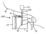
도1은 러더 트렁크에 배치된 러더 스톡을 가진 선박 후미 지역에 설치된 러더를 나타낸 도면이다.
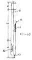
도2는 러더 스톡을 나타낸 도면이다.
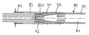
도3은 지지몸체를 가진 러더 스톡의 하단부 지역의 단면도 이다.
도4는 와인딩 맨드럴을 가진 제1지지몸체 지역의 단면도 이다.1 is a view showing a rudder installed in a ship rear region with a rudder stock disposed in the rudder trunk.
2 is a diagram illustrating a rudder stock.
3 is a cross-sectional view of the lower end region of the rudder stock with the support body.
4 is a cross sectional view of a first support body region with a winding mandrel;
도1은 본 발명에 따르는 러더 스톡(40)과, 러더 블레이드(30) 및 러더 트렁크(20)를 가진 러더(100)를 나타낸다. 외팔보로서 설계된 러더 트렁크(20)는 선체(10)와 상단부(20b)로 영구 연결된다. 하부 러더 트렁크 단부(20a)는 러더 블레이드(30) 내에 깊숙히 삽입된다. 러더 트렁크(20)는 중공 러더 트렁크 관으로 설계된다. 내부에서, 러더 트렁크의 상단부 지역은 선체(10)에 설치된 조향기어(11)와 연결된 본 발명에 따르는 러더 스톡(40)과 함께 배치된다. 러더 스톡(40)은 러더 블레이드(30) 내로 삽입된 전체 러더 트렁크(20)를 통하여 공급되고 그리고 러더 트렁크 단부(20a) 위로 돌출한다. 러더 스톡(40)의 하단부 지역(42)은 러더 블레이드(30)에 전체적으로 배치된다.1 shows a
러더(100)는 휜 스티어링(fin steering)(32)으로 조향되는 휜(31)을 가진 스페이드 러더(spade rudder)로 설계되고 그리고 선체(10)의 이동방향으로 선박 프로펠러(12)의 뒤에 배치된다. 그러나, 일반적으로 반(semi)-스페이드 러더(러더 호른을 가짐)로 설계된 러더에 또는 임의적인 러더에 본 발명에 따르는 러더 스톡(40)을 용이하게 사용할 수도 있다. 상기 러더는 피봇 저널 베어링에 의해 단일 부품으로 장착된다.The
도2는 러더 스톡(40)을 나타낸다. 상기 러더 스톡(40)은 3개 지역으로 즉, 러더 스톡의 상단부 지역(41)과, 러더 스톡의 중간 지역(45), 및 러더 스톡의 하단부 지역(42)으로 재분할된다. 러더 스톡의 상부와 하부 단부 지역(41, 42)은 각각 러더 스톡의 중간 지역(45)과 바로 인접한다. 선체(10)의 조향기어(11)에 연결되는 상단부 지역(41)은 단조강으로 제조된다. "단조강"은 탄소 함량이 0.8% 미만인 철(iron)을 의미한다. 대조적으로, 러더 스톡의 하단부 지역(42)과 러더 스톡의 중간 지역(45)은 섬유-복합재료, 특정하게는 탄소섬유로 제조된다. 특히, 러더 스톡의 중간 지역(45)과 하단부 지역(42)은 섬유-복합재료로 제조된 대부분 연속된 트렁크 관으로 만들어진다. 러더 스톡의 중간 지역(45)과 하단부 지역(42)의 섬유-복합재료의 감김(windings)은 도면 번호 '60'으로 표시하였다. 러더 스톡(40)에 대해 소직경을 가진 핀-형상 힘 전달/장착 요소(force transmitting/mounting element)(43)는 러더 스톡(40)의 축선방향으로 하단부 지역(42)으로부터 돌출한다. 단조강으로 제조된 상단부 지역(41)은 도면번호 '51'로 표시되며 러더 스톡의 중간 지역(45)을 향해 러더 스톡(40)의 축선방향으로 돌출한 핀을 갖고, 그 둘레에 상단부 지역(41)과 대면하는 러더 스톡의 중간 지역(45)의 구간이 감겨질 수 있다. 또한, 일반적으로 아교접착과 같은 다른 연결수단을 활용할 수 있다.2 shows a
도3은 러더 스톡의 하단부 지역(42)의 길이방향의 단면을 나타낸다. 상기 하단부 지역(42)은 섬유-복합재료로 제조된 섬유-복합재 관(46)을 포함한다. 섬유-복합재 관(46)은 (주로) 러더 스톡(40)을 형성하며, 지지몸체(70)가 하단부 지역(42)에서 섬유-복합재 관(46)의 내측에 제공된다. 지지몸체(70)는 2개 부분으로 설계되며, 제1지지몸체 부분(71)과 제2지지몸체 부분(72)을 포함한다. 상기 제1지지몸체 부분(71)은 섬유-복합재 관(46)의 자유 단부(461)에 배치된다. 상기 부분(71)은 섬유-복합재 관(46)의 단부(461)에 배치된 베이스 몸체(711)를 포함한다. 상기 베이스 몸체(711)의 외측에서 원주둘레에 배치된 섬유-복합재 관(46)에 위치한 웨브(712)는, 베이스 몸체로부터 섬유-복합재 관(46) 내로 돌출한다. 전체 제1지지몸체 부분(71)은 섬유-복합재 관(46)의 내측에 전체적으로 위치한다. 상기 돌출 웨브(protruding web)는 웨브 사이의 중공 공간이 베이스 몸체(711)로부터 원추형태로 이격 팽창하게 단부쪽으로 경사진다. 제1지지몸체 부분(71)의 외부 지역 또는 각각의 외부 면은, 파도형상 또는 각각의 윤곽으로 나타내는 방식으로 설계된다. 러더 스톡(40)보다 작은 횡단면을 가진 대부분 원통형의 힘 전달/장착 요소(43)는, 러더 스톡(40)으로부터 멀어지는 방향으로 베이스 몸체(711)로부터 돌출한다. 힘 전달/장착 요소(43)의 표면에는 나사부(431)가 제공된다. 유압 너트(33)가 힘 전달/장착 요소(43)의 나사부(431)와 나사 결합한다. 한 편에선, 상기 유압 너트(33)가 러더 블레이드(30)에 러더 스톡(40)을 고정하도록 설계되고, 다른 한 편에선, 유압 너트(33)는 러더 블레이드 연결에서 러더 블레이드(30)와 러더 스톡 과의 사이에 억지 끼워맞춤 조립(interference fit assembly)을 생성한다. 이러한 러더 블레이드 연결 지역(301)에서, 러더 블레이드(30)는 억지 끼워맞춤 조립에 의해서 하단부 지역(42)에서 러더 스톡(40)을 에워싸는 스테인레스강으로 제조된 보호 라이너(47)에 또는 러더 스톡(40)에 인접한다. 보호 라이너(47)는 섬유-복합재 관(46)의 외부 케이싱에 위치하고 그리고 러더 트렁크(20)의 하부 러더 트렁크 단부(20a)까지 섬유-복합재 관(46)의 자유 단부(461)로부터 전체 러더 블레이드 연결 지역(301)의 위로 신장 된다. 베어링(넥 베어링)(21)은 러더 트렁크(20) 내의 러더 스톡(40)의 장착용으로 보호 라이너(47)와 러더 트렁크(20) 사이에 제공된다. 러더 블레이드 연결 지역(301)에서, 러더 스톡(40)은 자유 단부(461) 쪽으로 원추형으로 경사지게 설계된다.3 shows a longitudinal cross section of the
제1지지몸체 부분(71)과 유사하게, 제2지지몸체 부분(72)도 섬유-복합재 관(46)의 내측을 향하여 전체 외부 면이 위치하고 그리고 주된 질량의 베이스 몸체(721)를 갖는다. 베이스 몸체(721)의 외측에 배치된 원주부의 웨브(722)는 섬유-복합재 관(46)의 자유 단부(461)의 방향으로 상기 베이스 몸체(721)로부터 돌출한다. 웨브(712, 722)의 단부 지역에서, 제1 및 제2지지몸체 부분(71, 72)은 웨브(712, 722)의 인접한 쐐기-형태 단부 지역의 억지 끼워맞춤 조립으로 연결된다. 웨브(712, 722)와 베이스 몸체(711, 721)에 의해 경계되는 중공 공간(73)을 포함하는 지지몸체(70)는, 상기 웨브 지역에서 2개의 지지몸체 부분(71, 72)를 연결하여서 형성된다. 양측 베이스 몸체(711, 721)와 힘 전달/장착 요소(43)는 나사 로드(rod) 또는 그와 같은 종류의 것을 공급 통과시키기 위한 대략 중앙에 설정된 관통 구멍(bore hole)(7111, 7121)을 갖는다. 중공 공간을 통해서, 러더 블레이드 연결 지역(301)과 넥 베어링(21) 사이의 최대 하중 지역에서의 지지몸체(70)는, 중공 공간(73) 안으로 탄력적으로 변형되어, 임의 형태의 스프링 효과를 발생한다.Similar to the first
도4는 도3의 제1지지몸체 부분(71)을 나타낸다. 웨브(712)의 내측을 향하여 원주둘레에 그 전체 면이 위치한 와인딩 맨드럴(80)의 단부 지역이 웨브(712) 내측과 결합한다. 상기 와인딩 맨드럴(80)은 원통형 롤러(81)를 포함한다. 상기 원통형 롤러에는, 제1지지몸체 부분(71)의 치수에 맞게 또는 감겨지는 러더 스톡(40)의 치수에 맞게 개조된 맨드럴 어댑터(82)가 배치된다. 지지몸체 부분(71)의 힘 전달/장착 요소(43)는 유지 공구(83)의 플랜지(831)에 의해 유지된다. 또한, 상기 유지 공구(83)는 네일 칼라(nail collar)(832)를 갖는다. 롤러 또는 스풀에 감겨진 섬유 재료(여기서는 도시 않음)가 상기 네일 칼라 둘레에 부착된다. 상기 네일 칼라(832)에 의해 유지된 감김 재료(wound material)는 제1지지몸체 부분(71)의 윤곽진 외부 지역의 둘레에 감겨지고, 그리고 부가로 와인딩 맨드럴(80) 둘레에 감겨져 섬유-복합재 관(46)을 형성한다. 섬유-복합재 관(46)을 완성한 후에, 감김 코어(80)와 가능하다면 유지 공구(83)는 제1지지몸체 부분(71)의 홀더(holder)로부터 제거된다. 또한, 이제는 제2지지몸체 부분(72)이 배치된 섬유-복합재 관(46)의 단부를 통해 삽입될 수 있고, 제1지지몸체 부분(71)에서 제거되고 그리고 제1지지몸체 부분(71)까지 이동될 수 있다. 2개의 지지몸체 부분(71, 72)을 함께 연결하자마자, 억지 끼워맞춤 조립이 지지몸체(70)가 수립되게 양측 부분 사이에서 수립된다. 상기 억지 끼워맞춤 조립은 예를 들어 섬유-복합재 관(46) 안에 삽입하기 전에 제2지지몸체 부분(72)을 냉각하고(icing), 이어서 관(46)에서 가열하여(heating) 실시할 수 있다.
4 shows a first
100: 러더
10: 선체 11: 조향기어 12: 선박 프로펠러
20: 러더 트렁크 20a: 하부 러더 트렁크 단부
20b: 상부 러더 트렁크 단부 21: 넥 베어링
30: 러더 블레이드 31: 휜 32: 휜 스티어링 33: 유압 너트
301: 러더 블레이드 연결 지역
40: 러더 스톡 41: 상단부 지역 42: 하단부 지역
43: 힘 전달/장착 요소 45: 러더 스톡의 중간 지역 46: 섬유-복합재 관
47: 보호 라이너(liner) 431: 나사부 461: 자유 단부
51: 핀
60: 섬유-복합재 재료의 감김부(windings)
70: 지지몸체 71: 제1지지몸체 부분 72: 제2지지몸체 부분
73: 중공 공간 711: 베이스 몸체 712: 웨브 721: 베이스 몸체
722: 웨브 7111: 관통 구멍 7121: 관통 구멍
80: 와인딩 맨드럴 81: 롤러 82: 맨드럴 어댑터 83: 유지 공구
831: 플랜지 832: 네일 칼라 100: Rudder
10: hull 11: steering gear 12: ship propeller
20:
20b: upper rudder trunk end 21: neck bearing
30: rudder blade 31: 휜 32: 휜 steering 33: hydraulic nut
301: rudder blade connection area
40: Rudder Stock 41: Upper Area 42: Lower Area
43: force transmission / mounting element 45: intermediate area of rudder stock 46: fiber-composite tube
47: protective liner 431: threaded portion 461: free end
51: pin
60: windings of the fiber-composite material
70: support body 71: first support body portion 72: second support body portion
73: hollow space 711: base body 712: web 721: base body
722: web 7111: through hole 7121: through hole
80: winding mandrel 81: roller 82: mandrel adapter 83: holding tool
831: flange 832: nail collar
Claims (22)
9. The support body according to claim 8, wherein the support body (70) is designed in two parts; Preferably at least one of the two support body parts 71, 72, particularly preferably both parts, have a circumferential portion, in particular a ring-shaped web 712; 722, projecting from the support body parts 71; 72. A rudder stock, characterized in that the support body portion can be connected to other support body portions by forming a hollow space (73) by in particular an interference fit assembly.
a)특히 금속으로 제조된 지지몸체(70)를 제공하는 단계와,
b)와인딩 맨드럴(80)을 제공하는 단계와,
c)상기 지지몸체(70)의 옆에 와인딩 맨드럴(80)을 배열하는 단계와,
d)상기 지지몸체(70)의 둘레와 와인딩 맨드럴(80)의 둘레에 섬유재료를 감아서 섬유-복합재 관(46)을 생성하는 단계와,
e)적용 가능한 경우에, 와인딩 맨드럴(80)을 제거하는 단계, 및
f)적용 가능한 경우에, 특히 금속 재료로 제조된 상단부 지역(41)을 고정하며, 지지몸체(70)로부터 멀리 향하는 섬유-복합재 관(46)의 단부에서 조향기어(11)와 결합하는 단계를 포함하는 것을 특징으로 하는 방법.A method of producing a rudder stock 40 of a marine rudder 100, the method comprising:
a) providing a support body 70, in particular made of metal,
b) providing a winding mandrel 80,
c) arranging a winding mandrel 80 next to the support body 70;
d) winding the fiber material around the support body 70 and around the winding mandrel 80 to produce a fiber-composite tube 46;
e) if applicable, removing the winding mandrel 80, and
f) where applicable, fixing the top region 41, in particular made of metal material, and engaging the steering gear 11 at the end of the fiber-composite tube 46 facing away from the support body 70. Method comprising a.
a)특히 금속으로 제조된 지지몸체(70)의 제공,
b)와인딩 맨드럴(80)의 제공,
c)상기 지지몸체(70)의 옆에 와인딩 맨드럴(80)의 배열,
d)상기 지지몸체(70)의 둘레와 와인딩 맨드럴(80)의 둘레에 섬유재료를 감아서 섬유-복합재 관(46)을 생성,
e)적용 가능한 경우에, 와인딩 맨드럴(80)의 제거, 및
f)적용 가능한 경우에, 특히 금속재료로 제조된 상단부 지역(41)을 고정하며, 지지몸체(70)로부터 멀리 향하는 섬유-복합재 관(46)의 단부에서 조향기어(11)와 결합하여 얻을 수 있는 선박용 러더의 러더 스톡.Rudder stock of ship rudder:
a) provision of a support body 70, in particular made of metal,
b) the provision of the winding mandrel 80,
c) the arrangement of the winding mandrel 80 next to the support body 70,
d) winding the fiber material around the support body 70 and around the winding mandrel 80 to produce a fiber-composite tube 46,
e) if applicable, removal of the winding mandrel 80, and
f) Where applicable, it may be obtained in combination with the steering gear 11 at the end of the fiber-composite tube 46 facing away from the support body 70, in particular fixing the top region 41 made of metallic material. Rudder stock of a ship rudder.
Applications Claiming Priority (4)
| Application Number | Priority Date | Filing Date | Title |
|---|---|---|---|
| DE102009015234 | 2009-04-01 | ||
| DE102009015234.2 | 2009-04-01 | ||
| DE102009022989.2 | 2009-05-28 | ||
| DE102009022989A DE102009022989A1 (en) | 2009-04-01 | 2009-05-28 | rudder |
Publications (2)
| Publication Number | Publication Date |
|---|---|
| KR20100109877A true KR20100109877A (en) | 2010-10-11 |
| KR101625686B1 KR101625686B1 (en) | 2016-05-30 |
Family
ID=42338250
Family Applications (1)
| Application Number | Title | Priority Date | Filing Date |
|---|---|---|---|
| KR1020100029922A KR101625686B1 (en) | 2009-04-01 | 2010-04-01 | Rudder stock |
Country Status (13)
| Country | Link |
|---|---|
| US (1) | US8720358B2 (en) |
| EP (1) | EP2236410B1 (en) |
| JP (1) | JP5472856B2 (en) |
| KR (1) | KR101625686B1 (en) |
| CN (1) | CN101857083B (en) |
| DE (1) | DE102009022989A1 (en) |
| DK (1) | DK2236410T3 (en) |
| ES (1) | ES2461151T3 (en) |
| HR (1) | HRP20140393T1 (en) |
| PL (1) | PL2236410T3 (en) |
| PT (1) | PT2236410E (en) |
| SG (1) | SG165298A1 (en) |
| SI (1) | SI2236410T1 (en) |
Cited By (2)
| Publication number | Priority date | Publication date | Assignee | Title |
|---|---|---|---|---|
| KR101246895B1 (en) * | 2010-11-12 | 2013-04-01 | 삼성중공업 주식회사 | Power transmitting apparatus of ship and ship using the same |
| KR101504949B1 (en) * | 2011-08-17 | 2015-03-23 | 티센크루프 마린 시스템즈 게엠베하 | A rudder device for a water vehicle |
Families Citing this family (10)
| Publication number | Priority date | Publication date | Assignee | Title |
|---|---|---|---|---|
| ES2824762T3 (en) * | 2011-10-17 | 2021-05-13 | Becker Marine Systems Gmbh | Device for maneuvering a vessel and procedure for manufacturing a maneuvering device for vessels |
| CN102991661B (en) * | 2012-09-30 | 2015-08-19 | 浙江联洋复合材料有限公司 | Carbon fiber rudder stock and manufacture method thereof |
| US8584610B1 (en) | 2013-03-07 | 2013-11-19 | Corning Townsend | Spring loaded geared flap rudder |
| NO336848B1 (en) * | 2013-03-08 | 2015-11-16 | Rolls Royce Marine As Rudders | rudder device |
| CN107021198A (en) * | 2017-06-09 | 2017-08-08 | 浙江舟山博斯特船舶设计研究院有限公司 | A kind of rudder system device for ship |
| CN107554742A (en) * | 2017-09-15 | 2018-01-09 | 南通如港船舶配套机械有限公司 | A kind of ship rudder lever |
| US10935068B2 (en) * | 2017-11-16 | 2021-03-02 | Goodrich Corporation | Designs and methods of making of joints for composite components under dominant bending load |
| DE102019001585A1 (en) * | 2019-03-08 | 2020-09-10 | Ralph Funck | Fiber composite strut |
| AU2020437827A1 (en) * | 2019-12-23 | 2022-07-21 | Michigan Wheel | Marine wake adapted rudder assembly |
| CN111661303B (en) * | 2020-06-17 | 2022-01-11 | 东台市海鹏船舶配件厂 | Marine rudder bearing and rudder stock structure with separated clamping |
Family Cites Families (16)
| Publication number | Priority date | Publication date | Assignee | Title |
|---|---|---|---|---|
| US3919962A (en) * | 1971-09-13 | 1975-11-18 | Turnbull Marine Design | Rudder arrangements for ships |
| DE8222839U1 (en) | 1982-08-13 | 1983-05-05 | Arendts, Franz Joseph, Prof., 8000 München | Connection connection for driving or driven hollow shafts made of fiber composite material |
| DE3742255C1 (en) * | 1987-12-12 | 1989-05-18 | Uni Cardan Ag | Method of making waves |
| US5215413A (en) * | 1991-07-26 | 1993-06-01 | Westinghouse Electric Corp. | Composite-to-metal shaft joint |
| FR2693701B1 (en) * | 1992-07-16 | 1994-09-02 | France Etat Armement | Safran for medium and large tonnage ships. |
| US5456200A (en) * | 1993-10-13 | 1995-10-10 | The United States Of America As Represented By The Secretary Of The Navy | Rudder for reduced cavitation |
| US5415122A (en) * | 1993-10-13 | 1995-05-16 | The United States Of America As Represented By The Secretary Of The Navy | Twisted rudder for a vessel |
| DE19524903A1 (en) * | 1995-07-08 | 1997-04-30 | Inst Kraftfahrwesen Rwth Aache | Force transmission device for use in vehicle construction |
| US6227131B1 (en) * | 1997-05-19 | 2001-05-08 | Tides Marine, Inc. | Sailboat rudder having a monocoque structure |
| US6464591B1 (en) * | 1998-06-26 | 2002-10-15 | Ntn Corporation | Power transmission shaft |
| JP3296328B2 (en) | 1999-05-11 | 2002-06-24 | 株式会社豊田自動織機 | Fiber reinforced plastic pipe |
| DE10205657C2 (en) * | 2001-04-03 | 2003-12-24 | Eurocopter Deutschland | Process for producing a tubular, torsionally and flexurally rigid drive shaft |
| DE202005013583U1 (en) | 2005-06-30 | 2005-11-03 | Becker Marine Systems Gmbh & Co. Kg | Rudder stock for water craft, has end sections made of wrought iron, and middle stock section connected with end sections and made of carbon fibrous composite or graphite fibers, which form middle stock section in the form of windings |
| KR200410384Y1 (en) * | 2005-12-21 | 2006-03-08 | 삼성중공업 주식회사 | The spade rudder |
| DE202007012480U1 (en) * | 2007-09-05 | 2007-11-29 | Becker Marine Systems Gmbh & Co. Kg | Oars for ships |
| DE102007044698B4 (en) * | 2007-09-19 | 2010-04-15 | Blohm + Voss Industries Gmbh | Method for producing wing elements |
-
2009
- 2009-05-28 DE DE102009022989A patent/DE102009022989A1/en not_active Ceased
-
2010
- 2010-03-25 SI SI201030595T patent/SI2236410T1/en unknown
- 2010-03-25 DK DK10157753.4T patent/DK2236410T3/en active
- 2010-03-25 PL PL10157753T patent/PL2236410T3/en unknown
- 2010-03-25 PT PT101577534T patent/PT2236410E/en unknown
- 2010-03-25 ES ES10157753.4T patent/ES2461151T3/en active Active
- 2010-03-25 EP EP10157753.4A patent/EP2236410B1/en active Active
- 2010-03-29 SG SG201002219-2A patent/SG165298A1/en unknown
- 2010-03-30 JP JP2010078926A patent/JP5472856B2/en not_active Expired - Fee Related
- 2010-04-01 KR KR1020100029922A patent/KR101625686B1/en active IP Right Grant
- 2010-04-01 CN CN201010141580.8A patent/CN101857083B/en active Active
- 2010-04-01 US US12/752,498 patent/US8720358B2/en not_active Expired - Fee Related
-
2014
- 2014-04-30 HR HRP20140393AT patent/HRP20140393T1/en unknown
Cited By (2)
| Publication number | Priority date | Publication date | Assignee | Title |
|---|---|---|---|---|
| KR101246895B1 (en) * | 2010-11-12 | 2013-04-01 | 삼성중공업 주식회사 | Power transmitting apparatus of ship and ship using the same |
| KR101504949B1 (en) * | 2011-08-17 | 2015-03-23 | 티센크루프 마린 시스템즈 게엠베하 | A rudder device for a water vehicle |
Also Published As
| Publication number | Publication date |
|---|---|
| DK2236410T3 (en) | 2014-05-12 |
| JP2010241420A (en) | 2010-10-28 |
| US8720358B2 (en) | 2014-05-13 |
| PL2236410T3 (en) | 2014-07-31 |
| SI2236410T1 (en) | 2014-08-29 |
| US20100251951A1 (en) | 2010-10-07 |
| DE102009022989A1 (en) | 2010-10-14 |
| EP2236410A3 (en) | 2012-03-14 |
| SG165298A1 (en) | 2010-10-28 |
| EP2236410B1 (en) | 2014-03-05 |
| CN101857083A (en) | 2010-10-13 |
| JP5472856B2 (en) | 2014-04-16 |
| CN101857083B (en) | 2014-11-12 |
| EP2236410A2 (en) | 2010-10-06 |
| KR101625686B1 (en) | 2016-05-30 |
| HRP20140393T1 (en) | 2014-06-06 |
| ES2461151T3 (en) | 2014-05-16 |
| PT2236410E (en) | 2014-05-07 |
Similar Documents
| Publication | Publication Date | Title |
|---|---|---|
| KR20100109877A (en) | Rudder stock | |
| JP2010241420A6 (en) | Rudder stock | |
| CN101380996B (en) | Rudder for ships | |
| US4256412A (en) | Rod-shaped connecting element | |
| CN101151458B (en) | Blade for wind-power generators | |
| EP1739008B1 (en) | Rudder shaft for a watercraft rudder | |
| CN101668650A (en) | Stress reducing inner sleeve for twist beam and associated method | |
| US8388001B2 (en) | Transverse control arm | |
| CN101316754A (en) | Hollow shaft connection piece | |
| US11230154B2 (en) | Connection system for connecting a damping unit of a motor vehicle inside a wheel suspension of said vehicle | |
| CA2632002A1 (en) | Web-winding core | |
| CN108799315B (en) | Composite material transmission shaft for vehicle and preparation method thereof | |
| KR101504949B1 (en) | A rudder device for a water vehicle | |
| CN103661632A (en) | Instrument panel beam of motor vehicle formed by two pipes and strut made of composite material | |
| KR102168942B1 (en) | Propulsion System of Ship | |
| JP2017534793A (en) | Wind turbine rotor blade | |
| US10703454B2 (en) | Modular propulsion unit nozzle | |
| JP2019094953A (en) | Cylindrical structure | |
| EP0703144B1 (en) | Method for manufacturing a bearing structure for a spacecraft, and bearing structure | |
| US2712462A (en) | Jointed connecting piece, especially for motor vehicle steering gears | |
| CN102338247A (en) | Connecting and supporting combined device for inner oil pipe in adjustable propeller | |
| GB2452357A (en) | Screw connection | |
| US20220402322A1 (en) | Vehicle rigid axle and method of manufacturing same | |
| US20220025922A1 (en) | Production assembly and method for hybrid composite driveshaft tube | |
| CN112722181A (en) | Rivet pin type connecting device capable of being quickly assembled and disassembled and dynamically adjusting load of large floating body connection |
Legal Events
| Date | Code | Title | Description |
|---|---|---|---|
| A201 | Request for examination | ||
| A302 | Request for accelerated examination | ||
| E902 | Notification of reason for refusal | ||
| E701 | Decision to grant or registration of patent right | ||
| GRNT | Written decision to grant |