KR20100102040A - Enclosed battery and method of manufacturing thereof - Google Patents
Enclosed battery and method of manufacturing thereof Download PDFInfo
- Publication number
- KR20100102040A KR20100102040A KR1020100012739A KR20100012739A KR20100102040A KR 20100102040 A KR20100102040 A KR 20100102040A KR 1020100012739 A KR1020100012739 A KR 1020100012739A KR 20100012739 A KR20100012739 A KR 20100012739A KR 20100102040 A KR20100102040 A KR 20100102040A
- Authority
- KR
- South Korea
- Prior art keywords
- hole
- plate
- terminal
- sealed
- diameter portion
- Prior art date
Links
Images


Classifications
-
- H—ELECTRICITY
- H01—ELECTRIC ELEMENTS
- H01M—PROCESSES OR MEANS, e.g. BATTERIES, FOR THE DIRECT CONVERSION OF CHEMICAL ENERGY INTO ELECTRICAL ENERGY
- H01M50/00—Constructional details or processes of manufacture of the non-active parts of electrochemical cells other than fuel cells, e.g. hybrid cells
- H01M50/50—Current conducting connections for cells or batteries
- H01M50/543—Terminals
-
- H—ELECTRICITY
- H01—ELECTRIC ELEMENTS
- H01M—PROCESSES OR MEANS, e.g. BATTERIES, FOR THE DIRECT CONVERSION OF CHEMICAL ENERGY INTO ELECTRICAL ENERGY
- H01M10/00—Secondary cells; Manufacture thereof
- H01M10/42—Methods or arrangements for servicing or maintenance of secondary cells or secondary half-cells
-
- H—ELECTRICITY
- H01—ELECTRIC ELEMENTS
- H01M—PROCESSES OR MEANS, e.g. BATTERIES, FOR THE DIRECT CONVERSION OF CHEMICAL ENERGY INTO ELECTRICAL ENERGY
- H01M10/00—Secondary cells; Manufacture thereof
- H01M10/05—Accumulators with non-aqueous electrolyte
-
- H—ELECTRICITY
- H01—ELECTRIC ELEMENTS
- H01M—PROCESSES OR MEANS, e.g. BATTERIES, FOR THE DIRECT CONVERSION OF CHEMICAL ENERGY INTO ELECTRICAL ENERGY
- H01M10/00—Secondary cells; Manufacture thereof
- H01M10/05—Accumulators with non-aqueous electrolyte
- H01M10/058—Construction or manufacture
-
- H—ELECTRICITY
- H01—ELECTRIC ELEMENTS
- H01M—PROCESSES OR MEANS, e.g. BATTERIES, FOR THE DIRECT CONVERSION OF CHEMICAL ENERGY INTO ELECTRICAL ENERGY
- H01M10/00—Secondary cells; Manufacture thereof
- H01M10/06—Lead-acid accumulators
- H01M10/12—Construction or manufacture
-
- H—ELECTRICITY
- H01—ELECTRIC ELEMENTS
- H01M—PROCESSES OR MEANS, e.g. BATTERIES, FOR THE DIRECT CONVERSION OF CHEMICAL ENERGY INTO ELECTRICAL ENERGY
- H01M10/00—Secondary cells; Manufacture thereof
- H01M10/34—Gastight accumulators
- H01M10/345—Gastight metal hydride accumulators
-
- H—ELECTRICITY
- H01—ELECTRIC ELEMENTS
- H01M—PROCESSES OR MEANS, e.g. BATTERIES, FOR THE DIRECT CONVERSION OF CHEMICAL ENERGY INTO ELECTRICAL ENERGY
- H01M10/00—Secondary cells; Manufacture thereof
- H01M10/42—Methods or arrangements for servicing or maintenance of secondary cells or secondary half-cells
- H01M10/425—Structural combination with electronic components, e.g. electronic circuits integrated to the outside of the casing
-
- H—ELECTRICITY
- H01—ELECTRIC ELEMENTS
- H01M—PROCESSES OR MEANS, e.g. BATTERIES, FOR THE DIRECT CONVERSION OF CHEMICAL ENERGY INTO ELECTRICAL ENERGY
- H01M10/00—Secondary cells; Manufacture thereof
- H01M10/42—Methods or arrangements for servicing or maintenance of secondary cells or secondary half-cells
- H01M10/48—Accumulators combined with arrangements for measuring, testing or indicating the condition of cells, e.g. the level or density of the electrolyte
-
- H—ELECTRICITY
- H01—ELECTRIC ELEMENTS
- H01M—PROCESSES OR MEANS, e.g. BATTERIES, FOR THE DIRECT CONVERSION OF CHEMICAL ENERGY INTO ELECTRICAL ENERGY
- H01M50/00—Constructional details or processes of manufacture of the non-active parts of electrochemical cells other than fuel cells, e.g. hybrid cells
- H01M50/10—Primary casings, jackets or wrappings of a single cell or a single battery
- H01M50/102—Primary casings, jackets or wrappings of a single cell or a single battery characterised by their shape or physical structure
- H01M50/103—Primary casings, jackets or wrappings of a single cell or a single battery characterised by their shape or physical structure prismatic or rectangular
-
- H—ELECTRICITY
- H01—ELECTRIC ELEMENTS
- H01M—PROCESSES OR MEANS, e.g. BATTERIES, FOR THE DIRECT CONVERSION OF CHEMICAL ENERGY INTO ELECTRICAL ENERGY
- H01M50/00—Constructional details or processes of manufacture of the non-active parts of electrochemical cells other than fuel cells, e.g. hybrid cells
- H01M50/10—Primary casings, jackets or wrappings of a single cell or a single battery
- H01M50/172—Arrangements of electric connectors penetrating the casing
- H01M50/174—Arrangements of electric connectors penetrating the casing adapted for the shape of the cells
- H01M50/176—Arrangements of electric connectors penetrating the casing adapted for the shape of the cells for prismatic or rectangular cells
-
- H—ELECTRICITY
- H01—ELECTRIC ELEMENTS
- H01M—PROCESSES OR MEANS, e.g. BATTERIES, FOR THE DIRECT CONVERSION OF CHEMICAL ENERGY INTO ELECTRICAL ENERGY
- H01M50/00—Constructional details or processes of manufacture of the non-active parts of electrochemical cells other than fuel cells, e.g. hybrid cells
- H01M50/10—Primary casings, jackets or wrappings of a single cell or a single battery
- H01M50/183—Sealing members
- H01M50/184—Sealing members characterised by their shape or structure
-
- H—ELECTRICITY
- H01—ELECTRIC ELEMENTS
- H01M—PROCESSES OR MEANS, e.g. BATTERIES, FOR THE DIRECT CONVERSION OF CHEMICAL ENERGY INTO ELECTRICAL ENERGY
- H01M50/00—Constructional details or processes of manufacture of the non-active parts of electrochemical cells other than fuel cells, e.g. hybrid cells
- H01M50/10—Primary casings, jackets or wrappings of a single cell or a single battery
- H01M50/183—Sealing members
- H01M50/186—Sealing members characterised by the disposition of the sealing members
-
- H—ELECTRICITY
- H01—ELECTRIC ELEMENTS
- H01M—PROCESSES OR MEANS, e.g. BATTERIES, FOR THE DIRECT CONVERSION OF CHEMICAL ENERGY INTO ELECTRICAL ENERGY
- H01M50/00—Constructional details or processes of manufacture of the non-active parts of electrochemical cells other than fuel cells, e.g. hybrid cells
- H01M50/10—Primary casings, jackets or wrappings of a single cell or a single battery
- H01M50/183—Sealing members
- H01M50/19—Sealing members characterised by the material
- H01M50/191—Inorganic material
-
- H—ELECTRICITY
- H01—ELECTRIC ELEMENTS
- H01M—PROCESSES OR MEANS, e.g. BATTERIES, FOR THE DIRECT CONVERSION OF CHEMICAL ENERGY INTO ELECTRICAL ENERGY
- H01M50/00—Constructional details or processes of manufacture of the non-active parts of electrochemical cells other than fuel cells, e.g. hybrid cells
- H01M50/10—Primary casings, jackets or wrappings of a single cell or a single battery
- H01M50/183—Sealing members
- H01M50/19—Sealing members characterised by the material
- H01M50/197—Sealing members characterised by the material having a layered structure
-
- H—ELECTRICITY
- H01—ELECTRIC ELEMENTS
- H01M—PROCESSES OR MEANS, e.g. BATTERIES, FOR THE DIRECT CONVERSION OF CHEMICAL ENERGY INTO ELECTRICAL ENERGY
- H01M50/00—Constructional details or processes of manufacture of the non-active parts of electrochemical cells other than fuel cells, e.g. hybrid cells
- H01M50/10—Primary casings, jackets or wrappings of a single cell or a single battery
- H01M50/183—Sealing members
- H01M50/19—Sealing members characterised by the material
- H01M50/198—Sealing members characterised by the material characterised by physical properties, e.g. adhesiveness or hardness
-
- H—ELECTRICITY
- H01—ELECTRIC ELEMENTS
- H01M—PROCESSES OR MEANS, e.g. BATTERIES, FOR THE DIRECT CONVERSION OF CHEMICAL ENERGY INTO ELECTRICAL ENERGY
- H01M50/00—Constructional details or processes of manufacture of the non-active parts of electrochemical cells other than fuel cells, e.g. hybrid cells
- H01M50/20—Mountings; Secondary casings or frames; Racks, modules or packs; Suspension devices; Shock absorbers; Transport or carrying devices; Holders
-
- H—ELECTRICITY
- H01—ELECTRIC ELEMENTS
- H01M—PROCESSES OR MEANS, e.g. BATTERIES, FOR THE DIRECT CONVERSION OF CHEMICAL ENERGY INTO ELECTRICAL ENERGY
- H01M50/00—Constructional details or processes of manufacture of the non-active parts of electrochemical cells other than fuel cells, e.g. hybrid cells
- H01M50/50—Current conducting connections for cells or batteries
- H01M50/543—Terminals
- H01M50/547—Terminals characterised by the disposition of the terminals on the cells
- H01M50/55—Terminals characterised by the disposition of the terminals on the cells on the same side of the cell
-
- H—ELECTRICITY
- H01—ELECTRIC ELEMENTS
- H01M—PROCESSES OR MEANS, e.g. BATTERIES, FOR THE DIRECT CONVERSION OF CHEMICAL ENERGY INTO ELECTRICAL ENERGY
- H01M50/00—Constructional details or processes of manufacture of the non-active parts of electrochemical cells other than fuel cells, e.g. hybrid cells
- H01M50/50—Current conducting connections for cells or batteries
- H01M50/543—Terminals
- H01M50/552—Terminals characterised by their shape
- H01M50/553—Terminals adapted for prismatic, pouch or rectangular cells
-
- H—ELECTRICITY
- H01—ELECTRIC ELEMENTS
- H01M—PROCESSES OR MEANS, e.g. BATTERIES, FOR THE DIRECT CONVERSION OF CHEMICAL ENERGY INTO ELECTRICAL ENERGY
- H01M50/00—Constructional details or processes of manufacture of the non-active parts of electrochemical cells other than fuel cells, e.g. hybrid cells
- H01M50/50—Current conducting connections for cells or batteries
- H01M50/543—Terminals
- H01M50/564—Terminals characterised by their manufacturing process
- H01M50/566—Terminals characterised by their manufacturing process by welding, soldering or brazing
-
- H—ELECTRICITY
- H01—ELECTRIC ELEMENTS
- H01M—PROCESSES OR MEANS, e.g. BATTERIES, FOR THE DIRECT CONVERSION OF CHEMICAL ENERGY INTO ELECTRICAL ENERGY
- H01M50/00—Constructional details or processes of manufacture of the non-active parts of electrochemical cells other than fuel cells, e.g. hybrid cells
- H01M50/50—Current conducting connections for cells or batteries
- H01M50/572—Means for preventing undesired use or discharge
- H01M50/574—Devices or arrangements for the interruption of current
-
- H—ELECTRICITY
- H01—ELECTRIC ELEMENTS
- H01M—PROCESSES OR MEANS, e.g. BATTERIES, FOR THE DIRECT CONVERSION OF CHEMICAL ENERGY INTO ELECTRICAL ENERGY
- H01M50/00—Constructional details or processes of manufacture of the non-active parts of electrochemical cells other than fuel cells, e.g. hybrid cells
- H01M50/60—Arrangements or processes for filling or topping-up with liquids; Arrangements or processes for draining liquids from casings
- H01M50/609—Arrangements or processes for filling with liquid, e.g. electrolytes
- H01M50/627—Filling ports
-
- Y—GENERAL TAGGING OF NEW TECHNOLOGICAL DEVELOPMENTS; GENERAL TAGGING OF CROSS-SECTIONAL TECHNOLOGIES SPANNING OVER SEVERAL SECTIONS OF THE IPC; TECHNICAL SUBJECTS COVERED BY FORMER USPC CROSS-REFERENCE ART COLLECTIONS [XRACs] AND DIGESTS
- Y02—TECHNOLOGIES OR APPLICATIONS FOR MITIGATION OR ADAPTATION AGAINST CLIMATE CHANGE
- Y02E—REDUCTION OF GREENHOUSE GAS [GHG] EMISSIONS, RELATED TO ENERGY GENERATION, TRANSMISSION OR DISTRIBUTION
- Y02E60/00—Enabling technologies; Technologies with a potential or indirect contribution to GHG emissions mitigation
- Y02E60/10—Energy storage using batteries
-
- Y—GENERAL TAGGING OF NEW TECHNOLOGICAL DEVELOPMENTS; GENERAL TAGGING OF CROSS-SECTIONAL TECHNOLOGIES SPANNING OVER SEVERAL SECTIONS OF THE IPC; TECHNICAL SUBJECTS COVERED BY FORMER USPC CROSS-REFERENCE ART COLLECTIONS [XRACs] AND DIGESTS
- Y02—TECHNOLOGIES OR APPLICATIONS FOR MITIGATION OR ADAPTATION AGAINST CLIMATE CHANGE
- Y02P—CLIMATE CHANGE MITIGATION TECHNOLOGIES IN THE PRODUCTION OR PROCESSING OF GOODS
- Y02P70/00—Climate change mitigation technologies in the production process for final industrial or consumer products
- Y02P70/50—Manufacturing or production processes characterised by the final manufactured product
-
- Y—GENERAL TAGGING OF NEW TECHNOLOGICAL DEVELOPMENTS; GENERAL TAGGING OF CROSS-SECTIONAL TECHNOLOGIES SPANNING OVER SEVERAL SECTIONS OF THE IPC; TECHNICAL SUBJECTS COVERED BY FORMER USPC CROSS-REFERENCE ART COLLECTIONS [XRACs] AND DIGESTS
- Y02—TECHNOLOGIES OR APPLICATIONS FOR MITIGATION OR ADAPTATION AGAINST CLIMATE CHANGE
- Y02T—CLIMATE CHANGE MITIGATION TECHNOLOGIES RELATED TO TRANSPORTATION
- Y02T10/00—Road transport of goods or passengers
- Y02T10/60—Other road transportation technologies with climate change mitigation effect
- Y02T10/70—Energy storage systems for electromobility, e.g. batteries
-
- Y—GENERAL TAGGING OF NEW TECHNOLOGICAL DEVELOPMENTS; GENERAL TAGGING OF CROSS-SECTIONAL TECHNOLOGIES SPANNING OVER SEVERAL SECTIONS OF THE IPC; TECHNICAL SUBJECTS COVERED BY FORMER USPC CROSS-REFERENCE ART COLLECTIONS [XRACs] AND DIGESTS
- Y10—TECHNICAL SUBJECTS COVERED BY FORMER USPC
- Y10T—TECHNICAL SUBJECTS COVERED BY FORMER US CLASSIFICATION
- Y10T29/00—Metal working
- Y10T29/49—Method of mechanical manufacture
- Y10T29/49002—Electrical device making
- Y10T29/49108—Electric battery cell making
- Y10T29/4911—Electric battery cell making including sealing
Abstract
Description
본 발명은 비수전해질(非水電解質) 2차전지, 니켈-수소 2차전지 등의 밀폐전지에 관한 것이고, 특히, 내부에 전류차단기구를 구비하고, 제조시에 전해액이나 세정액이 전류차단기구 내에 침입하기 어려운 구성의 접속단자를 구비한 고신뢰성의 밀폐전지 및 그 제조방법에 관한 것이다.BACKGROUND OF THE INVENTION 1. Field of the Invention [0001] The present invention relates to sealed batteries such as nonaqueous electrolyte secondary batteries and nickel-hydrogen secondary batteries. Particularly, the present invention provides a current interruption mechanism therein, and at the time of manufacture, an electrolyte solution and a cleaning solution are contained in the current interruption mechanism. The present invention relates to a highly reliable sealed battery having a connection terminal having a structure which is difficult to invade, and a manufacturing method thereof.
휴대전화기, 휴대형 퍼스널 컴퓨터, 휴대형 음악 플레이어 등의 휴대형 전자기기의 구동전원으로서, 니켈수소전지로 대표되는 알칼리 2차전지나 리튬이온 배터리로 대표되는 비수전해질 2차전지가 많이 사용되고 있다. 또한, 환경보호운동의 고조를 배경으로 하여 이산화탄소 가스 등의 배출규제가 강화되고 있기 때문에, 자동차 업계에서는, 가솔린, 디젤유, 천연가스 등의 화석연료를 사용하는 자동차뿐만이 아니라, 전기자동차(EV)나 하이브리드 전기자동차(HEV)의 개발이 활발하게 행해지고 있다. 이에 더하여, 최근의 화석연료의 가격의 급격한 상승은 이러한 EV나 HEV의 개발을 진행시키는 순풍이 되고 있다.BACKGROUND ART As a driving power source for portable electronic devices such as mobile phones, portable personal computers, portable music players, and the like, alkali secondary batteries represented by nickel hydride batteries and nonaqueous electrolyte secondary batteries represented by lithium ion batteries are widely used. In addition, due to the high environmental protection movement, emission regulations such as carbon dioxide gas are being tightened. In the automobile industry, not only automobiles using fossil fuels such as gasoline, diesel oil and natural gas, but also electric vehicles (EVs) B) Development of hybrid electric vehicles (HEVs) is being actively performed. In addition, the recent sharp rise in the price of fossil fuels has become a favorable wind for the development of such EVs and HEVs.
이와 같은 EV나 HEV 용도에서는 고출력 특성이 요구되므로, 개개의 전지가 대형화되고 있음과 동시에, 다수의 전지를 직렬 내지 병렬로 접속하여 사용되고 있다. 특히, 이와 같은 용도로 사용되는 밀폐전지는, 특히 비수전해질 2차전지에서는 반응성이 매우 높은 재료가 사용되고 있으므로, 소형기기에 이용하는 전지와 비교하여 현격히 높은 안전성이 요구된다. 그 때문에, EV나 HEV 용도에 사용되는 밀폐전지에서는, 하기 특허문헌 1 및 2에 나타내고 있는 바와 같이, 전지 외장(外裝)캔(can) 내의 압력이 높아졌을 때에 내압을 개방하는 가스배출밸브를 설치함과 동시에, 외부단자와 외장캔 내부의 전극체와의 사이의 전기적 접속을 차단하는 전류차단기구를 설치하는 것이 행해지고 있다.In such EV and HEV applications, high output characteristics are required, so that individual batteries are being enlarged and many batteries are connected in series or in parallel. In particular, since a highly reactive material is used for a sealed battery used for such a purpose, especially a nonaqueous electrolyte secondary battery, a significantly higher safety is required than a battery used for a small apparatus. Therefore, in sealed batteries used for EV and HEV applications, as shown in Patent Literatures 1 and 2 below, when the pressure in the battery outer can is increased, a gas discharge valve is released. At the same time, a current interruption mechanism for interrupting electrical connection between the external terminal and the electrode body inside the outer can is provided.
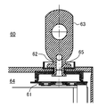
즉, 하기 특허문헌 1에는, 도 6a에 나타낸 바와 같이, 전류차단기구(51)와 밀폐전지(50)의 외측 공간을 연통하는 관통구멍(52)이 형성된 외부단자(53)를 구비하고 있고, 외장캔(54) 내의 압력이 높아졌을 때에 확실히 전류차단기구(51)가 작동하도록 한 밀폐전지(50)의 발명이 개시되어 있다. 또, 하기 특허문헌 2는, 도 6b에 나타낸 바와 같이, 전류차단기구(61)와 밀폐전지(60)의 외측 공간을 연통하는 관통구멍(62)이 형성된 외부단자(63)를 구비하고, 외장캔(64) 내의 압력이 높아졌을 때에 전류차단기구(61)가 작동하게 됨과 동시에, 이 관통구멍(62)으로부터 수분이나 산소가 침입하여 전류차단기구(61)가 열화하는 것을 방지하기 위해서, 관통구멍(62)을 수지제의 막마개(65)에 의해서 봉지(封止)한 밀폐전지의 발명이 개시되어 있다.That is, the following patent document 1 is equipped with the
상기 특허문헌 1 및 2에 개시되어 있는 밀폐전지의 관통구멍은 모두 전류차단기구의 전지 외측에 대응하는 측의 공간과 전지 외부가 통해져 있는 것에 의해, 외장캔 내의 압력이 상승했을 때에 전류차단기구가 작동하기 쉬워지도록 형성되어 있는 것이다. 그 때문에, 상기 인용문헌 2에 개시되어 있는 밀폐전지(60)에서 이용되고 있는 수지제의 막마개(65)는 얇을 필요가 있게 되어 있으며, 강고한 마개로 하는 것은 고려되고 있지 않았다. 그 때문에, 상기 인용문헌 2에 개시되어 있는 밀폐전지(60)에서는 외부로부터 어떠한 충격을 받으면 막마개(65)가 파손해 버릴 가능성이 있고, 게다가 막마개(65)가 파손해 버리면, 상기 인용문헌 1에 나타내고 있는 바와 같이, 외부로부터의 수분이나 산소 등이 침입함으로써 전류차단기구(61)가 열화해 버릴 가능성이 존재하고 있었다.The through-holes of the sealed batteries disclosed in the above Patent Documents 1 and 2 all have a space on the side corresponding to the outside of the battery of the current blocking mechanism and the outside of the battery, so that the current blocking mechanism when the pressure in the outer can rises. Is formed to be easy to operate. For this reason, the
그렇지만, 발명자들의 실험에 의하면, 전류차단기구는 전류차단기구의 전지 외측에 대응하는 측의 공간이 밀폐되어 있어도 개방되어 있어도 동작에 실질적으로 차이가 생기지 않는 것이 발견되었다. 즉, 어떠한 원인에 의해서 외장캔 내의 압력이 증가하여도 이상(異常)시에 전지 내부에서 발생하는 가스압이 매우 크기 때문에, 전류차단기구의 전지 외측에 대응하는 측의 밀폐공간 내의 압력이 동시에 동일하게 증가하는 것은 거의 없어, 전류차단기구의 전지 외측에 대응하는 측의 공간이 밀폐되어 있어도 문제가 되지 않기 때문이다.However, according to the experiments of the inventors, it has been found that the current interruption mechanism does not substantially differ in operation even when the space on the side corresponding to the outside of the battery of the current interruption mechanism is closed or opened. That is, even if the pressure in the outer can increases due to any cause, the gas pressure generated inside the battery at the time of abnormality is very large, so that the pressure in the sealed space on the side corresponding to the outside of the battery of the current interruption mechanism is the same. This is because there is almost no increase, even if the space on the side corresponding to the outside of the battery of the current interruption mechanism is sealed.
본 발명은 상술한 것과 같은 실험결과에 근거하여 이루어진 것으로서, 제조시에 전해액이나 세정액이 전류차단기구 내에 침입하기 어려운 구성의 접속단자를 구비한 고신뢰성의 밀폐전지 및 그 제조방법을 제공하는 것을 목적으로 한다.SUMMARY OF THE INVENTION The present invention has been made on the basis of the experimental results as described above, and an object thereof is to provide a highly reliable sealed battery and a method for manufacturing the same, having a connection terminal having a structure in which electrolyte or a cleaning liquid is less likely to penetrate into a current interruption mechanism during manufacture. It is done.
상기 목적을 달성하기 위해, 본 발명의 밀폐전지는,In order to achieve the above object, the sealed battery of the present invention,
개구(開口)를 가지는 외장캔과,An external can having an opening,
상기 외장캔 내에 수용된 정극집전판(正極集電板) 및 부극집전판(負極集電板)을 각각 구비하는 정극극판(正極極板) 및 부극극판(負極極板)을 가지는 전극체와,An electrode body having a positive electrode plate and a negative electrode plate each having a positive electrode current collector plate and a negative electrode current collector plate housed in the outer can;
상기 외장캔의 개구를 봉구(封口)하고 있는 봉구판과,A sealing plate sealing the opening of the outer can;
상기 봉구판에 장착된 접속단자를 가지는 외부단자를 구비한 밀폐전지로서,A sealed battery having an external terminal having a connection terminal mounted on the sealing plate,
상기 접속단자와 상기 전극체는 전기적으로 접속되고,The connection terminal and the electrode body are electrically connected,
상기 접속단자와 상기 전극체를 전기적으로 접속하는 도전(導電) 경로의 사이에 상기 외장캔 내부의 압력의 상승에 대응하여 전류를 차단하는 전류차단기구가 설치되며,Between the connection terminal and the conductive path for electrically connecting the electrode body, a current interruption mechanism is provided for interrupting the current in response to the increase in the pressure inside the outer can.
상기 접속단자는 그 내부에 상기 전류차단기구의 전지 외측에 대응하는 측의 공간과 이어지는 관통구멍이 형성되고,The connection terminal has a through hole connected therein with a space on the side corresponding to the outside of the battery of the current interrupt mechanism,
상기 관통구멍은 상기 전류차단기구와의 사이에 밀폐공간이 형성되도록 탄성부재로 이루어지는 단자마개에 의해서 봉지(封止)되어 있는 것을 특징으로 한다.The through hole is sealed by a terminal plug made of an elastic member so that a sealed space is formed between the current blocking mechanism.
접속단자에 형성되어 있는 관통구멍은 조립 도중에 전류차단기구의 리크(leak) 검사를 실시하기 위한 것이지만, 전해액의 주액(注液)시나 세정시에 전해액이나 세정수가 접속단자의 관통구멍 내로 침입해 버리는 경우가 있다. 관통구멍 내에 전해액이나 세정수가 침입하면, 전류차단기구가 부식되어 버리기 때문에 오동작을 일으킬 가능성이 있다. 본 발명의 밀폐전지에 의하면, 관통구멍은 탄성부재로 이루어진 단자마개에 의해서 봉지되어 있고, 게다가, 관통구멍과 전류차단기구와의 사이의 공간은 밀폐공간으로 되어 있기 때문에, 관통구멍 내로 전해액이나 세정수가 침입하지 않으므로, 전류차단기구가 부식되어 오동작을 일으키는 경우가 없어져 고신뢰성의 밀폐전지를 얻을 수 있다.The through-holes formed in the connection terminals are for leak inspection of the current interruption mechanism during assembly, but the electrolyte or washing water infiltrates into the through-holes of the connection terminals during pouring or cleaning of the electrolyte. There is a case. If electrolyte solution or washing water penetrate through the through-holes, the current interruption mechanism may corrode and cause malfunction. According to the sealed battery of the present invention, the through hole is sealed by a terminal plug made of an elastic member, and furthermore, since the space between the through hole and the current interruption mechanism is a sealed space, the electrolyte solution and cleaning are carried out in the through hole. Since water does not penetrate, the current interrupt mechanism is not corroded and malfunctions are eliminated, and a highly reliable sealed battery can be obtained.
또, 본 발명의 밀폐전지에서는 접속단자의 관통구멍은 탄성부재로 이루어진 단자마개에 의해서 강고하게 봉지되어 있지만, 전류차단기구의 전지 외측에 대응하는 측의 공간과 단자마개와의 사이에는 밀폐공간이 형성되어 있고, 게다가, 이상시에는 전지 내부에서 발생하는 가스압이 매우 커지기 때문에, 전류차단기구의 동작에 악영향을 주지 않는다. 또한, 본 발명의 밀폐전지는 전극체가 비수전해질 2차전지용인 것이라도, 니켈-수소 2차전지와 같은 수성전해질을 이용하는 수성전해질 2차전지용인 것이라도, 또한, 전극체가 정극극판과 부극극판과의 사이에 세퍼레이터(separator)를 끼워서 감아 돌린 권회(卷回)전극체인 경우라도, 적층한 적층전극체인 경우라도 모두 적용 가능하다.In the sealed battery of the present invention, the through hole of the connecting terminal is firmly sealed by a terminal plug made of an elastic member, but a sealed space is provided between the terminal plug and the space on the side corresponding to the outside of the battery of the current interruption mechanism. In addition, since the gas pressure generated inside the battery becomes very large during abnormality, it does not adversely affect the operation of the current interruption mechanism. In addition, even if the electrode body is for a nonaqueous electrolyte secondary battery, even if the electrode body is for an aqueous electrolyte secondary battery using an aqueous electrolyte such as a nickel-hydrogen secondary battery, the electrode body may be a positive electrode plate and a negative electrode plate. In the case of a wound electrode body which is wound around a separator while being wound, or in the case of a laminated electrode body which is laminated, both are applicable.
또, 본 발명의 밀폐전지에서는, 상기 단자마개는 탄성부재와 금속판으로 이루어지고, 상기 금속판은 상기 접속단자에 용접되어 있는 것이 바람직하다.In the sealed battery of the present invention, it is preferable that the terminal plug is made of an elastic member and a metal plate, and the metal plate is welded to the connection terminal.
단자마개는 탄성부재로 구성되어 있으므로, 진동 등으로 빠져 떨어질 가능성이 있다. 본 발명의 밀폐전지에서는 단자마개로서 탄성부재와 금속판으로 이루어지는 것을 사용하고, 게다가, 이 금속판을 접속단자에 레이저 용접 등에 의해 용접하고 있으므로, 보다 강고하게 관통구멍을 봉지할 수 있게 된다. 또한, 이 금속판의 사이즈는 단자마개의 머리부분 지름과 동일한 정도 혹은 약간 큰 지름인 것이 바람직하다.Since the terminal plug is made of an elastic member, the terminal plug may fall off due to vibration or the like. In the sealed battery of the present invention, since the terminal plug is made of an elastic member and a metal plate, and the metal plate is welded to the connecting terminal by laser welding or the like, the through hole can be sealed more firmly. In addition, the size of the metal plate is preferably about the same as or slightly larger than the diameter of the head of the terminal plug.
또, 본 발명의 밀폐전지에서는, 상기 접속단자에 형성된 관통구멍은 상기 외장캔의 외부 측에 대경부(大徑部)가, 상기 외장캔의 내부 측에 소경부(小徑部)가 형성되어 있고, 상기 단자마개는 상단부에 상기 관통구멍의 소경부보다 큰 지름이고 상기 관통구멍의 대경부보다 작은 지름의 머리부분과, 하단부에 상기 머리부분보다 작은 지름이고 상기 관통구멍의 소경부보다 큰 지름의 돌출부 및 상기 돌출부에서 테이퍼(taper) 모양으로 작아지도록 형성된 계지부(係止部)와, 중간에 상기 관통구멍의 소경부와 대략 동일한 지름이고 상기 관통구멍의 소경부의 길이와 실질적으로 동일한 길이의 연결부를 구비하며, 상기 머리부분이 상기 관통구멍의 대경부 측에 위치하고, 상기 계지부가 상기 관통구멍의 소경부의 단부보다 돌출하도록 상기 관통구멍에 장착되어 있는 것이 바람직하다.In the sealed battery of the present invention, the through hole formed in the connection terminal has a large diameter portion on the outer side of the outer can and a small diameter portion on the inner side of the outer can. The terminal plug has a head portion having a diameter larger than the small diameter portion of the through hole at the upper end portion and a diameter smaller than the large diameter portion of the through hole, and a diameter smaller than the head portion at the lower portion and larger than the small diameter portion of the through hole. A protrusion formed in the tapered shape at the protrusion and the protrusion, and having a diameter substantially the same as that of the small diameter portion of the through hole and substantially the same length as the small diameter portion of the through hole. A connecting portion of the through hole, the head being positioned on the large diameter side of the through hole, and the locking portion protruding from the end of the small diameter portion of the through hole; It is preferable that it is done.
본 발명의 밀폐전지에서의 접속단자에 형성되어 있는 관통구멍은 외장캔의 외부 측에 대경부가, 상기 외장캔의 내부 측에 소경부가 형성되어 있고, 단면이 'T'자 모양으로 되어 있다. 또, 본 발명의 밀폐전지에서 사용되고 있는 단자마개는 상단부에 접속단자에 형성되어 있는 관통구멍의 소경부보다 큰 지름이고 관통구멍의 대경부보다 작은 지름의 머리부분과, 하단부에 머리부분보다 작은 지름이고 관통구멍의 소경부보다 큰 지름의 돌출부 및 이 돌출부에서 테이퍼 모양으로 작아지도록 형성된 계지부와, 중간에 관통구멍의 소경부와 대략 동일한 지름이고 관통구멍의 소경부의 길이와 실질적으로 동일한 길이의 연결부를 구비하고 있다. 그 때문에, 이 단자마개를 계지부 측으로부터 접속단자에 형성하는 관통구멍 내에 삽입하면, 단자마개는 탄성부재로부터 형성되어 있으므로, 돌출부는 변형하여 관통구멍의 소경부를 통과하고, 관통구멍의 소경부보다 돌출하여 원래의 형태로 돌아오며, 그와 동시에 단자마개와 머리부분이 관통구멍의 소경부에 걸려 관통구멍의 대경부 내로 들어간다. 그 때문에, 본 발명의 밀폐전지에 의하면, 단자마개는 강고하게 접속단자에 고정되므로, 관통구멍 내에 전해액이나 세정수가 더욱 침입하지 않게 된다.In the through-hole formed in the connecting terminal of the sealed battery of the present invention, a large diameter portion is formed on the outer side of the outer can, and a small diameter portion is formed on the inner side of the outer can, and the cross section has a 'T' shape. In addition, the terminal plug used in the sealed battery of the present invention is a head having a diameter larger than the small diameter portion of the through hole formed in the connection terminal at the upper end portion and smaller than the large diameter portion of the through hole, and a diameter smaller than the head portion at the lower end portion. And a protrusion having a diameter larger than the small diameter portion of the through hole, and a locking portion formed so as to be tapered in the protrusion portion, and having a diameter substantially equal to that of the small diameter portion of the through hole and substantially the same length as the length of the small diameter portion of the through hole. The connection part is provided. Therefore, when the terminal plug is inserted into the through hole formed in the connecting terminal from the locking part side, the terminal plug is formed from the elastic member. Therefore, the protruding part deforms and passes through the small diameter part of the through hole, rather than the small diameter part of the through hole. It protrudes and returns to its original form, and at the same time, the terminal plug and the head are caught in the small diameter portion of the through hole and enter the large diameter portion of the through hole. Therefore, according to the sealed battery of the present invention, since the terminal plug is firmly fixed to the connecting terminal, the electrolyte solution and the washing water do not penetrate further into the through hole.
또, 본 발명의 밀폐전지에서는, 상기 전류차단기구는 상기 외장캔 내부의 압력의 상승에 대응하여 변형하여, 상기 접속단자와 상기 전극체와의 사이의 전기적 접속을 차단하는 것인 것이 바람직하다.In the sealed battery of the present invention, it is preferable that the current interruption mechanism deforms in response to an increase in the pressure inside the outer can, thereby interrupting electrical connection between the connection terminal and the electrode body.
본 발명의 밀폐전지에서는 전류차단기구와 단자마개와의 사이에는 공간이 형성되어 있기 때문에, 전류차단기구가 외장캔 내부의 압력의 상승에 대응하여 변형했을 때에 변형이 방해되지 않는다. 그 때문에, 본 발명의 밀폐전지에 의하면, 외장캔 내부의 압력이 상승했을 때에는 전류차단기구가 확실히 변형하여 접속단자와 전극체와의 사이의 전기적 접속을 확실히 차단할 수 있게 된다. 또한, 전류차단기구로서는 접속단자의 관통구멍과의 사이에 소정의 공간이 생기도록 밀폐하는 금속판과, 이 금속판에 용접되고, 이 용접부의 주위를 둘러싸도록 환상으로 두께가 얇은 홈이 형성된 집전체 혹은 이 용접부의 주위를 집전체에 용접한 금속박으로 이루어진 것을 사용하고, 외장캔 내부의 압력이 높아져 금속판이 변형했을 때에 집전체가 환상으로 형성된 두께가 얇은 홈 부분에서 파단 혹은 금속박이 파단하는 구성의 것을 채용할 수 있다. 이 경우, 접속단자의 관통구멍과 전류차단기구와의 사이의 공간은 외부와 연통하게 할 필요 없이 밀봉공간인 채로 된다.In the sealed battery of the present invention, since a space is formed between the current interruption mechanism and the terminal plug, the deformation is not prevented when the current interruption mechanism deforms in response to the increase in the pressure inside the outer can. Therefore, according to the sealed battery of the present invention, when the pressure inside the outer can rises, the current interruption mechanism is deformed reliably so that the electrical connection between the connecting terminal and the electrode body can be reliably cut off. In addition, the current interruption mechanism includes a metal plate which is sealed so that a predetermined space is formed between the through hole of the connection terminal, and a current collector having an annularly thin groove welded to the metal plate to surround the weld portion, or The metal foil welded around the welded portion to the current collector is used, and when the pressure inside the outer can is increased and the metal sheet deforms, the breakage or the metal foil is broken in the thin groove portion where the current collector is annularly formed. It can be adopted. In this case, the space between the through hole of the connection terminal and the current interruption mechanism remains a sealed space without having to communicate with the outside.
또한, 상기 목적을 달성하기 위해, 본 발명의 밀폐전지의 제조방법은,In addition, in order to achieve the above object, the manufacturing method of the sealed battery of the present invention,
개구를 가지는 외장캔과, 정극극판 및 부극극판을 가지는 전극체와, 상기 정극극판 및 부극극판에 각각 장착된 정극집전판 및 부극집전판과, 관통구멍이 형성된 접속단자가 설치된 외부단자와 전해액 주액구(注液口)를 가지는 봉구판을 구비한 밀폐전지의 제조방법에 있어서,External terminals provided with an outer can having an opening, an electrode body having a positive electrode plate and a negative electrode plate, a positive electrode current collector plate and a negative electrode current collector plate respectively mounted on the positive electrode plate and the negative electrode plate, and connection terminals having through holes formed therein, and an electrolyte main In the manufacturing method of a sealed battery provided with a sealing plate having a liquid sphere,
상기 접속단자에 상기 관통구멍의 한쪽의 단부를 밀봉하도록 전류차단기구를 장착하는 제1 공정과,A first step of attaching a current interruption mechanism to seal said one end of said through hole to said connecting terminal;
상기 관통구멍의 다른 쪽의 단부로부터 가스를 보내어 상기 접속단자와 상기 전류차단기구와의 사이의 공기 누출을 검사하는 제2 공정과,A second step of inspecting air leakage between the connection terminal and the current interruption mechanism by sending gas from the other end of the through hole;
상기 관통구멍 내에 탄성부재로 이루어진 단자마개를 삽입하는 제3 공정을 구비하는 것을 특징으로 한다.And a third step of inserting a terminal plug made of an elastic member into the through hole.
본 발명의 밀폐전지의 제조방법에서는 제2 공정에서 접속단자와 전류차단기구와의 사이의 공기 누출을 검사하고 있으므로, 조립 도중에 용접 불량의 전지를 선별할 수 있고, 게다가, 제3 공정에서 관통구멍 내에 탄성부재로 이루어지는 단자마개를 삽입하고 있으므로, 그 후의 전해액 주입시 및 필요에 따라서 행해지는 수세(水洗)시에 관통구멍의 내부에 전해액이 침입하는 것을 방지할 수 있다. 그 때문에, 본 발명의 밀폐전지의 제조방법에 의하면, 도중에 불량품의 선별이 행해지고 있음과 동시에, 전류차단기구가 부식되어 오동작을 일으키는 것이 없어지므로, 고신뢰성의 밀폐전지를 제조할 수 있게 된다. 또한, 공기 누출을 검사할 때에 사용하는 가스로서는 질소(N2) 가스 등의 불활성 가스, 건조공기 등을 이용할 수 있다.In the manufacturing method of the sealed battery of the present invention, air leakage between the connection terminal and the current interruption mechanism is examined in the second step, so that a battery with poor welding can be sorted out during assembly, and in addition, the through-hole in the third step. Since the terminal plug made of an elastic member is inserted in the inside, it is possible to prevent the electrolyte solution from penetrating into the through hole at the time of subsequent injection of the electrolyte solution and at the time of washing with water, if necessary. Therefore, according to the manufacturing method of the sealed battery of the present invention, the defective product is sorted on the way, and the current blocking mechanism is not corroded to cause malfunction. Thus, a highly reliable sealed battery can be manufactured. Examples of the gas used upon checking the air leakage may be used for nitrogen (N 2) gas or the like inert gas, such as air drying.
또, 본 발명의 밀폐전지의 제조방법에서는 상기 제3 공정에서 상기 단자마개로서 탄성부재와 금속판으로 이루어지는 것을 이용하고, 상기 관통구멍 내에 탄성부재로 이루어진 단자마개를 삽입한 후, 상기 금속판을 상기 접속단자에 용접 고정하는 것이 바람직하다.In the manufacturing method of the sealed battery according to the present invention, the terminal plug is formed of an elastic member and a metal plate in the third step, and after the terminal plug made of the elastic member is inserted into the through hole, the metal plate is connected to the terminal plug. It is preferable to fix the welding to the terminal.
단자마개는 탄성부재로 구성되어 있으므로, 진동 등으로 빠져 떨어질 가능성이 있다. 본 발명의 밀폐전지의 제조방법에서는 단자마개로서 탄성부재와 금속판으로 이루어지는 것을 사용하고, 게다가, 이 금속판을 접속단자에 용접 고정하고 있으므로, 보다 강고하게 관통구멍을 봉지할 수 있게 된다. 이 금속판을 용접 고정할 때에는 레이저 용접법을 채용하면 용이하게 용접할 수 있게 된다.Since the terminal plug is made of an elastic member, the terminal plug may fall off due to vibration or the like. In the manufacturing method of the sealed battery of the present invention, since the terminal plug is made of an elastic member and a metal plate, and the metal plate is welded and fixed to the connecting terminal, the through hole can be sealed more firmly. When welding and fixing this metal plate, the laser welding method can be used for easy welding.
또, 본 발명의 밀폐전지의 제조방법에서는 상기 전류차단기구가 봉구체탭(tab)과, 반전판(反轉板)과, 파단부를 가지는 집전체로 이루어지고, 상기 봉구체탭에 상기 반전판을 장착한 후, 상기 관통구멍의 다른 쪽의 단부로부터 가스를 보내어 검사하는 공정을 구비하는 것이 바람직하다.Moreover, in the manufacturing method of the sealed battery of this invention, the said current interruption | blocking mechanism consists of an electrical power collector which has a sealing body tab, an inversion plate, and a fracture | rupture part, and the said inversion plate in the said sealing body tab After mounting, it is preferable to provide the process of sending a gas from the other end of the said through-hole, and a test | inspection.
본 발명의 밀폐전지의 제조방법에 의하면, 전류차단기구가 봉구체탭과, 반전판과, 파단부를 가지는 집전체로 이루어지는 것을 사용하여, 봉구체탭에 반전판을 장착한 후에 봉구체탭과 반전판과의 사이의 공기 누출을 검사하고 있으므로, 보다 정확하게 조립 도중에 용접 불량의 전지를 선별할 수 있기 때문에, 보다 고신뢰성의 밀폐전지를 제조할 수 있게 된다.According to the manufacturing method of the sealed battery of the present invention, the current blocking mechanism is composed of a sealing body tab, an inverting plate, and a current collector having a breaking portion. Since the air leak between the plates is inspected, the battery with poor welding can be sorted more accurately during assembly, and thus a more reliable sealed battery can be manufactured.
또, 본 발명의 밀폐전지의 제조방법에서는 상기 반전판에 상기 집전체의 파단부를 장착한 후, 상기 관통구멍의 다른 쪽의 단부로부터 가스를 보내어 검사하는 공정을 구비하는 것이 바람직하다.Moreover, in the manufacturing method of the sealed battery of this invention, it is preferable to include the process of sending a gas from the other end of the said through-hole, after attaching the breaking part of the said electrical power collector to the said inversion board.
본 발명의 밀폐전지의 제조방법에 의하면, 반전판에 집전체의 파단부를 장착한 후에도 반전판과 집전체의 파단부와의 사이의 공기 누출을 검사하고 있으므로, 보다 정확하게 조립 도중에 용접 불량의 전지를 선별할 수 있기 때문에, 보다 고신뢰성의 밀폐전지를 제조할 수 있게 된다.According to the manufacturing method of the sealed battery of the present invention, even after the breakage portion of the current collector is attached to the inverting plate, air leakage between the breakdown plate and the breakage portion of the current collector is inspected. Since it can sort, it becomes possible to manufacture a more reliable sealed battery.
본 발명의 밀폐전지에 의하면, 관통구멍은 탄성부재로 이루어진 단자마개에 의해서 봉지되어 있고, 게다가, 관통구멍과 전류차단기구와의 사이의 공간은 밀폐공간으로 되어 있기 때문에, 관통구멍 내에 전해액이나 세정수가 침입하는 것이 없어지므로, 전류차단기구가 부식되어 오동작을 일으키는 경우가 없어져 고신뢰성의 밀폐전지를 얻을 수 있다.According to the sealed battery of the present invention, the through hole is sealed by a terminal plug made of an elastic member, and furthermore, since the space between the through hole and the current interruption mechanism is a sealed space, the electrolyte solution and the cleaning are performed in the through hole. Since no water penetrates, the current interrupt mechanism is not corroded and malfunctions can be eliminated, resulting in a highly reliable sealed battery.
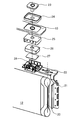
도 1은 본 발명의 실시형태의 밀폐전지의 사시도이다.
도 2는 도 1에 나타낸 밀폐전지의 외부단자의 분해 사시도이다.
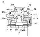
도 3은 도 1에 나타낸 밀폐전지의 외부단자의 단면도이다.
도 4는 본 발명의 실시형태의 단자마개의 단면도이다.
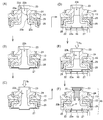
도 5는 본 발명의 실시형태의 밀폐전지의 외부단자의 조립 공정을 순서에 따라 나타내는 단면도이다.
도 6a는 종래 예의 밀폐전지의 외부단자의 단면도이고, 도 6b는 다른 종래 예의 밀폐전지의 외부단자의 단면도이다.1 is a perspective view of a sealed battery according to an embodiment of the present invention.
FIG. 2 is an exploded perspective view of an external terminal of the sealed battery shown in FIG. 1.
3 is a cross-sectional view of an external terminal of the sealed battery shown in FIG. 1.
It is sectional drawing of the terminal plug of embodiment of this invention.
Fig. 5 is a cross-sectional view showing in sequence the assembling step of the external terminal of the sealed battery according to the embodiment of the present invention.
6A is a cross-sectional view of an external terminal of a conventional sealed battery, and FIG. 6B is a cross-sectional view of an external terminal of a conventional sealed battery.
이하에, 본 발명을 실시하기 위한 형태를 도면을 이용하여 상세하게 설명하지만, 이하에서는 정극극판 측의 정극외부단자를 예를 들어 설명한다. 본 실시형태의 밀폐전지(10)는, 도 1 및 도 2에 나타내는 바와 같이, 외장캔(11) 내에 정극극판 및 부극극판이 감겨져 편평한 모양으로 눌려진 권회전극체(12)가 외장캔(11)의 캔축방향에 대해 가로방향으로 수납되어 있고, 봉구판(13)에 의해 외장캔(11)의 개구가 봉구되어 있다. 또, 봉구판(13)에는 가스배출밸브(14) 및 전해액 주입구멍(도시생략) 및 그 봉지재(15)가 설치되어 있다. 가스배출밸브(14)는 전류차단기구의 작동압보다 높은 가스압이 가해졌을 때에 개방된다.EMBODIMENT OF THE INVENTION Hereinafter, although the form for implementing this invention is demonstrated in detail using drawing, below, the positive electrode outer terminal of the positive electrode plate side is demonstrated to an example. In the sealed
또, 봉구판(13)에는 밀폐전지(10)의 바깥쪽에 정극외부단자(16)와 부극외부단자(17)가 형성되어 있다. 이 정극외부단자(16) 및 부극외부단자(17)는 밀폐전지를 단독으로 사용하는지, 직렬접속 내지 병렬접속으로 사용하는지 등에 따라 적당한 형상의 단자판, 외부접속단자 등(도시생략)을 장착하여 사용된다. 또한, 이하에서는 정극극판용 정극외부단자(16)의 구성에 대해 설명한다.In the sealing
도 2 및 도 3에 나타내는 바와 같이, 권회전극체(12)의 한쪽 단면으로부터 돌출한 예를 들면 복수의 정극심체(20)에는 집전탭(21)이 접속되어 있다. 집전탭(21)에서는 집전체(22)가 연장해 있다. 접속단자(23)는 통부(23a)를 구비하고, 내부에 관통구멍(23b)이 형성되어 있다. 그리고, 접속단자(23)의 통부(23a)는 개스킷(24), 봉구판(13), 절연판(25) 및 봉구체탭(26)에 각각 형성된 구멍 내에 삽입되고, 선단부(23c)가 스웨이징(swaging)되어 일체로 고정되어 있다.As shown in FIG. 2 and FIG. 3, for example, a plurality of
또, 봉구체탭(26)의 선단부에는 반전판(27)의 주위가 용접되어 있고, 이 반전판(27)의 중앙부에는 집전체(22)가 레이저 용접에 의해서 용접되어 있다. 또한, 집전체(22) 및 반전판(27)의 주변부에는 집전체(22) 및 반전판(27)의 위치결정 및 주변부의 전기적 절연을 위한 수지제의 집전체 홀더(28)가 배치되어 있다. 그 때문에, 정극심체(20)는 집전탭(21), 집전체(22), 반전판(27) 및 봉구체탭(26)을 통하여 접속단자(23)와 전기적으로 접속되어 있게 된다. 또, 이들 접속단자(23), 개스킷(24), 봉구판(13), 절연판(25), 봉구체탭(26), 반전판(27), 집전체 홀더(28) 및 집전체(22)에 의해서 본 실시형태의 정극외부단자(16)가 형성되어 있다.In addition, the periphery of the
여기서는, 반전판(27) 및 집전체(22)가 본 발명의 전류차단기구(18)를 형성한다. 즉, 집전체(22)에는 레이저 용접 개소의 주위에 환상으로 홈(22a)이 형성되고, 환상으로 두께가 얇은 부분이 형성되어 있다. 반전판(27)은 외장캔(11) 내의 압력이 증가하면 접속단자(23)의 관통구멍(23b) 측으로 팽창하게 되어 있고, 반전판(27)의 중앙부에는 집전체(22)가 용접되어 있기 때문에, 외장캔(11) 내의 압력이 소정값을 넘으면 집전체(22)가 환상의 홈(22a)의 부분에서 파단하기 때문에, 반전판(27)과 집전체(22)와의 사이의 전기적 접속이 차단되게 되어 있다. 또한, 전류차단기구(18)로서는, 상술한 구성 이외에, 반전판(27)에 용접되고, 이 용접부의 주위를 집전체에 용접한 금속박으로 이루어진 것을 사용하여, 외장캔(11) 내부의 압력이 높아져 반전판(27)이 변형했을 때에 금속박이 파단하는 구성인 것도 채용할 수 있다.Here, the inverting
또, 접속단자(23)에 형성된 관통구멍(23b)은 외장캔(11)의 외부 측에 대경부(23d)가, 상기 외장캔(11)의 내부 측에 소경부(23e)가 각각 형성되어 있다. 이 접속단자(23)의 관통구멍(23b) 내에는, 도 3에 나타낸 바와 같이, 고무제의 단자마개(30)가 강고하게 봉지되어 있다. 단자마개(30)는, 도 4에 나타낸 바와 같이, 상단부에 접속단자(23)의 관통구멍(23b)의 소경부(23e)보다 큰 지름이고 대경부(23d)보다 작은 지름의 머리부분(31)과, 하단부에 머리부분(31)보다 작은 지름이고 관통구멍(23b)의 소경부(23e)보다 큰 지름의 돌출부(32)와, 이 돌출부(32)에서 테이퍼 모양으로 작아지도록 형성된 계지부(33)와, 중간에 접속단자(23)의 관통구멍(23b)의 소경부(23e)와 대략 동일한 지름이고 이 소경부(23e)의 길이와 실질적으로 동일한 길이의 연결부(34)를 구비하고 있다. 그리고, 단자마개(30)는 머리부분(31)이 접속단자(23)의 관통구멍(23b)의 대경부(23d) 측에 위치하고, 계지부(33)가 접속단자(23)의 관통구멍(23b)의 소경부(23e)의 단부에서 돌출하도록 관통구멍(23b)에 장착되어 있다. 또한, 단자마개(30)의 머리부분(31)의 표면에는 머리부분(31)의 두께를 얇게 하여도 강도를 크게 하기 위해, 예를 들면 알루미늄 금속제의 금속판(35)이 설치되어 있다.In the through-
이 금속판(35)은, 예를 들면 레이저 용접에 의해서 접속단자(23)에 용접 고정할 수 있다. 단자마개(30)는 탄성부재로 구성되어 있으므로, 진동 등으로 빠져 떨어질 가능성이 있지만, 금속판(35)을 접속단자(23)에 용접 고정함으로써, 보다 강고하게 단자마개(30)에 의해서 관통구멍(23b)을 봉지할 수 있게 된다.This
이 정극외부단자(16)의 조립공정을 도 5를 이용하여 공정순서로 설명한다. 처음으로, 봉구판(13)의 위쪽에 개스킷(24) 및 접속단자(23)를 배치하고, 접속단자(23)의 통부(23a)를 개스킷(24) 및 봉구판(13)의 각각에 형성되어 있는 개구 내에 삽입하여 통과시킨다. 다음으로, 접속단자(23)의 통부(23a)에 개스킷(24)과는 반대 측으로부터 절연판(25) 및 봉구체탭(26)의 각각에 형성되어 있는 개구를 삽입하여 통과시킨다. 그 후, 접속단자(23)의 통부(23a)의 선단부(23c)를 스웨이징함으로써, 접속단자(23)와, 개스킷(24)과, 봉구판(13)과, 절연판(25)과, 봉구체탭(26)을 일체로 고정한다(도 5의 (A)).The assembling process of the positive electrode
다음으로, 봉구체탭(26)의 주연부에 반전판(27)의 주위를 완전하게 밀폐하도록 용접한다(도 5의 (B)). 또한, 여기서는, 반전판(27)으로서는 얇은 알루미늄제의 판을 하부가 돌출하도록 성형처리한 것을 이용했다. 봉구체탭(26)과 반전판(27)과의 사이의 용접법으로서는 레이저 용접법 내지 초음파 용접법을 채용할 수 있다. 그 후, 접속단자(23)의 꼭대기부에서 관통구멍(23b) 내로 소정압력의 가스, 예를 들면 N2가스 등의 불활성 가스나 건조공기를 도입하고, 봉구체탭(26)과 반전판(27)과의 사이의 용접부의 밀봉 상태를 검사한다(도 5의 (C)). 이 검사로 밀봉상태가 완전하지 않다고 판정된 것은 배제한다.Next, it welds so that the circumference | surroundings of the
봉구체탭(26)과 반전판(27)과의 사이의 용접부가 정상으로 판정된 것에 대해서는 반전판(27)에 수지제의 집전체 홀더(28)를 맞닿게 하고, 집전체 홀더(28)와 절연판(25)을 랫치(latch) 고정하며, 다음으로, 집전체(22)의 홈(22a)으로 둘러싸인 영역과 반전판(27)을 레이저 용접법 내지 초음파 용접법에 따라 용접한다(도 5의 (D)). 이것에 의해 본 실시형태의 전류차단기구(18)가 완성된다.In the case where the weld between the sealing
이 용접에 의해서 봉구체탭(26)과 반전판(27)과의 사이의 용접 개소가 악영향을 받을 가능성이 있기 때문에, 재차 접속단자(23)의 꼭대기부에서 관통구멍(23b) 내로 소정 압력의 가스를 도입하고, 봉구체탭(26)과 반전판(27)과의 사이의 용접부의 밀봉상태를 검사한다(도 5의 (E)). 이 2번째 검사에 의해서, 본 실시형태의 정극외부단자(16)의 신뢰성이 크게 향상한다. 그러나, 이 2번째 검사는 반드시 필요한 공정이 아니며, 필요에 따라서 행하면 된다.Since the welding location between the sealing
다음으로, 접속단자(23)의 관통구멍(23b) 내에 단자마개(30)를 삽입하고(도 5의 (F)), 적당한 단자마개(30)의 금속판(35)을, 예를 들면 레이저 용접에 의해서, 접속단자(23)에 용접 고정함으로써, 본 실시형태의 정극극판용 정극외부단자(16)가 완성된다. 이 정극극판용 정극외부단자(16)는, 이 상태로 사용해도 되지만, 밀폐전지(10)를 단독으로 사용할지, 직렬접속 내지 병렬접속으로 사용할지 등에 따라서 적당한 형상의 단자판, 외부접속단자 등(도시생략)을 장착하여 사용하면 된다.Next, the
또한, 여기서는 정극극판용 정극외부단자(16)의 구성에 대해 설명했지만, 부극극판용 부극외부단자(17)의 구성으로서도 채용할 수도 있다. 다만, 정극극판용 정극외부단자(16)로서 상술의 전류차단기구(18)를 구비하고 있는 구성을 채용한 경우, 부극극판용 부극외부단자(17)에 전류차단기구를 채용할 필요는 없기 때문에, 부극극판용 부극외부단자(17)로서는 보다 간단한 구성인 것을 채용할 수 있다.In addition, although the structure of the positive electrode
본 실시형태의 밀폐전지(10)를 완성시키는 데에는 정극외부단자(16)에 장착되어 있는 권회전극체(12)를 외장캔(11) 내에 삽입하고, 봉구판(13)을 외장캔(11)의 개구에 끼워 맞춰서, 이 끼워맞춤부분을 레이저 용접하여 봉구하고, 또한, 전해액 주입구멍(도시생략)으로부터 소정량의 전해액을 주입한 후, 전해액 주입구멍의 봉지재(15)에 의해서 봉지하면 된다. 이 전해액의 주입시에는 외장캔(11), 봉구판(13) 등의 표면의 전해액이 부착할 우려가 있기 때문에, 이러한 표면을 수세하여 청정화할 필요가 있다. 그렇지만, 본 실시형태의 밀폐전지(10)에서는 접속단자(23)의 관통구멍(23b) 내에 단자마개(30)가 강고하게 삽입되어 있기 때문에, 전해액이나 세정수가 접속단자(23)의 관통구멍(23b) 내에 침입할 우려가 없기 때문에, 전류차단기구(18)의 동작에 악영향을 미치는 것이 없어진다.To complete the sealed
또, 본 실시형태의 밀폐전지(10)에서는 전류차단기구(18)의 전지 외측에 대응하는 측의 공간은 완전하게 밀폐되어 있지만, 어떠한 원인에 의해서 외장캔(11) 내의 압력이 증가하여도 이상시에는 전지 내부에서 발생하는 가스압이 매우 커지기 때문에, 전류차단기구(18)의 전지 외측에 대응하는 측의 밀폐공간 내의 압력이 동시에 동일하게 증가하는 경우는 거의 없으며, 전류차단기구(18)의 전지 외측에 대응하는 측의 공간이 밀폐되어 있어도 문제가 되지 않는다.In the sealed
10 … 밀폐전지 11 … 외장캔 12 … 권회전극체 13 … 봉구판 14 … 가스배출밸브 15 … 봉지재 15 … 전해액 주입구멍의 봉지재 16 … 정극외부단자 17 … 부극외부단자 18 … 전류차단기구 20 … 정극심체 21 … 집전탭 22 … 집전체 22a … 홈 23 … 접속단자 23a … 통부 23b … 관통구멍 23b … 관통구멍 23c … 선단부 23d … 대경부 23e … 소경부 24 … 개스킷 25 … 절연판 26 … 봉구체탭 27 … 반전판 28 … 집전체 홀더 30 … 단자마개 31 … 머리부분 32 … 돌출부 33 … 계지부 34 … 연결부 35 … 금속판10...
Claims (8)
상기 외장캔 내에 수용된 정극집전판(正極集電板) 및 부집전판극(負極集電板)을 각각 구비하는 정극극판(正極極板) 및 부극극판(負極極板)을 가지는 전극체와,
상기 외장캔의 개구를 봉구(封口)하고 있는 봉구판과,
상기 봉구판에 장착된 접속단자를 가지는 외부단자를 구비한 밀폐전지로서,
상기 접속단자와 상기 전극체는 전기적으로 접속되고,
상기 접속단자와 상기 전극체를 전기적으로 접속하는 도전(導電) 경로의 사이에 상기 외장캔 내부의 압력의 상승에 대응하여 전류를 차단하는 전류차단기구가 설치되며,
상기 접속단자는 그 내부에 상기 전류차단기구의 전지 외측에 대응하는 측의 공간과 이어지는 관통구멍이 형성되고,
상기 관통구멍은 상기 전류차단기구와의 사이에 밀폐공간이 형성되도록 탄성부재로 이루어진 단자마개에 의해서 봉지(封止)되어 있는 것을 특징으로 하는 밀폐전지.Exterior cans having an opening,
An electrode body having a positive electrode plate and a negative electrode plate each having a positive electrode current collector plate and a negative current collector electrode housed in the outer can;
A sealing plate sealing the opening of the outer can;
A sealed battery having an external terminal having a connection terminal mounted on the sealing plate,
The connection terminal and the electrode body are electrically connected,
Between the connection terminal and the conductive path for electrically connecting the electrode body, a current interruption mechanism is provided for interrupting the current in response to the increase in the pressure inside the outer can.
The connection terminal has a through hole connected therein with a space on the side corresponding to the outside of the battery of the current interrupt mechanism,
The through-hole is sealed by a terminal plug made of an elastic member so as to form a sealed space between the current blocking mechanism.
상기 단자마개는 탄성부재와 금속판으로 이루어지고, 상기 금속판은 상기 접속단자에 용접되어 있는 것을 특징으로 하는 밀폐전지.The method according to claim 1,
The terminal plug is made of an elastic member and a metal plate, the metal plate is sealed battery, characterized in that welded to the connecting terminal.
상기 접속단자에 형성된 관통구멍은 상기 외장캔의 외부 측에 대경부(大徑部)가, 상기 외장캔의 내부 측에 소경부(小徑部)가 형성되어 있고,
상기 단자마개는 상단부에 상기 관통구멍의 소경부보다 큰 지름이고 상기 관통구멍의 대경부보다 작은 지름의 머리부분과, 하단부에 상기 머리부분보다 작은 지름이고 상기 관통구멍의 소경부보다 큰 지름의 돌출부 및 상기 돌출부에서 테이퍼 모양으로 작아지도록 형성된 계지부(係止部)와, 중간에 상기 관통구멍의 소경부와 대략 동일한 지름이고 상기 관통구멍의 소경부의 길이와 실질적으로 동일한 길이의 연결부를 구비하고, 상기 머리부분이 상기 관통구멍의 대경부 측에 위치하며, 상기 계지부가 상기 관통구멍의 소경부의 단부보다 돌출하도록 상기 관통구멍에 장착되어 있는 것을 특징으로 하는 밀폐전지.The method according to claim 1,
The through hole formed in the connecting terminal has a large diameter portion on the outer side of the outer can and a small diameter portion on the inner side of the outer can.
The terminal plug has a head having a diameter larger than the small diameter portion of the through hole at the upper end and a diameter smaller than the large diameter portion of the through hole, and a protrusion having a diameter smaller than the small diameter portion at the lower end and larger than the small diameter portion of the through hole. And a locking portion formed so as to be tapered in the projection portion, and a connecting portion having a diameter substantially equal to that of the small diameter portion of the through hole and having a length substantially equal to the length of the small diameter portion of the through hole. And the head portion is located at the side of the large diameter portion of the through hole, and the locking portion is attached to the through hole such that the locking portion protrudes from an end portion of the small diameter portion of the through hole.
상기 전류차단기구는 상기 외장캔 내부의 압력의 상승에 대응하여 변형하고, 상기 접속단자와 상기 전극체와의 사이의 전기적 접속을 차단하는 것을 특징으로 하는 밀폐전지.The method according to any one of claims 1 to 3,
And the current interruption mechanism deforms in response to an increase in pressure in the outer can, and cuts off an electrical connection between the connection terminal and the electrode body.
상기 접속단자에 상기 관통구멍의 한쪽의 단부를 밀봉하도록 전류차단기구를 장착하는 제1 공정과,
상기 관통구멍의 다른 쪽의 단부로부터 가스를 보내어 상기 접속단자와 상기 전류차단기구와의 사이의 공기 누출을 검사하는 제2 공정과,
상기 관통구멍 내에 탄성부재로 이루어진 단자마개를 삽입하는 제3 공정을 구비하는 것을 특징으로 하는 밀폐전지의 제조방법.External terminals provided with an outer can having an opening, an electrode body having a positive electrode plate and a negative electrode plate, a positive electrode current collector plate and a negative electrode current collector plate respectively mounted on the positive electrode plate and the negative electrode plate, and connection terminals having through holes formed therein, and an electrolyte main In the manufacturing method of a sealed battery provided with a sealing plate having a liquid sphere,
A first step of attaching a current interruption mechanism to seal said one end of said through hole to said connecting terminal;
A second step of inspecting air leakage between the connection terminal and the current interruption mechanism by sending gas from the other end of the through hole;
And a third step of inserting a terminal plug made of an elastic member into the through hole.
상기 제3 공정에서 상기 단자마개로서 탄성부재와 금속판으로 이루어지는 것을 이용하여, 상기 관통구멍 내에 탄성부재로 이루어진 단자마개를 삽입한 후, 상기 금속판을 상기 접속단자에 용접 고정하는 것을 특징으로 하는 밀폐전지의 제조방법.The method according to claim 5,
A sealed battery, characterized in that the terminal plug is formed of an elastic member and a metal plate as the terminal plug in the third step, and then the metal plate is welded and fixed to the connection terminal after inserting the terminal plug made of the elastic member into the through hole. Manufacturing method.
상기 전류차단기구가 봉구체탭과, 반전판과, 파단부를 가지는 집전체로 이루어지고, 상기 봉구체탭에 상기 반전판을 장착한 후, 상기 관통구멍의 다른 쪽의 단부로부터 가스를 보내어 검사하는 공정을 구비하는 것을 특징으로 하는 밀폐전지의 제조방법.The method according to claim 5 or 6,
The current interruption mechanism includes a current collector having a sealing body tab, a reverse plate, and a breakage portion. After the mounting of the inversion plate on the sealing body tab, gas is sent from the other end of the through hole. The manufacturing method of the sealed battery characterized by including the process.
상기 반전판에 상기 집전체의 파단부를 장착한 후, 상기 관통구멍의 다른 쪽의 단부로부터 가스를 보내어 검사하는 공정을 구비하는 것을 특징으로 하는 밀폐전지의 제조방법.The method according to claim 7,
And attaching a break of the current collector to the inverting plate, and then sending gas from the other end of the through hole to inspect the sealed plate.
Applications Claiming Priority (2)
| Application Number | Priority Date | Filing Date | Title |
|---|---|---|---|
| JP2009055803A JP5430978B2 (en) | 2009-03-10 | 2009-03-10 | Sealed battery and manufacturing method thereof |
| JPJP-P-2009-055803 | 2009-03-10 |
Publications (1)
| Publication Number | Publication Date |
|---|---|
| KR20100102040A true KR20100102040A (en) | 2010-09-20 |
Family
ID=42718289
Family Applications (1)
| Application Number | Title | Priority Date | Filing Date |
|---|---|---|---|
| KR1020100012739A KR20100102040A (en) | 2009-03-10 | 2010-02-11 | Enclosed battery and method of manufacturing thereof |
Country Status (4)
| Country | Link |
|---|---|
| US (3) | US8304109B2 (en) |
| JP (1) | JP5430978B2 (en) |
| KR (1) | KR20100102040A (en) |
| CN (1) | CN101834306B (en) |
Cited By (1)
| Publication number | Priority date | Publication date | Assignee | Title |
|---|---|---|---|---|
| US9537121B2 (en) | 2011-03-18 | 2017-01-03 | Samsung Sdi Co., Ltd. | Secondary battery and secondary battery pack having a flexible collecting tab extending through a cap plate |
Families Citing this family (69)
| Publication number | Priority date | Publication date | Assignee | Title |
|---|---|---|---|---|
| JPH0838274A (en) * | 1994-08-02 | 1996-02-13 | Yasuyori Kakumoto | Furniture |
| US8420254B2 (en) * | 2007-12-25 | 2013-04-16 | Byd Co. Ltd. | End cover assembly for an electrochemical cell |
| JP2012059365A (en) * | 2010-09-03 | 2012-03-22 | Sanyo Electric Co Ltd | Terminal for sealed battery and method of manufacturing the same |
| US20120177978A1 (en) * | 2011-01-11 | 2012-07-12 | Sungbae Kim | Secondary battery, method of assembling the same, and battery pack including the secondary battery |
| KR101244735B1 (en) * | 2011-04-05 | 2013-03-18 | 로베르트 보쉬 게엠베하 | Rechargeable battery |
| JP5663415B2 (en) * | 2011-06-24 | 2015-02-04 | 日立オートモティブシステムズ株式会社 | Secondary battery |
| JP5578371B2 (en) * | 2011-11-09 | 2014-08-27 | トヨタ自動車株式会社 | Sealed battery and discharge method thereof |
| CN103959512A (en) | 2011-11-23 | 2014-07-30 | 丰田自动车株式会社 | Secondary battery manufacturing method and secondary battery |
| JP6115084B2 (en) * | 2011-11-29 | 2017-04-19 | 株式会社Gsユアサ | Electricity storage element |
| JP6175758B2 (en) * | 2011-11-29 | 2017-08-09 | 株式会社Gsユアサ | Electricity storage element |
| WO2013093987A1 (en) | 2011-12-19 | 2013-06-27 | トヨタ自動車株式会社 | Battery |
| JP5888730B2 (en) * | 2012-01-27 | 2016-03-22 | 三洋電機株式会社 | Prismatic secondary battery |
| JP5886059B2 (en) * | 2012-01-27 | 2016-03-16 | 三洋電機株式会社 | Rectangular secondary battery and manufacturing method thereof |
| JP5893935B2 (en) * | 2012-01-27 | 2016-03-23 | トヨタ自動車株式会社 | Sealed battery |
| JP6030880B2 (en) * | 2012-01-27 | 2016-11-24 | 三洋電機株式会社 | Prismatic secondary battery |
| JP5788815B2 (en) * | 2012-01-27 | 2015-10-07 | 三洋電機株式会社 | Prismatic secondary battery |
| JP5611251B2 (en) | 2012-01-27 | 2014-10-22 | トヨタ自動車株式会社 | Sealed secondary battery |
| JP5916401B2 (en) * | 2012-01-27 | 2016-05-11 | 三洋電機株式会社 | Non-aqueous electrolyte secondary battery, manufacturing method thereof, and vehicle including the non-aqueous electrolyte secondary battery |
| FR2989836B1 (en) * | 2012-04-24 | 2014-05-23 | Commissariat Energie Atomique | TRAVERSEE FORMING TERMINAL FOR LITHIUM ELECTROCHEMICAL ACCUMULATOR AND ASSOCIATED ACCUMULATOR. |
| WO2013164897A1 (en) | 2012-05-02 | 2013-11-07 | トヨタ自動車株式会社 | Hermetic secondary battery |
| WO2013175619A1 (en) * | 2012-05-25 | 2013-11-28 | 日立ビークルエナジー株式会社 | Rectangular secondary battery |
| US8991232B2 (en) | 2012-07-17 | 2015-03-31 | Sanyo Electric Co., Ltd. | Sealing plate for prismatic secondary battery, method for producing the same, and prismatic secondary battery using the same |
| US9263719B2 (en) | 2012-07-17 | 2016-02-16 | Sanyo Electric Co., Ltd. | Sealing plate for prismatic secondary battery and prismatic secondary battery using the sealing plate |
| US9017843B2 (en) * | 2012-07-17 | 2015-04-28 | Sanyo Electric Co., Ltd. | Prismatic secondary battery |
| JP5716713B2 (en) * | 2012-08-07 | 2015-05-13 | トヨタ自動車株式会社 | Sealed battery |
| JP6022257B2 (en) * | 2012-08-09 | 2016-11-09 | 三洋電機株式会社 | Non-aqueous electrolyte secondary battery and manufacturing method thereof |
| JP6005172B2 (en) | 2012-09-28 | 2016-10-12 | 日立オートモティブシステムズ株式会社 | Prismatic secondary battery |
| JP5958756B2 (en) * | 2012-10-09 | 2016-08-02 | トヨタ自動車株式会社 | Leakage inspection method for current cutoff valve |
| JP5776663B2 (en) * | 2012-10-16 | 2015-09-09 | トヨタ自動車株式会社 | Non-aqueous electrolyte secondary battery |
| JP5733287B2 (en) * | 2012-10-19 | 2015-06-10 | トヨタ自動車株式会社 | Pressure type current interrupter for sealed battery |
| JP6112338B2 (en) * | 2012-10-24 | 2017-04-12 | トヨタ自動車株式会社 | Secondary battery |
| KR101726110B1 (en) * | 2012-11-15 | 2017-04-11 | 제이에무에나지 가부시키가이샤 | Electricity storage device and electricity storage module |
| JP5867376B2 (en) * | 2012-12-07 | 2016-02-24 | トヨタ自動車株式会社 | Sealed battery |
| JP5821835B2 (en) | 2012-12-27 | 2015-11-24 | トヨタ自動車株式会社 | Sealed battery and method for manufacturing sealed battery |
| KR101666255B1 (en) * | 2013-01-08 | 2016-10-13 | 삼성에스디아이 주식회사 | Rechargeable battery |
| KR20140089979A (en) * | 2013-01-08 | 2014-07-16 | 삼성에스디아이 주식회사 | Battery module |
| JP6008200B2 (en) * | 2013-05-02 | 2016-10-19 | トヨタ自動車株式会社 | Secondary battery |
| US10109889B2 (en) | 2013-07-01 | 2018-10-23 | Sanyo Electric Co., Ltd. | Non-aqueous electrolyte secondary battery |
| JP6289843B2 (en) * | 2013-09-17 | 2018-03-07 | 株式会社東芝 | Battery and battery manufacturing method |
| JP6107568B2 (en) | 2013-09-25 | 2017-04-05 | トヨタ自動車株式会社 | Secondary battery |
| US9478377B2 (en) * | 2013-10-16 | 2016-10-25 | Kabushiki Kaisha Toyota Jidoshokki | Current interruption device and electricity storage device using the same |
| JP6204850B2 (en) * | 2013-10-16 | 2017-09-27 | 株式会社豊田自動織機 | Current interrupting device and manufacturing method thereof |
| KR102153044B1 (en) * | 2013-11-11 | 2020-09-07 | 삼성전자주식회사 | Flexible secondary battery |
| JP6198680B2 (en) * | 2014-06-17 | 2017-09-20 | イーグル工業株式会社 | Current interrupt device, power storage device, method of manufacturing current interrupt device, and method of manufacturing power storage device |
| JP6308071B2 (en) | 2014-08-07 | 2018-04-11 | 三洋電機株式会社 | Rectangular secondary battery and method for manufacturing the same |
| JP6446966B2 (en) * | 2014-10-02 | 2019-01-09 | 株式会社豊田自動織機 | Power storage device with current interrupt device |
| JP6542529B2 (en) | 2014-12-19 | 2019-07-10 | 三洋電機株式会社 | Square secondary battery and assembled battery using the same |
| KR101704162B1 (en) | 2015-01-20 | 2017-02-07 | 현대자동차주식회사 | Improved pouch battery overcharging safety |
| JP6004020B2 (en) * | 2015-01-26 | 2016-10-05 | 三洋電機株式会社 | Sealed battery and manufacturing method thereof |
| DE102016107971A1 (en) * | 2015-05-14 | 2016-11-17 | Toyota Jidosha Kabushiki Kaisha | secondary battery |
| JP6522418B2 (en) | 2015-05-15 | 2019-05-29 | 三洋電機株式会社 | Rectangular secondary battery, battery assembly using the same, and method of manufacturing the same |
| JP6565412B2 (en) | 2015-07-21 | 2019-08-28 | 三洋電機株式会社 | Secondary battery |
| JP6597014B2 (en) | 2015-07-21 | 2019-10-30 | 三洋電機株式会社 | Secondary battery |
| JP6547487B2 (en) * | 2015-07-22 | 2019-07-24 | 株式会社豊田自動織機 | Power storage device module |
| JP6436875B2 (en) * | 2015-07-27 | 2018-12-12 | 株式会社豊田自動織機 | Current interrupt device and power storage device using the same |
| KR102392380B1 (en) | 2015-08-19 | 2022-04-29 | 삼성에스디아이 주식회사 | Secondary battery |
| JP2017045660A (en) * | 2015-08-27 | 2017-03-02 | 株式会社豊田自動織機 | Power storage device |
| KR102397217B1 (en) | 2015-09-03 | 2022-05-12 | 삼성에스디아이 주식회사 | Battery pack |
| JP6529881B2 (en) * | 2015-09-30 | 2019-06-12 | 株式会社豊田自動織機 | Power storage device |
| JP6720547B2 (en) * | 2016-01-18 | 2020-07-08 | 株式会社Gsユアサ | Power storage device |
| JP6837796B2 (en) | 2016-09-30 | 2021-03-03 | 三洋電機株式会社 | Non-aqueous electrolyte secondary battery |
| CN108092342B (en) * | 2016-11-21 | 2021-08-13 | 佛山市顺德区顺达电脑厂有限公司 | Charging seat and battery connecting module thereof |
| US11063328B2 (en) * | 2017-01-25 | 2021-07-13 | Sanyo Electric Co., Ltd. | Secondary battery including insulating member with grooves |
| JP6957164B2 (en) * | 2017-02-27 | 2021-11-02 | 三洋電機株式会社 | Rechargeable battery |
| JP6972834B2 (en) * | 2017-09-22 | 2021-11-24 | 株式会社Gsユアサ | Power storage element |
| JP6905068B2 (en) * | 2017-09-27 | 2021-07-21 | 株式会社豊田自動織機 | Current cutoff device and power storage device |
| CN112331972B (en) * | 2020-02-24 | 2022-01-28 | 宁德时代新能源科技股份有限公司 | Top cover assembly, single battery, battery module, battery pack and device |
| CN111425635B (en) * | 2020-03-31 | 2022-04-05 | 威睿电动汽车技术(宁波)有限公司 | Thermal runaway anti-backfire pressure release valve and electric automobile |
| CN114300772B (en) * | 2021-12-30 | 2024-02-13 | 淮南市通霸蓄电池有限公司 | Electrolyte level indicating device for explosion-proof special lead-acid storage battery |
Family Cites Families (18)
| Publication number | Priority date | Publication date | Assignee | Title |
|---|---|---|---|---|
| US3529463A (en) | 1968-11-14 | 1970-09-22 | Gilmore Ind Inc | Method and apparatus for testing battery casings for leaks |
| US3793876A (en) * | 1972-08-10 | 1974-02-26 | Gould Inc | Battery terminal leak detector |
| US4099404A (en) | 1974-05-31 | 1978-07-11 | General Battery Corporation | Automatic air leak testing apparatus and method for batteries |
| US4398413A (en) * | 1981-05-18 | 1983-08-16 | Medtronic, Inc. | Leak detection for hermetic enclosures |
| US4913986A (en) | 1983-09-28 | 1990-04-03 | Medtronic, Inc. | Battery fill-post seal arrangement for hermeticity leakage testing |
| JP2897104B2 (en) * | 1994-06-03 | 1999-05-31 | 古河電池株式会社 | Manufacturing method of sealed alkaline storage battery |
| US5602328A (en) * | 1995-12-18 | 1997-02-11 | General Motors Corporation | Battery leak testing method |
| JP3351243B2 (en) * | 1996-07-02 | 2002-11-25 | 松下電器産業株式会社 | Sealed alkaline storage battery and its manufacturing method |
| JPH10172618A (en) * | 1996-12-13 | 1998-06-26 | Keihin Rika Kogyo:Kk | Method for inspecting lithium ion |
| US6132900A (en) * | 1996-12-25 | 2000-10-17 | Matsushita Electric Industrial Co., Ltd. | Method of production of non-aqueous electrolyte battery and seal plate thereof |
| JP2004303739A (en) * | 1996-12-25 | 2004-10-28 | Matsushita Electric Ind Co Ltd | Rectangular non-aqueous electrolyte battery |
| JPH11329405A (en) | 1998-05-21 | 1999-11-30 | At Battery:Kk | Nonaqueous electrolyte secondary battery |
| JP4671462B2 (en) * | 2000-02-22 | 2011-04-20 | パナソニック株式会社 | Airtight inspection method for nickel metal hydride secondary battery |
| US6844110B2 (en) * | 2000-05-24 | 2005-01-18 | Ngk Insulators, Ltd. | Lithium secondary cell and assembly thereof |
| US6673489B2 (en) * | 2001-12-28 | 2004-01-06 | Quallion Llc | Electric battery assembly and method of manufacture |
| JP4843947B2 (en) * | 2005-01-19 | 2011-12-21 | トヨタ自動車株式会社 | Sealed battery manufacturing method and airtightness inspection apparatus |
| JP5084205B2 (en) | 2006-08-11 | 2012-11-28 | 三洋電機株式会社 | Nonaqueous electrolyte secondary battery |
| JP5147206B2 (en) | 2006-08-11 | 2013-02-20 | 三洋電機株式会社 | Nonaqueous electrolyte secondary battery |
-
2009
- 2009-03-10 JP JP2009055803A patent/JP5430978B2/en active Active
-
2010
- 2010-02-11 KR KR1020100012739A patent/KR20100102040A/en not_active Application Discontinuation
- 2010-02-24 US US12/711,618 patent/US8304109B2/en active Active
- 2010-03-03 CN CN201010129488.XA patent/CN101834306B/en active Active
-
2012
- 2012-10-08 US US13/646,811 patent/US9368764B2/en active Active
- 2012-10-08 US US13/646,792 patent/US8480763B2/en active Active
Cited By (1)
| Publication number | Priority date | Publication date | Assignee | Title |
|---|---|---|---|---|
| US9537121B2 (en) | 2011-03-18 | 2017-01-03 | Samsung Sdi Co., Ltd. | Secondary battery and secondary battery pack having a flexible collecting tab extending through a cap plate |
Also Published As
| Publication number | Publication date |
|---|---|
| CN101834306B (en) | 2014-04-23 |
| JP5430978B2 (en) | 2014-03-05 |
| US9368764B2 (en) | 2016-06-14 |
| US20100233529A1 (en) | 2010-09-16 |
| US20130067727A1 (en) | 2013-03-21 |
| US20130067728A1 (en) | 2013-03-21 |
| JP2010212034A (en) | 2010-09-24 |
| US8480763B2 (en) | 2013-07-09 |
| US8304109B2 (en) | 2012-11-06 |
| CN101834306A (en) | 2010-09-15 |
Similar Documents
| Publication | Publication Date | Title |
|---|---|---|
| KR20100102040A (en) | Enclosed battery and method of manufacturing thereof | |
| JP5084205B2 (en) | Nonaqueous electrolyte secondary battery | |
| US20130196220A1 (en) | Prismatic secondary battery | |
| JP4596289B2 (en) | Sealed battery | |
| JP5507623B2 (en) | Nonaqueous electrolyte secondary battery | |
| US8197963B2 (en) | Lithium ion secondary battery | |
| JP3154279B2 (en) | Rechargeable battery | |
| KR20080058966A (en) | Battery having washer of electrolyte-absorbing property | |
| JP2014032967A (en) | Nonaqueous electrolyte battery | |
| CN103779531A (en) | Current interrupting device of sealed battery | |
| KR101718651B1 (en) | Production method for sealed batteries | |
| JP5742915B2 (en) | Sealed battery and manufacturing method thereof | |
| JP5443922B2 (en) | Non-aqueous electrolyte battery | |
| JP6004020B2 (en) | Sealed battery and manufacturing method thereof | |
| JP5958756B2 (en) | Leakage inspection method for current cutoff valve | |
| JP2020004650A (en) | Secondary battery | |
| KR100277652B1 (en) | Cap Assembly of Secondary Battery | |
| KR20070096641A (en) | Cap assembly and secondary battery having the same and plug for electrolyte pouring hole | |
| KR20060088312A (en) | Cap assembly and lithium ion secondary battery with the same | |
| KR100858806B1 (en) | Battery | |
| KR102561215B1 (en) | Secondary battery | |
| JPH11121017A (en) | Alkaline battery | |
| JP2003217531A (en) | Sealed battery | |
| JPH0636209U (en) | Sealed battery | |
| JP2018147647A (en) | battery |
Legal Events
| Date | Code | Title | Description |
|---|---|---|---|
| WITN | Application deemed withdrawn, e.g. because no request for examination was filed or no examination fee was paid |