KR20100040887A - Closure with membrane and rotatable protective cap - Google Patents
Closure with membrane and rotatable protective cap Download PDFInfo
- Publication number
- KR20100040887A KR20100040887A KR1020107001876A KR20107001876A KR20100040887A KR 20100040887 A KR20100040887 A KR 20100040887A KR 1020107001876 A KR1020107001876 A KR 1020107001876A KR 20107001876 A KR20107001876 A KR 20107001876A KR 20100040887 A KR20100040887 A KR 20100040887A
- Authority
- KR
- South Korea
- Prior art keywords
- closure
- cap
- protective cap
- container
- removal
- Prior art date
- Legal status (The legal status is an assumption and is not a legal conclusion. Google has not performed a legal analysis and makes no representation as to the accuracy of the status listed.)
- Granted
Links
Images


Classifications
-
- B—PERFORMING OPERATIONS; TRANSPORTING
- B65—CONVEYING; PACKING; STORING; HANDLING THIN OR FILAMENTARY MATERIAL
- B65D—CONTAINERS FOR STORAGE OR TRANSPORT OF ARTICLES OR MATERIALS, e.g. BAGS, BARRELS, BOTTLES, BOXES, CANS, CARTONS, CRATES, DRUMS, JARS, TANKS, HOPPERS, FORWARDING CONTAINERS; ACCESSORIES, CLOSURES, OR FITTINGS THEREFOR; PACKAGING ELEMENTS; PACKAGES
- B65D47/00—Closures with filling and discharging, or with discharging, devices
- B65D47/04—Closures with discharging devices other than pumps
- B65D47/20—Closures with discharging devices other than pumps comprising hand-operated members for controlling discharge
- B65D47/26—Closures with discharging devices other than pumps comprising hand-operated members for controlling discharge with slide valves, i.e. valves that open and close a passageway by sliding over a port, e.g. formed with slidable spouts
- B65D47/261—Closures with discharging devices other than pumps comprising hand-operated members for controlling discharge with slide valves, i.e. valves that open and close a passageway by sliding over a port, e.g. formed with slidable spouts having a rotational or helicoidal movement
- B65D47/265—Closures with discharging devices other than pumps comprising hand-operated members for controlling discharge with slide valves, i.e. valves that open and close a passageway by sliding over a port, e.g. formed with slidable spouts having a rotational or helicoidal movement between planar parts
-
- B—PERFORMING OPERATIONS; TRANSPORTING
- B65—CONVEYING; PACKING; STORING; HANDLING THIN OR FILAMENTARY MATERIAL
- B65D—CONTAINERS FOR STORAGE OR TRANSPORT OF ARTICLES OR MATERIALS, e.g. BAGS, BARRELS, BOTTLES, BOXES, CANS, CARTONS, CRATES, DRUMS, JARS, TANKS, HOPPERS, FORWARDING CONTAINERS; ACCESSORIES, CLOSURES, OR FITTINGS THEREFOR; PACKAGING ELEMENTS; PACKAGES
- B65D41/00—Caps, e.g. crown caps or crown seals, i.e. members having parts arranged for engagement with the external periphery of a neck or wall defining a pouring opening or discharge aperture; Protective cap-like covers for closure members, e.g. decorative covers of metal foil or paper
- B65D41/32—Caps or cap-like covers with lines of weakness, tearing-strips, tags, or like opening or removal devices, e.g. to facilitate formation of pouring openings
- B65D41/34—Threaded or like caps or cap-like covers provided with tamper elements formed in, or attached to, the closure skirt
- B65D41/3404—Threaded or like caps or cap-like covers provided with tamper elements formed in, or attached to, the closure skirt with ratchet-and-pawl mechanism between the container and the closure skirt or the tamper element
-
- B—PERFORMING OPERATIONS; TRANSPORTING
- B65—CONVEYING; PACKING; STORING; HANDLING THIN OR FILAMENTARY MATERIAL
- B65D—CONTAINERS FOR STORAGE OR TRANSPORT OF ARTICLES OR MATERIALS, e.g. BAGS, BARRELS, BOTTLES, BOXES, CANS, CARTONS, CRATES, DRUMS, JARS, TANKS, HOPPERS, FORWARDING CONTAINERS; ACCESSORIES, CLOSURES, OR FITTINGS THEREFOR; PACKAGING ELEMENTS; PACKAGES
- B65D51/00—Closures not otherwise provided for
- B65D51/002—Closures to be pierced by an extracting-device for the contents and fixed on the container by separate retaining means
-
- B—PERFORMING OPERATIONS; TRANSPORTING
- B65—CONVEYING; PACKING; STORING; HANDLING THIN OR FILAMENTARY MATERIAL
- B65D—CONTAINERS FOR STORAGE OR TRANSPORT OF ARTICLES OR MATERIALS, e.g. BAGS, BARRELS, BOTTLES, BOXES, CANS, CARTONS, CRATES, DRUMS, JARS, TANKS, HOPPERS, FORWARDING CONTAINERS; ACCESSORIES, CLOSURES, OR FITTINGS THEREFOR; PACKAGING ELEMENTS; PACKAGES
- B65D2401/00—Tamper-indicating means
- B65D2401/15—Tearable part of the closure
Landscapes
- Engineering & Computer Science (AREA)
- Mechanical Engineering (AREA)
- Closures For Containers (AREA)
- Pens And Brushes (AREA)
- Professional, Industrial, Or Sporting Protective Garments (AREA)
- Joints Allowing Movement (AREA)
Abstract
무균의 또는 수분 민감성 매질의 보관 및 제거를 위한 용기 (1) 의 개구의 밀봉을 위한 클로저 (2) 는 액밀식으로 용기에 연결될 수 있는 클로저 캡 (3) 과 액밀식으로 클로저 캡 (3) 의 적어도 하나의 제거 개구 (7) 를 밀봉하는 관통 가능한 자기 밀봉 격막 (self-sealing septum) (20) 을 가질 수 있고, 이 클로저 (2) 는 컷 아웃 (5) 을 갖는 회전 가능하게 장착된 보호 캡 (4) 을 갖는다. 컷 아웃 (5) 은 보호 캡 (4) 에 중심에서 벗어나서 배치되고, 클로저 캡 (4) 은 적어도 하나의 제거 개구 (7) 에 의해 둘러싸이지 않고 보호 캡 (4) 의 컷 아웃 (5) 보다 더 큰 중심에서 벗어난 클로저 영역 (9) 을 갖는다. 클로저 (2) 는 래치 메카니즘을 가지며, 이 메카니즘은 보호 캡 (4) 의 컷 아웃 (5) 이 클로저 캡 (3) 의 제거 개구 (7) 와 동일한 높이 또는 대안적으로는 제거 개구 (7) 로부터 어떠한 간격이 되도록 클로저 캡 (3) 에 대한 보호 캡 (4) 의 배치에 적절하다. 클로저 (2) 는 적어도 하나의 쉽게 조작할 수 없는 보호 수단을 갖는다. The closure 2 for sealing the opening of the container 1 for the storage and removal of sterile or moisture sensitive medium comprises a closure cap 3 which can be connected to the container in a liquid-tight manner and a closure cap 3 in a liquid-tight manner. It may have a penetrating self-sealing septum 20 which seals at least one removal opening 7, which closure 2 is rotatably mounted protective cap having a cutout 5. (4) has. The cutout 5 is disposed off center in the protective cap 4, and the closure cap 4 is not surrounded by the at least one removal opening 7 and is more than the cutout 5 of the protective cap 4. It has a closure region 9 which is out of a large center. The closure 2 has a latching mechanism, which means that the cutout 5 of the protective cap 4 is flush with the removal opening 7 of the closure cap 3 or alternatively from the removal opening 7. It is suitable for the arrangement of the protective cap 4 relative to the closure cap 3 so as to be at any distance. The closure 2 has at least one easily inoperable protective means.
Description
본 발명은 무균 또는 수분 민감성 매질의 보관 및 제거를 위한 용기의 개구의 밀봉을 위한 클로저에 관한 것이며 이 클로저는 액밀식으로 용기에 연결될 수 있는 클로저 캡과 액밀식으로 클로저 캡의 적어도 하나의 제거 개구를 밀봉하는 관통 가능한 자기 밀봉 격막 (self-sealing septum) 을 가질 수 있다. The present invention relates to a closure for sealing of an opening of a container for storage and removal of sterile or moisture sensitive media, the closure being a liquid closure and at least one removal opening of the closure cap in a liquid tight closure. It can have a self-sealing septum that seals the seal.
조사 및 또한 산업적 분석 및 생산 공정과 관련하여, 무균 또는 수분 민감성 매질에 대한 요구가 종종 있는데, 이러한 매질은 장기간에 걸쳐 보관되고 때때로의 사용 또는 본질적으로는 소량의 매질의 연속적인 제거를 위하여 준비되어야 한다. 필요한 양의 매질의 제거는 아직 요구되지 않은 매질의 오염이 가능한한 배제되도록 간단한 방식으로 가능해야 한다. With regard to investigations and also industrial analytical and production processes, there is often a need for sterile or moisture sensitive media, which must be stored for long periods of time and prepared for occasional use or for sequential removal of essentially small amounts of media. do. Removal of the required amount of medium should be possible in a simple manner so that contamination of the medium that is not yet required is eliminated as much as possible.
이를 위해, 예컨대 유리 또는 플라스틱으로 만들어진 병과 같은 적절한 용기를 제거 개구를 갖는 클로저를 통하여 밀봉하는 것이 공지되어 있으며, 이 제거 개구는 격막을 통하여 액밀식으로 밀봉된다. 이러한 용기를 위한 이런 종류의 공지된 클로저는 이를 위해 하나 이상의 제거 개구를 갖고, 이 제거 개구는 용기의 내부를 향하는 측이 하나 이상의 제거 개구를 커버하는 격막에 의해 액밀식으로 커버 또는 밀봉된다. For this purpose, it is known to seal a suitable container, such as a bottle made of glass or plastic, through a closure having a removal opening, which is sealingly sealed through the diaphragm. Known closures of this kind for such containers have one or more removal openings for this purpose, which removal cover is sealed or sealed by a diaphragm which covers the one or more removal openings on the side facing the interior of the container.
용기에 있는 매질을 제거할 수 있게 하기 위해, 격막은 카눌라 (cannular) 를 통하여 관통되고, 필요한 양의 매질이 제거된다. 격막은 유리하게는 용기에 보관되는 매질에 대하여 불활성이고 (용기 재료와 같은 재료) 동시에 매질의 제거 이후 액밀식으로 자동적으로 재밀봉하기 위해 용이하게 관통될 수 있는 재료로 이루어진다. In order to be able to remove the medium in the container, the diaphragm is penetrated through the cannular and the required amount of medium is removed. The diaphragm is advantageously made of a material that is inert to the medium stored in the container (material like container material) and at the same time can be easily penetrated for liquid resealable automatically after removal of the medium.
각각의 경우에 사용되는 재료와 상관없이, 격막의 각각의 관통은 재료에 손상을 남기며, 이는 종종 볼 수 있고, 따라서, 특히 다수의 제거 조작 이후, 반복적으로 관통된 격막에 의한 용기의 액밀 또는 무균 밀봉은 더 이상 신뢰할 수 있게 보장될 수 없다. Regardless of the material used in each case, each penetration of the diaphragm leaves material damaging, which is often seen, and thus, liquid tightness or sterility of the container by the repeatedly penetrated diaphragm, especially after a number of removal operations. Sealing can no longer be reliably guaranteed.
동일한 지점의 격막의 반복되는 관통은 격막이 이 영역에서 더 이상 완전히 신뢰할 수 있게 밀봉하지 못하는 것을 초래할 수 있다는 것이 실제로 발견되었고, 이는 용기에 있는 매질의 무균 및 건조 보관이 더 이상 보장되지 않는 것을 의미한다. 이러한 이유로, 통상적으로 격막의 동일한 영역을 반복적으로 관통하는 것을 회피하고 관통 영역을 용기에 있는 매질의 제거에 사용하는 것을 목적으로 한다. It was actually found that repeated penetration of the diaphragm at the same point could result in the diaphragm no longer being fully reliably sealed in this area, which means that sterile and dry storage of the medium in the container is no longer guaranteed. do. For this reason, it is usually aimed to avoid repeatedly penetrating the same area of the diaphragm and to use the penetrating area for the removal of the medium in the container.
몇몇 분야를 위해 필요한 무균성을 보장하기 위해 그리고 추가적으로 용기의 내부로의 원치않는 수분의 유입을 방지하기 위해, 추가적인 보호 캡을 갖는 이러한 종류의 클로저를 제공하는 것이 실제로부터 알려져 있다. 이러한 보호 캡은 통상적으로 클로저에 조여지거나 또는 눌리게 되고 하나 이상의 제거 개구를 완전히 커버한다. 용기에 있는 매질이 제거될 수 있기 전에, 보호 캡은 격막을 통하여 밀봉되는 제거 개구를 개방하기 위해 반드시 제거되어야 한다. 이러한 종류의 클로저의 취급은 추가적인 보호 캡에 의해 더 어렵게 된다. It is known from practice to provide closures of this kind with additional protective caps to ensure the required sterility for some applications and additionally to prevent the ingress of unwanted moisture into the interior of the container. Such protective caps are typically tightened or pressed into the closure and completely cover one or more removal openings. Before the medium in the container can be removed, the protective cap must be removed to open the removal opening that is sealed through the diaphragm. Handling of this kind of closure is made more difficult with an additional protective cap.
본 발명의 목적은 따라서 용기에 있는 매질이 가능한한 신뢰할 수 있게 환경적 영향에 대하여 보호되고 동시에 신속하고 간단한 매질의 제거가 용이하게 되도록 서두에 나타낸 포괄적인 종류의 클로저를 디자인 하는 것이다. It is therefore an object of the present invention to design a comprehensive kind of closure shown at the outset so that the medium in the container is reliably protected against environmental influences and at the same time facilitates the quick and simple removal of the medium.
이 목적은 클로저가 컷 아웃 (cut-out) 을 가지며 회전 가능하게 장착된 보호 캡을 갖는 본 발명에 따라 달성된다. 회전 가능하게 장착된 보호 캡은 클로저 캡에 배치된 제거 개구를 개방시키기 위해 클로저 또는 클로저 캡으로부터 분리될 필요는 없다. 보호 캡은 단지 보호 캡의 컷 아웃이 지금까지 보호 캡에 의해 커버되었던 영역 내의 클로저 캡의 제거 개구를 개방시켜 매질의 제거를 위해 접근할 수 있을 때까지 회전되어야 한다. 하지만, 단지 회전 가능하게 장착된 보호 캡이 제거 개구의 새로운, 지금까지 사용되지 않은 영역을 나타내는 마킹 (marking) 을 갖고 이러한 마킹은 제거 개구와 보호 캡의 회전에 의한 제거 개구에 대하여 재위치되는 것으로 충분할 수 있다. This object is achieved according to the invention in which the closure has a cut-out and has a protective cap rotatably mounted. The rotatably mounted protective cap need not be separated from the closure or closure cap to open the removal opening disposed in the closure cap. The protective cap should only be rotated until the cutout of the protective cap is accessible for removal of the medium by opening the removal opening of the closure cap in the area that has been covered by the protective cap so far. However, only the rotatably mounted protective cap has a marking indicating a new, unused area of the removal opening and such marking is to be repositioned with respect to the removal opening and removal opening by rotation of the protection cap. May be sufficient.
클로저에 회전 가능하게 장착되는 보호 캡은 이 보호 캡이 클로저로부터 완전히 분리될 필요가 없다는 이점을 추가적으로 가지며, 이는 무균 또는 고순도 작업 조건의 유지를 더 어렵게 할 수 있는 어떠한 묶여있지 않은 개별 부품을 취급할 필요가 없는 것을 의미한다. 회전 가능하게 장착된 보호 캡은 또한 예컨대 격막이 다른 손에 의해 관통되고 용기에 있는 매질이 제거될 수 있도록 한 손으로 또는 손으로 용기를 잡는 간단한 방식으로 신뢰할 수 있게 작동될 수 있다. The protective cap, which is rotatably mounted on the closure, has the added advantage that the protective cap does not need to be completely removed from the closure, which handles any untied individual parts that may make it more difficult to maintain sterile or high purity operating conditions. It means no need. The rotatably mounted protective cap can also be reliably operated in a simple manner, for example by holding the container with one hand or hand so that the diaphragm is penetrated by the other hand and the medium in the container can be removed.
독창적인 아이디어의 특히 유리한 실시형태에 따르면, 클로저 캡의 적어도 하나의 제거 개구와 보호 캡의 컷 아웃은 각각 중심에서 벗어나서 배치되고 클로저 캡은 중심에서 벗어나며 적어도 하나의 제거 개구에 의해 둘러싸이지 않고 보호 캡의 컷 아웃보다 더 큰 영역을 갖는 것이 제공된다. 긴 기간동안 그리고 특히 용기의 처음 사용 이전에 어떠한 매질도 용기로부터 제거되지 않는다면, 보호 캡은 보호 캡의 컷 아웃이 제거 개구를 갖지 않는 클로저 캡의 영역 위에 놓이도록 클로저 캡에 대하여 회전 또는 위치될 수 있고, 따라서, 이들 아래에 배치되는 격막은 클로저 캡 또는 보호 캡에 의해 완전히 커버되고 외부 주위 영향에 대하여 보호된다. 단지 보호 캡의 컷 아웃이 적어도 부분적으로는 클로저 캡의 제거 개구의 위에 멈추도록 보호 캡이 클로저 캡에 대하여 회전될 때, 상기 영역은 외부로부터 접근 가능한 격막의 대응 영역이고 용기에 있는 매질의 제거를 위해 관통될 수 있다. According to a particularly advantageous embodiment of the inventive idea, the at least one removal opening of the closure cap and the cutout of the protection cap are each positioned off-center and the closure cap is off center and not surrounded by the at least one removal opening and is not surrounded by the protection cap. It is provided having an area larger than the cutout of. If no medium is removed from the container for a long period of time and in particular prior to first use of the container, the protective cap may be rotated or positioned relative to the closure cap such that the cutout of the protective cap lies over an area of the closure cap that does not have a removal opening. Thus, the diaphragms disposed below them are completely covered by a closure cap or protective cap and protected against external ambient influences. When the protective cap is rotated relative to the closure cap such that only the cutout of the protective cap stops at least partially above the removal opening of the closure cap, the area is a corresponding area of the diaphragm that is accessible from the outside and allows removal of the medium in the container. Can be penetrated.
클로저 캡은 중심에서 벗어나서 배치되는 다수의 제거 개구를 갖고 보호 캡의 컷 아웃은 제거 개구의 치수에 매치되는 것이 바람직하게는 제공된다. 클로저 캡은, 예컨대 3, 5, 또는 그 이상의 제거 개구를 가질 수 있고, 바람직하게는 원형 또는 아크 부분의 형상을 가질 수 있다. 다수의 제거 개구는 각각 격막에 의해 밀봉된다. 여기서 격막은 하나의 부품이며 본질적으로 용기의 전체 개구 및 따라서 모든 제거 개구를 또한 커버하도록 디자인되거나, 또는 대안적으로는, 각각 할당된 제거 개구를 커버하는, 다수의 격막이 제공될 수 있다. The closure cap preferably has a plurality of removal openings disposed off center and the cut out of the protective cap is preferably provided to match the dimensions of the removal opening. The closure cap may, for example, have three, five, or more removal openings, and may preferably have the shape of a circular or arc portion. The plurality of removal openings are each sealed by a septum. The diaphragm here is one part and may be provided to essentially cover the entire opening and thus all the removal openings of the container, or alternatively, a plurality of diaphragms may be provided, each covering an assigned removal opening.
보호 캡의 컷 아웃은 유리하게는 제거 개구의 치수에 매치되고 유리하게는 다수의 제거 개구의 균일한 형상과 형상 및 치수가 대응한다. 하지만, 보호 캡의 컷 아웃이 개별 제거 개구의 치수보다 현저히 더 작은 것도 또한 있을 수 있으며, 따라서 보호 캡의 컷 아웃은 각각의 경우 보호 캡의 컷 아웃이 새로운 제거 개구 위에 위치되기 전에 지금까지 사용되지 않은 격막의 영역을 개방시키도록 제거 개구 내에서 다회 재위치될 수 있다. The cut out of the protective cap advantageously matches the dimensions of the removal openings and advantageously corresponds to the uniform shape and shape and dimensions of the plurality of removal openings. However, it may also be possible that the cutout of the protective cap is significantly smaller than the dimensions of the individual removal opening, so that the cutout of the protective cap is in each case not used so far before the cutout of the protective cap is positioned over the new removal opening. It can be repositioned multiple times in the removal opening to open the area of the diaphragm.
독창적인 아이디어의 실시형태에 따르면, 보호 캡은 클로저 캡으로부터 보호 캡의 최초의 분리가 분명하도록 클로저 캡에 연결될 수 있다는 것이 제공된다. 특정 분야에서, 용기에 있는 매질이 다수의 제거 개구로부터 동시에 제거되는 것이 가능한 것이 그 분야에 있어서 유리할 수 있다. 다른 제거 개구를 통하여 용기에 있는 매질의 제거를 지지하기 위해 공기 또는 적절한 변위 매질이 제거 개구를 통하여 용기 안으로 유입되는 것이 또한 있을 수 있다. 단일 제거 개구의 영역을 더 크게 하기 위해 또는 대안적으로는 다수의 제거 개구가 동시에 접근 가능하게 하기 위해, 보호 캡은 클로저 캡으로부터 분리될 수 있다. 하지만, 클로저는 쉽게 조작할 수 없는 보호 수단을 갖고, 최초의 클로저 캡으로부터 보호 캡의 분리를 분명히 알 수 있고 해당 용기의 나중의 사용시 이를 고려할 수 있게 한다. According to an embodiment of the inventive idea, it is provided that the protective cap can be connected to the closure cap such that the initial separation of the protective cap from the closure cap is evident. In certain applications, it may be advantageous in the art that it is possible for the medium in a container to be removed simultaneously from multiple removal openings. It may also be that air or a suitable displacement medium is introduced into the container through the removal opening to support removal of the medium in the container through the other removal opening. To make the area of a single removal opening larger, or alternatively to allow multiple removal openings to be simultaneously accessible, the protective cap can be separated from the closure cap. However, the closure has a protective means that cannot be easily manipulated, and it is possible to clearly see the separation of the protective cap from the original closure cap and to take it into account for later use of the container.
보호 캡은 필요한 경우, 예컨대 사용 동안 대응하는 요구의 경우 보호 캡의 간단하고 신속한 제거를 용이하게 하기 위해 분리 가능한 방식으로 클로저 캡에 연결될 수 있는 것이 또한 있을 수 있다. 이를 위해, 보호 캡은 클로저 캡에 래치식으로 또는 스냅 클로저에 의해 회전 가능하게 장착될 수 있다. 적절한 부착 장치가 이 경우 보호 캡의 회전 축선의 영역에서 중심에 가깝게 또는 보호 캡의 둘레를 따라 배치 또는 디자인될 수 있다. It may also be possible that the protective cap can be connected to the closure cap in a detachable manner to facilitate simple and rapid removal of the protective cap if necessary, for example in the case of corresponding requirements during use. For this purpose, the protective cap can be rotatably mounted to the closure cap either latchably or by a snap closure. Suitable attachment devices can in this case be arranged or designed close to the center or along the perimeter of the protective cap in the region of the axis of rotation of the protective cap.
클로저 캡은 용기로부터 클로저 캡의 최초의 분리가 분명하도록 분리 가능한 방식으로 용기에 또한 연결될 수 있는 것이 바람직하게는 제공된다. 특히 용기에 있는 다량의 매질을 신속하게 제거하기 위해, 클로저 캡은 용기로부터 완전히 분리되는 것이 유리할 수 있으며, 따라서 용기의 개구는 개방되고 용기에 있는 매질은 제거되거나 또는, 예컨대 쏟아진다. 클로저 캡 없이 일시적으로 사용되고 그 후 클로저 캡을 통하여 재밀봉되는 용기의 나중의 사용에서 이후의 시간에 이를 다시 성립될 수 있게 하고, 적절하다면 이를 고려할 수 있게 하기 위해, 클로저 캡은 쉽게 조작할 수 없는 보호 수단을 갖는다. It is preferably provided that the closure cap can also be connected to the container in a detachable manner so that the initial separation of the closure cap from the container is evident. In particular, in order to quickly remove a large amount of medium in the container, it may be advantageous for the closure cap to be completely separated from the container so that the opening of the container is open and the medium in the container is removed or poured, for example. In order to be able to re-establish it at a later time in the future use of the container which is temporarily used without the closure cap and then resealed through the closure cap and, where appropriate, the closure cap is not easily manipulated. Have protective means.
클로저의 취급을 간소화하기 위해 그리고 또한 보호 캡의 한 손 작동 또는 카눌라를 통한 관통을 위한 격막의 개방 및 용기에 있는 매질의 제거를 용이하게 하기 위해, 보호 캡은 측면으로 돌출하는 적어도 하나의 형상부를 갖는 것이 제공된다. 보호 캡은, 예컨대 8각 또는 12각 단면적의 다각형상을 가질 수 있으며, 따라서, 용기의 한 손 파지 동안 용기 또는 보호 캡의 특별한 배열과 상관없이, 보호 캡은 용기를 파지하는 손의 엄지 또는 검지에 의해 신뢰할 수 있게 작동 및 회전될 수 있다. In order to simplify the handling of the closure and also to facilitate the opening of the diaphragm for one-hand operation of the protective cap or for penetration through the cannula and the removal of the medium in the container, the protective cap has at least one shape which projects laterally. Having a wealth is provided. The protective cap may, for example, have a polygonal shape with an octagonal or twelve angle cross-sectional area, and thus, regardless of the special arrangement of the container or the protective cap during one hand gripping of the container, the protective cap may be the thumb or index finger of the hand holding the container. Can be operated and rotated reliably.
독창적인 아이디어의 예시적인 실시형태가 아래에 더욱 상세하게 설명되고 이들은 도면에 나타나 있다. Exemplary embodiments of the inventive idea are described in more detail below and they are shown in the drawings.
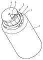
도 1 은 본 발명에 따른 클로저를 통하여 밀봉되는 용기의 경사도를 나타낸다.
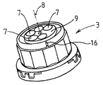
도 2 는 다수의 제거 개구를 갖는 클로저 캡의 경사도를 나타낸다.
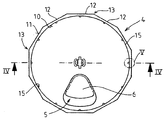
도 3 은 보호 캡의 확대 평면도를 나타낸다.
도 4 는 도 3 에 나타낸 보호 캡의 라인 (Ⅳ-Ⅳ) 을 따른 단면도를 나타낸다.
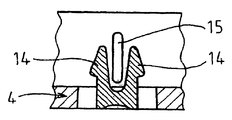
도 5 는 도 3 에 나타낸 보호 캡의 확대 단면 상세도 (Ⅴ) 를 나타낸다.
도 6 은 도 3 에 나타낸 보호 캡의 확대 상세도 (Ⅵ) 를 나타낸다.
도 7 은 클로저를 갖는 도 1 에 나타낸 용기의 라인 (Ⅶ-Ⅶ) 을 따른 부분 단면도이다.
도 8 은 도 2 에 나타낸 클로저 캡의 저면도이다. 1 shows the inclination of a container sealed through a closure according to the invention.
2 shows the inclination of the closure cap with multiple removal openings.
3 shows an enlarged plan view of the protective cap.
FIG. 4 shows a sectional view along the line IV-IV of the protective cap shown in FIG. 3.
FIG. 5 shows an enlarged cross-sectional detail view (V) of the protective cap shown in FIG. 3.
FIG. 6 shows an enlarged detail (VI) of the protective cap shown in FIG. 3.
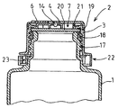
FIG. 7 is a partial cross-sectional view along the line VII-VII of the container shown in FIG. 1 with a closure. FIG.
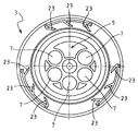
FIG. 8 is a bottom view of the closure cap shown in FIG. 2. FIG.
도 1 에 나타낸 용기 (1) 는 이 도면에는 보이지 않지만 클로저 (2) 에 의해 밀봉되는 개구를 갖는다. 클로저 (2) 는 클로저 캡 (3) 및 이 클로저 캡 (3) 에 회전 가능하게 배치된 보호 캡 (4) 을 갖는다. 보호 캡 (4) 은 컷 아웃 (5) 을 가지며, 이 컷 아웃은 완전히 채워진 용기 (1) 의 전달 상태에서 안전 커버 (6) 에 의해 완전하게 커버된다. 용기 (1) 에 있는 무균의 또는 수분 민감성 매질을 최초로 제거할 수 있게 하기 위해, 안전 커버 (6) 는 보호 캡 (4) 으로부터 분리되어야만 하며, 따라서 이 보호 캡 아래에 있는 컷 아웃 (5) 은 외부로부터 접근할 수 있게 되고 매질의 제거를 용이하게 한다. The container 1 shown in FIG. 1 has an opening which is not shown in this figure but is sealed by the
이를 위해, 도 2 에 개별적으로 나타낸 클로저 캡 (3) 은 다수의 제거 개구 (7) 를 갖는다. 도면에 나타낸 예시적인 실시형태에서, 5 개의 원형 제거 개구 (7) 가 서로로부터 그리고 클로저 캡 (3) 의 회전 축선 (8) 으로부터 어떠한 간격으로 배치된다. 제거 개구 (7) 에 둘러싸이지 않고 그 치수가 각각의 제거 개구 (7) 의 치수보다 더 큰 구역 (9) 이 두 인접한 제거 개구 (7) 사이에 배치된다. 이 구역 (9) 에서, 클로저 캡 (3) 은, 보호 캡 (4) 의 특정 배열과 상관없이, 기본적으로는 용기 (1) 의 개구의 할당 영역을 커버한다. For this purpose, the
예시를 위해, 도 3 및 도 4 는 보호 캡 (4) 의 확대도를 나타낸다. 보호 캡 (4) 의 컷 아웃 (5) 은 안전 커버 (6) 에 의해 대부분 커버되어 있고, 안전 커버는 보호 캡 (4) 위에 일체로 형성되고 좁은 웹 (web) 을 통해 보호 캡 (4) 에 연결된다. 이러한 방법으로 디자인 된 보호 캡 (4) 은 예컨대 폴리에틸렌 (PE) 과 같은 적절한 재료로부터, 표준 사출 성형 공정을 사용하여 간단하고 저렴하게 생산될 수 있다. 3 and 4 show an enlarged view of the
보호 캡 (4) 은 본질적으로는 원통형 내면 (10) 및 보호 캡 (4) 의 둘레를 따라 12 개의 편평한 면 (12) 으로 나누어지는 외면 (11) 을 갖는다. 편평한 면 (12) 은 각각 인접한 편평한 면 (12) 에 대해 30°의 각을 갖는다. 이러한 방법으로 형성된 에지 (13) 는 보호 캡 (4) 이 간단하게 파지되고 회전될 수 있게 하는, 간단한 한 손 조작 (one-handed operation) 을 가능하게 한다. The
보호 캡 (4) 은 그의 중심에 두 개의 래치 요소 (14) 를 가지며, 이들은 클로저 캡 (3) 의 할당 개구 안으로 유입될 수 있고 보호 캡 (4) 을 클로저 캡 (3) 에 영구적으로 연결시킬 수 있다. 보호 캡 (4) 이 클로저 캡 (3) 으로부터 분리되어야 한다면, 두 개의 래치 요소 (14) 중 적어도 하나는 이를 위해 구부러지거나 또는 벌어져야만 하며, 이는 최초의 클로저 캡 (3) 으로부터 보호 캡 (4) 의 완전한 분리가 어느 때에도 분명히 알 수 있다는 것을 의미한다. 이는 또한 쉽게 조작할 수 없는 보호 수단을 나타낸다. 예시적인 실시형태에서 실현되는, 래치 요소 (14) 의 하나의 가능한 디자인은 도 6 에 더 확대되어 나타나 있다. The
클로저 캡 (3) 에 대하여 보호 캡 (4) 의 배열을 간소화 또는 명시하기 위해, 보호 캡 (4) 은 내면 (10) 에 다수의, 나타낸 예시적인 실시형태에는 12 개인, 내부로 돌출하는 비드형 래치 요소 (15) 를 갖는다. 래치 요소 (15) 는 각각 편평한 면 (12) 에 할당될 수 있다. 클로저 캡 (3) 은 래치 요소 (15) 의 형상에 매치되고 둘레 방향으로 수직으로 배열되는 홈 (16) 을 갖고, 이 홈 안에 래치 요소 (15) 가 각각 결합될 수 있다. 홈 (16) 은, 예컨대 도 2 에 나타나 있다. In order to simplify or specify the arrangement of the
래치 요소 (15) 의 형상은, 한편 보호 캡 (4) 의 회전이 과도하게 방지되지 않도록 하면서, 다른 한편, 클로저 캡 (3) 의 홈 (16) 에 결합되는 래치 요소 (15) 에 의한 보호 캡 (4) 의 위치 지정이 바람직하게 되는 형상이다. 따라서 사용자가 보호 캡 (4) 의 회전에서, 래치 요소 (15) 에 의해 명시되는 보호 캡 (4) 의 위치 및 클로저 캡 (3) 에 대한 컷 아웃 (5) 의 위치를 감지 또는 느낄 수 있다. The shape of the
래치 요소 (15) 의 가능한 디자인이 도 5 의 확대 상세도에 예시되어 있다. A possible design of the
도 7 은 용기 (1) 의 단면도를 나타내며, 이 용기는 그의 전달 상태에서, 클로저 (2) 를 통하여 밀봉된다. 클로저 (2) 의 클로저 캡 (3) 은 나사산 (17) 을 통하여 용기 (1) 에 조여진다. 격막 (20) 이 용기의 상부 에지 (18) 와 클로저 캡 (3) 의 내측 (19) 사이에 배치된다. 격막 (20) 은 바람직하게는 용기 (1) 의 내부를 향하는 면이, 예컨대 PTFE 와 같은 불활성 재료로 코팅된 실리콘으로 이루어진다. 7 shows a cross-sectional view of the container 1, which, in its delivery state, is sealed through the
격막 (20) 을 향하는 내측 (19) 에서, 클로저 캡 (3) 은 외부 에지로부터 어떠한 간격으로 배치되고, 용기의 내부의 방향으로 돌출하는 형상부 (21) 를 갖는다. 클로저 캡 (3) 이 용기 (1) 에 단단하게 조여질 때, 내부로 돌출하는 형상부 (21) 는 용기 (1) 의 상부 에지 (18) 내측의 격막 (20) 위에 눌리고 격막의 미세한 변형을 발생시키며, 따라서 격막 (20) 의 재료는 장력을 받고 재료의 자기 밀봉 특성은 증가된다. On the
용기 (1) 에 대한 클로저 캡 (3) 의 조임 클로저에는 또한 쉽게 조작할 수 없는 보호 수단이 제공된다. 이를 위해, 방사상으로 내부로 배열되지 않지만, 대신 각각 약 50°의 각을 갖는 다수의 층상 (lamellar) 형상부 (23) 가 용기 (1) 를 향하는 클로저 캡 (3) 의 단부 영역 (22) 에 형성된다. 용기 (1) 는 어떠한 각도로 돌출하는 매치되는 형상부를 갖고, 이는 클로저 캡 (3) 이 용기 (1) 에 조여질 때 형상부 (23) 가 용기 (1) 의 형상에 걸쳐 사실상 제약을 받지 않고 미끄러지도록 디자인되고, 반면 클로저 캡 (3) 을 해제하기 위하여 클로저 캡 (3) 이 풀리고 증가된 작용력에 의해 구부러져야 할 때 형상부 (23) 는 용기 (1) 의 관련 형상부와 결합된다. 이러한 방법으로, 필요하다면 또는 개별적인 경우에 요구된다면 용기 개구를 완전히 개방시키기 위해 클로저 (2) 는 용기 (1) 로부터 완전히 제거될 수 있다. 하지만, 이러한 방식으로 용기 (1) 를 개방하는 것은 이후 어느 때에도 분명히 알 수 있는 층상 형상부 (23) 의 영구적인 변형을 야기하며, 또한 쉽게 조작할 수 없는 보호 수단을 제공한다. The tightening closure of the
클로저 (2) 는 어떠한 사출 성형 가능한 폴리머를 사용하여 생산될 수 있지만, 이러한 폴리머는 바람직하게는 공격성 용매 (aggressive solvent) 에 대하여 불활성이며, 또한 침출 (leaching) 에 대해서도 불활성이다. The
클로저 캡 (3) 에 대한 보호 캡 (4) 의 한 방향의 회전이 미리 명시되는 것이 또한 있을 수 있다. 이를 위해, 비교 가능한 층상 형상부 (23) 는 예를 들어, 보호 캡 (4) 또는 클로저 캡 (3) 에 제공될 수 있고 이 형상부는 예컨대 보호 캡 (4) 의 한 방향의 회전만이 가능하게 하고 반대 방향의 회전을 막는다. 이러한 방법으로, 보호 캡 (4) 이 상이한 방향으로 다회 회전되는 것과 컷 아웃 (5) 이 매질의 제거를 위해 이미 사용된 제거 개구 (7) 에 걸쳐 반복적으로 위치되는 것을 방지하는 것이 가능하다. 이러한 종류의 조치를 통하여, 용기 (1) 에 있는 매질의 무균성은 또한 다수의 제거 조작에 대하여 실질적으로 보장될 수 있다. It may also be that the rotation of one direction of the
도면에 나타낸 예시적인 실시형태는 단지 예시를 위한 것이며 당업자에게 이용될 수 있는 지식의 범위 내에서 다양한 변경이 가능하다. 하지만, 설명된 발명의 원리의 일반적 유효성 때문에, 실시예로서 나타낸 예시적인 실시형태는 본 출원의 보호 범위를 이 실시형태로 줄이는 것은 적절하지 않다. The illustrative embodiments shown in the figures are for illustration only and various modifications are possible within the scope of knowledge available to those skilled in the art. However, because of the general effectiveness of the principles of the described invention, the exemplary embodiments shown as examples are not appropriate to reduce the protection scope of the present application to this embodiment.
본 발명에 본질적인 특징으로서 특별히 나타내지 않는다면, 도면에 나타낸 또는 설명된 치수 또는 상대 크기 비율은 단지 각각의 경우 본 발명의 원리의 가능한 실시형태를 예시하기 위한 것임은 당업자에게 말할 필요도 없으며, 따라서 이러한 치수 또는 크기 비율에 구속되지 않는다. Unless specifically indicated as an essential feature of the invention, it is needless to say to those skilled in the art that the dimensions or relative size ratios shown or described in the drawings are only intended to illustrate possible embodiments of the principles of the invention in each case. Or is not bound to size ratio.
Claims (8)
Applications Claiming Priority (4)
| Application Number | Priority Date | Filing Date | Title |
|---|---|---|---|
| DE102007030352.3 | 2007-06-29 | ||
| DE102007030352 | 2007-06-29 | ||
| DE102007058349.6 | 2007-12-03 | ||
| DE102007058349A DE102007058349A1 (en) | 2007-06-29 | 2007-12-03 | shutter |
Related Child Applications (1)
| Application Number | Title | Priority Date | Filing Date |
|---|---|---|---|
| KR20157005258A Division KR20150034810A (en) | 2007-06-29 | 2008-06-02 | Closure with membrane and rotatable protective cap |
Publications (2)
| Publication Number | Publication Date |
|---|---|
| KR20100040887A true KR20100040887A (en) | 2010-04-21 |
| KR101603348B1 KR101603348B1 (en) | 2016-03-14 |
Family
ID=40076110
Family Applications (2)
| Application Number | Title | Priority Date | Filing Date |
|---|---|---|---|
| KR1020107001876A Expired - Fee Related KR101603348B1 (en) | 2007-06-29 | 2008-06-02 | Closure with membrane and rotatable protective cap |
| KR20157005258A Ceased KR20150034810A (en) | 2007-06-29 | 2008-06-02 | Closure with membrane and rotatable protective cap |
Family Applications After (1)
| Application Number | Title | Priority Date | Filing Date |
|---|---|---|---|
| KR20157005258A Ceased KR20150034810A (en) | 2007-06-29 | 2008-06-02 | Closure with membrane and rotatable protective cap |
Country Status (12)
| Country | Link |
|---|---|
| US (1) | US10160576B2 (en) |
| EP (1) | EP2160337B1 (en) |
| JP (1) | JP5319669B2 (en) |
| KR (2) | KR101603348B1 (en) |
| CN (1) | CN101687581B (en) |
| AT (1) | ATE526249T1 (en) |
| AU (1) | AU2008271686B2 (en) |
| BR (1) | BRPI0813466B1 (en) |
| DE (1) | DE102007058349A1 (en) |
| ES (1) | ES2373868T3 (en) |
| NZ (1) | NZ582880A (en) |
| WO (1) | WO2009003563A1 (en) |
Families Citing this family (18)
| Publication number | Priority date | Publication date | Assignee | Title |
|---|---|---|---|---|
| DE102007058349A1 (en) * | 2007-06-29 | 2009-01-02 | Merck Patent Gmbh | shutter |
| US20090166311A1 (en) * | 2007-12-27 | 2009-07-02 | Helvoet Pharma Belgium N.V. | Pharmaceutical closure with a laser-applied marking |
| US9668939B2 (en) | 2012-02-02 | 2017-06-06 | Becton Dickinson Holdings Pte. Ltd. | Adaptor for coupling with a medical container |
| SG192310A1 (en) | 2012-02-02 | 2013-08-30 | Becton Dickinson Holdings Pte Ltd | Adaptor for coupling to a medical container |
| SG192312A1 (en) * | 2012-02-02 | 2013-08-30 | Becton Dickinson Holdings Pte Ltd | Adaptor for coupling to a medical container |
| EP2735300A1 (en) * | 2012-11-26 | 2014-05-28 | Becton Dickinson France | Adaptor for multidose medical container |
| CN103057830B (en) * | 2013-01-21 | 2015-04-15 | 浙江欧诗漫集团有限公司 | Cosmetic tube |
| JP1526207S (en) | 2013-08-05 | 2015-06-15 | ||
| DE202013012012U1 (en) | 2013-12-20 | 2014-12-22 | Leica Biosystems Nussloch Gmbh | Self-sealing connection system and connecting element |
| CN111465681B (en) * | 2017-12-21 | 2024-04-05 | 环球生命科技咨询美国有限责任公司 | Fluid port |
| GB2610544B (en) * | 2018-11-17 | 2023-07-05 | Ceres Chill Co | Vessel for breast milk collection, preservation, transportation, and delivery |
| USD920803S1 (en) | 2019-10-23 | 2021-06-01 | S. C. Johnson & Son, Inc. | Dispenser |
| US12397975B2 (en) | 2021-01-27 | 2025-08-26 | Gill, Llc | Multi-component sample container cap |
| DE102021106715A1 (en) | 2021-03-18 | 2022-09-22 | G.A.S. Gesellschaft für analytische Sensorsysteme m.b.H. | locking attachment |
| USD980074S1 (en) | 2021-07-13 | 2023-03-07 | S. C. Johnson & Son, Inc. | Container |
| US11975895B2 (en) * | 2021-10-06 | 2024-05-07 | Sysler Corporation | Multi-purpose container |
| US12595098B2 (en) | 2022-04-01 | 2026-04-07 | Sarvjit Gill | Fluid sample container cap |
| CA3247325A1 (en) * | 2022-04-01 | 2023-10-05 | Gill, Llc | Locking sample cap |
Citations (2)
| Publication number | Priority date | Publication date | Assignee | Title |
|---|---|---|---|---|
| US1189465A (en) * | 1916-01-24 | 1916-07-04 | Abbott Lab | Container for hypodermic solutions. |
| US6988642B2 (en) * | 2002-10-29 | 2006-01-24 | Johnson & Johnson Consumer Companies | Tamper-evident dispenser bottle |
Family Cites Families (33)
| Publication number | Priority date | Publication date | Assignee | Title |
|---|---|---|---|---|
| DE220068C (en) | ||||
| US2183585A (en) * | 1939-12-19 | Container | ||
| US2142278A (en) * | 1938-07-23 | 1939-01-03 | Ralph W Mendelson | Medicinal carrying tube |
| US2459304A (en) * | 1946-08-28 | 1949-01-18 | Blank Frederick | Medical vial stopper for insuring sterile needle punctures |
| US2608972A (en) * | 1948-02-23 | 1952-09-02 | Chrigstrom Knut Vilhelm | Guide for hypodermic syringes |
| US2629379A (en) * | 1951-02-21 | 1953-02-24 | Abbott Lab | Puncture indicating closure for multiple dose vials |
| US3209964A (en) * | 1963-09-30 | 1965-10-05 | Johnson & Johnson | Dispenser-container |
| NL275977A (en) * | 1963-11-22 | |||
| US3260422A (en) * | 1964-07-27 | 1966-07-12 | Owens Illinois Glass Co | Shaker or sifter-type dispensers |
| US3260423A (en) * | 1964-07-27 | 1966-07-12 | Owens Illinois Inc | Shaker or sifter-type dispensers |
| US3260426A (en) * | 1964-10-13 | 1966-07-12 | Wheaton Plastics Company | Container closure comprising a stationary apertured cap and a rotary apertured cap |
| US3325066A (en) * | 1965-10-22 | 1967-06-13 | Continental Can Co | Dispensing container having a rotary closure cap |
| US3424329A (en) * | 1967-06-21 | 1969-01-28 | Schering Corp | Sealed injection vial |
| US3855997A (en) * | 1973-07-11 | 1974-12-24 | Cinco Medical Health Supply Co | Sterile specimen trap |
| US4076152A (en) * | 1977-05-23 | 1978-02-28 | Owens-Illinois, Inc. | Fitment-retaining closure |
| US4254884A (en) * | 1978-10-20 | 1981-03-10 | Toppan Printing Co., Ltd. | Plug body for a container |
| FR2460261A1 (en) * | 1979-07-04 | 1981-01-23 | Tournus Sa Moulage | SAFETY BUMPER STOPPER |
| US4437593A (en) * | 1982-07-12 | 1984-03-20 | Three Sisters Ranch Enterprises | Overcap for spice canister |
| US4613063A (en) * | 1985-01-07 | 1986-09-23 | Sunbeam Plastics Corporation | Dispensing package |
| US4934546A (en) * | 1989-01-30 | 1990-06-19 | Cap Snap Co. | Tamper evident cap having lift tab on bottom edge |
| US4984700A (en) * | 1989-11-17 | 1991-01-15 | Calmar, Inc. | Tamper indicating closure assembly |
| US5183171A (en) * | 1991-08-23 | 1993-02-02 | J. L. Clark, Inc. | Closure with dispensing fitment and screw-on cap |
| US5269432A (en) * | 1993-04-19 | 1993-12-14 | Beckertgis Nicholas G | Insect-proof and tamper-evident cover for beverage container |
| US5388731A (en) * | 1993-05-04 | 1995-02-14 | Continental Plastics, Inc. | Cap and dispensing fitment combination wherein the cap has retaining means engaging the fitment |
| US5680968A (en) * | 1995-05-03 | 1997-10-28 | Phoenix Closures, Inc. | Container closure system |
| IT1287402B1 (en) * | 1996-02-29 | 1998-08-06 | Bormioli Metalplast Spa | CAPSULE FOR THE SAFETY CLOSURE OF CONTAINERS |
| EP0909719B1 (en) * | 1997-10-15 | 2002-07-24 | Taisei Kako Co., Ltd., | Closure for vial container |
| CN2387054Y (en) * | 1999-08-19 | 2000-07-12 | 徐明堂 | Metal can |
| DE10138191B4 (en) * | 2001-08-03 | 2004-02-26 | Helvoet Pharma Belgium N.V. | Cap for infusion or transfusion bottles |
| US7438204B2 (en) * | 2005-10-13 | 2008-10-21 | S. C. Johnson & Son, Inc. | Apparatus for dispensing a granular product from a container |
| US7766197B2 (en) * | 2006-02-28 | 2010-08-03 | Silgan Plastics Corporation | Closure with selectable dispensing orifices |
| US7513399B2 (en) * | 2006-02-28 | 2009-04-07 | Silgan Plastics Corporation | Closure with selectable dispensing orifices |
| DE102007058349A1 (en) * | 2007-06-29 | 2009-01-02 | Merck Patent Gmbh | shutter |
-
2007
- 2007-12-03 DE DE102007058349A patent/DE102007058349A1/en not_active Withdrawn
-
2008
- 2008-06-02 EP EP08758932A patent/EP2160337B1/en active Active
- 2008-06-02 CN CN2008800227272A patent/CN101687581B/en active Active
- 2008-06-02 AT AT08758932T patent/ATE526249T1/en active
- 2008-06-02 KR KR1020107001876A patent/KR101603348B1/en not_active Expired - Fee Related
- 2008-06-02 US US12/666,967 patent/US10160576B2/en active Active
- 2008-06-02 KR KR20157005258A patent/KR20150034810A/en not_active Ceased
- 2008-06-02 WO PCT/EP2008/004363 patent/WO2009003563A1/en not_active Ceased
- 2008-06-02 JP JP2010513697A patent/JP5319669B2/en not_active Expired - Fee Related
- 2008-06-02 AU AU2008271686A patent/AU2008271686B2/en not_active Ceased
- 2008-06-02 ES ES08758932T patent/ES2373868T3/en active Active
- 2008-06-02 BR BRPI0813466-9A patent/BRPI0813466B1/en not_active IP Right Cessation
- 2008-06-02 NZ NZ582880A patent/NZ582880A/en not_active IP Right Cessation
Patent Citations (2)
| Publication number | Priority date | Publication date | Assignee | Title |
|---|---|---|---|---|
| US1189465A (en) * | 1916-01-24 | 1916-07-04 | Abbott Lab | Container for hypodermic solutions. |
| US6988642B2 (en) * | 2002-10-29 | 2006-01-24 | Johnson & Johnson Consumer Companies | Tamper-evident dispenser bottle |
Also Published As
| Publication number | Publication date |
|---|---|
| DE102007058349A1 (en) | 2009-01-02 |
| BRPI0813466A2 (en) | 2015-01-06 |
| ATE526249T1 (en) | 2011-10-15 |
| JP5319669B2 (en) | 2013-10-16 |
| EP2160337B1 (en) | 2011-09-28 |
| AU2008271686B2 (en) | 2013-09-12 |
| ES2373868T3 (en) | 2012-02-09 |
| EP2160337A1 (en) | 2010-03-10 |
| US10160576B2 (en) | 2018-12-25 |
| CN101687581B (en) | 2012-02-22 |
| JP2010531781A (en) | 2010-09-30 |
| KR101603348B1 (en) | 2016-03-14 |
| US20100176080A1 (en) | 2010-07-15 |
| AU2008271686A1 (en) | 2009-01-08 |
| KR20150034810A (en) | 2015-04-03 |
| CN101687581A (en) | 2010-03-31 |
| WO2009003563A1 (en) | 2009-01-08 |
| BRPI0813466B1 (en) | 2018-04-03 |
| NZ582880A (en) | 2011-08-26 |
Similar Documents
| Publication | Publication Date | Title |
|---|---|---|
| KR20100040887A (en) | Closure with membrane and rotatable protective cap | |
| US8678222B2 (en) | Airtight compact | |
| US7690525B2 (en) | Screw cap | |
| EP1435254B1 (en) | Tube closure with removable septum | |
| US4362250A (en) | Container for storing reactive or volatile material | |
| CN109896149A (en) | Closures, Liquid Containment Systems and Fluid Storage Kits for Fluid Containers | |
| EP1638856A1 (en) | Flip top container with built in desiccant | |
| WO2018230307A1 (en) | Volatilization container | |
| KR102074579B1 (en) | Mask pack case | |
| CN103298710B (en) | Duplex container | |
| CA1058566A (en) | Specimen container | |
| CN210192258U (en) | Children lock box | |
| SE509830C2 (en) | Containers for storage of tablets | |
| JPH04267773A (en) | Dispensation and storage container | |
| KR20100004811U (en) | Cosmetic vessel with an airtight sealed structure | |
| JP2000226054A (en) | Sealed container with virgin seal | |
| CN109562873A (en) | The method of container including accommodation space and the accommodation space h substance from container | |
| US11655079B1 (en) | Anti-theft plastic bottle cap | |
| KR100626872B1 (en) | Stopper structure of the container which is built in the elastic brace | |
| KR102616502B1 (en) | Hermetically sealed container assembly with enhanced tightness and bondability | |
| KR101262072B1 (en) | Screw cap package for contact lens | |
| CA2240928C (en) | Container for storing tablets | |
| KR200221814Y1 (en) | Cap for vessel | |
| KR200340196Y1 (en) | Container plug having a silica packing | |
| JP2005178867A (en) | Tamper-evident hinge cap |
Legal Events
| Date | Code | Title | Description |
|---|---|---|---|
| PA0105 | International application |
St.27 status event code: A-0-1-A10-A15-nap-PA0105 |
|
| P11-X000 | Amendment of application requested |
St.27 status event code: A-2-2-P10-P11-nap-X000 |
|
| P13-X000 | Application amended |
St.27 status event code: A-2-2-P10-P13-nap-X000 |
|
| PG1501 | Laying open of application |
St.27 status event code: A-1-1-Q10-Q12-nap-PG1501 |
|
| A201 | Request for examination | ||
| P11-X000 | Amendment of application requested |
St.27 status event code: A-2-2-P10-P11-nap-X000 |
|
| P13-X000 | Application amended |
St.27 status event code: A-2-2-P10-P13-nap-X000 |
|
| PA0201 | Request for examination |
St.27 status event code: A-1-2-D10-D11-exm-PA0201 |
|
| E902 | Notification of reason for refusal | ||
| PE0902 | Notice of grounds for rejection |
St.27 status event code: A-1-2-D10-D21-exm-PE0902 |
|
| P11-X000 | Amendment of application requested |
St.27 status event code: A-2-2-P10-P11-nap-X000 |
|
| P13-X000 | Application amended |
St.27 status event code: A-2-2-P10-P13-nap-X000 |
|
| E601 | Decision to refuse application | ||
| PE0601 | Decision on rejection of patent |
St.27 status event code: N-2-6-B10-B15-exm-PE0601 |
|
| PJ0201 | Trial against decision of rejection |
St.27 status event code: A-3-3-V10-V11-apl-PJ0201 |
|
| A107 | Divisional application of patent | ||
| PA0104 | Divisional application for international application |
St.27 status event code: A-0-1-A10-A18-div-PA0104 St.27 status event code: A-0-1-A10-A16-div-PA0104 |
|
| J301 | Trial decision |
Free format text: TRIAL DECISION FOR APPEAL AGAINST DECISION TO DECLINE REFUSAL REQUESTED 20150128 Effective date: 20151123 |
|
| PJ1301 | Trial decision |
St.27 status event code: A-3-3-V10-V15-crt-PJ1301 Decision date: 20151123 Appeal event data comment text: Appeal Kind Category : Appeal against decision to decline refusal, Appeal Ground Text : 2010 7001876 Appeal request date: 20150128 Appellate body name: Patent Examination Board Decision authority category: Office appeal board Decision identifier: 2015101000451 |
|
| PS0901 | Examination by remand of revocation |
St.27 status event code: A-6-3-E10-E12-rex-PS0901 |
|
| S901 | Examination by remand of revocation | ||
| GRNO | Decision to grant (after opposition) | ||
| PS0701 | Decision of registration after remand of revocation |
St.27 status event code: A-3-4-F10-F13-rex-PS0701 |
|
| GRNT | Written decision to grant | ||
| PR0701 | Registration of establishment |
St.27 status event code: A-2-4-F10-F11-exm-PR0701 |
|
| PR1002 | Payment of registration fee |
St.27 status event code: A-2-2-U10-U12-oth-PR1002 Fee payment year number: 1 |
|
| PG1601 | Publication of registration |
St.27 status event code: A-4-4-Q10-Q13-nap-PG1601 |
|
| FPAY | Annual fee payment |
Payment date: 20190218 Year of fee payment: 4 |
|
| PR1001 | Payment of annual fee |
St.27 status event code: A-4-4-U10-U11-oth-PR1001 Fee payment year number: 4 |
|
| FPAY | Annual fee payment |
Payment date: 20200218 Year of fee payment: 5 |
|
| PR1001 | Payment of annual fee |
St.27 status event code: A-4-4-U10-U11-oth-PR1001 Fee payment year number: 5 |
|
| PR1001 | Payment of annual fee |
St.27 status event code: A-4-4-U10-U11-oth-PR1001 Fee payment year number: 6 |
|
| R18-X000 | Changes to party contact information recorded |
St.27 status event code: A-5-5-R10-R18-oth-X000 |
|
| PR1001 | Payment of annual fee |
St.27 status event code: A-4-4-U10-U11-oth-PR1001 Fee payment year number: 7 |
|
| PR1001 | Payment of annual fee |
St.27 status event code: A-4-4-U10-U11-oth-PR1001 Fee payment year number: 8 |
|
| PR1001 | Payment of annual fee |
St.27 status event code: A-4-4-U10-U11-oth-PR1001 Fee payment year number: 9 |
|
| PC1903 | Unpaid annual fee |
St.27 status event code: A-4-4-U10-U13-oth-PC1903 Not in force date: 20250309 Payment event data comment text: Termination Category : DEFAULT_OF_REGISTRATION_FEE |
|
| H13 | Ip right lapsed |
Free format text: ST27 STATUS EVENT CODE: N-4-6-H10-H13-OTH-PC1903 (AS PROVIDED BY THE NATIONAL OFFICE); TERMINATION CATEGORY : DEFAULT_OF_REGISTRATION_FEE Effective date: 20250309 |
|
| PC1903 | Unpaid annual fee |
St.27 status event code: N-4-6-H10-H13-oth-PC1903 Ip right cessation event data comment text: Termination Category : DEFAULT_OF_REGISTRATION_FEE Not in force date: 20250309 |