KR20090063213A - Fuel cell assembly - Google Patents
Fuel cell assembly Download PDFInfo
- Publication number
- KR20090063213A KR20090063213A KR1020097004940A KR20097004940A KR20090063213A KR 20090063213 A KR20090063213 A KR 20090063213A KR 1020097004940 A KR1020097004940 A KR 1020097004940A KR 20097004940 A KR20097004940 A KR 20097004940A KR 20090063213 A KR20090063213 A KR 20090063213A
- Authority
- KR
- South Korea
- Prior art keywords
- face
- mea
- gas diffusion
- catalyst
- contact
- Prior art date
Links
Images


Classifications
-
- H—ELECTRICITY
- H01—ELECTRIC ELEMENTS
- H01M—PROCESSES OR MEANS, e.g. BATTERIES, FOR THE DIRECT CONVERSION OF CHEMICAL ENERGY INTO ELECTRICAL ENERGY
- H01M8/00—Fuel cells; Manufacture thereof
- H01M8/06—Combination of fuel cells with means for production of reactants or for treatment of residues
- H01M8/0606—Combination of fuel cells with means for production of reactants or for treatment of residues with means for production of gaseous reactants
- H01M8/065—Combination of fuel cells with means for production of reactants or for treatment of residues with means for production of gaseous reactants by dissolution of metals or alloys; by dehydriding metallic substances
-
- H—ELECTRICITY
- H01—ELECTRIC ELEMENTS
- H01M—PROCESSES OR MEANS, e.g. BATTERIES, FOR THE DIRECT CONVERSION OF CHEMICAL ENERGY INTO ELECTRICAL ENERGY
- H01M4/00—Electrodes
- H01M4/86—Inert electrodes with catalytic activity, e.g. for fuel cells
-
- H—ELECTRICITY
- H01—ELECTRIC ELEMENTS
- H01M—PROCESSES OR MEANS, e.g. BATTERIES, FOR THE DIRECT CONVERSION OF CHEMICAL ENERGY INTO ELECTRICAL ENERGY
- H01M4/00—Electrodes
- H01M4/86—Inert electrodes with catalytic activity, e.g. for fuel cells
- H01M4/8605—Porous electrodes
-
- H—ELECTRICITY
- H01—ELECTRIC ELEMENTS
- H01M—PROCESSES OR MEANS, e.g. BATTERIES, FOR THE DIRECT CONVERSION OF CHEMICAL ENERGY INTO ELECTRICAL ENERGY
- H01M8/00—Fuel cells; Manufacture thereof
- H01M8/02—Details
-
- H—ELECTRICITY
- H01—ELECTRIC ELEMENTS
- H01M—PROCESSES OR MEANS, e.g. BATTERIES, FOR THE DIRECT CONVERSION OF CHEMICAL ENERGY INTO ELECTRICAL ENERGY
- H01M8/00—Fuel cells; Manufacture thereof
- H01M8/02—Details
- H01M8/0202—Collectors; Separators, e.g. bipolar separators; Interconnectors
- H01M8/023—Porous and characterised by the material
- H01M8/0232—Metals or alloys
-
- H—ELECTRICITY
- H01—ELECTRIC ELEMENTS
- H01M—PROCESSES OR MEANS, e.g. BATTERIES, FOR THE DIRECT CONVERSION OF CHEMICAL ENERGY INTO ELECTRICAL ENERGY
- H01M8/00—Fuel cells; Manufacture thereof
- H01M8/02—Details
- H01M8/0202—Collectors; Separators, e.g. bipolar separators; Interconnectors
- H01M8/023—Porous and characterised by the material
- H01M8/0234—Carbonaceous material
-
- H—ELECTRICITY
- H01—ELECTRIC ELEMENTS
- H01M—PROCESSES OR MEANS, e.g. BATTERIES, FOR THE DIRECT CONVERSION OF CHEMICAL ENERGY INTO ELECTRICAL ENERGY
- H01M8/00—Fuel cells; Manufacture thereof
- H01M8/02—Details
- H01M8/0202—Collectors; Separators, e.g. bipolar separators; Interconnectors
- H01M8/0247—Collectors; Separators, e.g. bipolar separators; Interconnectors characterised by the form
- H01M8/0252—Collectors; Separators, e.g. bipolar separators; Interconnectors characterised by the form tubular
-
- H—ELECTRICITY
- H01—ELECTRIC ELEMENTS
- H01M—PROCESSES OR MEANS, e.g. BATTERIES, FOR THE DIRECT CONVERSION OF CHEMICAL ENERGY INTO ELECTRICAL ENERGY
- H01M8/00—Fuel cells; Manufacture thereof
- H01M8/10—Fuel cells with solid electrolytes
- H01M8/1004—Fuel cells with solid electrolytes characterised by membrane-electrode assemblies [MEA]
-
- H—ELECTRICITY
- H01—ELECTRIC ELEMENTS
- H01M—PROCESSES OR MEANS, e.g. BATTERIES, FOR THE DIRECT CONVERSION OF CHEMICAL ENERGY INTO ELECTRICAL ENERGY
- H01M8/00—Fuel cells; Manufacture thereof
- H01M8/10—Fuel cells with solid electrolytes
- H01M8/1009—Fuel cells with solid electrolytes with one of the reactants being liquid, solid or liquid-charged
- H01M8/1011—Direct alcohol fuel cells [DAFC], e.g. direct methanol fuel cells [DMFC]
-
- H—ELECTRICITY
- H01—ELECTRIC ELEMENTS
- H01M—PROCESSES OR MEANS, e.g. BATTERIES, FOR THE DIRECT CONVERSION OF CHEMICAL ENERGY INTO ELECTRICAL ENERGY
- H01M8/00—Fuel cells; Manufacture thereof
- H01M8/10—Fuel cells with solid electrolytes
- H01M2008/1095—Fuel cells with polymeric electrolytes
-
- H—ELECTRICITY
- H01—ELECTRIC ELEMENTS
- H01M—PROCESSES OR MEANS, e.g. BATTERIES, FOR THE DIRECT CONVERSION OF CHEMICAL ENERGY INTO ELECTRICAL ENERGY
- H01M8/00—Fuel cells; Manufacture thereof
- H01M8/02—Details
- H01M8/0202—Collectors; Separators, e.g. bipolar separators; Interconnectors
- H01M8/0258—Collectors; Separators, e.g. bipolar separators; Interconnectors characterised by the configuration of channels, e.g. by the flow field of the reactant or coolant
- H01M8/026—Collectors; Separators, e.g. bipolar separators; Interconnectors characterised by the configuration of channels, e.g. by the flow field of the reactant or coolant characterised by grooves, e.g. their pitch or depth
-
- H—ELECTRICITY
- H01—ELECTRIC ELEMENTS
- H01M—PROCESSES OR MEANS, e.g. BATTERIES, FOR THE DIRECT CONVERSION OF CHEMICAL ENERGY INTO ELECTRICAL ENERGY
- H01M8/00—Fuel cells; Manufacture thereof
- H01M8/02—Details
- H01M8/0289—Means for holding the electrolyte
-
- Y—GENERAL TAGGING OF NEW TECHNOLOGICAL DEVELOPMENTS; GENERAL TAGGING OF CROSS-SECTIONAL TECHNOLOGIES SPANNING OVER SEVERAL SECTIONS OF THE IPC; TECHNICAL SUBJECTS COVERED BY FORMER USPC CROSS-REFERENCE ART COLLECTIONS [XRACs] AND DIGESTS
- Y02—TECHNOLOGIES OR APPLICATIONS FOR MITIGATION OR ADAPTATION AGAINST CLIMATE CHANGE
- Y02E—REDUCTION OF GREENHOUSE GAS [GHG] EMISSIONS, RELATED TO ENERGY GENERATION, TRANSMISSION OR DISTRIBUTION
- Y02E60/00—Enabling technologies; Technologies with a potential or indirect contribution to GHG emissions mitigation
- Y02E60/30—Hydrogen technology
- Y02E60/50—Fuel cells
Abstract
Description
본 발명은 연료 전지에 사용하기 위한 어셈블리, 특히 독특한 구성의 막전극 어셈블리에 관한 것이다.The present invention relates to assemblies for use in fuel cells, in particular membrane electrode assemblies of unique construction.
연료 전지는 전해질에 의해 분리된 2개의 촉매화 전극을 포함하는 전기화학 전지이다. 연료, 특히 수소(수소-함유 "리포메이트" 포함) 또는 메탄올이 애노드에 공급되고, 산화제, 예를 들어 산소 또는 공기가 캐소드에 공급된다. 전기화학 반응이 전극에서 일어나고, 연료 및 산화제의 화학 에너지가 전기 에너지 및 열로 전환된다. 연료 전지는 청정하고 효율적인 전력원이며, 고정 시설 및 자동차에서 내연 기관 (기체 터빈 포함)과 같은 통상의 동력원 또는 휴대용 전력 소모 장치에서 에너지 저장 배터리를 대체할 수 있다. 제 1 대형 연료 전지 스택 용품은 현재 하이엔드 보트 및 휴양용 차량을 위한 보조 전력원으로 시판되고 있다. 연료 전지에 대한 광범위한 연구가 계속되고 있고, 연료 전지는 랩탑 유형 컴퓨터, 휴대전화 및 유사한 소형 전자 제품에서 증가된 에너지 밀도 전력원을 제공할 배터리 교체물로서 논의되고 있다.The fuel cell is an electrochemical cell comprising two catalyzed electrodes separated by an electrolyte. Fuel, in particular hydrogen (including hydrogen-containing “lipomate”) or methanol, is supplied to the anode and an oxidant such as oxygen or air is supplied to the cathode. An electrochemical reaction takes place at the electrode and the chemical energy of the fuel and oxidant is converted into electrical energy and heat. Fuel cells are a clean and efficient power source and can replace energy storage batteries in conventional power sources such as internal combustion engines (including gas turbines) or portable power consumption devices in fixed installations and automobiles. The first large fuel cell stack article is currently commercially available as an auxiliary power source for high end boats and recreational vehicles. Extensive research continues on fuel cells, and fuel cells are being discussed as battery replacements that will provide increased energy density power sources in laptop type computers, mobile phones and similar small electronics.
연료전지의 주요 유형은 중합체 전해질 막(PEM) 전지이다. 여기서 전해질은 전기 절연성이지만 이온 전도성인 고체 중합체 막이다. 퍼플루오로설폰산 재료를 기재로 하는 프로톤-전도성 막이 통상 사용되지만, 많은 다른 막들이 연구되고 있다. 애노드에서 생성된 프로톤은 막을 통과하여 캐소드로 전달되고, 여기서 산소와 결합하여 물을 생성한다.The main type of fuel cell is a polymer electrolyte membrane (PEM) cell. The electrolyte here is a solid polymer membrane that is electrically insulating but ionically conductive. Although proton-conductive membranes based on perfluorosulfonic acid materials are commonly used, many other membranes have been studied. Protons produced at the anode pass through the membrane to the cathode where it combines with oxygen to produce water.
PEM 연료 전지의 주요 구성요소는 막 전극 어셈블리(MEA)이고, 최신 MEA는 5층을 갖는다. 중앙 층은 중합체 막이고, 애노드 및 캐소드에서 상이한 요건을 만족시키도록 설계된 전기 촉매층이 양면에 있다. 마지막으로, 기체 확산 기판이 각 촉매층에 인접한다. 기체 확산 기판은 반응물이 전기촉매층에 도달하도록 허용해야 하며, 또한 전기화학 반응에 의해 발생하는 전류를 전도해야 한다. 따라서, 기판은 다공성이어야 하고, 전기 전도성이어야 한다. 이 구성요소들을 서로 결합하고 밀봉하여, 연료 및 산화제 기체를 분배하고 물을 제거하는 강성 유동장 플레이트(rigid flow field plate)와 함께 완전한 전지로 구성되는 MEA를 형성한다. MEA 및 이와 결합된 유동장 플레이트를 포함하는 다수의 전지를 함께 조립하여 연료 전지 스택을 형성한다.The main component of the PEM fuel cell is the membrane electrode assembly (MEA), the latest MEA having five layers. The central layer is a polymer membrane, with electrocatalyst layers on both sides designed to meet different requirements at the anode and cathode. Finally, a gas diffusion substrate is adjacent to each catalyst layer. The gas diffusion substrate must allow the reactants to reach the electrocatalyst layer and also conduct the current generated by the electrochemical reaction. Thus, the substrate must be porous and electrically conductive. These components are combined and sealed together to form a complete cell MEA with a rigid flow field plate that distributes fuel and oxidant gas and removes water. A plurality of cells, including the MEA and flow field plates associated therewith, are assembled together to form a fuel cell stack.
MEA는 당업계에 공지된 여러 방법으로 조립할 수 있다. 전기촉매 ("촉매")층을 기체 확산 기판에 적용하여 기체 확산 전극을 형성할 수 있다. 이러한 두 전극을 막의 양면에 위치시켜 함께 적층시킬 수 있다. 다른 방법은 막의 양면에 두 촉매를 코팅하여 촉매-코팅막(CCM)을 형성하고, 기체 확산 기판을 촉매-코팅막의 양면에 적용한 후 적층시키는 것이다. 추가 방법은 막의 한면은 촉매로 코팅되고 기체 확산 기판을 가지며 막의 다른 면은 기체 확산 전극을 갖는 막을 사용하는 조합 방법이다.The MEA can be assembled by several methods known in the art. An electrocatalyst (“catalyst”) layer may be applied to the gas diffusion substrate to form a gas diffusion electrode. These two electrodes can be placed on both sides of the film and stacked together. Another method is to coat the two catalysts on both sides of the membrane to form a catalyst-coated membrane (CCM), and apply a gas diffusion substrate to both sides of the catalyst-coated membrane and then laminate it. A further method is a combination method in which one side of the membrane is coated with a catalyst and has a gas diffusion substrate and the other side of the membrane has a gas diffusion electrode.
단면 촉매-코팅막을 사용하여 한면에는 기체 확산 기판을 코팅하고, 막의 다른 한 면에는 기체 확산 전극을 적용하는 조합 방법이다.A single-sided catalyst-coated membrane is used to coat a gas diffusion substrate on one side and a gas diffusion electrode on the other side of the membrane.
MEA 및 연료 전지에서 이루어진 발전에도 불구하고, 추가적 효율을 제공하면서 또한 연료 전지 스택의 크기 및/또는 비용을 더 감소시키는 요건을 만족시키는 대안적인 구성에 대한 요구가 여전히 존재한다.Despite advances made in MEAs and fuel cells, there is still a need for alternative configurations that provide additional efficiency while also meeting the requirement to further reduce the size and / or cost of the fuel cell stack.
본 발명은 다음을 포함하는 MEA를 제공한다:The present invention provides a MEA comprising:
(i) 제 1 및 제 2 면을 갖는 중앙 제 1 전도성 기체 확산 기판;(i) a central first conductive gas diffusion substrate having first and second sides;
(ii) 제 1 촉매층의 제 1 면은 기체 확산 기판의 제 1 면과 접촉하고, 제 2 촉매층의 제 1 면은 기체 확산 기판의 제 2 면과 접촉하는, 각각 제 1 및 제 2 면을 갖는 제 1 및 제 2 촉매층;(ii) the first face of the first catalyst layer is in contact with the first face of the gas diffusion substrate, and the first face of the second catalyst layer is in contact with the second face of the gas diffusion substrate, respectively, having a first and a second face. First and second catalyst layers;
(iii) 제 1 전해질층의 제 1 면은 제 1 촉매층의 제 2 면과 접촉하고, 제 2 전해질층의 제 1 면은 제 2 촉매층의 제 2 면과 접촉하는, 각각 제 1 및 제 2 면을 갖는 제 1 및 제 2 전해질층;(iii) a first side of the first electrolyte layer is in contact with a second side of the first catalyst layer, and a first side of the second electrolyte layer is in contact with a second side of the second catalyst layer, respectively; First and second electrolyte layers having;
(iv) 제 3 촉매층의 제 1 면은 제 1 전해질층의 제 2 면과 접촉하고, 제 4 촉매층의 제 1 면은 제 2 전해질층의 제 2 면과 접촉하는, 각각 제 1 및 제 2 면을 갖는 제 3 및 제 4 촉매층; (iv) the first side of the third catalyst layer is in contact with the second side of the first electrolyte layer, and the first side of the fourth catalyst layer is in contact with the second side of the second electrolyte layer, respectively; Third and fourth catalyst layers having;
(v) 제 1 전류 수집수단의 제 1 면은 제 1 촉매층의 제 2 면과 접촉하고, 제 2 전류 수집수단의 제 1 면은 제 4 촉매층의 제 2 면과 접촉하는, 두께가 각각 400 ㎛ 미만이고, 각각 제 1 및 제 2 면을 갖는 제 1 및 제 2 다공성 전류 수집수단.(v) the first face of the first current collecting means is in contact with the second face of the first catalyst layer, and the first face of the second current collecting means is in contact with the second face of the fourth catalyst layer, each having a thickness of 400 μm. First and second porous current collecting means less than and having first and second faces, respectively.
상기 MEA는 한 쌍의 종래 MEA에 상응하나 더 적은 구성요소를 갖는 것을 바로 확인할 수 있다.It can be immediately seen that the MEA corresponds to a pair of conventional MEAs but has fewer components.
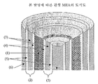
중앙 기체 확산 기판의 디자인은 평면형 또는 관형일 수 있다. 도 1은 평면 구조의 예를 도시하고, 도 2는 관형 구조의 예를 도시한다. 두 도면 모두에서, (1)은 중앙 기체 확산 기판이다. 중앙 기체 확산 기판의 각 면에는 촉매 코팅막 (2)가 적용되어 있다. 촉매 코팅막은 제 1 및 제 2 전해질 (3), 제 1 및 제 2 촉매층 (4) 및 제 3 및 제 4 촉매층 (5)로 이루어진다. 각 촉매층 (5)에 전류 수집수단 (6)이 적용된다.The design of the central gas diffusion substrate can be planar or tubular. 1 shows an example of a planar structure, and FIG. 2 shows an example of a tubular structure. In both figures, (1) is the central gas diffusion substrate. The
한 실시양태에서, 중앙 기체 확산 기판은 다공성 전도성 카본 구조체이다. 구조체에는 기판에 기체를 전달하는 매니폴드 수단이 제공되거나 상기 수단에 구조체가 정합될 수 있고, 측면 모서리를 따라 밀봉 또는 측면 모서리 및 기체 도입점에서 떨어져 있는 하단 모서리를 따라 밀봉되어 기체 또는 액체 손실을 방지하고, 기체 또는 액체를 기판을 통해 촉매층으로 강제할 수 있다. 이러한 기체 확산 기판은, 직조 또는 부직 전도성 섬유 또는 다른 전도성 다공성 구조체로부터 제조되는 강성 또는 비강성 카본(또는 다른 전도성 다공성 재료) 시트로서 그 자체로 공지되어 있고, 카본지 (예, 일본, 토레이 인더스트리즈(Toray Industries)사제, 토레이® 종이(Toray® paper) 또는 일본, 미츠비시 레이온(Mitsubishi Rayon)사제, U 105 또는 Ul 07 종이), 카본 직포 (예, 일본, 미츠비시 케미칼(Mitsubishi Chemicals)사제 카본포의 MK 시리즈) 또는 부직 카본 섬유 웹 (예, 미국, 이-테크(E-TEK)사제 부직 기판의 ELAT 시리즈; 독일, 프로이덴버그 FCCT KG(Freudenberg FCCT KG)사제 H2315 시리즈; 또는 독일, SGL 테크놀로지 GmbH(SGL Technologies GmbH)사제 시그라세트(Sigracet)® 시리즈)를 기재로 할 수 있다. 카본지, 카본포 또는 카본웹은 기판내에 매립되거나 평면에 코팅된 또는 이의 조합인 입상 물질을 이용하여 통상 개질된다. 입상 물질은 통상 카본 블랙과 중합체, 예컨대 폴리테트라플루오로에틸렌 (PTFE)의 혼합물이다. 적합하게 기체 확산 기판의 두께는 100 내지 300 μm이다. 일부 경우, 입상 물질, 예컨대 카본 블랙 및 PTFE의 층이 촉매층에 접촉하는 기체 확산 기판의 표면상에 있을 수 있다. 부가적으로, 기체 전달을 촉진하는 채널을 둘러싸는 다공성 카본 매트릭스와 같은 만족스러운 구조체, 예컨대 카본 매트릭스 내 카본 튜브를 구상할 수 있다. 이러한 튜브는 WO02/15308에 개시된 것과 유사할 수 있고, 또는 기체 유동 특성이 MEA의 요건을 만족시키는 것을 전제로 카본 나노튜브로 확장할 수 있다. 또 다른 실시양태는 통합적 가스 공급 채널을 가지거나 또는 가지지 않는 입상 카본 또는 흑연으로 제조된 강성 다공성 카본 시트를 포함시킬 수 있다. 이는 다공성 세라믹 압출 필터, 예컨대 디젤 엔진 배기가스 처리용 디젤 입상 필터에 사용되는 필터와 유사하다.In one embodiment, the central gas diffusion substrate is a porous conductive carbon structure. The structure may be provided with a manifold means for delivering gas to the substrate, or the structure may be mated to the means, and sealed along the side edges or sealed along the side edges and the bottom edge away from the gas introduction point to reduce gas or liquid loss. And gas or liquid can be forced through the substrate into the catalyst layer. Such gas diffusion substrates are known per se as rigid or non-rigid carbon (or other conductive porous material) sheets made from woven or nonwoven conductive fibers or other conductive porous structures, and are made of carbon paper (e.g., Japan, Toray Industries, Ltd.). MK of Toray Industries, Toray® paper or Japan, Mitsubishi Rayon, U 105 or Ul 07 paper, carbon cloth (e.g., Japan, Mitsubishi Chemicals, carbon cloth) Series) or nonwoven carbon fiber web (e.g. ELAT series of non-woven substrates from E-TEK, USA; H2315 series from Freudenberg FCCT KG, Germany; or SGL Technology GmbH, Germany Sigracet® series from SGL Technologies GmbH). Carbon paper, carbon cloth, or carbon webs are typically modified using particulate materials that are embedded in a substrate, coated on a plane, or a combination thereof. The particulate material is usually a mixture of carbon black and a polymer such as polytetrafluoroethylene (PTFE). Suitably the thickness of the gas diffusion substrate is between 100 and 300 μm. In some cases, a layer of particulate material such as carbon black and PTFE may be on the surface of the gas diffusion substrate in contact with the catalyst layer. Additionally, it is possible to envision a satisfactory structure, such as a porous carbon matrix surrounding the channel that facilitates gas delivery, such as a carbon tube in a carbon matrix. Such a tube can be similar to that disclosed in WO02 / 15308, or can be expanded to carbon nanotubes provided the gas flow characteristics meet the requirements of the MEA. Another embodiment may include a rigid porous carbon sheet made of particulate carbon or graphite with or without an integrated gas supply channel. This is similar to the filters used in porous ceramic extrusion filters, such as diesel particulate filters for diesel engine exhaust treatment.
다르게는, 중앙 기체 확산 기판은 기판의 양면에 하나 이상의 홈(groove)을 갖는 금속 또는 흑연 기판이다. 홈은 기체 또는 액체의 전달 및 분배를 가능하게 하고 일반적으로 유동장 홈으로 지칭된다. 다르게는, 유동장 홈이 기판의 두께를 가로지를 수 있다. Alternatively, the central gas diffusion substrate is a metal or graphite substrate having one or more grooves on both sides of the substrate. The grooves enable the delivery and distribution of gases or liquids and are generally referred to as flow field grooves. Alternatively, the flow field grooves can cross the thickness of the substrate.
다르게는, 중앙 기체 확산 기판은 안에 리세스(recess)가 형성되어 있는 두 개 이상의 다공성 전도성 층을 포함하고, US2007/0054175에 추가로 설명된다. 리세스는 일정 패턴으로 배치되고, 층을 조합할 때 리세스는 적어도 부분적으로 중첩되어 기체 또는 액체의 분배를 위한 채널 구조를 형성한다.Alternatively, the central gas diffusion substrate comprises two or more porous conductive layers with recesses formed therein, and further described in US2007 / 0054175. The recesses are arranged in a pattern, and when combining the layers the recesses at least partially overlap to form a channel structure for the distribution of gas or liquid.
MEA 구조의 나머지 부분은 본질적으로 통상적이거나 또는 통상적 구성요소의 변경된 버전이다.The remainder of the MEA structure is essentially conventional or a modified version of conventional components.
한 실시양태에서, 제 1 및 제 2 촉매층은 동일하며 적합하게 애노드 촉매층으로 작용하고, 제 3 및 제 4 촉매층은 동일하며 적합하게 캐소드 촉매층으로 작용한다. 다르게는, 제 1 및 제 2 촉매층은 캐소드 촉매층으로 작용하고, 제 3 및 제 4 촉매층은 애노드 층으로 작용한다.In one embodiment, the first and second catalyst layers are identical and suitably serve as anode catalyst layers, and the third and fourth catalyst layers are identical and suitably serve as cathode catalyst layers. Alternatively, the first and second catalyst layers act as cathode catalyst layers and the third and fourth catalyst layers act as anode layers.
촉매층은 미분된 금속 분말 (금속 블랙) 또는 작은 금속 입자가 전기전도성 입상 카본 지지체상에 분산되어 있는 지지된 촉매일 수 있는 전기촉매를 포함한다. 전기촉매 금속은 적합하게 하기에서 선택된다:The catalyst layer comprises an electrocatalyst, which can be a finely divided metal powder (metal black) or a supported catalyst in which small metal particles are dispersed on an electrically conductive particulate carbon support. The electrocatalyst metal is suitably selected from:
(i) 백금족 금속 (백금, 팔라듐, 로듐, 루테늄, 이리듐 및 오스뮴), (i) platinum group metals (platinum, palladium, rhodium, ruthenium, iridium and osmium),
(ii) 금 또는 은, (ii) gold or silver,
(iii) 베이스 금속, (iii) a base metal,
또는 하나 이상의 상기 금속 또는 이의 산화물을 포함하는 합금 또는 혼합물. 바람직한 전기촉매 금속은 루테늄과 같은 다른 귀금속과 합금될 수 있는 백금 또는 몰리브덴 또는 텅스텐과 같은 베이스 금속이다. 전기촉매가 지지된 촉매이면, 금속 입자의 카본 지지체 재료상의 적재량은 적합하게 10-100 중량%, 바람직하게는 15-75 중량%이다.Or an alloy or mixture comprising at least one of the above metals or oxides thereof. Preferred electrocatalyst metals are platinum or base metals such as molybdenum or tungsten which can be alloyed with other precious metals such as ruthenium. If the electrocatalyst is supported catalyst, the loading of the metal particles on the carbon support material is suitably 10-100% by weight, preferably 15-75% by weight.
전기촉매층은 다른 구성요소, 예컨대 층내 이온 전도성을 개선시키기 위하여 포함되는 이온-전도성 중합체를 적합하게 포함한다. 막전극 어셈블리 내에 층을 포함시키기 위하여, 층을 기체 확산 기판상에 형성하거나 (기체 확산 전극 형성), 또는 층을 전해질 막상에 직접 형성 (촉매 코팅막을 형성)할 수 있다. 적합하게, 전기촉매 잉크를 예를 들어 EP 0 731 520에 기재된 바와 같이 형성한 후, 당업자에게 공지된 방법, 예를 들어 스크린 프린팅, 잉크젯 프린팅, 롤링, 여과 진공 증착, 분무 증착, 주조, 압출 등으로 막 또는 기체 확산 기판에 잉크를 적용한다.The electrocatalyst layer suitably includes other components, such as ion-conducting polymers included to improve ionic conductivity in the layer. In order to include the layer in the membrane electrode assembly, the layer may be formed on the gas diffusion substrate (gas diffusion electrode formation), or the layer may be directly formed on the electrolyte membrane (forming the catalyst coating film). Suitably, after forming the electrocatalyst ink as described, for example, in
전해질은 임의의 이온-전도성 전해질, 예를 들어 당업자에게 공지된 임의 유형의 이온-전도성 막일 수 있다. 최신 막전극 어셈블리에서, 막은 흔히 나피온(Nafion)®(듀폰;DuPont), 플레미온(Flemion)®(아사히 글래스;Asahi Glass), 및 아시플렉스(Aciplex)®(아사히 가세이;Asahi Kasei)와 같은 퍼플루오르화 설폰산 재료를 기재로 한다. 이 막은 프로톤 전도성 재료 및 기계적 강도와 같은 특성을 부여하는 다른 재료를 포함하는 복합막일 수 있다. 예를 들어, 막은 EP 875 524에 기재된 바와 같은, 실리카 섬유의 매트릭스 및 프로톤 전도성 막을 포함하거나, 발포된 PTFE 기판을 포함할 수 있다. 이 막의 두께는 적합하게 200μm 미만, 바람직하게는 50μm 미만이다.The electrolyte can be any ion-conducting electrolyte, for example any type of ion-conducting membrane known to those skilled in the art. In modern membrane electrode assemblies, membranes are often such as Nafion® (DuPont), Flemion® (Asahi Glass), and Asiplex® (Asahi Kasei). Based on perfluorinated sulfonic acid materials. This membrane may be a composite membrane comprising a proton conductive material and other materials that impart properties such as mechanical strength. For example, the membrane may comprise a matrix of silica fibers and a proton conductive membrane, as described in EP 875 524, or may comprise a foamed PTFE substrate. The thickness of this film is suitably less than 200 μm, preferably less than 50 μm.
전류는 각 전류 수집수단의 제 2 면 또는 각 모서리로부터 바람직하게 취해지지만, 중앙 제 1 전도성 기체 확산 기판의 모서리에서도 취할 수 있고, 이로 인해 본 발명의 MEA 시스템에서의 저항성 손실을 최소할 수 있을 것으로 생각된다.The current is preferably taken from the second side or each corner of each current collecting means, but can also be taken from the edge of the central first conductive gas diffusion substrate, thereby minimizing resistive losses in the MEA system of the present invention. I think.
다공성 전류 수집수단은 400 μm 미만이고, 전도성 금속선의 어레이, 그리드 또는 메쉬일 수 있고, 또는 금속 또는 전도성 비금속 발포체일 수 있다. 다르게는, 전류 수집수단은 직조 또는 부직 전도성 섬유로부터 제조된 통상의 기체 확산 기판 또는 다른 전도성 다공성 구조체 및 상기 상술한 바와 같은 것일 수 있다. 전류 수집수단의 단순한 필요조건은 전류 전달에 효과적이고, 제 2 촉매층으로 연료의 흐름, 바람직하게는 산화제 흐름을 반드시 허용하는 것이다.The porous current collecting means is less than 400 μm and may be an array, grid or mesh of conductive metal wires, or may be a metal or conductive nonmetallic foam. Alternatively, the current collecting means may be a conventional gas diffusion substrate or other conductive porous structure made from woven or nonwoven conductive fibers and as described above. The simple requirement of the current collecting means is to be effective for current transfer and to allow the flow of fuel, preferably oxidant, to the second catalyst bed.
선택되는 특정 구성요소는 본 발명에 결정적이지 않고, 당업자는 특정 요건에 맞게 적절한 구성요소를 용이하게 선택할 수 있다.The particular component selected is not critical to the present invention and one of ordinary skill in the art can easily select an appropriate component to suit particular requirements.
바람직한 구성 방법은 촉매 코팅막 또는 기체 확산 전극의 사용을 포함한다. 그러나 당업자는 다른 방법들도 사용할 수 있다.Preferred construction methods include the use of a catalyst coating film or a gas diffusion electrode. However, those skilled in the art may use other methods.
본 발명의 주요 장점은 하나의 기체 확산층 및 두 개의 유동장 플레이트에 의하여 두개의 분리된 통상 MEA보다 얇은 구성으로 두개의 MEA의 출력을 수득하며 전지 중량 및 부피를 유의한 비율로 줄일 수 있다는 것이다.The main advantage of the present invention is that the output of two MEAs can be obtained in a configuration thinner than two separate conventional MEAs by one gas diffusion layer and two flow field plates and the cell weight and volume can be reduced in a significant proportion.
본 발명의 신규한 MEA 구조체는 평면형 또는 관형이고, 통상의 구성에 비하여 중량 및 부피가 더 작은 연료 전지의 구성을 가능하게 하고, 이는 휴대용으로 개발되는 더 작은 연료 전지 시스템에서 매우 유리할 수 있다. 평면형 MEA의 경우, 정사각형 또는 직사각형일 수 있고, 또는 디스크형 또는 적용에 적합한 임의의 다른 모양일 수 있다. 본 발명에 따른 MEA가 도입된 연료 전지는 유연할 수도 있어서 모든 구성요소의 만족스러운 가공을 가능하게 한다. 이러한 연료 전지의 작동은 수동적 (연료 및 공기를 순환시키기 위해 중력 및 자연적 대류에 의존함) 또는 반-수동적(연료 및 공기의 순환을 돕기 위해 저전력 소모 팬을 사용함)일 수 있어서 전력원으로서의 그 사용을 더 단순화시킨다. 작동 도중에 생성되는 물은 밸브 및 퍼지 수단을 사용하여 제거될 수 있고, 또는 연료 전극으로의 역-확산을 통해 재순환, 또는 연료 공급물을 가습시킬 목적으로 연료 공급물로 순환될 수 있다. 이러한 연료 전지는 물속에서 자립형일 수 있다.The novel MEA structures of the present invention are planar or tubular, and allow for the construction of fuel cells that are smaller in weight and volume than conventional configurations, which can be very advantageous in smaller fuel cell systems that are developed to be portable. In the case of a planar MEA, it may be square or rectangular, or may be disc shaped or any other shape suitable for the application. The fuel cell incorporating the MEA according to the present invention may be flexible to enable satisfactory processing of all components. The operation of such fuel cells can be passive (depending on gravity and natural convection to circulate fuel and air) or semi-passive (using low-power consuming fans to help circulate fuel and air) and use it as a power source. To further simplify. The water produced during operation may be removed using valves and purge means, or may be circulated to the fuel feed for the purpose of recirculation through back-diffusion to the fuel electrode, or for humidifying the fuel feed. Such fuel cells may be freestanding in water.
수소 또는 액체 탄화수소 연료, 예를 들어 메탄올, 에탄올 또는 붕수소 나트륨 수용액 수소를 연료로서 사용하는 것이 바람직하다. 바람직하게는 공기가 산화제로 사용된다.Preference is given to using hydrogen or liquid hydrocarbon fuels such as methanol, ethanol or aqueous sodium borohydride as fuel. Preferably air is used as oxidant.
본 발명에 따른 단일 MEA가 고 전류 밀도 및 상응하는 전력 밀도를 갖는 연료 전지를 형성할 수 있지만, 스택을 형성하는 것이 바람직할 수 있다. 스택은 실질적으로 평탄한 연료 전지의 어레이를 포함할 수 있고, 또는 통상의 방식으로 MEA를 서로 결합시킨 작은 스택을 형성할 수 있고, 또는 당업자에게 공지된 임의의 다른 배열일 수 있다. 실제 스택 구성은 목적하는 전압 및 다른 요건에 의존적이다. 하나 이상의 변환기 또는 전압 스테퍼를 사용하여 당업계에 공지된 바와 같이 임의의 특정 적용에서 목적하는 전압 및 전류를 제공할 수 있다.Although a single MEA according to the present invention can form a fuel cell having a high current density and corresponding power density, it may be desirable to form a stack. The stack may comprise an array of substantially flat fuel cells, or may form a small stack that couples MEAs together in a conventional manner, or may be any other arrangement known to those skilled in the art. The actual stack configuration depends on the desired voltage and other requirements. One or more transducers or voltage steppers may be used to provide the desired voltage and current in any particular application as is known in the art.
본 발명의 MEA가 도입된 연료 전지의 제 1 용도는 예를 들어 소형 컴퓨터 (랩탑, 노트북, PDA), 개인 통신수단, 예컨대 휴대전화 및 라디오, 개인 오락 장치 등에서의 배터리에 대한 대안적인 발전 장치가 될 것으로 기대되고, 그 뿐만 아니라 당업자는 많은 다른 용도를 고려할 수 있다. 본 발명은 전력을 필요로 하는 장치의 요건을 만족시키는 더 다양한 선택권을 연료전지 디자이너 및 공학자들에게 더 유용하게 제공할 것으로 생각되지만, 어떤 특정 디자인에 국한되는 것을 원하지 않는다.The primary use of a fuel cell incorporating the MEA of the present invention is for example an alternative power generation device for batteries in small computers (laptops, notebooks, PDAs), personal communication means such as mobile phones and radios, personal entertainment devices and the like. It is anticipated that, as well as those skilled in the art can contemplate many other uses. While the present invention is believed to provide fuel cell designers and engineers with more options to meet the requirements of devices requiring power, they do not wish to be limited to any particular design.
도 1은 본 발명에 따른 평면형 MEA의 도식도이다.1 is a schematic diagram of a planar MEA according to the present invention.
도 2는 본 발명에 따른 관형 MEA의 도식도이다.2 is a schematic of a tubular MEA in accordance with the present invention.
도 3은 카본 모노리스의 벽 및 채널 치수를 나타내는 도식도이다.3 is a schematic showing the wall and channel dimensions of a carbon monolith.
도 4는 공기-흡입식 수소 연료 전지의 공기 분극화 및 전력 밀도를 나타내는 그래프이다.4 is a graph showing air polarization and power density of an air-suction hydrogen fuel cell.
본 발명은 이제 본 발명을 제한하지 않는 단지 실시예로써 이를 참조하여 더 예시될 것이다.The invention will now be further illustrated with reference to the following examples, which are not intended to limit the invention.
기체 유동 채널을 갖는 MEA의 중앙 전도성 기체-분배 구성요소를 다공성 카본 모노리스로부터 900 ㎛의 통상적 두께로 도 3에 보여지는 바와 같이 제작하였다. 분말화된 페놀 수지 도우를 사용하여 단일층 다이를 통해 압출시켜 모노리스를 만들었다. "그린" 모노리스를 CO2 분위기하 800 ℃에서 탄화시킨 후, 헬륨 분위기하 고온에서 (1500 ℃) 열-처리하였다.The central conductive gas-distributing component of the MEA with gas flow channels was fabricated from porous carbon monolith as shown in FIG. 3 with a typical thickness of 900 μm. Monolith was made by extrusion through a single layer die using a powdered phenolic resin dough. The “green” monolith was carbonized at 800 ° C. under CO 2 atmosphere and then heat-treated at high temperature (1500 ° C.) under helium atmosphere.
3 개의 모노리스 (각각 대략 1.4 cm×5.5 cm)로 모노리스 어셈블리를 제조하였다. 모노리스를 서로 평행하게 나란히 놓고 은-충전 에폭시 수지를 사용하여 모서리-대-모서리로 전기적으로 연결하여 대략 4.2×5.5×0.09 cm 구조체를 형성하였다. 애노드에 전기적 접촉부를 형성하기 위하여 구리선을 모노리스 사이의 은-충전 에폭시내에 배치하였다.Monolith assemblies were prepared with three monoliths (approximately 1.4 cm x 5.5 cm each). The monoliths were placed side by side parallel to each other and electrically connected to the edge-to-edge using silver-filled epoxy resin to form approximately 4.2 × 5.5 × 0.09 cm structures. Copper wire was placed in the silver-filled epoxy between the monoliths to form electrical contacts at the anode.
실험에 사용한 막은 Asahi Glass (Japan)사제 SH-30이었다. 탄소상 Pt를 함유하는 수성 촉매 잉크 및 이오노머를 PTFE에 코팅하고, 150 ℃에서 막의 양면에 전달하여, 촉매 코팅막 (CCM) 구조체를 형성하였다. 이 실험에서 Pt 적재량은 0.45 내지 0.65 mg/cm2이었다. 동일한 촉매를 애노드 및 캐소드상에 사용하였다. Toray® TGP-H-60 카본지와 소수성 마이크로-다공성층 (이오노머, 카본 및 PTFE를 함유함)을 기체 확산층 기판으로 외부 캐소드 면에 사용하였다.The film used for the experiment was SH-30 manufactured by Asahi Glass (Japan). The aqueous catalyst ink and ionomer containing Pt on carbon were coated on PTFE and transferred to both sides of the membrane at 150 ° C. to form a catalyst coating membrane (CCM) structure. Pt loadings in this experiment were 0.45 to 0.65 mg / cm 2 . The same catalyst was used on the anode and cathode. Toray® TGP-H-60 carbon paper and a hydrophobic micro-porous layer (containing ionomer, carbon and PTFE) were used as the gas diffusion layer substrate on the outer cathode side.
모노리스 어셈블리의 각 면에 CCM을 하나씩 놓았다. WO2006/032894에 기재되어 있고, 3 cm×3 cm 창을 갖는 열가소성 모서리 보호 재료 (H2에 불침투성임) 를 90 ℃에서 CCM의 양면에 결합시켰다. 그 후 하나의 캐소드 기판 및 CCM을 150 ℃에서 모노리스 어셈블리의 각 면에 고온-프레스시켰다. CCM-모노리스 어셈블리를 시험 전지에 넣고, 공기의 자유로운 접근을 가능하게 하는 개방 부위를 갖는 흑연 프레임으로 압축하였다. 캐소드는 완전 공기-흡입식(air-breathing)으로, 즉 외부 송풍기가 사용되지 않았다. 캐소드에 전기적 접촉부는 카본지에 접촉하고 있는 흑연 프레임을 통해 형성된다.One CCM was placed on each side of the monolith assembly. A thermoplastic corner protective material (impermeable to H 2 ), described in WO2006 / 032894, having a 3 cm × 3 cm window, was bonded to both sides of the CCM at 90 ° C. One cathode substrate and CCM were then hot-pressed at each side of the monolith assembly at 150 ° C. The CCM-monolith assembly was placed in a test cell and pressed into a graphite frame with open areas that allow free access of air. The cathode was fully air-breathing, ie no external blower was used. Electrical contacts to the cathode are formed through the graphite frame in contact with the carbon paper.
실제 실험을 위하여, 모노리스 채널의 한 말단을 막고(막힌 말단), 시판되는 금속 수소화물 수소 저장 장치(Udomi, 독일)로부터 수소를 다른 한 말단으로 공급하였다. 분극화 곡선을 상응하는 전력 밀도 곡선과 함께 도 4 에 도시하였다.For practical experiments, one end of the monolith channel was blocked (closed end) and hydrogen was supplied to the other end from a commercial metal hydride hydrogen storage device (Udomi, Germany). Polarization curves are shown in FIG. 4 with corresponding power density curves.
Claims (18)
Applications Claiming Priority (2)
| Application Number | Priority Date | Filing Date | Title |
|---|---|---|---|
| GBGB0617806.5A GB0617806D0 (en) | 2006-09-11 | 2006-09-11 | Fuel cell assembly |
| GB0617806.5 | 2006-09-11 |
Publications (1)
| Publication Number | Publication Date |
|---|---|
| KR20090063213A true KR20090063213A (en) | 2009-06-17 |
Family
ID=37232689
Family Applications (1)
| Application Number | Title | Priority Date | Filing Date |
|---|---|---|---|
| KR1020097004940A KR20090063213A (en) | 2006-09-11 | 2007-09-11 | Fuel cell assembly |
Country Status (8)
| Country | Link |
|---|---|
| US (1) | US8318373B2 (en) |
| EP (1) | EP2070147B1 (en) |
| JP (2) | JP5766401B2 (en) |
| KR (1) | KR20090063213A (en) |
| CN (1) | CN101512819B (en) |
| CA (1) | CA2663278A1 (en) |
| GB (1) | GB0617806D0 (en) |
| WO (1) | WO2008032115A1 (en) |
Families Citing this family (9)
| Publication number | Priority date | Publication date | Assignee | Title |
|---|---|---|---|---|
| GB0711882D0 (en) | 2007-06-20 | 2007-07-25 | Johnson Matthey Plc | Catalyst layer |
| EP2859135A4 (en) * | 2012-06-12 | 2015-09-09 | Univ Wollongong | Gas permeable electrodes and electrochemical cells |
| WO2013185163A1 (en) | 2012-06-12 | 2013-12-19 | Monash University | Breathable electrode and method for use iν water splitting |
| CN105637123A (en) | 2013-07-31 | 2016-06-01 | 奥克海德莱克斯控股有限公司 | Electro-synthetic or electro-energy cell with gas diffusion electrode(s) |
| EP3653953A1 (en) * | 2015-03-09 | 2020-05-20 | Johnson IP Holding, LLC | Thermo-electrochemical convertor with integrated energy storage |
| WO2019065985A1 (en) | 2017-09-29 | 2019-04-04 | ホヤ レンズ タイランド リミテッド | Spectacle lens and spectacles |
| WO2019065989A1 (en) | 2017-09-29 | 2019-04-04 | ホヤ レンズ タイランド リミテッド | Spectacle lens and spectacles |
| WO2020160424A1 (en) | 2019-02-01 | 2020-08-06 | Aquahydrex, Inc. | Electrochemical system with confined electrolyte |
| CN114628771B (en) * | 2020-12-10 | 2023-07-07 | 北京好风光储能技术有限公司 | Winding type battery |
Family Cites Families (29)
| Publication number | Priority date | Publication date | Assignee | Title |
|---|---|---|---|---|
| JPH05144444A (en) * | 1991-11-25 | 1993-06-11 | Toshiba Corp | Fuel cell and electrode manufacturing method |
| US5364711A (en) * | 1992-04-01 | 1994-11-15 | Kabushiki Kaisha Toshiba | Fuel cell |
| US5800938A (en) * | 1992-09-22 | 1998-09-01 | Tanaka Kikinzoku Kogyo K.K. | Sandwich-type solid polymer electrolyte fuel cell |
| JPH0850914A (en) * | 1994-08-08 | 1996-02-20 | Fujikura Ltd | Cylindrical layer-built fuel cell |
| GB9504713D0 (en) | 1995-03-09 | 1995-04-26 | Johnson Matthey Plc | Improved electrocatalytic material |
| US5945231A (en) * | 1996-03-26 | 1999-08-31 | California Institute Of Technology | Direct liquid-feed fuel cell with membrane electrolyte and manufacturing thereof |
| WO1997047052A1 (en) * | 1996-06-05 | 1997-12-11 | Southwest Research Institute | Cylindrical proton exchange membrane fuel cells and methods of making same |
| US6054228A (en) * | 1996-06-06 | 2000-04-25 | Lynntech, Inc. | Fuel cell system for low pressure operation |
| US5858569A (en) * | 1997-03-21 | 1999-01-12 | Plug Power L.L.C. | Low cost fuel cell stack design |
| GB9708365D0 (en) | 1997-04-25 | 1997-06-18 | Johnson Matthey Plc | Proton conducting membranes |
| US5922486A (en) * | 1997-05-29 | 1999-07-13 | The Dow Chemical Company | Cosintering of multilayer stacks of solid oxide fuel cells |
| US7098163B2 (en) * | 1998-08-27 | 2006-08-29 | Cabot Corporation | Method of producing membrane electrode assemblies for use in proton exchange membrane and direct methanol fuel cells |
| GB0020051D0 (en) | 2000-08-16 | 2000-10-04 | Mat & Separations Tech Int Ltd | Improved fuel cell structure |
| US7081317B2 (en) * | 2001-03-29 | 2006-07-25 | Matsushita Electric Industrial Co., Ltd. | Polymer electrolyte thin film fuel cell and method of operating the same |
| US6756150B2 (en) * | 2002-04-08 | 2004-06-29 | Plug Power Inc. | Fuel cell having a non-electrolytic layer |
| KR100450820B1 (en) * | 2002-04-23 | 2004-10-01 | 삼성에스디아이 주식회사 | Air breathing direct methanol fuel cell pack |
| JP2003346867A (en) * | 2002-05-27 | 2003-12-05 | Seiko Epson Corp | Fuel cell and its manufacturing method |
| JP4781818B2 (en) * | 2003-06-24 | 2011-09-28 | 旭硝子株式会社 | Method for producing membrane electrode assembly for polymer electrolyte fuel cell |
| US20050014056A1 (en) * | 2003-07-14 | 2005-01-20 | Umicore Ag & Co. Kg | Membrane electrode unit for electrochemical equipment |
| DE112004001357T5 (en) * | 2003-07-22 | 2006-07-20 | E.I. Dupont De Nemours And Co., Wilmington | A method of fabricating planar framed membrane electrode assembly arrays and fuel cells containing the same |
| WO2005027244A2 (en) | 2003-09-10 | 2005-03-24 | Hollingsworth & Vose Company | Fuel cell gas diffusion layer |
| DE10342199B4 (en) | 2003-09-13 | 2007-02-08 | Daimlerchrysler Ag | Method for producing a gas diffusion layer for a fuel cell |
| US7157178B2 (en) * | 2003-11-24 | 2007-01-02 | General Motors Corporation | Proton exchange membrane fuel cell |
| GB0421254D0 (en) | 2004-09-24 | 2004-10-27 | Johnson Matthey Plc | Membrane electrode assembly |
| DE112006000121B4 (en) * | 2005-02-04 | 2013-02-21 | Toyota Jidosha Kabushiki Kaisha | Hollow-type fuel cell |
| CN100463260C (en) * | 2005-05-14 | 2009-02-18 | 鸿富锦精密工业(深圳)有限公司 | Gas diffusion electrode and mfg. method thereof |
| JP4949655B2 (en) * | 2005-08-09 | 2012-06-13 | 株式会社日立製作所 | FUEL CELL, FUEL CELL POWER SUPPLY SYSTEM, AND ELECTRONIC DEVICE USING THE SAME |
| EP1760808B1 (en) * | 2005-09-06 | 2008-07-23 | Sgl Carbon Ag | Electrodes for a fuel cell |
| KR100659132B1 (en) * | 2006-02-07 | 2006-12-19 | 삼성에스디아이 주식회사 | A membrane electrode assembly for fuel cell, a method for preparing the same and a fuel cell comprising the same |
-
2006
- 2006-09-11 GB GBGB0617806.5A patent/GB0617806D0/en not_active Ceased
-
2007
- 2007-09-11 CN CN2007800336148A patent/CN101512819B/en not_active Expired - Fee Related
- 2007-09-11 US US12/440,691 patent/US8318373B2/en not_active Expired - Fee Related
- 2007-09-11 WO PCT/GB2007/050534 patent/WO2008032115A1/en active Application Filing
- 2007-09-11 CA CA002663278A patent/CA2663278A1/en not_active Abandoned
- 2007-09-11 KR KR1020097004940A patent/KR20090063213A/en active Search and Examination
- 2007-09-11 EP EP07804440A patent/EP2070147B1/en active Active
- 2007-09-11 JP JP2009527214A patent/JP5766401B2/en not_active Expired - Fee Related
-
2013
- 2013-09-24 JP JP2013197382A patent/JP2014038857A/en active Pending
Also Published As
| Publication number | Publication date |
|---|---|
| US20100009232A1 (en) | 2010-01-14 |
| JP2014038857A (en) | 2014-02-27 |
| CA2663278A1 (en) | 2008-03-20 |
| GB0617806D0 (en) | 2006-10-18 |
| JP2010503167A (en) | 2010-01-28 |
| EP2070147A1 (en) | 2009-06-17 |
| US8318373B2 (en) | 2012-11-27 |
| CN101512819B (en) | 2013-02-06 |
| EP2070147B1 (en) | 2012-09-05 |
| WO2008032115A1 (en) | 2008-03-20 |
| CN101512819A (en) | 2009-08-19 |
| JP5766401B2 (en) | 2015-08-19 |
Similar Documents
| Publication | Publication Date | Title |
|---|---|---|
| US7166381B2 (en) | Air breathing direct methanol fuel cell pack | |
| US7655335B2 (en) | Air breathing direct methanol fuel cell pack | |
| KR101284946B1 (en) | Electrochemical device | |
| US8318373B2 (en) | Fuel cell assembly | |
| JP5198044B2 (en) | Direct oxidation fuel cell | |
| US20060240311A1 (en) | Membrane-electrode unit for direct methanol fuel cells and method for the production thereof | |
| US7964323B2 (en) | Direct oxidation fuel cell | |
| KR100796886B1 (en) | Direct oxidation fuel cell and method for operating direct oxidation fuel cell system | |
| JP2006294603A (en) | Direct type fuel cell | |
| JP2007234589A (en) | Direct oxidation fuel cell and method for operating direct oxidation fuel cell system | |
| US8632927B2 (en) | Membraneless fuel cell and method of operating same | |
| JP2007134306A (en) | Direct oxidation fuel cell and membrane electrode assembly thereof | |
| US8076040B2 (en) | Direct oxidation fuel cell | |
| JP2007042600A (en) | Fuel cell | |
| JP2009283350A (en) | Power generator and fuel cell | |
| JP3619826B2 (en) | Fuel cell electrode and fuel cell | |
| JP2009277465A (en) | Polymer electrolyte type fuel cell stack | |
| US20140087284A1 (en) | Direct oxidation fuel cell and method for producing catalyst-coated membrane used therefor | |
| JP2006216404A (en) | Fuel cell | |
| KR101093708B1 (en) | A electrode for fuel cell and a fuel cell comprising the same | |
| KR101155912B1 (en) | A membrane electrode assembly for fuel cell and a fuel cell comprising the same | |
| JP2006066209A (en) | Direct methanol type fuel cell | |
| KR20220170011A (en) | Ultra-thin tube type PEM fuel cell | |
| Baglio et al. | Status of technology and perspectives for portable applications of direct methanol fuel cells | |
| US20100248074A1 (en) | Membrane electrode assembly for direct oxidation fuel cell and direct oxidation fuel cell including the same |
Legal Events
| Date | Code | Title | Description |
|---|---|---|---|
| A201 | Request for examination | ||
| AMND | Amendment | ||
| E902 | Notification of reason for refusal | ||
| N231 | Notification of change of applicant | ||
| AMND | Amendment | ||
| E601 | Decision to refuse application | ||
| AMND | Amendment | ||
| J201 | Request for trial against refusal decision | ||
| B601 | Maintenance of original decision after re-examination before a trial | ||
| J301 | Trial decision |
Free format text: TRIAL DECISION FOR APPEAL AGAINST DECISION TO DECLINE REFUSAL REQUESTED 20140818 Effective date: 20160125 Free format text: TRIAL NUMBER: 2014101005112; TRIAL DECISION FOR APPEAL AGAINST DECISION TO DECLINE REFUSAL REQUESTED 20140818 Effective date: 20160125 |