EP2070147B1 - Fuel cell assembly - Google Patents
Fuel cell assembly Download PDFInfo
- Publication number
- EP2070147B1 EP2070147B1 EP07804440A EP07804440A EP2070147B1 EP 2070147 B1 EP2070147 B1 EP 2070147B1 EP 07804440 A EP07804440 A EP 07804440A EP 07804440 A EP07804440 A EP 07804440A EP 2070147 B1 EP2070147 B1 EP 2070147B1
- Authority
- EP
- European Patent Office
- Prior art keywords
- face
- gas diffusion
- catalyst
- layers
- contact
- Prior art date
- Legal status (The legal status is an assumption and is not a legal conclusion. Google has not performed a legal analysis and makes no representation as to the accuracy of the status listed.)
- Active
Links
Images


Classifications
-
- H—ELECTRICITY
- H01—ELECTRIC ELEMENTS
- H01M—PROCESSES OR MEANS, e.g. BATTERIES, FOR THE DIRECT CONVERSION OF CHEMICAL ENERGY INTO ELECTRICAL ENERGY
- H01M4/00—Electrodes
- H01M4/86—Inert electrodes with catalytic activity, e.g. for fuel cells
-
- H—ELECTRICITY
- H01—ELECTRIC ELEMENTS
- H01M—PROCESSES OR MEANS, e.g. BATTERIES, FOR THE DIRECT CONVERSION OF CHEMICAL ENERGY INTO ELECTRICAL ENERGY
- H01M8/00—Fuel cells; Manufacture thereof
- H01M8/06—Combination of fuel cells with means for production of reactants or for treatment of residues
- H01M8/0606—Combination of fuel cells with means for production of reactants or for treatment of residues with means for production of gaseous reactants
- H01M8/065—Combination of fuel cells with means for production of reactants or for treatment of residues with means for production of gaseous reactants by dissolution of metals or alloys; by dehydriding metallic substances
-
- H—ELECTRICITY
- H01—ELECTRIC ELEMENTS
- H01M—PROCESSES OR MEANS, e.g. BATTERIES, FOR THE DIRECT CONVERSION OF CHEMICAL ENERGY INTO ELECTRICAL ENERGY
- H01M4/00—Electrodes
- H01M4/86—Inert electrodes with catalytic activity, e.g. for fuel cells
- H01M4/8605—Porous electrodes
-
- H—ELECTRICITY
- H01—ELECTRIC ELEMENTS
- H01M—PROCESSES OR MEANS, e.g. BATTERIES, FOR THE DIRECT CONVERSION OF CHEMICAL ENERGY INTO ELECTRICAL ENERGY
- H01M8/00—Fuel cells; Manufacture thereof
- H01M8/02—Details
-
- H—ELECTRICITY
- H01—ELECTRIC ELEMENTS
- H01M—PROCESSES OR MEANS, e.g. BATTERIES, FOR THE DIRECT CONVERSION OF CHEMICAL ENERGY INTO ELECTRICAL ENERGY
- H01M8/00—Fuel cells; Manufacture thereof
- H01M8/02—Details
- H01M8/0202—Collectors; Separators, e.g. bipolar separators; Interconnectors
- H01M8/023—Porous and characterised by the material
- H01M8/0232—Metals or alloys
-
- H—ELECTRICITY
- H01—ELECTRIC ELEMENTS
- H01M—PROCESSES OR MEANS, e.g. BATTERIES, FOR THE DIRECT CONVERSION OF CHEMICAL ENERGY INTO ELECTRICAL ENERGY
- H01M8/00—Fuel cells; Manufacture thereof
- H01M8/02—Details
- H01M8/0202—Collectors; Separators, e.g. bipolar separators; Interconnectors
- H01M8/023—Porous and characterised by the material
- H01M8/0234—Carbonaceous material
-
- H—ELECTRICITY
- H01—ELECTRIC ELEMENTS
- H01M—PROCESSES OR MEANS, e.g. BATTERIES, FOR THE DIRECT CONVERSION OF CHEMICAL ENERGY INTO ELECTRICAL ENERGY
- H01M8/00—Fuel cells; Manufacture thereof
- H01M8/02—Details
- H01M8/0202—Collectors; Separators, e.g. bipolar separators; Interconnectors
- H01M8/0247—Collectors; Separators, e.g. bipolar separators; Interconnectors characterised by the form
- H01M8/0252—Collectors; Separators, e.g. bipolar separators; Interconnectors characterised by the form tubular
-
- H—ELECTRICITY
- H01—ELECTRIC ELEMENTS
- H01M—PROCESSES OR MEANS, e.g. BATTERIES, FOR THE DIRECT CONVERSION OF CHEMICAL ENERGY INTO ELECTRICAL ENERGY
- H01M8/00—Fuel cells; Manufacture thereof
- H01M8/10—Fuel cells with solid electrolytes
- H01M8/1004—Fuel cells with solid electrolytes characterised by membrane-electrode assemblies [MEA]
-
- H—ELECTRICITY
- H01—ELECTRIC ELEMENTS
- H01M—PROCESSES OR MEANS, e.g. BATTERIES, FOR THE DIRECT CONVERSION OF CHEMICAL ENERGY INTO ELECTRICAL ENERGY
- H01M8/00—Fuel cells; Manufacture thereof
- H01M8/10—Fuel cells with solid electrolytes
- H01M8/1009—Fuel cells with solid electrolytes with one of the reactants being liquid, solid or liquid-charged
- H01M8/1011—Direct alcohol fuel cells [DAFC], e.g. direct methanol fuel cells [DMFC]
-
- H—ELECTRICITY
- H01—ELECTRIC ELEMENTS
- H01M—PROCESSES OR MEANS, e.g. BATTERIES, FOR THE DIRECT CONVERSION OF CHEMICAL ENERGY INTO ELECTRICAL ENERGY
- H01M8/00—Fuel cells; Manufacture thereof
- H01M8/10—Fuel cells with solid electrolytes
- H01M2008/1095—Fuel cells with polymeric electrolytes
-
- H—ELECTRICITY
- H01—ELECTRIC ELEMENTS
- H01M—PROCESSES OR MEANS, e.g. BATTERIES, FOR THE DIRECT CONVERSION OF CHEMICAL ENERGY INTO ELECTRICAL ENERGY
- H01M8/00—Fuel cells; Manufacture thereof
- H01M8/02—Details
- H01M8/0202—Collectors; Separators, e.g. bipolar separators; Interconnectors
- H01M8/0258—Collectors; Separators, e.g. bipolar separators; Interconnectors characterised by the configuration of channels, e.g. by the flow field of the reactant or coolant
- H01M8/026—Collectors; Separators, e.g. bipolar separators; Interconnectors characterised by the configuration of channels, e.g. by the flow field of the reactant or coolant characterised by grooves, e.g. their pitch or depth
-
- H—ELECTRICITY
- H01—ELECTRIC ELEMENTS
- H01M—PROCESSES OR MEANS, e.g. BATTERIES, FOR THE DIRECT CONVERSION OF CHEMICAL ENERGY INTO ELECTRICAL ENERGY
- H01M8/00—Fuel cells; Manufacture thereof
- H01M8/02—Details
- H01M8/0289—Means for holding the electrolyte
-
- Y—GENERAL TAGGING OF NEW TECHNOLOGICAL DEVELOPMENTS; GENERAL TAGGING OF CROSS-SECTIONAL TECHNOLOGIES SPANNING OVER SEVERAL SECTIONS OF THE IPC; TECHNICAL SUBJECTS COVERED BY FORMER USPC CROSS-REFERENCE ART COLLECTIONS [XRACs] AND DIGESTS
- Y02—TECHNOLOGIES OR APPLICATIONS FOR MITIGATION OR ADAPTATION AGAINST CLIMATE CHANGE
- Y02E—REDUCTION OF GREENHOUSE GAS [GHG] EMISSIONS, RELATED TO ENERGY GENERATION, TRANSMISSION OR DISTRIBUTION
- Y02E60/00—Enabling technologies; Technologies with a potential or indirect contribution to GHG emissions mitigation
- Y02E60/30—Hydrogen technology
- Y02E60/50—Fuel cells
Landscapes
- Chemical & Material Sciences (AREA)
- Chemical Kinetics & Catalysis (AREA)
- Electrochemistry (AREA)
- General Chemical & Material Sciences (AREA)
- Life Sciences & Earth Sciences (AREA)
- Engineering & Computer Science (AREA)
- Manufacturing & Machinery (AREA)
- Sustainable Development (AREA)
- Sustainable Energy (AREA)
- Inert Electrodes (AREA)
- Fuel Cell (AREA)
Description
- The present invention concerns an assembly for use in a fuel cell, and more especially concerns a membrane electrode assembly of unique construction.
- A fuel cell is an electrochemical cell comprising two catalysed electrodes separated by an electrolyte. A fuel, especially hydrogen (including hydrogencontaining "reformate") or methanol, is supplied to an anode, and an oxidant, e.g. oxygen or air, is supplied to the cathode. Electrochemical reactions occur at the electrodes, and the chemical energy of the fuel and the oxidant is converted into electrical energy and heat. Fuel cells are a clean and efficient power source, and may replace traditional power sources such as the internal combustion engine (including gas turbines) in stationary and automotive applications or energy storage batteries in portable power consuming devices. The first bulk applications of fuel cell stacks are now on the market as auxiliary power sources for high-end boats and recreational vehicles. Extensive research into fuel cells continues, and fuel cells are being mooted as battery replacements to provide increased energy density power sources in laptop-type computers, mobile phones and similar small electronic devices.
- The principal type of fuel cell is the Polymer Electrolyte Membrane (PEM) cell. In this, the electrolyte is a solid polymer membrane which is electronically insulating but ionically-conducting. Proton-conducting membranes based on perfluorosulphonic materials are typically used, although many other membranes are being investigated. Protons produced at the anode are transported across the membrane to the cathode, where they combine with oxygen to produce water.
- The main component of the PEM fuel cell is the membrane electrode assembly (MEA) and a state of the art MEA has five layers. The central layer is a polymer membrane, and on either side of the membrane is an electrocatalyst layer which is tailored for the different requirements at the anode and the cathode. Finally, adjacent each catalyst layer there is a gas diffusion substrate. The gas diffusion substrate must allow the reactants to reach the electrocatalyst layer and also must conduct the electric current that is generated by the electrochemical reactions. Therefore, the substrate must be porous and electrically conducting. The components are bonded and sealed together to form an MEA which is built up into complete cells together with rigid flow field plates which distribute fuel and oxidant gases and remove water. A number of cells comprising MEAs and their associated flow field plates are assembled together to form a fuel cell stack.
- The MEA can be assembled by several methods known in the art. The electrocatalyst ("catalyst") layer may be applied to the gas diffusion substrate to form a gas diffusion electrode. Two such electrodes can be placed on either side of a membrane and laminated together. Another method is to coat the two catalysts on either side of the membrane to form a catalyst-coated membrane (CCM), apply a gas diffusion substrate to both faces of the catalyst-coated membrane, followed by laminating. A further method is a combination method, using a one-sided catalyst coated membrane with a gas diffusion substrate, and on the other side of the membrane, a gas diffusion electrode.
- Document
US5432023 discloses infigure 3 a fuel cell stack (6) including a plurality of membrane electrode assemblies (4), each MEA having an electrolyte plate (1) disposed between an anode (2) and a cathode (3). Said fuel cell stack (6) comprises: - (i) a gas diffusion substrate (layer 2)
- (ii) a metallic plate (layer 5) having on one side grooves (7) forming channels for flowing the oxidizing gas and on the opposite side fuel supply grooves (12),
- (iii) first and second catalyst layers (2 and 3) being in contact with the gas diffusion substrate,
- (iv) first and second electrolyte layers (1), said electrolyte layers being in contact with first and second catalyst layers (2 and 3),
- (v) third and fourth catalyst layers (2 and 3) in contact with first and second electrolyte layers (1), and
- (vi) first and second porous current collecting means: layer (5).
- Despite the advances made in MEAs and fuel cells generally, there remains a need for alternative constructions offering yet further efficiencies, but also satisfying the requirement to further reduce costs and/or size of the fuel cell stack.
- The present invention provides an MEA comprising:
- (i) a central first conductive gas diffusion substrate having a first face and a second face;
- (ii) first and second catalyst layers each having a first and second face and wherein the first face of the first catalyst layer is in contact with the first face of the gas diffusion substrate and the first face of the second catalyst layer is in contact with the second face of the gas diffusion substrate;
- (iii) first and second electrolyte layers each having a first and second face and wherein the first face of the first electrolyte layer is in contact with the second face of the first catalyst layer and the first face of the second electrolyte layer is in contact with the second face of the second catalyst layer;
- (iv) third and fourth catalyst layers each having a first and second face and wherein the first face of the third catalyst layer is in contact with the second face of the first electrolyte layer and the first face of the fourth catalyst layer is in contact with the second face of the second electrolyte layer; and
- (v) first and second porous current collecting means each having a thickness of less than 400µm, and each having a first and second face and wherein the first face of the first current collecting means is in contact with the second face of the third catalyst layer and the first face of the second current collecting means is in contact with the second face of the fourth catalyst layer
- It can immediately be seen that this MEA is equivalent to a pair of conventional MEAs, but with fewer components.
- The central gas diffusion substrate may be either planar or tubular in design.
Figure 1 depicts an example of a planar structure andFigure 2 an example of a tubular structure. In bothFigures, (1 ) is the central gas diffusion substrate. Each face of the central gas diffusion substrate has a catalyst coated membrane (2) applied thereto. The catalyst coated membrane is composed of a first and second electrolyte (3), first and second catalyst layers (4) and third and fourth catalyst layers (5). Applied to each catalyst layer (5) is current collecting means (6). - In one embodiment, the central gas diffusion substrate is a porous conductive carbon structure. The structure may be provided with, or fittable to, a manifold means for conducting gas to the substrate, and sealed along side edges, or along side edges and a bottom edge remote from the gas entry point, to prevent gas or liquid losses and to force gas or liquid through the substrate to the catalyst layers. Such gas diffusion substrates are known per se as rigid or non-rigid carbon (or other conductive porous material) sheets, produced from woven or non-woven conductive fibres, or other conductive porous structures and may be based on carbon paper (e.g. Toray® paper available from Toray Industries, Japan or U105 or U107 paper available from Mitsubishi Rayon, Japan), woven carbon cloths (e.g. the MK series of carbon cloths available from Mitsubishi Chemicals, Japan) or non-woven carbon fibre webs (e.g. ELAT series of non-woven substrates available from E-TEK Inc, USA; H2315 series available from Freudenberg FCCT KG, Germany; or Sigracet® series available from SGL Technologies GmbH, Germany). The carbon paper, cloth or web is typically modified with a particulate material either embedded within the substrate or coated onto the planar faces, or a combination of both. The particulate material is typically a mixture of carbon black and a polymer such as polytetrafluoroethylene (PTFE). Suitably the gas diffusion substrates are between 100 and 300µm thick. In some cases, there may be a layer of particulate material such as carbon black and PTFE on the faces of the gas diffusion substrates that contact the catalyst layers. Additionally, it is possible to conceive of satisfactory structures such as a porous carbon matrix surrounding channels to promote gas transport, such as carbon tubes in a carbon matrix. Such tubes may be similar to those disclosed in
WO02/15308 - Alternatively, the central gas diffusion substrate is a metal or graphite substrate with one or more grooves in both faces of the substrate. The grooves enable the transport and distribution of gas or liquid and are generally referred to as flow field grooves. Alternatively, the flow field grooves may traverse the thickness of the substrate.
- Alternatively, the central gas diffusion substrate comprises at least two porous conductive layers having recesses formed therein and as described further in
US2007/0054175 . The recesses are disposed in a pattern and when the layers are combined, the recesses at least partially overlap and form a channel structure for distribution of gases or liquids. - The remaining parts of the MEA structure are essentially conventional, or modified versions of conventional components.
- In one embodiment, the first and second catalyst layers are the same and suitably act as anode catalyst layers and the third and fourth catalyst layers are the same and act as cathode catalyst layers. Alternatively, the first and second catalyst layers act as cathode catalyst layers and the third and fourth catalyst layer act as anode layers.
- The catalyst layers comprise an electrocatalyst which may be a finely divided metal powder (metal black), or may be a supported catalyst wherein small metal particles are dispersed on electrically conducting particulate carbon supports. The electrocatalyst metal is suitably selected from
- (i) the platinum group metals (platinum, palladium, rhodium, ruthenium, iridium and osmium),
- (ii) gold or silver,
- (iii) a base metal,
- The electrocatalyst layers suitably comprise other components, such as ion-conducting polymer, which is included to improve the ionic conductivity within the layer. To incorporate the layers into the membrane electrode assembly, the layers can be formed on the gas diffusion substrates (forming a gas diffusion electrode), or the layers can be formed directly on the electrolyte membrane (forming a catalyst coated membrane). Suitably, an electrocatalyst ink is formed as described for example in
EP 0 731 520 - The electrolyte may be any ion-conducting electrolyte, for example, any type of ion-conducting membrane known to those skilled in the art. In state of the art membrane electrode assemblies, the membranes are often based on perfluorinated sulphonic acid materials such as Nafion® (DuPont), Flemion® (Asahi Glass) and Aciplex® (Asahi Kasei). The membrane may be a composite membrane, containing the proton-conducting material and other materials that confer properties such as mechanical strength. For example, the membrane may comprise a proton-conducting membrane and a matrix of silica fibres, as described in
EP 0 875 524 - The current is desirably taken from the second faces or from the edges of each of the current collecting means, but from the edge of the central first conductive gas diffusion substrate, and this is believed to minimise resistive losses in the MEA systems of the present invention.
- The porous current collecting means is less than 400 µm and may be an array, grid or mesh of conductive metal wires, or may be a metal or conductive non-metal foam. Alternatively, the current collecting means may be a conventional gas diffusion substrate produced from woven or non-woven conductive fibres, or other conductive porous structures and as described in more detail above. It is simply necessary that the current collecting means is effective to transmit current and permit the flow of fuel or, preferably, oxidant, to the second catalyst layer.
- The particular components chosen are not critical to the invention, and the skilled person can easily select appropriate components for his particular requirements.
- The preferred method of construction incorporates the use of a catalyst coated membrane or a gas diffusion electrode. However, other methods may be used by the skilled person.
- The main advantage of the present invention, is that it is possible to obtain the output of two MEAs from a construction that is thinner by one gas diffusion layer and two flow field plates, saving a significant percentage of the cell mass and volume, than two separate conventional MEAs.
- The novel MEA structure of the present invention, either planar or tubular, permits the construction of a lower weight and volume fuel cell compared to conventional constructions, which may be of greater benefit for smaller fuel cell systems being developed for portable applications. In the case of a planar MEA, it may be square or rectangular, or may be of disc shape or any other shape as appropriate for the application. A fuel cell incorporating an MEA according to the present invention may even be flexible, subject to satisfactory engineering of all the components. Operation of such a fuel cell may be passive (relying on gravity and natural convection to circulate fuel and air) or semi-passive (using a lower power - consumption fan to help circulation of fuel and air), which further simplifies its use as a power source. Water produced during operation may be removed using a valve and purge means, or recirculated by back-diffusion to the fuel electrode, or circulated to the fuel feed for the purpose of humidifying it. Such a fuel cell may be self-sufficient in water.
- It is preferred to use hydrogen or a liquid hydrocarbon fuel, for example methanol, ethanol or an aqueous sodium borohydride solution hydrogen as the fuel. Preferably, air is used as the oxidant.
- Although a single MEA according to the present invention can form a fuel cell, with a high current density and corresponding power density, it may be desirable to form a stack. The stack may comprise a substantially planar array of fuel cells or may form a small stack from MEAs bonded together in conventional manner, or any other arrangement as known to those skilled in the art. The actual stack construction will depend upon voltage required and other requirements. One or more convertors or voltage steppers may be used to provide the desired voltage and current for any particular application, as is known in the art.
- The first uses of fuel cells incorporating the MEAs of the present invention are expected to be in alternative power generation devices to batteries, such as in small computers (lap-tops, notebooks, PDAs), personal communications such as mobile (cell) phones and radios, personal entertainment devices and the like, but many other uses can be contemplated by the skilled person. The present invention is believed to offer fuel cell designers and engineers usefully increased options to meet the requirements of devices requiring power, and we do not wish to be limited to any particular design.
- The invention will now be illustrated further by way of example only, which is not intended to be limiting thereof.
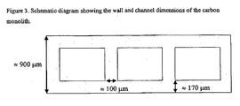
- The central, conductive gas-distributing component of the MEA, with gas flow channels, was made from porous carbon monoliths with a typical thickness of 900µm and is shown in
Figure 3 . The monoliths were made by extrusion through a single layer die using powdered phenolic resin dough. The "green" monolith was carbonised at 800°C under a CO2 atmosphere and then high-temperature (1500°C) heat-treated under a helium atmosphere. - A monolith assembly was prepared with three pieces of monolith (each approx. 1.4 cm x 5.5 cm). The monoliths were placed side by side, parallel to one another and electrically connected edge-to-edge using silver-loaded epoxy resin to create a structure approximately 4.2 x 5.5 x 0.09 cm. Copper wires were placed between the monoliths, within the silver-loaded epoxy, in order to form electrical contacts for the anode.
- The membrane used in the experiments was SH-30 supplied by Asahi Glass (Japan). Aqueous catalyst ink containing Pt on carbon and ionomer was coated on PTFE and transferred onto both sides of the membrane at 150°C, forming a catalyst coated membrane (CCM) structure. The Pt loading in these experiments was between 0.45 and 0.65 mg/cm2. The same catalyst was used on the anode and on the cathode. Toray® TGP-H-60 carbon paper with a hydrophobic micro-porous layer (containing ionomer, carbon and PTFE) was used as a gas diffusion layer substrate on the outer cathode face.
- One CCM was positioned on each side of the monolith assembly. A thermoplastic edge protection material (impermeable to H2), as described in
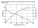
WO2006/032894 , with an open window of 3 cm x 3 cm was bonded on both sides of the CCM at 90°C. One cathode substrate and CCM was then hot-pressed to each side of the monolith assembly at 150°C. The CCM-monolith assembly was placed in the test cell and compressed with a graphite frame with an open area in order to allow free access of air. The cathodes were fully air-breathing, i.e. no outer air-blower was used. The electrical contacts to the cathodes were formed through the graphite frame, where it contacted the carbon paper. - For the actual experiments, the monolith channels were blocked at one end (dead-ended) and hydrogen was supplied to the other end from a commercially available metal hydride hydrogen storage device (Udomi, Germany). A polarisation curve is shown in
Figure 4 , together with the corresponding power density curve.
Claims (11)
- An MEA comprising:(i) a central first conductive gas diffusion substrate having a first face and a second face;(ii) first and second catalyst layers each having a first and second face and wherein the first face of the first catalyst layer is in contact with the first face of the gas diffusion substrate and the first face of the second catalyst layer is in contact with the second face of the gas diffusion substrate;(iii) first and second electrolyte layers each having a first and second face and wherein the first face of the first electrolyte layer is in contact with the second face of the first catalyst layer and the first face of the second electrolyte layer is in contact with the second face of the second catalyst layer;(iv) third and fourth catalyst layers each having a first and second face and wherein the first face of the third catalyst layer is in contact with the second face of the first electrolyte layer and the first face of the fourth catalyst layer is in contact with the second face of the second electrolyte layer; and(v) first and second porous current collecting means each having a thickness of less than 400µm, and each having a first and second face and wherein the first face of the first current collecting means is in contact with the second face of the third catalyst layer and the first face of the second current collecting means is in contact with the second face of the fourth catalyst layerwherein a) the first and second catalyst layers are both anode catalyst layers and the third and fourth catalyst layer are both cathode catalyst layers, or b) the first and second catalyst layers are both cathode catalyst layers and the third and fourth catalyst layers are both anode catalyst layers.
- An MEA according to claim 1 wherein the central gas diffusion substrate is planar.
- An MEA according to claim 1 wherein the central gas diffusion substrate is tubular.
- An MEA according to any preceding claim wherein the central gas diffusion substrate is a porous conductive carbon structure.
- An MEA according to claim 4 wherein the porous conductive carbon structure is a rigid or non-rigid fibrous or particulate carbon component.
- An MEA according to claim 4 wherein the porous conductive carbon structure has integral gas distribution means.
- An MEA according to any one of claims 1 to 3 wherein the central gas diffusion substrate is a metal or graphite substrate with one or more grooves in the first and second faces of the substrate.
- An MEA according to any one of claims 1 to 3 wherein the central gas diffusion substrate comprises at least two porous conductive layers having recesses formed therein.
- An MEA according to any preceding claim wherein the current collecting means is an array, grid or mesh of conductive metal wires or may be a metal or conductive non-metal foam.
- An MEA according to any one of claims 1 to 8 wherein the current collecting means is a conventional gas diffusion substrate.
- A fuel cell incorporating one or more MEAs according to any one of the preceding claims.
Applications Claiming Priority (2)
| Application Number | Priority Date | Filing Date | Title |
|---|---|---|---|
| GBGB0617806.5A GB0617806D0 (en) | 2006-09-11 | 2006-09-11 | Fuel cell assembly |
| PCT/GB2007/050534 WO2008032115A1 (en) | 2006-09-11 | 2007-09-11 | Fuel cell assembly |
Publications (2)
| Publication Number | Publication Date |
|---|---|
| EP2070147A1 EP2070147A1 (en) | 2009-06-17 |
| EP2070147B1 true EP2070147B1 (en) | 2012-09-05 |
Family
ID=37232689
Family Applications (1)
| Application Number | Title | Priority Date | Filing Date |
|---|---|---|---|
| EP07804440A Active EP2070147B1 (en) | 2006-09-11 | 2007-09-11 | Fuel cell assembly |
Country Status (8)
| Country | Link |
|---|---|
| US (1) | US8318373B2 (en) |
| EP (1) | EP2070147B1 (en) |
| JP (2) | JP5766401B2 (en) |
| KR (1) | KR20090063213A (en) |
| CN (1) | CN101512819B (en) |
| CA (1) | CA2663278A1 (en) |
| GB (1) | GB0617806D0 (en) |
| WO (1) | WO2008032115A1 (en) |
Families Citing this family (9)
| Publication number | Priority date | Publication date | Assignee | Title |
|---|---|---|---|---|
| GB0711882D0 (en) | 2007-06-20 | 2007-07-25 | Johnson Matthey Plc | Catalyst layer |
| US10087536B2 (en) | 2012-06-12 | 2018-10-02 | Aquahydrex Pty Ltd | Breathable electrode and method for use in water splitting |
| CA2875882A1 (en) * | 2012-06-12 | 2013-12-19 | University Of Wollongong | Gas permeable electrodes and electrochemical cells |
| KR20160040616A (en) | 2013-07-31 | 2016-04-14 | 아쿠아하이드렉스 프로프라이어터리 리미티드 | Method and Electrochemical Cell for Managing Electrochemical Reactions |
| EP3653953A1 (en) * | 2015-03-09 | 2020-05-20 | Johnson IP Holding, LLC | Thermo-electrochemical convertor with integrated energy storage |
| WO2019065989A1 (en) | 2017-09-29 | 2019-04-04 | ホヤ レンズ タイランド リミテッド | Spectacle lens and spectacles |
| KR102189655B1 (en) | 2017-09-29 | 2020-12-14 | 호야 렌즈 타일랜드 리미티드 | Eyeglass lenses and glasses |
| EP3918112A4 (en) | 2019-02-01 | 2022-10-26 | Aquahydrex, Inc. | Electrochemical system with confined electrolyte |
| CN114628771B (en) * | 2020-12-10 | 2023-07-07 | 北京好风光储能技术有限公司 | Winding type battery |
Family Cites Families (29)
| Publication number | Priority date | Publication date | Assignee | Title |
|---|---|---|---|---|
| JPH05144444A (en) * | 1991-11-25 | 1993-06-11 | Toshiba Corp | Fuel cell and electrode manufacturing method |
| US5364711A (en) * | 1992-04-01 | 1994-11-15 | Kabushiki Kaisha Toshiba | Fuel cell |
| US5800938A (en) * | 1992-09-22 | 1998-09-01 | Tanaka Kikinzoku Kogyo K.K. | Sandwich-type solid polymer electrolyte fuel cell |
| JPH0850914A (en) * | 1994-08-08 | 1996-02-20 | Fujikura Ltd | Cylindrical layer-built fuel cell |
| GB9504713D0 (en) | 1995-03-09 | 1995-04-26 | Johnson Matthey Plc | Improved electrocatalytic material |
| US5945231A (en) * | 1996-03-26 | 1999-08-31 | California Institute Of Technology | Direct liquid-feed fuel cell with membrane electrolyte and manufacturing thereof |
| US6001500A (en) * | 1996-06-05 | 1999-12-14 | Southwest Res Inst | Cylindrical proton exchange membrane fuel cells and methods of making same |
| US6054228A (en) * | 1996-06-06 | 2000-04-25 | Lynntech, Inc. | Fuel cell system for low pressure operation |
| US5858569A (en) * | 1997-03-21 | 1999-01-12 | Plug Power L.L.C. | Low cost fuel cell stack design |
| GB9708365D0 (en) | 1997-04-25 | 1997-06-18 | Johnson Matthey Plc | Proton conducting membranes |
| US5922486A (en) | 1997-05-29 | 1999-07-13 | The Dow Chemical Company | Cosintering of multilayer stacks of solid oxide fuel cells |
| US7098163B2 (en) * | 1998-08-27 | 2006-08-29 | Cabot Corporation | Method of producing membrane electrode assemblies for use in proton exchange membrane and direct methanol fuel cells |
| GB0020051D0 (en) | 2000-08-16 | 2000-10-04 | Mat & Separations Tech Int Ltd | Improved fuel cell structure |
| US7081317B2 (en) * | 2001-03-29 | 2006-07-25 | Matsushita Electric Industrial Co., Ltd. | Polymer electrolyte thin film fuel cell and method of operating the same |
| US6756150B2 (en) | 2002-04-08 | 2004-06-29 | Plug Power Inc. | Fuel cell having a non-electrolytic layer |
| KR100450820B1 (en) | 2002-04-23 | 2004-10-01 | 삼성에스디아이 주식회사 | Air breathing direct methanol fuel cell pack |
| JP2003346867A (en) * | 2002-05-27 | 2003-12-05 | Seiko Epson Corp | Fuel cell and its manufacturing method |
| JP4781818B2 (en) * | 2003-06-24 | 2011-09-28 | 旭硝子株式会社 | Method for producing membrane electrode assembly for polymer electrolyte fuel cell |
| US20050014056A1 (en) * | 2003-07-14 | 2005-01-20 | Umicore Ag & Co. Kg | Membrane electrode unit for electrochemical equipment |
| WO2005011041A1 (en) * | 2003-07-22 | 2005-02-03 | E.I. Dupont De Nemours And Company | Process for making planar framed membrane electrode assembly arrays, and fuel cells containing the same |
| US20050079403A1 (en) | 2003-09-10 | 2005-04-14 | Hollingsworth & Vose Company | Fuel cell gas diffusion layer |
| DE10342199B4 (en) | 2003-09-13 | 2007-02-08 | Daimlerchrysler Ag | Method for producing a gas diffusion layer for a fuel cell |
| US7157178B2 (en) | 2003-11-24 | 2007-01-02 | General Motors Corporation | Proton exchange membrane fuel cell |
| GB0421254D0 (en) | 2004-09-24 | 2004-10-27 | Johnson Matthey Plc | Membrane electrode assembly |
| DE112006000121B4 (en) * | 2005-02-04 | 2013-02-21 | Toyota Jidosha Kabushiki Kaisha | Hollow-type fuel cell |
| CN100463260C (en) * | 2005-05-14 | 2009-02-18 | 鸿富锦精密工业(深圳)有限公司 | Gas diffusion electrode and mfg. method thereof |
| JP4949655B2 (en) * | 2005-08-09 | 2012-06-13 | 株式会社日立製作所 | FUEL CELL, FUEL CELL POWER SUPPLY SYSTEM, AND ELECTRONIC DEVICE USING THE SAME |
| ATE402494T1 (en) | 2005-09-06 | 2008-08-15 | Sgl Carbon Ag | ELECTRODES FOR FUEL CELLS |
| KR100659132B1 (en) * | 2006-02-07 | 2006-12-19 | 삼성에스디아이 주식회사 | A membrane electrode assembly for fuel cell, a method for preparing the same and a fuel cell comprising the same |
-
2006
- 2006-09-11 GB GBGB0617806.5A patent/GB0617806D0/en not_active Ceased
-
2007
- 2007-09-11 WO PCT/GB2007/050534 patent/WO2008032115A1/en active Application Filing
- 2007-09-11 CA CA002663278A patent/CA2663278A1/en not_active Abandoned
- 2007-09-11 EP EP07804440A patent/EP2070147B1/en active Active
- 2007-09-11 KR KR1020097004940A patent/KR20090063213A/en active Search and Examination
- 2007-09-11 CN CN2007800336148A patent/CN101512819B/en not_active Expired - Fee Related
- 2007-09-11 US US12/440,691 patent/US8318373B2/en not_active Expired - Fee Related
- 2007-09-11 JP JP2009527214A patent/JP5766401B2/en not_active Expired - Fee Related
-
2013
- 2013-09-24 JP JP2013197382A patent/JP2014038857A/en active Pending
Also Published As
| Publication number | Publication date |
|---|---|
| CN101512819A (en) | 2009-08-19 |
| GB0617806D0 (en) | 2006-10-18 |
| JP2010503167A (en) | 2010-01-28 |
| US20100009232A1 (en) | 2010-01-14 |
| JP5766401B2 (en) | 2015-08-19 |
| US8318373B2 (en) | 2012-11-27 |
| WO2008032115A1 (en) | 2008-03-20 |
| EP2070147A1 (en) | 2009-06-17 |
| CA2663278A1 (en) | 2008-03-20 |
| JP2014038857A (en) | 2014-02-27 |
| KR20090063213A (en) | 2009-06-17 |
| CN101512819B (en) | 2013-02-06 |
Similar Documents
| Publication | Publication Date | Title |
|---|---|---|
| EP2070147B1 (en) | Fuel cell assembly | |
| EP2190047B1 (en) | Reinforced solid polymer electrolyte composite membrane, membrane electrode assembly for solid polymer fuel cell, and solid polymer fuel cell | |
| EP3520161B1 (en) | Cathode electrode design for electrochemical fuel cells | |
| EP1489677A2 (en) | Method of making a membrane electrode assembly for electrochemical fuel cells | |
| JP2008503852A (en) | Fuel cell system | |
| JP2004006369A (en) | Method for manufacturing membrane electrode assembly using membrane coated with catalyst | |
| EP2827418B1 (en) | Electrode assembly for solid polymer fuel cell | |
| WO2004001884A1 (en) | Fuel cell, electrode for fuel cell and method for producing them | |
| KR101640731B1 (en) | Fuel cell system | |
| EP2612390B1 (en) | Assembly for reversible fuel cell | |
| EP2519989B1 (en) | Performance enhancing layers for fuel cells | |
| US20090023032A1 (en) | Electrode for fuel cell, electrolyte-dispersed solution for forming electrode, method of producing the solution, and polymer electrolyte fuel cell | |
| WO2007048612A2 (en) | Membrane electrode assemblies for dmfc having catalyst concentration gradient | |
| EP1749322B1 (en) | Anode structure for fuel cell | |
| US20060240311A1 (en) | Membrane-electrode unit for direct methanol fuel cells and method for the production thereof | |
| JP5126812B2 (en) | Direct oxidation fuel cell | |
| JP5413056B2 (en) | COOLING LAYER FOR FUEL CELL, METHOD FOR PRODUCING THE SAME, AND FUEL CELL USING THE SAME | |
| JP2009283350A (en) | Power generator and fuel cell | |
| JP5583276B2 (en) | Direct oxidation fuel cell | |
| JP2009277465A (en) | Polymer electrolyte type fuel cell stack | |
| JP2006216404A (en) | Fuel cell | |
| JP2006066209A (en) | Direct methanol type fuel cell | |
| WO2008007136A1 (en) | Membrane electrode assembly for direct methanol fuel cell | |
| CN116897449A (en) | Method for manufacturing catalyst layer for fuel cell | |
| Baglio et al. | Status of technology and perspectives for portable applications of direct methanol fuel cells |
Legal Events
| Date | Code | Title | Description |
|---|---|---|---|
| PUAI | Public reference made under article 153(3) epc to a published international application that has entered the european phase |
Free format text: ORIGINAL CODE: 0009012 |
|
| 17P | Request for examination filed |
Effective date: 20090219 |
|
| AK | Designated contracting states |
Kind code of ref document: A1 Designated state(s): AT BE BG CH CY CZ DE DK EE ES FI FR GB GR HU IE IS IT LI LT LU LV MC MT NL PL PT RO SE SI SK TR |
|
| AX | Request for extension of the european patent |
Extension state: AL BA HR MK RS |
|
| DAX | Request for extension of the european patent (deleted) | ||
| RBV | Designated contracting states (corrected) |
Designated state(s): DE FR GB IT NL SE |
|
| 17Q | First examination report despatched |
Effective date: 20101117 |
|
| GRAP | Despatch of communication of intention to grant a patent |
Free format text: ORIGINAL CODE: EPIDOSNIGR1 |
|
| GRAS | Grant fee paid |
Free format text: ORIGINAL CODE: EPIDOSNIGR3 |
|
| RAP1 | Party data changed (applicant data changed or rights of an application transferred) |
Owner name: JOHNSON MATTHEY PUBLIC LIMITED COMPANY |
|
| GRAA | (expected) grant |
Free format text: ORIGINAL CODE: 0009210 |
|
| AK | Designated contracting states |
Kind code of ref document: B1 Designated state(s): DE FR GB IT NL SE |
|
| REG | Reference to a national code |
Ref country code: GB Ref legal event code: FG4D |
|
| RAP2 | Party data changed (patent owner data changed or rights of a patent transferred) |
Owner name: JOHNSON MATTHEY FUEL CELLS LIMITED |
|
| REG | Reference to a national code |
Ref country code: DE Ref legal event code: R082 Ref document number: 602007025320 Country of ref document: DE Representative=s name: ANDRAE FLACH HAUG, DE |
|
| REG | Reference to a national code |
Ref country code: DE Ref legal event code: R096 Ref document number: 602007025320 Country of ref document: DE Effective date: 20121025 |
|
| REG | Reference to a national code |
Ref country code: DE Ref legal event code: R081 Ref document number: 602007025320 Country of ref document: DE Owner name: JOHNSON MATTHEY FUEL CELLS LIMITED, GB Free format text: FORMER OWNER: JOHNSON MATTHEY PUBLIC LIMITED COMPANY, LONDON, GB Effective date: 20121022 Ref country code: DE Ref legal event code: R082 Ref document number: 602007025320 Country of ref document: DE Representative=s name: ANDRAE FLACH HAUG, DE Effective date: 20121022 Ref country code: DE Ref legal event code: R082 Ref document number: 602007025320 Country of ref document: DE Representative=s name: ANDRAE WESTENDORP PATENTANWAELTE PARTNERSCHAFT, DE Effective date: 20121022 |
|
| REG | Reference to a national code |
Ref country code: NL Ref legal event code: VDEP Effective date: 20120905 |
|
| PG25 | Lapsed in a contracting state [announced via postgrant information from national office to epo] |
Ref country code: SE Free format text: LAPSE BECAUSE OF FAILURE TO SUBMIT A TRANSLATION OF THE DESCRIPTION OR TO PAY THE FEE WITHIN THE PRESCRIBED TIME-LIMIT Effective date: 20120905 |
|
| PG25 | Lapsed in a contracting state [announced via postgrant information from national office to epo] |
Ref country code: NL Free format text: LAPSE BECAUSE OF FAILURE TO SUBMIT A TRANSLATION OF THE DESCRIPTION OR TO PAY THE FEE WITHIN THE PRESCRIBED TIME-LIMIT Effective date: 20120905 |
|
| PLBE | No opposition filed within time limit |
Free format text: ORIGINAL CODE: 0009261 |
|
| STAA | Information on the status of an ep patent application or granted ep patent |
Free format text: STATUS: NO OPPOSITION FILED WITHIN TIME LIMIT |
|
| 26N | No opposition filed |
Effective date: 20130606 |
|
| PG25 | Lapsed in a contracting state [announced via postgrant information from national office to epo] |
Ref country code: IT Free format text: LAPSE BECAUSE OF FAILURE TO SUBMIT A TRANSLATION OF THE DESCRIPTION OR TO PAY THE FEE WITHIN THE PRESCRIBED TIME-LIMIT Effective date: 20120905 |
|
| REG | Reference to a national code |
Ref country code: DE Ref legal event code: R097 Ref document number: 602007025320 Country of ref document: DE Effective date: 20130606 |
|
| REG | Reference to a national code |
Ref country code: DE Ref legal event code: R082 Ref document number: 602007025320 Country of ref document: DE Representative=s name: ANDRAE WESTENDORP PATENTANWAELTE PARTNERSCHAFT, DE |
|
| REG | Reference to a national code |
Ref country code: FR Ref legal event code: PLFP Year of fee payment: 10 |
|
| REG | Reference to a national code |
Ref country code: FR Ref legal event code: PLFP Year of fee payment: 11 |
|
| PGFP | Annual fee paid to national office [announced via postgrant information from national office to epo] |
Ref country code: MC Payment date: 20170914 Year of fee payment: 11 |
|
| PGFP | Annual fee paid to national office [announced via postgrant information from national office to epo] |
Ref country code: DE Payment date: 20180821 Year of fee payment: 12 |
|
| REG | Reference to a national code |
Ref country code: DE Ref legal event code: R082 Ref document number: 602007025320 Country of ref document: DE |
|
| PG25 | Lapsed in a contracting state [announced via postgrant information from national office to epo] |
Ref country code: FR Free format text: LAPSE BECAUSE OF NON-PAYMENT OF DUE FEES Effective date: 20180930 |
|
| REG | Reference to a national code |
Ref country code: DE Ref legal event code: R119 Ref document number: 602007025320 Country of ref document: DE |
|
| PG25 | Lapsed in a contracting state [announced via postgrant information from national office to epo] |
Ref country code: DE Free format text: LAPSE BECAUSE OF NON-PAYMENT OF DUE FEES Effective date: 20200401 |
|
| PGFP | Annual fee paid to national office [announced via postgrant information from national office to epo] |
Ref country code: GB Payment date: 20220819 Year of fee payment: 16 |