KR20090003307U - Hooking type slab form-work - Google Patents
Hooking type slab form-work Download PDFInfo
- Publication number
- KR20090003307U KR20090003307U KR2020070016213U KR20070016213U KR20090003307U KR 20090003307 U KR20090003307 U KR 20090003307U KR 2020070016213 U KR2020070016213 U KR 2020070016213U KR 20070016213 U KR20070016213 U KR 20070016213U KR 20090003307 U KR20090003307 U KR 20090003307U
- Authority
- KR
- South Korea
- Prior art keywords
- deck
- slab
- panel
- deck panel
- frame
- Prior art date
Links
Images


Classifications
-
- E—FIXED CONSTRUCTIONS
- E04—BUILDING
- E04G—SCAFFOLDING; FORMS; SHUTTERING; BUILDING IMPLEMENTS OR AIDS, OR THEIR USE; HANDLING BUILDING MATERIALS ON THE SITE; REPAIRING, BREAKING-UP OR OTHER WORK ON EXISTING BUILDINGS
- E04G11/00—Forms, shutterings, or falsework for making walls, floors, ceilings, or roofs
- E04G11/36—Forms, shutterings, or falsework for making walls, floors, ceilings, or roofs for floors, ceilings, or roofs of plane or curved surfaces end formpanels for floor shutterings
- E04G11/38—Forms, shutterings, or falsework for making walls, floors, ceilings, or roofs for floors, ceilings, or roofs of plane or curved surfaces end formpanels for floor shutterings for plane ceilings of concrete
-
- E—FIXED CONSTRUCTIONS
- E04—BUILDING
- E04G—SCAFFOLDING; FORMS; SHUTTERING; BUILDING IMPLEMENTS OR AIDS, OR THEIR USE; HANDLING BUILDING MATERIALS ON THE SITE; REPAIRING, BREAKING-UP OR OTHER WORK ON EXISTING BUILDINGS
- E04G11/00—Forms, shutterings, or falsework for making walls, floors, ceilings, or roofs
- E04G11/36—Forms, shutterings, or falsework for making walls, floors, ceilings, or roofs for floors, ceilings, or roofs of plane or curved surfaces end formpanels for floor shutterings
- E04G11/48—Supporting structures for shutterings or frames for floors or roofs
- E04G11/50—Girders, beams, or the like as supporting members for forms
Landscapes
- Engineering & Computer Science (AREA)
- Architecture (AREA)
- Mechanical Engineering (AREA)
- Civil Engineering (AREA)
- Structural Engineering (AREA)
- Forms Removed On Construction Sites Or Auxiliary Members Thereof (AREA)
Abstract
본 고안은 고층형 아파트, 주상복합 및 상업용 건물의 콘크리트 구조물 공사에 사용되는 알루미늄 거푸집 시스템의 슬라브 거푸집 시공 방법에 관한 것으로서, 좀 더 구체적으로 기존의 알루미늄 거푸집의 슬라브 부재를 조립 시 필요한 핀 체결을 최소화하기 위해 벽체판넬과 데크판넬을 연결하는 슬라브코너와 데크판넬과 데크판넬 사이의 데크빔에 고정홈을 형성하고 데크판넬과 데크빔의 슬라브코너 연결부에 고정홈에 맞는 걸이를 형성하여 걸이형으로 슬라브 부재 조립이 가능할 뿐 아니라 좀 더 정밀한 조립이 요구될 시 기존에 사용되던 핀 체결 병행이 가능하도록 하여 슬라브 부재 간 핀 체결, 해체 최소화에 따른 시공 작업량의 감소 및 핀 체결,해체 시 발생하는 금속 간 마찰 및 타격음을 최소화하도록 한 것이다. The present invention relates to a slab formwork method of aluminum formwork system used in the construction of concrete structures of high-rise apartments, residential complexes and commercial buildings, and more specifically, to minimize the pin fastening required when assembling slab members of the existing aluminum formwork. To make a slab corner that connects the wall panel and the deck panel, and to form a fixed groove in the deck beam between the deck panel and the deck panel, and to form a hook that fits the fixed groove in the slab corner connection of the deck panel and the deck beam, In addition to the assembly of the members, when more precise assembly is required, it is possible to perform parallel pin fastening, which reduces the amount of construction work due to pin fastening between slab members and minimization of dismantling and friction between metals during pin fastening and dismantling. And to minimize the hitting sound.
알루미늄거푸집, 벽체판넬, 데크판넬, 슬라브코너, 데크빔 Aluminum formwork, wall panel, deck panel, slab corner, deck beam
Description
본 고안은 콘크리트 구조물 공사용 알루미늄 거푸집 시스템의 슬라브 거푸집 시공 방법에 관한 것으로, 상세하게는 기존의 알루미늄 거푸집의 슬라브 부재 조립 시 필요한 핀 체결을 최소화하기 위해 벽체판넬과 데크판넬을 연결하는 슬라브코너와 데크판넬과 데크판넬 사이의 데크빔에 고정홈을 형성하고 데크판넬과 데크빔의 슬라브코너 연결부에 고정홈에 맞는 걸이를 형성하여 걸이형으로 슬라브 부재 조립이 가능할 뿐 아니라 좀 더 정밀한 조립이 요구될 시 기존의 핀 체결 병행이 가능하도록 하여, 슬라브 부재 간 핀 체결, 해체의 최소화에 따른 작업인원의 감소 및 핀 체결, 해체 시 발생하는 소음을 최소화하는 방법에 관한 것이다. The present invention relates to a slab formwork construction method of aluminum formwork system for concrete structure construction, in detail, slab corner and deck panel connecting the wall panel and the deck panel to minimize the pin fastening required when assembling the slab member of the existing aluminum formwork Forming a groove in the deck beam between the deck panel and the deck panel and forming a hook to fit the fixing groove at the slab corner connection between the deck panel and the deck beam allows the slab member to be assembled in a hook type, and when more precise assembly is required It is possible to parallelize the pin fastening, reducing the number of workers due to pin fastening between the slab members, minimization of dismantling and pin fastening, and a method of minimizing noise generated during dismantling.
아파트, 주상복합건물 등의 철근 콘크리트 공사를 수행하기 위해 콘크리트 타설용 거푸집이 사용되어야 하는데, 종래에는 철재 프레임에 합판재를 사용한 벽체 거푸집과 합판과 멍애,장선용 각목으로 슬라브 거푸집을 만들고 동바리로 슬라브 거푸집을 지탱되도록 한 다음 그 내부로 콘크리트를 타설하고 콘크리트가 양생되면 거푸집을 해체하는 방법을 사용하였다.Concrete reinforcement formwork should be used to perform reinforced concrete construction of apartments, residential complexes, etc.In the past, wall formwork using plywood for steel frames, slab formwork made of plywood, yoke, and joists are made of slabs. After the formwork was supported, concrete was poured into it and the form was dismantled when the concrete was cured.
그러나 위 종래의 방법은, 거푸집을 구성하기 위한 합판과 각목의 현장 가공이 많고 거푸집 자체의 강성이 약해 추가적인 수직, 수평 보강대를 설치하는데 많은 시 간과 인원이 소요되는데 반해 정밀성이 떨어져 후속공정이 많으며 합판과 각목은 단시간 내에 내구력이 상실되어 폐자재 발생 및 교체 작업이 빈번하여 작업능률이 저조하며 추가 보강작업의 질에 따라 거푸집 일부가 타설 중 터져 안전사고가 발생되는 등의 여러 가지 단점과 문제점이 많았다.However, in the conventional method, the plywood and lumber processing for forming the formwork is much in situ, and the rigidity of the formwork itself is weak, which requires a lot of time and personnel to install additional vertical and horizontal reinforcing bars, whereas the precision is poor and there are many subsequent processes. There were many shortcomings and problems such as the loss of durability in a short time, frequent waste material generation and replacement work, and low work efficiency, and safety accidents caused by parting of the formwork while it was being poured, depending on the quality of additional reinforcement work. .
이러한 종래의 거푸집 공사에서 비롯된 단점과 문제점을 해소키 위해 근래에 나온 거푸집 기술로서는 알루미늄 거푸집이 대표적인 예로 꼽힌다.In order to solve the disadvantages and problems caused by the conventional formwork, aluminum formwork is regarded as a representative example.
알루미늄거푸집은 알루미늄 압출재를 이용해 자체의 중량이 가볍고 전량 공장에서 제작하여 현장가공 없이 조립으로 설치 가능하여 작업성과 품질이 월등 할 뿐만 아니라 시트,프레임,보강대등 전 구성요소를 알루미늄 용접 부착하여 견고성 좋아 반복사용 횟수가 높아 비교적 저렴한 가격에 공급이 가능해 현재 아파트, 주상복합 등의 철근 콘크리트 공사에 보편적으로 사용되고 있다.The aluminum formwork is made of aluminum extruded material, which is light in weight and manufactured in the factory, and can be installed by assembly without on-site processing. It is excellent in workability and quality. It is widely used in reinforced concrete construction such as apartments and residential complexes because it can be supplied at a relatively low price due to its high number of uses.
상기와 같은 알루미늄 거푸집은 벽체거푸집 간격 유지위한 프렛타이(Flat Tie)와 거푸집간 조립 및 해체가 용이한 둥근핀(Stub Pin), 쇄기핀(Wedge Pin)을 조합시겨 사용하며, 도 4에서와 같이 수직벽체을 이루는 벽체판넬(WP, Wall Panel)을 선행 조립 후 벽체판넬(WP)의 상단부에 슬라브코너(SC, Slab Corner)를 설치하고 데크판넬(DP, Deck Panel)을 지지하기 위한 데크빔(DB, Deck Beam)을 수직 방향으로 지지하기 위한 동바리헤드(SH, Support Head)와 동바리(S, SUPPORT)를 조립하여 격자형으로 세운 후 그 사이에 데크판넬(DP)를 조립으로 설치완료 된다.Aluminum dies as described above are used in combination with a flat pin (Slat Pin), Wedge Pin (Wedge Pin) easy to assemble and dismantle between the molds to maintain the wall formwork spacing, and in Figure 4 After assembling the wall panel (WP, Wall Panel) that forms a vertical wall like this, the deck beam for installing the slab corner (SC, Slab Corner) on the top of the wall panel (WP) and supporting the deck panel (DP) ( After assembling the support head (SH) and the support (S, SUPPORT) to support the DB, Deck Beam in the vertical direction, it is set up in a lattice shape and the deck panel (DP) is installed by assembling in between.
이와 같이 시공 방법은 종래의 방식과 비교하면 많은 장점이 있으나 모든 부재가 공장 제작되어 현장 조립되기 위해 자재 종수와 수량의 과대로 이는 다음과 같은 문제점을 내포하고 있는 것이었다.As described above, the construction method has many advantages compared to the conventional method, but the excessive number of materials and quantity for all the members to be manufactured in the factory and assembled in the field has the following problems.
모든 알루미늄 거푸집 부재를 일일이 체결용 핀에 의해 결합이 필요하여 핀 체결, 해체에 많은 작업량이 소모되고 핀의 체결 및 해체 시 발생하는 금속 간의 마찰음 및 타격음의 소음 발생이 심하며, 특히 데크빔(DB), 데크판넬(DP)의 슬라브 부재는 벽체 대비 콘크리트 하중이 크지 않고 하중을 동바리(S)로 전달하는 역할로 전 슬라브 부재에 대한 핀 체결은 필요성능 대비 과잉작업이라 할 수 있다. All aluminum formwork members need to be joined together by fastening pins, which consumes a large amount of work for pin fastening and dismantling, and generates a lot of noises between friction and impact noise between metals during fastening and dismantling of pins, especially deck beam (DB). , The slab member of the deck panel (DP) is not a large concrete load compared to the wall and transfers the load to the copper club (S), the pin fastening for all the slab members can be said to be an excess of the necessity performance.
본 고안은 상기와 같은 종래의 제반 문제점을 해결 보완하기 위하여 안출된 것으로, 그 목적은 데크판넬과 데크빔을 설치 시 하부 지지부재인 데크빔과 슬라브코너의 고정홈에 걸이 방식으로 조립할 수 있도록 하고 기존 핀체결을 최소화 하는 방법을 제공함에 있는 것이다.The present invention has been devised to solve the above-mentioned conventional problems, its purpose is to be assembled to the fixing grooves of the deck beam and slab corners of the lower support member when the deck panel and deck beam is installed It is to provide a way to minimize the existing pin fastening.
상기와 같은 목적을 달성하기 위하여, 본 고안은 슬라브코너와 데크빔 부재에 걸이를 위한 고정홈을 형성하고 데크판넬 사면과 데크빔 끝단에 고정홈에 맞는 걸이를 형성토록 한 것이다.In order to achieve the above object, the present invention is to form a fixing groove for the hook on the slab corner and the deck beam member and to form a hook to fit the fixing groove on the deck panel slope and the deck beam end.
이상과 같은 본 고안은 데크빔과 데크판넬을 걸이형으로 설치 가능하며 일부 노출부의 정밀시공부위 및 비규격 위치를 맞추기 위한 필수적인 핀 체결 이외의 핀 체결 작업을 최소화 하여 설치 시 작업량, 작업시간 감소가 가능할 뿐만 아니라 해체 시 또한 핀 제거 작업 감소가 가능하여 작업량 감소와 공기 단축의 이점을 얻을 수 있으며 부수적으로 핀 체결 시 발생하는 소음 발생을 줄여 보다 쾌적한 작업환경 조성에 효과가 있고 콘크리트 타설 시 발생하는 진동에 의한 핀 풀림이 발생하더라도 걸이에 의한 고정으로 안전성 또한 확보가 가능하다.The present invention can be installed on the deck beam and the deck panel as a hook type, and the amount of work and time is reduced during installation by minimizing the pin fastening work other than the essential pin fastening for aligning the precision construction site and non-standard position of some exposed parts. Not only is it possible to dismantle, but also it is possible to reduce the work of removing the pin, which can reduce the amount of work and shorten the air.In addition, it is effective in creating a more pleasant work environment by reducing the noise generated when tightening the pin. Even if the pin is loosened by the hook, it is possible to secure safety by fixing by the hook.
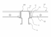
알루미늄 거푸집을 설치 시 먼저 벽체판넬(WP)을 설치한 후에 벽체판넬(WP) 상부에 슬라브코너(SC)의 벽체판넬부착면(33)에 핀결합하고 도 5의 조립 예시도와 같이 슬라브코너(SC) 수평면의 이중고정홈(34)에 동바리헤드(SH), 동바리(S), 다른 데크빔(DB'')과 빔바(BB)로 조립된 데크빔 세트의 양단의 슬라브코너용 걸이(14)를 이용해 걸이형식으로 설치가 가능하고 이는 도 6의 기존의 조립 예시도처럼 데크빔(DB)은 슬라브코너(SC)와 직접 체결 없이 슬라브코너(SC)와 데크빔(DB)에 접하는 데크판넬(DP)에 각각 핀체결 되는 방식으로, 데크빔(DB)을 설치하기 위해 슬라브코너(SC)에 접한 데크판넬(DP)을 동시에 설치하여야 하는 불편함을 개선할 수 있다. 상기와 같이 데크빔(DB)을 벽체와 벽체사이에 설치한 후 도 7의 단면 예시와 같이 데크빔(DB) 사이에 데크판넬(DP)을 데크빔(DB)의 고정홈(12)에 데크판넬(DP)의 프레임(21,22)을 걸이형식으로 설치 가능하며, 이는 기존의 도 8의 예시도 경우 종래의 데크빔(DB')에는 수직방향의 지지턱(12')가 있으나 수평방향은 핀 체결로 고정이 가능한데 반해 기존 수직방향 지지턱(12')에 수평 고정용 턱을 추가하여 고리 형상의 고정홈(12)을 형성하여 데크판넬(DP)의 프레임(21,22)을 수직수평으로 고정이 가능하고 또 이를 위해 데크판넬(DP) 프레임 모서리 하단부를 고정홈(12)에 프레임을 걸 수 있게 고정홈(12) 높이 및 프레임 두께를 고려하여 걸이용 모따기(23) 하고 판넬의 휨 방지와 걸이 프레임에 가해지는 하중을 분산 및 시트(24)보강 하기 위해 가로 보강대(25) 및 세로 보강대(26)를 부착하여 제작하고, 이와 같은 데크빔(DB)과 데크판넬(DP) 의 설치,해체 과정은 도 9의 예시도를 참조할 수 있다. When installing the aluminum formwork, first install the wall panel (WP) and then pin the wall
콘크리트 타설 후 탈형 시 먼저 벽체판넬(WP)이 해체되고 데크판넬(DP)을 해체하기 위하여 고정홈(12)이 있는 데크빔(DB)을 해체시키고 데크판넬(DP)을 제거하며 이는 도 9의 예시도를 참조할수 있으며, 단 슬라브코너(SC)는 수평슬라브면(31)과 수직벽면(32)에 길이 방향으로 끼어 있는 형태로 탈형이 쉽지 않아 연결된 데크판넬(DP) 및 데크빔(DB)이 선행하여 탈형되어야 하나 슬라브코너(SC)에 형성된 고정홈의 턱(35)으로 인해 탈형이 원활히 이루어지기 힘들며 이를 해결하기 위해 슬라브코너의 고정홈의 안쪽으로 다시 하부홈을 형성시켜 이중고정홈(34)를 형성해 탈형 시 도 10의 해체 예시도와 같은 단계로 데크판넬(DP)에 힘을 가해 걸이용 프레임(21,22)을 하부홈으로 유도하여 데크빔(DB) 및 데크판넬(DP)의 해체를 가능하도록 하였다. When demoulding after concrete pouring, the wall panel WP is first dismantled and the deck beam DB having the
상기와 같이 걸이 방식의 적용은 건설 현장의 여건상 시공오차로 인해 걸이 형식의 부재 간 상하 편차와 고정홈(12,34)을 따라 길이방향 이동이 가능함에 따라 부재가 정위치에 있지 않을 시 마지막 데크판넬(DP) 설치공간 확보 어려움 및 비규격 교차 부위의 정확한 위치 잡기, 노출 콘크리트의 경우 품질확보 등의 문제 발생 가능성을 배제할 수 없어 이를 방지하기 위해 기존 알루미늄 거푸집에 사용되는 핀 체결용 홀(H)을 슬라브코너(SC), 데크빔(DB), 데크판넬(DP)의 프레임에 가공하여 필요에 따라 핀체결로 시공 정밀성을 보완하도록 하였다. As described above, the application of the hook method is the last time when the member is not in the correct position due to the vertical deviation between the hook-type members and the longitudinal movement along the
상기의 데크빔(DB)과 슬라브코너(SC)에 적용된 고정홈(12,34)은 작업성 및 내구성 향상을 위하여 형상 및 두께를 변경할 수 있으며, 특히 본 고안은 최대의 효과가 기대되는 알루미늄 거푸집을 기준으로 작성하였으며 스틸 거푸집 및 합판과 스틸 프레임 거푸집, 합판과 알루미늄 프레임 거푸집 등 다양한 소재의 거푸집 또한 적용 가능하다.
도 1은 본 고안에 따른 데크빔을 보이는 사시도. 1 is a perspective view showing a deck beam according to the present invention.
도 2는 본 고안에 따른 데크판넬을 보이는 사시도. Figure 2 is a perspective view of the deck panel according to the present invention.
도 3은 본 고안에 따른 슬라브코너를 보이는 사시도. Figure 3 is a perspective view showing a slab corner according to the present invention.
도 4는 본 고안에 따른 조립 구성을 보이는 사시도. Figure 4 is a perspective view showing the assembly configuration according to the present invention.
도 5는 본 고안에 따른 데크빔과 슬라브코너의 조립 단면 예시도. 5 is an exemplary cross-sectional view of the deck beam and the slab corner according to the present invention.
도 6은 기존의 데크빔과 슬라브코너의 조립 단면 예시도. 6 is an exemplary cross-sectional view of the existing deck beam and slab corners.
도 7은 본 고안에 따른 데크판넬과 데크빔의 조립 단면 예시도. Figure 7 is an exemplary cross-sectional view of the deck panel and the deck beam according to the present invention.
도 8은 기존의 데크판넬과 데크빔의 조립 단면 예시도. 8 is an exemplary cross-sectional view of the existing deck panel and deck beam.
도 9는 본 고안에 따른 데크빔과 데크판넬 설치,해체 예시도. 9 is a deck beam and deck panel installation, disassembly example according to the present invention.
도 10는 본 고안에 따른 슬라브 코너와 데크판넬 해체 예시도. 10 is a view illustrating the slab corner and deck panel dismantling according to the present invention.
도면의 주요부분에 대한 부호의 설명 Explanation of symbols for main parts of the drawings
11: 동바리헤드 연결부 12: 고정홈 13: 데크판넬 부착면 11: Copper head connection part 12: Fixing groove 13: Deck panel mounting surface
14: 슬라브코너용 걸이 21: 가로프레임 22: 세로프레임 14: hanger for slab corner 21: horizontal frame 22: vertical frame
23: 걸이용 모따기 24: 시트 25: 가로보강대 23: Chamfer for hanger 24: Sheet 25: Horizontal reinforcing bar
26: 세로보강대 31: 수평슬라브면 32: 수직벽체면 26: longitudinal reinforcement 31: horizontal slab surface 32: vertical wall surface
33: 벽체판넬 부착면 34: 이중고정홈 35: 고정홈 턱 33: Wall panel mounting surface 34: Double fixing groove 35: Fixing groove jaw
P: 체결용 핀 C: 양생된 콘크리트 H: 체결용 홀(Hole) P: Fastening pin C: Cured concrete H: Fastening hole
Claims (3)
Priority Applications (1)
| Application Number | Priority Date | Filing Date | Title |
|---|---|---|---|
| KR2020070016213U KR20090003307U (en) | 2007-10-05 | 2007-10-05 | Hooking type slab form-work |
Applications Claiming Priority (1)
| Application Number | Priority Date | Filing Date | Title |
|---|---|---|---|
| KR2020070016213U KR20090003307U (en) | 2007-10-05 | 2007-10-05 | Hooking type slab form-work |
Publications (1)
| Publication Number | Publication Date |
|---|---|
| KR20090003307U true KR20090003307U (en) | 2009-04-09 |
Family
ID=41320741
Family Applications (1)
| Application Number | Title | Priority Date | Filing Date |
|---|---|---|---|
| KR2020070016213U KR20090003307U (en) | 2007-10-05 | 2007-10-05 | Hooking type slab form-work |
Country Status (1)
| Country | Link |
|---|---|
| KR (1) | KR20090003307U (en) |
Cited By (9)
| Publication number | Priority date | Publication date | Assignee | Title |
|---|---|---|---|---|
| KR101142879B1 (en) * | 2010-05-31 | 2012-05-10 | (주)거혁산업 | Support structure for slab foam panel |
| CN103216087A (en) * | 2013-04-09 | 2013-07-24 | 佛山市广成铝业有限公司 | Bilateral self-bearing building template system |
| CN103866975A (en) * | 2014-02-28 | 2014-06-18 | 苏鸿飞 | Building formwork assembly method and used aluminium formwork connector |
| FR3012492A1 (en) * | 2013-10-25 | 2015-05-01 | Alphi | MODULAR SUPPORT STRUCTURE |
| CN107090974A (en) * | 2017-07-03 | 2017-08-25 | 北京城建六建设集团有限公司 | A kind of top plate Quick Release support system and its construction method |
| KR20180029378A (en) * | 2016-09-12 | 2018-03-21 | 서보산업 주식회사 | Low noise concrete mold assembly, and method for constructing and removing this same |
| KR102534830B1 (en) * | 2022-06-24 | 2023-05-26 | 김재성 | PIT floor multi support system and PIT floor construction method using the same |
| KR102588569B1 (en) * | 2023-02-07 | 2023-10-12 | 윤병주 | Wall in-corner and wall and ceiling corner formwork panel |
| KR20230168166A (en) * | 2022-06-03 | 2023-12-12 | 고정숙 | Incorner coupling equipment for construction mold |
-
2007
- 2007-10-05 KR KR2020070016213U patent/KR20090003307U/en not_active Application Discontinuation
Cited By (12)
| Publication number | Priority date | Publication date | Assignee | Title |
|---|---|---|---|---|
| KR101142879B1 (en) * | 2010-05-31 | 2012-05-10 | (주)거혁산업 | Support structure for slab foam panel |
| CN103216087A (en) * | 2013-04-09 | 2013-07-24 | 佛山市广成铝业有限公司 | Bilateral self-bearing building template system |
| CN103216087B (en) * | 2013-04-09 | 2016-02-03 | 佛山市广亚铝模科技有限公司 | A kind of two-way self-bearing type construction formwork system |
| FR3012492A1 (en) * | 2013-10-25 | 2015-05-01 | Alphi | MODULAR SUPPORT STRUCTURE |
| CN103866975A (en) * | 2014-02-28 | 2014-06-18 | 苏鸿飞 | Building formwork assembly method and used aluminium formwork connector |
| CN103866975B (en) * | 2014-02-28 | 2016-02-03 | 苏鸿飞 | The mounting method of construction formwork and the aluminum alloy pattern plate connector used |
| KR20180029378A (en) * | 2016-09-12 | 2018-03-21 | 서보산업 주식회사 | Low noise concrete mold assembly, and method for constructing and removing this same |
| CN107090974A (en) * | 2017-07-03 | 2017-08-25 | 北京城建六建设集团有限公司 | A kind of top plate Quick Release support system and its construction method |
| CN107090974B (en) * | 2017-07-03 | 2023-09-05 | 北京城建六建设集团有限公司 | Roof quick-release supporting system and construction method thereof |
| KR20230168166A (en) * | 2022-06-03 | 2023-12-12 | 고정숙 | Incorner coupling equipment for construction mold |
| KR102534830B1 (en) * | 2022-06-24 | 2023-05-26 | 김재성 | PIT floor multi support system and PIT floor construction method using the same |
| KR102588569B1 (en) * | 2023-02-07 | 2023-10-12 | 윤병주 | Wall in-corner and wall and ceiling corner formwork panel |
Similar Documents
| Publication | Publication Date | Title |
|---|---|---|
| KR20090003307U (en) | Hooking type slab form-work | |
| KR20190041785A (en) | Combination structure of permanent concrete form and prefabricated steel assembly for steel composite concrete | |
| KR101490808B1 (en) | Prefabricated steel frame equipped with removable concrete form for composite member of steel and concrete | |
| KR20180045140A (en) | The structure of non-binding dismantling formwork beams and deck plates without the need to secure jobs | |
| KR101432260B1 (en) | Steel-exposed type steel framed reinforced concrete pillar | |
| KR20100123232A (en) | Mold panel easy construction and dismantle | |
| KR101594974B1 (en) | Hybrid beam | |
| KR101018411B1 (en) | Beam side form for deep deck and joint structure and construction method of reinforce concrete beam and slab for deep deck floor system thereof | |
| KR20100123231A (en) | Slid type mold panel easy construction and dismantle | |
| KR20220022664A (en) | Cross joint for fixing formwork | |
| CN115324341B (en) | Construction method of steel-concrete composite beam | |
| KR200414945Y1 (en) | A slab panel for euro form of deck panel construct | |
| KR200357642Y1 (en) | Reinforcement structure of inconner panel | |
| KR20090007085A (en) | Form with reinforced bar, manufacturing method thereof and construction method using the same | |
| CN111706005A (en) | Integrated reinforcing steel bar formwork-free cast-in-place concrete beam | |
| KR200405361Y1 (en) | Sliding End Panel for forms | |
| KR101078292B1 (en) | Concrete slab mold assembly and method for constructing slab | |
| KR100746728B1 (en) | Form system for structuring concrete | |
| KR200411037Y1 (en) | Form system for structuring concrete | |
| CN214658855U (en) | Supporting system for building template | |
| KR100339440B1 (en) | Construction method using mold equipped with shape steel and plywood | |
| CN113107189B (en) | Aluminum template structure | |
| KR200391961Y1 (en) | Finish panal for forms | |
| KR20190001131U (en) | Structure of a single line truss girder integrating insulation | |
| KR100471178B1 (en) | Form for constructing concrete structure |
Legal Events
| Date | Code | Title | Description |
|---|---|---|---|
| A201 | Request for examination | ||
| E902 | Notification of reason for refusal | ||
| E601 | Decision to refuse application | ||
| E601 | Decision to refuse application |