KR20080109813A - Lithographic projection apparatus, gas purging method, device manufacturing method and purge gas supply system - Google Patents
Lithographic projection apparatus, gas purging method, device manufacturing method and purge gas supply system Download PDFInfo
- Publication number
- KR20080109813A KR20080109813A KR1020087024264A KR20087024264A KR20080109813A KR 20080109813 A KR20080109813 A KR 20080109813A KR 1020087024264 A KR1020087024264 A KR 1020087024264A KR 20087024264 A KR20087024264 A KR 20087024264A KR 20080109813 A KR20080109813 A KR 20080109813A
- Authority
- KR
- South Korea
- Prior art keywords
- purge gas
- gas mixture
- liquid
- pressure
- temperature
- Prior art date
Links
Images


Classifications
-
- G—PHYSICS
- G03—PHOTOGRAPHY; CINEMATOGRAPHY; ANALOGOUS TECHNIQUES USING WAVES OTHER THAN OPTICAL WAVES; ELECTROGRAPHY; HOLOGRAPHY
- G03F—PHOTOMECHANICAL PRODUCTION OF TEXTURED OR PATTERNED SURFACES, e.g. FOR PRINTING, FOR PROCESSING OF SEMICONDUCTOR DEVICES; MATERIALS THEREFOR; ORIGINALS THEREFOR; APPARATUS SPECIALLY ADAPTED THEREFOR
- G03F7/00—Photomechanical, e.g. photolithographic, production of textured or patterned surfaces, e.g. printing surfaces; Materials therefor, e.g. comprising photoresists; Apparatus specially adapted therefor
- G03F7/70—Microphotolithographic exposure; Apparatus therefor
- G03F7/708—Construction of apparatus, e.g. environment aspects, hygiene aspects or materials
- G03F7/70908—Hygiene, e.g. preventing apparatus pollution, mitigating effect of pollution or removing pollutants from apparatus
- G03F7/70933—Purge, e.g. exchanging fluid or gas to remove pollutants
-
- G—PHYSICS
- G02—OPTICS
- G02B—OPTICAL ELEMENTS, SYSTEMS OR APPARATUS
- G02B27/00—Optical systems or apparatus not provided for by any of the groups G02B1/00 - G02B26/00, G02B30/00
-
- G—PHYSICS
- G02—OPTICS
- G02B—OPTICAL ELEMENTS, SYSTEMS OR APPARATUS
- G02B27/00—Optical systems or apparatus not provided for by any of the groups G02B1/00 - G02B26/00, G02B30/00
- G02B27/0006—Optical systems or apparatus not provided for by any of the groups G02B1/00 - G02B26/00, G02B30/00 with means to keep optical surfaces clean, e.g. by preventing or removing dirt, stains, contamination, condensation
Landscapes
- Physics & Mathematics (AREA)
- General Physics & Mathematics (AREA)
- Health & Medical Sciences (AREA)
- Epidemiology (AREA)
- Public Health (AREA)
- Optics & Photonics (AREA)
- Life Sciences & Earth Sciences (AREA)
- Atmospheric Sciences (AREA)
- Engineering & Computer Science (AREA)
- Environmental & Geological Engineering (AREA)
- Exposure And Positioning Against Photoresist Photosensitive Materials (AREA)
- Exposure Of Semiconductors, Excluding Electron Or Ion Beam Exposure (AREA)
Abstract
Description
본 출원은 2006년 4월 3일자로 출원된 미국 출원 제11/396,823호의 계속 출원으로서 그 이득을 주장하고, 2003년 7월 21일자로 출원된 미국 출원 제10/623,180호의 일부 계속 출원으로서 그 이득을 주장하고, 2004년 7월 21일자로 출원된 국제 특허 출원 제PCT/US2004/023490호의 일부 계속 출원으로서 그 이득을 주장하며, 2004년 7월 21일자로 출원된 미국 출원 제10/565,486호의 일부 계속 출원으로서 그 이득을 주장하고, 이들 출원들의 내용은 그 전문이 참조로 본 명세서에 통합되어 있다.This application claims the benefit as a continuing application of US Application No. 11 / 396,823, filed April 3, 2006, and as a partial continuing application of US Application No. 10 / 623,180, filed July 21, 2003. , Claiming benefit as part of a continuing application of International Patent Application No. PCT / US2004 / 023490, filed July 21, 2004, and part of US Application No. 10 / 565,486, filed July 21, 2004 Claiming the benefits as a continuing application, the contents of these applications are incorporated herein by reference in their entirety.
장치의 대부분이 진공에서 동작하는 경우라도, 리소그래픽 투사 장치 내에 존재하는 구성요소의 표면은 사용 동안 점진적으로 오염될 수 있다. 특히, 이런 오염이 광학적 구성요소의 광학 특성에 영향을 주기 때문에, 거울 같은 리소그래픽 투사 장치 내의 광학적 구성요소의 오염은 장치의 성능에 부정적인 영향을 갖는다.Even if the majority of the device is operating in vacuum, the surface of the components present in the lithographic projection device may be progressively contaminated during use. In particular, since such contamination affects the optical properties of the optical component, contamination of the optical component in a lithographic projection apparatus such as a mirror has a negative effect on the performance of the apparatus.
이런 광학적 구성요소가 내부에 배치되는 리소그래픽 투사 장치의 공간을 퍼지 가스라 지칭되는 초고순도 가스로 정화(purging)함으로써 리소그래픽 투사 장치 의 광학적 구성요소의 오염이 감소될 수 있다는 것이 알려져 있다. 이 퍼지 가스는 예로서 탄화수소를 갖는 분자 오염물에 의한 표면의 오염을 방지한다.It is known that contamination of the optical components of the lithographic projection apparatus can be reduced by purging the space of the lithographic projection apparatus in which such optical components are disposed with an ultra high purity gas called purge gas. This purge gas, for example, prevents surface contamination by molecular contaminants with hydrocarbons.
이 방법의 단점은 퍼지 가스가 리소그래픽 프로세스에서 사용되는 화학제의 활성도에 부정적인 영향을 가질 수 있다는 것이다. 따라서, 리소그래픽 투사 시스템의 광학적 구성요소의 오염을 감소시키지만 리소그래픽 프로세스에 사용되는 화학제의 활성도에는 부정적인 영향을 주지 않는 개선된 퍼지 가스에 대한 필요성이 존재한다.A disadvantage of this method is that the purge gas can have a negative effect on the activity of the chemicals used in the lithographic process. Thus, there is a need for an improved purge gas that reduces contamination of the optical components of the lithographic projection system but does not adversely affect the activity of the chemicals used in the lithographic process.
본 발명의 형태는 패터닝 장치를 지지하도록 구성된 지지 구조체와 방사선 비임을 제공하도록 구성된 조명기를 포함할 수 있는 리소그래픽 투사 장치를 포함한다. 패터닝 장치는 원하는 패턴에 따라 방사선 비임을 패턴화하도록 구성된다. 기판 테이블은 기판을 보유하도록 구성된다. 투사 시스템은 기판의 타겟 부분 상에 패턴화된 비임을 투사하도록 구성된다. 적어도 하나의 퍼지 가스 공급 시스템은 리소그래픽 투사 장치의 적어도 일부에 퍼지 가스를 제공하도록 구성된다. 적어도 하나의 퍼지 가스 공급 시스템은 퍼지 가스 혼합물을 형성하도록 퍼지 가스에 증기를 추가하게 구성된 기화기를 포함하는 퍼지 가스 혼합물 발생기를 구비한다. 몇몇 형태에서, 퍼지 가스는 본질적으로 퍼지 가스와, 기화가능 액체로부터의 증기로 구성된다. 몇몇 구현예에서, 퍼지 가스 혼합물은 퍼지 가스와 기화가능 액체로부터의 증기를 포함할 수 있다. 기화가능 액체는 퍼지 가스 내에 비오염 증기를 형성하고, 혼합물은 리소그래픽 투사 장치 내의 광학 구성요소의 오염을 감소 또는 제거하면서, 기판 상의 코팅의 화학적 활성도를 유지하기 위해 사용된다. 퍼지 가스 혼합물 출구는 퍼지 가스 혼합물 발생기에 연결되고, 리소그래픽 투사 장치의 적어도 일부에 퍼지 가스 혼합물을 공급하도록 구성될 수 있다. 퍼지 가스 혼합물 발생기 내의 기화기는 퍼지 가스에 1 ppt(part per trillion)를 초과하는 오염물을 부가하지 않으면서 높은 유량으로 퍼지 가스에 증기를 추가한다. 몇몇 구현예에서, 퍼지 가스 혼합물 발생기 내의 기화기는 리소그래픽 투사 시스템 내의 광학 구성요소의 광학 특성을 열화시키는 약 1 ppb(part per billion)를 초과하는 오염물을 퍼지 가스에 부가하지 않으면서 높은 유량으로 퍼지 가스에 증기를 추가한다.Aspects of the present invention include a lithographic projection apparatus that may include a support structure configured to support a patterning device and an illuminator configured to provide a radiation beam. The patterning device is configured to pattern the radiation beam according to a desired pattern. The substrate table is configured to hold a substrate. The projection system is configured to project the patterned beam onto a target portion of the substrate. At least one purge gas supply system is configured to provide purge gas to at least a portion of the lithographic projection apparatus. At least one purge gas supply system has a purge gas mixture generator comprising a vaporizer configured to add steam to the purge gas to form a purge gas mixture. In some forms, the purge gas consists essentially of the purge gas and vapor from the vaporizable liquid. In some embodiments, the purge gas mixture may include vapor from the purge gas and the vaporizable liquid. The vaporizable liquid forms non-contaminated vapor in the purge gas, and the mixture is used to maintain the chemical activity of the coating on the substrate while reducing or eliminating contamination of the optical components in the lithographic projection apparatus. The purge gas mixture outlet is connected to the purge gas mixture generator and may be configured to supply the purge gas mixture to at least a portion of the lithographic projection apparatus. The vaporizer in the purge gas mixture generator adds steam to the purge gas at a high flow rate without adding more than 1 part per trillion of contaminants to the purge gas. In some embodiments, the vaporizer in the purge gas mixture generator purges at high flow rates without adding more than about 1 part per billion contaminants to the purge gas, which degrades the optical properties of the optical components in the lithographic projection system. Add steam to the gas.
본 발명의 태양은 개선된 리소그래픽 투사 장치, 특히, 레지스트의 현상에 영향을 주지 않으면서 퍼지 가스를 사용하여 오염물이 감소될 수 있는 리소그래픽 투사 장치를 제공하는 것이다.It is an aspect of the present invention to provide an improved lithographic projection apparatus, in particular a lithographic projection apparatus in which contaminants can be reduced using purge gas without affecting the development of the resist.
본 발명의 일 태양에 따라서, 리소그래픽 투사 장치는 패터닝 장치를 지지하도록 구성된 지지 구조체와 방사선 비임을 제공하도록 구성된 조명기를 포함한다. 패터닝 장치는 원하는 패턴에 따라 방사선 비임을 패턴화하도록 구성된다. 기판 테이블은 기판을 보유하도록 구성된다. 투사 시스템은 기판의 타겟 부분 상에 패턴화된 비임을 투사시키도록 구성된다. 적어도 하나의 퍼지 가스 공급 시스템은 리소그래픽 투사 장치의 적어도 일부에 퍼지 가스를 제공하도록 구성된다. 적어도 하나의 퍼지 가스 공급 시스템은 퍼지 가스에 습기를 추가하도록 구성된 기화기를 포함하는 퍼지 가스 혼합물 발생기를 포함할 수 있다. 퍼지 가스 혼합물 발생기는 퍼지 가스 혼합물을 발생시키도록 구성된다. 퍼지 가스 혼합물은 적어도 하나의 퍼지 가스 및 습기를 포함한다. 퍼지 가스 혼합물 출구는 퍼지 가스 혼합물 발생기에 연결되며, 리소그래픽 투사 장치의 적어도 일부에 퍼지 가스 혼합물을 공급하도록 구성된다. 따라서, 습기가 존재하며, 화학제, 예를 들어, 레지스트의 현상제의 활성도는 퍼지 가스 혼합물에 의해 영향을 받지 않는다.According to one aspect of the invention, a lithographic projection apparatus includes a support structure configured to support a patterning device and an illuminator configured to provide a radiation beam. The patterning device is configured to pattern the radiation beam according to a desired pattern. The substrate table is configured to hold a substrate. The projection system is configured to project the patterned beam onto a target portion of the substrate. At least one purge gas supply system is configured to provide purge gas to at least a portion of the lithographic projection apparatus. The at least one purge gas supply system may include a purge gas mixture generator including a vaporizer configured to add moisture to the purge gas. The purge gas mixture generator is configured to generate a purge gas mixture. The purge gas mixture includes at least one purge gas and moisture. The purge gas mixture outlet is connected to the purge gas mixture generator and is configured to supply the purge gas mixture to at least a portion of the lithographic projection apparatus. Thus, moisture is present and the activity of the chemical, for example the developer of the resist, is not affected by the purge gas mixture.
본 발명의 또 다른 태양에 따라서, 퍼지 가스 공급 시스템은 퍼지 가스에 습기를 추가하도록 구성된 가습기를 포함하는 퍼지 가스 혼합물 발생기를 포함한다. 퍼지 가스 혼합물 발생기는 퍼지 가스 출구를 포함하면서 습기와 적어도 하나의 퍼지 가스를 포함하는 퍼지 가스 혼합물을 발생시키도록 구성된다. 일 예에서, 퍼지 가스 출구는 리소그래픽 투사 장치의 적어도 일부에 퍼지 가스 혼합물을 공급하도록 구성된다. 본 발명의 일 형태에서, 퍼지 가스 혼합물은 퍼지 가스 및 습기로 구성된 조성물이며, 이 조성물은 리소그래픽 투사 장치 내의 기판 상에 패턴을 형성하도록 방사선과 상호작용하는 광학 구성요소의 광학 특성에 대한 부정적 영향을 갖는 약 1 ppb 미만의 오염물을 포함한다. According to another aspect of the invention, a purge gas supply system includes a purge gas mixture generator comprising a humidifier configured to add moisture to the purge gas. The purge gas mixture generator is configured to generate a purge gas mixture comprising a purge gas outlet and comprising moisture and at least one purge gas. In one example, the purge gas outlet is configured to supply the purge gas mixture to at least a portion of the lithographic projection apparatus. In one aspect of the invention, the purge gas mixture is a composition consisting of purge gas and moisture, which composition has a negative effect on the optical properties of the optical component interacting with the radiation to form a pattern on a substrate in the lithographic projection apparatus Having less than about 1 ppb contaminants.
양호한 구현예에서, 퍼지 가스 혼합물 공급 시스템은 퍼지 가스 소스와, 물 소스와, 퍼지 가스에 습기를 추가하도록 구성된 가습기를 구비하는 퍼지 가스 혼합물 발생기를 포함한다. 또한, 공급 시스템은 선택적으로 물이 가습기에 진입시 또는 그 이전에 가열되도록 물을 위한 가열 장치를 포함한다.In a preferred embodiment, the purge gas mixture supply system includes a purge gas mixture generator having a purge gas source, a water source, and a humidifier configured to add moisture to the purge gas. The supply system also optionally includes a heating device for the water such that the water is heated upon or before entering the humidifier.
본 발명의 일 형태에서, 기화기는 퍼지 가스 공급 시스템을 위한 가습기이며, 리소그래픽 투사 장치는 퍼지 가스 흐름을 포함하는 제1 영역과, 물을 포함하는 제2 영역을 포함하며, 제1 및 제2 영역은 기화가능 액체에 의한 액체 침투에 대해 실질적으로 내성적인 기화기의 가스 투과성 멤브레인에 의해 분리되어 있다. 더욱 바람직하게, 가습기는 제1 단부와 제2 단부를 구비하는 복수의 과불화(perfluorinated) 가스 투과성 열가소성 중공 파이버 멤브레인의 다발을 포함하며, 멤브레인은 외부면과 내부면을 가지고, 내부면은 루멘을 포함하며, 다발의 각 단부는 파이버 단부가 유체 유동에 대해 개방된 주변 과불화 열가소성 하우징을 갖는 단일체형 단부 구조체를 형성하는 액밀식 과불화 열가소성 밀봉부로 포팅(potting)된다. 하우징은 내벽 및 외벽을 구비하고, 내벽은 내벽과 중공 파이버 멤브레인 사이에 유체 유동 체적을 형성하며, 하우징은 퍼지 가스 소스에 연결된 퍼지 가스 입구 및 퍼지 가스 혼합물 출구를 포함한다. 하우징은 물 소스에 연결된 물 입구 및 물 출구를 포함하고, 퍼지 가스 입구가 다발의 제1 단부에 연결되고, 퍼지 가스 혼합물 출구는 다발의 제2 단부에 연결되거나, 물 입구가 다발의 제1 단부에 연결되고 물 출구가 다발의 제2 단부에 연결되며, 퍼지 가스 혼합물은 적어도 하나의 퍼지 가스와 습기를 포함한다.In one embodiment of the present invention, the vaporizer is a humidifier for a purge gas supply system, and the lithographic projection apparatus includes a first region containing a purge gas flow, and a second region containing water, wherein the first and second The regions are separated by a gas permeable membrane of the vaporizer which is substantially resistant to liquid penetration by the vaporizable liquid. More preferably, the humidifier comprises a bundle of a plurality of perfluorinated gas permeable thermoplastic hollow fiber membranes having a first end and a second end, the membrane having an outer surface and an inner surface, the inner surface having lumens. Each end of the bundle is potted with a liquid-tight perfluorinated thermoplastic seal that forms a monolithic end structure having a periphery perfluorinated thermoplastic housing with fiber ends open to fluid flow. The housing has an inner wall and an outer wall, the inner wall forming a fluid flow volume between the inner wall and the hollow fiber membrane, the housing including a purge gas inlet and a purge gas mixture outlet connected to the purge gas source. The housing includes a water inlet and a water outlet connected to the water source, the purge gas inlet is connected to the first end of the bundle, the purge gas mixture outlet is connected to the second end of the bundle, or the water inlet is the first end of the bundle Is connected to the second end of the bundle, and the purge gas mixture comprises at least one purge gas and moisture.
본 발명의 다른 태양에 따라서, 퍼지 가스에 증기를 추가하는 방법은 퍼직 가스에 증기를 추가하기에 충분한 기간 동안 상술한 기화기를 통해 퍼지 가스를 통과시키는 단계를 포함한다. 증기를 포함하는 퍼지 가스는 리소그래픽 투사 장치의 적어도 일부에 제공된다. 일 구현예에서, 증기는 수증기이며, 퍼지 가스에 습기를 추가함으로써 적어도 하나의 퍼지 가스와 습기를 갖는 퍼지 가스 혼합물을 생성하는 단계와, 리소그래픽 투사 장치의 적어도 일부에 퍼지 가스 혼합물을 공급하는 단계를 포함하고, 퍼지 가스 혼합물은 퍼지 가스와 습기를 포함한다. 따라서, 리소그래픽 투사 장치 내에 사용되는 화학제는 퍼지 가스에 의해 영향을 받지 않는다.According to another aspect of the invention, a method of adding steam to a purge gas includes passing the purge gas through the vaporizer described above for a period sufficient to add steam to the purge gas. A purge gas comprising vapor is provided to at least a portion of the lithographic projection apparatus. In one embodiment, the vapor is water vapor, creating a purge gas mixture having at least one purge gas and moisture by adding moisture to the purge gas, and supplying the purge gas mixture to at least a portion of the lithographic projection apparatus. And a purge gas mixture includes purge gas and moisture. Thus, the chemicals used in the lithographic projection apparatus are not affected by the purge gas.
본 발명의 다른 태양에 따라서, 장치 제조 방법은 방사선 감응성 재료의 층에 의해 적어도 부분적으로 덮여진 기판의 적어도 일부에 상술한 방법을 적용하는 단계와, 방사선 감응성 재료의 층의 타겟 부분 상에 패턴화된 방사선 비임을 투사하는 단계와, 장치 제조 방법에 사용된 구성요소의 표면 부근에 퍼지 가스 혼합물을 공급하는 단계를 포함한다.According to another aspect of the invention, a method of manufacturing a device comprises applying the method described above to at least a portion of a substrate that is at least partially covered by a layer of radiation sensitive material, and patterning on the target portion of the layer of radiation sensitive material. Projecting the irradiated beam of radiation and supplying a purge gas mixture near the surface of the components used in the device manufacturing method.
본 발명의 다른 세부사항, 태양 및 구현예가 첨부 도면을 참조로, 단지 예시로서 설명될 것이다. Other details, aspects and embodiments of the invention will now be described by way of example only with reference to the accompanying drawings.
도1은 본 발명의 형태에 따른 리소그래픽 투사 장치의 일 구현예의 예를 개략적으로 도시한다.1 schematically shows an example of one embodiment of a lithographic projection apparatus according to the form of the present invention.
도2는 본 발명의 일 구현예에 따른 리소그래픽 투사 장치의 EUV 조명 시스템 및 투사 광학장치의 측면도를 도시한다.2 shows a side view of an EUV illumination system and a projection optics of a lithographic projection apparatus according to one embodiment of the invention.
도3은 본 발명의 일 구현예에 따른 퍼지 가스 혼합물 공급 시스템의 일 예를 개략적으로 예시한다.3 schematically illustrates an example of a purge gas mixture supply system according to one embodiment of the invention.
도4는 도3의 예에 사용하기에 적합한 가습기 장치를 개략적으로 도시한다.4 schematically illustrates a humidifier device suitable for use in the example of FIG. 3.
도5는 도3의 예에 사용될 수 있는 중공 파이버 멤브레인 기화기 또는 가습기의 예시도이다.FIG. 5 is an illustration of a hollow fiber membrane vaporizer or humidifier that can be used in the example of FIG.
도6은 실시예 1에 사용된 멤브레인 접촉기 테스트 매니폴드를 도시한다.6 shows the membrane contactor test manifold used in Example 1. FIG.
도7은 초-청정 건조 공기(XCDA)를 위한 가스 크로마토그래피/불꽃 이온화 검출기(gas chromatography/flame ionization detector; GC/FID) 판독을 도시한다.FIG. 7 shows a gas chromatography / flame ionization detector (GC / FID) reading for ultra-clean dry air (XCDA).
도8은 실시예 1에 설명된 바와 같은 가습기를 통과한 XCDA를 위한 GC/FID 판독을 도시한다.FIG. 8 shows the GC / FID readout for XCDA through a humidifier as described in Example 1. FIG.
도9는 XCDA를 위한 가스 크로마토그래피/펄스 불꽃 포토메트릭 검출기(gas chromatography/pulse flame photometric detector; GC/PFPD) 판독을 도시한다. FIG. 9 shows a gas chromatography / pulse flame photometric detector (GC / PFPD) reading for XCDA.
도10은 실시예 1에 설명된 바와 같이 가습기를 통과한 XCDA를 위한 GC/PFPD 판독을 도시한다.FIG. 10 shows the GC / PFPD readout for XCDA passing through the humidifier as described in Example 1. FIG.
도11A는 퍼지 가스 혼합물의 희석을 위한 퍼지 가스의 소스를 구비하는 일 형태의 퍼지 가스 공급 시스템을 예시하며, 또한, 광학 트랩이 도시되어 있고, 도11B는 기화기 또는 가습기로부터 퍼지 가스 혼합물의 온도를 유지하기 위한 열 교환 영역과, 퍼지 가스 혼합물의 희석을 위한 퍼지 가스의 소스를 구비하는 일 형태의 퍼지 가스 공급 시스템을 예시한다. FIG. 11A illustrates one type of purge gas supply system with a source of purge gas for dilution of the purge gas mixture, and also shows an optical trap, and FIG. 11B shows the temperature of the purge gas mixture from a vaporizer or humidifier. Illustrates one form of purge gas supply system having a heat exchange area for maintenance and a source of purge gas for dilution of the purge gas mixture.
도12는 18 psig(0.124 Mpag)의 물이 기화가능 액체인 기화기로부터의 두 가지 다른 가스 출구 압력에서 포화에 대한 증기 출력을 예시하는 그래프. FIG. 12 is a graph illustrating steam output for saturation at two different gas outlet pressures from a vaporizer in which 18 psig (0.124 Mpag) of water is a vaporizable liquid.
도13A는 59 psig(0.407 Mpag)의 기화기 내의 물 같은 기화가능 액체를 위한 가스 압력과 서로 다른 유량에서 기화기로부터의 포화에 대한 증기 출력을 예시하는 그래프이고, 도13B는 기화기 내의 서로 다른 가스 압력에서 퍼지 가스 혼합물 내의 증기의 계산된 농도의 그래프이다.FIG. 13A is a graph illustrating the gas pressure for a vaporizable liquid such as water in a vaporizer of 59 psig (0.407 Mpag) and the steam output for saturation from the vaporizer at different flow rates, and FIG. 13B is at a different gas pressure in the vaporizer. It is a graph of the calculated concentration of vapor in the purge gas mixture.
도14는 함께 연결된 하나 이상의 중공 파이버 기화기로 퍼지 가스 혼합물을 생성하기 위한 장치의 예시도이다.14 is an illustration of an apparatus for producing a purge gas mixture with one or more hollow fiber vaporizers connected together.
도15는 중공 파이버 기화기를 통해 흐르는 퍼지 가스 내의 증기 농도가 기화기를 통한 퍼지 가스 유량에 실질적으로 독립적인 범위로 제어될 수 있다는 것을 예시하는 그래프이다.FIG. 15 is a graph illustrating that the vapor concentration in the purge gas flowing through the hollow fiber vaporizer can be controlled to a range substantially independent of the purge gas flow rate through the vaporizer.
본 발명의 조성 및 방법을 설명하기 전에, 본 발명은 설명된 특정 분자, 조성, 방법 또는 프로토콜에 한정되지 않는다는 것을 이해하여야 하며, 그 이유는 이들이 변할 수 있기 때문이다. 또한, 본 설명에 사용된 용어는 특정 형태 또는 구현예를 설명하기 위한 것이며, 첨부된 청구범위에 의해서만 한정되는 본 발명의 범주를 제한하기 위한 것은 아니라는 것을 이해하여야 한다.Before describing the compositions and methods of the present invention, it should be understood that the present invention is not limited to the specific molecules, compositions, methods or protocols described, as these may vary. It is also to be understood that the terminology used herein is for the purpose of describing particular forms or embodiments only, and is not intended to limit the scope of the present invention, which is limited only by the appended claims.
본 명세서 및 첨부된 청구범위에서 사용될 때, 단수형 용어 "일" 및 "그"는 내용상 달리 명시되지 않는 한, 복수에 대한 언급을 포함하는 것임을 주의하여야 한다. 따라서, 예로서, "중공 화이버"라는 기재는 본 기술 분야의 숙련자들에게 공지된 하나 이상의 중공 화이버와 그 등가체들 등을 지칭한다. 달리 명시하지 않는 한, 본 명세서에 사용되는 모든 기술적 및 과학적 용어는 본 기술의 통상적인 지식을 가진 자가 일반적으로 이해하는 바와 동일한 의미를 갖는다. 비록 본 명세서에 설명된 것들과 유사하거나 대등한 임의의 방법 및 재료가 본 발명의 구현예의 실시 또는 시험에 사용될 수 있지만, 이제, 양호한 방법, 장치 및 재료를 설명한다. 본 명세서에 언급된 모든 공보는 참조로 통합되어 있다. 본 명세서의 어떠한 내용도 본 발명이 종래의 발명에 의해 이런 기재를 예상할 자격이 없다는 허가로서 해석되지 않아야 한다.As used in this specification and the appended claims, it should be noted that the singular forms “a” and “the” include references to the plural unless the context clearly dictates otherwise. Thus, by way of example, the description “hollow fiber” refers to one or more hollow fibers and their equivalents known to those skilled in the art. Unless otherwise specified, all technical and scientific terms used herein have the same meaning as commonly understood by one of ordinary skill in the art. Although any methods and materials similar or equivalent to those described herein can be used in the practice or testing of embodiments of the present invention, the preferred methods, devices, and materials are now described. All publications mentioned herein are incorporated by reference. Nothing in this specification should be construed as an admission that the present invention is not entitled to such an disclosure by conventional invention.
본 발명의 형태들은 퍼지 가스에 증기를 추가하기 위한 장치 및 방법 양자 모두를 제공한다. 비록, 이런 퍼지 가스를 구성하는 증기 또는 퍼지 가스를 포함하는 증기가 리소그래픽 시스템에 특히 유익하지만, 그 용도는 이런 시스템에 한정되지 않는다. 본 발명의 방법에 의한 시스템 내로의 증기의 도입은 퍼지 가스를 오염시킬 수 있는 증기의 도입 방법을 피할 수 있게 한다. 본 발명의 몇몇 형태는 퍼지 가스에 수증기를 추가하기 위한 장치 및 방법을 제공한다. 비록 이런 가습된 퍼지 가스는 리소그래픽 시스템에 특히 유익하지만, 그 용도는 이런 시스템에 한정되지 않는다. 본 발명의 방법에 의한 시스템 내로의 물의 도입은 퍼지 가스를 오염시킬 수 있는 물 도입 방법을 피할 수 있게 한다.Aspects of the present invention provide both an apparatus and a method for adding steam to a purge gas. Although steam constituting such purge gas or vapor comprising purge gas is particularly beneficial for lithographic systems, its use is not limited to such systems. The introduction of steam into the system by the method of the present invention makes it possible to avoid a method of introducing steam which may contaminate the purge gas. Some aspects of the present invention provide an apparatus and method for adding water vapor to a purge gas. Although such humidified purge gases are particularly beneficial for lithographic systems, their use is not limited to such systems. The introduction of water into the system by the method of the present invention makes it possible to avoid water introduction methods that can contaminate the purge gas.
본 명세서에서 사용된 용어 패터닝 장치는 기판의 타겟 부분에 생성되는 패턴에 대응하는 패턴화된 단면을 갖는 도입 방사선 비임을 부여하기 위해 사용될 수 있는 장치를 지칭하는 것으로 넓게 해석되어야 한다. 또한, 이에 관하여 용어 "라이트 밸브(light valve)"도 사용될 수 있다. 일반적으로, 패턴은 집적 회로 또는 다른 장치(이하 참조) 같은 타겟 부분에 생성되는 장치 내의 특정 기능층에 대응한다. 이런 패터닝 장치의 일 예는 마스크이다. 마스크의 개념은 리소그래피 분야에 잘 알려져 있으며, 이진식(binary), 교번 위상-변이식(alternating phase-shift) 및 감쇠 위상-변이식(attenuated phase-shift)과, 다양한 혼성 마스크 유형을 포함한다. 방사선 비임 내에 이런 마스크를 배치하는 것은 마스크 상의 패턴에 따라 마스크 상에 충돌하는 방사선의 선택적 투과(투과형 마스크의 경우) 또는 반 사(반사형 마스크의 경우)를 유발한다. 마스크의 경우, 지지부는 일반적으로 마스크 테이블이며, 이 마스크 테이블은 마스크가 도입 방사선 비임 내의 양호한 위치에 유지되고, 필요한 경우, 비임에 대하여 이동될 수 있는 것을 보증한다. The term patterning device, as used herein, should be broadly interpreted as referring to a device that can be used to impart an incoming radiation beam having a patterned cross section corresponding to a pattern created in a target portion of the substrate. The term "light valve" can also be used in this regard. In general, the pattern corresponds to a particular functional layer in the device that is created in the target portion, such as an integrated circuit or other device (see below). One example of such a patterning device is a mask. The concept of masks is well known in the lithography art and includes binary, alternating phase-shift and attenuated phase-shift, and various hybrid mask types. Placing such a mask within the radiation beam causes selective transmission (in the case of a transmissive mask) or reflection (in the case of a reflective mask) of radiation impinging on the mask depending on the pattern on the mask. In the case of a mask, the support is generally a mask table, which ensures that the mask is kept in a good position in the incoming radiation beam and, if necessary, can be moved relative to the beam.
패터닝 장치의 다른 예는 프로그램가능한 거울 어레이이다. 이런 어레이의 일 예는 반사면 및 점탄성 제어층을 구비하는 매트릭스-어드레스형 표면이다. 이런 장치의 배경 기본 원리는 예로서, 반사면의 어드레스된 영역이 회절광으로서 입사광을 반사시키는 반면, 어드레스되지 않은 영역은 비회절광으로서 입사광을 반사한다. 적절한 필터를 사용하면, 비회절광은 반사된 비임으로부터 필터링될 수 있고, 회절광만이 뒤에 남겨진다. 이 방식으로, 비임은 매트릭스-어드레스형 표면의 어드레싱 패턴에 따라 패턴화된다. 프로그램가능한 거울 어레이의 대안 구현예는 소형 거울(tiny mirror)의 매트릭스 배열을 사용하며, 소형 거울 각각은 적절한 국지화된 전기장의 인가에 의해, 또는, 압전 작동기를 사용함으로써 축에 대하여 독립적으로 경사질 수 있다. 역시, 거울은 어드레스된 거울이 어드레스되지 않은 거울과는 다른 방향으로 도입 방사선 비임을 반사하도록 매트릭스 어드레스가능(matrix-addressable)하다. 이 방식으로, 반사된 비임은 매트릭스 어드레스가능 거울의 어드레싱 패턴에 따라 패턴화된다. 필요한 매트릭스 어드레싱(matrix addressing)은 적절한 전자장치를 사용하여 수행될 수 있다. 상술한 상황 양자 모두에서, 패터닝 장치는 하나 이상의 프로그램가능한 거울 어레이를 포함할 수 있다. 본 명세서에서 언급되는 거울 어레이에 대한 추가 정보는 예로서, 미국 특허 제5,296,891호 및 제5,523,193호와, PCT 공보 제WO 98/38597호 및 제WO 98/33096호 에서 찾을 수 있다. 프로그램가능한 거울 어레이의 경우에, 지지 구조는 예로서, 고정되거나 이동가능할 수 있는 프레임 또는 테이블로서 구현될 수 있다.Another example of a patterning device is a programmable mirror array. One example of such an array is a matrix-addressed surface having a reflective surface and a viscoelastic control layer. The background basic principle of such a device is, for example, that an addressed area of the reflecting surface reflects incident light as diffracted light, while an unaddressed area reflects incident light as undiffracted light. Using an appropriate filter, non-diffracted light can be filtered out of the reflected beam, leaving only the diffracted light behind. In this way, the beam is patterned according to the addressing pattern of the matrix-addressed surface. An alternative embodiment of a programmable mirror array uses a matrix arrangement of tiny mirrors, each of which can be tilted independently of the axis by application of a suitable localized electric field, or by using a piezo actuator. have. Again, the mirror is matrix-addressable such that the addressed mirror reflects the incoming radiation beam in a different direction than the unaddressed mirror. In this way, the reflected beam is patterned according to the addressing pattern of the matrix addressable mirror. Necessary matrix addressing can be performed using suitable electronics. In both of the situations described above, the patterning device can include one or more programmable mirror arrays. Additional information on mirror arrays referred to herein can be found, for example, in US Pat. Nos. 5,296,891 and 5,523,193 and in PCT Publications WO 98/38597 and WO 98/33096. In the case of a programmable mirror array, the support structure may be embodied as a frame or table, for example, which may be fixed or movable.
패터닝 장치의 다른 예는 프로그램가능한 LCD 어레이이다. 이런 구성의 일 예는 미국 특허 제5,229,872호에 제공되어 있다. 상술한 바와 같이, 이 경우의 지지 구조는 예로서, 고정되거나 이동가능할 수 있는 프레임 또는 테이블로서 구현될 수 있다. Another example of a patterning device is a programmable LCD array. One example of such a configuration is provided in US Pat. No. 5,229,872. As mentioned above, the support structure in this case may be embodied as a frame or table, for example, which may be fixed or movable.
간결성을 위해, 본 명세서의 나머지 부분은 특정 위치에서, 마스크 및 마스크 테이블 같은 리소그래픽 장치를 수반하는 예를 특정하여 다룬다. 그러나, 이런 예에 설명된 일반적 원리는 퍼지 가스에 대한 증기의 추가, 예로서, 본 명세서에 설명된 바와 같이 퍼지 가스를 가습하기 위해 퍼지 가스 발생기를 사용하여 수증기의 추가하는 것의 보다 넓은 범위에서 고찰되어야 한다.For brevity, the remainder of this specification addresses examples involving lithographic devices, such as masks and mask tables, at particular locations. However, the general principles described in this example are contemplated in the broader range of addition of steam to purge gas, eg, the addition of water vapor using a purge gas generator to humidify the purge gas as described herein. Should be.
리소그래픽 투사 장치는 예로서, 집적 회로(IC)의 제조에 사용될 수 있다. 이런 경우에, 패터닝 장치는 IC의 개별층에 대응하는 회로 패턴을 발생시킬 수 있으며, 이 패턴은 방사선-감응 재료(레지스트)의 층으로 코팅되어 있는 기판(실리콘 웨이퍼) 상의 (예를 들어, 하나 이상의 다이를 포함하는) 타겟 부분 상에 이미징될 수 있다. 본 발명의 몇몇 형태에서, 단일 웨이퍼는 한번에 하나씩 투사 시스템을 통해 연속적으로 조사되는 인접 타겟 부분들의 전체 네트워크를 포함한다. 마스크 테이블 상의 마스크에 의한 패터닝을 사용하는 현용의 장치에서, 두 가지 다른 유형의 기계 사이의 구별이 이루어질 수 있다. 한가지 유형의 리소그래픽 투사 장치에서, 각 타겟 부분은 한번에 타겟 부분 상으로 전체 마스크 패턴을 노출시킴으로 써 조사된다. 이런 장치는 일반적으로 웨이퍼 스테퍼(wafer stepper)라 지칭된다. 일반적으로 스탭-엔-스캔(step-and-scan) 장치라 지칭되는 다른 장치에서, 주어진 기준 방향("스캐닝" 방향)의 방사선 비임 하에서 마스크 패턴을 점진적으로 스캐닝하면서, 동시에, 이 방향에 평행하게 또는 반평행하게 기판 테이블을 스캐닝함으로써 각 타겟 부분이 조사된다. 일반적으로, 투사 시스템이 배율 인자(M)(일반적으로 <1)를 갖기 때문에, 기판 테이블이 스캐닝되는 속도(V)는 마스크 테이블이 스캐닝되는 속도에 인자(M)를 곱한 것이 된다. 본 명세서에 설명된 리소그래픽 장치에 관한 추가 정보는 예로서, 미국 특허 제6,046,792호로부터 찾을 수 있다.Lithographic projection apparatus can be used, for example, in the manufacture of integrated circuits (ICs). In this case, the patterning device can generate a circuit pattern corresponding to an individual layer of the IC, which pattern (e.g., one on a substrate (silicon wafer) coated with a layer of radiation-sensitive material (resist). Can be imaged onto a target portion (including the die above). In some aspects of the invention, a single wafer includes an entire network of adjacent target portions that are irradiated continuously through the projection system one at a time. In current devices using patterning by a mask on a mask table, a distinction can be made between two different types of machines. In one type of lithographic projection apparatus, each target portion is irradiated by exposing the entire mask pattern onto the target portion at one time. Such a device is generally referred to as a wafer stepper. In another device, generally referred to as a step-and-scan device, the mask pattern is progressively scanned under a radiation beam in a given reference direction (the " scanning " direction) while at the same time parallel to this direction. Alternatively, each target portion is irradiated by scanning the substrate table antiparallel. In general, since the projection system has a magnification factor M (generally <1), the speed V at which the substrate table is scanned is multiplied by the speed M at which the mask table is scanned. Additional information regarding the lithographic apparatus described herein can be found, for example, in US Pat. No. 6,046,792.
리소그래픽 투사 장치를 사용하는 공지된 제조 공정에서, (예를 들어, 마스크 내의) 패턴은 방사선 감응성 재료(레지스트)의 층에 의해 적어도 부분적으로 덮여져 있는 기판 상에 이미징된다. 이러한 이미징 이전에, 기판은 프라이밍(priming), 레지스트 코팅 및 소프트 베이크(soft bake) 같은 다양한 처리를 받을 수 있다. 노광 이후, 기판은 노광후 베이크(post-exposure bake; PEB), 현상, 하드 베이크 및 이미징된 특징부의 측정/검사 같은 다른 처리를 받을 수 있다. 이러한 처리의 배열은 장치, 예를 들어, IC의 개별층을 패턴화하기 위한 기초로서 사용된다. 그후, 이런 패턴화된 층은 에칭, 이온 주입(도핑), 금속화, 산화, 화학-기계 연마 등 같은 다양한 처리를 받을 수 있으며, 이런 다양한 처리 모두는 개별 층의 처리를 완료하기 위한 것들이다. 다수의 층이 필요한 경우, 이때, 전체 절차 또는 그 변형이 각 새로운 층을 위해 반복될 것이다. 다양한 적층된 층의 중첩배치[병치(juxtaposition)]는 다층 장치 구조가 제조될 수 있게 한다. 이를 위해 웨 이퍼 상의 하나 이상의 위치에 작은 기준 마크가 제공되어 웨이퍼 상의 좌표 시스템의 원점을 형성한다. 기판 홀더 위치설정 장치와 함께 광학 및 전자 장치의 사용(이하, "정렬 시스템"이라 지칭됨)은 그후, 이 마크가 새로운 층이 기존 층 상에 병치되어야할 때 재배치될 수 있게 하고, 정렬 기준으로서 사용될 수 있게 한다. 결국, 장치의 어레이가 기판(웨이퍼) 상에 제공될 것이다. 그후, 이들 장치는 다이싱 또는 소잉(sawing) 같은 기술에 의해 서로 분리되고, 그로부터, 개별 장치가 캐리어 상에 장착되거나, 핀에 연결되는 등의 조치가 이루어질 수 있다. 이런 처리에 관한 추가 정보는 예를 들어, 서적 "마이크로칩 제조: 반도체 처리에 대한 실용 안내서(Microchip Fabrication: A Practical Guide to Semiconductor Processing)[3판, 페터 판 잔트(Peter van Zant) 저, 맥그로우 힐 출판사(McGraw Hill Publishing Co.), 1997년, ISBN 0-07-067250-4]"으로부터 얻어질 수 있다.In known manufacturing processes using lithographic projection apparatus, a pattern (eg, in a mask) is imaged on a substrate that is at least partially covered by a layer of radiation sensitive material (resist). Prior to such imaging, the substrate may be subjected to various treatments such as priming, resist coating and soft bake. After exposure, the substrate may be subjected to other processing such as post-exposure bake (PEB), development, hard bake and measurement / inspection of the imaged features. This arrangement of processes is used as a basis for patterning individual layers of devices, for example ICs. This patterned layer can then be subjected to various treatments such as etching, ion implantation (doping), metallization, oxidation, chemical-mechanical polishing, etc., all of which are intended to complete the treatment of the individual layers. If multiple layers are needed, then the whole procedure or variations thereof will be repeated for each new layer. Superposition of various stacked layers (juxtaposition) allows multilayer device structures to be fabricated. To this end, small reference marks are provided at one or more locations on the wafer to form the origin of the coordinate system on the wafer. The use of optical and electronic devices (hereinafter referred to as "alignment system") in conjunction with the substrate holder positioning device then allows this mark to be repositioned when a new layer should be juxtaposed on the existing layer, and as an alignment criterion. To be used. Eventually, an array of devices will be provided on the substrate (wafer). These devices are then separated from each other by techniques such as dicing or sawing, from which measures can be taken such that the individual devices are mounted on a carrier, connected to a pin, or the like. Additional information on such processing can be found, for example, in the book "Microchip Fabrication: A Practical Guide to Semiconductor Processing [3rd Edition, by Peter van Zant, McGraw-Hill. McGraw Hill Publishing Co., 1997, ISBN 0-07-067250-4].
간결성을 위해, 투사 시스템은 이하에서 "렌즈"라 지칭된다. 그러나, 이 용어는 예를 들어, 굴절 광학장치, 반사 광학장치 및 반사굴절 시스템(catadioptric system)을 포함하는 다양한 유형의 투사 시스템을 포함하는 것으로 넓게 해석되어야 한다. 또한, 방사 시스템은 방사선 비임의 안내, 성형 또는 제어를 위한 이들 디자인 유형 중 임의의 것에 따라 동작하는 구성요소를 포함할 수 있으며, 또한 이런 구성요소도 이하에서, 총체적으로 또는 단일체로서 "렌즈"라 지칭될 수 있다. 또한, 리소그래픽 장치는 둘 이상의 기판 테이블(및/또는 둘 이상의 마스크 테이블)을 갖는 유형으로 이루어질 수 있다. 이런 "다중 스테이지" 장치에서, 하나 이상의 다른 테이블이 노광을 위해 사용되고 있는 동안, 부가적인 테이블은 하나 이 상의 테이블 상에 수행될 수 있는 병렬적 또는 예비적 단계에 사용될 수 있다. 이중 스테이지 리소그래픽 장치는 예로서, 미국 특허 제5,969,441호 및 미국 특허 제6,262,796호에 설명되어 있다.For brevity, the projection system is referred to hereinafter as the "lens". However, the term should be broadly interpreted to include various types of projection systems, including, for example, refractive optics, reflective optics, and catadioptric systems. In addition, the radiation system may include components that operate in accordance with any of these types of design for guiding, shaping or controlling the radiation beam, which components are also referred to hereinafter as "lenses" as a whole or as a unit. May be referred to. The lithographic apparatus can also be of a type having two or more substrate tables (and / or two or more mask tables). In such " multi-stage " apparatus, additional tables can be used in parallel or preliminary steps that can be performed on one or more tables while one or more other tables are being used for exposure. Dual stage lithographic apparatus are described, for example, in US Pat. No. 5,969,441 and US Pat. No. 6,262,796.
비록, 본 명세서에서 IC의 제조시 본 발명에 따른 장치의 사용에 관하여 특정하게 언급하지만, 이런 장치는 다수의 다른 가능한 용례를 가진다는 것을 분명히 이해하여야 한다. Although specific reference is made herein to the use of the device according to the invention in the manufacture of ICs, it should be clearly understood that such devices have a number of other possible applications.
예로서, 이는 자기 도메인 메모리, 액정 디스플레이 패널, 박막 자기 헤드 등을 위한 통합형 광학 시스템, 안내 및 검출 패턴의 제조에 사용될 수 있다. 본 기술의 통상적인 지식을 가진 자는 이런 대안적 용례에 관하여, 본 명세서에서의 임의의, 용어 "레티클(reticle)", "웨이퍼" 또는 "다이"의 사용은 각각, 보다 일반적인 용어 "마스크", "기판" 및 "타겟 부분"으로 대체되는 것으로 고려하여야 한다.As an example, it can be used in the manufacture of integrated optical systems, guidance and detection patterns for magnetic domain memories, liquid crystal display panels, thin film magnetic heads and the like. Those skilled in the art, with respect to such alternative applications, the use of any of the terms "reticle", "wafer" or "die" herein, respectively, the more general terms "mask", It should be considered to be replaced by "substrate" and "target portion".
본 명세서에서, 용어 "방사선" 및 "비임"은 기판 상의 레지스트를 패턴화하기 위해 사용되는 모든 유형의 전자기 방사선을 포함하기 위해 사용된다. 이들은 x-레이, 자외(UV) 방사선(예를 들어, 365 nm, 248 nm, 193 nm, 157 nm 또는 126 nm의 파장을 가짐), 및 극자외(EUV) 방사선(예를 들어, 5-20 nm 범위의 파장을 가짐)과, 이온 비임이나 전자 비임 같은 입자 비임을 포함할 수 있다.As used herein, the terms "radiation" and "beam" are used to include all types of electromagnetic radiation used to pattern resist on a substrate. They have x-rays, ultraviolet (UV) radiation (eg having a wavelength of 365 nm, 248 nm, 193 nm, 157 nm or 126 nm), and extreme ultraviolet (EUV) radiation (eg 5-20 having a wavelength in the nm range) and particle beams such as ion beams or electron beams.
도1은 본 발명의 구현예에 따른 리소그래픽 투사 장치(1)를 개략적으로 도시한다. 장치(1)는 베이스 플레이트(BP)를 포함한다. 또한, 이 장치는 방사선 소스(LA)(예를 들어, EITV 방사선)를 포함할 수 있다. 제1 대상물(마스크) 테이 블(MT)은 마스크(MA)(예를 들어, 레티클)를 보유하도록 구성된 마스크 홀더를 구비하며, 투사 시스템 또는 렌즈(PL)에 대하여 마스크를 정확하게 배치하는 제1 위치설정 장치(PM)에 연결되어 있다. 제2 대상물(기판) 테이블(WT)은 기판(W)(예를 들어, 레지스트-코팅된 실리콘 기판)을 보유하도록 구성된 기판 홀더를 구비하며, 투사 시스템(PL)에 대하여 기판을 정확하게 배치하는 제2 위치설정 장치(PL)에 연결된다. 투사 시스템 또는 렌즈(PL)(예를 들어, 거울 그룹)는 마스크(MA)의 조사된 부분을 기판(W)의 타겟 부분(C)(예를 들어, 하나 이상의 다이를 포함) 상에 이미징하도록 구성된다.1 schematically depicts a lithographic projection apparatus 1 according to an embodiment of the invention. The device 1 comprises a base plate BP. The device may also comprise a radiation source LA (eg, EITV radiation). The first object (mask) table MT has a mask holder configured to hold a mask MA (e.g., a reticle) and has a first position for accurately placing the mask with respect to the projection system or lens PL. It is connected to the setting device PM. The second object (substrate) table WT has a substrate holder configured to hold the substrate W (e.g., a resist-coated silicon substrate), and is used to accurately position the substrate with respect to the projection system PL. 2 is connected to the positioning device PL. The projection system or lens PL (e.g. mirror group) is adapted to image the illuminated portion of the mask MA onto the target portion C (e.g. comprising one or more dies) of the substrate W. It is composed.
본 명세서에서 언급된 바와 같이, 이 장치는 반사형으로 이루어진다(즉, 반사 마스크를 구비한다). 그러나, 일반적으로, 이는 예로서, 투과 마스크를 구비하는 투과형으로 이루어질 수도 있다. 대안적으로, 장치는 상술한 바와 같은 유형의 프로그램가능한 거울 어레이 같은 다른 종류의 패터닝 장치를 사용할 수 있다. 소스(LA)(예를 들어, 방전 또는 레이저-생성 플라즈마 소스)는 방사선을 생성한다. 이 방사선은 직접적으로, 또는, 예로서, 비임 확장기(EX) 같은 조정 장치(conditioning device)를 통과한 이후에 조명 시스템(조명기)(IL) 내로 공급된다. 조명기(IL)는 비임 내의 강도 분포의 외부 및/또는 내부 방사상 범위(통상적으로, 각각 s-외부 및 s-내부라 지칭됨)를 설정하는 조절 장치(AM)를 포함할 수 있다. 부가적으로, 이는 일반적으로, 인테그레이터(IN) 및 콘덴서(CO) 같은 다양한 다른 구성요소를 포함한다. 이 방식으로, 마스크(MA) 상에 충돌하는 비임(PB)은 그 단면에서 원하는 균일도 및 강도 분포를 갖는다.As mentioned herein, the device is of a reflective type (ie with a reflective mask). In general, however, it may also be of a transmissive type, for example with a transmissive mask. Alternatively, the device may use another kind of patterning device, such as a programmable mirror array of the type described above. Source LA (eg, a discharge or laser-generated plasma source) generates radiation. This radiation is fed into the lighting system (illuminator) IL directly or after passing through a conditioning device such as, for example, a beam expander EX. Illuminator IL may comprise an adjusting device AM that sets the outer and / or inner radial range of the intensity distribution in the beam (commonly referred to as s-outer and s-inner, respectively). In addition, this generally includes various other components such as integrator IN and capacitor CO. In this way, the beam PB impinging on the mask MA has the desired uniformity and intensity distribution in its cross section.
도1에 관하여, 소스(LA)는 소스(LA)가 예로서 수은 램프일 때 자주 적용되는 바와 같이 리소그래픽 투사 장치의 하우징 내에 존재할 수 있지만, 소스는 리소그래픽 투사 장치로부터 이격될 수도 있다는 것을 주의하여야 한다. 소스가 생성하는 방사선은 장치 내로 인도된다. 이 후자의 시나리오는 소스(LA)가 엑시머 레이저인 경우에 자주 적용된다. 본 발명은 이들 시나리오 양자 모두를 포함한다.1, the source LA may be present in the housing of the lithographic projection apparatus as often applied when the source LA is for example a mercury lamp, but note that the source may be spaced from the lithographic projection apparatus. shall. The radiation produced by the source is directed into the device. This latter scenario often applies when the source LA is an excimer laser. The present invention encompasses both of these scenarios.
후속하여, 비임(PB)은 마스크 테이블(MT) 상에 보유된 마스크(MA)에 의해 가로막혀진다. 마스크(MA)를 횡단하고 나면, 비임(PB)은 기판(W)의 타겟 부분(C) 상에 비임(PB)을 집속하는 렌즈(PL)를 통과한다. 제2 위치설정 장치(PW) 및 간섭계(IF)의 도움으로, 기판 테이블(WT)은 예를 들어, 비임(PB)의 경로 내에 다른 타겟 부분(C)을 배치하도록 정확하게 이동될 수 있다. 유사하게, 제1 위치설정 장치(PM)는 예를 들어, 마스크 라이브러리로부터의 마스크(MA)의 기계적 회수 이후 또는 스캐닝 동안, 비임(PB)의 경로에 관하여 마스크(MA)를 정확하게 배치하도록 사용될 수 있다. 일반적으로, 대상물 테이블(MT, WT)의 이동은 도1에 명시적으로 도시되어 있지 않은 장행정 모듈(long-stroke module; 거친 위치설정) 및 단행정 모듈(short-stroke module; 미세 위치설정)의 도움으로 실현될 것이다. 그러나, (스텝 및 스캔 장치와는 반대로) 웨이퍼 스테퍼의 경우에, 마스크 테이블(MT)은 단행정 작동기에만 연결되거나, 고정될 수 있다. 마스크(MA) 및 기판(W)은 마스크 정렬 마크(M1, M2)와 기판 정렬 마크(P1, P2)를 사용하여 정렬될 수 있다.Subsequently, the beam PB is blocked by the mask MA held on the mask table MT. After crossing the mask MA, the beam PB passes through the lens PL, which focuses the beam PB on the target portion C of the substrate W. With the aid of the second positioning device PW and the interferometer IF, the substrate table WT can be accurately moved, for example, to place another target portion C in the path of the beam PB. Similarly, the first positioning device PM may be used to accurately position the mask MA with respect to the path of the beam PB, for example after mechanical retrieval of the mask MA from the mask library or during scanning. have. In general, the movement of the object tables MT, WT is carried out by long-stroke modules (short positioning) and short-stroke modules (fine positioning) not explicitly shown in FIG. Will be realized with the help of However, in the case of a wafer stepper (as opposed to a step and scan device), the mask table MT can be connected or fixed only to a single stroke actuator. The mask MA and the substrate W may be aligned using the mask alignment marks M1 and M2 and the substrate alignment marks P1 and P2.
도시된 장치는 두 가지 다른 모드에서 사용될 수 있다. (1) 스텝 모드에서, 마스크 테이블(MT)이 실질적으로 정지 상태로 유지되고, 전체 마스크 이미지가 타 겟 부분(C) 상으로 한번에, 즉, 단일 "플래시(flash)" 투사 된다. 그후, 다른 타겟 부분(C)이 비임(PB)에 의해 조사될 수 있도록 기판 테이블(WT)이 X 및/또는 Y 방향으로 이동된다. (2) 스캔 모드에서, 주어진 타겟 부분(C)이 단일 "플래시"에 노출되지 않는 것을 제외하면 실질적으로 동일한 시나리오가 적용된다. 대신, 마스크 테이블(MT)이 속도(v)로 주어진 방향(소위 "스캔 방향", 예를 들어, Y 방향)으로 이동될 수 있으며, 그래서, 방사선의 비임(PB)은 마스크 이미지에 걸쳐 스켄하게된다. 동시에, 기판 테이블(WT)이 속도 V=Mv로 동일 또는 반대 방향으로 동시 이동되며, 여기서, M은 렌즈(PL)의 배율(통상적으로, M=1/4 또는 1/5)이다. 이 방식으로, 해상도를 훼손시키지 않고 비교적 큰 타겟 부분(C)이 노광될 수 있다.The device shown can be used in two different modes. (1) In the step mode, the mask table MT is kept substantially stationary, and the entire mask image is projected onto the target portion C at once, ie, a single "flash". Thereafter, the substrate table WT is moved in the X and / or Y direction so that another target portion C can be irradiated by the beam PB. (2) In scan mode, substantially the same scenario applies, except that a given target portion C is not exposed to a single “flash”. Instead, the mask table MT can be moved in the direction given by the speed v (so-called “scan direction”, eg in the Y direction), so that the beam of radiation PB is scanned across the mask image. do. At the same time, the substrate table WT is simultaneously moved in the same or opposite direction at the speed V = Mv, where M is the magnification of the lens PL (typically M = 1/4 or 1/5). In this way, a relatively large target portion C can be exposed without compromising resolution.
도2는 도1의 리소그래픽 투사 장치(1)에 사용될 수 있는 투사 시스템(PL) 및FIG. 2 shows a projection system PL that can be used in the lithographic projection apparatus 1 of FIG.
방사 시스템(2)을 도시한다. 방사 시스템(2)은 조명 광학장치 유닛(4)을 포함한다. 또한, 방사 시스템(2)은 소스-콜렉터 모듈 또는 방사 유닛(3)을 포함할 수 있다. 방사 유닛(3)은 방전 플라즈마에 의해 형성될 수 있는 방사선 소스(LA)를구비한다. 방사선 소스(LA)는 전자기 스펙트럼의 EUV 범위에서 방사선을 방출하도록 매우 고온의 플라즈마가 생성될 수 있는 Xe 가스 또는 Li 증기 같은 가스 또는 증기를 사용할 수 있다. 매우 고온의 플라즈마는 전기 방전의 부분적으로 이온화된 플라즈마가 광학 축(0) 상으로 붕괴되게(collapse)함으로써 생성된다. 방사선의 효율적 생성을 위해 Xe, Li 증기 또는 임의의 다른 적절한 가스나 증기의 0.1 mbar의 분압이 필요할 수 있다. 방사선 소스(LA)에 의해 방출된 방사선은 소스 챔버(7)로부터 가스 배리어 구조체 또는 "포일 트랩(foil trap)"(9)을 거쳐 콜렉터 챔버(8)로 통과한다. 가스 배리어 구조체(9)는 예로서, 미국 특허 제6,862,075호 및 미국 특허 제6,359,969호에 상세히 설명된 것 같은 채널 구조를 포함한다.The
콜렉터 챔버(8)는 예각 입사 콜렉터(grazing incidence collector)일 수 있는 방사선 콜렉터(10)를 포함한다. 콜렉터(10)를 통과한 방사선은 콜렉터 챔버(8) 내의 개구에서 가상 소스 지점(12; virtual source point)에 집속되도록 격자 스펙트럼 필터(11) 외부로 반사된다. 챔버(8)로부터, 투사 비임(16)은 조명 광학장치 유닛(4)내에서 수직 입사 리플렉터(13, 14)를 거쳐 레티클이나 마스크 테이블(MT) 상에 배치된 레티클 또는 마스크 상으로 반사된다. 패턴화된 비임(17)이 형성되고, 이는 투사 시스템(PL) 내에서 반사 요소(18, 19)를 거쳐 웨이퍼 스테이지 또는 기판 테이블(WT) 상으로 이미징된다. 일반적으로 조명 광학장치 유닛(4) 및 투사 시스템(PL) 내에는 도시된 바 보다 많은 요소가 존재한다.The
도2에 도시된 바와 같이, 리소그래픽 투사 장치(1)는 퍼지 가스 공급 시스템(100)을 포함한다. 퍼지 가스 공급 시스템(100)의 퍼지 가스 출구(130-133)는 도2에 도시된 바와 같이, 반사기(13, 14)와 반사 요소(18, 19) 부근에서 조명 광학장치 유닛(4) 및 투사 시스템(PL) 내에 배치된다. 그러나, 필요시, 장치의 다른 부분도 퍼지 가스 공급 시스템을 구비할 수 있다. 예로서, 리소그래픽 투사 장치의 하나 이상의 센서 및 레티클이 퍼지 가스 공급 시스템을 구비할 수 있다.As shown in FIG. 2, the lithographic projection apparatus 1 includes a purge
도1 및 도2에서, 퍼지 가스 공급 시스템(100)은 리소그래픽 투사 장치(1) 내측에 배치된다. 퍼지 가스 공급 시스템(100)은 장치(1) 외측의 임의의 장치를 사용하여 특정 예에 적합한 임의의 방식으로 제어될 수 있다. 그러나, 리소그래픽 투사 장치(1)의 외측에 퍼지 가스 공급 시스템(100)의 적어도 일부 예로서, 퍼지 가스 혼합물 발생기(120)를 배치하는 것도 가능하다.1 and 2, the purge
도3은 퍼지 가스 공급 시스템(100)의 일 구현예를 도시한다. 퍼지 가스 입구(110)는 실질적으로 습기가 없는 건조 가스를 공급하는 퍼지 가스 공급 장치(미도시), 예로서, 가압 가스 공급 회로, 압축 건조 공기, 질소, 헬륨 또는 다른 가스를 구비한 실린더에 연결된다. 건조 가스는 퍼지 가스 혼합물 발생기(120)를 통해 공급된다. 퍼지 가스 혼합물 발생기(120)에서, 건조 가스는 후술된 바와 같이 추가 정화된다. 또한, 퍼지 가스 혼합물 발생기(120)는 퍼지 가스 혼합물을 형성하기 위해 퍼지 가스에 증기를 추가하는 기화기(150)를 포함한다. 예로서, 본 발명의 일 형태에서, 기화기는 퍼지 가스 혼합물 출구(130)를 위해 건조 가스에 습기를 추가하는 가습기(150)이다. 본 구현예에 도시된 바와 같이 다른 퍼지 가스 출구(131, 132)는 가습기(150)에 연결되지 않는다. 퍼지 가스 발생기의 다른 구현예에서 퍼지 가스 출구 및 퍼지 가스 혼합물 출구의 다양한 조합이 존재할 수 있다. 따라서, 퍼지 가스 혼합물 출구(130)에서, 퍼지 가스와 습기를 포함하는 퍼지 가스 혼합물이 존재하는 반면, 다른 퍼지 가스 출구(131, 132)에는 단지 건조 퍼지 가스만이 존재한다. 그에 의해, 퍼지 가스 혼합물은 웨이퍼 테이블(WT) 같은, 습기 같은 증기를 필요로하는 화학제를 구비하는 표면 바로 부근에 제공되는 반면, 리소그래픽 투사 장치(1)의 다른 부분은 증기 같은 습기가 없는 건조 퍼지 가스가 제공될 수 있다. 그럼에도 불구하고, 본 발명은 발생기의 단 하나의 출구가 퍼지 가스 혼합물을 공급하는 퍼지 가스 혼합물 발생기에 한정되지 않는다. 3 illustrates one embodiment of a purge
또한, 증기 같은 습기가 퍼지 가스에 추가되기 때문에, 증기의 순도 또는 농도 같은 퍼지 가스 혼합물의 특성이 양호한 정확도로 제어될 수 있다. 예로서, 양호한 정확도는 퍼지 가스, 기화가능한 액체 또는 이들의 조합의 온도를 약 ±1℃ 이하까지 제어함으로써 달성될 수 있는 퍼지 가스 혼합물을 형성하기 위한 퍼지 가스 내의 증기의 농도일 수 있다. 퍼지 가스 내의 증기의 농도는 가스가 액체 내로 침입하지 않고 퍼지 가스 내의 증기 농도가 약 5% 이하 이내로 실질적으로 일정하도록 가스와 액체 사이의 압력을 유지함으로써 제어될 수 있다. 퍼지 가스 내의 증기의 농도는 퍼지 가스 혼합물이 형성되는 시간 동안, 퍼지 가스 내의 증기의 농도가 실질적으로 일정하도록, 예로서, 퍼지 가스 내의 증기 농도가 약 5% 이하만큼 변하도록, 몇몇 형태에서는 1% 이하만큼 변하도록, 그리고, 또 다른 형태에서는 퍼지 가스 혼합물 내의 증기의 농도가 약 0.5% 미만으로 변하도록, 온도, 압력, 퍼지 가스 유량 또는 이들의 임의의 조합을 제어함으로써 유지될 수 있다.In addition, because moisture, such as steam, is added to the purge gas, the properties of the purge gas mixture, such as the purity or concentration of the vapor, can be controlled with good accuracy. By way of example, good accuracy may be the concentration of vapor in the purge gas to form a purge gas mixture that may be achieved by controlling the temperature of the purge gas, vaporizable liquid, or a combination thereof up to about ± 1 ° C. The concentration of the vapor in the purge gas may be controlled by maintaining the pressure between the gas and the liquid such that the gas does not enter the liquid and the vapor concentration in the purge gas is substantially constant within about 5% or less. The concentration of steam in the purge gas is 1% in some forms such that the concentration of steam in the purge gas varies substantially during the time the purge gas mixture is formed, e. By temperature, pressure, purge gas flow rate, or any combination thereof, so as to vary by less, and in yet another form, the concentration of vapor in the purge gas mixture varies by less than about 0.5%.
퍼지 가스 혼합물 내의 습기의 농도는 기화기 내로의 퍼지 가스의 유량, 퍼지 가스 혼합물과 혼합된 희석 퍼지 가스의 유량 또는 이들의 임의의 조합을 5% 이하만큼 변하는 증기 농도를 달성하도록 제어함으로써 달성되는 것일 수 있다.The concentration of moisture in the purge gas mixture may be achieved by controlling the flow rate of the purge gas into the vaporizer, the flow rate of the dilute purge gas mixed with the purge gas mixture, or any combination thereof to achieve a vapor concentration that varies by 5% or less. have.
몇몇 형태에서, 퍼지 가스 내의 습기의 농도는 퍼지 가스 압력을 약 5 psig(0.034 Mpag) 이상 초과하는 기화가능한 액체 압력에 의해 제어될 수 있다. 퍼지 가스와 액체 사이의 압력차는 약 5% 이하의 반복성을 갖는, 그리고, 몇몇 형태에서는 약 ±0.5 미만의 반복성을 갖는 하나 이상의 압력 규제기에 의해 제어될 수 있다.In some forms, the concentration of moisture in the purge gas can be controlled by a vaporizable liquid pressure that exceeds the purge gas pressure by at least about 5 psig (0.034 Mpag). The pressure difference between the purge gas and the liquid may be controlled by one or more pressure regulators having a repeatability of about 5% or less, and in some forms having a repeatability of less than about ± 0.5.
가습기의 하류의 습기 프로브로부터의 출력은 기화기 내의 퍼지 가스 또는 기화가능 액체 압력을 조절하도록, 기화기 내의 기화가능 액체 또는 퍼지 가스의 온도를 조절하도록, 퍼지 가스 혼합물에 추가된 희석 퍼지 가스의 양을 조절하도록, 또는, 이들의 조합을 본 발명의 몇몇 형태에서는 5% 미만만큼 변하는 증기 농도, 몇몇 형태에서는 1% 미만만큼 변하는 증기 농도, 또 다른 형태에서는 0.5% 미만만큼 변하는 증기 농도를 제공하는 퍼지 가스 혼합물을 형성하도록 퍼지 가스 내의 증기의 양을 달성할 수 있도록 조절하도록 제어 루프 내의 조절기와 함게 사용될 수 있다. 퍼지 가스 또는 퍼지 가스 혼합물의 온도를 투사 장치 내의 광학 요소의 열 팽창 또는 수축을 최소화하고 굴절 지수의 변화를 감소시키는 리소그래픽 공정 공차 이내의 온도 범위로 유지하는 것이 바람직할 수 있다. 퍼지 가스 혼합물 내의 증기의 농도를 갑섭 측정 결과 및 굴절 지수의 변화를 최소화하도록 이들 범위 이내로 유지하는 것이 바람직할 수 있다. 시스템의 기화기는 유연하고, 예로서, 물의 경우에, 기화기는 퍼지 가스 혼합물 내에 존재하는 수증기의 양을 퍼지 가스에 더 많거나 적은 수증기를 추가함으로써 쉽게 조절될 수 있게 하는 것이 바람직하다.The output from the moisture probe downstream of the humidifier regulates the amount of dilute purge gas added to the purge gas mixture to adjust the temperature of the vaporizable liquid or purge gas in the vaporizer to adjust the purge gas or vaporizable liquid pressure in the vaporizer. Alternatively, or a combination thereof, a purge gas mixture that provides a vapor concentration that varies by less than 5% in some forms of the invention, a vapor concentration that varies by less than 1% in some forms, and less than 0.5% in another form. It can be used with a regulator in the control loop to adjust to achieve the amount of vapor in the purge gas to form a. It may be desirable to maintain the temperature of the purge gas or purge gas mixture within a temperature range within the lithographic process tolerance that minimizes thermal expansion or contraction of the optical element in the projection apparatus and reduces the change in refractive index. It may be desirable to keep the concentration of vapor in the purge gas mixture within these ranges to minimize changes in coarse measurement results and refractive indices. The vaporizer of the system is flexible and, for example, in the case of water, it is desirable for the vaporizer to be easily controlled by adding more or less water vapor to the purge gas.
증기가 수증기인 도15에 예시된 바와 같이, 기화기의 온도 및 유량을 변경함으로써, 증기 농도는 기화기를 통한 퍼지 가스 유량에 실질적으로 독립적인 범위로 제어될 수 있다. 몇몇 형태에서, 증기 농도는 퍼지 가스 혼합물 내의 증기 농도의 약 5% 미만으로, 몇몇 구현예에서는 약 1% 미만으로, 그리고 또 다른 구현예에서는 약 0.5% 미만으로 제어될 수 있다. 도15에 도시된 바와 같이, 본 발명의 형태의 기화기는 약 6314 ppm 중 약 40 slm 흐름의 수증기 농도, 약 6255 ppm 중약 80 slm의 습기 농도 및 약 6286 ppm 중약 120 slm의 습기 농도를 갖는 퍼지 가스 혼합물을 제공할 수 있다. 이 실질적으로 일정한 습기 농도는 기화기를 통한 퍼지 가스의 유량에 걸쳐 약 0.5% 미만만큼 변한다.As illustrated in Figure 15 where the steam is steam, by changing the temperature and flow rate of the vaporizer, the vapor concentration can be controlled to a range substantially independent of the purge gas flow rate through the vaporizer. In some forms, the vapor concentration may be controlled to less than about 5% of the vapor concentration in the purge gas mixture, to less than about 1% in some embodiments, and to less than about 0.5% in another embodiment. As shown in Figure 15, a vaporizer of the present invention has a purge gas having a vapor concentration of about 40 slm flow in about 6314 ppm, a moisture concentration of about 6255 ppm about 80 slm, and a moisture concentration of about 6286 ppm about 120 slm. Mixtures may be provided. This substantially constant moisture concentration varies by less than about 0.5% over the flow rate of the purge gas through the vaporizer.
퍼지 가스 혼합물 발생기(120)의 몇몇 형태에서, 발생기는 흐름 방향으로, 정화기 장치(128), 유량계(127), 밸브(125), 리듀서(reducer; 129), 열교환기(126) 및 가습기(150)를 포함할 수 있다.In some forms of purge
퍼지 가스를 위한 가스 소스는 퍼지 가스 입구(110)를 거쳐 정화기 장치(128)에 공급될 수 있다. 예로서, CDA 소스(미도시)로부터의 압축 건조 공기(CDA)는 퍼지 가스 입구(110)를 거쳐 정화기 장치(128)에 공급될 수 있다. CDA는 정화기(128)에 의해 정화된다. 정화기(128)는 두 개의 병렬 흐름 가지부(128A, 128B)를 포함하며, 이들 병렬 흐름 가지부 각각은 흐름 방향으로 자동 밸브(1281 또는 1282)와, 재생가능한 정화기 장치(1283 또는 1284)를 포함한다. 재생가능한 정화기 장치(1283, 1284)는 각각 별개로, 그리고 독립적으로 각각의 정화기 장치(1283, 1284)를 가열하여 재생하기 위한 가열 요소를 구비한다. 예로서, 하나의 정화기는 퍼지 가스를 생성하기 위해 사용될 수 있고, 다른 정화기는 재생되는 오프-라인이다. 흐름 가지부는 가스 순도 센서(1286)에 의해 제어될 수 있는 셧오프 밸브(1285)에 정화기 장치(1283, 1284)이 하류에서 연결된다.A gas source for purge gas may be supplied to purifier device 128 via
정화기가 재생가능하기 때문에, 시스템은 정화기가 퍼지 가스로부터 제거된 화합물로 포화되는 경우 개별적으로 정화기를 재생함으로써 장기간 동안 사용될 수 있다. 재생가능한 정화기는 임의의 적절한 유형으로 이루어질 수 있으며, 예로서, 숯 필터 내에서 발생하는 비재생가능한 화학적 프로세스와는 반대로, 흡수, 촉매 등 같은 물리적 프로세스에 의해 가스의 외부로 오염 화합물 또는 입자를 제거하는 재생가능한 필터일 수 있다. 일반적으로, 재생가능한 정화기는 유기 물질을 함유하지 않으며, 재생가능한 정화기는 통상적으로, 제올라이트, 티타늄 산화물, 갈륨 또는 팔라듐 화합물 등을 포함하는 금속 같은 정화 가스의 오염물을 물리적으로 속박하기에 적합한 재료를 포함한다. 양호한 정화기는 마이크롤리스사(Mykrolis Corp.)[현재 엔테그리스, 인크.(Entegris, Inc.)]로부터 입수할 수 있는 아에로넥스 이너트(Aeronex Inert) 또는 XCDA 정화기(CE-70KF-I, O 또는 N) 같은 불활성 가스 및 산소-공존가능 정화기이다. 본 발명의 몇몇 형태에서, 적절한 정화기는 1 ppt(part per trillion) 미만의, 탄화수소, NOx 등 같은 오염물을 정화 가스에 제공한다. Since the purifier is renewable, the system can be used for long periods by regenerating the purifier separately when the purifier is saturated with the compound removed from the purge gas. Renewable purifiers can be of any suitable type and, for example, remove contaminants or particles out of the gas by physical processes such as absorption, catalysts, etc., as opposed to non-renewable chemical processes occurring in charcoal filters. Can be a renewable filter. In general, renewable purifiers do not contain organic materials, and renewable purifiers typically include materials suitable for physically contaminating contaminants of purge gas, such as metals including zeolites, titanium oxides, gallium or palladium compounds, and the like. do. Preferred purifiers are Aeronex Inert or XCDA purifiers (CE-70KF-I, available from Mykrolis Corp., now Entegris, Inc.). Inert gas and oxygen-coexistable purifiers such as O or N). In some forms of the invention, a suitable purifier provides less than 1 part per trillion (ppt) of contaminants, such as hydrocarbons, NOx, and the like to the purge gas.
정화기 장치(1283, 1284)는 청정 건조 공기(clean dry air; CDA) 또는 기타 가스가 정화되는 정화 상태와, 재생 상태로 교번적으로 배치될 수 있다. 재생 상태에서, 정화기 장치는 각각의 가열 요소에 의해 재생된다. 따라서, 예로서, 정화기 장치(1283)가 CDA를 정화하는 동안, 정화기 장치(1284)는 개별적으로, 그리고, 독립적으로 재생된다. 따라서, 정화기 장치(128)는 일정한 수준의 가스 정화를 유지하면서 연속적으로 동작할 수 있다.
자동 밸브(1281, 1282)는 대응 정화기 장치(1283, 1284)의 동작에 따라 동작된다. 따라서, 정화기 장치(1283 또는 1284)가 재생될 때, 대응 밸브(1281 또는 1282)가 폐쇄된다. 정화기 장치(1283 또는 1284)가 정화를 위해 사용될 때, 대응 밸브(1281 또는 1282)가 개방된다.The
일 구현예에서, 정화된 CDA 같은 정화된 가스는 순도 센서(1286)에 의해 제어되는 셧오프 밸브(1285)를 통해 공급된다. 순도 센서(1286)는 정화된 CDA의 순도가 지정된 임계값 미만일 때 자동으로 셧오프 밸브(1285)를 폐쇄한다. 따라서, 불충분한 순도 레벨을 갖는 퍼지 가스에 의한 리소그래픽 투사 장치(1)의 오염이 자동으로 방지된다.In one embodiment, purified gas, such as purified CDA, is supplied through
정화된 CDA의 흐름은 유량계(127)를 통해 감시된다. 밸브(125)는 흐름을 수동으로 차단하기 위해 사용될 수 있다. 리듀서(129)는 리듀서의 출구에서 안정한 압력을 제공하며, 따라서, 안정한 퍼지 가스 압력이 규제부(143-145)[열 교환기(126)를 거쳐]에 제공될 수 있다.The flow of purified CDA is monitored through
열 교환기(126)는 실질적으로 일정한 온도로 정화된 CDA를 제공한다. 열 교환기(126)는 특정 예를 위해 적합한 가스 온도를 달성하기 위해 정화된 CDA 같은 정화된 가스에 열을 추가 또는 추출한다. 리소그래픽 투사 장치에서, 예로서, 안정한 처리 조건이 사용되고, 열 교환기는 따라서, 일정한 또는 시간에 걸친 지정된 좁은 온도 범위 이내인 가스 온도를 갖도록 정화된 CDA의 온도를 안정화할 수 있다. 예로서, 리소그래픽 용례에서, 퍼지 가스 출구에서 퍼지 가스를 위한 적절한 조건은 20 내지 30 slm(standard liters per minute)의 유동 및/또는 약 22℃의 퍼지 가스의 온도 및/또는 30 내지 60% 범위의 상대 습도일 수 있다. 그러나, 본 발명은 이들 조건에 한정되지 않으며, 이들 파라미터를 위한 다른 값이 본 발명에 따 른 시스템에 사용될 수 있다. 열 교환기는 기화기 내의 기화가능 액체로부터의 증기의 업테이크(uptake)를 변경하도록 퍼지 가스의 온도를 조정하기 위해 사용될 수 있다.
열 교환기(126)는 규제부(143-145)를 거쳐 퍼지 가스 출구(130-132)에 연결될 수 있다. 규제부(143-145)는 퍼지 가스 출구(130-132) 각각에서 원하는 고정된 퍼지 가스 유동 및 압력이 얻어지도록 가스 유동을 제한하기 위해 사용될 수 있다. 퍼지 가스 출구에서의 퍼지 가스 압력을 위한 적절한 값은 예로서, 100 mbar일 수 있다. 퍼지 가스 출구(131-132)와 퍼지 가스 혼합물 출구(130) 각각에서 조절가능한 가스 유동을 제공하기 위해 조절가능한 규제부를 사용할 수도 있다.The
기화기, 예로서, 가습기(150)는 퍼지 가스 출구(130)와 규제부(143) 사이에서 열 교환기 하류에 연결된다. 퍼지 가스 혼합물 출구(130)는 도1 및 도2의 예에서, 웨이퍼 테이블(WT) 부근에 제공된다. 가습기(150)는 정화된 CDA에 습기 또는 수증기를 추가하고, 따라서, 출구(130)에 퍼지 가스 혼합물을 제공한다. 본 예에서, 단지 단일 출구에서만 퍼지 가스 혼합물이 배출된다. 그러나, 예로서, 다수의 퍼지 가스 출구를 별개의 가습기에 연결하거나, 둘 이상의 출구를 동일 가습기에 연결함으로써 둘 이상의 퍼지 가스 출구로 퍼지 가스 혼합물을 배출할 수도 있다. 도3에 도시된 것 과는 다른 퍼지 가스 혼합물 발생기 내의 위치에 가습기 같은 기화기가 제공될 수도 있다. 예로서, 가습기(150)는 밸브(143)와 퍼지 가스 출구(130) 사이 대신 밸브(143)와 퍼지 가스 혼합물 발생기(120) 사이에 배치될 수 있다. 가습기 또는 다른 기화기(150)는 유동 규제부로서도 동작 또는 작용할 수 있으며, 필요시, 가습기(150)에 연결된 규제부(130)가 생략될 수 있다.A vaporizer, for example a
가습기(150)는 예로서, 도4에 도시된 바와 같이 구현될 수 있다. 그러나, 가습기(150)는 다르게 구현될 수도 있으며, 예로서, 퍼지 가스의 유동 내로 유체를 기화시키는 기화기를 포함할 수 있다.
도4에 도시된 가습기(150)는 예로서, 고 순도 물 같은 기화가능 액체(154)로 액체 레벨(A)까지 충전되는 액체 용기(151)를 포함한다. 가스 입구(1521)[이하, "습식 가스 입구(1521)"]는 액체 레벨(A) 미만인 액체(154) 내에 침지된 상태로 마운딩(mounding) 배치된다. 다른 가스 입구(1522)[이하, "건조 가스 입구(1522)]는 액체(154)로 충전되지 않은 액체 용기(151)의 일부 내부인 액체 레벨(A) 위로 마운딩 배치된다. 가스 출구(153)는 액체(154) 위의 액체 용기(153)의 부분을 퍼지 가스 공급 시스템(100)의 다른 부분과 연결한다. 이 기화기 형태에서, 퍼지 가스, 예를 들어, 정화된 압축 건조 공기는 습식 가스 입구(1521)를 거쳐 액체 용기(151) 내로 공급된다. 따라서, 퍼지 가스의 기포(159)가 액체(154) 내에 발생된다. 부력으로 인해, 기포(159)는 도4에 화살표(B)로 표시된 바와 같이, 액체(154) 내에서의 마운딩 이후, 상향 이동한다. 이론에 구속되지 않고, 이 상향 이동 기간 동안 액체(154)로부터의 습기가 예로서, 확산 프로세스로 인해 기포(159) 에 진입한다. 따라서, 기포(159) 내의 퍼지 가스는 습기와 혼합된다. 액체의 표면에서, 즉, 엑체 레벨(A)에서, 기포(159)는 그 가스상 혼합물을 액체(154) 위의 액체 용기(151) 내에 존재하는 가스(들)에 공급한다. 결과적인 퍼지 가스 혼합물은 가스 출구(153)를 거쳐 용기로부터 배출된다.The
습식 가스 입구(1521)는 도3의 퍼지 가스 혼합물 발생기(120) 같은 퍼지 가스 공급 장치(미도시)에 액체 용기(151) 외측에서 연결된 외측 단부를 구비한 관형 요소이다. 증기 함유 또는 습식 가스 입구(1521)는 액체 용기(151)의 내측에 배치된 내측 단부에서 작은, 예로서, 0.5 ㎛의 통로를 구비한 필터 요소(1525)를 구비한다. 필터 요소(1525)는 적어도 부분적으로, 본 구현예에서는 전체적으로, 액체(154) 내에 배치된다. 따라서, 습식 가스 입구(1521)는 다량의 매우 작은 퍼지 가스의 기포를 발생시킨다. 그 작은 크기(예를 들어, 약 0.5 ㎛) 때문에, 기포(159)는 비교적 짧은 시간 기간, 즉, 액체(154)를 통한 비교적 짧은 이동 거리 내에 포화상태까지 가습된다.The
건조 가스 입구(1522)는 습식 가스 입구(1521)의 필터 요소와 유사한 필터 요소(1524)를 구비한다. 그에 의해, 습식 가스 입구(1521)와 건조 가스입구(1522)를 통해 흐르는 가스는 실질적으로 유사하며, 퍼지 가스 혼합물 내의 습기의 양은 기포(159)가 액체(154)를 떠나는 순간에 기포(159) 내의 습기의 양의 실질적 절반이다. 즉, 기포(159)가 습기로 포화된 경우, 즉, 100% 상대 습도(Rh)인 경우, 퍼지 가스 혼합물은 50% Rh를 갖는다. 그러나, 습식 가스 입구(1521)와 건조 가스 입구(1522)를 통해 액체 용기 내로 흐르는 서로 다른 비율의 가스를 제공하여, 약 0 내지 약 100% Rh 사이에서 상대 습도를 조절하는 것도 가능하다.The
가스 출구(153)는 그 내측 단부에 예를 들어, 0.003 ㎛의 미세-메시형 필터(1526)를 구비하며, 이는 액체 용기(151) 외부로 흐르는 가스의 외부로 입자 및 작은 액적을 여과하기 위해 사용될 수 있다. 따라서, 이런 입자에 의한 퍼지 가스 혼합물이 공급되는 표면의 오염이 감소된다.The
퍼지 가스 혼합물 내의 상대적 습기량은 다른 방식으로 제어될 수 있다. 예로서, 가스 기포가 이동하는 액체의 높이 같은 액체 용기(151)의 파라미터가 제어될 수 있다. 또한, 예로서, 습식 가스 입구(1521)를 통해 발생된 습기를 갖는 퍼지 가스의 양에 대한 건조 가스 입구(1522)를 통해 용기(151) 내로 들어오는 습기가 없는 퍼지 가스의 양이 제어될 수 있다. 액체 용기(151)의 제어된 파라미터는 예로서, 내부 온도, 흐름, 압력, 액체 내에서의 퍼지 가스의 체류 시간 중 하나 이상일 수 있다.The relative amount of moisture in the purge gas mixture can be controlled in other ways. By way of example, parameters of the
온도는 예로서, 가스 내에 존재할 수 있는 증기 같은 습기의 포화 량에 영향을 갖는 것으로 알려져 있다. 온도를 제어하기 위해, 액체 용기(151)는 예로서, 온도 측정 장치에 의해 제공된 액체 용기 내부의 온도를 나타내는 온도 신호에 응답하여 제어 장치 또는 제어기에 의해 제어되는 가열 요소를 구비할 수 있다.The temperature is known to have an effect on the amount of saturation of moisture, such as steam, which may be present in the gas, for example. To control the temperature, the
기화가능 액체(154) 내의 기포의 체류 시간은 습식 가스 입구(1521)를 통해 액체 내에 가스 기포가 주입되는 위치를 조절함으로써 변할 수 있다. 예로서, 필터(1525)가 더 멀리 액체(154) 내에 배치되는 경우, 기포가 액체 레벨(A)까지 이동해야하는 거리는 증가되고, 그러므로, 체류 시간이 마찬가지로 증가한다. 가스 기포가 액체(154)내에 존재하는 시간이 길면 길수록, 가스 내로 흡수될 수 있는 수증기 같은 기포가 많아진다. 따라서, 체류 시간을 변경함으로써, 가스의 증기 함량, 예로서, 습도가 적응될 수 있다.The residence time of the bubbles in the
가습기 장치(150)는 퍼지 가스 혼합물 내의 수증기 같은 증기의 양을 제어할 수 있는 제어 장치(157)를 추가로 구비한다. 예로서, 제어 장치(157)는 습기 제어 접촉부(1571)로 건조 가스 입구(1522) 내의 제어 밸브(1523)에 연결될 수 있으며, 이를 통해, 건조 입구(1522)에 공급되는 퍼지 가스의 유량을 제어할 수 있고, 따라서, 가습된 가스의 양에 대한 건조 퍼지 가스의 양을 제어할 수 있다,The
제어 장치(157)는 액체 용기(151) 내에 존재하는 액체(154)의 양을 추가로 제어한다. 제어 장치(157)는 액체 제어 접촉부(1572)로 액체 공급부(156)의 제어 밸브(1561)에 연결되고, 오버플로우 접촉부(1573)로 가스 출구(153)의 제어 밸브(1531)에 연결된다. 액체 레벨 측정 장치(158)는 제어 장치(157)에 통신가능하게 연결된다. 액체 레벨 측정 장치(158)는 액체 용기(151) 내의 액체 레벨의 특성을 나타내는 액체 레벨 신호를 제어 장치(157)에 제공한다. 제어 장치(157)는 기화가능 액체 레벨 신호에 응답하여 제어 밸브(1561) 및 제어 밸브(1531)를 동작시킨다.The
본 예에서, 액체 레벨 측정 장치(158)는 액체 용기(151)의 저면에 관하여 적절한 서로 다른 높이에 배치된 세 개의 플로트 스위치(1581-1583)를 포함한다. 최저위치 플로트 스위치(1581)는 저면에 가장 근접하게 배치된다. 최저위치 플로트 스위치(1581)는 액체 레벨(A)이 최저위치 플로트 스위치(1581) 이하일 때 제어 장치(157)에 엠프티 신호(empty signal)를 제공한다. 엠프티 신호에 응답하여, 제어 장치(157)는 밸브(1561)를 개방하고, 자동으로 액체가 용기에 공급된다.In this example, the liquid
중간의 플로트 스위치(1582)는 액체 레벨(A)이이 플로우 스위치(1582)의 높이에 도달하는 경우 만충 신호(full signal)를제공한다. 제어 장치(157)는 만충 신호에 응답하여 제어 밸브(1561)를 폐쇄하고, 그에 의해, 액체 공급을 차단한다.The
상단 플로트 스위치(1583)는 저면으로부터 가장 먼 위치에 배치된다. 상단 플로트 스위치(1583)는 액체 레벨(A)이상단 플로트 스위치(1581) 이상인 경우 제어 장치(157)에 과충전 신호를 제공한다. 과충전에 응답하여, 제어 장치(157)는 리소그래픽 투사 장치(1)의 다른 부분으로의 액체의 누설을 방지하도록 가스 출구(153)의 제어 밸브(1531)를 차단한다.
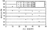
25% 이상 같은 20% 이상의 상대 습도를 갖는 퍼지 가스 혼합물은 포토레지스트의 성능에 관하여 특히 양호한 결과를 제공한다. 또한, 25% 이상이면서, 60% 같이 70% 미만인 상대 습도를 갖는 퍼지 가스 혼합물은 리소그래픽 투사 장치 내의 측정 시스템의 정확도에 관하여 양호한 예방적 영향(preventive effect)을 갖는다. 또한, 리소그래픽 장치 주변 공간, 예를 들어, 청정실 내부의 습도와 유사한 예를 들어, 약 40%의 습도는 최적의 결과를 제공하는 것으로 판명되었다.Purge gas mixtures having a relative humidity of at least 20%, such as at least 25%, provide particularly good results with respect to the performance of the photoresist. In addition, purge gas mixtures having a relative humidity of at least 25% and less than 70%, such as 60%, have a good preventive effect on the accuracy of the measurement system in the lithographic projection apparatus. In addition, a humidity of, for example, about 40%, similar to the humidity inside a lithographic apparatus, eg, inside a clean room, has been found to provide optimal results.
예로서, 더 높은 가스 유량, 개선된 증기 농도 제어 또는 단순화된 동작이 유리한 본 발명의 몇몇 실시예에서, 기화기는 하우징과, 퍼지 가스 흐름을 수납하는 제1 영역과, 기화가능 액체를 수납하는 제2 영역을 포함할 수 있으며, 제1 및 제2 영역은 액체 침투에 실질적으로내성적인 가스 투과성 중공 파이버 멤브레인에 의해 분리되어 있다. 이런 기화기는 퍼지 가스 혼합물을 형성하기 위해 퍼지 가스에액체 증기를 제공하기 위해 사용될 수 있다. 몇몇 실시예에서, 기화기는 하우징과, 퍼지 가스 흐름을 수납하는 제1 영역과, 물을 수납하는 제2 영역을 포함하는 가습기이고, 제1 및 제2 영역은 물 침투에 대해 실질적으로 내성적인 가스 투과성 멤브레인에 의해 분리되어 있다.For example, in some embodiments of the present invention where higher gas flow rates, improved vapor concentration control, or simplified operation are advantageous, the vaporizer includes a housing, a first region for receiving a purge gas stream, and a first container for receiving vaporizable liquid. It may comprise two regions, the first and second regions being separated by a gas permeable hollow fiber membrane that is substantially resistant to liquid penetration. Such vaporizers can be used to provide liquid vapor to the purge gas to form a purge gas mixture. In some embodiments, the vaporizer is a humidifier comprising a housing, a first region for receiving a purge gas flow, and a second region for receiving water, wherein the first and second regions are gases that are substantially resistant to water penetration. Separated by a permeable membrane.
기화기 멤브레인을 위한 적절한 재료는 폴리(테트라플루오로에틸렌-코-퍼플루오로-3,6-디옥사-4-메틸-7-옥텐 설포닉산)[poly(tetrafluoroethylene-co-perfluoro-3,6-dioxa-4-methyl-7-octene sulfonic acid)] 같은 열가소성 폴리머와, 폴리테트라 플루오로에틸렌 같은 과불화 폴리머(perfluorinated polymer)를 포함한다. 과불화 폴리머 같은 비-습윤성 폴리머는 특히 바람직하며, 특히, 고압 유체와 함께 사용하기에 적합하면서 무기 산화물(예를 들어, SOx 및 NOx, 여기서 x는 1 내지 3의 정수)이 실질적으로 없는 폴리머가 적합하다. 멤브레인은 절첩 또는 주름형성될 수 있는 시트일 수 있거나, 중공 파이버를 형성하도록 대향 측부들이 결합될 수 있다. 중공 파이버 멤브레인은 본 발명의 몇몇 형태에서 압출된 다공성 중공 파이버일 수 있다. 멤브레인은 하우징에 대해 멤브레인을 결합하기 위해 사용되는 임의의 밀봉제, 포팅 수지 또는 접착제와 조합하여 액체가 정상 동작 조건[예를 들어, 30 psig(0.207 Mpag) 이하의 압력]에서 퍼지 가스 내로 침투하는 것을 방지하며, 기체배기(outgassing)를 감소 또는 제거한다. 멤브레인은 퍼지 가스와 물 같은 기화가능 액체에 접촉하는 멤브레인의 표면적을 최대화하고, 멤브레인의 체적을 최소화하도록 구성되는 것이 바람직하다. 가습기는 후술된 바와 같이 하나 이상의 멤브레인을 수납할 수 있다.Suitable materials for the vaporizer membrane are poly (tetrafluoroethylene-co-perfluoro-3,6-dioxa-4-methyl-7-octene sulfonic acid) [poly (tetrafluoroethylene-co-perfluoro-3,6- dioxa-4-methyl-7-octene sulfonic acid)] and perfluorinated polymers such as polytetrafluoroethylene. Non-wetting polymers, such as perfluorinated polymers, are particularly preferred and are particularly suitable for use with high pressure fluids while being substantially free of inorganic oxides (eg, SO x and NO x , where x is an integer from 1 to 3). Polymers are suitable. The membrane can be a sheet that can be folded or crimped, or the opposing sides can be joined to form a hollow fiber. The hollow fiber membrane can be an extruded porous hollow fiber in some forms of the invention. The membrane, in combination with any sealant, potting resin or adhesive used to bond the membrane to the housing, allows liquid to penetrate into the purge gas at normal operating conditions (eg, pressures of 30 psig (0.207 Mpag) or less). Prevent or reduce outgassing. The membrane is preferably configured to maximize the surface area of the membrane in contact with the vaporizable liquid, such as purge gas and water, and to minimize the volume of the membrane. The humidifier may contain one or more membranes as described below.
튜브 및 셀 구조 내에 중공 파이버를 가지는 기화기가 사용될 수 있다. 몇몇 구현예에서, 기화기는 캐리어 가스에 수증기를 추가하기 위해 사용되며, 가습기 라 지칭될 수 있다. 예로서, 중공 파이버 멤브레인을 구비한 기화기 또는 가습기는 일반적으로 a) 제1 단부와 제2 단부를 구비하는 복수의 가스 투과성 중공 파이버 멤브레인의 다발로서 멤브레인은 외부면과 내부면을 가지며, 내부면은 제1 및 제2 영역 중 하나를 둘러싸는 복수의 가스 투과성 중공 파이버 멤브레인의 다발과, b) 파이버 단부가 유체 유동에 개방되어 있는 주변 하우징을 갖는 단부 구조체를 형성하는 액밀 밀봉부로 포팅된 다발의 각 단부와 c) 외부벽과 내부벽을 가지며, 내부벽은 내부벽과 중공 파이버 멤브레인 사이에 제1 및 제2 영역 중 나머지를 형성하는 하우징을 포함하고, d) 하우징은 퍼지 가스 소스와 퍼지 가스 혼합물 출구에 연결된 퍼지 가스 입구를 가지고, e) 하우징은 기화가능 액체 소스와 기화가능 액체 출구에 연결된 기화가능 액체 입구를 구비하며, 각 퍼지 가스 입구는 다발의 제1 단부에 연결되고, 퍼지 가스 혼합물 출구는 다발의 제2 단부에 연결되거나, 기화가능 액체 입구는 번들의 제1 단부에 연결되고 기화가능 액체 출구는 번드르이 제이 단부에 연결된다. 몇몇 실시예에서, 기화가능 액체는 물이다.Vaporizers with hollow fibers in the tube and cell structures can be used. In some embodiments, the vaporizer is used to add water vapor to the carrier gas and may be referred to as a humidifier. As an example, a vaporizer or humidifier with a hollow fiber membrane is generally a) a bundle of a plurality of gas permeable hollow fiber membranes having a first end and a second end, the membrane having an outer surface and an inner surface, the inner surface being A bundle of a plurality of gas permeable hollow fiber membranes surrounding one of the first and second regions, and b) a bundle of potted liquid seals forming an end structure having a peripheral housing with the fiber ends open to fluid flow. C) an outer wall and an inner wall, the inner wall including a housing defining the remainder of the first and second regions between the inner wall and the hollow fiber membrane, and d) the housing connected to the purge gas source and the purge gas mixture outlet. Having a purge gas inlet, e) the housing having a vaporizable liquid inlet connected to the vaporizable liquid source and the vaporizable liquid outlet; In comparison, each purge gas inlet is connected to the first end of the bundle, the purge gas mixture outlet is connected to the second end of the bundle, or the vaporizable liquid inlet is connected to the first end of the bundle and the vaporizable liquid outlet is loosely The second end is connected. In some embodiments, the vaporizable liquid is water.
기화기 또는 가습기로서 사용하기에 일반적으로 적합한 중공 파이버 멤브레인을 구비하는 장치는 통상적으로 멤브레인 접촉기라 지칭되며, 그 내용이 본 명세서에 참조로 통합되어 있는 미국 특허 제6,149,817호, 제6,235,641호, 제6,309,550호, 제6,402,818호, 제6,474,628호, 제6,616,841호, 제6,669,177호 및 제6,702,941호에 설명되어 있다. 비록, 다수의 멤브레인 접촉기가 선행 특허에서 액체(예로서, 물)에 가스를 추가하거나 그로부터 가스를 제거하기에 유용한 것으로 설명되어 있지만, 본 출원인은 멤브레인 접촉기는 일반적으로 기화기로서 동작할 수 있으며, 그래서, 액체로부터의 증기가 감소된 또는 약 1 ppt 미만의 오염물 추가로 퍼지 가스 흐름에 추가될 수 있다는 것을 발견하였다. 퍼지 가스 혼합물 발생기 내의 기화기는 퍼지 가스에 1 ppt 이상의 오염물을 부여하지 않고 높은 유량으로 퍼지 가스에 증기를 추가한다. 예로서, 기화기의 유출물은 1 ppt 미만의 비-메탄 탄화수소와 1 ppt 미만의 황 화합물을 포함한다. 적절한 멤브레인 기화기는 정화기에 의해 형성된 퍼지 가스의 완전성에 영향을 주지 않고 정화기의 하류에 사용될 수 있다. 가스 크로마토그래피/펄스형 플레임 이온화(Gas chromatography/pulse flame ionization), APIMS 또는 다른 추적 기술이 다공성 멤브레인 기화기의 청정성을 특징짓기 위해 사용될 수 있다. 가습기로서 사용하기에 적합하게 형성되고 오염물을 감소시키도록 구성 및/또는 처리될 수 있는 멤브레인 접촉기의 특정 예는 폴 코포레이션(Pall Corporation)에 의해 판매되는 인퓨저(등록상표)(Infuzor®)와, 멤브라나-샤를로트(Mebrana-Charlotte)에 의해 판매되는 리퀴-셀(등록상표)(Liqui-Cel®) 및 페르마푸어 엘엘씨(PermaPure LLC.)에 의해 판매되는 나피온(등록상표) 멤브레인 연료 전지 가습기(Nafion® Membrane fuel cell humidifier)를 포함한다.Devices having hollow fiber membranes generally suitable for use as vaporizers or humidifiers are commonly referred to as membrane contactors, and US Pat. Nos. 6,149,817, 6,235,641, 6,309,550, the contents of which are hereby incorporated by reference. 6,402,818, 6,474,628, 6,616,841, 6,669,177 and 6,702,941. Although a number of membrane contactors have been described in the prior patents as useful for adding or removing gas from a liquid (eg, water), the applicant can generally operate as a vaporizer, so It has been found that steam from the liquid can be added to the purge gas stream with reduced or additional less than about 1 ppt of contaminants. The vaporizer in the purge gas mixture generator adds steam to the purge gas at a high flow rate without imparting more than 1 ppt of contaminants to the purge gas. By way of example, the effluent of the vaporizer includes less than 1 ppt of non-methane hydrocarbons and less than 1 ppt of sulfur compounds. Suitable membrane vaporizers can be used downstream of the purifier without affecting the integrity of the purge gas formed by the purifier. Gas chromatography / pulse flame ionization, APIMS or other tracking techniques can be used to characterize the cleanliness of porous membrane vaporizers. Specific examples of membrane contactors that are suitable for use as a humidifier and that can be configured and / or treated to reduce contaminants include Infuzor® sold by Pall Corporation, and Membrane. Liqui-Cel® sold by Lana-Charlotte and Nafion® membrane fuel cell humidifier sold by PermaPure LLC. Nafion® Membrane fuel cell humidifier).
특히 양호한 기화기 또는 가습기의 개략도가 도5에 도시되어 있으며, 그 상업적 실시예는 메사츄세츠주 빌레리카 소재의 마이크롤리스사(Mykrolis® Corporation)[현재 엔테그리스, 인크.(Entegris, Inc.)]에 의해 판매되는 피하서(등록상표) II 멤브레인 접촉기(pHasor® II Membrane Contactor)이다. 도5에 예시된 바와 같이, 유체(1)는 파이버 루멘(3)을 통해 가습기(2)에 진입하고, 멤브레인에 의해 유체(4)로부터 분리되어 있는 상태인 루멘(3) 내에 있는 동안 가습기(2) 의 내부를 횡단하며, 연결부(40)에서 파이버 루멘을 통해 접촉기(2)를 벗어난다. 유체(4)는 연결부(30)를 통해 하우징에 진입하고, 파이버의 외경과 하우징의 내벽 사이의 공간을 실질적으로 충전하며, 커넥터(20)를 통해 나간다.A schematic of a particularly preferred vaporizer or humidifier is shown in FIG. 5, a commercial example of which is provided by Mykrolis® Corporation (now Entegris, Inc.), Billerica, Massachusetts. PHasor® II Membrane Contactor sold. As illustrated in FIG. 5, the fluid 1 enters the
본 발명의 기화기 또는 가습기의 이러한 형태에 사용되는 가스 투과성 중공 파이버 멤브레인은 통상적으로 a) 다공성 표피의 내부면과, 다공성 외부면과, 그 사이의 다공성 지지구조체를 구비하는 중공 파이버 멤브레인, b) 비-다공성 표피의 내부면과, 다공성 외부면과, 그 사이의 다공성 지지 구조체를 구비하는 중공 파이버 멤브레인, c) 다공성 표피의 외부면과, 다공성 내부면과, 그 사이의 다공성 지지 구조체를 귀하는 중공 파이버 멤브레인 또는 d) 비-다공성 표피의 외부면과, 다공성 내부면과, 그 사이의 다공성 지지 구조체를 구비하는 중공 파이버 멤브레인 중하나이다. 이들 중공 파이버 멤브레인은 약 350 ㎛ 내지 약 1450 ㎛의 외경을 가질 수 있다.Gas permeable hollow fiber membranes used in this type of vaporizer or humidifier of the present invention are typically a) hollow fiber membranes having an inner surface of the porous skin, a porous outer surface, and a porous support structure therebetween, b) non A hollow fiber membrane having an inner surface of the porous skin, a porous outer surface, and a porous support structure there between, c) an outer surface of the porous skin, a porous inner surface, and a porous support structure therebetween. Fiber membrane or d) a hollow fiber membrane having an outer surface of the non-porous skin, a porous inner surface and a porous support structure therebetween. These hollow fiber membranes can have an outer diameter of about 350 μm to about 1450 μm.
이들 중공 파이버 멤브레인이 다공성 표피의 내부면과, 다공성 외부면과, 그 사이의 다공성 지지 구조체를 갖는 중공 파이버 멤브레인이거나, 다공성 표피의 외부면과, 다공성 내부면과, 그 사이의 다공성 지지 구조체를 갖는 중공 파이버 멤브레인일 때, 가공성 표피의 표면 공극은 바람직하게는 직경 또는 그 최대 형상비가 약 0.001 ㎛ 내지 약 0.005 ㎛이다. 표피형 표면 내의 공극은 액체 유동에 대면하는 것이 바람직하다.These hollow fiber membranes are hollow fiber membranes having an inner surface of the porous skin, a porous outer surface, and a porous support structure therebetween, or having a outer surface of the porous skin, a porous inner surface, and a porous support structure therebetween. In the case of hollow fiber membranes, the surface voids of the workable skin preferably have a diameter or a maximum aspect ratio of about 0.001 μm to about 0.005 μm. The voids in the epidermal surface preferably face liquid flow.
이들 중공 멤브레인을 위한 적절한 재료는 폴리(테트라플루오로에틸렌-코-퍼플로오로(알킬비닐에테르))(폴리(PTFE-CO-PFVAE))[poly(tetrafluoroethylene-co- perfluoro(alkylvinylether))(poly(PTFE-CO-PFVAE))], 폴리(테트라플루오로에틸렌-코-헥사플로오로프로필렌)(FEP)[poly(tetrafluoroethylene-co-hexafluoropropylene)(FEP)] 또는 그 혼합물 같은 과불화 열가소성 폴리머를 포함하며, 그 이유는 이들 폴리머가 용례의 가혹한 조건에 의해 부정적 영향을 받지 않기 때문이다. PFA 테플론(등록상표)(PFA Teflon®)은 알킬이 주로 또는 완전히 프로필 그룹인 폴리(PTFE-CO-PFVAE)의 일 예이다. FEP 테플론(등록상표)(FEP Teflon®)은 폴리(FEP)의 일 예이다. 양자 모두는 듀폰(DuPont)에 의해 제조된다. 네오플론(등록상표)(Neoflon®) PFA[다이킨 인더스트리스(Daikin Industries)]는 듀폰의 PFA 테플론(등록상표)과 유사한 폴리머이다. 알킬 그룹이 주로 메틸인 폴리(PTFE-CO-PFVAE)는 그 내용이 본 명세서에 참조로 통합되어 있는 미국 특허 제5,463,006호에 개시되어 있다. 양호한 폴리머는 하이플론(등록상표)(Hyflon®) 폴리 (PTFE-CO-PFVAE) 620이며, 이는 뉴저지주 토로페어 소재의 오시몬트 USA 인크(Ausimount USA, Inc.)로부터 입수할 수 있다. 이들 폴리머를 중공 파이버 멤브레인으로 형성하는 방법은 그 내용이 본 명세서에 참조로 통합되어 있는 미국 특허 제6,582,496호 및 제4,902,456호에 개시되어 있다.Suitable materials for these hollow membranes are poly (tetrafluoroethylene-co-perfluoro (alkylvinylether)) (poly (PTFE-CO-PFVAE)) [poly (tetrafluoroethylene-co-perfluoro (alkylvinylether)) (poly (PTFE-CO-PFVAE))], poly (tetrafluoroethylene-co-hexafluoropropylene) (FEP) [poly (tetrafluoroethylene-co-hexafluoropropylene) (FEP)] or mixtures thereof, and the like. The reason is that these polymers are not negatively affected by the harsh conditions of the application. PFA Teflon® (PFA Teflon®) is an example of poly (PTFE-CO-PFVAE) in which alkyl is predominantly or completely propyl group. FEP Teflon® (FEP Teflon®) is an example of poly (FEP). Both are manufactured by DuPont. Neolon® PFA (Daikin Industries) is a polymer similar to DuPont's PFA Teflon®. Poly (PTFE-CO-PFVAE) in which the alkyl group is predominantly methyl is disclosed in US Pat. No. 5,463,006, the contents of which are incorporated herein by reference. Preferred polymers are Hyflon® Poly (PTFE-CO-PFVAE) 620, which is available from Ausimount USA, Inc., Toropair, NJ. Methods of forming these polymers into hollow fiber membranes are disclosed in US Pat. Nos. 6,582,496 and 4,902,456, the contents of which are incorporated herein by reference.
포팅은 각 파이버 둘레에 액밀 밀봉부를 구비하는 튜브 시트를 형성하는 프로세스이다. 튜브 시트 또는 포트는 환경으로부터 가습기의 내부를 분리시킨다. 포트는 단일체형 단부 구조체를 형성하도록 하우징 용기에 열적으로 접합된다. 단일체형 단부 구조체는 파이버 및 포트가 과불화 열가소성 재료만으로 구성된 단일 엔티티를 형성하도록 하우징에 접합될 때 얻어진다. 단일체형 단부 구조체는 포트 단부 내에 둘러싸여진 파이버 번들의 부분과, 포트 및 그 내부면이 포트와 합동이며, 이에 접합되어 있는 과불화 열가소성 하우징의 단부 부분을 포함한다. 단일 구조체를 형성함으로써, 더 강인한 기화기 또는 가습기가 생성되며, 하우징 및 포트의 계면에서 누설이나 기타 고장이 덜 발생한다. 또한, 단일체형 단부 구조체는 제 위치에 파이버를 접합하기 위한 에폭시 같은 접착제의 사용에 대한 필요성을 피할 수 있게 한다. 이런 접착제는 통상적으로 휘발성 탄화수소를 포함하며, 이는 기화기 또는 가습기를 통해 유동하는 퍼지 가스를 오염시킨다. 예로서, 페르마 푸어(Perma Pure)에 의해 판매되는 리퀴-셀 가습기를 사용하여 가습된 퍼지 가스는 인지할 수 있는 에폭시 냄새가 나며, 이는 명백히 수백 ppm일 수 있는 퍼지 가스 내의 허용불가한 탄화수소 함량을 나타낸다. 포팅 및 접합 프로세스는 그 교지가 본 명세서에 참조로 통합되어 있는 1999년 1월 29일자로 출원된 미국 출원 제60/117,853호에 설명된 방법의 적용이며, 미국 특허 제6,582,496호에 개시되어 있다. 중공 파이버 멤브레인의 다발은 다발의 제1 및 제2 단부가 액밀 과불화 열가소성 밀봉부로 포팅되어 단부들의 파이버가 유체 유동에 개별적으로 개방되어 있는 주변 과불화 열가소성 하우징을 구비하는 제1 및 제2 단부 양자 모두를 포함하는 단일 단일체형 단부 구조체를 형성하도록 준비되는 것이 바람직하다.Potting is the process of forming a tube sheet with a liquid tight seal around each fiber. The tube sheet or port separates the interior of the humidifier from the environment. The port is thermally bonded to the housing container to form a monolithic end structure. Monolithic end structures are obtained when the fibers and ports are joined to the housing to form a single entity consisting solely of perfluorinated thermoplastic material. The monolithic end structure includes a portion of a fiber bundle enclosed within a port end and an end portion of the perfluorinated thermoplastic housing that is coherent with and bonded to the port. By forming a unitary structure, more robust vaporizers or humidifiers are created, with less leakage or other failures at the interface of the housing and port. In addition, the monolithic end structure allows to avoid the need for the use of an adhesive such as epoxy to bond the fibers in place. Such adhesives typically comprise volatile hydrocarbons, which contaminate the purge gas flowing through the vaporizer or humidifier. By way of example, a purge gas humidified using a Liqui-Cell humidifier sold by Perma Pure has a perceptible odor of epoxy, which indicates an unacceptable hydrocarbon content in the purge gas, which can be apparently hundreds of ppm. Indicates. The potting and bonding process is the application of the method described in
본 발명의 일 형태는 퍼지 가스에 증기를 추가하는 장치이다. 이 장치는 하나 이상의 재생가능한 정화기와 유체 연통하는 소스 가스 입구와, 기화기의 퍼지 가스 입구와 유체 연통하는 정화기로부터의 퍼지 가스 출구를 포함할 수 있다. 정화기는 독립적으로 재생가능할 수 있으며, 퍼지 가스를 형성하기 위해 소스 가스 입구로부터 정화기로 오염물을 제거한다. 기화기는 하우징 및 하나 이상의 미소다공 중공 파이버 멤브레인을 포함할 수 있다. 하우징은 미소다공 중공 파이버의 제1 측부와 유체 연통하는 퍼지 가스 혼합물 출구 및 퍼지 가스 입구를 구비한다. 하우징은 미소다공 중공 파이버의 제2 측부와 유체 연통하는 기화가능 액체를 위한 출구 및 기화가능 액체를 위한 입구를 갖는다. 미소다공 중공 파이버 멤브레인은 리소그래픽 투사 시스템 내의 광학 구성요소의 광학 특성을 열화시키는 오염물을 기화기의 기화가능 액체로부터의 증기에 1 ppb 미만으로 부여하고, 몇몇 실시예에서는 이런 휘발성 오염물을 100 ppt 미만으로 부여한다. 기화기는 이런 오염물을 제거 또는 감소시키도록 처리되거나 세정될 수 있다. 미소다공 중공 파이버는 기화가능 액체에 의한 액체 침투에 대해 내성적이다. One embodiment of the present invention is an apparatus for adding steam to a purge gas. The apparatus may include a source gas inlet in fluid communication with one or more renewable purifiers and a purge gas outlet from the purifier in fluid communication with the purge gas inlet of the vaporizer. The purifier can be independently renewable and removes contaminants from the source gas inlet to form purge gas. The vaporizer may include a housing and one or more microporous hollow fiber membranes. The housing has a purge gas mixture outlet and a purge gas inlet in fluid communication with the first side of the microporous hollow fiber. The housing has an outlet for the vaporizable liquid and an inlet for the vaporizable liquid in fluid communication with the second side of the microporous hollow fiber. Microporous hollow fiber membranes impart contaminants that degrade optical properties of optical components in lithographic projection systems to less than 1 ppb to vapors from vaporizable liquids in vaporizers, and in some embodiments, to less than 100 ppt of such volatile contaminants. Grant. The vaporizer can be treated or cleaned to remove or reduce such contaminants. Microporous hollow fibers are resistant to liquid penetration by vaporizable liquids.
장치는 기화기, 퍼지 가스 입구, 퍼지 가스 혼합물 출구 또는 이들의 조합의 온도를 하나 이상의 설정점 범위 이내로 유지하는 온도 규제 시스템을 더 포함할 수 있다. 온도 규제 시스템은 하나 이상의 온도 측정 장치와, 장치의 하나 이상의 영역 또는 구역의 온도를 변경할 수 있는 하나 이상의 열 교환기 및 제어기를 포함할 수 있다. 제어기는 온도 측정 장치로부터 온도 입력을 수신하고 하나 이상의 열 교환기의 동작을 제어함으로써 장치의 온도를 변화시킨다. 열 교환기는 가열기, 냉각기, 펠티어 냉각기, 팬 또는 다른 장치를 포함할 수 있지만, 이들에 한정되지는 않는다. 온도 규제 시스템은 증발기, 퍼지 가스, 퍼지 가스 혼합물 또는 이들의 임의의 조합의 온도를 설정점에 대해 약 ±5℃ 이하, 몇몇 구현예에서는 ±1℃ 이하, 또 다른 구현예에서는 ±0.5℃ 이하의 온도 범위 이내로 유지할 수 있 다. 온도 규제 시스템은 증기 응결이 감소 또는 제거되도록 퍼지 가스 혼합물을 증기의 응결 온도를 초과한 온도로 유지할 수 있다. 몇몇 구현예에서, 온도 규제 시스템은 약 ±1℃ 이하의 온도 범위 이내로, 증기의 응결 온도 보다 높은 퍼지 가스 혼합물 내의 증기의 온도를 유지할 수 있다. 온도 규제 시스템은 퍼지 가스 혼합물인 퍼지 가스 내의 증기의 농도가 5% 미만만큼, 몇몇 구현예에서는 1% 미만만큼, 또 다른 형태에서는 0.5% 미만만큼 변하는 농도를 갖도록 장치의 온도를 유지할 수 있다. 온도 규제 시스템은 장치 내의 온도 구배를 유지할 수 있다. 장치의 온도를 유지함으로써, 온도 규제 시스템은 실질적으로 일정한 증기 농도를 제공한다. 몇몇 형태에서, 온도 규제 시스템은 서로 다른 퍼지 가스 유량에서 실질적으로 일정한 온도로 퍼지 가스 혼합물의 온도를 유지한다. The apparatus may further include a temperature regulation system that maintains the temperature of the vaporizer, purge gas inlet, purge gas mixture outlet, or a combination thereof within one or more set point ranges. The temperature regulation system may include one or more temperature measuring devices and one or more heat exchangers and controllers capable of changing the temperature of one or more regions or zones of the device. The controller changes the temperature of the device by receiving a temperature input from the temperature measuring device and controlling the operation of one or more heat exchangers. Heat exchangers may include, but are not limited to, heaters, coolers, Peltier coolers, fans or other devices. The temperature regulating system may set the temperature of the evaporator, purge gas, purge gas mixture, or any combination thereof up to about ± 5 ° C. relative to the set point, up to ± 1 ° C. in some embodiments, up to ± 0.5 ° C. in another embodiment. It can be kept within the temperature range. The temperature regulation system may maintain the purge gas mixture at a temperature above the condensation temperature of the vapor so that vapor condensation is reduced or eliminated. In some embodiments, the temperature regulation system can maintain the temperature of the steam in the purge gas mixture above the condensation temperature of the steam within a temperature range of about ± 1 ° C. or less. The temperature regulation system may maintain the temperature of the device such that the concentration of vapor in the purge gas mixture purge gas varies by less than 5%, in some embodiments by less than 1%, and in other forms by less than 0.5%. The temperature regulation system can maintain a temperature gradient within the device. By maintaining the temperature of the device, the temperature regulation system provides a substantially constant vapor concentration. In some forms, the temperature regulation system maintains the temperature of the purge gas mixture at a substantially constant temperature at different purge gas flow rates.
장치는 미소다공 중공 파이버 내의 기화가능 액체 내의 퍼지 가스 버블이 형성을 방지하고 5% 미만만큼, 몇몇 구현예에서는 1% 미만만큼, 또 다른 형태에서는 0.5% 미만만큼 변하는 퍼지 가스 혼합물 내의 증기 농도를 제공하도록 기화가능 액체의 압력, 퍼지 가스의 압력 또는 이들의 임의의 조합을 유지하는 압력 규제 시스템을 포함할 수 있다. 압력 규제 시스템은 그 공급 압력이 예로서, 가압 가스 또는 펌프에 의해 변경될 수 있는 가압된 기화가능 유체의 소스를 포함할 수 있다. 압력 규제 시스템은 기화기 내의 중공 파이버 다공성 멤브레인의 일 측부 상의 기화가능 액체의 압력을 측정 및 변경하도록 압력 트랜스듀서, 계량 밸브 및 제어기를 포함할 수 있다. 압력 규제 시스템은 기화기 내의 다공성 중공 파이버의 제2 측부와 접촉하는 퍼지 가스 또는 퍼지 가스 혼합물의 압력을 측정 및 변경하기 위 해 하나 이상의 압력 트랜스듀서, 계량 밸브 및 제어기를 포함할 수 있다. 압력 규제 시스템은 퍼지 가스 또는 퍼지 가스 혼합물의 압력을 유지하고, 기화가능 액체 내의 퍼기 가스 기포의 형성을 방지할 수 있다. 장치의 몇몇 형태에서, 압력 규제 시스템은 퍼지 가스의 압력을 약 5 psi(0.034 Mpa) 이상 초과한 기화가능 액체 압력을 유지한다. 압력 규제 시스템은 압력 제어기 및 배압 조절기(back pressure regulator)를 포함할 수 있다.The apparatus prevents the formation of purge gas bubbles in the vaporizable liquid in the microporous hollow fiber and provides a vapor concentration in the purge gas mixture that varies by less than 5%, in some embodiments by less than 1%, and in other forms by less than 0.5%. And a pressure regulation system to maintain the pressure of the vaporizable liquid, the pressure of the purge gas, or any combination thereof. The pressure regulating system may comprise a source of pressurized vaporizable fluid whose supply pressure may be changed by, for example, pressurized gas or a pump. The pressure regulation system can include a pressure transducer, a metering valve and a controller to measure and change the pressure of the vaporizable liquid on one side of the hollow fiber porous membrane in the vaporizer. The pressure regulation system may include one or more pressure transducers, metering valves, and controllers to measure and change the pressure of the purge gas or the purge gas mixture in contact with the second side of the porous hollow fiber in the vaporizer. The pressure regulating system can maintain the pressure of the purge gas or the purge gas mixture and prevent the formation of purge gas bubbles in the vaporizable liquid. In some forms of apparatus, the pressure regulating system maintains a vaporizable liquid pressure that exceeds the pressure of the purge gas by at least about 5 psi (0.034 Mpa). The pressure regulation system may include a pressure controller and a back pressure regulator.
본 발명의 구현예의 장치는 퍼지 가스의 유량, 희석 가스, 장치로부터의 퍼지 가스 혼합물의 유량 또는 이들의 임의의 조합을 유지하는 유동 제어 시스템을 포함할 수 있다. 유동 제어 시스템은 하나 이상의 질량 유동 제어기, 하나 이상의 증기 농도 센서 및 제어기를 포함할 수 있다. 증기 농도 또는 증기 포화 설정점의 분율(fraction)에 기초하여, 제어기는 증기 센서로부터 농도 출력을 취하고, 증기의 원하는 또는 설정점 농도를 갖는 희석된 퍼지 가스 혼합물을 생성하도록 퍼지 가스 혼합물과 퍼지 가스의 혼합물을 변경한다. 유동 제어 시스템은 5% 미만, 몇몇 구현예에서는 1% 미만, 또 다른 형태에서는 0.5% 미만만큼 변하는 퍼지 가스 혼합물 내의 증기 농도를 제공할 수 있다.The apparatus of an embodiment of the present invention may include a flow control system that maintains the flow rate of the purge gas, the diluent gas, the flow rate of the purge gas mixture from the apparatus, or any combination thereof. The flow control system can include one or more mass flow controllers, one or more vapor concentration sensors, and a controller. Based on the vapor concentration or fraction of the steam saturation set point, the controller takes the concentration output from the steam sensor and produces a diluted purge gas mixture having a desired or set point concentration of steam. Change the mixture. The flow control system may provide a vapor concentration in the purge gas mixture that varies by less than 5%, in some embodiments less than 1%, and in other forms less than 0.5%.
장치는 1 ppb 미만, 몇몇 구현예에서는 1 ppt 미만의 휘발성 불순물을 갖는 퍼지 가스 혼합물 또는 희석된 퍼지 가스 혼합물을 형성할 수 있다. 본 발명의 몇몇 형태에서, 퍼지 가스 혼합물은 기화기로부터의 퍼지 가스 혼합물 내의 액체 증기의 양이 리소그래픽 투사 시스템 또는 다른 전달점의 온도 및 압력에서 퍼지 가스를 포화시키는 증기의 양의 약 20% 보다 큰 상태로, 약 20 slm 보다 큰 퍼지 가 스 유량으로 형성될 수 있다. 퍼지 가스 혼합물 내의 증기의 조성 및 농도는 장치 내의 온도, 압력, 흐름 또는 이들의 임의의 조합을 제어함으로써 변경될 수 있다. 퍼지 가스 혼합물 내의 증기의 농도는 기화기의 퍼지 가스 혼합물 출구로부터의 퍼지 가스 혼합물과 함께 퍼지 가스를 혼합하는 단계 또는 작업에 의해 부가적인 퍼지 가스와의 희석에 의해 추가로 변경될 수 있다. 퍼지 가스 혼합물 또는 희석된 퍼지 가스 혼합물은 액체 트랩을 통해 퍼지 가스 혼합물을 포함하는 증기를 통과시키고, 액체를 제거하는 작업에 의해 추가 처리될 수 있다.The apparatus may form a purge gas mixture or a diluted purge gas mixture having volatile impurities of less than 1 ppb, and in some embodiments less than 1 ppt. In some forms of the present invention, the purge gas mixture is characterized in that the amount of liquid vapor in the purge gas mixture from the vaporizer is greater than about 20% of the amount of vapor that saturates the purge gas at the temperature and pressure of the lithographic projection system or other delivery point. In this state, purge gas flow rates greater than about 20 slm may be formed. The composition and concentration of the vapor in the purge gas mixture can be altered by controlling the temperature, pressure, flow or any combination thereof in the apparatus. The concentration of the vapor in the purge gas mixture may be further modified by dilution with additional purge gas by mixing or purging the purge gas with the purge gas mixture from the purge gas mixture outlet of the vaporizer. The purge gas mixture or diluted purge gas mixture may be further processed by passing the vapor containing the purge gas mixture through the liquid trap and removing the liquid.
기화가능 유체는 계량 밸브를 사용하여 가압된 소스로부터 중공 파이버로 공급될 수 있다. 선택적으로, 기화가능 유체는 재순환 루프 또는 데드 엔드 공급부(dead end feed) 내에서 흐르는 기화가능 액체와 함께 증발기 내로 공급될 수 있다. 예로서, 기화가능 액체는 온도 제어된 용기 내에 존재하고, 펌프에 의해 기화기 내로 공급되며, 임의의 잔여 기화가능 액체는 추가 가열을 위해 용기로 복귀될 수 있다. 몇몇 구현예에서, 접촉기의 액체 측부의 출구는 폐쇄되고, 기화가능 유체는 퍼지 가스에 의해 기화될 때 가압된 소스로부터 기화기에 공급된다.The vaporizable fluid may be supplied to the hollow fiber from the pressurized source using a metering valve. Optionally, the vaporizable fluid may be fed into the evaporator with vaporizable liquid flowing in a recycle loop or dead end feed. By way of example, the vaporizable liquid is present in a temperature controlled vessel, supplied by the pump into the vaporizer, and any residual vaporizable liquid can be returned to the vessel for further heating. In some embodiments, the outlet of the liquid side of the contactor is closed and the vaporizable fluid is supplied to the vaporizer from the pressurized source when vaporized by the purge gas.
도11(A)는 질량 유동 제어기(1112, 1116)에 의해 제어될 수 있는 퍼지 가스(1110)의 유동을 발생시키기 위해 소스(미도시, 그러나, 가정용 질소 공급원, 실린더로부터의 전자 등급 가스 등일 수 있음)로부터, 규제기(1104)를 통해 정화기(1108)로 가스(1102)를 추가 상태조절하는 퍼지 가스 혼합물 공급 시스템을 개략적으로 예시한다. 정화기(1108)는 하나 이상의 독립적 및 개별적 재생가능한 정화기를 포함할 수 있다. 선택적 압력 트랜스듀서(1114), 온도 트랜스듀서(1106) 및 증기 센서(미도시)도 존재할 수 있다. 그 증기가 포토레지스트, 기타 리소그래픽 화학 코팅 또는 다른 기판 코팅의 활성도를 제어, 향상 또는 변경하기 위해 사용될 수 있는 비오염 기화가능 액체(1130)는 소스(미도시)로부터 기화기 또는 접촉기(1120)로 공급될 수 있다. 예로서, 소스(미도시)로부터의 물 같은 기화가능 액체(1130)는 압력 규제기(1128)를 통해, 기화기 또는 가습기(1120)를 통해, 그리고, 선택적 유량 제어 밸브(1124)를 통해 흐를 수 있다. 퍼지 가스 내의 증기는 증기 없는 퍼지 가스에 비해 포토 레지스트의 활성도를 향상시며, 퍼지 가스 내의 증기 농도를 유지함으로써, 퍼지 가스 혼합물이 포토레지스트 활성도를 제어하기 위해 사용될 수 있다. 선택적 압력 트랜스듀서(1126) 및 온도 트랜스듀서(1122)도 도시되어 있다. 물(1130)은 가습기(1120)를 통해 질량 유동 제어기(1112)로부터 이동하는 것으로 예시되어 있는 퍼지 가스 프름(1110)의 방향에 반대 흐름 방향으로 유동할 수 있다. 몇몇 형태에서, 물 및 가스는 동일한 방향으로 흐를 수 있다. 질량 유동 제어기(1112)로부터의 퍼지 가스(1110)는 퍼지 가스 혼합물(1140)을 형성하도록 가습기(1120) 내의 액체 침투를 저지하는 다공성 멤브레인을 통해 액체 증기를 픽업한다. 퍼지 가스는 출구(1136)에 연결된 리소그래픽 투사 시스템에 공급되어 사용될 수 있다. 퍼지 가스 혼합물(1140)은 선택적으로, 출구(1136)에 연결된 리소그래픽 투사 시스템에 공급 및 사용될 수 있는 희석된 퍼지 가스 혼합물(1144)을 형성하도록 제2 질량 유동 제어기(1116)로부터의 퍼지 가스와 혼합되어 희석될 수 있다. 이 희석은 기화기(1120)를 통한 질량 유동 제어기(1112)로부터의 퍼지 가스의 일정한 흐름을 유지하기 위해 사용될 수 있고, 기화기(1120)의 온도 제어를 도울 수 있다. 장치 내의 그 위치가 변할 수 있는 선택적 트랩(1132)은 가습기(1120)로부터 임의의 액적 또는 응결물을 제거하기 위해 사용될 수 있다. 트랩은 입자 필터 또는 액체 트랩일 수 있으며, 그 위치는 액체 또는 입자 액적의 감소를 제공하도록 선택된다. 증기 센서(1138)는 선택적으로, 기화기(1120)의 하류에 배치될 수 있다. 선택적으로, 제어기는 증기 센서(1138)의 출력을 수신하고, 희석된 퍼지 가스 혼합물(1144) 내의 증기의 농도를 변경 또는 유지하도록 질량 유동 제어기(1116)를 통한 퍼지 가스 흐름(1110)을 변경하기 위해 사용될 수 있다. 몇몇 형태에서, 증기 센서는 습기 센서이다. 퍼지 가스 혼합물(1144)은 리소그래픽 투사 시스템 또는 퍼지 가스 혼합물을 사용한 퍼징을 활용하는 다른 시스템에 사용하기 위해 출구(1136)에 제공될 수 있다.11 (A) may be a source (not shown, but a domestic nitrogen source, electron grade gas from a cylinder, etc.) to generate a flow of
도11B는 질량 유동 제어기(1162, 1166)로 흐르는 퍼지 가스 흐름(1160)을 발생시키도록 소스(도시되어 있지 않지만, 가정용 질소 공급원, 전자 등급 가스 실린더, 가스 발생기 등일 수 있음)로부터 규제기(1150)를 통한 정화기(1158)로의 가스(1152)를 추가로 상태조정하는 퍼지 가스 혼합물 공급 시스템을 예시한다. 정화기(1158)는 하나 이상의 독립적이고 개별적인 재생가능 정화기를 포함할 수 있다. 하나 이상의 선택적 압력 트랜스듀서(1164), 온도 트랜스듀서(1156), 증기 센서(미도시)가 기화기(1170) 이전에 배치될 수 있다. 소스(미도시)로부터의 비오염 기화가능 액체(1180), 예로서, 물은 압력 규제기(1178)를 통해, 접촉기 또는 가습기(1170)를 통해, 그리고, 선택적 유동 제어 밸브(1174)를 통해 흐를 수 있다. 선택적 압력 트랜스듀서(1176) 및 온도 트랜스듀서(1172)도 도시되어 있다. 도시된 바와 같이, 기화가능 액체는 질량 유동 제어기(1162)로부터 접촉기(1170)를 통해 퍼지 가스 흐름(1160)의 방향에 반대 흐름 방향으로 흐를 수 있다. 질량 유동 제어기(1162)로부터의 퍼지 가스는 퍼지 가스 혼합물(1190)을 형성하도록 다공성 멤브레인을 통해 액체 증기를 취한다. 퍼지 가스 혼합물(1190)은 선택적으로 희석된 퍼지 가스 혼합물(1194)을 형성하도록 제2 질량 유동 제어기(1166)로부터의 퍼지 가스(1160)와 혼합 및 희석될 수 있다. 이 희석은 기화기(1170)를 통한 퍼지 가스의 일정한 흐름을 유지하기 위해 사용될 수 있고, 기화기의 온도 제어를 보조할 수 있다. 도11B는 퍼지 가스 혼합물(1190) 내의 증기의 응결을 피하는 온도 범위로 발생된 퍼지 가스 혼합물(1194)의 온도를 유지하기 위해 사용될 수 있는 열 교환기 또는 온도 제어된 환경(1192)을 예시한다. 이 온도는 퍼지 가스 혼합물 내의 증기의 응결점을 초과한다. 예로서, 물의 분압이 포화 압력에 근접하는 경우, 수증기가 그 액체 상태로 변화하기 위한 온도에는 단지 미소한 강하만이 존재할 수 있다. 온도 제어 환경(1192)은 접촉기 내의 액체의 온도를 유지하고, 그에 의해, 기화기(1170)로부터의 증기의 농도를 기판 상의 포토 레지스트 또는 기타 패턴화된 코팅의 적절한 반응성을 제공하기 위해 사용될 수 있는 범위로 유지하기 위해 사용될 수 있다. 예로서, 수증기를 갖는 온조 조정된 퍼지 가스 혼합물은 도2의 리소그래픽 투사 장치의 조명 광학장치 및/또는 투사 렌즈(PL)에 사용하기 위해 퍼지 가스 혼합물 출구(1186)에 제공될 수 있다. 퍼지 가스 혼합물은 질량 유동 제어기(1166)로부터의 퍼지 가스(1160)에 의한 희석과 함께 또는 이러한 희석 없이 출구(1186)에 제공될 수 있다. 증기 센서(1184)는 선택적으로 증발기(1170)의 하류 에 배치될 수 있다. 선택적으로, 제어기는 증기 센서(1184)의 출력을 수신하고, 희석된 퍼지 가스 혼합물(1194) 내의 증기의 농도를 변경 또는 유지하기 위해 질량 유동 제어기(1166)를 통해 퍼지 가스 흐름(1160)을 변경하기 위해 사용될 수 있다. 몇몇 형태에서, 증기 센서는 습기 센서이다. 퍼지 가스 혼합물(1194)은 리소그래픽 투사 시스템 또는 퍼지 가스 혼합물을 이용한 퍼징을 사용하는 다른 시그템에 사용하기 위해 출구(1186)에 제공될 수 있다.11B shows
도14는 질량 유동 제어기(1416, 1440) 내로 흐르는 퍼지 가스(1412)를 발생시키도록 소스(미도시)로부터 규제기(1404)를 통한 정화기(1408) 내로의 가스(1402)를 추가 상태조정하는 퍼지 가스 혼합물 공급 시스템을 개략적으로 예시한다. 정화기(1408)는 하나 이상의 독립적 및 개별적 재생가능 정화기를 포함할 수 있다. 선택적 압력 트랜스듀서(1420), 온도 트랜스듀서(1424) 및 증기 센서(미도시)도 존재할 수 있다. 포토 레지스트 또는 기타 리소그래픽 화삭제 코팅의 활성도를 제어하기 위해 사용될 수 있는 기화가능 액체 조성물(1464)은 소스(미도시)로부터 하나 이상의 기화기(1428, 1432)로 공급될 수 있다. 도14에 도시된 바와 같이, 하나 이상의 기화기(1428, 1444)는 병렬 관계로 구성될 수 있다. 대안적으로, 접촉기는 직렬 구조로 연결될 수 있다. 예로서, 소스로부터의 물 같은 기화가능 액체(1464)는 압력 규제기(1460)를 통해, 도관(1432)에 의해 상호연결된 기화기 또는 가습기(1428, 1444)를 통해, 그리고, 선택적 유동 제어 밸브(1436)를 통해 흐를 수 있다. 선택적 압력 트랜스듀서(1456) 및 온도 트랜스듀서(1452)도 사용될 수 있다. 기화기(1428, 1444)를 통한 액체(1464)는 질량 유동 제어기(1416)로부터의 퍼지 가스(1412)의 방향에 대한 반대 흐름 방향으로 흐를 수 있다. 질량 유동 제어기(1416)로부터의 퍼지 가스(1412)는 퍼지 가스 혼합물(1468)을 형성하도록 증발기(1428, 1444) 내의 다공성 멤브레인을 통해 기화가능 액체로부터 증기를 픽업한다. 다공성 멤브레인은 액체 침투를 저지한다. 퍼지 가스는 출구(1488)에 연결된 리소그래픽 투사 시스템에 공급 및 사용될 수 있다. 퍼지 가스 혼합물(1468)은 선택적으로, 출구(1488)에 연결된 리소그래픽 투사 시스템에 압력 규제기(1484)를 통해 공급되어 사용될 수 있는 희석된 퍼지 가스(1480)를 형성하도록 제2 질량 유동 제어기(1440)로부터의 퍼지 가스(1480)와 혼합 및 희석될 수 있다. 희석은 증발기의 온도 제어를 도울 수 있는 하나 이상의 증발기(1428)를 통한 질량 유동 제어기(1412)로부터의 퍼지 가스의 일정한 흐름을 유지하도록 사용될 수 있다. 그 위치가 매니폴드 내에서 변경될 수 있는 선택적 트랩(1448)이 기화기로부터 임의의 액적 또는 응결물을 제거하기 위해 사용될 수 있다. 트랩은 입자 필터 또는 액체 트랩일 수 있다. 증기 센서(1476)는 기화기 하류에 선택적으로 배치될 수 있다. 선택적 압력 트랜스듀서(1472)가 포함될 수 있다. 선택적으로, 증기 센서(1476)의 출력은 희석된 퍼지 가스 혼합물(1480) 내의 증기의 농도를 변경 또는 유지하기 위해 질량 유동 제어기(1440)를 통한 퍼지 가스(1412)의 흐름을 변경하도록 질량 유동 제어기(1440) 및 제어기와 함께 구성될 수 있다. 퍼지 가스 혼합물(1480)은 리소그래픽 투사 시스템 또는 퍼지 가스 혼합물을 사용한 퍼징을 활용하는 다른 시스템에 사용하기 위해 출구(1488)에 제공될 수 있다.14
퍼지 가스 혼합물 공급 시스템은 통상적으로, 분당 적어도 약 30 slm(standard liters per minute)의 퍼지 가스 유량으로 동작할 수 있다. 장치의 온도는 기화가능 유체의 온도가 의도된 동작 압력에서 멤브레인의 액체 침투를 방지하고, 동작 유량에서 퍼지 가스 혼합물을 위해 충분한 증기를 제공하기에 충분한 증기압을 갖는 점성을 갖게 되도록 선택될 수 있다. 몇몇 실시예에서, 장치의 온도는 대략 실온이고, 몇몇 실시예에서는 약 25℃를 초과하며, 몇몇 실시예에서는 적어도 약 30℃이고, 몇몇 실시예에서는 약 35℃이고, 몇몇 실시예에서는 적어도 약 50℃이며, 몇몇 실시예에서는 적어도 약 60℃이고, 또 다른 실시예에서는 적어도 약 90℃이다. 기화기 또는 가습기를 통한 퍼지 가스의 유량은 적어도 약 20 slm, 몇몇 실시예에서는 적어도 약 60 slm, 그리고, 몇몇 다른 실시예에서는 적어도 약 120 slm이다.The purge gas mixture supply system is typically capable of operating at a purge gas flow rate of at least about 30 standard liters per minute. The temperature of the device may be selected such that the temperature of the vaporizable fluid has a viscosity with sufficient vapor pressure to prevent liquid penetration of the membrane at the intended operating pressure and to provide sufficient vapor for the purge gas mixture at the operating flow rate. In some embodiments, the temperature of the device is approximately room temperature, in some embodiments greater than about 25 ° C., in some embodiments at least about 30 ° C., in some embodiments about 35 ° C., and in some embodiments at least about 50 ° C. ° C, in some embodiments at least about 60 ° C, and in still other embodiments at least about 90 ° C. The flow rate of the purge gas through the vaporizer or humidifier is at least about 20 slm, in some embodiments at least about 60 slm, and in some other embodiments at least about 120 slm.
퍼지 가스 혼합물이 기화기를 벗어나는 수증기를 포함하는 본 발명의 몇몇 형태에서, 퍼지 가스는 적어도 약 20%의 상대 습도를 가질 수 있다. 적어도 약 50%, 적어도 약 80%, 적어도 약 90%, 적어도 약 98%, 또는 약 100%(실질적으로 포화된 퍼지 가스를 생성하기 위해)의 더 높은 상대 습도값은 가습기가 동작되는 조건에 따라 가능하다. 예로서, 더 높은 안정화된 상대 습도값은 가습기 내에 퍼지 가스가 체류하는 시간을 연장시키거나(예를 들어, 가습기의 크기를 증가시키거나 유량을 감소시킴으로써) 가습기를 가열 또는 적어도 가습기 내의 물을 가열함으로써 달성된다. 퍼지 가스 압력 및 기화기 멤브레인을 가로지른 물의 흐름은 퍼지 가스 내의 수증기의 양을 변경하도록 변화될 수 있다. 특히, 퍼지 가스의 압력의 저하는 퍼지 가스의 증가된 가습을 초래한다. 퍼지 가스 압력이 감소될 때, 높은 상대 습도를 얻기 위해 물을 가열할 필요성이 적어진다.In some forms of the invention in which the purge gas mixture includes water vapor leaving the vaporizer, the purge gas may have a relative humidity of at least about 20%. Higher relative humidity values of at least about 50%, at least about 80%, at least about 90%, at least about 98%, or about 100% (to produce a substantially saturated purge gas) depend on the conditions under which the humidifier is operated. It is possible. For example, a higher stabilized relative humidity value may extend the time the purge gas stays in the humidifier (eg, by increasing the size of the humidifier or reducing the flow rate) or heat the humidifier or at least the water in the humidifier. Is achieved. The purge gas pressure and the flow of water across the vaporizer membrane can be varied to alter the amount of water vapor in the purge gas. In particular, a decrease in the pressure of the purge gas results in increased humidification of the purge gas. When the purge gas pressure is reduced, there is less need to heat the water to achieve high relative humidity.
도4에 도시된 가습기에서와 같이, 도5의 가습기 장치는 퍼지 가스 혼합물 내의 습기의 양을 제어할 수 있는 제어 장치를 구비할 수 있다. 제어 장치는 제어 밸브에 습기 제어 접촉부로 연결되며, 이 제어 밸브를 통해 도5의 가습기를 벗어나는 가습된 퍼지 가스를 갖는 혼합 챔버에 공급(예를 들어, 퍼지 가스로부터 안내)되는 가습되지 않은 퍼지 가스의 유량이 제어될 수 있다. 이는 도11A에 예로서 예시되어 있다.As with the humidifier shown in FIG. 4, the humidifier device of FIG. 5 may have a control device capable of controlling the amount of moisture in the purge gas mixture. The control device is connected to the control valve with a moisture control contact, through which the unhumidified purge gas is fed (eg, guided from the purge gas) to the mixing chamber with the humidified purge gas leaving the humidifier of FIG. 5. The flow rate of can be controlled. This is illustrated by way of example in Figure 11A.
몇몇 실시예에서, 퍼지 가스 혼합물 발생기 내의 기화기는 퍼지 가스에 오염물을 부여하지 않으면서, 높은 유량으로 퍼지 가스에 증기를 추가한다. 오염물은 리소그래픽 투사 장치 내의 기판 상에 패턴을 형성하도록 방사선과 상호작용하는 광학 구성요소의 광학 특성의 열화 또는 제어되지 않은 변경을 초래하거나 이에 부정적 영향을 갖는 재료, 원자 또는 분자로서 특징지어질 수 있다. 본 발명의 형태들은 광학 구성요소의 광학 특성과 상호작용하여 이를 열화 또는 변경시키는 오염물을 약 1 ppb 미만으로 퍼지 가스에 제공하며, 다른 형태에서는 퍼지 가스는 이들 오염물을 약 100 ppt 미만으로 포함하고, 또 다른 형태에서는 이들 오염물을 약 1 ppt 미만으로 포함한다. 광학 구성요소는 거울, 렌즈, 비임 스플리터, 격자, 박막(pellicle), 레티클 또는 패턴화 비임과 상호작용하는 다른 광학 구성요소나 이들의 조합을 포함할 수 있지만 이들에 한정되지 않는다. 오염물은 또한, 흡수, 화학 흡착 및/또는 물리 흡착, 화학 반응, 방사선 비임과의 상호작용에 의한 화학 반응 또는 이들의 임의의 조합에 의한 것 같은 광학 구성요소와 상호작용하는 오염물 로부터 초래되는 서브-모노레이어 이상, 모노레이어 이상, 약 10 내지 약 50 모노레이어 또는 더 두꺼운 필름을 형성하는 것들로서 특징지워질 수 있다. 필름은 리소그래픽 프로세스의 산출량을 유지하기 위해 요소를 교체하거나 프로세스 파라미터의 변화를 필요로하는 구성요소와 상호작용하는 방사선의 투과, 반사, 회절, 초점 깊이 또는 흡착을 변경 또는 열화시킨다. 이들 오염물의 양은 시간에 따른 광학 구성요소의 광학 특성의 변화 또는 열 탈착 및 GC/매스 분광법(thermal desorption and GC/mass spectroscopy), 플라이트 SIM의 시간 같은다른 방법에 의해 결정될 수 있거나, 이들 오염물의 누적은 표면 음향파 또는 다른 압전 센서에 의해 결정될 수 있다.In some embodiments, the vaporizer in the purge gas mixture generator adds steam to the purge gas at a high flow rate without contaminating the purge gas. Contaminants can be characterized as materials, atoms, or molecules that cause or negatively affect the deterioration or uncontrolled alteration of optical properties of optical components that interact with radiation to form a pattern on a substrate in a lithographic projection apparatus. . Aspects of the present invention provide a purge gas with less than about 1 ppb of contaminants that interact with and degrade or alter the optical properties of the optical component, in other forms the purge gas contains less than about 100 ppt of these contaminants, In another embodiment, less than about 1 ppt of these contaminants. Optical components may include, but are not limited to, mirrors, lenses, beam splitters, gratings, pellicles, reticles, or other optical components that interact with patterned beams or combinations thereof. Contaminants may also result from sub-contaminants resulting from contaminants interacting with optical components, such as by absorption, chemisorption and / or physical adsorption, chemical reactions, chemical reactions by interaction with the radiation beam, or any combination thereof. It may be characterized as those that form a monolayer or greater, monolayer or greater, about 10 to about 50 monolayer or thicker film. The film alters or degrades the transmission, reflection, diffraction, focal depth or adsorption of radiation interacting with components requiring replacement of elements or changes in process parameters to maintain the output of the lithographic process. The amount of these contaminants can be determined by changes in the optical properties of the optical components over time or by other methods such as thermal desorption and GC / mass spectroscopy, time of flight SIM, or accumulation of these contaminants. May be determined by surface acoustic waves or other piezoelectric sensors.
본 발명의 퍼지 가스 혼합물 발생기는 휘발성 오염물을 감소시키도록 처리될 수 있다. 예로서, 기화기, 가습기 또는 기타 유체 접촉 표면은 약 100℃ 이하의 온도에서 휘발하는 화합물을 실질적으로 제거하기에 충분한 온도에서 충분한 시간 기간 동안 가열될 수 있다. 기화기는 기화기로부터 잔류물을 분해 또는 제거하도록 화학적 호환성 산, 염기 또는 산화제나 이들의 조합, 예로서, 고 순도 과산화수소 또는 오존 가스와 접촉될 수 있다. 이들 처리는 기화기가 실질적으로 오염물이 없는 가스가 필요한 용례에 사용될 수 있게 한다. 본 발명의 목적상, 퍼지 가스는 약 1 ppb 이하의 오염물 레벨을 갖는 가스 또는 가스의 혼합물로서 정의된다. 퍼지 가스는 산소 함유 가스/압축된 건조 공기 및 청정 건조 가스 등과 함께 질소 및 아르곤 같은 불활성 가스를 포함한다. 적절한 퍼지 가스는 의도된 용례에 대하여 결정되며, 산소 같은 비-불활성 가스는 특정 용례에서는 오염물이 아니지만, 다른 용례에서는 오염물로 고려된다. 퍼지 가스 혼합물 발생기(그리고, 기화기 또는 가습기)는 퍼지 가스에 오염물을 부여하지 않는 것이 바람직하다. 오염물의 예는 탄화수소, NOx, SOx 등을 포함할 수 있다. 예로서, 약 1 ppb(또는 약 1000 ppt) 이하의 오염물을 포함하는 퍼지 가스가 약 1 ppb(또는 1000 ppt) 이하의 오염물을 포함하는 가습된 퍼지 가스로서 가습기를 벗어난다. 본 발명의 특정 가습기(실시예 1 참조)는 오염물 레벨이 1 ppt 미만으로 유지되도록 퍼지 가스를 가습할 수 있는 것으로 판명되었다.The purge gas mixture generator of the present invention can be treated to reduce volatile contaminants. For example, the vaporizer, humidifier or other fluid contacting surface may be heated for a sufficient time period at a temperature sufficient to substantially remove the volatilized compound at a temperature of about 100 ° C. or less. The vaporizer may be contacted with chemically compatible acids, bases or oxidants or combinations thereof such as high purity hydrogen peroxide or ozone gas to decompose or remove residues from the vaporizer. These treatments allow the vaporizer to be used in applications where a gas that is substantially free of contamination is required. For the purposes of the present invention, purge gas is defined as a gas or mixture of gases having a contaminant level of about 1 ppb or less. The purge gas includes an inert gas such as nitrogen and argon together with oxygen containing gas / compressed dry air and clean dry gas. Appropriate purge gases are determined for the intended application, and non-inert gases such as oxygen are not contaminants in certain applications, but are considered contaminants in other applications. The purge gas mixture generator (and vaporizer or humidifier) preferably does not contaminate the purge gas. Examples of contaminants may include hydrocarbons, NO x , SO x , and the like. As an example, a purge gas containing less than about 1 ppb (or about 1000 ppt) of contaminants leaves the humidifier as a humidified purge gas that contains less than about 1 ppb (or 1000 ppt) of contaminants. Certain humidifiers of the present invention (see Example 1) have been found capable of humidifying purge gas such that contaminant levels remain below 1 ppt.
퍼지 가스로 기화되는 액체는 리소그래픽 프로세스에 사용되는 화학제의 활성도를 유지 또는 향상시키기 위해 사용될 수 있다. 퍼지 가스 혼합물을 위한 수증기를 형성하기 위해 가습기에 사용되는 액상수는 퍼지 가스 혼합물에 1 ppb 이하의 오염물을 부여한다. 몇몇 형태에서, 퍼지 가스 혼합물을 위한 수증기를 형성하기 위해 가습기에 사용되는 리소그래픽 투사 시스템 내의 광학 구성요소의 광학 특성에 부정적 영향을 갖는 오염물을 1 ppb 이하로 부여한다. 물은 초 고순도 물일 수 있지만, 이에 한정되지는 않는다. UHP 물은 선택적으로 증류 및/또는 여과될 수 있는 밀리포어(등록상표) 밀리큐(등록상표) 물(Millipore® MilliQ® water) 같은 물 소스로부터 얻어질 수 있지만, 이에 한정되지는 않는다. 기화기를 통한 기화가능 액체, 예로서, 몇몇 형태에서 물의 유량은 약 0 ml/시 이상일 수 있으며, 이런 낮은 흐름은 퍼지 가스에 의해 제거된 물을 구성하기 위해 정압(static pressure)이사용되는 경우 발생할 수 있다. 몇몇 형태에서, 기화기를 통한 기화가 능 액체의 유량은 약 100 ml/시 이상일 수 있으며 다른 형태에서 약 300 ml/시 이상일 수 있다. 물 같은 기화가능 액체의 유량은 사용된 기화가능 액체의 양을 최소화하도록 조절될 수 있거나, 유동은 가습기 내의 기화가능 액체의 온도를 유지하도록 조절될 수 있거나, 유동은 퍼지 가스에 의해 점유되는 기화된 액체를 구성하도록 조절될 수 있거나 이들의 조합이 이루어질 수 있다.The liquid vaporized into the purge gas can be used to maintain or enhance the activity of the chemicals used in the lithographic process. The liquid water used in the humidifier to form water vapor for the purge gas mixture imparts up to 1 ppb of contaminants to the purge gas mixture. In some forms, contaminants that have a negative impact on the optical properties of optical components in the lithographic projection system used in the humidifier to form water vapor for the purge gas mixture impart no more than 1 ppb. The water may be ultra high purity water, but is not limited thereto. UHP water may be obtained from, but is not limited to, a water source such as Millipore® MilliQ® water, which may optionally be distilled and / or filtered. The flow rate of the vaporizable liquid, eg in some forms, water through the vaporizer may be about 0 ml / hour or more, and this low flow may occur when static pressure is used to construct the water removed by the purge gas. Can be. In some forms, the flow rate of vaporizable liquid through the vaporizer can be at least about 100 ml / hour and in other forms can be at least about 300 ml / hour. The flow rate of the vaporizable liquid, such as water, may be adjusted to minimize the amount of vaporizable liquid used, or the flow may be adjusted to maintain the temperature of the vaporizable liquid in the humidifier, or the flow may be occupied by the purge gas It can be adjusted to constitute a liquid or a combination thereof can be made.
실시예Example
하기의 실시예는 본 발명의 몇몇 특정 태양을 예시하기 위한 것이다. 실시예는 사용되는 본 발명의 임의의 특정 실시예의 범주를 제한하지 않는다.The following examples are intended to illustrate some specific aspects of the invention. The examples do not limit the scope of any particular embodiment of the invention used.
실시예 1Example 1
비-메탄 탄화수소 및 황 화합물의 방출을 위한 기화기로서 [이제, 엔테그리스 인크(Entegris, Inc.)로부터 입수가능한] 마이크롤리스(Mykrolis)의 피하서(등록상표) II 멤브레인 접촉기(pHasor® II membrane contactor)가 테스트되었다. 오염물을 방출하지 않는 멤브레인 접촉기는 XCDA(등록상표) 가스 스트림에 대한 습기 추가를 위해 사용될 수 있다(탄화수소 및 황 화합물에 대하여 1 ppt 미만).PHasor® II membrane contactor of Mykrolis (now available from Entegris, Inc.) as a vaporizer for the release of non-methane hydrocarbons and sulfur compounds ) Was tested. Membrane contactors that do not release contaminants can be used to add moisture to the XCDA® gas stream (less than 1 ppt for hydrocarbon and sulfur compounds).
피하서(등록상표) II(pHasor® II)는 휘발성 화합물을 제거하도록 세정되었다. 도6은 피하서(등록상표) II(pHasor® II)로부터 가습된 퍼지 가스 내의 오염물을 측정하기 위한 실험적 구성을 나타낸다. 압력 규제기는 질량 유동 제어기(MFC)의 상류의 가스의 압력을 유지하기 위해 사용되었다. MFC는 피하서(등록상표) II(pHasor® II)의 루멘 측부를 통한 공기의 유량을 유지하도록 사용되었다. 정화기는 XCDA 퍼지 가스를 생성하기 위해 피하서(등록상표) II(pHasor® II)의 상류의 가스로부터 오염물을 제거하기 위해 사용되었다. 피하서(등록상표) II(pHasor® II)의 상류의 압력 게이지는 입구 압력을 감시하기 위해 사용되었다. 피하서(등록상표) II(pHasor® II)의 출구 압력을 유지하기 위해 배압 조절기가 사용되었다. 피하서(등록상표) II(pHasor® II)의 셀 측부는 물로 충전되지 않았다. 고농도의 습기가 검출기를 불안정하게 하기 때문에, 이 테스트 동안 피하서(등록상표) II(pHasor® II)로부터 물이 제거되었다. 불꽃 이온화 검출기 및 펄스 플레임 포토메트릭 검출기(GC/FID/PFPD)를 구비한 가스 크로마토그래프가 피하서(등록상표) II(pHasor® II)의 유출물 내의 탄화수소 및 황 화합물의 농도를 측정하기 위해 사용되었다. 탄화수소 및 황 화합물을 농축시키기 위해 냉간 포획 방법이 사용되었으며, 이는 하부 검출 한계를 1 ppt 농도 레벨 까지 감소시킨다. Subcutane® II (pHasor® II) was cleaned to remove volatile compounds. FIG. 6 shows an experimental configuration for measuring contaminants in humidified purge gas from Subcutane® II (pHasor® II). A pressure regulator was used to maintain the pressure of the gas upstream of the mass flow controller (MFC). MFC was used to maintain the flow rate of air through the lumen side of PHasor® II. A purifier was used to remove contaminants from the gas upstream of pHasor® II to produce an XCDA purge gas. A pressure gauge upstream of pHasor® II was used to monitor the inlet pressure. A back pressure regulator was used to maintain the outlet pressure of PHasor® II. The cell side of PHasor® II was not filled with water. Because of the high concentration of moisture that made the detector unstable, water was removed from PHasor® II during this test. Gas Chromatograph with Flame Ionization Detector and Pulse Flame Photometric Detector (GC / FID / PFPD) Used to Measure the Concentration of Hydrocarbons and Sulfur Compounds in Effluents of Subcutaneous II (pHasor® II) It became. Cold capture methods were used to concentrate the hydrocarbon and sulfur compounds, which reduced the lower detection limit to 1 ppt concentration level.
도7은 GC/FID를 사용한 탄화수소 오염물이 1 ppt 미만인 청정한 배경 판독치를 나타낸다. 도8은 피하서(등록상표) II(pHasor® II)의 하류의 GC/FID 판독치를 나타낸다. 도시된 바와 같이, 양 판독치는 기본적으로 동일하다. 따라서, XCDA(등록상표)가 피하서(등록상표) II(pHasor® II)를 통해 흐를 때 1 ppt 미만의 오염물 농도가 유지된다.Figure 7 shows a clean background reading with less than 1 ppt hydrocarbon contaminants using GC / FID. Figure 8 shows GC / FID readings downstream of Subcutaneous II (pHasor® II). As shown, both readings are basically the same. Thus, contaminant concentrations below 1 ppt are maintained when XCDA® flows through Subcutaneous II (pHasor® II).
도9는 GC/PFPD를 사용한 황 오염물이 1 ppt 미만인 청정한 배경 판독치를 나타낸다. 도10은 피하서(등록상표) II(pHasor® II)의 하류의 GC/PFPD 판독치를 나타낸다. 도시된 바와 같이, 양 판독치는 기본적으로 동일하다. 따라서, 피하서(등록상표) II(pHasor® II)를 통해 XCDA(등록상표)가 흐를 때, 황 오염에 대하여 1 ppt 미만의 농도가 유지된다.9 shows a clean background reading with less than 1 ppt sulfur contaminants using GC / PFPD. 10 shows GC / PFPD readings downstream of Subcutaneous II (pHasor® II). As shown, both readings are basically the same. Thus, when XCDA® flows through SubHas II®, a concentration of less than 1 ppt is maintained for sulfur contamination.
피하서(등록상표) II(pHasor® II)의 유출물은 1 ppt 미만의 비-메탄 탄화수소 및 1 ppt 미만의 황 화합물을 포함한다. 따라서, 피하서(등록상표) II(pHasor® II)는 XCDA 퍼지 가스의 완전성에 영향을 주지 않고 정화기의 하류에 사용될 수 있다.The effluent of SubHas® II (pHasor® II) comprises less than 1 ppt of non-methane hydrocarbons and less than 1 ppt of sulfur compounds. Thus, PHAsor® II can be used downstream of the purifier without affecting the integrity of the XCDA purge gas.
실시예 2Example 2
엔테그리스 인크(Engegris Inc.)의 피하서(등록상표) II(pHasor® II) 멤브레인 접촉기가 변화된 수온, CDA 유량 및 CDA 압력을 사용하여 청정 건조 공기(CDA를 가습하기 위해 사용되었다. 모든 실험에 대하여, 피하서(등록상표) II(pHasor® II)는 휘발성 화합물을 제거하도록 세정되었다. 피하서(등록상표) II(pHasor® II)의 루멘 측부를 통한 공기의 유량을 유지하기 위해 MFC가 사용되었다. 열 교환기를 사용하여 가열된 피하서(등록상표) II(pHasor® II)의 셀 측부 내의 기하가능 액체로서 탈이온수가 사용되었다. 물 흐름은 피하서의 출구 측부 상의 규제기를 사용하여 제어되었다. 피하서 II의 액체 입구 및 출구 측부 상에서 수온이 측정되었고, 퍼지 가스 압력, 온도 및 상대 습도가 피하서 II의 루멘 출구 측부 상에서 측정되었다.PHasor® II membrane contactor from Engrigris Inc. was used to humidify clean dry air (CDA) using varying water temperature, CDA flow rate and CDA pressure. In contrast, PHAsor® II was cleaned to remove volatile compounds and used by MFC to maintain the flow of air through the lumen side of PHasor® II. Deionized water was used as the geometric liquid in the cell side of subcutaneous (II) ® (pHasor® II) heated using a heat exchanger The water flow was controlled using a regulator on the outlet side of the subdermis. Water temperature was measured on the liquid inlet and outlet sides of subcutaneous II and purge gas pressure, temperature and relative humidity were measured on the lumen outlet side of subcutaneous II.
제1 실험에서, 수온은 CDA의 서로 다른 유량에 대해 변화되었다. 이 실험을 위해 사용된 CDA는 20 psi의 배압, 19℃의 초기 온도 및 6%의 상대 습도를 갖는다. 가정용 탈이온수는 160 mL/분의 속도로 피하서(등록상표) II(pHasor® II)를 통해 유동하였다. 제1 실험의 결과는 표1 내지 표3에 나타나 있다.In the first experiment, the water temperature was changed for different flow rates of CDA. The CDA used for this experiment had a back pressure of 20 psi, an initial temperature of 19 ° C. and a relative humidity of 6%. Household deionized water was flowed through subcutaneous II (pHasor® II) at a rate of 160 mL / min. The results of the first experiment are shown in Tables 1-3.
제2 실험에서, 피하서 II 내의 CDA의 배압이 변경되었다. 본 실험에 사용된 CDA는 19℃의 초기 온도와, 1%의 상대 습도를 갖는다. 가정용 탈이온수가 35℃로 가열되었고, 156 ml/분의 속도로 피하서 II를 통해 유동되었다. 제1 실험의 결과가 표 4 내지 표 6에 예시되어 있다.In the second experiment, the back pressure of CDA in subcutaneous II was altered. The CDA used in this experiment had an initial temperature of 19 ° C. and a relative humidity of 1%. Household deionized water was heated to 35 ° C. and flowed through II subcutaneously at a rate of 156 ml / min. The results of the first experiment are illustrated in Tables 4-6.
제1 실험은 수온이 증가할 때 퍼지 가스의 가습이 증가한다는 것을 예시한다. CDA의 상대 습도의 가장 현저한 증가는 수온이 30℃ 이상일 때 관찰되었다. 수온은 30℃ 미만의 온도에서 가습에 더 적은 영향을 갖는다.The first experiment illustrates that the humidification of the purge gas increases as the water temperature increases. The most significant increase in the relative humidity of CDA was observed when the water temperature was above 30 ° C. The water temperature has less effect on humidification at temperatures below 30 ° C.
제2 실험은 멤브레인 접촉기 내의 퍼지 가스의 배압이 감소될 때 퍼지 가스가 습기로 더 신속히 포화된다는 것을 예시한다. 이 효과는 테스트된 압력 범위에 걸쳐 대략 선형적이다.The second experiment illustrates that the purge gas is more saturated with moisture when the back pressure of the purge gas in the membrane contactor is reduced. This effect is approximately linear over the pressure range tested.
실시예 3Example 3
실험의 목적은 다양한 유량 및 압력에서 미소다공 중공 파이버 폴리머 멤브레인의 수증기 출력을 결정하는 것이었다.The purpose of the experiment was to determine the water vapor output of the microporous hollow fiber polymer membrane at various flow rates and pressures.
도11A에 예시된 매니폴드의 변형된 형태가 사용되었다. 매니폴드는 엔테그리스 인크(Entrgris, Inc.)로부터 입수할 수 있는 피하서(등록상표) II(pHasor® II) 중공 파이버 접촉기의 루멘을 통한 질소의 유량을 유지하기 위해 사용되었던 가스 질량 유동 제어기(MFC)를 포함하였다. 아에로넥스 SS-500KF-I-4R 정화기(Aeronex SS-500KF-I-4R purifier)가 [이제 엔테그리스 인크(Entegris, Inc.)로부터 입수할 수 있는] 피하서(등록상표) II(pHasor® II)의 상류의 가정용 질소로부터 습기를 제거하였다. 칸 습기 프로브(Kahn Moisture Probe)가 피하서(등록상표) II(pHasor® II)의 상류의 습기를 감시하기 위해 사용되었다(도11A에는 미도시). 피하서(등록상표) II(pHasor® II)는 미소다공 멤브레인의 셀 측부로부터, 루멘을 통해, 가스 스트림 내로 수증기가 확산할 수 있게 함으로써 습기 추가를 위해 사용되었다. 가스 압력은 퍼지 가스가 물 스트림 내에 기포를 발생시키는 것을 방지하도록 수압의 약 5 psig(0.034 Mpag) 이내로 제어되었다. 압력 게이지 및 열전쌍이 피하서(등록상표) II(pHasor® II)의 상류의 압력 및 온도를 감시하기 위해 사용되었다. 탈이온수의 유량은 피하서(등록상표) II(pHasor® II)의 셀 측부를 통해 니들 밸브를 사용하여 100 ml/시로 유지되었다. 피하서(등록상표) II(pHasor® II)의 하류 및 상류의 물의 압력을 측정하기 위해 압력계가 사용되었다. 열전쌍은 피하서(등록상표) II(pHasor® II) 하류의 수온을 측정하였다. 피하서(등록상표) II(pHasor® II)의 온도는 오메가 실리콘 가열기(Omega Silicone Heater)를사용하여 25℃로 유지되었다. 마이크롤리스(Mykrolis)[이제, 엔테그리스, 인크(Entegris, Inc.)]의 써모가드(등록상표)(ThermoTM) 및 웨이퍼가드(등록상표) II(Wafergad® II)가 임의의 습기의 액적을 제거하기 위해 피하서(등록상표) II(pHasor® II)의 하류의 테스트 매니폴드 내에 배치되었다. 바이살라 모이스쳐 프로브(Vaisala Moisture Probe)가 피하서(등록상표) II(pHasor® II)의 하류의 온도 및 상대 습도를 측정하기 위해 사용되었다. AP 테크 배압 조절기(AP Tech backpressure regulator)가 피하서(등록상표) II(pHasor® II)의 하류의 압력을 유지하기 위해 사용되었다(도11A에 도시되지 않음).A modified form of the manifold illustrated in FIG. 11A was used. The manifold was a gas mass flow controller that was used to maintain the flow of nitrogen through the lumen of a pHasor® II hollow fiber contactor, available from Entrgris, Inc. MFC). Aeronex SS-500KF-I-4R purifier (now available from Entegris, Inc.) is a subcutaneous (registered trademark) II (pHasor Moisture was removed from the household nitrogen upstream of ® II). Kahn Moisture Probe was used to monitor moisture upstream of subcutaneous II (pHasor® II) (not shown in FIG. 11A). Subcutane® II (pHasor® II) was used for moisture addition by allowing water vapor to diffuse into the gas stream, through the lumen, from the cell side of the microporous membrane. The gas pressure was controlled to within about 5 psig (0.034 Mpag) of water pressure to prevent purge gas from generating bubbles in the water stream. Pressure gauges and thermocouples were used to monitor the pressure and temperature upstream of subcutaneous II (pHasor® II). The flow rate of deionized water was maintained at 100 ml / hr using a needle valve through the cell side of PHasor® II. A manometer was used to measure the pressure of the water downstream and upstream of the pHasor® II. Thermocouples were measured for water temperature downstream of pHasor® II subcutaneously. The temperature of PHasor® II was maintained at 25 ° C. using an Omega Silicone Heater. Lawless microphone (Mykrolis) [now, Entebbe Greece, Inc. (Entegris, Inc.)] of Thermo Guard (TM) (Thermo TM) wafer and guard (R) II (Wafergad® II) is a liquid drop of any moisture Placed in a test manifold downstream of Subcutane® II (pHasor® II) for removal. A Vaisala Moisture Probe was used to measure the temperature and relative humidity downstream of pHasor® II. An AP Tech backpressure regulator was used to maintain the pressure downstream of subcutaneous II (pHasor® II) (not shown in FIG. 11A).
용기가 물로 충전되고 피하서(등록상표) II(pHasor® II)에 고압수를 제공하기 위해 가스로 가압되었다. 수압은 18 내지 59 psig(0.124 내지 0.407 Mpag)로 변경되었다. 설정 압력에서 기화기의 셀 측부를 통해 물이 흐를 수 있게 피하서(등록상표) II(pHasor® II)로의 밸브가 개방되었다.The vessel was filled with water and pressurized with gas to provide high pressure water to SubHas II (pHasor® II). The water pressure was varied from 18 to 59 psig (0.124 to 0.407 Mpag). The valve to pHasor® II was opened by allowing water to flow through the cell side of the vaporizer at a set pressure.
도12는 액상수의 압력이 18 psig(0.124 Mpag)이고, 두 개의 서로 다른 가스 출구 압력[0 및 10 psig(0 및 0.069 Mpag)] 및 서로 다른 퍼지 가스 유량(10, 20, 30, 40, 50 slpm)에서 피하서(등록상표) II(pHasor® II)에 의해 발생된 퍼지 가스 내의 습기 농도가 변화되는 테스트의 결과를 예시한다. 퍼지 가스 혼합물의 습기 농도는 두 개의 가스 출구 압력을 위한 퍼지 가스 유량의 증가시 감소된다는 것이 관찰되었다. 또한, 가스 출구 압력이 액체 압력에 접근할 때, 예로서, 10 psig(0.069 Mpag) 가스 출구 압력에 접근할 때, 주어진 유량 및 온도를 위한 가스 내의 습기의 농도는 감소되었다. 도13A는 59 psig(0.407 Mpag)에서 가습기의 셀 측부 상의 물을 위한 서로 다른 가스 압력[10, 25, 50 psig(0.069, 0.172, 0.345 Mpag)]과 서로 다른 유량(10, 20, 30, 40, 50 slpm)에서 발생된 퍼지 가스 혼합물 내이 상대 습도를 측정하는 테스트의 결과를 예시한다. 결과는 유량의 증가와 함께 상대 습도가 감소하고, 퍼지 가스 혼합물 내의 상대 습도가 출구 압력의 감소와 함께 감소한다는 것을 나타낸다. 도13B는 ppm 단위의 습기 농도로 변환된 도13A로부터의 상대 습도 데이터를 예시한다. 도13B에 도시된 결과는 가스 유량의 증가와 함께 습기 농도가 감소하는 것을 보여준다. 도13B에 도시된 결과는 또한 가스 출구 압력이 액체 압력에 접근할 때, 주어진 유량 및 온도를 위한 가스 내의 습기 농도가 감소한다는 것을 보여준다.12 shows that the pressure of the liquid water is 18 psig (0.124 Mpag), two different gas outlet pressures [0 and 10 psig (0 and 0.069 Mpag)] and different purge gas flow rates (10, 20, 30, 40, The results of the test show that the moisture concentration in the purge gas generated by Sub (R) II (pHasor® II) at 50 slpm) is varied. It was observed that the moisture concentration of the purge gas mixture decreased with increasing purge gas flow rate for the two gas outlet pressures. In addition, when the gas outlet pressure approached the liquid pressure, for example, when approaching 10 psig (0.069 Mpag) gas outlet pressure, the concentration of moisture in the gas for a given flow rate and temperature was reduced. 13A shows different gas pressures [10, 25, 50 psig (0.069, 0.172, 0.345 Mpag)] for water on the cell side of the humidifier at 59 psig (0.407 Mpag) and different flow rates (10, 20, 30, 40). , 50 slpm) illustrates the results of a test to measure the relative humidity in the purge gas mixture generated. The results indicate that relative humidity decreases with increasing flow rate, and that relative humidity in the purge gas mixture decreases with decreasing outlet pressure. FIG. 13B illustrates the relative humidity data from FIG. 13A converted to moisture concentration in ppm. The results shown in FIG. 13B show that the moisture concentration decreases with increasing gas flow rate. The results shown in FIG. 13B also show that when the gas outlet pressure approaches liquid pressure, the moisture concentration in the gas for a given flow rate and temperature decreases.
상대 습도는 고프-그래치(Goff-Gratch) 방정식을 사용하여 수증기의 포화 압력(pws)을 계산함으로써 습기 농도로 변환될 수 있다.Relative humidity can be converted to moisture concentration by calculating the saturation pressure (p ws ) of water vapor using the Goff-Gratch equation.
log10(pws) = 7.90(373.16/(T-1)) + 5.03log10(373.16/T) - 1.38 x 10⁻⁷((1011.34(1-T)/373.16) -1) + 8.13 x 10⁻³((10-3.49(373.16/(T-1)) - 1) + log10(1013.25)log 10 (p ws ) = 7.90 (373.16 / (T-1)) + 5.03 log 10 (373.16 / T)-1.38 x 10 -7 ((10 11.34 (1-T) /373.16 ) -1) + 8.13 x 10 -3 ((10 -3.49 (373.16 / (T-1) )-1) + log 10 (1013.25)
(여기서, T는 [K]이며, pws는 [hPa])Where T is [K] and p ws is [hPa])
수증기의 분압(pw)은 상대 습도(R.H.)를 pws로 승산함으로써 계산될 수 있으며, 그 이유는 R.H. = pw/pws 이기 때문이다. The partial pressure p w of water vapor can be calculated by multiplying the relative humidity (RH) by p ws because RH = p w / p ws .
이상 가스에서, 습기 농도는 하기의 방적식을 사용하여 계산된 pw로부터 추정될 수 있다.In the ideal gas, the moisture concentration can be estimated from p w calculated using the following equation.
ppm(v/v) = (pw/pt) x 106 ppm (v / v) = (p w / p t ) x 10 6
(여기서, pt는 총 압력)Where p t is the total pressure
실시예 4Example 4
실험의 목적은 퍼기 가스 유량이 80 내지 120 slm 사이일 때 기화기의 습기 출력을 결정하는 것이다. 압력 및 온도는 습기 출력을 변화시키도록 변경되었다. 또한, 시스템에 걸친 압력 및 온도 강하도 실험 동안 감시되었다.The purpose of the experiment is to determine the vapor output of the vaporizer when the gas flow rate is between 80 and 120 slm. Pressure and temperature were changed to change the moisture output. In addition, pressure and temperature drop across the system were also monitored during the experiment.
도14는 두 개의 가습기를 병렬로 포함하는 테스트 매니폴드의 개략도를 예시한다. 용기는 탈이온수로 충전되고 18 psig(0.124 Mpag)를 초과하는 액체 압력을 제공하도록 가스로 가압되었다. 먼저, 용기는 배출 밸브가 개방되어 있는 상태로 물로 충전되었다. 다음에, 배출 밸브가 닫혀지고, 용기가 59 psig(0.407 Mpag) 까지 정화된 질소로 가압되었다. 파커 압력 규제기(Parker Pressure Regulator)가 가습기[엔테그리스 인크(Entegris, Inc.)로부터 입수할 수 있는 피하서(등록상표) II(pHasor® II) 멤브레인 접촉기]의 상류의 수압을 가스 입구 압력을 적어도 10 psig(0.069 Mpag) 초과하는 상태로 제어하기 위해 사용되었다. 엔테그리스 압력 트랜스듀서(Entegris Pressure Transducer)가 이 규제기의 하류의 압력을 측정하기 위해 사용되었다. 물 흐름은 양 피하서(등록상표) II(pHasor® II)를 통과하였다. 엔테그리스 계량 밸브(Engegris Metering Valve)가 물의 유량을 100 ml/시로 유지하기 위해 사용되었다. 밀리포어 압력 게이지(Millipore Pressure Gauge)가 시스템 상류의 가스 압력을 감시하기 위해 사용되었다. 양 피하서의 상류의 질소는 아에로넥스 SS-500KF-I-4R 정화기(Aeronex SS-500KF-I-4R purifier)[이제 엔테그리스 인크(Entegris, Inc.)로부터 입수할 수 있음]로 정화되었다. 두 개의 100 slm 포터 질량 유동 제어기(MFC)가 피하서(등록상표) II(pHasor® II)들의 루멘 측부를 통한 가정용 질소의 유량을 유지하기 위해 사용되었다. 압력계 및 열전쌍이 피하서(등록상표) II(pHasor® II)들의 상류의 가스 압력 및 온도를 감시하기 위해 사용되었다. 압력계는 피하서(등록상표) II(pHasor® II)들의 상류 및 하류의 압력을 측정하기 위해 사용되었다. 피하서(등록상표) II(pHasor® II)들은 이 테스트 동안 25℃와 60℃로 가열되었다. 이중 피하서 CHS 내의 그 위치와 일치하는 임의의 수적을 제거하기 위한 트랩으로서 마이크롤리스 웨이퍼가드 II[이제, 엔테그리스, 인크.(Entegris, Inc.)]가 테스트 매니폴드 내에 배치되었다. 바이살라 모이스쳐 프로브(Vaisala Moisture Probe)가 가습기의 하류의 상대 습도 및 온도를 측정하기 위해 사용되었다. AP 테크 배압 조절기가 가습기의 하류의 압력을 유지하기 위해 사용되었다.14 illustrates a schematic diagram of a test manifold that includes two humidifiers in parallel. The vessel was filled with deionized water and pressurized with gas to provide a liquid pressure in excess of 18 psig (0.124 Mpag). First, the vessel was filled with water with the discharge valve open. Next, the discharge valve was closed and the vessel was pressurized with purified nitrogen to 59 psig (0.407 Mpag). The Parker Pressure Regulator uses a gas inlet pressure upstream of the humidifier (pHasor® II membrane contactor, available from Entegris, Inc.). It was used to control at least 10 psig (0.069 Mpag). An Entegris Pressure Transducer was used to measure the pressure downstream of this regulator. The water flow passed through sheep subcutaneous II (pHasor® II). An Engris Metering Valve was used to maintain the water flow rate at 100 ml / hr. A Millipore Pressure Gauge was used to monitor the gas pressure upstream of the system. Nitrogen upstream from both subcutaneous purifiers with an Aeronex SS-500KF-I-4R purifier (now available from Entegris, Inc.) It became. Two 100 slm porter mass flow controllers (MFCs) were used to maintain the flow of household nitrogen through the lumen side of the PHasor® IIs. Pressure gauges and thermocouples were used to monitor the gas pressure and temperature upstream of the SubHas II®. A manometer was used to measure the pressure upstream and downstream of the SubHas II® (pHasor® II). Subcutaneous II (pHasor® II) was heated to 25 ° C. and 60 ° C. during this test. As a trap to avoid any dropping that coincides with its position in the CHS, a Microless Waferguard II (now Entegris, Inc.) was placed in the test manifold. A Vaisala Moisture Probe was used to measure the relative humidity and temperature downstream of the humidifier. AP Tech back pressure regulator was used to maintain the pressure downstream of the humidifier.
25℃ 및 60℃로 각각 가열된 양 피하서(등록상표) II(pHasor® II)들에서 수집된 초기 상대 습도 데이터는 피하서(등록상표) II(pHasor® II)의 가스 입구 압력 및 온도의 증가와 함께 상대 습도가 증가한다는 것과, 가스 유량의 증가와 함께 상대 습도가 감소한다는 것을 보여준다.Initial relative humidity data collected from sheep Subcutaneous II (pHasor® II) heated to 25 ° C. and 60 ° C., respectively, was calculated from the gas inlet pressure and temperature of Subdermal® II (pHasor® II). Relative humidity increases with increase and relative humidity decreases with increasing gas flow rate.
상대 습도 데이터가 습기 농도로 변환될 때, 가습기 또는 기화기로의 입구의 가스 압력이 증가될 때 습기 농도가 감소하는 것이 관찰되었다. 또한, 피하서(등록상표) II(pHasor® II)들의 온도의 증가와 함께 습기 농도의 증가가 발생되는 것이 관찰되었다. 온도의 증가는 수증기의 증가를 유발하고, 보다 높은 수분 함량을 초래한다.When the relative humidity data was converted to moisture concentration, it was observed that the moisture concentration decreased as the gas pressure at the inlet to the humidifier or vaporizer increased. It has also been observed that an increase in moisture concentration occurs with an increase in the temperature of Subcutaneous II (pHasor® II). Increasing the temperature causes an increase in water vapor and results in a higher moisture content.
또한, 가스 유량의 증가와 함께 가스 출구 온도가 감소하는 것이 관찰되었다. 이론에 구속되지 않고, 더 높은 유량에서의 가스의 냉각은 액체의 기화 냉각에 기인할 수 있다.It was also observed that the gas outlet temperature decreased with increasing gas flow rate. Without being bound by theory, the cooling of the gas at higher flow rates may be due to the vaporization cooling of the liquid.
가습기의 온도를 조절함으로써, 증가하는 가스 유량과 함께 접촉기로부터의 습기 농도의 감소를 상쇄시킬 수 있다는 것이 발견되었다. 가스 출구 온도는 40, 80 및 120 slm의 가스 유량으로 22.4℃로 유지되었다. 이 온도는 오메가 실리콘 가열기를 사용하여 피하서(등록상표) II(pHasor® II)의 온도를 변경함으로써 유지되었다. 또한, 셀 측부 상의 액체의 압력은 루멘 측부 상의 가스 압력을 10 psig(0.069 Mpag) 초과하여 유지되었다. 도15에 도시된 바와 같이, 이 테스트의 결과는 일반적으로 증가된 가스 유량(예로서, 도13B)에 의해 유발되는 냉각은 가스 유량에 독립적으로 퍼지 가스 혼합물 내의 비교적 일정한 수증기 농도를 유지하도록 기화기의 온도를 제어함으로써, 본 경우에는, 기화기를 가열함으로써 상쇄될 수 있다.It has been found that by adjusting the temperature of the humidifier, it is possible to offset the decrease in moisture concentration from the contactor with increasing gas flow rate. The gas outlet temperature was maintained at 22.4 ° C. at gas flow rates of 40, 80 and 120 slm. This temperature was maintained by changing the temperature of pHasor® II subcutaneously using an omega silicone heater. In addition, the pressure of the liquid on the cell side was maintained above 10 psig (0.069 Mpag) gas pressure on the lumen side. As shown in Figure 15, the results of this test generally indicate that the cooling caused by the increased gas flow rate (e.g., Figure 13B) may cause the vaporizer to maintain a relatively constant vapor concentration in the purge gas mixture independent of the gas flow rate. By controlling the temperature, in this case, it can be offset by heating the vaporizer.
실시예 5Example 5
본 실시예는 병렬로 연결된 하나 이상의 중공 파이버 기화기를 통한 액체 침투를 이용한 100 slpm 보다 큰 유량에서의 퍼지 가스 혼합물의 생성을 예시한다. This example illustrates the generation of a purge gas mixture at a flow rate greater than 100 slpm with liquid penetration through one or more hollow fiber vaporizers connected in parallel.
도14에 예시된 것과 유사한 매니폴드가 사용되었다. 도14에 예시된 바와 같이, 물 트랩이 두 개의 피하서(등록상표) II(pHasor® II)(기화기)의 직접적 하류에 배치되었다.A manifold similar to that illustrated in FIG. 14 was used. As illustrated in FIG. 14, water traps were placed directly downstream of two subcutaneous® II (pHasor® II) (vaporizers).
테스트를 위해 설정된 동작 조건은 100 psig(0.689 Mpag; 6.89 barg)의 소스 압력에서의 약 120 slm의 질소의 루멘 측부 가스 유동을 포함한다. 시스템 입구 압력(도시되지 않은 체크 밸브의 상류)은 약 40 psig(0.276 Mpag; 2.76 barg)이고, 피하서 가습기들의 상류의 가스 압력은 16 psig(0.110 Mpag; 1.10 barg)이다. 가습기로부터의 출구 가스 압력은 7 psig(0.048 Mpag; 0.48 barg)이다.Operating conditions set for the test included a lumen side gas flow of about 120 slm of nitrogen at a source pressure of 100 psig (0.689 Mpag; 6.89 barg). The system inlet pressure (upstream of the check valve, not shown) is about 40 psig (0.276 Mpag; 2.76 barg) and the gas pressure upstream of the humidifiers is 16 psig (0.110 Mpag; 1.10 barg). The outlet gas pressure from the humidifier is 7 psig (0.048 Mpag; 0.48 barg).
가습기의 셀 측부 상에 있는 액체를 위한 습기에 대한 동작 조건은 44 psig(0.303 Mpag; 3.03 barg)의 소스로부터의 300 ml/시의 유량과, 35 psig(0.241 Mpag; 2.41 barg)의 기화기로의 액체 입구 압력이다. 테스트 시간은 약 2 시간이었다.The operating conditions for moisture for the liquid on the cell side of the humidifier are 300 ml / hr flow rate from a source of 44 psig (0.303 Mpag; 3.03 barg) and 35 psig (0.241 Mpag; 2.41 barg) to a vaporizer. Liquid inlet pressure. The test time was about 2 hours.
접촉기의 온도는 오메가 실리콘 가열기를 사용하여 유지되었다.The temperature of the contactor was maintained using an omega silicon heater.
결과는 퍼지 가스 내에 증기를 발생시키기 위해 하나 이상의 접촉기가 함께 연결될 수 있다는 것을 나타내었다. 퍼지 가스 혼합물 내의 습기의 상대 습도는 일정한 퍼지 가스 유량, 압력 및 시스템 온도에서 약 0.1% 이상 더 양호하게 제어될 수 있다.The results showed that one or more contactors can be connected together to generate steam in the purge gas. The relative humidity of the moisture in the purge gas mixture may be better controlled at least about 0.1% at constant purge gas flow rate, pressure and system temperature.
본 발명을 그 양호한 구현예에 관하여 특정하게 도시 및 설명하였지만, 본 기술의 숙련자는 첨부된 청구범위에 의한 본 발명의 범주로부터 벗어나지 않고 형태 및 세부사항의 다양한 변경이 이루어질 수 있다는 것을 이해할 수 있을 것이다. 예로서, 기화기 시스템은 금속 에칭 또는 다른 프로세스에서의 정전하를 제거하기 위한 환경을 포함하는 제어된 습도를 생성하기 위해 사용될 수 있다.While the invention has been particularly shown and described with respect to its preferred embodiments, those skilled in the art will appreciate that various changes in form and detail may be made therein without departing from the scope of the invention by the appended claims. . By way of example, a vaporizer system may be used to generate controlled humidity that includes an environment for removing static charges in metal etching or other processes.
Claims (20)
Applications Claiming Priority (2)
| Application Number | Priority Date | Filing Date | Title |
|---|---|---|---|
| US11/396,823 US20060285091A1 (en) | 2003-07-21 | 2006-04-03 | Lithographic projection apparatus, gas purging method, device manufacturing method and purge gas supply system related application |
| US11/396,823 | 2006-04-03 |
Publications (1)
| Publication Number | Publication Date |
|---|---|
| KR20080109813A true KR20080109813A (en) | 2008-12-17 |
Family
ID=38326249
Family Applications (1)
| Application Number | Title | Priority Date | Filing Date |
|---|---|---|---|
| KR1020087024264A KR20080109813A (en) | 2006-04-03 | 2007-03-28 | Lithographic projection apparatus, gas purging method, device manufacturing method and purge gas supply system |
Country Status (8)
| Country | Link |
|---|---|
| US (2) | US20060285091A1 (en) |
| EP (1) | EP2002309A1 (en) |
| JP (1) | JP2009532901A (en) |
| KR (1) | KR20080109813A (en) |
| CN (2) | CN101410760B (en) |
| SG (1) | SG173318A1 (en) |
| TW (2) | TW201202869A (en) |
| WO (1) | WO2007120451A1 (en) |
Families Citing this family (37)
| Publication number | Priority date | Publication date | Assignee | Title |
|---|---|---|---|---|
| US6913654B2 (en) * | 2003-06-02 | 2005-07-05 | Mykrolis Corporation | Method for the removal of airborne molecular contaminants using water gas mixtures |
| US20060285091A1 (en) * | 2003-07-21 | 2006-12-21 | Parekh Bipin S | Lithographic projection apparatus, gas purging method, device manufacturing method and purge gas supply system related application |
| US7384149B2 (en) * | 2003-07-21 | 2008-06-10 | Asml Netherlands B.V. | Lithographic projection apparatus, gas purging method and device manufacturing method and purge gas supply system |
| JP2009503899A (en) * | 2005-08-03 | 2009-01-29 | インテグリス・インコーポレーテッド | Transfer container |
| US7420194B2 (en) | 2005-12-27 | 2008-09-02 | Asml Netherlands B.V. | Lithographic apparatus and substrate edge seal |
| US20080073596A1 (en) * | 2006-08-24 | 2008-03-27 | Asml Netherlands B.V. | Lithographic apparatus and method |
| US7866637B2 (en) * | 2007-01-26 | 2011-01-11 | Asml Netherlands B.V. | Humidifying apparatus, lithographic apparatus and humidifying method |
| JP2008263173A (en) * | 2007-03-16 | 2008-10-30 | Canon Inc | Exposure apparatus |
| US8514365B2 (en) * | 2007-06-01 | 2013-08-20 | Asml Netherlands B.V. | Lithographic apparatus and device manufacturing method |
| US7856737B2 (en) * | 2007-08-28 | 2010-12-28 | Mathews Company | Apparatus and method for reducing a moisture content of an agricultural product |
| NL1036510A1 (en) * | 2008-02-21 | 2009-08-24 | Asml Netherlands Bv | Lithographic apparatus with temperature sensor and device manufacturing method. |
| JP2009212313A (en) * | 2008-03-04 | 2009-09-17 | Canon Inc | Exposure apparatus, and method of manufacturing device |
| US20110151590A1 (en) * | 2009-08-05 | 2011-06-23 | Applied Materials, Inc. | Apparatus and method for low-k dielectric repair |
| JP5574799B2 (en) * | 2010-04-23 | 2014-08-20 | キヤノン株式会社 | Exposure apparatus, device manufacturing method using the same, and gas supply apparatus |
| EP2515170B1 (en) * | 2011-04-20 | 2020-02-19 | ASML Netherlands BV | Thermal conditioning system for thermal conditioning a part of a lithographic apparatus and a thermal conditioning method |
| NL2009305A (en) * | 2011-08-31 | 2013-03-04 | Asml Netherlands Bv | A method of determining focus corrections, lithographic processing cell and device manufacturing method. |
| NL2009378A (en) * | 2011-10-07 | 2013-04-09 | Asml Netherlands Bv | Lithographic apparatus and method of cooling a component in a lithographic apparatus. |
| US9116445B2 (en) * | 2012-11-29 | 2015-08-25 | Kla-Tencor Corporation | Resonant cavity conditioning for improved nonlinear crystal performance |
| DE102015011228B4 (en) * | 2015-08-27 | 2017-06-14 | Süss Microtec Photomask Equipment Gmbh & Co. Kg | Device for applying a liquid medium exposed to UV radiation to a substrate |
| US10307803B2 (en) * | 2016-07-20 | 2019-06-04 | The United States Of America As Represented By Secretary Of The Navy | Transmission window cleanliness for directed energy devices |
| US10670959B2 (en) | 2017-05-10 | 2020-06-02 | Taiwan Semiconductor Manufacturing Company, Ltd. | Pellicle and method of using the same |
| US10274847B2 (en) | 2017-09-19 | 2019-04-30 | Taiwan Semiconductor Manufacturing Co., Ltd. | Humidity control in EUV lithography |
| US11949202B2 (en) | 2018-02-15 | 2024-04-02 | Cymer, Llc | Gas management system |
| KR102373962B1 (en) | 2018-02-15 | 2022-03-11 | 사이머 엘엘씨 | gas management system |
| US10871722B2 (en) * | 2018-07-16 | 2020-12-22 | Taiwan Semiconductor Manufacturing Co., Ltd. | Photomask purging system and method |
| US10990026B2 (en) * | 2018-08-14 | 2021-04-27 | Taiwan Semiconductor Manufacturing Co., Ltd. | Lithography apparatus and cleaning method thereof |
| WO2020046720A1 (en) * | 2018-08-27 | 2020-03-05 | Kla Corporation | Vapor as a protectant and lifetime extender in optical systems |
| US11624904B2 (en) | 2019-08-06 | 2023-04-11 | Kla Corporation | Vapor as a protectant and lifetime extender in optical systems |
| US10877378B2 (en) | 2018-09-28 | 2020-12-29 | Taiwan Semiconductor Manufacturing Co., Ltd. | Vessel for extreme ultraviolet radiation source |
| WO2020146398A1 (en) * | 2019-01-07 | 2020-07-16 | Strata Skin Sciences, Inc. | Excimer laser system with long service intervals |
| CN113457318B (en) * | 2020-03-31 | 2022-08-30 | 上海微电子装备(集团)股份有限公司 | Ultra-clean wet air preparation device and photoetching equipment |
| US12085860B2 (en) * | 2021-01-15 | 2024-09-10 | Taiwan Semiconductor Manufacturing Co., Ltd. | System and method for monitoring and controlling extreme ultraviolet photolithography processes |
| US20240272516A1 (en) * | 2021-06-14 | 2024-08-15 | Asml Netherlands B.V. | An illumination source and associated method apparatus |
| DE102021214981A1 (en) * | 2021-12-23 | 2023-06-29 | Carl Zeiss Smt Gmbh | PROCESS AND DRYING DEVICE |
| DE102023200132A1 (en) | 2022-05-04 | 2023-11-09 | Carl Zeiss Smt Gmbh | Device for removing gaseous contamination and device, in particular lithography system, with such a device |
| WO2024022796A1 (en) * | 2022-07-26 | 2024-02-01 | Asml Netherlands B.V. | Apparatus for and method of supplying gas to a lithography system |
| CN117234032B (en) * | 2023-11-13 | 2024-02-06 | 睿晶半导体(宁波)有限公司 | Method for removing pollutants on mask and purging device |
Family Cites Families (40)
| Publication number | Priority date | Publication date | Assignee | Title |
|---|---|---|---|---|
| DE19910441C1 (en) * | 1999-03-10 | 2000-06-21 | Fraunhofer Ges Forschung | Air humidifier comprises membrane contactor which has at least one tube membrane embedded in hydrophile porous body of ceramic, polymer or fabric preferably of porous thread material with hydrophilic surface |
| DE2964203D1 (en) * | 1978-07-12 | 1983-01-13 | Jackson Richard R | Nested hollow fiber humidifier |
| DD160756A3 (en) * | 1981-04-24 | 1984-02-29 | Gudrun Dietz | ARRANGEMENT FOR IMPROVING PHOTOCHEMICAL IMPLEMENTATION PROCESSES IN PHOTORESIS LAYERS |
| JPH0636993A (en) * | 1992-05-21 | 1994-02-10 | Canon Inc | Aligner and manufacture of semiconductor element |
| US5240472A (en) * | 1992-05-29 | 1993-08-31 | Air Products And Chemicls, Inc. | Moisture removal from a wet gas |
| JP2753930B2 (en) * | 1992-11-27 | 1998-05-20 | キヤノン株式会社 | Immersion type projection exposure equipment |
| US5348691A (en) * | 1993-06-11 | 1994-09-20 | United Technologies Corporation | Atmosphere membrane humidifier and method and system for producing humidified air |
| US5996976A (en) * | 1993-07-13 | 1999-12-07 | Lynntech, Inc. | Gas humidification system using water permeable membranes |
| JP3500619B2 (en) * | 1993-10-28 | 2004-02-23 | 株式会社ニコン | Projection exposure equipment |
| JPH08266631A (en) * | 1995-03-31 | 1996-10-15 | Asahi Glass Co Ltd | Humidifier of gas for breathing |
| US6297871B1 (en) * | 1995-09-12 | 2001-10-02 | Nikon Corporation | Exposure apparatus |
| KR100542414B1 (en) * | 1996-03-27 | 2006-05-10 | 가부시키가이샤 니콘 | Exposure Equipment and Air Conditioning Equipment |
| US5910292A (en) * | 1997-08-19 | 1999-06-08 | Aeronex, Inc. | Method for water removal from corrosive gas streams |
| US6059859A (en) * | 1997-09-19 | 2000-05-09 | Aeronex, Inc. | Method, composition and apparatus for water removal from non-corrosive gas streams |
| US6089282A (en) * | 1998-05-08 | 2000-07-18 | Aeronex, Inc. | Method for recovery and reuse of gas |
| CA2343402A1 (en) * | 1998-09-09 | 2000-03-16 | Pall Corporation | Fluid treatment elements, methods for cleaning fluid treatment elements and methods for treating fluids |
| US6254936B1 (en) * | 1998-09-14 | 2001-07-03 | Silicon Valley Group, Inc. | Environment exchange control for material on a wafer surface |
| US6802972B1 (en) * | 1999-01-29 | 2004-10-12 | Mykrolis Corporation | Microporous hollow fiber membranes from perfluorinated thermoplastic polymers |
| US6582496B1 (en) * | 2000-01-28 | 2003-06-24 | Mykrolis Corporation | Hollow fiber membrane contactor |
| ES2240075T3 (en) * | 1999-01-29 | 2005-10-16 | Mykrolis Corporation | METHOD FOR MANUFACTURING FIBER MEMBERS OF HOLLOW. |
| US6394109B1 (en) * | 1999-04-13 | 2002-05-28 | Applied Materials, Inc. | Method and apparatus for removing carbon contamination in a sub-atmospheric charged particle beam lithography system |
| US6961113B1 (en) * | 1999-05-28 | 2005-11-01 | Nikon Corporation | Exposure method and apparatus |
| JP3927344B2 (en) * | 2000-01-19 | 2007-06-06 | 本田技研工業株式会社 | Humidifier |
| JP3869999B2 (en) * | 2000-03-30 | 2007-01-17 | キヤノン株式会社 | Exposure apparatus and semiconductor device manufacturing method |
| JP2002158170A (en) * | 2000-09-08 | 2002-05-31 | Nikon Corp | Aligner and method for fabricating device |
| DE10054473A1 (en) * | 2000-11-03 | 2002-05-08 | Siemens Ag | Method for exchanging data packets between two service providers of a radio transmission system |
| JP2002158154A (en) * | 2000-11-16 | 2002-05-31 | Canon Inc | Aligner |
| DE10059910C2 (en) * | 2000-12-01 | 2003-01-16 | Daimler Chrysler Ag | Device for continuous humidification and dehumidification of the supply air of production processes or ventilation systems |
| US6842998B2 (en) * | 2001-04-06 | 2005-01-18 | Akrion Llc | Membrane dryer |
| US6514313B1 (en) * | 2001-06-22 | 2003-02-04 | Aeronex, Inc. | Gas purification system and method |
| US6828569B2 (en) * | 2001-11-19 | 2004-12-07 | Asml Netherlands B.V. | Lithographic projection apparatus, device manufacturing method and device manufactured thereby |
| US6724460B2 (en) * | 2001-11-19 | 2004-04-20 | Asml Netherlands B.V. | Lithographic projection apparatus, device manufacturing method, device manufactured thereby, cleaning unit and method of cleaning contaminated objects |
| US20030162305A1 (en) * | 2002-02-25 | 2003-08-28 | Daniel Alvarez | Gas contaminant detection and quantification method |
| US6638341B1 (en) * | 2002-06-14 | 2003-10-28 | Aeronex, Inc. | Method for rapid activation or preconditioning of porous gas purification substrates |
| EP1527492A2 (en) * | 2002-07-18 | 2005-05-04 | DaimlerChrysler AG | Device and method for humidifying a gas flow |
| DE10234956B4 (en) * | 2002-07-31 | 2007-01-04 | Advanced Micro Devices, Inc., Sunnyvale | A method of controlling chemical mechanical polishing of stacked layers having a surface topology |
| KR20050103946A (en) * | 2003-02-21 | 2005-11-01 | 마이크롤리스 코포레이션 | Purifier information retrieval system |
| US6913654B2 (en) * | 2003-06-02 | 2005-07-05 | Mykrolis Corporation | Method for the removal of airborne molecular contaminants using water gas mixtures |
| US20060285091A1 (en) * | 2003-07-21 | 2006-12-21 | Parekh Bipin S | Lithographic projection apparatus, gas purging method, device manufacturing method and purge gas supply system related application |
| US7384149B2 (en) * | 2003-07-21 | 2008-06-10 | Asml Netherlands B.V. | Lithographic projection apparatus, gas purging method and device manufacturing method and purge gas supply system |
-
2006
- 2006-04-03 US US11/396,823 patent/US20060285091A1/en not_active Abandoned
-
2007
- 2007-03-28 EP EP07754421A patent/EP2002309A1/en not_active Ceased
- 2007-03-28 SG SG2011046695A patent/SG173318A1/en unknown
- 2007-03-28 JP JP2009504215A patent/JP2009532901A/en active Pending
- 2007-03-28 KR KR1020087024264A patent/KR20080109813A/en not_active Application Discontinuation
- 2007-03-28 CN CN2007800115338A patent/CN101410760B/en not_active Expired - Fee Related
- 2007-03-28 CN CN2011102111005A patent/CN102298270A/en active Pending
- 2007-03-28 WO PCT/US2007/007901 patent/WO2007120451A1/en active Application Filing
- 2007-03-29 TW TW100123486A patent/TW201202869A/en unknown
- 2007-03-29 TW TW096111016A patent/TW200745727A/en unknown
-
2008
- 2008-07-11 US US12/218,091 patent/US20090231559A1/en not_active Abandoned
Also Published As
| Publication number | Publication date |
|---|---|
| TW201202869A (en) | 2012-01-16 |
| CN102298270A (en) | 2011-12-28 |
| US20090231559A1 (en) | 2009-09-17 |
| CN101410760B (en) | 2011-09-21 |
| JP2009532901A (en) | 2009-09-10 |
| CN101410760A (en) | 2009-04-15 |
| WO2007120451A1 (en) | 2007-10-25 |
| SG173318A1 (en) | 2011-08-29 |
| EP2002309A1 (en) | 2008-12-17 |
| US20060285091A1 (en) | 2006-12-21 |
| TW200745727A (en) | 2007-12-16 |
Similar Documents
| Publication | Publication Date | Title |
|---|---|---|
| KR20080109813A (en) | Lithographic projection apparatus, gas purging method, device manufacturing method and purge gas supply system | |
| US7879137B2 (en) | Lithographic projection apparatus, purge gas supply system and gas purging method | |
| US9004459B2 (en) | Humidifying apparatus, lithographic apparatus and humidifying method | |
| WO2008024263A1 (en) | System and method for vortex condensation trapping in purge gas humidification | |
| WO2011146432A2 (en) | Controlled vaporization system and method for surface priming in semiconductor manufacturing |
Legal Events
| Date | Code | Title | Description |
|---|---|---|---|
| WITN | Application deemed withdrawn, e.g. because no request for examination was filed or no examination fee was paid |