JP2009532901A - Lithographic projection apparatus, gas purge method, device manufacturing method, and purge gas supply system - Google Patents
Lithographic projection apparatus, gas purge method, device manufacturing method, and purge gas supply system Download PDFInfo
- Publication number
- JP2009532901A JP2009532901A JP2009504215A JP2009504215A JP2009532901A JP 2009532901 A JP2009532901 A JP 2009532901A JP 2009504215 A JP2009504215 A JP 2009504215A JP 2009504215 A JP2009504215 A JP 2009504215A JP 2009532901 A JP2009532901 A JP 2009532901A
- Authority
- JP
- Japan
- Prior art keywords
- purge gas
- gas mixture
- vaporizer
- liquid
- pressure
- Prior art date
- Legal status (The legal status is an assumption and is not a legal conclusion. Google has not performed a legal analysis and makes no representation as to the accuracy of the status listed.)
- Pending
Links
Images


Classifications
-
- G—PHYSICS
- G02—OPTICS
- G02B—OPTICAL ELEMENTS, SYSTEMS OR APPARATUS
- G02B27/00—Optical systems or apparatus not provided for by any of the groups G02B1/00 - G02B26/00, G02B30/00
-
- G—PHYSICS
- G03—PHOTOGRAPHY; CINEMATOGRAPHY; ANALOGOUS TECHNIQUES USING WAVES OTHER THAN OPTICAL WAVES; ELECTROGRAPHY; HOLOGRAPHY
- G03F—PHOTOMECHANICAL PRODUCTION OF TEXTURED OR PATTERNED SURFACES, e.g. FOR PRINTING, FOR PROCESSING OF SEMICONDUCTOR DEVICES; MATERIALS THEREFOR; ORIGINALS THEREFOR; APPARATUS SPECIALLY ADAPTED THEREFOR
- G03F7/00—Photomechanical, e.g. photolithographic, production of textured or patterned surfaces, e.g. printing surfaces; Materials therefor, e.g. comprising photoresists; Apparatus specially adapted therefor
- G03F7/70—Microphotolithographic exposure; Apparatus therefor
- G03F7/708—Construction of apparatus, e.g. environment aspects, hygiene aspects or materials
- G03F7/70908—Hygiene, e.g. preventing apparatus pollution, mitigating effect of pollution or removing pollutants from apparatus
- G03F7/70933—Purge, e.g. exchanging fluid or gas to remove pollutants
-
- G—PHYSICS
- G02—OPTICS
- G02B—OPTICAL ELEMENTS, SYSTEMS OR APPARATUS
- G02B27/00—Optical systems or apparatus not provided for by any of the groups G02B1/00 - G02B26/00, G02B30/00
- G02B27/0006—Optical systems or apparatus not provided for by any of the groups G02B1/00 - G02B26/00, G02B30/00 with means to keep optical surfaces clean, e.g. by preventing or removing dirt, stains, contamination, condensation
Abstract
リソグラフィ用投影装置がパターニングデバイスを支持するように構成された支持体を含み、このパターニングデバイスが所望のパターンに従って投影ビームをパターン化するように構成される。この装置は基板を保持するように構成された基板テーブル、パターン化されたビームを基板のターゲット部分上に投影するように構成された投影システムを有する。この装置はまた、リソグラフィ用投影装置の部品の表面近傍にパージガスを供給するように構成されたパージガス供給システム100を有する。パージガス供給システム100は少なくとも1つのパージ用ガスと水分を含むパージガス混合物を発生させるように構成されたパージガス混合物発生器120を含む。パージガス混合物発生器はパージガスに水分を添加するように構成された保湿器150、およびパージガス混合物発生器120に接続されて表面の近傍にパージガス混合物を供給するように構成されたパージガス混合物出口130を有する。 A lithographic projection apparatus includes a support configured to support a patterning device, the patterning device configured to pattern the projection beam according to a desired pattern. The apparatus has a substrate table configured to hold a substrate, a projection system configured to project a patterned beam onto a target portion of the substrate. The apparatus also includes a purge gas supply system 100 configured to supply a purge gas in the vicinity of the surface of the parts of the lithographic projection apparatus. The purge gas supply system 100 includes a purge gas mixture generator 120 that is configured to generate a purge gas mixture that includes at least one purge gas and moisture. The purge gas mixture generator has a moisturizer 150 configured to add moisture to the purge gas, and a purge gas mixture outlet 130 connected to the purge gas mixture generator 120 and configured to supply the purge gas mixture in the vicinity of the surface. .
Description
本出願は2006年4月3日に提出された米国特許出願第11/396823号の恩典を権利主張するものであってこの出願の継続出願である。本出願は2003年7月21日に提出された米国特許出願第10/623180号の恩典を権利主張するものであって部分的にこの出願の継続であり、2004年7月21日に提出された国際出願PCT/US2004/023490号の恩典を主張するものであって部分的にこの出願の継続であり、2004年7月21日に提出された米国特許出願第10/565486号の恩典を権利主張するものであって部分的にこの出願の継続である。これらの出願は全文を本願明細書に参照で組み入れられる。 This application claims the benefit of US patent application Ser. No. 11 / 396,823, filed Apr. 3, 2006, and is a continuation of this application. This application claims the benefit of US patent application Ser. No. 10/623180, filed Jul. 21, 2003, and is a continuation in part of this application, filed Jul. 21, 2004. Claims the benefit of the international application PCT / US2004 / 023490, which is partly a continuation of this application and is entitled to the benefit of US patent application Ser. No. 10 / 565,486, filed Jul. 21, 2004. Alleged and partly a continuation of this application. These applications are incorporated herein by reference in their entirety.
リソグラフィ用投影装置にある構成部品の表面は、たとえ装置の大部分が真空中で操作されても使用中に徐々に汚染される可能性がある。特に、リソグラフィ用投影装置内のミラーなどの光学部品の汚染は装置の性能に悪影響を及ぼす。なぜならばそのような汚染が光学部品の光学特性に影響を与えるからである。 The surface of a component in a lithographic projection apparatus can be gradually contaminated during use even if the majority of the apparatus is operated in a vacuum. In particular, contamination of optical components such as mirrors in a lithographic projection apparatus adversely affects the performance of the apparatus. This is because such contamination affects the optical properties of the optical component.
リソグラフィ用投影装置の光学部品の汚染はリソグラフィ用投影装置の空間を清浄にすることによって低減され得ることが知られており、この空間内でそのような部品はパージガスと称される超高純度ガスと共に配置される。パージガスは、例えば炭化水素での分子汚染による表面の汚染を防止する。 It is known that contamination of the optical components of a lithographic projection apparatus can be reduced by cleaning the space of the lithographic projection apparatus, in which such parts are ultra-high purity gases called purge gases. Placed together. The purge gas prevents contamination of the surface, for example due to molecular contamination with hydrocarbons.
この方法の欠点は、リソグラフィ工程に使用される化学物質の活性にパージガスが悪影響を及ぼしかねないことである。したがって、リソグラフィ用投影システムの光学部品の汚染を低減するがリソグラフィ工程に使用される化学物質の活性に悪影響を与えない改質されたパージガスに関してニーズが存在する。 The disadvantage of this method is that the purge gas can adversely affect the activity of the chemicals used in the lithography process. Accordingly, a need exists for a modified purge gas that reduces contamination of optical components of a lithographic projection system but does not adversely affect the activity of chemicals used in the lithography process.
本発明のバージョンは放射のビームを供給するように構成された照明器およびパターニングデバイスを支えるように構成された支持構造を含むことが可能なリソグラフィ用投影装置を含む。このパターニングデバイスは所望のパターンに従って放射のビームをパターン化するように構成される。基板テーブルは基板を保持するように構成される。投影システムはパターン化されたビームを基板のターゲット部分上に投影するように構成される。少なくとも1つのパージガス供給システムがリソグラフィ用投影装置の少なくとも一部にパージガスを供給するように構成される。この少なくとも1つのパージガス供給システムはパージガス混合物発生器を有し、これがパージガス混合物を形成するために蒸気をパージガスに添加するように構成された気化器を含む。いくつかのバージョンにおいて、パージガスはパージガスと気化可能な液体から生じる蒸気で本質的に構成される。いくつかの実施形態では、パージガス混合物がパージガスと気化可能な液体から生じる蒸気を含んでもよい。この気化可能な液体はパージガス中で非汚染蒸気を形成し、この混合物がリソグラフィ用投影装置内の光学部品の汚染を低減または除去するため、および基板上のコーティングの化学的活性を維持するために使用される。パージガス混合物の出口はパージガス混合物発生器に接続され、リソグラフィ用投影装置の少なくとも一部にパージガス混合物を供給するように構成されてもよい。パージガス混合物発生器内の気化器はパージガスに1pptを超える汚染物質を与えることなく大流量でパージガスに蒸気を添加する。いくつかの実施形態では、パージガス混合物発生器内の気化器はリソグラフィ用投影システムの光学部品の光学特性を劣化させる約1ppbを超える汚染物質をパージガスに与えることなく大流量でパージガスに蒸気を添加する。 Versions of the invention include a lithographic projection apparatus that can include an illuminator configured to provide a beam of radiation and a support structure configured to support a patterning device. The patterning device is configured to pattern the beam of radiation according to a desired pattern. The substrate table is configured to hold a substrate. The projection system is configured to project the patterned beam onto a target portion of the substrate. At least one purge gas supply system is configured to supply purge gas to at least a portion of the lithographic projection apparatus. The at least one purge gas supply system includes a purge gas mixture generator that includes a vaporizer configured to add steam to the purge gas to form a purge gas mixture. In some versions, the purge gas consists essentially of vapor resulting from the purge gas and a vaporizable liquid. In some embodiments, the purge gas mixture may include vapor resulting from the purge gas and a vaporizable liquid. This vaporizable liquid forms non-contaminating vapor in the purge gas, and this mixture reduces or eliminates contamination of the optical components in the lithographic projection apparatus and to maintain the chemical activity of the coating on the substrate. used. The outlet of the purge gas mixture may be connected to a purge gas mixture generator and configured to supply the purge gas mixture to at least a portion of the lithographic projection apparatus. The vaporizer in the purge gas mixture generator adds steam to the purge gas at a high flow rate without imparting more than 1 ppt of contaminants to the purge gas. In some embodiments, the vaporizer in the purge gas mixture generator adds steam to the purge gas at a high flow rate without imparting more than about 1 ppb of contaminant to the purge gas that degrades the optical properties of the optical components of the lithographic projection system. .
改善されたリソグラフィ用投影装置、特にレジストの現像に影響を与えることなくパージガスで汚染が低減されることが可能なリソグラフィ用投影装置を提供することが本発明の態様である。 It is an aspect of the present invention to provide an improved lithographic projection apparatus, particularly a lithographic projection apparatus in which contamination can be reduced with a purge gas without affecting resist development.
本発明の一態様によれば、リソグラフィ用投影装置は放射のビームを供給するように構成された照明器およびパターニングデバイスを支えるように構成された支持構造を含む。このパターニングデバイスは所望のパターンに従って放射のビームをパターン化するように構成される。基板テーブルは基板を保持するように構成される。投影システムはパターン化されたビームを基板のターゲット部分上に投影するように構成される。少なくとも1つのパージガス供給システムがリソグラフィ用投影装置の少なくとも一部にパージガスを供給するように構成される。この少なくとも1つのパージガス供給システムは気化器、または水分をパージガスに添加するように構成された気化器を含むパージガス混合物発生器を含んでもよい。このパージガス混合物発生器はパージガス混合物を発生させるように構成される。このパージガス混合物は少なくとも1つのパージガスおよび水分を含む。パージガス混合物の出口はパージガス混合物発生器に接続され、リソグラフィ用投影装置の少なくとも一部にパージガス混合物を供給するように構成される。したがって、水分が存在し、化学物質の活性、例えばレジストの現像はパージガス混合物による影響を受けない。 According to one aspect of the invention, a lithographic projection apparatus includes an illuminator configured to provide a beam of radiation and a support structure configured to support a patterning device. The patterning device is configured to pattern the beam of radiation according to a desired pattern. The substrate table is configured to hold a substrate. The projection system is configured to project the patterned beam onto a target portion of the substrate. At least one purge gas supply system is configured to supply purge gas to at least a portion of the lithographic projection apparatus. The at least one purge gas supply system may include a vaporizer or a purge gas mixture generator that includes a vaporizer configured to add moisture to the purge gas. The purge gas mixture generator is configured to generate a purge gas mixture. The purge gas mixture includes at least one purge gas and moisture. The outlet of the purge gas mixture is connected to a purge gas mixture generator and is configured to supply the purge gas mixture to at least a portion of the lithographic projection apparatus. Thus, moisture is present and chemical activity, such as resist development, is not affected by the purge gas mixture.
本発明のなおもさらなる態様によれば、パージガス供給システムは水分をパージガスに添加するように構成された保湿器を含むパージガス混合物発生器を含む。このパージガス混合物発生器は少なくとも1つのパージ用ガスと水分を含むパージガス混合物を発生させるように構成され、パージガス出口を含む。一例では、パージガス出口はリソグラフィ用投影装置の少なくとも一部にパージガス混合物を供給するように構成される。本発明の1つのバージョンにおいて、パージガス混合物はパージガスと水分から成る組成物であり、この組成物は放射と相互作用してリソグラフィ用投影装置内の基板上にパターンを形成する光学部品の光学特性に悪影響を有する汚染物質を約1ppb未満含む。 According to a still further aspect of the invention, the purge gas supply system includes a purge gas mixture generator that includes a moisturizer configured to add moisture to the purge gas. The purge gas mixture generator is configured to generate a purge gas mixture containing at least one purge gas and moisture and includes a purge gas outlet. In one example, the purge gas outlet is configured to supply a purge gas mixture to at least a portion of the lithographic projection apparatus. In one version of the invention, the purge gas mixture is a composition comprising a purge gas and moisture, which composition interacts with radiation to provide an optical property of an optical component that forms a pattern on a substrate in a lithographic projection apparatus. Contain less than about 1 ppb of contaminants with adverse effects.
好ましい実施形態では、パージガス混合物供給システムはパージガス供給源、水供給源、およびパージガスに水分を添加するように構成された保湿器を有するパージガス混合物発生器を含む。場合によって、この供給システムは保湿器に入る途中または入る以前に水が加熱されるように水用の加熱デバイスもやはり含む。 In a preferred embodiment, the purge gas mixture supply system includes a purge gas mixture generator having a purge gas source, a water source, and a moisturizer configured to add moisture to the purge gas. Optionally, the delivery system also includes a heating device for water so that the water is heated during or before entering the moisturizer.
本発明の1つのバージョンにおいて、気化器はパージガス供給システム用の保湿器であり、リソグラフィ用保護装置はパージガス流を含む第1の領域と水を含む第2の領域を含むことが好ましく、この場合に第1と第2の領域は気化可能な液体による液体浸入に実質的に抵抗性である気化器のガス透過性膜によって分離される。保湿器は第1の端部と第2の端部を有する複数のペルフルオロ化合物からなるガス透過性で熱可塑性のホローファイバ膜の束を含むことがさらに好ましく、この場合にこの膜は外側表面と内側表面を有し、内側表面は管腔を含み、束の各々の端部は液密性のペルフルオロ化合物からなる熱可塑性のシールで注封され(potted)、ファイバ端部が流体流に開放される周囲のペルフルオロ化合物からなる熱可塑性のハウジングを伴った一体型端部構造を形成する。このハウジングは内壁と外壁を有し、内壁は内壁とホローファイバ膜との間の流体流の体積を規定する。このハウジングはパージガス供給源に接続されたパージガス入口およびパージガス混合物出口を含む。このハウジングは水供給源に接続された水入口および水出口を含み、パージガス入口が束の第1の端部に接続されてパージガス混合物出口が束の第2の端部に接続されるか、または水入口が束の第1の端部に接続されて水出口が束の第2の端部に接続され、パージガス混合物は少なくとも1つのパージガスと水分を含む。 In one version of the invention, the vaporizer is preferably a moisturizer for a purge gas supply system, and the lithographic protection device preferably includes a first region containing a purge gas stream and a second region containing water, The first and second regions are separated by a vapor permeable gas permeable membrane that is substantially resistant to liquid ingress by vaporizable liquid. It is further preferred that the moisturizer comprises a bundle of gas permeable thermoplastic hollow fiber membranes comprising a plurality of perfluoro compounds having a first end and a second end, wherein the membrane comprises an outer surface and Has an inner surface, the inner surface includes a lumen, each end of the bundle is potted with a thermoplastic seal made of a liquid-tight perfluoro compound, and the fiber ends are opened to fluid flow. To form a one-piece end structure with a thermoplastic housing comprising a surrounding perfluoro compound. The housing has an inner wall and an outer wall, and the inner wall defines a volume of fluid flow between the inner wall and the hollow fiber membrane. The housing includes a purge gas inlet and a purge gas mixture outlet connected to a purge gas supply. The housing includes a water inlet and a water outlet connected to a water supply, the purge gas inlet connected to the first end of the bundle and the purge gas mixture outlet connected to the second end of the bundle, or A water inlet is connected to the first end of the bundle and a water outlet is connected to the second end of the bundle, and the purge gas mixture includes at least one purge gas and moisture.
本発明の別の態様によれば、パージガスに蒸気を添加するための方法はパージガスに蒸気を添加するために十分な期間についてパージガスを上述された気化器に通す工程を含む。蒸気を含むパージガスはリソグラフィ用投影装置の少なくとも一部に供給される。一実施形態では、蒸気は水蒸気であり、パージガスに水分を添加することによって少なくとも1つのパージガスと水分を有するパージガス混合物を発生させる作用を含み、リソグラフィ用投影装置の少なくとも一部にパージガス混合物を供給し、この場合にパージガス混合物はパージガスと水分を含む。したがって、リソグラフィ用投影装置に使用される化学物質はこのパージガスによる影響を受けない。 In accordance with another aspect of the invention, a method for adding steam to a purge gas includes passing the purge gas through the vaporizer described above for a period of time sufficient to add steam to the purge gas. A purge gas containing vapor is supplied to at least a portion of the lithographic projection apparatus. In one embodiment, the steam is water vapor and includes generating a purge gas mixture having at least one purge gas and moisture by adding moisture to the purge gas, and supplying the purge gas mixture to at least a portion of the lithographic projection apparatus. In this case, the purge gas mixture contains purge gas and moisture. Therefore, chemical substances used in the projection apparatus for lithography are not affected by this purge gas.
本発明のさらなる態様によれば、デバイス製造方法は放射線感光材料の層によって少なくとも部分的に覆われた基板の少なくとも一部に上述された方法を適用する工程、パターン化された放射のビームを放射線感光材料の層のターゲット部分上に投影する工程、およびこのデバイス製造方法に使用される構成部品の表面近傍にパージガス混合物を供給する工程を含む。 According to a further aspect of the present invention, a device manufacturing method comprises applying the method described above to at least a portion of a substrate that is at least partially covered by a layer of radiation-sensitive material, radiating a beam of patterned radiation. Projecting onto a target portion of a layer of photosensitive material and supplying a purge gas mixture proximate to a surface of a component used in the device manufacturing method.
本発明のさらなる詳細、態様、および実施形態は添付の図面を参照しながら例示のみの目的で記述される。 Further details, aspects, and embodiments of the invention will now be described by way of example only with reference to the accompanying drawings.
本組成物および方法が記述される前に、本発明が記述される特定の分子、組成物、方法論またはプロトコルに限定されず、これらは変わり得ることが理解されるべきである。記述に使用される術語が特定のバージョンまたは実施形態のみを記述する目的のためにあり、添付の特許請求の範囲によってのみ限定される本発明の範囲を限定するように意図されていないこともやはり理解されるべきである。 Before the present compositions and methods are described, it is to be understood that the present invention is not limited to the particular molecules, compositions, methodologies or protocols described, which may vary. It is also noted that the terminology used in the description is for the purpose of describing particular versions or embodiments only, and is not intended to limit the scope of the invention, which is limited only by the scope of the appended claims. Should be understood.
本願明細書および添付の特許請求の範囲において使用されるとき、「或る(「a」、「an」)」および「この(「the」)」という単数形は文脈が別途明確に指定しない限り複数の指示対象を含むことにもやはり留意されなければならない。したがって、例えば或る「ホローファイバ」への言及は1つまたは複数のホローファイバおよび当業者などに知られているその同等物への言及である。別途規定されない限り、本願明細書に使用されるすべての技術用語および科学用語は当業者によって一般的に理解されているものと同じ意味を有する。本願明細書に記述されるものと同様または等価のいずれの方法および材料も本発明の実施形態の実践または試験に使用されることが可能であるが、ここでは好ましい方法、デバイス、および材料が記述される。本願明細書に記述されるすべての出願は参照で組み入れられる。本願明細書において、何事も、先行する発明が理由でそのような開示の時期を早めて本発明が権利を与えられなくなることを認定すると解釈されるべきではない。 As used in this specification and the appended claims, the singular forms “a” (“a”, “an”) and “this (“ the ”)” are used unless the context clearly dictates otherwise. It should also be noted that it includes multiple indication objects. Thus, for example, reference to a “hollow fiber” is a reference to one or more hollow fibers and their equivalents known to those skilled in the art and the like. Unless defined otherwise, all technical and scientific terms used herein have the same meaning as commonly understood by one of ordinary skill in the art. Although any methods and materials similar or equivalent to those described herein can be used in the practice or testing of embodiments of the present invention, the preferred methods, devices, and materials are now described. Is done. All applications described herein are incorporated by reference. Nothing in this specification should be construed as an admission that the invention is no longer entitled to advance such disclosure due to an earlier invention.
本発明のバージョンはパージガスに蒸気を添加するための装置と方法の両方を提供する。パージガスを構成するかまたは含むそのような蒸気はリソグラフィシステムに特に有益であるが、これらの用途はそのようなシステムに限定されない。本発明の方法によってシステムの中に蒸気を導入する処理はパージガスを汚染することもあり得る蒸気を導入する方法を回避する。本発明のいくつかのバージョンはパージガスに水蒸気を添加するための装置および方法を提供する。そのような加湿されたパージガスはリソグラフィシステムに特に有益であるが、これらの用途はそのようなシステムに限定されない。本発明の方法によってシステムの中に水を導入する処理はパージガスを汚染することもあり得る水を導入する方法を回避する。 The version of the present invention provides both an apparatus and a method for adding steam to a purge gas. Although such vapors that constitute or include a purge gas are particularly useful for lithography systems, their application is not limited to such systems. The process of introducing steam into the system according to the method of the present invention avoids the process of introducing steam that may contaminate the purge gas. Some versions of the invention provide an apparatus and method for adding water vapor to a purge gas. Although such humidified purge gas is particularly useful for lithography systems, these applications are not limited to such systems. The process of introducing water into the system by the method of the present invention avoids methods of introducing water that may contaminate the purge gas.
本願明細書に使用されるときのパターニングデバイスという用語は基板のうちのターゲット部分に作り出されるべきパターンに相当するパターン化された断面を入来する放射ビームに与えるために使用され得るデバイスに言及すると広義に解釈されるべきである。「ライトバルブ」という用語がこの文脈で使用されることもやはりあり得る。概して、このパターンはターゲット部分内に作り出される集積回路などのデバイスまたは他のデバイス(下記参照)内の特定の機能層に相当する。そのようなパターニングデバイスの一例はマスクである。マスクの概念はリソグラフィにおいてよく知られており、バイナリ、レベンソン型位相シフト、ハーフトーン型位相シフトなどのマスクタイプ、ならびに様々な混成マスクタイプを含む。放射ビーム内へのそのようなマスクの設置はマスク上のパターンに従ったマスクに当たる放射の選択的な透過(透過マスクの場合)または反射(反射マスクの場合)を引き起こす。マスクの場合では、支持体は概してマスクテーブルであり、これは入来する放射ビーム内でマスクが所望の位置に保持され得ること、および所望であればビームに相対して移動させられ得ることを保証する。 The term patterning device as used herein refers to a device that can be used to provide an incoming radiation beam with a patterned cross-section corresponding to the pattern to be created on a target portion of a substrate. It should be interpreted broadly. It is also possible that the term “light valve” is used in this context. In general, this pattern corresponds to a particular functional layer in a device such as an integrated circuit or other device (see below) being created in a target portion. An example of such a patterning device is a mask. The concept of mask is well known in lithography and includes mask types such as binary, Levenson type phase shift, halftone type phase shift, as well as various hybrid mask types. The placement of such a mask in the radiation beam causes selective transmission (in the case of a transmission mask) or reflection (in the case of a reflection mask) of radiation impinging on the mask according to the pattern on the mask. In the case of a mask, the support is generally a mask table, which means that the mask can be held in a desired position in the incoming radiation beam and can be moved relative to the beam if desired. Guarantee.
パターニングデバイスの別の実例はプログラム可能なミラーアレイである。そのようなアレイの一例は粘弾性の制御層および反射表面を有するマトリックスアドレス指定可能な表面である。そのような装置の背景にある基本原理は、例えば反射表面のうちのアドレス指定された領域が入射光を回折光として反射し、それに対してアドレス指定されていない領域が入射光を非回折光として反射することである。適切なフィルタを使用すると、非回折光は反射ビームからフィルタで除去されることが可能であり、回折光のみを後に残す。この方式で、ビームはマトリックスアドレス指定可能な表面のアドレス指定パターンに従ってパターン化される。プログラム可能なミラーアレイの代替の実施形態は極小ミラーのマトリックス配列を使用し、適切な局所的電界を印加することによって、または圧電アクチュエータを使用することによってこれらの各々が軸に関して個々に傾けられることが可能である。ここでも再び、アドレス指定されたミラーが入来する放射ビームをアドレス指定されていないミラーとは異なる方向で反射するようにミラーはマトリックスアドレス指定可能である。この方式で、反射ビームはマトリックスアドレス指定可能なミラーのアドレス指定パターンに従ってパターン化される。必要とされるマトリックスのアドレス指定は適切な電子技術を使用して実行されてもよい。上記に記述された状況の両方において、パターニングデバイスは1つまたは複数のプログラム可能なミラーアレイを含んでもよい。本願明細書に言及されるようなミラーアレイに関するさらなる情報は、例えば米国特許第5296891号明細書および第5523193号明細書、および国際公開第98/38597号パンフレットおよび第98/33096号パンフレットから見出されることが可能である。プログラム可能なミラーアレイの場合では、例えば固定型または可動型であってもよいフレームまたはテーブルとして構造が具現化されてもよい。 Another example of a patterning device is a programmable mirror array. An example of such an array is a matrix-addressable surface having a viscoelastic control layer and a reflective surface. The basic principle behind such devices is that, for example, an addressed area of the reflective surface reflects incident light as diffracted light, whereas an unaddressed area makes incident light non-diffracted. To reflect. Using a suitable filter, the undiffracted light can be filtered out of the reflected beam, leaving behind only the diffracted light. In this manner, the beam is patterned according to a matrix addressable surface addressing pattern. Alternative embodiments of programmable mirror arrays use a matrix array of micromirrors, each of which is individually tilted with respect to the axis by applying an appropriate local electric field or by using piezoelectric actuators Is possible. Again, the mirror can be matrix addressed so that the addressed mirror reflects the incoming radiation beam in a different direction than the unaddressed mirror. In this manner, the reflected beam is patterned according to the matrix addressable mirror addressing pattern. The required matrix addressing may be performed using suitable electronics. In both of the situations described above, the patterning device may include one or more programmable mirror arrays. Further information regarding mirror arrays as mentioned herein can be found, for example, from US Pat. Nos. 5,296,891 and 5,523,193, and WO 98/38597 and 98/33096. It is possible. In the case of a programmable mirror array, the structure may be embodied as a frame or table, which may be fixed or movable, for example.
パターニングデバイスの別の実例はプログラム可能なLCDアレイである。そのような構造の一例は米国特許第5229872号明細書内で与えられている。上記のように、この場合における支持構造は例えば固定型または可動型であってもよいフレームまたはテーブルとして具現化されてもよい。 Another example of a patterning device is a programmable LCD array. An example of such a structure is given in US Pat. No. 5,229,872. As described above, the support structure in this case may be embodied as a frame or table, which may be fixed or movable, for example.
単純化する目的で、本文の残りの部分は、ある場所では特にマスクとマスクテーブルなどのリソグラフィ装置を含む実例に向けられる。しかしながら、そのような例において検討される一般的原理はパージガスに蒸気を添加する過程、例えば本願明細書に記述されるようにパージガスを加湿するためにパージガス発生器を使用して水蒸気を添加する過程の広義の文脈で理解されるべきである。 For the sake of simplicity, the rest of the text is directed to examples that include lithographic apparatus such as masks and mask tables, in particular at certain locations. However, the general principle considered in such examples is the process of adding steam to the purge gas, for example, adding steam using a purge gas generator to humidify the purge gas as described herein. Should be understood in a broad context.
リソグラフィ用投影装置は例えば集積回路(IC)の製造において使用されることが可能である。そのようなケースでは、パターニングデバイスはICの個々の層に対応する回路パターンを作り出すことが可能であり、このパターンが放射線感光材料(レジスト)の層でコーティングされた基板(シリコンウェハ)上の(例えば1つまたは複数のダイを含む)ターゲット部分上に像形成されてもよい。本発明のいくつかのバージョンでは、1つのウェハが投影システムを介して1つずつ連続して照射される隣り合ったターゲット部分の全ネットワークを含む。マスクテーブル上のマスクによるパターニングを採用する最新の装置では、2つの異なるタイプの機械の間で区別が為され得る。一方のタイプのリソグラフィ用投影装置では、マスクパターン全体を一度にターゲット部分上に露光することによって各々のターゲット部分が照射される。そのような装置は一般的にウェハステッパと称される。一般的にステップアンドスキャン装置と称される代替の装置では、所定の基準方向(「走査」方向)で放射のビームの下でマスクパターンを漸次走査させ、その一方でこの方向と平行または逆平行に基板テーブルを同期走査させることによって各々のターゲット部分が照射される。概して投影システムは倍率因子M(概して<1)を有するので、基板テーブルが走査される速度Vはマスクテーブルが走査される速度の因子M倍である。本願明細書に記述されるようなリソグラフィデバイスに関するさらなる情報は、例えば米国特許第6046792号明細書から見出されることが可能である。 Lithographic projection apparatus can be used, for example, in the manufacture of integrated circuits (ICs). In such a case, the patterning device can create a circuit pattern corresponding to the individual layers of the IC, on the substrate (silicon wafer) coated with a layer of radiation-sensitive material (resist) ( It may be imaged on a target portion (including, for example, one or more dies). Some versions of the present invention include a whole network of adjacent target portions where a wafer is irradiated sequentially one by one through the projection system. In modern devices that employ patterning with a mask on a mask table, a distinction can be made between two different types of machines. In one type of lithographic projection apparatus, each target portion is irradiated by exposing the entire mask pattern onto the target portion at once. Such an apparatus is commonly referred to as a wafer stepper. In an alternative device, commonly referred to as a step-and-scan device, the mask pattern is gradually scanned under a beam of radiation in a predetermined reference direction (the “scan” direction), while parallel or antiparallel to this direction. Each target portion is irradiated by synchronously scanning the substrate table. Since the projection system generally has a magnification factor M (generally <1), the speed V at which the substrate table is scanned is a factor M times the speed at which the mask table is scanned. Further information regarding lithographic devices as described herein can be found, for example, from US Pat. No. 6,046,792.
リソグラフィ用投影装置を使用する知られている製造工程では、(例えばマスクの)パターンは放射線感光材料(レジスト)の層で少なくとも部分的に覆われている基板の上に像形成される。この像形成の前に、基板はプライミング、レジストコーティング、およびソフトベークなどの様々な処置を受けてもよい。露光の後、基板は露光後ベーク(PEB)、現像、ハードベーク、および像形成フィーチャ(feature)の測定/検査などの他の処置を受けてもよい。処置のこの配列はデバイス、例えばICの個々の層をパターン化するための基礎として使用される。そのようなパターン化された層が次にエッチング、イオン注入(ドーピング)、メタライゼーション、酸化、化学的機械的研磨などといったすべてが個々の層の処理を完成させるために意図された様々な処理を受けてもよい。いくつかの層が必要とされる場合、すべての処置またはそれらの変形形態が各々の新たな層のために繰り返されなければならない。様々な積層のオーバーレイ(並置)は多層デバイス構造が製造されることを可能にする。この目的のために、ウェハ上の1つまたは複数の位置に小さい基準マークが設けられ、したがってウェハ上に座標系の原点が規定される。光学デバイスおよび電子デバイスを基板ホルダ位置決めデバイス(本願明細書ではこれ以降「アラインメントシステム」と称される)と併せて使用し、次いで、既にある層の上に新たな層が並置される必要がある度にこのマークが再配置されてもよく、アラインメント基準として使用されてもよい。最終的に、デバイスのアレイが基板(ウェハ)上に存在する。次いでこれらのデバイスはダイシングまたはソーイングなどの技法によって互いに分離され、そこから個々のデバイスが担体上に実装され、ピンなどに接続される。そのような処理に関するさらなる情報は、例えばPeter van Zantによる書物「Microchip Fabrication:A Practical Guide to Semiconductor Processing」、第3版(McGraw Hill Publishing Co.1997,ISBN 0−07−067250−4)から得られることが可能である。 In known manufacturing processes using lithographic projection apparatus, a pattern (eg in a mask) is imaged onto a substrate that is at least partially covered by a layer of radiation-sensitive material (resist). Prior to this imaging, the substrate may be subjected to various treatments such as priming, resist coating, and soft baking. After exposure, the substrate may undergo other treatments such as post-exposure bake (PEB), development, hard bake, and imaging feature measurement / inspection. This arrangement of treatments is used as a basis for patterning individual layers of a device, such as an IC. Such patterned layers are then subjected to various processes intended to complete the processing of individual layers, such as etching, ion implantation (doping), metallization, oxidation, chemical mechanical polishing, etc. You may receive it. If several layers are required, all treatments or variations thereof must be repeated for each new layer. Various laminate overlays allow multilayer device structures to be fabricated. For this purpose, a small reference mark is provided at one or more positions on the wafer, thus defining the origin of the coordinate system on the wafer. Optical and electronic devices are used in conjunction with a substrate holder positioning device (hereinafter referred to as an “alignment system”), and then a new layer needs to be juxtaposed over the existing layer This mark may be rearranged each time and used as an alignment reference. Finally, an array of devices is present on the substrate (wafer). These devices are then separated from each other by techniques such as dicing or sawing, from which the individual devices are mounted on a carrier and connected to pins and the like. Further information on such processing can be found, for example, in the book “Microchip Fabrication: A Practical Guide to Semiconductor Processing” by Peter van Zant, 3rd edition (obtained from McGraw Hill Publishing Co. It is possible.
簡略にする目的で、投影システムはこれ以降「レンズ」と称されることもあり得る。しかしながら、この用語は例えば屈折性光学素子、反射性光学素子、および反射屈折性システムを含めた様々なタイプの投影システムを包含すると広義に解釈されるべきである。放射システムもやはり放射のビームを方向付け、成形、または制御するための設計タイプのうちのいずれかに従って動作する構成部品を含んでもよく、そのような構成部品もやはり以下では集合的に、または単独で「レンズ」と称されることがあり得る。さらに、リソグラフィ装置は2つ以上の基板テーブル(および/または2つ以上のマスクテーブル)を有するタイプであってもよい。そのような「多段」デバイスでは、付加的なテーブルは並列工程、または1つ以上の他のテーブルが露光のために使用されている間に1つ以上のテーブルに実施されてもよい準備工程で使用されることもあり得る。2段リソグラフィ装置は、例えば米国特許第5969441号明細書および米国特許第6262796号明細書に記述されている。 For the sake of simplicity, the projection system may hereinafter be referred to as a “lens”. However, this term should be construed broadly to encompass various types of projection systems including, for example, refractive optical elements, reflective optical elements, and catadioptric systems. The radiation system may also include components that operate according to any of the design types for directing, shaping, or controlling the beam of radiation, and such components are also collectively or separately below. May be referred to as a “lens”. Further, the lithographic apparatus may be of a type having two or more substrate tables (and / or two or more mask tables). In such a “multi-stage” device, the additional table is a parallel process, or a preparatory process that may be performed on one or more tables while one or more other tables are used for exposure. It can also be used. A two-stage lithographic apparatus is described, for example, in US Pat. No. 5,969,441 and US Pat. No. 6,262,796.
ICの製造における本発明による装置の使用に対して特定の参照が本文中で為されるが、そのような装置が多くの他の考え得る用途を有することは明確に理解されるべきである。 Although specific references are made in the text to the use of the device according to the invention in the manufacture of ICs, it should be clearly understood that such a device has many other possible uses.
例えば、集積型光学系、磁区メモリのための誘導および検出用パターン、液晶ディスプレイパネル、薄膜磁気ヘッドなどの製造に使用されることが可能である。そのような選択的な用途の背景において、本文中の「レチクル」、「ウェハ」または「ダイ」という用語のいずれの使用もさらに一般的な用語「マスク」、「基板」および「ターゲット部分」でそれぞれ置き換えられると考えられるべきであることを当業者は理解する。 For example, it can be used to manufacture integrated optical systems, guidance and detection patterns for magnetic domain memories, liquid crystal display panels, thin film magnetic heads, and the like. In the context of such selective applications, the use of any of the terms “reticle”, “wafer” or “die” in the text is the more general terms “mask”, “substrate” and “target portion”. Those skilled in the art understand that each should be considered a replacement.
本文書において、「放射」および「ビーム」という用語は基板上のレジストをパターン化するために使用されるすべてのタイプの電磁放射を包含するように使用される。これらはx線、(例えば365nm、248nm、193nm、157nm、または126nmの波長を備えた)紫外(UV)放射および(例えば5−20nmの範囲の波長を有する)極紫外(EUV)放射、ならびにイオンビームまたは電子ビームなどの粒子ビームを含むことが可能である。 In this document, the terms “radiation” and “beam” are used to encompass all types of electromagnetic radiation used to pattern a resist on a substrate. These include x-rays, ultraviolet (UV) radiation (for example with a wavelength of 365 nm, 248 nm, 193 nm, 157 nm, or 126 nm) and extreme ultraviolet (EUV) radiation (for example with a wavelength in the range of 5-20 nm), and ions It may include a particle beam such as a beam or an electron beam.
図1は本発明の実施形態によるリソグラフィ用投影装置1を概略で描いている。装置1はベースプレートBPを含む。本装置は放射供給源LA(例えばEITV放射)を含むこともやはりあり得る。第1の物体(マスク)テーブルMTはマスクMA(例えばレチクル)を保持するように構成されたマスクホルダを設けられ、投影システムまたはレンズPLに対してマスクを正確に位置決めする第1の位置決めデバイスPMに接続される。第2の物体(基板)テーブルWTは基板W(例えばレジスト被覆されたシリコンウェハ)を保持するように構成された基板ホルダを設けられ、投影システムPLに対して基板を正確に位置決めする第2の位置決めデバイスPWに接続される。投影システムまたはレンズPL(例えばミラー群)はマスクMAの照射部分を基板Wの(例えば1つまたは複数のダイを含む)ターゲット部分C上に像形成させるように構成される。 FIG. 1 schematically depicts a lithographic projection apparatus 1 according to an embodiment of the invention. The device 1 includes a base plate BP. The apparatus may also include a radiation source LA (eg EITV radiation). The first object (mask) table MT is provided with a mask holder configured to hold a mask MA (eg, a reticle), and a first positioning device PM for accurately positioning the mask with respect to the projection system or lens PL. Connected to. The second object (substrate) table WT is provided with a substrate holder configured to hold a substrate W (eg, a resist-coated silicon wafer), and a second object for accurately positioning the substrate relative to the projection system PL. Connected to the positioning device PW. The projection system or lens PL (eg, a group of mirrors) is configured to image the irradiated portion of the mask MA onto the target portion C (eg, including one or more dies) of the substrate W.
ここに描かれたように、本装置は反射タイプである(すなわち反射型マスクを有する)。しかしながら、概して、これは例えば透過型マスクを備えた透過タイプであることもやはりあり得る。場合によっては、本装置は上記で言及されたようなタイプのプログラム可能なミラーアレイなどの別の種類のパターニングデバイスを使用することもあり得る。供給源LA(例えば放電またはレーザで作られるプラズマ源)が放射を作り出す。この放射が直接、または例えばビームエキスパンダEXなどの調節デバイスを横切った後のどちらかで照明システム(照明器)ILに供給される。照明器ILはビーム内の強度分布の外側および/または内側の半径範囲(一般的に外側sおよび内側sとそれぞれ称される)を設定する調節用デバイスAMを含んでもよい。付け加えると、照明器は概してインテグレータINおよび集光器COなどの様々な他の部品を含む。この方式で、マスクMAに当たるビームPBはその断面で望ましい均一性および強度分布を有する。 As depicted herein, the apparatus is of a reflective type (ie has a reflective mask). In general, however, this can also be of a transmissive type, for example with a transmissive mask. In some cases, the apparatus may use another type of patterning device, such as a programmable mirror array of a type as mentioned above. A source LA (eg a plasma source produced by a discharge or a laser) produces radiation. This radiation is supplied to the illumination system (illuminator) IL either directly or after traversing an adjustment device such as a beam expander EX. The illuminator IL may include an adjustment device AM that sets the outer and / or inner radial extent (commonly referred to as outer s and inner s, respectively) of the intensity distribution in the beam. In addition, the illuminator generally includes various other components such as an integrator IN and a collector CO. In this manner, the beam PB that strikes the mask MA has the desired uniformity and intensity distribution in its cross section.
図1に関して、供給源LAが例えば水銀ランプであるときに頻繁にあるケースのように供給源LAはリソグラフィ用投影装置のハウジングの中にあってもよいが、リソグラフィ用投影装置から遠隔にあることもやはりあり得ることに留意するべきである。これが作り出す放射が装置の中に導かれる。この後者のシナリオは供給源LAがエキシマレーザであるときに頻繁なケースである。本発明はこれらのシナリオの両方を包含する。 With reference to FIG. 1, the source LA may be in the housing of the lithographic projection apparatus, but is remote from the lithographic projection apparatus, as is often the case when the source LA is a mercury lamp, for example. It should be noted that is also possible. The radiation it produces is guided into the device. This latter scenario is often the case when the source LA is an excimer laser. The present invention encompasses both of these scenarios.
次に、ビームPBはマスクテーブルMT上に保持されるマスクMAを捕捉する。マスクMAを横切った後、ビームPBはレンズPLを通過し、このレンズがビームPBを基板Wのターゲット部分C上に焦点集束させる。第2の位置決めデバイスPWおよび干渉計IFの補助で、基板テーブルWTは例えばビームPBの経路内で異なるターゲット部分Cに位置するように正確に移動させられることが可能である。同様に、例えばマスクライブラリからマスクMAを機械で取り出した後、または走査中にビームPBの経路に対してマスクMAを正確に位置決めするために第1の位置決めデバイスPMが使用されることが可能である。概して、物体テーブルMT、WTの移動はロングストロークのモジュール(粗い位置決め)とショートストロークのモジュール(精密な位置決め)の補助で実現され、これらは図1では明確に描かれていない。しかしながら、(ステップアンドスキャン装置とは対照的な)ウェハステッパのケースでは、マスクテーブルMTは単にショートストロークのアクチュエータに接続されるのみでよく、または固定されてもよい。マスクMAと基板WはマスクのアラインメントマークM1およびM2、および基板のアラインメントマークP1およびP2を使用して位置合わせされることができる。 Next, the beam PB captures the mask MA held on the mask table MT. After traversing the mask MA, the beam PB passes through the lens PL, which focuses the beam PB onto the target portion C of the substrate W. With the aid of the second positioning device PW and the interferometer IF, the substrate table WT can be accurately moved to be located at a different target portion C, for example in the path of the beam PB. Similarly, the first positioning device PM can be used to accurately position the mask MA with respect to the path of the beam PB, for example after mechanical removal of the mask MA from the mask library or during a scan. is there. In general, the movement of the object tables MT, WT is realized with the aid of a long stroke module (coarse positioning) and a short stroke module (fine positioning), which are not clearly depicted in FIG. However, in the case of a wafer stepper (as opposed to a step and scan apparatus), the mask table MT may simply be connected to a short stroke actuator or may be fixed. Mask MA and substrate W may be aligned using mask alignment marks M1 and M2 and substrate alignment marks P1 and P2.
描かれた装置は2つの異なるモードで使用されることが可能である。(1)段階モードではマスクテーブルMTは本質的に静止型に保たれ、全マスク画像が一挙に、すなわち単一の「フラッシュ」でターゲット部分Cの上に投影される。次に、異なるターゲット部分CがビームPBによって照射されることができるように基板テーブルWTがXおよび/またはY方向に移動させられる。(2)走査モードでは本質的に同じシナリオが適用されるが、例外は所与のターゲット部分Cが単一の「フラッシュ」に露光されるのではないことである。その代わりに、マスクテーブルMTが速度vで所定の方向(いわゆる「走査方向」、例えばY方向)に移動可能であり、それにより、放射のビームPBがマスク画像全体にわたって走査させられる。同時に、基板テーブルWTが速度V=Mvで同じまたは反対の方向に同時移動させられ、ここでMはレンズPLの倍率(通常ではM=1/4または1/5)である。この方法で、解像度を妥協することなく、比較的大きいターゲット部分Cが露光されることが可能である。 The depicted device can be used in two different modes. (1) In the stage mode, the mask table MT is kept essentially stationary, and the entire mask image is projected onto the target portion C in one go, ie with a single “flash”. The substrate table WT is then moved in the X and / or Y direction so that a different target portion C can be illuminated by the beam PB. (2) Essentially the same scenario applies in scan mode, with the exception that a given target portion C is not exposed to a single “flash”. Instead, the mask table MT is movable at a speed v in a predetermined direction (so-called “scanning direction”, eg Y direction), so that the radiation beam PB is scanned over the entire mask image. At the same time, the substrate table WT is moved simultaneously in the same or opposite direction at a speed V = Mv, where M is the magnification of the lens PL (usually M = 1/4 or 1/5). In this way, a relatively large target portion C can be exposed without compromising resolution.
図2は図1のリソグラフィ用投影装置1に使用されることが可能な投影システムPLおよび放射システム2を示している。放射システム2は照明光学ユニット4を含む。放射システム2は供給源−集光器モジュールまたは放射ユニット3もやはり含むことができる。放射ユニット3は放電プラズマによって形成されてもよい放射源LAを設けられる。放射源LAは電磁スペクトルのうちのEUV範囲で放射を発するために極高温のプラズマが作り出されることができるXeガスまたはLi蒸気などのガスまたは蒸気を使用してもよい。極高温プラズマは電気放電の部分的にイオン化したプラズマを光軸0上にコラプスさせる(collapse)ことによって作り出される。0.1mbarの分圧のXe、Li蒸気、またはいずれかの他の適切なガスまたは蒸気が放射の効率的な発生のために要求される可能性がある。放射源LAによって出される放射は供給源チャンバ7からガスバリヤ構造または「フォイルトラップ」9を経由して集光器チャンバ8の中に渡される。ガスバリヤ構造9は例えば米国特許第6862075号明細書および米国特許第6359969号明細書に詳しく記述されるようなチャネル構造を含む。
FIG. 2 shows a projection system PL and a
集光器チャンバ8は放射集光器10を含み、これはグレージング入射集光器であってもよい。集光器10によって渡される放射はグレーティングのスペクトルフィルタ11で反射されて集光器チャンバ8の開口における事実上の供給点12に焦点集束させられる。チャンバ8から、投影ビーム16は直角入射反射器13および14を介して照明光学ユニット4内でレチクルまたはマスクテーブルMT上に位置するレチクルまたはマスクの上へと反射される。パターン化されたビーム17が形成され、これが反射素子18および19を介して投影システムPL内でウェハステージまたは基板テーブルWTの上に像形成させられる。図示されているよりも多くの素子が概して照明光学ユニット4および投影システムPL内に存在する可能性がある。
The
図2に示されるように、リソグラフィ用投影装置1はパージガス供給システム100を含む。図2に示されるようにパージガス供給システム100のパージガス出口130−133は投影システムPL内および照明光学ユニット4内で反射器13および14および反射素子18および19の近傍に配置される。しかしながら、所望であれば装置の他の部分も同様にパージガス供給システムを設けられることが可能である。例えば、レチクルおよびリソグラフィ用投影装置の1つまたは複数のセンサがパージガス供給システムを設けられることもあり得る。
As shown in FIG. 2, the lithographic projection apparatus 1 includes a purge
図1および図2において、パージガス供給システム100はリソグラフィ用投影装置1の内側に配置される。パージガス供給システム100は装置1の外側のいずれかのデバイスを使用して特定の実施法に適したいずれかの方法で制御されることが可能である。しかしながら、リソグラフィ用投影装置1の外側のパージガス供給システム100の少なくともいくつかの部分、例えばパージガス混合物発生器120に配置することも同様に可能である。
1 and 2, the purge
図3はパージガス供給システム100の実施形態を示している。パージガス入口110が実質的に水分を伴わない乾燥ガスを供給するパージガス供給装置(図示せず)、例えば加圧ガス供給管路、圧縮乾燥空気、窒素、ヘリウムまたは他のガスを備えたシリンダに接続される。乾燥ガスはパージガス混合物発生器120を通される。パージガス混合物発生器120内で乾燥ガスは下記で説明されるようにさらに精製される。さらに、パージガス混合物発生器120はパージガスに蒸気を添加してパージガス混合物を形成する気化器150を含む。例えば本発明の1つのバージョンでは、気化器はパージガス混合物出口130のために乾燥ガスに水分を添加する保湿器150である。この実施形態に示された他のパージガス出口131および132は保湿器150に接続されない。パージガス出口とパージガス混合物出口の様々な組合せがパージガス発生器の他の実施形態で存在することがあり得る。したがって、パージガス混合物出口130ではパージガスと水分を含むパージガス混合物が与えられ、それに対して他のパージガス出口131および132では乾燥パージガスのみが与えられる。それにより、パージガス混合物は水分などの蒸気を必要とする化学物質を供給される表面、例えばウェハテーブルWTなどの近傍にのみ供給されてもよく、それに対してリソグラフィ用投影装置1のその他の部分は乾燥した、すなわち水分のような蒸気を伴わないパージガスを供給されてもよい。それでもなお、本発明は発生器の1つの出口のみがパージガス混合物を供給するパージガス混合物発生器に限定されない。
FIG. 3 shows an embodiment of the purge
さらに、水分のような蒸気がパージガスに添加されるので、蒸気の濃度または純度などといったパージガス混合物の特性は良好な精度で制御されることが可能である。例えば、良好な精度はパージガス混合物を形成するべきパージガス中の蒸気の濃度であってもよく、これはパージガス、気化可能な液体、またはこれらの組合せの温度を約±1℃以下に制御することによって達成される。パージガス中の蒸気の濃度はガスが液体中に入り込まないように、およびパージガス中の蒸気濃度が本質的に約5%以内で一定になるようにガスと液体との間の圧力を維持することによって制御されることが可能である。パージガス中の蒸気の濃度は、パージガス中の蒸気の濃度が本質的に一定になるように、例えば、パージガス混合物が作られる時間中にパージガス混合物中の蒸気濃度が約5%以下で変わり、いくつかのバージョンでは1%以下で変わり、さらに別のバージョンではパージガス混合物中の蒸気の濃度が約0.5%未満で変わるように温度、圧力、パージガス流量、またはこれらの任意の組合せを制御することによって維持されることが可能である。 Furthermore, since steam such as moisture is added to the purge gas, the properties of the purge gas mixture, such as the concentration or purity of the steam, can be controlled with good accuracy. For example, good accuracy may be the concentration of vapor in the purge gas to form the purge gas mixture, which is achieved by controlling the temperature of the purge gas, vaporizable liquid, or a combination thereof to about ± 1 ° C. or less. Achieved. The vapor concentration in the purge gas is maintained by maintaining the pressure between the gas and the liquid so that the gas does not enter the liquid and the vapor concentration in the purge gas is essentially constant within about 5%. It can be controlled. The concentration of vapor in the purge gas varies so that, for example, the vapor concentration in the purge gas mixture is less than about 5% during the time the purge gas mixture is made, so that the concentration of vapor in the purge gas is essentially constant, By controlling temperature, pressure, purge gas flow rate, or any combination thereof so that the vapor concentration in the purge gas mixture varies by less than about 0.5% in one version, and in other versions the vapor concentration in the purge gas mixture varies by less than about 0.5% Can be maintained.
パージガス混合物中の水分の濃度は、5%以下で変わる蒸気濃度を達成するように気化器に入るパージガスの流量、パージガス混合物と混ぜ合わされる希釈用パージガスの流量、またはこれらの任意の組合せを制御することによって達成されることが可能である。 The concentration of moisture in the purge gas mixture should control the flow rate of the purge gas entering the vaporizer, the flow rate of the purge purge gas mixed with the purge gas mixture, or any combination thereof to achieve a vapor concentration that varies below 5% Can be achieved.
いくつかのバージョンでは、パージガス中の水分の濃度はパージガス圧力よりも約5psig以上高い気化可能な液体の圧力によって制御されることが可能である。パージガスと液体との間の圧力差は約5%以下、いくつかのバージョンでは約±0.5%未満の再現性を有する1つまたは複数の圧力調節器によって制御されてもよい。 In some versions, the concentration of moisture in the purge gas can be controlled by the vaporizable liquid pressure that is about 5 psig or more higher than the purge gas pressure. The pressure difference between the purge gas and the liquid may be controlled by one or more pressure regulators having a reproducibility of about 5% or less, and in some versions less than about ± 0.5%.
気化器内のパージガスまたは気化可能な液体の圧力を調節するため、気化器内の気化可能な液体またはパージガスの温度を調節するため、パージガス混合物に添加される希釈用パージガスの量を調節するため、またはこれらの任意の組合せによって本発明のいくつかのバージョンでは5%未満、いくつかのバージョンでは1%未満、さらに別のバージョンでは0.5%未満で変わる蒸気濃度を与えるパージガス混合物を形成するようなパージガス中の蒸気の量を達成するため、保湿器の下流の水分プローブからの出力が制御ループ内で制御器と共に使用されてもよい。投影装置内の光学素子の熱膨張または収縮を最小にするため、および屈折率の変化を削減するためにパージガスまたはパージガス混合物の温度をリソグラフィ工程の許容差以内の温度範囲に維持することが好都合であると見込まれる。屈折率および干渉法測定の結果の変化を最小にするためにパージガス混合物中の蒸気の濃度をこれらの範囲内に維持することが好都合であると見込まれる。本システムの気化器は可撓性であることが有利であり、例えば水の場合、気化器は多かれ少なかれ水蒸気をパージガスに添加することによってパージガス混合物中に存在する水蒸気の量が容易に調節されることを可能にする。 To adjust the pressure of the purge gas or vaporizable liquid in the vaporizer, to adjust the temperature of the vaporizable liquid or purge gas in the vaporizer, to adjust the amount of dilution purge gas added to the purge gas mixture, Or any combination of these to form a purge gas mixture that gives a vapor concentration that varies by less than 5% in some versions of the invention, in some versions in less than 1%, and in other versions in less than 0.5% The output from the moisture probe downstream of the moisturizer may be used with the controller in the control loop to achieve the amount of steam in the purge gas. It is advantageous to maintain the temperature of the purge gas or purge gas mixture within a temperature range within lithographic process tolerances to minimize thermal expansion or contraction of the optical elements in the projection apparatus and to reduce refractive index changes. Expected to be. It would be advantageous to maintain the vapor concentration in the purge gas mixture within these ranges to minimize changes in the refractive index and interferometric measurement results. The vaporizer of the system is advantageously flexible, for example in the case of water, the vaporizer can easily adjust the amount of water vapor present in the purge gas mixture by adding more or less water vapor to the purge gas. Make it possible.
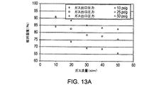
蒸気が水蒸気である図15に例示されるように、気化器の温度および流量を変更することによって蒸気濃度は気化器を通るパージガス流量に本質的に左右されない範囲に制御されることが可能である。いくつかのバージョンにおいて、蒸気濃度はパージガス混合物中の蒸気濃度の約5%未満、いくつかの実施形態では約1%未満、さらに別の実施形態では約0.5%未満に制御されることが可能である。図15に示されるように、本発明のバージョンにおける気化器は約40slm流量で約6314ppmの水蒸気濃度、約80slm流量で約6255ppmの水分濃度、および約120slm流量で約6286ppmの水分濃度を備えたパージガス混合物を供給することが可能である。この本質的に一定の水分濃度は気化器を通るパージガスの流量全体にわたって約0.5%未満で変化する。 As illustrated in FIG. 15 where the steam is water vapor, by changing the vaporizer temperature and flow rate, the vapor concentration can be controlled to a range that is essentially independent of the purge gas flow rate through the vaporizer. . In some versions, the vapor concentration may be controlled to be less than about 5% of the vapor concentration in the purge gas mixture, in some embodiments less than about 1%, and in other embodiments less than about 0.5%. Is possible. As shown in FIG. 15, the vaporizer in the version of the present invention has a purge gas with a water concentration of about 6314 ppm at a flow rate of about 40 slm, a water concentration of about 6255 ppm at a flow rate of about 80 slm, and a water concentration of about 6286 ppm at a flow rate of about 120 slm. It is possible to supply a mixture. This essentially constant moisture concentration varies by less than about 0.5% throughout the purge gas flow rate through the vaporizer.
パージガス混合物発生器120のいくつかのバージョンにおいて、発生器は流れの方向で精製器装置128、流量計127、バルブ125、減量器129、熱交換器126、および保湿器150を含むことがあり得る。
In some versions of the purge
パージガス用のガスの源はパージガス入口110を介して精製器装置128に供給されてもよい。例えば、CDA供給源(図示せず)からの圧縮乾燥空気(CDA)がパージガス入口110を介して精製器装置128に供給されてもよい。このCDAが精製器128によって精製される。精製器128は2つの並列の流量分岐128Aと128Bを含み、各々が流れの方向で自動バルブ1281または1282、および再生可能な精製デバイス1283または1284を含む。再生可能な精製デバイス1283および1284はそれぞれの精製デバイスを別々かつ独立して加熱し、それによって再生させるための加熱用素子を各々設けられる。例えば、一方の精製器は他方の精製器が再生処理されていてオフラインにある間にパージガスを作るために使用されてもよい。流量分岐は精製デバイス1283および1284の下流でガス純度センサ1286によって制御されることが可能な遮断バルブ1285に接続される。
A source of gas for the purge gas may be supplied to the
精製器は再生可能であるので、本システムは精製器がパージガスから除去された化合物で飽和状態になる場合にこれらを別々に再生させることによって長期間使用されることが可能である。再生可能な精製器はいずれの適切なタイプであってもよく、例えば再生可能なフィルタであってもよく、これが例えばチャコールフィルタ内で起こる非再生型化学処理とは対照的に吸着などの物理的処理、触媒、または別の方法によって汚染化合物または粒子をガスから外に除去する。概して、再生可能な精製器は有機材料を含まず、かつ再生可能な精製器は通常ではパージガスの汚染物質に物理的に結合するために適したゼオライト、酸化チタン、ガリウムまたはパラジウム化合物、またはその他を含めた金属などの材料を含む。好ましい精製器はMykrolis Corp.(現在ではEntegris,Inc.)から入手可能なAeronex InertまたはXCDA精製器(CE−70KF−I、O、またはN)などの不活性ガスおよび酸素と共存可能な精製器である。本発明のいくつかのバージョンにおいて、適切な精製器は1ppt未満の炭化水素、NOx、またはその他などといった汚染物質を伴うパージガスを供給する。 Since the purifier can be regenerated, the system can be used for extended periods of time by regenerating them separately when the purifier becomes saturated with compounds removed from the purge gas. Renewable purifiers can be of any suitable type, for example a reproducible filter, which is a physical such as adsorption, as opposed to non-regenerative chemical processing that occurs in, for example, a charcoal filter. Contaminating compounds or particles are removed out of the gas by treatment, catalyst, or another method. In general, renewable purifiers do not contain organic materials, and renewable purifiers typically contain zeolites, titanium oxide, gallium or palladium compounds, or other suitable for physically binding to purge gas contaminants. Includes materials such as metals included. A preferred purifier is Mykrolis Corp. A purifier that can coexist with inert gases and oxygen, such as the Aeronex Inert or XCDA purifier (CE-70KF-I, O, or N) available from (now Entegris, Inc.). In some versions of the invention, a suitable purifier provides a purge gas with contaminants such as less than 1 ppt hydrocarbon, NOx, or the like.
精製デバイス1283および1284は清浄乾燥空気(CDA)または他のガスが精製される精製状態と再生状態に交互に置かれてもよい。再生状態では精製デバイスはそれぞれの加熱用素子によって再生処理される。したがって、例えば精製デバイス1283がCDAを精製する間に精製デバイス1284が別個に独立して再生処理される。精製器装置128はしたがって、一定レベルのガス精製を維持しながら連続的に動作することができる。
The
自動バルブ1281および1282は対応する精製デバイス1283および1284の動作に対応して動作させられる。したがって、精製デバイス1283または1284が再生処理されるとき、対応するバルブ1281または1282が閉じられる。精製デバイス1283または1284が精製のために使用されるとき、対応するバルブ1281または1282が開かれる。
一実施形態では、精製済みCDAなどの精製されたガスは純度センサ1286によって制御される遮断バルブ1285を通される。精製済みCDAの純度が所定の閾値よりも下であると純度センサ1286は遮断バルブ1285を自動的に閉じる。したがって、不十分な純度レベルを伴うパージガスによるリソグラフィ用投影装置1の汚染は自動的に防止される。
In one embodiment, purified gas, such as purified CDA, is passed through a
精製済みCDAの流量は流量計127を介してモニタされることが可能である。流れを手動で遮断するためにバルブ125が使用されてもよい。減量器129は減量器の出口で安定した圧力を与え、したがって安定したパージガス圧力が(熱交換器126を介して)制限部143−145に供給されることができる。
The flow rate of purified CDA can be monitored via
熱交換器126は実質的に一定の温度で精製済みCDAを供給する。熱交換器126は特定の実施に適したガス温度を達成するために精製済みCDAなどの精製ガスから熱を抽出するかまたは熱を加える。リソグラフィ用投影装置においては、例えば安定した処理条件が使用され、したがって熱交換器が精製済みCDAの温度を安定させることで時間全体にわたってガスが一定または所定の狭い温度範囲である温度を有することができる。リソグラフィ用途においてパージガス出口でのパージガスにとって適した条件は、例えば20−30標準リットル毎分の流量、および/または約摂氏22度のパージガスの温度および/または30−60%の範囲の相対湿度であってもよい。しかしながら、本発明はこれらの条件に限定されず、これらのパラメータに関する別の値も本発明によるシステムにおいて同様に使用されることがあり得る。パージガスの温度を調節して気化器内の気化可能な液体からの蒸気の取り込みを変更するために熱交換器が使用されてもよい。
The
熱交換器126は制限部143−145を介してパージガス出口130−132に接続されてもよい。制限部143−145は、パージガス出口130−132の各々において望ましい一定のパージガス流量および圧力が得られるようにガス流量を制限するために使用されてもよい。パージガス出口においてパージガス圧力に関して適切な値は例えば100mbarであることもあり得る。パージガス出口131−132およびパージガス混合物出口130の各々において調節可能なガス流量を供給するために調節可能な制限部を使用することも同様に可能である。
The
気化器、例えば保湿器150は熱交換器の下流で制限部143とパージガス出口130との間に接続される。図1および図2の実例ではパージガス混合物出口130はウェハテーブルWTの近傍に設けられる。保湿器150は水分または水蒸気を精製済みCDAに添加し、したがってパージガス混合物を出口130に供給する。この実例では、1つの出口のみにおいてパージガス混合物が放出される。しかしながら、例えば複数のパージガス出口を別々の保湿器に接続することによって、または2つ以上の出口を同じ保湿器に接続することによって2つ以上のパージガス出口にパージガス混合物を放出することも同様に可能である。パージガス混合物発生器内で図3に示される位置とは異なる位置に保湿器などの気化器を設けることも同様に可能である。例えば、保湿器150はバルブ143とパージガス出口130との間ではなくパージガス混合物発生器120とバルブ143との間に置かれてもよい。保湿器150または他の気化器150が同様に流量制限部として作用すなわち動作してもよく、そのように所望されれば保湿器150に接続される制限部130が省略されることも可能である。
A vaporizer, such as a
保湿器150は、例えば図4に示されるように導入されてもよい。しかしながら、保湿器150が異なる形態で導入されることも同様に可能であり、例えばパージガスの流れの中に流体を蒸発させる気化器を含むこともあり得る。
The
図4に示された保湿器150は、例えば高純度の水などの気化可能な液体154で液面準位Aまで満たされる液体容器151を含む。ガス入口1521(これ以降は「湿潤ガス入口1521」)はマウンディングを液面準位Aよりも下に液体154中に沈めて設置される。別のガス入口1522(これ以降は「乾燥ガス入口1522」)はマウンディングを、液体容器151の一部であって液体154で満たされていない部分である液面準位Aの上に置いて設置される。ガス出口153は液体154よりも上の液体容器153の部分をパージガス供給システム100の他の部分と接続する。気化器のこのバージョンでは、パージガス、例えば精製済みの圧縮乾燥空気は湿潤ガス入口1521を介して液体容器151内に供給される。したがって、パージガスの泡159が液体154中に作り出される。浮力のせいで、泡159は図4に矢印Bで示されるように液体154中でマウンディングを過ぎた後に上向きに移動する。理論に縛られることを意図することなく、この上方向への移動の期間中に液体154からの水分が例えば拡散過程のせいで泡159に入る。したがって、泡159の中のパージガスは水分と混ぜ合わされる。液体の表面、すなわち液面準位Aにおいて、泡159はそのガス状内容物を液体容器151内で液体154よりも上に存在する(複数の)ガスに供給する。結果として生じるパージガス混合物はガス出口153を経由して容器から放出される。
The
湿潤ガス入口1521は液体容器151の外側で図3のパージガス混合物発生器120などのパージガス供給デバイス(図示せず)に接続される外側端部を備えた管状素子であってもよい。蒸気含有ガスまたは湿潤ガス入口1521は液体容器151の内側に配置される内側端部において小さい、例えば0.5ミクロンの通路を備えたフィルタ素子1525を設けられる。フィルタ素子1525は少なくとも部分的に、この実施形態では全体的に液体154中に設置される。したがって、湿潤ガス入口1521は多量の極めて小さいパージガスの泡を発生させる。その小さいサイズ(例えば、約0.5ミクロン)が原因で、泡159は比較的短い時間的期間、すなわち液体154を通る比較的短い移動距離で飽和状態に加湿される。
The
乾燥ガス入口1522は湿潤ガス入口1521のフィルタ素子と同様のフィルタ素子1524を設けられる。それにより、湿潤ガス入口1521および乾燥ガス入口1522を通るガス流は実質的に同様であり、パージガス混合物中の水分の量は泡159が液体154を離れる瞬間の泡159内の水分の量の実質的に半分である。すなわち、泡159が水分で飽和されていれば、すなわち相対湿度(Rh)100%であれば、パージガス混合物は50%Rhを有する。しかしながら、湿潤ガス入口1521と乾燥ガス入口1522それぞれを経由して液体容器の中に流れ込むガスの異なる比を与え、それにより、相対湿度を約0と約100%Rhとの間で調節することも同様に可能である。
The
ガス出口153はその内側端部に微細な、例えば0.003ミクロンのメッシュのフィルタ1526を設けられ、このフィルタは液体容器151から流出するガスから粒子および微小液滴を濾過するために使用されることが可能である。したがって、パージガス混合物が供給される表面のそのような粒子による汚染は削減される。
The
パージガス混合物中の水分の相対量は多様な方式で制御されることが可能である。例えば、ガスの泡が移動する液体の高さなどといった液体容器151のパラメータが制御されてもよい。また、例えば、湿潤ガス入口1521を経由して作り出される水分を伴うパージガスの量に相対した乾燥ガス入口1522を経由して容器151内に運ばれる水分を伴わないパージガスの量が制御されてもよい。制御される液体容器151のパラメータは、例えば、内側温度、流量、圧力、液中のパージガスの滞留時間のうちの1つまたは複数であってもよい。
The relative amount of moisture in the purge gas mixture can be controlled in a variety of ways. For example, parameters of the
温度は、例えばガス中に存在し得る蒸気状の水分の飽和量に影響を有することが知られている。温度を制御するために、液体容器151は加熱用素子を設けられてもよく、この素子が例えば温度測定用デバイスによって供給される液体容器の内側の温度を表す温度信号に応答して制御デバイスまたは制御器によって制御される。
Temperature is known to have an effect on the amount of vaporous water saturation that may be present in a gas, for example. In order to control the temperature, the
気化可能な液体154中での泡の滞留時間は湿潤ガス入口1521を経由してガスの泡が液体に入れられる位置を調節することによって変更されることができる。例えば、フィルタ1525がさらに液体154の中に位置付けられると、泡が液面準位Aまで移動しなければならない距離が増大させられ、それゆえに滞留時間も同様に増える。ガスの泡が液体154中に長く存在するにつれて、ガスの中に吸収されることができる水蒸気などの蒸気は多くなる。したがって、この滞留時間を変更することによってガスの蒸気含有量、例えば湿度が適応させられることが可能である。
The residence time of the bubbles in the vaporizable liquid 154 can be changed by adjusting the position where the gas bubbles are put into the liquid via the
保湿デバイス150はさらに制御デバイス157を設けられ、これを介してパージガス混合物中の水蒸気などの蒸気の量が制御されることが可能である。例えば、制御デバイス157は水分制御連絡部1571で乾燥ガス入口1522の制御バルブ1523に接続され、このバルブを介して乾燥ガス入口1522に供給されるパージガスの流量が制御されることが可能であり、したがって水分添加されたガスの量に相対した乾燥パージガスの量が制御されることが可能である。
The
制御デバイス157はさらに液体容器151内にある液体154の量を制御する。制御デバイス157は液体制御連絡部1572で液体供給部156の制御バルブ1561に接続され、オーバーフロー連絡部1573でガス出口153の制御バルブ1531に接続される。液面準位測定デバイス158が制御デバイス157に情報伝達可能に接続される。液面準位測定デバイス158は液体容器151内の液面準位の特性を表す液面準位信号を制御デバイス157に供給する。制御デバイス157は気化可能な液体の液面準位信号に応答して制御バルブ1561および制御バルブ1531を操作する。
The
この実例において、液面準位測定デバイス158は液体容器151の底部に対して適切で異なる高さに配置された3個のフロートスイッチ1581−1583を含む。最下位のフロートスイッチ1581は底部に最も近く配置される。最下位フロートスイッチ1581は液面準位Aが最下位フロートスイッチ1581またはそれよりも下にあるとき空容器信号を制御デバイス157に供給する。空容器信号に応答して、制御デバイス157は制御バルブ1561を開き、容器に液体が自動的に供給される。
In this example, the liquid
中位にあるフロートスイッチ1582は液面準位Aがこのフロースイッチ1582の高さに到達する場合に満充填信号を供給する。制御デバイス157は満充填信号に応答して制御バルブ1561を閉じ、それによって液体供給をオフに切り換える。
The
最上位フロートスイッチ1583は底部から最も遠くに配置される。最上位フロートスイッチ1583は液面準位Aが最上位フロートスイッチ1581またはそれよりも上にある場合に過充填信号を制御デバイス157に供給する。過充填に応答して、制御デバイス157はリソグラフィ用投影装置1の他の部分の中に液体が漏れるのを防止するためにガス出口153の制御バルブ1531を遮断する。
The
20%以上、例えば25%以上などの相対湿度を備えたパージガス混合物はフォトレジストの性能に対して特に良好な結果を提供する。さらに、25%以上で70%未満、例えば60%などの相対湿度を備えたパージガス混合物はリソグラフィ用投影装置内の測定システムの精度に対して良好な予防効果を有する。さらに、リソグラフィ用投影装置を取り巻く空間、例えばクリーンルームの湿度と同様である湿度、例えば約40%が最適の結果を提供することが見出された。 A purge gas mixture with a relative humidity of 20% or more, such as 25% or more, provides particularly good results for the performance of the photoresist. Furthermore, a purge gas mixture with a relative humidity of more than 25% and less than 70%, for example 60%, has a good preventive effect on the accuracy of the measuring system in the lithographic projection apparatus. Furthermore, it has been found that the space surrounding the lithographic projection apparatus, for example a humidity similar to that of a clean room, for example about 40%, provides optimal results.
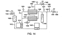
本発明の、例えばさらに高いガス流量、向上した蒸気濃度制御、または単純化した操作が有利であるいくつかの実施形態では、気化器はハウジングおよびパージガス流を含む第1の領域および気化可能な液体を含む第2の領域を含んでもよく、第1と第2の領域は液体の浸入に対して実質的に抵抗性であるガス透過性ホローファイバ膜によって分離される。そのような気化器はパージガスに液体蒸気を供給することでパージガス混合物を形成するために利用されてもよい。いくつかの実施形態においてこの気化器はハウジングおよびパージガス流を含む第1の領域および水を含む第2の領域を含む保湿器であり、第1と第2の領域は水の浸入に対して実質的に抵抗性であるガス透過性膜によって分離される。 In some embodiments of the present invention where, for example, higher gas flow rates, improved vapor concentration control, or simplified operation is advantageous, the vaporizer includes a first region including a housing and a purge gas stream and a vaporizable liquid. The first and second regions may be separated by a gas permeable hollow fiber membrane that is substantially resistant to liquid ingress. Such a vaporizer may be utilized to form a purge gas mixture by supplying liquid vapor to the purge gas. In some embodiments, the vaporizer is a moisturizer that includes a housing and a first region that includes a purge gas stream and a second region that includes water, wherein the first and second regions are substantially resistant to water ingress. It is separated by a gas permeable membrane that is electrically resistant.
気化器の膜にとって適した材料はポリ(テトラフルオロエチレン−コ−ペルフルオロ−3,6−ジオキサ−4−メチル−7−オクテンスルホン酸)などの熱可塑性ポリマーおよびポリテトラフルオロエチレンなどのペルフルオロ化合物ポリマーを含む。ペルフルオロ化合物ポリマーなどの非湿潤性のポリマーが特に好ましく、とりわけ高圧流体との使用に適していて無機酸化物(例えばSOxおよびNOxであって、ここでxは1−3の整数である)を実質的に含まないポリマーが好ましい。膜は折り畳みまたはプリーツをつけられることが可能なシートであってもよく、またはホローファイバを形成するように対向する側を連結されてもよい。ホローファイバ膜は本発明のいくつかのバージョンでは押し出し成形の多孔質ホローファイバであってもよい。いずれかの封止剤、注封樹脂、または膜をハウジングに連結するために使用される接着剤と併用される膜は通常の動作条件下(例えば30psig以下の圧力)で液体がパージガスの中に浸透するのを防止し、かつ気体放出を削減または除去する。この膜はパージガスおよび水などの気化可能な液体に接触する膜の表面積を最大にし、かつ膜の体積を最小にするように構成されることが好ましい。保湿器は下記で記述されるように1つのデバイス当たり複数の膜を含むこともあり得る。 Suitable materials for the vaporizer membrane are thermoplastic polymers such as poly (tetrafluoroethylene-co-perfluoro-3,6-dioxa-4-methyl-7-octene sulfonic acid) and perfluoro compound polymers such as polytetrafluoroethylene. including. Non-wetting polymers such as perfluoro compound polymers are particularly preferred, especially suitable for use with high pressure fluids and inorganic oxides (eg SO x and NO x , where x is an integer of 1-3) Polymers substantially free of are preferred. The membrane may be a sheet that can be folded or pleated, or connected on opposite sides to form a hollow fiber. The hollow fiber membrane may be an extruded porous hollow fiber in some versions of the invention. Any sealant, potting resin, or membrane used in conjunction with the adhesive used to connect the membrane to the housing will allow the liquid to enter the purge gas under normal operating conditions (eg, pressure below 30 psig). Prevent permeation and reduce or eliminate outgassing. The membrane is preferably configured to maximize the membrane surface area in contact with vaporizable liquids such as purge gas and water and minimize the membrane volume. The moisturizer may include multiple membranes per device as described below.
管内のホローファイバおよびシェル構造を備えた気化器が使用されてもよい。いくつかの実施形態ではこの気化器はキャリヤガスに水蒸気を添加するために使用され、保湿器と呼ばれることも可能である。例えば、ホローファイバ膜を有する気化器または保湿器は通常ではa)第1の端部と第2の端部を有し、外側表面と内側表面を有する複数のガス透過性ホローファイバ膜の束を含み、内側表面は第1の領域および第2の領域の一方を包含し、b)この束の各々の端部が液密のシールで注封されて周囲にハウジングを備えた端部構造を形成し、ファイバの端部は流体の流れに開放され、c)このハウジングが内壁と外壁を有し、この内壁が内壁とホローファイバ膜との間に第1の領域および第2の領域の他方を規定し、d)このハウジングがパージガス供給源に接続されたパージガス入口とパージガス混合物出口を有し、e)このハウジングが気化可能液体供給源に接続された気化可能液体入口と気化可能液体出口を有し、パージガス入口がこの束の第1の端部に接続されてパージガス混合物出口がこの束の第2の端部に接続されるかまたは気化可能液体入口がこの束の第1の端部に接続されて気化可能液体出口がこの束の第2の端部に接続される。いくつかの実施形態では気化可能液体は水である。 A vaporizer with a hollow fiber and shell structure in the tube may be used. In some embodiments, this vaporizer is used to add water vapor to the carrier gas and can also be referred to as a moisturizer. For example, a vaporizer or moisturizer having a hollow fiber membrane typically has a) a bundle of a plurality of gas permeable hollow fiber membranes having a first end and a second end and having an outer surface and an inner surface. The inner surface includes one of the first region and the second region, and b) each end of the bundle is potted with a liquid tight seal to form an end structure with a housing around it The end of the fiber is open to fluid flow; c) the housing has an inner wall and an outer wall, the inner wall interposing the other of the first region and the second region between the inner wall and the hollow fiber membrane. D) the housing has a purge gas inlet and a purge gas mixture outlet connected to the purge gas supply; e) the housing has a vaporizable liquid inlet and a vaporizable liquid outlet connected to the vaporizable liquid supply. Purge gas inlet The purge gas mixture outlet is connected to the first end of the bundle and the vaporizable liquid inlet is connected to the second end of the bundle or the vaporizable liquid outlet is connected to the first end of the bundle. Is connected to the second end of the bundle. In some embodiments, the vaporizable liquid is water.
気化器または保湿器として使用することに概して適しているホローファイバ膜を備えたデバイスは通常では膜コンタクタと称され、米国特許第6149817号明細書、第6235641号明細書、第6309550号明細書、第6402818号明細書、第6474628号明細書、第6616841号明細書、第6669177号明細書、および第6702941号明細書に記述されており、これらの内容は本願明細書に参照で組み入れられる。膜コンタクタの多くは液体(例えば水)にガスを添加することまたはガスを取り除くことに有用であると前述の特許明細書に記述されているが、本願出願人らは液体から生じる蒸気が削減された汚染物質、または約1ppt未満追加された汚染物質を伴ってパージガス流に添加されるような気化器として、膜コンタクタが概して操作されることが可能であることを発見した。パージガス混合物発生器内のこの気化器はパージガスへの1pptを超える汚染物質に寄与することなく大流量でパージガスに蒸気を添加する。この気化器の排出物は例えば1ppt未満の非メタン系炭化水素および1ppt未満の硫黄化合物を含む。適切な膜気化器は精製器によって形成されるパージガスの完全性に影響を与えることなく精製器の下流で使用されることが可能である。多孔質膜気化器の清浄度を特性化するためにガスクロマトグラフィ/パルス式炎イオン化検出器、APIMS、または他の追跡技術が使用されてもよい。汚染を低減するために作製およびまたは処理され、保湿器として使用するために適切にされることができる膜コントラクタの特定の実例はPall Corporationによって市販されているInfuzor(登録商標)膜コントラクタモジュール、Membrana−Charlotteによって市販されているLiqui−Cel(登録商標)、およびPermaPure LLCによって市販されているNafion(登録商標)Membrane燃料電池式加湿器を含む。 Devices with hollow fiber membranes that are generally suitable for use as vaporizers or moisturizers are commonly referred to as membrane contactors and are described in US Pat. Nos. 6,149,817, 6,235,641, 6,309,550, Nos. 6,402,818, 6,474,628, 6,668,841, 6,669,177, and 6,702,941, the contents of which are incorporated herein by reference. Although many of the membrane contactors are described in the aforementioned patent specifications as useful for adding or removing gas from a liquid (eg, water), Applicants have reduced the vapor generated from the liquid. It has been discovered that membrane contactors can generally be operated as vaporizers that are added to a purge gas stream with additional contaminants, or contaminants added less than about 1 ppt. This vaporizer in the purge gas mixture generator adds steam to the purge gas at a high flow rate without contributing more than 1 ppt of contaminants to the purge gas. The vaporizer effluent contains, for example, less than 1 ppt of non-methane hydrocarbons and less than 1 ppt of sulfur compounds. A suitable film vaporizer can be used downstream of the purifier without affecting the integrity of the purge gas formed by the purifier. Gas chromatography / pulse flame ionization detectors, APIMS, or other tracking techniques may be used to characterize the cleanliness of the porous membrane vaporizer. A specific example of a membrane contractor that is made and / or processed to reduce contamination and can be made suitable for use as a moisturizer is the Infuzor® membrane contractor module marketed by Pall Corporation , Liqui-Cel® marketed by Membrana-Charlotte, and Nafion® Membrane fuel cell humidifier marketed by PermaPure LLC.
特定の好ましい気化器または保湿器の概略図が図5に示されており、これの市販の実施形態はマサチューセッツ州ビルリカのMykrolis(登録商標)Corporation(現在はEntegris,Inc.)によって市販されているpHasor(登録商標)II Membrane Contractorである。図5に例示されるように、流体1がファイバの管腔3を通って保湿器2に入り、保湿器2の内部を横切り、その一方で管腔3では流体1は膜によって流体4から隔てられ、接続部40でファイバの管腔を通ってコンタクタ2を出る。流体4は接続部30を通ってハウジングに入り、ハウジングの内壁とファイバの外径との間の空間を実質的に満たし、接続部20を通って出る。
A schematic diagram of a particular preferred vaporizer or moisturizer is shown in FIG. 5 and a commercially available embodiment thereof is marketed by Mykroris Corporation (now Entegris, Inc.) of Billerica, Massachusetts. pHasor® II Membrane Contractor. As illustrated in FIG. 5, fluid 1 enters the
本発明の気化器または保湿器のバージョンに使用されるガス透過性ホローファイバ膜は通常では以下、すなわちa)多孔質表皮の内側表面、多孔質の外側表面、および間の多孔質支持構造を有するホローファイバ膜、b)無孔質表皮の内側表面、多孔質の外側表面、および間の多孔質支持構造を有するホローファイバ膜、c)多孔質表皮の外側表面、多孔質の内側表面、および間の多孔質支持構造を有するホローファイバ膜、またはd)無孔質表皮の外側表面、多孔質の内側表面、および間の多孔質支持構造を有するホローファイバ膜のうちの1つである。これらのホローファイバ膜は約350ミクロンから約1450ミクロンの外径を有してもよい。 The gas permeable hollow fiber membrane used in the vaporizer or moisturizer version of the present invention typically has the following: a) the inner surface of the porous skin, the outer surface of the porous, and the porous support structure in between A hollow fiber membrane, b) a hollow fiber membrane having a porous support structure between the inner surface of the nonporous skin, a porous outer surface, and a porous support structure, c) an outer surface of the porous skin, a porous inner surface, and a gap Or a hollow fiber membrane having a porous support structure in between and an outer surface of a nonporous skin, a porous inner surface, and a porous support structure in between. These hollow fiber membranes may have an outer diameter of about 350 microns to about 1450 microns.
これらのホローファイバ膜が多孔質表皮の内側表面、多孔質の外側表面、および間の多孔質支持構造を有するホローファイバ膜または多孔質表皮の外側表面、多孔質の内側表面、および間の多孔質支持構造を有するホローファイバ膜であるとき、多孔質表皮の表面の孔は直径または最大外観で約0.001ミクロンから約0.005ミクロンであることが好ましい。表皮表面の孔は液体の流れに面することが好ましい。 These hollow fiber membranes have an inner surface of the porous skin, a porous outer surface, and a hollow fiber membrane or outer surface of the porous skin having a porous support structure therebetween, a porous inner surface, and a porous between When a hollow fiber membrane having a support structure, the pores on the surface of the porous skin are preferably about 0.001 microns to about 0.005 microns in diameter or maximum appearance. The pores on the skin surface preferably face the liquid flow.
これらのホローファイバ膜に適した材料はポリ(テトラフルオロエチレン−コ−ペルフルオロ(アルキルビニルエーテル))(ポリ(PTFE−CO−PFVAE))、ポリ(テトラフルオロエチレン−コ−ヘキサフルオロプロピレン)(FEP)またはこれらの混合物などといったペルフルオロ化合物の熱可塑性ポリマーを含み、なぜならばこれらのポリマーは厳しい使用条件によって悪影響を受けないからである。PFA Teflon(登録商標)はポリ(PTFE−CO−PFVAE))の一例であり、アルキルは主として、または完全にプロピル基である。FEP Teflon(登録商標)はポリ(FEP)の一例である。両方がDuPontによって製造されている。Neoflon(商標)PFA(Daikin Industries)はDuPontのPFA Teflon(登録商標)に類似したポリマーである。アルキル基が主としてメチル基であるポリ(PTFE−CO−PFVAE)は米国特許第5463006号明細書に記述されており、その内容は本願明細書に参照で組み入れられる。好ましいポリマーはニュージャージー州ThorofareのAusimont USA,Inc.から入手可能なHyflon(登録商標)ポリ(PTFE−CO−PFVAE)620である。これらのポリマーをホローファイバ膜に形成する方法は米国特許第6582496号明細書および第4902456号明細書に開示されており、その内容は本願明細書に参照で組み入れられる。 Suitable materials for these hollow fiber membranes are poly (tetrafluoroethylene-co-perfluoro (alkyl vinyl ether)) (poly (PTFE-CO-PFVAE)), poly (tetrafluoroethylene-co-hexafluoropropylene) (FEP) Or thermoplastic polymers of perfluoro compounds such as mixtures thereof, because these polymers are not adversely affected by harsh use conditions. PFA Teflon® is an example of poly (PTFE-CO-PFVAE)), where the alkyl is predominantly or completely propyl groups. FEP Teflon® is an example of poly (FEP). Both are manufactured by DuPont. Neoflon ™ PFA (Dakin Industries) is a polymer similar to DuPont's PFA Teflon®. Poly (PTFE-CO-PFVAE) in which the alkyl group is primarily a methyl group is described in US Pat. No. 5,463,006, the contents of which are hereby incorporated by reference. A preferred polymer is Ausimont USA, Inc. of Thorofare, NJ. Hyflon® poly (PTFE-CO-PFVAE) 620 available from Methods for forming these polymers into hollow fiber membranes are disclosed in US Pat. Nos. 6,582,496 and 4,902,456, the contents of which are hereby incorporated by reference.
注封は各々のファイバの周りに液密シールを有するチューブシートを形成する工程である。このチューブシートまたはポットは保湿器の内部を環境から分離する。一体型端部構造を作り出すためにこのポットがハウジング容器に熱接着される。一体型端部構造はファイバとこのポットがハウジングに接着されて単にペルフルオロ化合物の熱可塑性材料のみから成る単一の実体を形成するときに得られる。この一体型端部構造は注封された端部に包含されるファイバ束の部分、このポットおよびペルフルオロ化合物の熱可塑性ハウジングの端部部分を含み、ハウジングの内側表面はこのポットと一致して(congruent)このポットに接着される。一体型構造を形成することによって、一層頑丈な気化器または保湿器が作り出され、ポットとハウジングの界面で漏れを生じること、または別の場合で不具合を生じることは殆どない。さらに、一体型端部構造を形成することは、ファイバを定位置に接着するためにエポキシなどの接着剤を使用する必要性を回避する。そのような接着剤は通常では揮発性の炭化水素を含み、これが気化器または保湿器を通って流れるパージガスを汚染させる。例えば、Perma Pureによって市販されているLiqui−cel保湿器を使用して加湿されたパージガスは著しくエポキシの臭いがし、これは明らかにパージガス中の受容不可能な炭化水素含有量、おそらく数百ppmを示している。注封および接着処理は1999年1月29日に提出された米国特許出願第60/117853号明細書に記述された方法の改作であって米国特許第6582496号明細書に開示されており、これらの教示は本願明細書に参照で組み入れられる。ホローファイバ膜の束は、束の第1と第2の端部が液密のペルフルオロ化合物の熱可塑性シールで注封されることで周囲のペルフルオロ化合物の熱可塑性ハウジングを備えた第1と第2の端部の両方を含む単一の一体型端部構造を形成するように調製されることが好ましく、これらの端部のファイバは別々に流体の流れに開放されている。 Potting is the process of forming a tube sheet having a liquid tight seal around each fiber. This tube sheet or pot separates the interior of the moisturizer from the environment. The pot is heat bonded to the housing container to create an integral end structure. An integral end structure is obtained when the fiber and the pot are bonded to the housing to form a single entity consisting solely of a perfluoroplastic thermoplastic material. The unitary end structure includes the portion of the fiber bundle contained in the potted end, the pot and the end portion of the perfluoro compound thermoplastic housing, the inner surface of the housing being coincident with the pot ( glue) glued to this pot. By forming a monolithic structure, a more robust vaporizer or moisturizer is created, with little leakage or otherwise failure at the pot-housing interface. Furthermore, forming an integral end structure avoids the need to use an adhesive such as an epoxy to bond the fiber in place. Such adhesives usually contain volatile hydrocarbons that contaminate the purge gas flowing through the vaporizer or moisturizer. For example, purge gas humidified using a Liqui-cel moisturizer marketed by Perma Pure has a significant epoxy odor, which clearly represents an unacceptable hydrocarbon content in the purge gas, perhaps several hundred ppm Is shown. The potting and bonding process is a modification of the method described in U.S. Patent Application No. 60 / 117,853 filed Jan. 29, 1999 and is disclosed in U.S. Pat. No. 6,582,496. The teachings of which are incorporated herein by reference. The bundle of hollow fiber membranes includes a first and a second end provided with a surrounding perfluoro compound thermoplastic housing by potting the first and second ends of the bundle with a liquid-tight perfluoro compound thermoplastic seal. Are preferably prepared to form a single unitary end structure that includes both ends of which are separately open to fluid flow.
本発明の1つのバージョンはパージガスに蒸気を添加する装置である。この装置は1つまたは複数の再生可能な精製器と流体連絡している源泉ガス入口、および精製器からのパージガス出口であって気化器のパージガス入口と流体連絡している出口を含んでもよい。この精製器は独立して再生可能であってもよく、精製器への源泉ガス入口から汚染物質を取り除いてパージガスを形成することができる。気化器はハウジングおよび1つまたは複数の微小孔性ホローファイバ膜を含んでもよい。ハウジングはパージガス入口、および微小孔性ホローファイバの第1の側と流体連絡しているパージガス混合物出口を有する。このハウジングは気化可能液体のための入口、および微小孔性ホローファイバの第2の側と流体連絡している気化可能液体のための出口を有する。微小孔性ホローファイバ膜はリソグラフィ用投影システム内の光学部品の光学特性を劣化させる汚染物質の1ppb未満の濃度、いくつかの実施形態では100ppt未満の濃度を気化可能液体の気化器から出る蒸気に与える。気化器はそのような汚染物質を低減または除去するために洗浄または処理されてもよい。この微小孔性ホローファイバは気化可能液体による液体浸入に抵抗性である。 One version of the invention is an apparatus for adding steam to a purge gas. The apparatus may include a source gas inlet in fluid communication with one or more renewable purifiers and a purge gas outlet from the purifier and in fluid communication with the vaporizer purge gas inlet. The purifier may be independently recyclable, and contaminants can be removed from the source gas inlet to the purifier to form a purge gas. The vaporizer may include a housing and one or more microporous hollow fiber membranes. The housing has a purge gas inlet and a purge gas mixture outlet in fluid communication with the first side of the microporous hollow fiber. The housing has an inlet for the vaporizable liquid and an outlet for the vaporizable liquid in fluid communication with the second side of the microporous hollow fiber. The microporous hollow fiber membrane provides a concentration of less than 1 ppb of contaminants that degrade the optical properties of optical components in a lithographic projection system, and in some embodiments, a concentration of less than 100 ppt, to the vapor exiting the vaporizer liquid vaporizer. give. The vaporizer may be cleaned or treated to reduce or remove such contaminants. This microporous hollow fiber is resistant to liquid penetration by a vaporizable liquid.
この装置はさらに、気化器、パージガス入口、パージガス混合物出口、またはこれらの組合せの温度を1つまたは複数の設定点範囲内に維持する温度調節システムを含んでもよい。この温度調節システムは1つまたは複数の温度測定デバイス、装置の1つまたは複数のゾーンまたは領域の温度を変更することができる1つまたは複数の熱交換器、および制御器を含んでもよい。この制御器は温度測定デバイスから温度入力を受け取り、1つまたは複数の熱交換器の動作を制御することによって装置の温度を変更する。これらの熱交換器は、限定はされないがヒーター、冷却装置、ペルチェ冷却器、ファンまたは他のデバイスを含んでもよい。この温度調節システムは気化器、パージガス、パージガス混合物、またはこれらのいずれかの組合せの温度を約±5℃以下、いくつかの実施形態では±1℃以下、さらに別の実施形態では±0.5℃以下の温度範囲内の設定点温度に維持することが可能である。この温度調節システムは、蒸気の凝縮が低減または除去されるようにパージガス混合物を蒸気の凝縮温度よりも上に維持することが可能である。いくつかの実施形態では、この温度調節システムはパージガス混合物中の蒸気の温度を蒸気の凝縮温度よりも上に約±1℃以下の温度範囲で維持することが可能である。この温度調節システムはパージガス混合物、パージガス中の蒸気の濃度が5%未満、いくつかの実施形態では1%未満、さらに別のバージョンでは0.5%未満で変動する濃度を有するように装置の温度を維持することが可能である。この温度調節システムは装置内の温度勾配を維持することが可能である。装置の温度を維持することによって、この温度調節システムは本質的に一定の蒸気濃度を提供する。いくつかのバージョンではこの温度調節システムはパージガス混合物の温度を多様なパージガス流量において本質的に一定の温度に維持する。 The apparatus may further include a temperature regulation system that maintains the temperature of the vaporizer, purge gas inlet, purge gas mixture outlet, or a combination thereof within one or more set point ranges. The temperature regulation system may include one or more temperature measurement devices, one or more heat exchangers that can change the temperature of one or more zones or regions of the apparatus, and a controller. The controller receives a temperature input from a temperature measuring device and changes the temperature of the apparatus by controlling the operation of one or more heat exchangers. These heat exchangers may include, but are not limited to, heaters, chillers, Peltier coolers, fans or other devices. The temperature control system provides a temperature of the vaporizer, purge gas, purge gas mixture, or any combination thereof of about ± 5 ° C. or lower, in some embodiments ± 1 ° C. or lower, and in other embodiments ± 0.5 ° C. It is possible to maintain the set point temperature within a temperature range of ℃ or less. The temperature control system can maintain the purge gas mixture above the vapor condensation temperature so that vapor condensation is reduced or eliminated. In some embodiments, the temperature control system is capable of maintaining the temperature of the vapor in the purge gas mixture in a temperature range of about ± 1 ° C. or less above the vapor condensation temperature. The temperature control system is configured so that the temperature of the apparatus is such that the concentration of the purge gas mixture, the vapor concentration in the purge gas varies less than 5%, in some embodiments less than 1%, and in other versions less than 0.5%. Can be maintained. This temperature control system can maintain a temperature gradient within the device. By maintaining the temperature of the device, the temperature control system provides an essentially constant vapor concentration. In some versions, the temperature control system maintains the temperature of the purge gas mixture at an essentially constant temperature at various purge gas flow rates.
この装置は、微小孔性ホローファイバ内の気化可能液体中でのパージガスの泡の形成を阻止するように、および5%未満、いくつかの実施形態では1%未満、さらに別のバージョンでは0.5%未満で変動するパージガス混合物中の蒸気濃度を提供するように気化可能液体の圧力、パージガスの圧力、またはこれらのいずれかの組合せを維持する圧力調節システムを含んでもよい。この圧力調節システムは、その供給圧力が例えば加圧ガスまたはポンプによって変更されることが可能である気化可能流体の加圧源を含んでもよい。この圧力調節システムは圧力トランスデューサ、絞り弁、および気化器内のホローファイバ多孔質膜の一方の側で気化可能液体の圧力を測定および変更するための制御器を含んでもよい。この圧力調節システムは1つまたは複数の圧力トランスデューサ、絞り弁、および気化器内の多孔質ホローファイバの第2の側と接触しているパージガスまたはパージガス混合物の圧力を測定および変更するための制御器を含んでもよい。この圧力調節システムはパージガスまたはパージガス混合物の圧力を維持すること、および気化可能液体中のパージガスの泡の形成を阻止することが可能である。この装置のいくつかのバージョンでは圧力制御システムは気化可能液体の圧力をパージガスの圧力よりも約5psi以上高く維持する。この圧力調節システムは圧力制御器および背圧調節器を含んでもよい。 The apparatus is designed to prevent the formation of purge gas bubbles in the vaporizable liquid in the microporous hollow fiber and less than 5%, in some embodiments less than 1%, and in other versions, 0.1%. A pressure regulation system may be included that maintains the vaporizable liquid pressure, purge gas pressure, or any combination thereof to provide a vapor concentration in the purge gas mixture that varies less than 5%. The pressure regulation system may include a pressurized source of vaporizable fluid whose supply pressure can be changed, for example, by pressurized gas or a pump. The pressure regulation system may include a pressure transducer, a throttle valve, and a controller for measuring and changing the pressure of the vaporizable liquid on one side of the hollow fiber porous membrane in the vaporizer. The pressure regulation system includes a pressure transducer, a throttle valve, and a controller for measuring and changing the pressure of the purge gas or purge gas mixture in contact with the second side of the porous hollow fiber in the vaporizer. May be included. This pressure regulation system is capable of maintaining the pressure of the purge gas or purge gas mixture and preventing the formation of purge gas bubbles in the vaporizable liquid. In some versions of the apparatus, the pressure control system maintains the vaporizable liquid pressure at about 5 psi or more above the purge gas pressure. The pressure regulation system may include a pressure controller and a back pressure regulator.
本発明の実施形態における装置はパージガス、希釈ガスの流量、装置から出るパージガス混合物の流量、またはこれらのいずれかの組合せを維持する流量制御システムを含んでもよい。この流量制御システムは1つまたは複数のマスフローコントローラ、1つまたは複数の蒸気濃度センサ、および制御器を含んでもよい。蒸気飽和設定点の蒸気の濃度または画分に基づいて制御器が蒸気センサから濃度出力を取り出し、パージガスとパージガス混合物の混合を変更することで望ましい、または設定点の蒸気濃度を有する希釈済みパージガス混合物を作り出してもよい。この流量制御システムは5%未満、いくつかの実施形態では1%未満、さらに別のバージョンでは0.5%未満で変動するパージガス混合物中の蒸気濃度を提供することが可能である。 The apparatus in embodiments of the present invention may include a flow control system that maintains a purge gas, dilution gas flow, purge gas mixture flow out of the apparatus, or any combination thereof. The flow control system may include one or more mass flow controllers, one or more vapor concentration sensors, and a controller. A diluted purge gas mixture having a desired or set point vapor concentration, where the controller retrieves the concentration output from the vapor sensor based on the vapor concentration or fraction at the vapor saturation set point and alters the purge gas and purge gas mixture mixing May be produced. This flow control system can provide a vapor concentration in the purge gas mixture that varies by less than 5%, in some embodiments less than 1%, and in other versions less than 0.5%.
この装置は1ppb未満、いくつかのバージョンでは1ppt未満の揮発性不純物を有するパージガス混合物または希釈済みのパージガス混合物を作ることが可能である。本発明のいくつかのバージョンでは、パージガス混合物は約20slmよりも大きいパージガス流量において、リソグラフィ用投影システムまたは他の供給点の温度および圧力でパージガスを飽和させる蒸気の量の約20%よりも多い気化器からのパージガス混合物中の液体蒸気の量で形成されることもあり得る。パージガス混合物中の蒸気の組成または濃度は装置内の温度、圧力、流量、またはこれらのいずれかの組合せを制御することによって変更されることが可能である。パージガス混合物中の蒸気の濃度は、パージガスを気化器のパージガス混合物出口から出るパージガス混合物と混ぜ合わせる工程または作用によって、追加のパージガスによる希釈によってさらに変更されることが可能である。このパージガス混合物または希釈済みパージガス混合物は蒸気含有パージガス混合物を液体トラップに通し、液体を取り除く作用によってさらに処理されることもあり得る。 The apparatus is capable of producing a purge gas mixture or a diluted purge gas mixture having volatile impurities of less than 1 ppb, and in some versions less than 1 ppt. In some versions of the invention, the purge gas mixture vaporizes greater than about 20% of the amount of vapor that saturates the purge gas at the temperature and pressure of the lithographic projection system or other supply point at a purge gas flow rate greater than about 20 slm. It may also be formed by the amount of liquid vapor in the purge gas mixture from the vessel. The composition or concentration of the vapor in the purge gas mixture can be varied by controlling the temperature, pressure, flow rate, or any combination thereof in the apparatus. The concentration of the vapor in the purge gas mixture can be further altered by dilution with additional purge gas by the process or action of mixing the purge gas with the purge gas mixture exiting the vaporizer purge gas mixture outlet. This purge gas mixture or diluted purge gas mixture may be further processed by the action of passing the vapor-containing purge gas mixture through a liquid trap and removing the liquid.
気化可能流体は絞り弁を使用して加圧源からホローファイバに供給されることも可能である。場合によっては気化可能流体は再循環ループ内を流れる気化可能液体またはデッドエンド供給で気化器の中に供給されてもよい。例えば、気化可能液体が温度制御された容器内にあってポンプによって気化器の中に供給され、残りのいずれの気化可能液体もさらなる加熱のために容器に戻されてもよい。いくつかのバージョンではコンタクタの液体側の出口は閉じられ、気化可能流体はパージガスによって気化させられると加圧源から気化器に供給されてもよい。 The vaporizable fluid can also be supplied to the hollow fiber from a pressurized source using a throttle valve. In some cases, the vaporizable fluid may be supplied into the vaporizer with a vaporizable liquid or dead-end supply flowing through the recirculation loop. For example, the vaporizable liquid may be in a temperature controlled container and supplied by a pump into the vaporizer, and any remaining vaporizable liquid may be returned to the container for further heating. In some versions, the liquid side outlet of the contactor may be closed and the vaporizable fluid may be supplied to the vaporizer from a pressurized source when vaporized by the purge gas.
図11Aは供給源(図示されていないが住宅用窒素供給源、シリンダからのエレクトロニクス用等級ガスなどであってもよい)から調節器1104を通って精製器1108に入るガス1102をさらに調整することで、マスフローコントローラ1112および1116によって制御されることが可能なパージガスの流れ1110を作り出すパージガス混合物供給システムを概略で例示している。精製器1108は1つまたは複数の独立して別個に再生可能な精製器を含んでもよい。場合によっては圧力トランスデューサ1114、温度トランスデューサ1106、および蒸気センサ(図示せず)があることもやはりあり得る。フォトレジスト、他のリソグラフィ用化学コーティング、または他の基板コーティングの活性を制御、促進、または変更するために蒸気が使用され得る汚染していない気化可能液体1130が供給源(図示せず)から気化器またはコンタクタ1120に供給されてもよい。例えば、供給源(図示せず)から出る水などの気化可能液体1130が圧力調節器1128を通り、気化器または保湿器1120を通り、場合によって設けられる流量制御バルブ1124を通って流れてもよい。パージガス不在の蒸気と比較してパージガス中の蒸気はフォトレジストの活性を促進する。パージガス中の蒸気濃度を維持することによってパージガス混合物はフォトレジスト活性を制御するために使用されることが可能である。場合によって設けられる圧力トランスデューサ1126および温度トランスデューサ1122もやはり示されている。水1130はマスフローコントローラ1112から保湿器1120を通って移動するように例示されているパージガス流1110とは反対の流れ方向に流れてもよい。いくつかのバージョンでは水とガスが同じ方向に流れることもあり得る。マスフローコントローラ1112から出るパージガス1110は保湿器1120内で液体の浸入に耐性である多孔質膜を通って液体蒸気を捕捉することでパージガス混合物1140を形成する。このパージガスが出口1136に接続されたリソグラフィ用投影システムに供給されて使用されてもよい。パージガス混合物1140は場合によっては第2のマスフローコントローラ1116から出るパージガスと混合されて希釈されることで出口1136に接続されたリソグラフィ用投影システムに供給されて使用されることが可能な希釈済みパージガス混合物1144を形成してもよい。この希釈はマスフローコントローラ1112から気化器1120を通って流れて気化器1120の温度制御に役立つことも可能であるパージガスの一定の流れを維持するために使用されてもよい。場合によって設けられ、装置内での位置が変更されてもよいトラップ1132は保湿器1120から生じるいずれの液滴または凝縮も除去するように使用されることが可能である。このトラップは粒子フィルタまたは液体トラップであってもよく、その位置は液体または粒子の落下の減少を実現するように選択される。場合によっては気化器1120の下流に蒸気センサ1138が配置されてもよい。場合によっては蒸気センサ1138の出力を受け取るため、および希釈済みパージガス混合物1144中の蒸気の濃度を変更または維持するようにマスフローコントローラ1116を通るパージガス流1110を変更するために制御器が使用されてもよい。いくつかのバージョンでは蒸気センサは水分センサである。パージガス混合物1144はリソグラフィ用投影システムまたはパージガス混合物によるパージ処理を利用する他のシステムに使用するために出口1136に供給されることが可能である。
FIG. 11A further regulates the
図11Bは供給源(図示されていないが住宅用窒素供給源、エレクトロニクス用等級ガスシリンダ、ガス発生器などであってもよい)から調節器1150を通って精製器1158に入るガス1152をさらに調整することで、マスフローコントローラ1162および1166に流れるパージガスの流れ1160を作り出すパージガス混合物供給システムを概略で例示している。精製器1158は1つまたは複数の独立して別個に再生可能な精製器を含んでもよい。場合によって設けられる1つまたは複数の圧力トランスデューサ1164、温度トランスデューサ1156、蒸気センサ(図示せず)が気化器1170の前段に配置されてもよい。供給源(図示せず)から出る汚染されていない気化可能液体1180、例えば水が圧力調節器1178を通り、コンタクタまたは保湿器1170を通り、場合によって設けられる流量制御バルブ1174を通って流れてもよい。場合によって設けられる圧力トランスデューサ1176および温度トランスデューサ1172もやはり示されている。図示されるように、気化可能液体はパージガス流1160の方向と反対の方向でマスフローコントローラ1162からコンタクタ1170を通って流れてもよい。マスフローコントローラ1162から出るパージガスは多孔質膜を通って液体蒸気を取り込むことでパージガス混合物1190を形成する。パージガス混合物1190は場合によっては第2のマスフローコントローラ1166から出るパージガス1160と混合されて希釈されることで希釈済みパージガス混合物1194を形成してもよい。この希釈は気化器1170を通り、気化器の温度制御に役立つことも可能であるパージガスの一定の流れを維持するために使用されてもよい。図11Bは発生したパージガス混合物1194の温度をパージガス混合物1190中の蒸気の凝縮を回避する温度範囲内に維持するために使用されることもあり得る熱交換器または温度制御された環境1192を例示している。この温度はパージガス混合物中の蒸気の凝縮点よりも上である。例えば、水の分圧が飽和圧に近ければ、水蒸気が液相に変わるためにわずかな温度の降下を要するのみであると見込まれる。温度制御環境1192はコンタクタ内の液体の温度を維持し、それによって気化器1170から出る蒸気の濃度を基板上のフォトレジストまたは他のパターン化されたコーティングの適切な反応性を提供するために使用され得る範囲に維持するために使用されることもやはりあり得る。例えば、水蒸気を伴って温度調節されたパージガス混合物が図2のリソグラフィ用投影装置の照明光学系およびまたは投影レンズPLに使用するためにパージガス混合物出口1186に供給されてもよい。パージガス混合物はマスフローコントローラ1166から出るパージガス1160による希釈を伴って、または伴わずに出口1186に供給されることもあり得る。蒸気センサ1184は場合によっては気化器1170の下流に配置されることもあり得る。場合によっては、蒸気センサ1184の出力を受け取るため、および希釈済みパージガス混合物1194中の蒸気の濃度を変更または維持するようにマスフローコントローラ1166を通るパージガス流1160を変更するために制御器が使用されてもよい。いくつかのバージョンでは蒸気センサは水分センサである。パージガス混合物1194はリソグラフィ用投影システムまたはパージガス混合物によるパージ処理を利用する他のシステムに使用するために出口1186に供給されることが可能である。
FIG. 11B further regulates the
図14は供給源(図示せず)から調節器1404を通って精製器1408に入るガス1402をさらに調節することでマスフローコントローラ1416および1440に流れ込むパージガス1412を作り出すパージガス混合物供給システムを概略で例示している。精製器1408は1つまたは複数の独立して別個に再生可能な精製器を含んでもよい。場合によって設けられる圧力トランスデューサ1420、温度トランスデューサ1424、および蒸気センサ(図示せず)が存在することもやはりあり得る。フォトレジスト、または他のリソグラフィ用化学コーティングの活性を制御するために使用されることが可能な気化可能液体組成物1464が供給源(図示せず)から1つまたは複数の気化器1428および1432に供給されてもよい。図14に示されるように、1つまたは複数の気化器1428および1444は並列関係で構成されてもよい。場合によっては、コンタクタが直列構成で接続されることもあり得る。例えば、供給源から出る水などの気化可能液体1464が圧力調節器1460を通り、導管1432によって相互接続された気化器または保湿器1428および1444を通り、場合によって設けられる流量制御バルブ1436を通って流れてもよい。場合によって設けられる圧力トランスデューサ1456および温度トランスデューサ1452が使用されることもやはりあり得る。気化器1428および1444を通る液体1464はパージガス1412の方向と反対の方向でマスフローコントローラ1416から流れてもよい。マスフローコントローラ1416から出るパージガス1412は気化器1428および1444内で多孔質膜を通って気化可能液体から蒸気を取り込むことでパージガス混合物1468を形成する。この多孔質膜は液体浸入に抵抗性である。このパージガスが出口1488に接続されたリソグラフィ用投影システム内に供給されて使用されてもよい。パージガス混合物1468は場合によっては第2のマスフローコントローラ1440から出るパージガス1412と混合および希釈されることで、圧力調節器1484を通って供給されて出口1488に接続されたリソグラフィ用投影システムに使用されることが可能な希釈済みパージガス1480を形成することもあり得る。この希釈はマスフローコントローラ1412から1つまたは複数の気化器1428および1444を通って流れて気化器の温度制御に役立つことも可能であるパージガスの一定の流れを維持するために使用されてもよい。気化器から生じるいずれの液滴または凝縮も取り除くために、場合によって設けられてその位置がマニホールド内で変更されてもよいトラップ1448が使用されることもあり得る。このトラップは粒子フィルタまたは液体トラップであってもよい。場合によっては気化器の下流に蒸気センサ1476が配置されてもよい。場合によって設けられる圧力トランスデューサ1472が含まれてもよい。場合によっては、蒸気センサ1476の出力部は希釈済みパージガス混合物1480中の蒸気の濃度を変更または維持するようにマスフローコントローラ1440およびマスフローコントローラ1440を通るパージガス1412の流量を変更するための制御器を備えて構成されることもあり得る。パージガス混合物1480はリソグラフィ用投影システムまたはパージガス混合物によるパージ処理を利用する他のシステムに使用するために出口1488に供給されることが可能である。
FIG. 14 schematically illustrates a purge gas mixture supply system that creates a
パージガス混合物供給システムは通常、少なくとも約30標準リットル毎分のパージガス流量で動作することができる。装置の温度は、気化可能流体が意図される動作圧力での膜への液体浸入を阻止する粘度を有し、かつ動作流量においてパージガス混合物のための十分な蒸気を供給するために十分な蒸気圧を有するような温度に選択されることができる。いくつかの実施形態では装置の温度はほぼ室温であり、いくつかの実施形態では25℃よりも上であり、いくつかの実施形態では少なくとも約30℃であり、いくつかの実施形態では約35℃であり、いくつかの実施形態では少なくとも約50℃であり、いくつかの実施形態では少なくとも約60℃であり、さらに別の実施形態では少なくとも約90℃である。気化器または保湿器を通るパージガスの流量は少なくとも約20標準リットル毎分(slm)であり、いくつかの実施形態では少なくとも約60slmであり、いくつかの他の実施形態では少なくとも約120slmであり得る。 The purge gas mixture supply system is typically capable of operating at a purge gas flow rate of at least about 30 standard liters per minute. The temperature of the device has a viscosity that prevents the vaporizable fluid from penetrating liquid into the membrane at the intended operating pressure, and sufficient vapor pressure to supply sufficient vapor for the purge gas mixture at the operating flow rate. The temperature can be selected to have In some embodiments, the temperature of the device is about room temperature, in some embodiments above 25 ° C, in some embodiments at least about 30 ° C, and in some embodiments about 35 ° C. ° C, in some embodiments at least about 50 ° C, in some embodiments at least about 60 ° C, and in yet other embodiments at least about 90 ° C. The flow rate of the purge gas through the vaporizer or moisturizer is at least about 20 standard liters per minute (slm), in some embodiments at least about 60 slm, and in some other embodiments can be at least about 120 slm. .
パージガス混合物が気化器を出る水蒸気を含む本発明のいくつかのバージョンでは、パージガスは少なくとも約20%の相対湿度を有してもよい。保湿器が操作される条件に応じて、少なくとも約50%、少なくとも約80%、少なくとも約90%、少なくとも約98%、または(実質的に飽和パージガスを作り出すための)約100%のさらに高い相対湿度値も可能である。例えば、一層高い安定した相対湿度値はパージガスが保湿器内に滞留する時間を長くすることによって(例えば流量を下げるかまたは保湿器のサイズを上げることによって)、または保湿器または少なくとも保湿器内の水を加熱することによって達成されることが可能である。パージガスの圧力および気化器の膜全体にわたる水の流れはパージガス中の水蒸気の量を変更するために加減されてもよい。特に、パージガスの圧力を下げることは結果としてパージガスの加湿の増大につながる。パージガス圧力が下げられると高い相対湿度を得るために水を加熱する必要性が少なくされる。 In some versions of the invention where the purge gas mixture includes water vapor exiting the vaporizer, the purge gas may have a relative humidity of at least about 20%. Higher relative of at least about 50%, at least about 80%, at least about 90%, at least about 98%, or about 100% (to create a substantially saturated purge gas), depending on the conditions under which the humidifier is operated Humidity values are also possible. For example, a higher stable relative humidity value can be achieved by increasing the time that the purge gas stays in the moisturizer (eg, by decreasing the flow rate or increasing the size of the moisturizer), or at least in the moisturizer. It can be achieved by heating the water. The pressure of the purge gas and the water flow across the vaporizer membrane may be adjusted to change the amount of water vapor in the purge gas. In particular, lowering the pressure of the purge gas results in increased humidification of the purge gas. As the purge gas pressure is lowered, the need to heat water to obtain high relative humidity is reduced.
図4に示された保湿器と同様に、図5の保湿デバイスは制御デバイスを設けられてもよく、これを介してパージガス混合物中の水分の量が制御されることができる。この制御デバイスは水分制御連絡部で制御バルブに接続され、このバルブを介して、図5の保湿器を出る加湿済みパージガスを備えた混合チャンバに(例えばパージガス供給源から直接)供給される加湿されていないパージガスの流量が制御されることが可能である。これは例えば図11Aに例示されている。 Similar to the moisturizer shown in FIG. 4, the moisturizing device of FIG. 5 may be provided with a control device, through which the amount of moisture in the purge gas mixture can be controlled. This control device is connected to a control valve at the moisture control interface, through which it is humidified that is supplied to a mixing chamber with humidified purge gas exiting the humidifier of FIG. 5 (eg, directly from a purge gas source). The purge gas flow rate can be controlled. This is illustrated, for example, in FIG. 11A.
いくつかの実施形態ではパージガス混合物発生器内の気化器がパージガスに汚染物質を与えることなく大流量のパージガスに蒸気を添加する。汚染物質はリソグラフィ用投影装置内で基板上にパターンを形成するように放射と相互作用する光学部品の光学特性に悪影響を有するかまたは結果として光学特性の劣化または無制御な変化につながる物質、原子、または分子として特徴付けられてもよい。本発明のバージョンは光学部品の光学特性に相互作用して劣化または変化させる汚染物質を約1ppb未満でパージガスに与え、他のバージョンではパージガスはこれらの汚染物質を約100ppt未満含み、さらに別のバージョンではこれらの汚染物質を約1ppt未満含む。光学部品類は、限定はされないがミラー、レンズ、ビーム分割器、回折格子、皮膜、レチクル、またはパターニングビームと相互作用する他の光学部品、またはこれらの組合せを含んでもよい。汚染物質は吸着、化学吸着および/または物理吸着、化学反応、放射ビームとの相互作用による化学反応、またはこれらの組合せなどによって、光学部品と相互作用する汚染物質から結果として生じる部分的単層以上、単層以上、約10から約50の単層、またはさらに厚い膜を形成するものとしてさらに特徴付けられてもよい。この膜は部品と相互作用する放射の透過性、反射性、屈折性、焦点の深度、または吸収性を変化または劣化させ、リソグラフィ処理の歩留まりを維持するために処理パラメータの変更または素子の交換を必要とする。これら汚染物質の量は光学部品の光学特性の経時的変化、または熱脱離とGC/質量分析法、飛行SIMの時間などの他の方法によって判定されることが可能であり、またはこれら汚染物質の蓄積が表面弾性波または他の圧電センサによって判定されることが可能である。 In some embodiments, a vaporizer in the purge gas mixture generator adds steam to the high flow rate of purge gas without contaminating the purge gas. Contaminants are substances, atoms that have an adverse effect on the optical properties of optical components that interact with radiation so as to form a pattern on a substrate in a lithographic projection apparatus or result in degradation or uncontrolled changes in optical properties. Or may be characterized as a molecule. Versions of the present invention provide the purge gas with less than about 1 ppb of contaminants that interact or degrade or change the optical properties of the optical components, while in other versions the purge gas contains less than about 100 ppt of these contaminants, yet another version Now contains less than about 1 ppt of these contaminants. The optical components may include, but are not limited to, mirrors, lenses, beam splitters, diffraction gratings, coatings, reticles, or other optical components that interact with the patterning beam, or combinations thereof. Contaminants are more than a partial monolayer resulting from contaminants that interact with optical components, such as by adsorption, chemisorption and / or physisorption, chemical reactions, chemical reactions by interaction with radiation beams, or combinations thereof May be further characterized as forming a single layer or more, from about 10 to about 50 single layers, or thicker films. This film changes or degrades the transparency, reflectivity, refraction, depth of focus, or absorption of radiation that interacts with the component, and changes processing parameters or element replacement to maintain lithographic process yield. I need. The amount of these contaminants can be determined by changes in the optical properties of the optical components over time, or by other methods such as thermal desorption and GC / mass spectrometry, time of flight SIM, or these contaminants Accumulation can be determined by surface acoustic waves or other piezoelectric sensors.
本発明のパージガス混合物発生器は揮発性汚染物質を低減させるために処理されてもよい。例えば、気化器、保湿器、および他の流体接触面が約100℃以下の温度で揮発する化合物を実質的に除去するために十分な温度で十分な長さの時間について加熱されてもよい。気化器は残渣を気化器から分解および除去するために化学的に相性の良い酸、塩基、酸化剤、またはこれらの組合せ、例えば高純度の過酸化水素またはオゾンガスと接触させられてもよい。これらの処理は本質的に汚染物質の無いガスが要求される用途におけるこれらの使用を気化器が使用することを可能にする。本発明の目的のために、パージガスは約1ppbを超えない汚染物質レベルを有するガスまたはガスの混合物として規定される。パージガスは圧縮乾燥空気などの酸素含有ガスおよび清浄乾燥ガスと同様に窒素およびアルゴンなどの不活性ガスを含む。適切なパージガスは、意図される適用例に相対して決定される。そのため、酸素などの不活性でないガスが或る種の用途では汚染物質ではないが他の用途では汚染物質と考えられる。パージガス混合物発生器(および気化器または保湿器)はパージガスに汚染物質を与えないことが好ましい。汚染物質の実例は炭化水素、NOx、SOxなどを含むと見込まれる。例えば、約1ppb(または約1000ppt)を超えない汚染物質を含むパージガスは約1ppb(または1000ppt)を超えない汚染物質を含む加湿済みパージガスとして保湿器を出る。本発明の特定の保湿器(実施例1を参照)は汚染物質レベルが1ppt未満を維持するようにパージガスを加湿することができることが見出されている。 The purge gas mixture generator of the present invention may be treated to reduce volatile contaminants. For example, the vaporizer, moisturizer, and other fluid contact surfaces may be heated for a sufficient length of time at a temperature sufficient to substantially remove compounds that volatilize at temperatures of about 100 ° C. or less. The vaporizer may be contacted with a chemically compatible acid, base, oxidant, or combination thereof, such as high purity hydrogen peroxide or ozone gas, to decompose and remove residues from the vaporizer. These treatments allow the vaporizer to use their use in applications where essentially pollutant-free gases are required. For purposes of the present invention, a purge gas is defined as a gas or mixture of gases having a contaminant level not exceeding about 1 ppb. The purge gas contains an inert gas such as nitrogen and argon as well as an oxygen-containing gas such as compressed dry air and a clean dry gas. The appropriate purge gas is determined relative to the intended application. Thus, non-inert gases such as oxygen are not pollutants in certain applications, but are considered pollutants in other applications. The purge gas mixture generator (and vaporizer or moisturizer) preferably does not contaminate the purge gas. Examples of pollutants are expected to include hydrocarbons, NO x , SO x and the like. For example, a purge gas containing contaminants not exceeding about 1 ppb (or about 1000 ppt) exits the humidifier as a humidified purge gas containing contaminants not exceeding about 1 ppb (or 1000 ppt). It has been found that certain moisturizers of the present invention (see Example 1) can humidify the purge gas so that the contaminant level remains below 1 ppt.
パージガスの中に気化される液体はリソグラフィ工程に使用される化学物質の活性を維持または促進するように使用されることが可能である。パージガス混合物のための水蒸気を形成するように保湿器内で使用される液体の水は1ppb以下の汚染物質をパージガス混合物に与える。いくつかのバージョンではパージガス混合物のための水蒸気を形成するように保湿器内で使用される水はリソグラフィ用投影システム内の光学部品の光学特性に悪影響を有する汚染物質を1ppb以下で与える。この水は、限定はされないが超高純度水であってもよい。UHP水は、限定はされないが、場合によっては蒸留およびまたは濾過されてもよいMillipore(登録商標)MilliQ(登録商標)水などの水源から入手されることが可能である。気化器を通る気化可能液体、例えば水の流量は約0ml/hr以上であってもよく、そのような低流量はパージガスによって持ち去られる水を作り上げるために静圧が使用される(デッドエンドフロー)場合に生じると見込まれる。気化器を通る気化可能液体の流量はいくつかのバージョンでは約100ml/hr以上であってもよく、他のバージョンでは約300ml/hr以上であってもよい。水などの気化可能液体の流量は使用される気化可能液体の量を最少にするように調節されてもよく、保湿器内の気化可能液体の温度を維持するように流量が調節されてもよく、パージガスによって取り込まれる気化液体を補うように流量が調節されてもよく、またはこれらのいずれかの組合せであってもよい。 The liquid vaporized in the purge gas can be used to maintain or promote the activity of chemicals used in the lithography process. The liquid water used in the moisturizer to form water vapor for the purge gas mixture provides no more than 1 ppb contaminant to the purge gas mixture. In some versions, the water used in the moisturizer to form water vapor for the purge gas mixture provides a contaminant at 1 ppb or less that adversely affects the optical properties of the optical components in the lithographic projection system. This water is not limited, but may be ultrapure water. UHP water can be obtained from a water source such as, but not limited to, Millipore® MilliQ® water, which may optionally be distilled and / or filtered. The flow rate of vaporizable liquid, eg water, through the vaporizer may be about 0 ml / hr or higher, and such low flow rates use static pressure to make up the water carried away by the purge gas (dead end flow). It is expected to occur in some cases. The flow rate of vaporizable liquid through the vaporizer may be about 100 ml / hr or higher in some versions and about 300 ml / hr or higher in other versions. The flow rate of vaporizable liquid, such as water, may be adjusted to minimize the amount of vaporizable liquid used, and the flow rate may be adjusted to maintain the temperature of the vaporizable liquid in the moisturizer. The flow rate may be adjusted to supplement the vaporized liquid taken up by the purge gas, or any combination thereof.
以下の実施例は本発明のいくつかの実施形態の特定の態様を例示するように意図される。これらの実施例は利用される本発明のいずれの特定の実施形態の範囲を限定することも意図されていない。 The following examples are intended to illustrate certain aspects of some embodiments of the invention. These examples are not intended to limit the scope of any particular embodiment of the invention utilized.
実施例1
Mykrolis pHasor(登録商標)II膜コンタクタ(現在、Entegris,Inc.から入手可能)が非メタン系炭化水素および硫黄化合物の放出に関して気化器として試験された。汚染物質を放出しない膜コンタクタはXCDA(登録商標)ガス流(炭化水素および硫黄化合物に関して1ppt未満)への水分添加のために使用されることが可能である。
Example 1
A Mykrolis pHasor® II membrane contactor (currently available from Entegris, Inc.) was tested as a vaporizer for the release of non-methane hydrocarbons and sulfur compounds. A membrane contactor that does not release pollutants can be used for moisture addition to the XCDA® gas stream (less than 1 ppt for hydrocarbons and sulfur compounds).
pHasor(登録商標)IIは揮発性化合物を取り除くために清浄化された。図6はpHasor(登録商標)IIから出る加湿済みパージガス中の汚染物質を測定するための実験設定を表す。マスフローコントローラ(MFC)の上流のガスの圧力を維持するために圧力制御器が使用された。pHasor(登録商標)IIの管腔側を通る空気の流量を維持するためにMFCが使用された。pHasor(登録商標)IIの上流でガスから汚染物質を除去してXCDAパージガスを作り出すために精製器が使用された。pHasor(登録商標)IIの上流の圧力計は入口圧力をモニタするために使用された。pHasor(登録商標)IIの出口圧力を維持するために背圧調節器が使用された。pHasor(登録商標)IIのシェル側は水を充填されなかった。高濃度の水分は検出器を不安定にするのでこの試験中ではpHasor(登録商標)IIから水が除去された。pHasor(登録商標)IIからの流出物中の炭化水素および硫黄化合物の濃度を測定するために水素炎イオン化検出器およびパルス式炎光光度検出器を備えたガスクロマトグラフ(GC/FID/PFPD)が使用された。炭化水素および硫黄化合物を濃縮するために、下側検出限界を1ppt濃度レベルまで下げるコールドトラップ法が使用された。 pHasor® II was cleaned to remove volatile compounds. FIG. 6 represents an experimental setup for measuring contaminants in a humidified purge gas exiting from pHasor® II. A pressure controller was used to maintain the pressure of the gas upstream of the mass flow controller (MFC). MFC was used to maintain the air flow rate through the luminal side of pHasor® II. A purifier was used to remove contaminants from the gas upstream of pHasor® II to create an XCDA purge gas. A pressure gauge upstream of the pHasor® II was used to monitor the inlet pressure. A back pressure regulator was used to maintain the pHasor® II outlet pressure. The shell side of pHasor® II was not filled with water. During this test water was removed from the pHasor® II because high concentrations of water destabilized the detector. A gas chromatograph (GC / FID / PFPD) equipped with a flame ionization detector and a pulsed flame photometric detector to measure the concentration of hydrocarbons and sulfur compounds in the effluent from pHasor® II. Used. To concentrate hydrocarbons and sulfur compounds, a cold trap method was used that lowers the lower detection limit to a 1 ppt concentration level.
図7はGC/FIDを使用した炭化水素汚染物質1ppt未満の清浄なバックグラウンドの読み取り値を表す。図8はpHasor(登録商標)IIの下流のGC/FID読み取り値を表す。図示されるように、両方の読み取り値は基本的に同一である。したがって、XCDA(登録商標)がpHasor(登録商標)IIを通って流れているときに炭化水素汚染物質濃度1ppt未満は維持される。 FIG. 7 represents a clean background reading of less than 1 ppt of hydrocarbon contaminant using GC / FID. FIG. 8 represents the GC / FID reading downstream of pHasor® II. As shown, both readings are essentially the same. Thus, a hydrocarbon contaminant concentration of less than 1 ppt is maintained when XCDA® is flowing through pHasor® II.
図9はGC/PFPDを使用した硫黄系汚染物質1ppt未満の清浄なバックグラウンドの読み取り値を表す。図10はpHasor(登録商標)IIの下流のGC/PFPD読み取り値を表す。図示されるように、両方の読み取り値は基本的に同一である。したがって、XCDA(登録商標)がpHasor(登録商標)IIを通って流れているときに硫黄系汚染物質に関して濃度1ppt未満は維持される。 FIG. 9 represents a clean background reading of less than 1 ppt of a sulfur-based pollutant using GC / PFPD. FIG. 10 represents the GC / PFPD reading downstream of pHasor® II. As shown, both readings are essentially the same. Thus, a concentration of less than 1 ppt is maintained for sulfur-based contaminants when XCDA® is flowing through pHasor® II.
pHasor(登録商標)IIからの流出物は1ppt未満の非メタン系炭化水素および1ppt未満の硫黄化合物を含む。したがって、XCDA(登録商標)パージガスの完全性に影響を与えることなくpHasor(登録商標)IIが精製器の下流で使用されることが可能である。 The effluent from pHasor® II contains less than 1 ppt of non-methane hydrocarbons and less than 1 ppt of sulfur compounds. Thus, pHasor® II can be used downstream of the purifier without affecting the integrity of the XCDA® purge gas.
実施例2
多様な水温、CDA流量およびCDA圧力を使用して清浄乾燥空気(CDA)を加湿するためにEntegris Inc.のpHasor(登録商標)II膜コンタクタが使用された。すべての実験について、揮発性化合物を取り除くためにpHasor(登録商標)IIは清浄化された。pHasor(登録商標)IIの管腔側を通る空気の流量を維持するためにMFCが使用された。pHasor(登録商標)IIのシェル側で脱イオン水が気化可能液体として使用され、熱交換器を使用して加熱された。水の流量はpHasor(登録商標)の出口側で調節器を使用して制御された。水温はpHasor(登録商標)IIの液体入口および出口側で測定され、パージガスの圧力、温度、および相対湿度はpHasor(登録商標)IIの管腔出口側で測定された。
Example 2
Entegris Inc. to humidify clean dry air (CDA) using various water temperatures, CDA flow rates and CDA pressures. A pHasor® II membrane contactor was used. For all experiments, pHasor® II was cleaned to remove volatile compounds. MFC was used to maintain the air flow rate through the luminal side of pHasor® II. Deionized water was used as the vaporizable liquid on the shell side of the pHasor® II and heated using a heat exchanger. The water flow rate was controlled using a regulator on the outlet side of the pHasor®. The water temperature was measured at the liquid inlet and outlet sides of the pHasor® II, and the purge gas pressure, temperature, and relative humidity were measured at the lumen outlet side of the pHasor® II.
第1の実験では、多様なCDA流量に関して水の温度が変更された。この実験に使用されたCDAは20psiの背圧、19℃の初期温度、および6%の相対湿度を有した。住宅用脱イオン水が160mL/minの速度でpHasor(登録商標)IIを通って流れた。第1の実験の結果は表1−表3に示されている。

第2の実験では、pHasor(登録商標)II内のCDAの背圧が変更された。この実験に使用されたCDAは19℃の初期温度および1%の相対湿度を有した。住宅用脱イオン水が35℃に加熱されて156mL/minの速度でpHasor(登録商標)IIを通して流された。第1の実験の結果は表4−表6に示されている。
第1の実験は、水温が上昇するにつれてパージガスの加湿が増大することを実証してい
る。CDAの相対湿度の最も顕著な増大は水温が30℃以上であったときに観測された。
30℃未満の温度では水温は加湿に少ない影響を有する。
The first experiment demonstrates that the humidification of the purge gas increases as the water temperature increases. The most significant increase in the relative humidity of CDA was observed when the water temperature was above 30 ° C.
At temperatures below 30 ° C., the water temperature has little effect on humidification.
第2の実験は、膜コンタクタ内のパージガスの背圧が下げられるとパージガスが一層急速に水分で飽和させられることを実証している。この影響は試験された圧力範囲全体にわたって大体直線的である。 The second experiment demonstrates that the purge gas is saturated with moisture more rapidly when the back pressure of the purge gas in the membrane contactor is reduced. This effect is roughly linear throughout the pressure range tested.
実施例3
この実験の目的は微小孔性ホローファイバのポリマー膜を基にした気化器の様々な流量および圧力における水蒸気出量を判定することであった。
Example 3
The purpose of this experiment was to determine the water vapor output at various flow rates and pressures of a vaporizer based on a microporous hollow fiber polymer membrane.
図11Aに例示される改造されたバージョンのマニホールドが使用された。このマニホールドはEntegris Inc.から入手可能なpHasor(登録商標)IIホローファイバコンタクタの管腔を通る窒素の流量を維持するために使用されるガス用マスフローコントローラ(MFC)を含んだ。Aeronex SS−500KF−I−4R精製器がpHasor(登録商標)II(現在、Entegris,Inc.から入手可能)の上流で住宅用窒素から水分を除去した。pHasor(登録商標)IIの上流で水分をモニタするためにKahn Moisture Probe(図11Aには示されていない)が使用された。pHasor(登録商標)IIは、水蒸気が微小孔性膜のシェル側から管腔を通ってガス流の中に拡散することを可能にすることによる水分添加のために使用された。パージガスが水流中で泡を作り出すことを阻止するために水圧の約5ポンド/平方インチ(psig)以内にガス圧が制御された。pHasor(登録商標)IIの上流の圧力および温度をモニタするために圧力計および熱電対が使用された。脱イオン水の流量はpHasor(登録商標)IIのシェル側を通じてニードルバルブで100mL/hrに維持された。pHasor(登録商標)IIの上流および下流の水の圧力を測定するために圧力計が使用された。熱電対がpHasor(登録商標)IIの下流の水温を測定した。pHasor(登録商標)IIの温度はOmega Silicone Heaterで25℃に維持された。水分のいずれの液滴も除去するためにpHasor(登録商標)IIの下流でMykrolis Thermogard(商標)およびWafergard(登録商標)II(現在、Entegris,Inc.)が試験マニホールドの中に設置された。pHasor(登録商標)IIの下流の相対湿度および温度を測定するためにVaisala Moisture Probeが使用された。pHasor(登録商標)IIの下流の圧力を維持するためにAP Tech背圧調節器(図11Aには示されていない)が使用された。 A modified version of the manifold illustrated in FIG. 11A was used. This manifold is manufactured by Entegris Inc. A gas mass flow controller (MFC) used to maintain the flow rate of nitrogen through the lumen of the pHasor® II hollow fiber contactor available from. An Aeronex SS-500KF-I-4R purifier removed moisture from residential nitrogen upstream of pHasor® II (currently available from Entegris, Inc.). A Kahn Moisture Probe (not shown in FIG. 11A) was used to monitor moisture upstream of the pHasor® II. pHasor® II was used for moisture addition by allowing water vapor to diffuse from the shell side of the microporous membrane through the lumen and into the gas stream. The gas pressure was controlled within about 5 pounds per square inch (psig) of water pressure to prevent the purge gas from creating bubbles in the water stream. A pressure gauge and thermocouple were used to monitor the pressure and temperature upstream of the pHasor® II. The flow rate of deionized water was maintained at 100 mL / hr with a needle valve through the shell side of pHasor® II. A pressure gauge was used to measure the pressure of water upstream and downstream of the pHasor® II. A thermocouple measured the water temperature downstream of the pHasor® II. The pHasor® II temperature was maintained at 25 ° C. with an Omega Silicone Heater. Mykrolis Thermogard (TM) and Wafergard (R) II (now Entegris, Inc.) were installed in the test manifold downstream of pHasor (R) II to remove any droplets of moisture. A Vaisala Moisture Probe was used to measure the relative humidity and temperature downstream of pHasor® II. An AP Tech back pressure regulator (not shown in FIG. 11A) was used to maintain the pressure downstream of the pHasor® II.
高圧の水をpHasor(登録商標)IIに供給するために容器が水を充填されてガスで加圧された。水の圧力は18から59psigで変更された。水が気化器のシェル側を設定圧力で通って流れることを可能にするためにpHasor(登録商標)IIへのバルブが開かれた。 The vessel was filled with water and pressurized with gas to supply high pressure water to the pHasor® II. The water pressure was varied from 18 to 59 psig. A valve to the pHasor® II was opened to allow water to flow through the shell side of the vaporizer at a set pressure.
図12は試験の結果を例示しており、pHasor(登録商標)IIによって作り出されたパージガス中の水分濃度は18psigの液体水圧を伴う2つの異なるガス出口ガス圧(0および10psig)において多様なパージガス流量(10、20、30、40、および50slpm)で変更された。パージガス混合物の水分濃度が2つのガス出口圧力に関してパージガス流量の上昇と共に減少することが観測された。ガス出口圧力が液体の圧力、例えば10psigに近づくと所定の流量と温度に関してガス出口圧力、ガス中の水分の濃度が低下することもやはり観測された。図13Aは59psigにおける保湿器のシェル側の水について異なる流量(10、20、30、40、および50slpm)および異なるガス圧(10、25、および50psig)で発生したパージガス混合物中の相対湿度を測定した試験の結果を例示している。これらの結果は流量の増大と共に相対湿度が低下し、出口圧力の低下と共にパージガス混合物中の相対湿度が低下することを示している。図13Bはppmで水分濃度に変換された図13Aに由来する相対湿度データを例示している。図13Bに示された結果はガス流量の増加と共に水分濃度が低下することを示している。図13Bに示された結果はガス出口圧力が液体の圧力に近づくと所定の流量および温度に関してガス中の水分の濃度が低下することもやはり示している。 FIG. 12 illustrates the results of the test, where the moisture concentration in the purge gas created by pHasor® II varies with different purge gases at two different gas outlet gas pressures (0 and 10 psig) with a liquid water pressure of 18 psig. The flow rate was changed (10, 20, 30, 40, and 50 slpm). It was observed that the moisture concentration of the purge gas mixture decreased with increasing purge gas flow rate for the two gas outlet pressures. It was also observed that as the gas outlet pressure approaches the liquid pressure, eg, 10 psig, the gas outlet pressure, the concentration of moisture in the gas, decreases for a given flow rate and temperature. FIG. 13A measures relative humidity in purge gas mixtures generated at different flow rates (10, 20, 30, 40, and 50 slpm) and different gas pressures (10, 25, and 50 psig) for water on the shell side of the moisturizer at 59 psig. The results of these tests are illustrated. These results show that the relative humidity decreases with increasing flow rate and the relative humidity in the purge gas mixture decreases with decreasing outlet pressure. FIG. 13B illustrates the relative humidity data from FIG. 13A converted to moisture concentration in ppm. The results shown in FIG. 13B show that the water concentration decreases with increasing gas flow rate. The results shown in FIG. 13B also show that the concentration of moisture in the gas decreases for a given flow rate and temperature as the gas outlet pressure approaches the liquid pressure.
相対湿度はゴフ−グラッチの式を使用して水蒸気の飽和圧力(PWS)を計算することによって水分濃度に変換されることが可能であり、
log10(PWS)=7.90(373.16/(T−1))+5.03log10(373.16/T)−1.38×10−7((1011.34(1−T)/373.16)−1)+8.13×10−3((10−3.49(373.16/(T−1))−1)+log10(1013.25)
式中、Tは[K]であり、PWSは[hPa]である。
Relative humidity can be converted to moisture concentration by calculating the water vapor saturation pressure (P WS ) using the Gof-Glatch equation,
log 10 (P WS ) = 7.90 (373.16 / (T−1)) + 5.03 log 10 (373.16 / T) −1.38 × 10 −7 ((10 11.34 (1-T ) /373.16 ) -1) + 8.13 × 10 −3 (( 10−3.49 (373.16 / (T−1) ) − 1) + log 10 (1012.35)
In the formula, T is [K], and P WS is [hPa].
水蒸気の分圧(PW)は
R.H.=PW/PWS
であるので相対湿度(R.H.)を(PWS)で乗算することによって計算されることが可能である。
The partial pressure of water vapor (P W ) H. = P W / P WS
So it can be calculated by multiplying the relative humidity (RH) by (P WS ).
理想気体として、水分濃度は以下の式、
ppm(v/v)=(PW/Pt)×106(式中Ptは合計圧力である)
で計算された(PW)から見積もられることが可能である。
As an ideal gas, the moisture concentration is
ppm (v / v) = (P W / P t ) × 10 6 (where P t is the total pressure)
It can be estimated from (P W ) calculated in (1).
実施例4
この実験の目的はパージガス流量が80と120標準リットル毎分(slm)の間であるときの気化器の水分出量を判定することであった。水分出量を変更するために圧力と温度が変更された。実験の間のシステム全体にわたる圧力および温度の降下もやはりモニタされた。
Example 4
The purpose of this experiment was to determine the moisture output of the vaporizer when the purge gas flow rate was between 80 and 120 standard liters per minute (slm). Pressure and temperature were changed to change moisture output. Pressure and temperature drops across the system during the experiment were also monitored.
図14は並列の2つの保湿器を含む略図の試験マニホールドを例示している。18psigよりも高い液体圧力を供給するように容器が脱イオン水を充填されてガスで加圧された。最初に、通気バルブが開いている間に容器が水で充填された。次に、通気バルブが閉じられて容器が精製済みの窒素で59psigに加圧された。保湿器(Entegris Inc.から入手可能なpHasor(登録商標)IIMembrane Contactor)の上流の水圧をガス入口圧力よりも少なくとも10psig上に制御するためにParker Pressure Regulatorが使用された。この調節器の下流の圧力を測定するためにEntegris Pressure Transducerが使用された。水流は両方のpHasor(登録商標)IIを通った。水の流量を100ミリリットル毎時に維持するためにEntegris Metering Valveが使用された。システムの上流のガス圧をモニタするためにMillipore Pressure Gaugeが使用された。両方のpHasor(登録商標)の上流の窒素はAeronex SS−500KF−I−4R精製器(現在、Entegris,Inc.から入手可能)で精製された。pHasor(登録商標)IIの管腔側を通る住宅用窒素の流量を維持するために2台の100slmのPorter Mass Flow Controller(MFC)が使用された。pHasor(登録商標)IIの上流のガス圧および温度をモニタするために圧力計および熱電対が使用された。圧力ゲージがpHasor(登録商標)IIの水の上流と下流の圧力を測定するために使用された。この試験中、pHasor(登録商標)IIは25℃および60℃に加熱された。Dual pHasor CHS内で位置の一致するいずれの水滴も除去するためのトラップとしてMykrolis WafergardII(現在、Entegris,Inc.)が試験マニホールドの中に設置された。保湿器の下流の相対湿度および温度を測定するためにVaisala Moisture Probeが使用された。保湿器の下流の圧力を維持するためにAP Tech背圧調節器が使用された。 FIG. 14 illustrates a schematic test manifold that includes two moisturizers in parallel. The vessel was filled with deionized water and pressurized with gas to provide a liquid pressure higher than 18 psig. Initially, the container was filled with water while the vent valve was open. The vent valve was then closed and the vessel was pressurized to 59 psig with purified nitrogen. A Parker Pressure Regulator was used to control the water pressure upstream of the moisturizer (pHasor® II Membrane Contactor available from Entegris Inc.) above at least 10 psig above the gas inlet pressure. An Entegris Pressure Transducer was used to measure the pressure downstream of this regulator. The water stream passed through both pHasor® II. An Entegris Metering Valve was used to maintain a water flow rate of 100 milliliters per hour. A Millipore Pressure Gauge was used to monitor the gas pressure upstream of the system. The nitrogen upstream of both pHasor® was purified with an Aeronex SS-500KF-I-4R purifier (currently available from Entegris, Inc.). Two 100 slm Porter Mass Flow Controllers (MFCs) were used to maintain the flow rate of residential nitrogen through the luminal side of the pHasor® II. A pressure gauge and thermocouple were used to monitor gas pressure and temperature upstream of pHasor® II. A pressure gauge was used to measure the pressure upstream and downstream of the pHasor® II water. During this test, the pHasor® II was heated to 25 ° C. and 60 ° C. A Mykrolis Wafergard II (now Entegris, Inc.) was installed in the test manifold as a trap to remove any water droplets that matched in the Dual pHasor CHS. A Vaisala Moisture Probe was used to measure the relative humidity and temperature downstream of the moisturizer. An AP Tech back pressure regulator was used to maintain the pressure downstream of the moisturizer.
25℃および60℃にそれぞれ加熱された両方のpHasor(登録商標)IIで集められた初期の相対湿度データは、pHasor(登録商標)IIのガス入口圧力または温度の上昇と共に相対湿度が上がること、およびガス流量の増大と共に相対湿度が下がることを示した。 Initial relative humidity data collected with both pHasor® II heated to 25 ° C. and 60 ° C., respectively, shows that the relative humidity increases with increasing pHasor® II gas inlet pressure or temperature; And the relative humidity decreased with increasing gas flow rate.
相対湿度が水分濃度に変換されると、保湿器または気化器へのガス圧力入口が上げられると水分濃度が下がることが観測される。pHasor(登録商標)IIの温度の上昇と共に水分濃度の上昇が起こることもやはり観測された。この温度の上昇は水の蒸発の増大を引き起こし、結果として一層高い水分含有量につながる。 When the relative humidity is converted to moisture concentration, it is observed that the moisture concentration decreases when the gas pressure inlet to the moisturizer or vaporizer is raised. It was also observed that an increase in moisture concentration occurred with increasing temperature of pHasor® II. This increase in temperature causes an increase in water evaporation, resulting in a higher water content.
ガス流量の増大と共にガス出口温度が下がることもやはり観測された。理論に縛られることを意図することなく、大流量のガスの冷却は液体の気化冷却に起因すると見込まれる。 It was also observed that the gas outlet temperature decreased with increasing gas flow rate. Without intending to be bound by theory, it is anticipated that cooling of large flow rates of gas will result from evaporative cooling of the liquid.
保湿器の温度を調節することによってコンタクタからの水分濃度の減少をガス流量の増加で相殺することが可能であることが見出された。ガス出口温度は40、80、および120slmのガス流量で22.4℃に保たれた。この温度はOmega Siliconeヒーターを使用してpHasor(登録商標)IIの温度を変更することによって維持された。さらに、シェル側の液体の圧力は管腔側のガス圧よりも10psig上に保たれた。図15に示されるように、この試験の結果は、通常では増大したガス流量によって引き起こされる冷却(図13B参照)はガス流量に関係なくパージガス混合物中の比較的一定の水蒸気濃度を維持するように気化器の温度を制御することによって、このケースでは気化器を加熱することによって相殺されることが可能であることを示している。 It has been found that by adjusting the temperature of the moisturizer, the decrease in moisture concentration from the contactor can be offset by an increase in gas flow rate. The gas outlet temperature was maintained at 22.4 ° C. with gas flow rates of 40, 80, and 120 slm. This temperature was maintained by changing the pHasor® II temperature using an Omega Silicone heater. Further, the liquid pressure on the shell side was kept 10 psig above the gas pressure on the lumen side. As shown in FIG. 15, the results of this test show that the cooling normally caused by increased gas flow (see FIG. 13B) maintains a relatively constant water vapor concentration in the purge gas mixture regardless of gas flow. By controlling the temperature of the vaporizer, it has been shown that in this case it can be offset by heating the vaporizer.
実施例5
この実施例は並列に接続された1つまたは複数のホローファイバ気化器を通る液体浸透を伴う100slpmを上回る流量のパージガス混合物の発生を例示する。
Example 5
This example illustrates the generation of a purge gas mixture at a flow rate above 100 slpm with liquid permeation through one or more hollow fiber vaporizers connected in parallel.
図14に例示されたものと同様のマニホールドが使用された。図14に例示されるように、2つのpHasor(登録商標)(気化器)の直ぐ下流に水トラップが設置された。 A manifold similar to that illustrated in FIG. 14 was used. As illustrated in FIG. 14, a water trap was installed immediately downstream of the two pHasor® (vaporizer).
試験のための設定動作条件は100psig(6.89barg)の供給源圧力で約120slmの窒素の管腔側ガス流量を含んだ。システムの入口圧力(図示されていない逆止弁の上流)は約40psig(2.76barg)であり、pHasor(登録商標)保湿器の上流のガス圧は16psig(1.10barg)であった。保湿器からのガス圧出口は7psig(0.48barg)であった。 The set operating conditions for the test included a luminal gas flow rate of about 120 slm nitrogen at a source pressure of 100 psig (6.89 barg). The system inlet pressure (upstream of the check valve not shown) was about 40 psig (2.76 barg) and the gas pressure upstream of the pHasor® moisturizer was 16 psig (1.10 barg). The gas pressure outlet from the humidifier was 7 psig (0.48 barg).
保湿器のシェル側にある液体に関する水分についての動作条件は44psig(3.03barg)での供給源からの300nl/hrの流量の超高純度水源および35psig(2.41barg)の気化器への液体入口圧力を含んだ。試験時間は2時間であった。 The operating conditions for moisture for the liquid on the shell side of the moisturizer are the liquid to the ultrapure water source at a flow rate of 300 nl / hr from the source at 44 psig (3.03 barg) and the vaporizer at 35 psig (2.41 barg). Inlet pressure was included. The test time was 2 hours.
コンタクタの温度はOmega Siliconeヒーターを使用して維持された。
これらの結果はパージガス中に蒸気を発生させるために1つまたは複数のコンタクタが一体に接続されてもよいことを示している。パージガス混合物中の水分の相対湿度は一定のパージガス流量、圧力、およびシステム温度において約0.1%またはそれよりも良好に制御されることが可能であった。 These results indicate that one or more contactors may be connected together to generate steam in the purge gas. The relative humidity of the moisture in the purge gas mixture could be controlled at about 0.1% or better at a constant purge gas flow rate, pressure, and system temperature.
好ましい実施形態を参照しながら本発明が特定的に示されて記述されてきたが、添付の特許請求の範囲によって包含される本発明の範囲から逸脱することなく形態および細部に様々な変形が為され得ることは当業者によって理解される。例えば、この気化システムは金属のエッチングまたは他の処理において静電気を除去するための環境を含む制御された湿度を作り出すために使用されることが可能である。 Although the invention has been particularly shown and described with reference to preferred embodiments, various changes in form and detail may be made without departing from the scope of the invention as encompassed by the appended claims. It will be understood by those skilled in the art that this can be done. For example, the vaporization system can be used to create controlled humidity including an environment for removing static electricity in metal etching or other processes.
Claims (20)
前記気化器がハウジングと1つまたは複数の微小孔性ホローファイバ膜を含み、前記ハウジングがパージガス入口、および微小孔性ホローファイバの第1の側と流体連絡しているパージガス混合物出口を含み、前記ハウジングが気化可能液体入口、および前記微小孔性ホローファイバの第2の側と流体連絡している気化可能液体出口を含み、リソグラフィ用投影システム内の光学部品の光学特性を劣化させる汚染物質を除去するように前記微小孔性ホローファイバ膜が処理され、前記微小孔性ホローファイバが気化可能液体による液体浸入に抵抗性であり、
気化器、パージガス混合物出口、またはこれらの組合せの温度を1つまたは複数の設定点範囲以内に維持する温度調節システムと、
微小孔性ホローファイバ内で気化可能液体中のパージガスの泡の形成を阻止するように気化可能液体およびパージガスの圧力を維持する圧力調節システムとを含む、装置。 An apparatus comprising a gas inlet in fluid communication with one or more renewable purifiers having a gas inlet in fluid communication with a source gas, and a purge gas outlet in fluid communication with a vaporizer purge gas inlet The purifier removes contaminants from the gas inlet to the purifier to form a purge gas;
The vaporizer includes a housing and one or more microporous hollow fiber membranes, the housing including a purge gas inlet and a purge gas mixture outlet in fluid communication with the first side of the microporous hollow fiber; The housing includes a vaporizable liquid inlet and a vaporizable liquid outlet in fluid communication with the second side of the microporous hollow fiber to remove contaminants that degrade the optical properties of the optical components in the lithographic projection system The microporous hollow fiber membrane is treated so that the microporous hollow fiber is resistant to liquid ingress by a vaporizable liquid;
A temperature control system that maintains the temperature of the vaporizer, purge gas mixture outlet, or combination thereof within one or more setpoint ranges;
And a pressure regulation system that maintains the pressure of the vaporizable liquid and the purge gas so as to prevent the formation of bubbles of purge gas in the vaporizable liquid within the microporous hollow fiber.
気化器内の1つまたは複数の微小孔性ホローファイバによって分離された気化可能液体とパージガスの圧力を、微小孔性ホローファイバ内で気化可能液体中のパージガスの泡の形成を低減させるように圧力調節システムで制御する工程と、
気化器内でパージガスを気化可能液体と接触させる工程とを含む方法であって、前記気化器がハウジングおよび1つまたは複数の微小孔性ホローファイバ膜を含み、前記ハウジングがパージガス入口、および1つまたは複数の微小孔性ホローファイバの第1の側と流体連絡しているパージガス混合物出口を含み、前記ハウジングが気化可能液体入口、および前記微小孔性ホローファイバの第2の側と流体連絡している気化可能液体出口を含み、リソグラフィ用投影システム内の光学部品の光学特性を劣化させる気化可能汚染物質を除去するように前記微小孔性ホローファイバ膜が処理され、前記微小孔性ホローファイバが気化可能液体による液体浸入に抵抗性である、方法。 Controlling the temperature of the vaporizer, the purge gas inlet to the vaporizer, or a combination thereof within one or more set point ranges with a temperature control system;
Pressure of vaporizable liquid and purge gas separated by one or more microporous hollow fibers in the vaporizer to reduce the formation of purge gas bubbles in the vaporizable liquid within the microporous hollow fiber A process controlled by an adjustment system;
Contacting a purge gas with a vaporizable liquid in a vaporizer, the vaporizer comprising a housing and one or more microporous hollow fiber membranes, the housing comprising a purge gas inlet, and one Or a purge gas mixture outlet in fluid communication with a first side of a plurality of microporous hollow fibers, wherein the housing is in fluid communication with a vaporizable liquid inlet and a second side of the microporous hollow fibers. The microporous hollow fiber membrane is treated to remove vaporizable contaminants that include vaporizable liquid outlets that degrade optical characteristics of optical components in a lithographic projection system, and the microporous hollow fiber is vaporized A method that is resistant to liquid ingress by possible liquids.
Applications Claiming Priority (2)
| Application Number | Priority Date | Filing Date | Title |
|---|---|---|---|
| US11/396,823 US20060285091A1 (en) | 2003-07-21 | 2006-04-03 | Lithographic projection apparatus, gas purging method, device manufacturing method and purge gas supply system related application |
| PCT/US2007/007901 WO2007120451A1 (en) | 2006-04-03 | 2007-03-28 | Lithographic projection apparatus, gas purging method, device manufacturing method and purge gas supply system |
Publications (2)
| Publication Number | Publication Date |
|---|---|
| JP2009532901A true JP2009532901A (en) | 2009-09-10 |
| JP2009532901A5 JP2009532901A5 (en) | 2011-10-20 |
Family
ID=38326249
Family Applications (1)
| Application Number | Title | Priority Date | Filing Date |
|---|---|---|---|
| JP2009504215A Pending JP2009532901A (en) | 2006-04-03 | 2007-03-28 | Lithographic projection apparatus, gas purge method, device manufacturing method, and purge gas supply system |
Country Status (8)
| Country | Link |
|---|---|
| US (2) | US20060285091A1 (en) |
| EP (1) | EP2002309A1 (en) |
| JP (1) | JP2009532901A (en) |
| KR (1) | KR20080109813A (en) |
| CN (2) | CN101410760B (en) |
| SG (1) | SG173318A1 (en) |
| TW (2) | TW201202869A (en) |
| WO (1) | WO2007120451A1 (en) |
Cited By (2)
| Publication number | Priority date | Publication date | Assignee | Title |
|---|---|---|---|---|
| JP2011233573A (en) * | 2010-04-23 | 2011-11-17 | Canon Inc | Exposure device, method of manufacturing device using the exposure device, and gas supply device |
| JP2015536487A (en) * | 2012-11-29 | 2015-12-21 | ケーエルエー−テンカー コーポレイション | Resonant cavity tuning method for improved nonlinear crystal performance |
Families Citing this family (34)
| Publication number | Priority date | Publication date | Assignee | Title |
|---|---|---|---|---|
| US6913654B2 (en) * | 2003-06-02 | 2005-07-05 | Mykrolis Corporation | Method for the removal of airborne molecular contaminants using water gas mixtures |
| US7384149B2 (en) * | 2003-07-21 | 2008-06-10 | Asml Netherlands B.V. | Lithographic projection apparatus, gas purging method and device manufacturing method and purge gas supply system |
| US20060285091A1 (en) * | 2003-07-21 | 2006-12-21 | Parekh Bipin S | Lithographic projection apparatus, gas purging method, device manufacturing method and purge gas supply system related application |
| KR20080034492A (en) * | 2005-08-03 | 2008-04-21 | 엔테그리스, 아이엔씨. | A transfer container |
| US7420194B2 (en) * | 2005-12-27 | 2008-09-02 | Asml Netherlands B.V. | Lithographic apparatus and substrate edge seal |
| US20080073596A1 (en) * | 2006-08-24 | 2008-03-27 | Asml Netherlands B.V. | Lithographic apparatus and method |
| US7866637B2 (en) * | 2007-01-26 | 2011-01-11 | Asml Netherlands B.V. | Humidifying apparatus, lithographic apparatus and humidifying method |
| JP2008263173A (en) * | 2007-03-16 | 2008-10-30 | Canon Inc | Exposure apparatus |
| US8514365B2 (en) * | 2007-06-01 | 2013-08-20 | Asml Netherlands B.V. | Lithographic apparatus and device manufacturing method |
| US7856737B2 (en) * | 2007-08-28 | 2010-12-28 | Mathews Company | Apparatus and method for reducing a moisture content of an agricultural product |
| NL1036510A1 (en) * | 2008-02-21 | 2009-08-24 | Asml Netherlands Bv | Lithographic apparatus with temperature sensor and device manufacturing method. |
| JP2009212313A (en) * | 2008-03-04 | 2009-09-17 | Canon Inc | Exposure apparatus, and method of manufacturing device |
| US20110151590A1 (en) * | 2009-08-05 | 2011-06-23 | Applied Materials, Inc. | Apparatus and method for low-k dielectric repair |
| EP2515170B1 (en) * | 2011-04-20 | 2020-02-19 | ASML Netherlands BV | Thermal conditioning system for thermal conditioning a part of a lithographic apparatus and a thermal conditioning method |
| CN103782238B (en) * | 2011-08-31 | 2016-08-17 | Asml荷兰有限公司 | Determine the method for focal position correction, photoetching treatment unit and device making method |
| NL2009378A (en) * | 2011-10-07 | 2013-04-09 | Asml Netherlands Bv | Lithographic apparatus and method of cooling a component in a lithographic apparatus. |
| DE102015011228B4 (en) * | 2015-08-27 | 2017-06-14 | Süss Microtec Photomask Equipment Gmbh & Co. Kg | Device for applying a liquid medium exposed to UV radiation to a substrate |
| US10307803B2 (en) * | 2016-07-20 | 2019-06-04 | The United States Of America As Represented By Secretary Of The Navy | Transmission window cleanliness for directed energy devices |
| US10670959B2 (en) * | 2017-05-10 | 2020-06-02 | Taiwan Semiconductor Manufacturing Company, Ltd. | Pellicle and method of using the same |
| US10274847B2 (en) * | 2017-09-19 | 2019-04-30 | Taiwan Semiconductor Manufacturing Co., Ltd. | Humidity control in EUV lithography |
| KR102482421B1 (en) | 2018-02-15 | 2022-12-27 | 사이머 엘엘씨 | gas management system |
| WO2019160627A1 (en) * | 2018-02-15 | 2019-08-22 | Cymer, Llc | Gas management system |
| US10871722B2 (en) * | 2018-07-16 | 2020-12-22 | Taiwan Semiconductor Manufacturing Co., Ltd. | Photomask purging system and method |
| US10990026B2 (en) * | 2018-08-14 | 2021-04-27 | Taiwan Semiconductor Manufacturing Co., Ltd. | Lithography apparatus and cleaning method thereof |
| EP3811141A4 (en) * | 2018-08-27 | 2022-03-23 | KLA Corporation | Vapor as a protectant and lifetime extender in optical systems |
| US11624904B2 (en) | 2019-08-06 | 2023-04-11 | Kla Corporation | Vapor as a protectant and lifetime extender in optical systems |
| US10877378B2 (en) * | 2018-09-28 | 2020-12-29 | Taiwan Semiconductor Manufacturing Co., Ltd. | Vessel for extreme ultraviolet radiation source |
| US20220094133A1 (en) * | 2019-01-07 | 2022-03-24 | Strata Skin Sciences, Inc. | Excimer laser system with long service intervals |
| CN113457318B (en) * | 2020-03-31 | 2022-08-30 | 上海微电子装备(集团)股份有限公司 | Ultra-clean wet air preparation device and photoetching equipment |
| US20220229371A1 (en) * | 2021-01-15 | 2022-07-21 | Taiwan Semiconductor Manufacturing Co., Ltd. | System and method for monitoring and controlling extreme ultraviolet photolithography processes |
| DE102021214981A1 (en) * | 2021-12-23 | 2023-06-29 | Carl Zeiss Smt Gmbh | PROCESS AND DRYING DEVICE |
| DE102023200132A1 (en) | 2022-05-04 | 2023-11-09 | Carl Zeiss Smt Gmbh | Device for removing gaseous contamination and device, in particular lithography system, with such a device |
| WO2024022796A1 (en) * | 2022-07-26 | 2024-02-01 | Asml Netherlands B.V. | Apparatus for and method of supplying gas to a lithography system |
| CN117234032B (en) * | 2023-11-13 | 2024-02-06 | 睿晶半导体(宁波)有限公司 | Method for removing pollutants on mask and purging device |
Citations (1)
| Publication number | Priority date | Publication date | Assignee | Title |
|---|---|---|---|---|
| WO2005010619A2 (en) * | 2003-07-21 | 2005-02-03 | Entegris, Inc. | Lithographic projection apparatus, purge gas supply system and gas purging |
Family Cites Families (39)
| Publication number | Priority date | Publication date | Assignee | Title |
|---|---|---|---|---|
| DE19910441C1 (en) * | 1999-03-10 | 2000-06-21 | Fraunhofer Ges Forschung | Air humidifier comprises membrane contactor which has at least one tube membrane embedded in hydrophile porous body of ceramic, polymer or fabric preferably of porous thread material with hydrophilic surface |
| EP0009543B1 (en) * | 1978-07-12 | 1982-12-08 | Richard R. Dr. Jackson | Nested hollow fiber humidifier |
| DD160756A3 (en) * | 1981-04-24 | 1984-02-29 | Gudrun Dietz | ARRANGEMENT FOR IMPROVING PHOTOCHEMICAL IMPLEMENTATION PROCESSES IN PHOTORESIS LAYERS |
| JPH0636993A (en) * | 1992-05-21 | 1994-02-10 | Canon Inc | Aligner and manufacture of semiconductor element |
| US5240472A (en) * | 1992-05-29 | 1993-08-31 | Air Products And Chemicls, Inc. | Moisture removal from a wet gas |
| JP2753930B2 (en) * | 1992-11-27 | 1998-05-20 | キヤノン株式会社 | Immersion type projection exposure equipment |
| US5348691A (en) * | 1993-06-11 | 1994-09-20 | United Technologies Corporation | Atmosphere membrane humidifier and method and system for producing humidified air |
| US5996976A (en) * | 1993-07-13 | 1999-12-07 | Lynntech, Inc. | Gas humidification system using water permeable membranes |
| JP3500619B2 (en) * | 1993-10-28 | 2004-02-23 | 株式会社ニコン | Projection exposure equipment |
| JPH08266631A (en) * | 1995-03-31 | 1996-10-15 | Asahi Glass Co Ltd | Humidifier of gas for breathing |
| US6297871B1 (en) * | 1995-09-12 | 2001-10-02 | Nikon Corporation | Exposure apparatus |
| KR100542414B1 (en) * | 1996-03-27 | 2006-05-10 | 가부시키가이샤 니콘 | Exposure Equipment and Air Conditioning Equipment |
| US5910292A (en) * | 1997-08-19 | 1999-06-08 | Aeronex, Inc. | Method for water removal from corrosive gas streams |
| US6059859A (en) * | 1997-09-19 | 2000-05-09 | Aeronex, Inc. | Method, composition and apparatus for water removal from non-corrosive gas streams |
| US6089282A (en) * | 1998-05-08 | 2000-07-18 | Aeronex, Inc. | Method for recovery and reuse of gas |
| DE69934701T2 (en) * | 1998-09-09 | 2007-11-15 | Pall Corp. | Process for the treatment of fluids |
| US6254936B1 (en) * | 1998-09-14 | 2001-07-03 | Silicon Valley Group, Inc. | Environment exchange control for material on a wafer surface |
| JP4514959B2 (en) * | 1999-01-29 | 2010-07-28 | マイクロリス・コーポレイション | Method for producing hollow fiber membrane |
| US6582496B1 (en) * | 2000-01-28 | 2003-06-24 | Mykrolis Corporation | Hollow fiber membrane contactor |
| US6802972B1 (en) * | 1999-01-29 | 2004-10-12 | Mykrolis Corporation | Microporous hollow fiber membranes from perfluorinated thermoplastic polymers |
| US6394109B1 (en) * | 1999-04-13 | 2002-05-28 | Applied Materials, Inc. | Method and apparatus for removing carbon contamination in a sub-atmospheric charged particle beam lithography system |
| US6961113B1 (en) * | 1999-05-28 | 2005-11-01 | Nikon Corporation | Exposure method and apparatus |
| JP3927344B2 (en) * | 2000-01-19 | 2007-06-06 | 本田技研工業株式会社 | Humidifier |
| JP3869999B2 (en) * | 2000-03-30 | 2007-01-17 | キヤノン株式会社 | Exposure apparatus and semiconductor device manufacturing method |
| JP2002158170A (en) * | 2000-09-08 | 2002-05-31 | Nikon Corp | Aligner and method for fabricating device |
| DE10054473A1 (en) * | 2000-11-03 | 2002-05-08 | Siemens Ag | Method for exchanging data packets between two service providers of a radio transmission system |
| JP2002158154A (en) * | 2000-11-16 | 2002-05-31 | Canon Inc | Aligner |
| DE10059910C2 (en) * | 2000-12-01 | 2003-01-16 | Daimler Chrysler Ag | Device for continuous humidification and dehumidification of the supply air of production processes or ventilation systems |
| US6842998B2 (en) * | 2001-04-06 | 2005-01-18 | Akrion Llc | Membrane dryer |
| US6514313B1 (en) * | 2001-06-22 | 2003-02-04 | Aeronex, Inc. | Gas purification system and method |
| US6828569B2 (en) * | 2001-11-19 | 2004-12-07 | Asml Netherlands B.V. | Lithographic projection apparatus, device manufacturing method and device manufactured thereby |
| US6724460B2 (en) * | 2001-11-19 | 2004-04-20 | Asml Netherlands B.V. | Lithographic projection apparatus, device manufacturing method, device manufactured thereby, cleaning unit and method of cleaning contaminated objects |
| US20030162305A1 (en) * | 2002-02-25 | 2003-08-28 | Daniel Alvarez | Gas contaminant detection and quantification method |
| US6638341B1 (en) * | 2002-06-14 | 2003-10-28 | Aeronex, Inc. | Method for rapid activation or preconditioning of porous gas purification substrates |
| WO2004017450A2 (en) * | 2002-07-18 | 2004-02-26 | Daimlerchrysler Ag | Device and method for humidifying a gas flow |
| DE10234956B4 (en) * | 2002-07-31 | 2007-01-04 | Advanced Micro Devices, Inc., Sunnyvale | A method of controlling chemical mechanical polishing of stacked layers having a surface topology |
| CN1756945A (en) * | 2003-02-21 | 2006-04-05 | 密科理股份有限公司 | Method for analysis of contaminants in a process fluid stream |
| US6913654B2 (en) * | 2003-06-02 | 2005-07-05 | Mykrolis Corporation | Method for the removal of airborne molecular contaminants using water gas mixtures |
| US20060285091A1 (en) * | 2003-07-21 | 2006-12-21 | Parekh Bipin S | Lithographic projection apparatus, gas purging method, device manufacturing method and purge gas supply system related application |
-
2006
- 2006-04-03 US US11/396,823 patent/US20060285091A1/en not_active Abandoned
-
2007
- 2007-03-28 CN CN2007800115338A patent/CN101410760B/en not_active Expired - Fee Related
- 2007-03-28 KR KR1020087024264A patent/KR20080109813A/en not_active Application Discontinuation
- 2007-03-28 WO PCT/US2007/007901 patent/WO2007120451A1/en active Application Filing
- 2007-03-28 JP JP2009504215A patent/JP2009532901A/en active Pending
- 2007-03-28 SG SG2011046695A patent/SG173318A1/en unknown
- 2007-03-28 CN CN2011102111005A patent/CN102298270A/en active Pending
- 2007-03-28 EP EP07754421A patent/EP2002309A1/en not_active Ceased
- 2007-03-29 TW TW100123486A patent/TW201202869A/en unknown
- 2007-03-29 TW TW096111016A patent/TW200745727A/en unknown
-
2008
- 2008-07-11 US US12/218,091 patent/US20090231559A1/en not_active Abandoned
Patent Citations (1)
| Publication number | Priority date | Publication date | Assignee | Title |
|---|---|---|---|---|
| WO2005010619A2 (en) * | 2003-07-21 | 2005-02-03 | Entegris, Inc. | Lithographic projection apparatus, purge gas supply system and gas purging |
Cited By (2)
| Publication number | Priority date | Publication date | Assignee | Title |
|---|---|---|---|---|
| JP2011233573A (en) * | 2010-04-23 | 2011-11-17 | Canon Inc | Exposure device, method of manufacturing device using the exposure device, and gas supply device |
| JP2015536487A (en) * | 2012-11-29 | 2015-12-21 | ケーエルエー−テンカー コーポレイション | Resonant cavity tuning method for improved nonlinear crystal performance |
Also Published As
| Publication number | Publication date |
|---|---|
| TW200745727A (en) | 2007-12-16 |
| US20060285091A1 (en) | 2006-12-21 |
| CN101410760A (en) | 2009-04-15 |
| US20090231559A1 (en) | 2009-09-17 |
| EP2002309A1 (en) | 2008-12-17 |
| CN101410760B (en) | 2011-09-21 |
| KR20080109813A (en) | 2008-12-17 |
| SG173318A1 (en) | 2011-08-29 |
| WO2007120451A1 (en) | 2007-10-25 |
| CN102298270A (en) | 2011-12-28 |
| TW201202869A (en) | 2012-01-16 |
Similar Documents
| Publication | Publication Date | Title |
|---|---|---|
| JP2009532901A (en) | Lithographic projection apparatus, gas purge method, device manufacturing method, and purge gas supply system | |
| US7879137B2 (en) | Lithographic projection apparatus, purge gas supply system and gas purging method | |
| US9004459B2 (en) | Humidifying apparatus, lithographic apparatus and humidifying method | |
| WO2011146432A2 (en) | Controlled vaporization system and method for surface priming in semiconductor manufacturing | |
| WO2008024263A1 (en) | System and method for vortex condensation trapping in purge gas humidification |
Legal Events
| Date | Code | Title | Description |
|---|---|---|---|
| A621 | Written request for application examination |
Free format text: JAPANESE INTERMEDIATE CODE: A621 Effective date: 20100326 |
|
| A521 | Written amendment |
Free format text: JAPANESE INTERMEDIATE CODE: A821 Effective date: 20101227 |
|
| A521 | Written amendment |
Free format text: JAPANESE INTERMEDIATE CODE: A523 Effective date: 20110905 |
|
| A131 | Notification of reasons for refusal |
Free format text: JAPANESE INTERMEDIATE CODE: A131 Effective date: 20111213 |
|
| A02 | Decision of refusal |
Free format text: JAPANESE INTERMEDIATE CODE: A02 Effective date: 20120508 |