KR20080098783A - Creature Posture - Google Patents
Creature Posture Download PDFInfo
- Publication number
- KR20080098783A KR20080098783A KR1020070044070A KR20070044070A KR20080098783A KR 20080098783 A KR20080098783 A KR 20080098783A KR 1020070044070 A KR1020070044070 A KR 1020070044070A KR 20070044070 A KR20070044070 A KR 20070044070A KR 20080098783 A KR20080098783 A KR 20080098783A
- Authority
- KR
- South Korea
- Prior art keywords
- sprocket
- power transmission
- transmission means
- connecting rod
- main frame
- Prior art date
- Legal status (The legal status is an assumption and is not a legal conclusion. Google has not performed a legal analysis and makes no representation as to the accuracy of the status listed.)
- Granted
Links
Images


Classifications
-
- A—HUMAN NECESSITIES
- A63—SPORTS; GAMES; AMUSEMENTS
- A63B—APPARATUS FOR PHYSICAL TRAINING, GYMNASTICS, SWIMMING, CLIMBING, OR FENCING; BALL GAMES; TRAINING EQUIPMENT
- A63B22/00—Exercising apparatus specially adapted for conditioning the cardio-vascular system, for training agility or co-ordination of movements
- A63B22/0002—Exercising apparatus specially adapted for conditioning the cardio-vascular system, for training agility or co-ordination of movements involving an exercising of arms
- A63B22/001—Exercising apparatus specially adapted for conditioning the cardio-vascular system, for training agility or co-ordination of movements involving an exercising of arms by simultaneously exercising arms and legs, e.g. diagonally in anti-phase
-
- A—HUMAN NECESSITIES
- A63—SPORTS; GAMES; AMUSEMENTS
- A63B—APPARATUS FOR PHYSICAL TRAINING, GYMNASTICS, SWIMMING, CLIMBING, OR FENCING; BALL GAMES; TRAINING EQUIPMENT
- A63B22/00—Exercising apparatus specially adapted for conditioning the cardio-vascular system, for training agility or co-ordination of movements
- A63B22/20—Exercising apparatus specially adapted for conditioning the cardio-vascular system, for training agility or co-ordination of movements using rollers, wheels, castors or the like, e.g. gliding means, to be moved over the floor or other surface, e.g. guide tracks, during exercising
- A63B22/201—Exercising apparatus specially adapted for conditioning the cardio-vascular system, for training agility or co-ordination of movements using rollers, wheels, castors or the like, e.g. gliding means, to be moved over the floor or other surface, e.g. guide tracks, during exercising for moving a support element in reciprocating translation, i.e. for sliding back and forth on a guide track
- A63B22/203—Exercising apparatus specially adapted for conditioning the cardio-vascular system, for training agility or co-ordination of movements using rollers, wheels, castors or the like, e.g. gliding means, to be moved over the floor or other surface, e.g. guide tracks, during exercising for moving a support element in reciprocating translation, i.e. for sliding back and forth on a guide track in a horizontal plane
-
- A—HUMAN NECESSITIES
- A63—SPORTS; GAMES; AMUSEMENTS
- A63B—APPARATUS FOR PHYSICAL TRAINING, GYMNASTICS, SWIMMING, CLIMBING, OR FENCING; BALL GAMES; TRAINING EQUIPMENT
- A63B22/00—Exercising apparatus specially adapted for conditioning the cardio-vascular system, for training agility or co-ordination of movements
- A63B22/20—Exercising apparatus specially adapted for conditioning the cardio-vascular system, for training agility or co-ordination of movements using rollers, wheels, castors or the like, e.g. gliding means, to be moved over the floor or other surface, e.g. guide tracks, during exercising
- A63B22/201—Exercising apparatus specially adapted for conditioning the cardio-vascular system, for training agility or co-ordination of movements using rollers, wheels, castors or the like, e.g. gliding means, to be moved over the floor or other surface, e.g. guide tracks, during exercising for moving a support element in reciprocating translation, i.e. for sliding back and forth on a guide track
- A63B22/208—On a track which is itself moving during exercise
-
- H—ELECTRICITY
- H02—GENERATION; CONVERSION OR DISTRIBUTION OF ELECTRIC POWER
- H02K—DYNAMO-ELECTRIC MACHINES
- H02K7/00—Arrangements for handling mechanical energy structurally associated with dynamo-electric machines, e.g. structural association with mechanical driving motors or auxiliary dynamo-electric machines
- H02K7/06—Means for converting reciprocating motion into rotary motion or vice versa
Landscapes
- Health & Medical Sciences (AREA)
- Cardiology (AREA)
- Vascular Medicine (AREA)
- General Health & Medical Sciences (AREA)
- Physical Education & Sports Medicine (AREA)
- Engineering & Computer Science (AREA)
- Power Engineering (AREA)
- Rehabilitation Tools (AREA)
Abstract
본 발명은 포복자세의 전신 운동장치에 관한 것이다. 본 발명은 사용자가 포복자세에서 양손 및 양발의 이송동작을 통해 전신운동의 효과를 얻을 수 있도록 제안된 운동장치에 관한 것으로서, 포복자세에서 양손과 양발을 디딜 수 있는 디딤대가 각 레일 위에 병렬 배치되며, 상기의 디딤대는 로울러에 의해 이송 가능토록 형성되는 것으로, 상기의 디딤대는 동력전달수단에 의한 동력 전달로 이송 가능토록 형성된다. 동력 전달은 모터의 회전력에 따라 회전하는 플라이휠과, 플라이휠과 편심구조로 연결되어 왕복 직선운동을 하는 커넥팅로드와, 커넥팅로드에 의해 전달되는 동력에 의해 정회전 및 역회전을 반복하는 스프라킷부 및 회전축과, 상기 회전축의 회전력에 따라 대응하는 왕복 직선운동을 수행하는 동력전달수단의 연결구조로 이루어짐을 특징으로 한다. The present invention relates to a whole body exercise device of the crawling posture. The present invention relates to a proposed exercise device that allows the user to obtain the effect of the whole body movement through the transfer operation of both hands and feet in the crawling posture, the stepping platform for stepping both hands and feet in the crawling posture is arranged in parallel on each rail , The step is formed to be transportable by the roller, the step is formed to be transportable by the power transmission by the power transmission means. The power transmission includes a flywheel that rotates according to the rotational force of the motor, a connecting rod that is connected to the flywheel in an eccentric structure and reciprocates linearly, and a sprocket portion that repeats forward and reverse rotation by the power transmitted by the connecting rod; The rotating shaft and the power transmission means for performing a corresponding reciprocating linear motion according to the rotational force of the rotating shaft is characterized in that it is made of.
Description
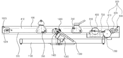
도 1은 본 발명의 제 일실시예에 따른 포복자세의 전신운동장치(체인방식)를 나타낸 평면도,1 is a plan view showing a full-body exercise device (chain method) of the crawling posture according to an embodiment of the present invention,
도 2는 도 1의 내부구성을 측면에서 바라본 도면,2 is a side view of the internal structure of FIG.
도 3은 본 발명의 제 이실시예에 따른 포복자세의 전신운동장치(와이어방식)를 나타낸 평면도,Figure 3 is a plan view showing the whole body exercise device (wire method) of the crawling posture according to the second embodiment of the present invention,
도 4는 도 3의 측면을 나타낸 도면,4 is a view showing the side of FIG.
도 5는 도 3의 와이어 교차 부분을 상세히 나타낸 도면이다.5 is a view showing in detail the wire cross section of FIG.
<도면의 주요 부분에 대한 상세한 설명><Detailed Description of Main Parts of Drawing>
100 : 메인프레임 210, 220 : 레일100:
310 : 손디딤-제1이송장치 320 : 발디딤-제1이송장치310: hand step-first transfer device 320: foot step-first transfer device
330 : 손디딤-제2이송장치 340 : 발디딤-제2이송장치330: hand step 2nd transfer device 340: foot step 2nd transfer device
350 : 고정수단 350: fixing means
410 : 체인 420 : 와이어410: chain 420: wire
500 : 구동모터 600 : 플라이휠500: drive motor 600: flywheel
610 : 제1편심공 700 : 커넥팅로드610: first eccentric 700: connecting rod
800 : 스프라킷부 810 : 제3스프라킷800: sprocket 810: third sprocket
811 : 제2편심공 820 : 제4스프라킷811: second eccentric hole 820: fourth sprocket
830 : 제5스프라킷 900 : 회전축830: fifth sprocket 900: the rotating shaft
1011 : 제1스프라킷 1012 : 회전축풀리1011: first sprocket 1012: rotating shaft pulley
1021 : 제2스프라킷 1022 : 스프라킷지지봉1021: second sprocket 1022: sprocket support rod
1023 : 지지부 1024 : 연결공1023: support 1024: connector
1025 : 볼트부 1026 : 너트부1025: bolt portion 1026: nut portion
1027 : 고정공 1027: fixing hole
1028a, 1028b, 1028c, 1028d : 방향전환풀리1028a, 1028b, 1028c, 1028d: turn pulley
1100 : 받침프레임 1200 : 중심축1100: support frame 1200: central axis
1300 : 경사조절모터 1400 : 기어부1300: inclination control motor 1400: gear unit
1500 : 이송축 1600 : 이송부재1500: feed shaft 1600: feed member
본 발명은 포복자세의 전신 운동장치에 관한 것으로서, 보다 상세하게는 포복자세에서 양손과 양발을 디딜 수 있는 디딤대가 각 레일 위에 병렬 배치되며, 상 기의 디딤대는 로울러에 의해 이송 가능토록 형성되는 것으로, 상기의 디딤대는 동력전달수단에 따른 동력 전달로 이송 가능토록 형성하되, 상기의 동력전달수단에 의한 동력 전달은 모터의 회전력에 따라 회전하는 플라이휠과, 플라이휠과 편심구조로 연결되어 왕복 직선운동을 하는 커넥팅로드와, 커넥팅로드에 의해 전달되는 동력에 의해 정회전 및 역회전을 반복하는 스프라킷부 및 회전축과, 상기 회전축의 회전력에 따라 대응하는 왕복 직선운동을 수행하는 동력전달수단의 연결구조로 이루어짐을 특징으로 한다.The present invention relates to a whole body exercise apparatus of the crawling posture, and more particularly, in the crawling posture, a stepping platform capable of supporting both hands and both feet is disposed on each rail in parallel, and the stepping board is formed to be transported by a roller. The stepping table is formed to be transported by power transmission according to the power transmission means, but the power transmission by the power transmission means is connected to the flywheel which rotates according to the rotational force of the motor, and the flywheel and the eccentric structure to reciprocate linear motion. Connecting rod, a sprocket portion for repeating the forward and reverse rotation by the power transmitted by the connecting rod and the rotating shaft, and a power transmission means for performing the corresponding reciprocating linear motion according to the rotational force of the rotating shaft. Characterized in that made.
일반적으로 요즈음 현대인들은 육체적 활동보다는 정신적 활동을 많이 하는 관계로 각종 스트레스에 의한 정신적인 질환 및 운동 부족에 의한 비만과 함께 각종 질병에 노출되거나 아니면 체력이 점차로 떨어지고 있는 실정이다.In general, modern people are more mentally active than physical activities, so they are exposed to various diseases or obesity due to mental illness caused by various stresses and lack of exercise, or physical fitness is gradually falling.
따라서, 이를 해소하기 위하여 주기적인 스포츠 활동과 함께 등산과 같은 취미활동을 보다 폭넓게 하여 체력을 보강하게 되었다.Therefore, in order to solve this problem, the sports activities such as mountain climbing and regular sports activities have been broadened to reinforce physical strength.
그러나 , 작금의 직장인들은 운동을 즐길 수 있는 공간이 극히 제한되어 있는 관계로 인하여 헬스장을 찾거나, 아니면 일반 가정에 운동기구를 구비하여 운동을 하는 경우가 대부분이다.However, most of the current office workers visit the gym because of the extremely limited space to enjoy the exercise, or the exercise equipment is usually equipped with a home at home.
일반적으로 신체를 단련하기 위한 운동기구들은, 복부, 허리, 팔, 다리 등과 같은 신체의 일부분을 단련시키고자 개발되어 왔다. 그리고 각 신체부위에 대한 단련순서에 입각하여 순차적으로 각 기구들을 사용하는 것이 통상적이다. In general, exercise devices for training the body have been developed to train a part of the body such as the abdomen, waist, arms, legs and the like. And it is common to use each apparatus sequentially based on the training procedure for each body part.
하지만 신체의 각 부분들은 서로 유기적으로 결합되어 있고, 이에 따라 어느 일부분을 단련하게 될 경우 근접 배치되는 신체의 여타 부분에도 영향을 주게 되기 때문에, 단순히 신체의 일부분을 단련시키고자 하는 목적 및 구조로 개발된 운동기However, since the parts of the body are organically bonded to each other, and thus, when one part is trained, the parts of the body affect other parts of the body that are placed in close proximity. Exerciser
구는 신체의 유기적인 구조에 기반하지 않고 개발되어 운동의 효율측면에서 큰 한계를 갖고 있는 문제점이 있다.The sphere is developed based on the organic structure of the body has a problem that has a big limitation in terms of the efficiency of exercise.
그리고 종래 신체의 일부분을 단련하고자 개발된 운동기구는, 본인의 근력으로 무게추가 연결된 레버(또는 로프 등)를 들어올리거나 잡아당기는 등의 동작이 반복되는 구조이기 때문에, 신체의 근간으로서 각 신체 일부분의 근력작용에 모두 연관되는 척추부위에 심각한 무리를 주는 경향이 있다고 알려져 있다.In addition, the exercise apparatus developed to train a part of the conventional body has a structure in which an operation of lifting or pulling a lever (or a rope, etc.) to which weight is connected by the strength of the body is repeated. It is known that there is a tendency to give a severe crowd on the spinal region which is all involved in muscle action.
이에 따라 초보자일 경우 종래 운동기구를 사용하여 무리한 운동을 시행할 경우 척추 및 각 관절 등에 신체적인 이상이 발생될 소지가 다분한 문제점을 안고 있다.Accordingly, when a beginner is unreasonable when using conventional exercise equipment, there are many problems that physical abnormalities may occur in the spine and each joint.
아울러 이러한 종래 운동기구는 대부분이 장애가 없는 신체에 맞게 개발되는 것이 일반적이기 때문에, 신체에 장애가 있을 경우에는 운동기구를 사용할 수 없으며, 사용하더라도 주위에서 보조할 수 있는 인력이 동반되어야 하는 등의 불편한 문제점이 있다.In addition, since most of these conventional exercise equipments are generally developed for a body without a disability, it is not convenient to use a sports equipment when the body has a disability, and it is inconvenient problems such as having to be accompanied by a person who can assist the surroundings even if used. There is this.
따라서 일반인의 전신운동은 물론 신체에 장애가 있더라도 보조인력의 상시적인 도움이 없이 전신운동이 가능한 구조의 운동장치 구조의 개발이 요구되고 있다.Therefore, there is a demand for the development of the structure of the exercise apparatus, which can be used for the whole body movement without the constant help of the auxiliary personnel even if the body has a physical disorder as well as the general body movement.
본 발명은 상술한 종래 기술의 문제점을 해결하기 위해 안출된 것으로서, 전기 구동모터에 의해 동작하며 양손과 양발을 이용한 전신 운동장치를 제공토록 함에 본 발명의 목적이 있다.The present invention has been made to solve the above-mentioned problems of the prior art, it is an object of the present invention to provide a whole-body exercise device using both hands and feet and operated by an electric drive motor.
또한, 본 발명은 사용자의 체력상태에 따른 강약조절 및 경사각도 생성등으로 운동 난이도를 조절할 수 있는 전신 운동장치를 제공토록 함에 본 발명의 또 다른 목적이 있다.In addition, the present invention is another object of the present invention to provide a whole-body exercise device that can adjust the exercise difficulty by adjusting the strength and intensity of inclination according to the fitness state of the user.
상기와 같은 본 발명의 목적은 바닥에 구획 설치되는 메인프레임과, 상기 메인프레임의 내측에서 메인프레임의 길이 방향을 따라 서로 병렬 배치되는 2개의 레일과, 상기 메인프레임의 내측에 구비되며 전기 에너지로 회전력을 발생시키는 구동모터와, 상기 구동모터와 연결되어 구동모터의 회전력에 따라 함께 회전운동을 하도록 구성된 플라이휠과, 상기 플라이휠의 편심 구성으로 연결되어 플라이휠의 회전운동을 직선운동으로 변환하는 커넥팅로드와, 상기 커넥팅로드의 직선운동에 따라 정회전 및 역회전을 반복할 수 있도록 구성되는 스프라킷부와, 상기 구동모터와 플라이휠과 커넥팅로드와 스프라킷부를 통하여 정회전 및 역회전 운동을 반복하는 회전축과, 상기 회전축의 종단부에 각각 연결되어 회전축의 회전력이 동력전달수단으로 전달될 수 있도록 구성된 동력연결수단과, 상기 동력연결수단을 선회하며 연장된 것으로 회전축의 회전운동에 따라 전ㆍ후 양방향으로 왕복 직선운동을 제공하는 동력전달수단과, 회전축과 대응하는 맞은편에 위치하며 동력전달수단의 진행방향을 전환하도록 형성된 방향전환부와, 상기의 레일을 따라 전ㆍ후 양방향으로 이송 가능하도록 구성된 것으로 동력전달수단의 왕복 직선운동에 대응하며 이송하도록 일측이 각각 고정수단에 의해 동력전달수단과 고정된 제1이송장치 및 제2이송장치를 포함하여 구성된 것을 특징으로 하는 포복자세의 전신 운동장치에 의해 달성된다.An object of the present invention as described above is a main frame partitioned on the floor, two rails arranged in parallel to each other in the longitudinal direction of the main frame in the inner side of the main frame, and provided in the inner side of the main frame as electrical energy A driving motor generating a rotational force, a flywheel connected to the driving motor and configured to rotate together according to the rotational force of the driving motor, and a connecting rod connected to the eccentric configuration of the flywheel to convert the rotational movement of the flywheel into a linear movement; And a sprocket portion configured to repeat forward and reverse rotation according to the linear motion of the connecting rod, and a rotating shaft for repeating the forward and reverse rotation motions through the driving motor, the flywheel, the connecting rod, and the sprocket portion. And, respectively, is connected to the end of the rotary shaft is the rotational force of the rotary shaft to be transmitted to the power transmission means And a power transmission means configured to extend the pivoting means, the power transmission means for providing a reciprocating linear motion in both the forward and backward directions according to the rotational movement of the rotary shaft, and located opposite to the rotary shaft. It is configured to be able to transfer in both directions along the rail and the direction change unit formed to switch the direction of the transmission means, one side of each power transmission by the fixing means so as to correspond to the reciprocating linear movement of the power transmission means. It is achieved by the whole body movement device of the crawling posture, characterized in that it comprises a means and a fixed first conveying device and a second conveying device.
한편, 본 발명에 있어서, 상기 동력전달수단에는 체인이 적용될 수 있으며, 동력연결수단에는 제1스프라킷이 적용될 수 있고, 방향전환부에는 제2스프라킷을 포함하여 구성되며, 상기의 체인이 제1스프라킷 및 제2스프라킷을 선회하며 연결되는 구성으로도 달성된다.On the other hand, in the present invention, the chain may be applied to the power transmission means, the first sprocket may be applied to the power connection means, the direction switching unit is configured to include a second sprocket, the chain This configuration is also achieved by pivoting the first sprocket and the second sprocket.
또한, 상기 동력전달수단에는 와이어가 적용될 수 있으며, 동력연결수단에는 회전축풀리가 적용되고, 방향전환부에는 방향전환풀리를 적용하되, 와이어의 진행방향이 서로 대각선 형태로 교차하도록 각각의 방향전환풀리가 마주보도록 소정의 각도로 기울어져 형성된 것을 특징으로 하는 포복자세의 전신 운동장치에 의해서도 달성 될 수 있다.In addition, a wire may be applied to the power transmission means, a rotation shaft pulley is applied to the power connection means, and a direction change pulley is applied to the direction change unit, and the direction change pulleys so that the traveling directions of the wires cross each other diagonally. It can also be achieved by the whole body movement device of the crawling posture, characterized in that formed to be inclined at a predetermined angle to face.
그리고 상기의 스프라킷부는, 커넥팅로드의 끝단부에 편심 구성으로 연결되어 커넥팅로드의 왕복 직선운동에 따라 정회전 및 역회전을 발생시키는 제3스프라킷과, 상기 제3스프라킷의 회전력을 전달하는 제4스프라킷과, 회전축과 연결된 것으로 상기 제4스프라킷의 회전력을 전달받아 회전축을 회전시키는 제5스프라킷을 포함하여 구성하고 상기 각각의 회전력의 매개체는 체인인 것이 특징이다.And the sprocket portion is connected to the end of the connecting rod in an eccentric configuration, the third sprocket for generating the forward and reverse rotation in accordance with the reciprocating linear motion of the connecting rod and the rotational force of the third sprocket It comprises a fourth sprocket for transmitting a; and a fifth sprocket for rotating the rotary shaft by receiving the rotational force of the fourth sprocket connected to the rotating shaft and the medium of the respective rotational force is a chain to be.
또한, 플라이휠 또는 제3스프라킷에는 중심으로부터 이격된 서로 다른 위치에 다수의 편심공을 형성하여 편심 회전운동의 크기를 조절할 수 있음이 특징이다.In addition, the flywheel or the third sprocket is characterized in that the size of the eccentric rotation can be adjusted by forming a plurality of eccentric holes at different positions spaced from the center.
또한, 상기의 커넥팅로드의 외주연에는 수나사를 형성하며, 플라이휠 및 기어부에서 커넥팅로드가 연결되는 부위에는 커넥팅로드가 결합되어 관통하도록 암나사를 형성함으로써 플라이휠 및 스프라킷부 사이에 연결된 커넥팅로드의 길이를 조절할 수 있음이 특징이다.In addition, the outer circumference of the connecting rod is formed with a male thread, and the connecting rod is coupled to the connecting rod in the portion connected to the connecting rod in the flywheel and gear portion by forming a female screw to penetrate the length of the connecting rod connected between the flywheel and the sprocket portion The feature is that it can be adjusted.
아울러, 상기 방향전환부는, 좌·우 양측에 각각 형성되어 체인이 선회할 수 있도록 구성된 제2스프라킷과, 상기의 양측에 각각 구성된 제2스프라킷을 연결하여 지지하는 스프라킷지지봉과, 전방측 메인프레임에 있어서, 내측으로 부분 돌출된 지지부와, 상기 지지부의 내측에서 스프라킷지지봉이 관통하며 연결되도록 형성된 것으로, 체인의 길이 조절이 가능하도록 메인프레임의 전방측을 향해 길게 형성되는 연결공과, 상기의 스프라킷지지봉이 지지부에 고정될 수 있도록 스프라킷지지봉으로부터 돌출된 볼트부 및 볼트부와 결합되는 너트부와, 상기의 지지부측 프레임에 스프라킷지지봉의 볼트부가 관통하여 고정될 수 있도록 형성된 고정공을 포함하여 구성되는 것이 바람직하다.In addition, the direction switching unit, the sprocket support rods are formed on each of the left and right sides and configured to allow the chain to rotate, and the sprocket support rods connecting and supporting the second sprockets respectively configured on both sides; In the front main frame, the support part partially protruded inward, and the sprocket support rod penetrates and is connected to the inside of the support part, and is formed to be long toward the front side of the main frame to adjust the length of the chain. A connecting hole, a nut part engaged with the bolt portion and the bolt portion protruding from the sprocket support rod so that the sprocket support rod can be fixed to the support portion, and the bolt portion of the sprocket support rod penetrates the frame of the support portion side. It is preferably configured to include a fixing hole formed to be fixed.
또한, 동력전달수단은 동력연결수단 및 방향전환부를 선회하며 상하로 이격된 두 줄로 양측에 각각 형성되며, 제1이송장치 및 제2이송장치는 상하로 이격된 동력전달수단의 선택적 위치에 각각 고정되며, 상기의 제1이송장치 및 제2이송장치가 동력전달수단에 고정되는 위치는 변경 가능하며, 제1이송장치 및 제2이송장치가 동력전달수단에 고정되는 위치에 따라 다양한 동작의 운동형태를 사용자에게 제공하는 것이 바람직하다.In addition, the power transmission means is formed on both sides by turning the power connecting means and the direction switching unit in two rows spaced up and down, respectively, the first transfer device and the second transfer device is fixed in the selective position of the power transmission means spaced up and down respectively The position at which the first transfer device and the second transfer device are fixed to the power transmission means can be changed, and the movement form of the various operations depends on the position at which the first transfer device and the second transfer device are fixed to the power transmission means. It is desirable to provide a to the user.
그리고 메인프레임의 하단에 구성되는 받침프레임과, 상기 받침프레임과 메 인프레임의 소정 부위가 중첩된 상태에서 회동 가능하도록 연결된 중심축과, 받침프레임과 메인프레임간의 경사각을 생성시 구동되며 받침프레임측에 고정되는 경사조절모터와, 상기 경사조절모터와 연결되어 회전하는 기어부와, 메인프레임의 중심 하단부에 회동 가능토록 연결되며 외주연에는 수나사가 형성된 소정의 길이를 갖는 이송축과, 상기 이송축과 결합되어 수나사의 형성 방향을 따라 이송동작을 행하도록 내측에는 암나사를 형성한 것으로 기어부의 회전력을 전달받도록 구성되며, 또한 몸통은 받침프레임에 지지되도록 고정된 이송부재를 더 포함하여 구성하여 운동장치의 경사각을 조절할 수 있도록 하는 것이 바람직하다.And the support frame is formed at the bottom of the main frame, the center axis connected so as to rotate in a state where the predetermined portion of the support frame and the main frame overlaps, and is driven when generating the inclination angle between the support frame and the main frame, A fixed shaft adjusting motor, a gear unit which is connected to the tilt adjusting motor and rotated, a feed shaft connected to the center lower end of the main frame so as to be rotatable, and having a predetermined length having an external thread formed on an outer circumference thereof; Coupled to form a female screw on the inside to perform the transfer operation along the forming direction of the male screw is configured to receive the rotational force of the gear portion, and the body further comprises a transfer member fixed to be supported by the support frame to the It is desirable to be able to adjust the inclination angle.
본 발명은 포복자세로 운동이 가능한 전신 운동장치에 관한 것으로서, 사용자가 포복자세에서 양손 및 양발을 다양한 형태로 이격시키고 모아주는 모습의 운동형태를 반복적으로 구현함으로 사용자는 전신운동의 효과를 얻을 수 있도록 제안된 전신 운동장치에 관한 것이다. The present invention relates to a whole body exercise apparatus capable of exercising in a crawling posture, and the user repeatedly realizes a form of movement in which the user separates and collects both hands and feet in various forms in the crawling posture, so that the user can obtain the effect of the whole body workout. The whole body exercise apparatus proposed to be.
이하, 첨부된 도면을 참조하면서 본 발명에 대해 상세하게 설명한다.Hereinafter, the present invention will be described in detail with reference to the accompanying drawings.
본 발명의 실시예에 따른 포복자세의 전신운동장치는, 직사각 형태로 바닥에 구획 설치되는 메인프레임(100)과, 상기 메인프레임(100)의 내측에서 메인프레임(100)의 길이 방향을 따라 서로 병렬 배치되는 2개의 레일(210,220)과, 상기의 레일(210,220)을 따라 전ㆍ후 방향으로 이송이 가능하도록 구성된 제1이송장 치(310,320) 및 제2이송장치(330,340)와, 상기 제1,2이송장치(310,320,330,340)의 이송운동을 제어하는 것으로 제1,2이송장치(310,320,330,340)와 고정수단(350)에 의해 고정되며 회전축(900)으로부터 전달되는 부분 회전운동에 따라 전ㆍ후 방향으로 직선 왕복 직선운동을하는 동력전달수단을 포함하여 구성된다.The whole body movement apparatus of the crawling posture according to the embodiment of the present invention, the
또한, 상기의 동력전달수단에 왕복 직선운동을 전달하기 위한 구성으로는, 전기 에너지로 회전력을 발생시키는 구동모터(500)와, 상기 구동모터(500)와 연결되어 구동모터(500)의 회전력에 따라 함께 회전운동을 하도록 구성된 플라이휠(600)과, 상기 플라이휠(600)의 편심 구성으로 연결되어 플라이휠(600)의 회전운동을 직선운동으로 변환하는 커넥팅로드(700)와, 상기 커넥팅로드(700)의 직선운동에 따라 정회전 및 역회전을 반복할 수 있도록 구성된 스프라킷부(800)와, 상기 스프라킷부(800)의 회전운동에 따라 함께 대응하며 정회전 및 역회전 운동을 반복하는 회전축(900)과, 상기 회전축(900)의 양측 종단부에 각각 연결되어 회전축(900)의 회전력이 동력전달수단으로 전달될 수 있도록 구성된 동력연결수단과, 메인프레임(100)의 전방 내측에 위치하여 동력전달수단의 진행방향을 전환하도록 구성된 방향전환부를 포함하여 구성된다.In addition, the configuration for transmitting the reciprocating linear motion to the power transmission means, the
본 발명의 실시예에 따른 동작 과정과 함께 본 발명의 구성을 보다 상세하게 설명한다.The configuration of the present invention together with the operation process according to an embodiment of the present invention will be described in more detail.
전기 에너지를 인가받은 구동모터(500)는 회전력을 발생시키며, 구동모터(500)의 회전력은 플라이휠(600)로 전달된다. 상기에서 플라이휠(600)은 중심으 로부터 이격된 다수의 제1편심공(610)을 형성하고 있으며, 상기의 제1편심공(610)에는 커넥팅로드(700)가 연결되어 플라이휠(600)의 회전운동이 커넥팅로드(700)의 직선운동으로 변환된다. 바람직하게, 상기의 제1편심공(610)은 플라이휠(600)의 중심으로부터 이격된 서로 다른 위치에 다수개를 형성함으로써 커넥팅로드(700)가 연결되는 위치를 조절할 수 있도록 한다. 상기의 제1편심공(610)에 있어서 중심부에서 멀어진 위치일수록 편심 회전운동이 커지며 그에 따라 커넥팅로드(700)의 직선 운동거리도 달라지게 된다. The driving
일측이 플라이휠(600)의 제1편심공(610)에 연결된 커넥팅로드(700)의 또 다른 일측은 스프라킷부(800)로 연결된다. 스프라킷부(800)는 다수의 스프라킷이 서로 맞물려 체인으로 동작되는 구성으로 커넥팅로드(700)와 연결되는 제3스프라킷(810)과, 상기 제3스프라킷(810)의 회전력을 전달하는 제4스프라킷(820)과, 회전축(900)과 연결된 것으로 상기 제4스프라킷(820)의 회전력을 전달받아 회전축(900)을 회전시키는 제5스프라킷(830)을 포함하여 구성된다. 상기에서 커넥팅로드(700)와 연결되는 제3스프라킷(810)의 중심에서 이격된 위치에는 제2편심공(811)을 형성하여 커넥팅로드(700)가 연결되도록 구성되며 커넥팅로드(700)의 직선운동에 따라 제3스프라킷(810)은 정방향 및 역방향으로 각각 일부분씩 부분 회전운동을 하도록 구성된다. 바람직하게, 상기의 제2편심공(811)은 제3스프라킷(810)의 중심으로부터 이격된 서로 다른 위치에 다수개를 형성함으로써 커넥팅로드(700)가 연결되는 위치를 조절할 수 있으며, 그에 따른 편심 회전운동의 크기도 조절할 수 있음을 특징으로 한다.Another side of the connecting
제3스프라킷(810)의 부분 회전운동은 제4스프라킷(820)을 통해 회전축(900)과 연결된 제5스프라킷(830)으로 전달되며, 이때 제5스프라킷(830)은 다른 스프라킷(810,820)에 비해 상대적으로 직경이 작은 스프라킷을 적용하여 회전축(900)이 회전하는 횟수를 증가시켰다.Partial rotational movement of the
상기에서 커넥팅로드(700) 외주연에는 수나사를 형성하며 플라이휠(600) 및 제3스프라킷(810)에서 커넥팅로드(700)가 연결되는 부위에는 암나사를 형성함으로써 플라이휠(600) 및 제3스프라킷(810) 사이를 연결하고 있는 커넥팅로드(700)의 길이 조절이 가능토록 할 수 있다. In the above, the outer circumference of the connecting
즉, 본 발명의 실시예에 따른 전신 운동장치의 난이도는 커넥팅로드(700)의 직선 운동거리에 따라서도 작용된다. 여기서 커넥팅로드(700)의 직선 운동거리에 영향을 미치는 요소는 커넥팅로드(700)의 길이 또는 편심 회전운동의 크기에 따라서 달라지며, 본 발명의 실시예에 따르면 커넥팅로드(700)의 길이조절 뿐 아니라 플라이휠(600) 및 제3스프라킷(810)에 형성된 다수의 제1,2편심공(610,811)에 따라 편심 회전운동의 크기에 변화를 주어 전신 운동장치의 난이도 조절을 가능토록 하였다.That is, the difficulty of the whole body exercising apparatus according to the embodiment of the present invention also acts according to the linear movement distance of the connecting
회전축(900)의 양측 종단부에는 각각의 동력연결수단이 연결되며, 동력전달수단은 상기의 동력연결수단을 선회하며 연장되도록 구성된다. 즉, 회전축(900)의 정방향 및 역방향에 따른 회전운동을 동력전달수단을 밀고 당기는 왕복 직선운동으로 작용하도록 구성된다.Each of the power connecting means is connected to both ends of the
본 발명의 실시예에 따른 동력전달수단은 체인(410) 또는 와이어(420)를 이용한 형태로 구분할 수 있다.Power transmission means according to an embodiment of the present invention can be divided into a form using a
이하, 본 발명의 제 일실시예에 따라 동력전달수단으로 체인(410)을 적용한 전신 운동장치의 구성 및 동작방법에 대해 상세하게 설명한다.Hereinafter, the configuration and operation method of the whole body exercise apparatus to which the
동력전달수단으로 적용되는 체인(410)은 연결된 일체형으로 메인프레임(100)의 내측 길이방향에 해당하는 양측부위에 각각 연결된다. 이때, 체인(410)의 일측은 제1스프라킷(1011)과 연결되며 또 다른 일측은 대응하는 맞은편 제2스프라킷(1021)과 연결된다.The
즉, 동력전달수단으로 체인(410)을 적용하게 되면 회전축(900)의 양측 종단부에 연결하는 동력연결수단으로는 체인(410)과 연결되기 위한 제1스프라킷(1011)이 적용된다. 또한, 대응하는 맞은편에는 제2스프라킷(1021)을 형성하되 제1스프라킷(1011)과 대응하도록 양측에 각각 형성된다.That is, when the
상기에서 양측에 각각 형성된 제2스프라킷(1021)은 스프라킷지지봉(1022)에 의해 연결 및 지지되며, 상기의 스프라킷지지봉(1022)은 메인프레임(100)의 내측으로 부분 돌출된 지지부(1023)에 의해 지지된다. The
상기의 지지부(1023)는 내측에 스프라킷지지봉(1022)이 관통하며 연결되도록 연결공(1024)을 형성하되, 상기의 연결공(1024)은 메인프레임(100)의 전방측을 향해 길게 형성되어 있다. 이는 체인(410)의 장기간 사용으로 인해 그 길이가 인장되었을시 제2스프라킷(1021)이 연결된 스프라킷지지봉(1022)을 메인프레임(100)의 전방측으로 이동하여 느슨해진 체인(410)을 팽팽히 보완할 수 있도록 구성된 것이다. 이때, 스프라킷지지봉(1022)이 지지부(1023)에 고정되기 위해서는 스프라킷지지봉(1022)의 일측으로부터 돌출된 볼트부(1025) 및 볼트부(1025)와 체결되는 너트부(1026)를 형성하며, 지지부(1023)측 프레임에 볼트부(1025)가 관통하여 고정될 수 있도록 형성된 고정공(1027)을 포함하여 구성된다.The
이하, 본 발명의 제 이실시예에 따라 동력전달수단으로 와이어(420)를 적용한 전신 운동장치의 구성 및 동작방법에 대해 상세하게 설명한다.Hereinafter, the configuration and operation method of the whole body exercise apparatus to which the
와이어(420)는 종단부가 없이 좌ㆍ우 양측이 모두 일체로 연결된 구성을 갖으며, 회전축(900)의 양측 종단부에 연결되는 동력연결수단으로는 회전축풀리(1012)가 적용된다.The
회전축풀리(1012)를 각각 선회하며 연장된 와이어(420)는 메인프레임(100)의 전방측에 형성된 방향전환풀리(1028a, 1028b, 1028c, 1028d)에 의해 와이어(420)의 진행 방향이 서로 교차하도록 이루어진다. 즉, 방향전환풀리(1028a, 1028b, 1028c, 1028d)는 와이어(420)의 진행 방향이 'X'자 형태로 교차하도록 각각 대각선 방향으로 마주보도록 소정의 각도만큼 기울어진 형태로 이루어진다. The
즉, 우측 회전축풀리(1012)를 상향으로 선회한 와이어(420)는 메인프레임(100)의 전방측을 향해 우측 상향으로 연장될 것이며, 와이어(420)는 방향전환풀리(1028a, 1028b)를 선회하며 좌측 하향으로 방향전환을 할 것이다. 또한, 좌측 회전축풀리(1012)를 상향으로 선회한 와이어(420)는 메인프레임(100)의 전방측을 향해 좌측 상향으로 연장될 것이며, 와이어(420)는 방향전환풀리(1028c, 1028d)를 선 회하며 우측 하향으로 방향전환을 할 것이다.That is, the
상기와 같은 와이어(420)에 의한 전신 운동장치의 구성은 회전축풀리(1010)를 중심으로 상ㆍ하로 이격된 와이어(420)에 있어서, 양측 상향에 위치한 와이어(420)와 양측 하향에 위치한 와이어(420)의 진행 방향을 동일하다는 특징이 있다.The structure of the whole-body exercise apparatus by the
메인프레임(100)의 내측에는 메인프레임(100)의 길이 방향으로 각각 병렬 배치되는 2개의 레일(210,220)이 형성되어 있으며, 상기의 레일(210,220)을 따라 전ㆍ후 방향으로 이송이 가능하도록 구성된 제1이송장치(310,320) 및 제2이송장치(330,340)가 형성된다. Inside the
제1이송장치(310,320) 및 제2이송장치(330,340)는 레일(210,220)을 따라 이송될 수 있도록 로울러가 포함된 구성을 갖으며, 제1이송장치(310,320)는 손디딤-제1이송장치(310)와 발디딤-제1이송장치(320)로 구분되며, 또한 제2이송장치(330,340)에 있어서도 손디딤-제2이송장치(330)와 발디딤-제2이송장치(340)로 구분된다.The first conveying apparatus (310,320) and the second conveying apparatus (330,340) has a configuration including a roller to be transported along the rails (210, 220), the first conveying device (310,320) is a hand tread-first conveying device It is divided into 310 and the stepping-
상기에서 제1이송장치(310,320) 및 제2이송장치(330,340)는 동력전달수단의 직선방향 이동 동작에 대응하도록 고정수단(350)을 이용하여 동력전달수단과 연결된 구성을 갖는다. The first transfer device (310,320) and the second transfer device (330,340) has a configuration connected to the power transmission means using the fixing means 350 to correspond to the linear movement of the power transmission means.
동력전달수단은 회전축풀리(1010)를 선회하며 상하로 이격된 두 줄로 양측에 각각 형성되며, 상하로 이격된 동력전달수단 중 어느 하나의 선택된 위치에 각각 제1이송장치(310,320) 및 제2이송장치(330,340)가 고정된다.The power transmission means is formed on both sides of the two rows spaced up and down while rotating the
상기에서, 제1이송장치(310,320) 및 제2이송장치(330,340)는 양측에서 각각 상하로 이격된 동력전달수단의 어느 한 라인에 각각 연결 고정되며, 제1이송장치(310,320) 및 제2이송장치(330,340)와 고정되는 동력전달수단의 라인 위치에 따라 다양한 동작의 운동형태를 사용자에게 제공할 수 있는 것이다. 또한, 사용자에 의해 동력전달수단의 각각 라인과 고정되는 제1이송장치(310,320) 및 제2이송장치(330,340)의 위치변경이 가능함을 제공한다.In the above, the first transfer device (310,320) and the second transfer device (330,340) are respectively fixed to any one line of the power transmission means spaced up and down respectively on both sides, the first transfer device (310,320) and the second transfer According to the position of the line of the power transmission means fixed to the device (330, 340) it can provide the user with various types of movement. In addition, it is possible to change the position of the first transfer device (310,320) and the second transfer device (330,340) fixed to each line of the power transmission means by the user.
예로, 본 발명의 제 이실시예에 따른 와이어(420)를 제공한 구성에 있어서, 본 발명의 제1이송장치(310,320) 및 제2이송장치(330,340)와의 연결과 그에 따른 동작 과정을 설명한다.For example, in the configuration in which the
손디딤-제1이송장치(310)와 발디딤-제1이송장치(320)는 상하로 이격된 와이어(420) 중 어느 하나의 위치에 각각 고정된다. 또한, 제2이송장치(330,340)의 와이어(420)와의 연결은 제1이송장치(310,320)의 와이어(420) 연결에 상하 반대로 대응하도록 연결된다. 즉, 손디딤-제1이송장치(310)의 상ㆍ하 와이어(420)고정과 반대로 대응하도록 와이어(420)와 손디딤-제2이송장치(330)의 고정이 이루어지며, 또한 발디딤-제1이송장치(320)의 상ㆍ하 와이어(420)고정과 반대로 대응하도록 와이어(420)와 발디딤-제2이송장치(340)의 고정이 이루어진다.The hand tread-
예를들어, 우측 하부방향 와이어(420)에 손디딤-제1이송장치(310)가 고정되면 좌측 상부방향에 손디딤-제2이송장치(330)가 고정되며, 우측 상부방향 와이 어(420)에 발디딤-제1이송장치(320)가 고정되면 좌측 하부방향에 발디딤-제2이송장치(340)가 고정되는 것이다.For example, when the hand tread-
상기와 같은 제1이송장치(310,320) 및 제2이송장치(330,340)와 와이어(420)의 고정방향에 의하면, 사용자의 오른손과 오른발이 만나는 동작시 왼손과 왼발은 이격된 형태를 이룰것이며, 왼손과 왼발이 만나는 동작에서는 오른손과 오른발이 이격된 형태를 이룰것이다. 본 발명의 실시예에 따르면 이러한 동작이 반복되는 과정을 통해 사용자는 전신 운동 효과를 누릴 수 있는 것이다.According to the fixed direction of the first transfer device (310,320) and the second transfer device (330,340) and the
본 발명의 실시예에 따른 전신 운동장치는 운동 효과를 높이기 위하여 경사각을 조절할 수 있으며 그에 따른 구성은 다음과 같다.The whole-body exercise apparatus according to the embodiment of the present invention can adjust the inclination angle to increase the exercise effect, and the configuration thereof is as follows.
메인프레임(100)의 하단에 위치한 받침프레임(1100)과, 상기 받침프레임(1100)과 메인프레임(100)의 소정 부위가 중첩된 상태에서 회동 가능하도록 연결된 것으로 메인프레임(100)의 경사조절시 중심이 되는 중심축(1200)과, 받침프레임(1100)과 메인프레임(100)간의 경사각을 생성시 구동되는 경사조절모터(1300)와, 상기 경사조절모터(1300)와 연결되어 회전하는 다수의 기어로 구성된 기어부(1400)와, 메인프레임(100)의 중심 하단부에 회동 가능토록 연결되며 외주연에는 수나사가 형성된 소정의 길이를 갖는 이송축(1500)과, 상기 이송축(1500)과 결합되어 수나사의 형성 방향을 따라 이송동작을 행하도록 내측에는 암나사를 형성한 것으로 기어부(1400)의 회전력을 전달받도록 구성되며, 또한 몸통은 받침프레임(1100)에 지지되도록 고정된 이송부재(1600)를 포함하여 구성된다.When the inclination of the
이상에서 본 발명에 대한 기술 사상을 첨부 도면과 함께 서술하였지만 이는 본 발명의 가장 양호한 실시 예를 예시적으로 설명한 것이지 본 발명을 한정하는 것은 아니다. 또한, 이 기술 분야의 통상의 지식을 가진 자이면 누구나 본 발명의 기술 사상의 범주를 이탈하지 않는 범위 내에서 다양한 변형 및 모방이 가능함은 명백한 사실이다.The technical spirit of the present invention has been described above with reference to the accompanying drawings, but this is by way of example only and not by way of limitation. In addition, it is obvious that any person skilled in the art may make various modifications and imitations without departing from the scope of the technical idea of the present invention.
상술한 바와 같이 본 발명에 의한 포복자세의 전신 운동장치에 의하면 다음과 같은 효과가 있다.As described above, the whole body exercise apparatus of the crawling posture according to the present invention has the following effects.
첫째, 포복자세로 양손 및 양발을 이송시키는 구조에 의해서 전신 스트레칭을 반복할 수 있는 전신 운동의 효과가 있다.First, there is an effect of the whole body movement that can be repeated throughout the body by the structure that transports both hands and feet in a crawl position.
둘째, 운동장치는 구동모터에 의한 구동력 제공수단이 구비되기 때문에 신체에 장애가 있는 사람도 쉽게 전신운동을 할 수 있는 효과도 있다.Second, since the exercise device is provided with a driving force providing means by the drive motor, there is an effect that even a person with a physical disability can easily exercise the whole body.
셋째, 커넥팅로드의 길이조절 및 플라이휠과 제3스프라킷에 형성된 편심공의 위치 변경을 통해 편심 회전운동의 크기를 변경할 수 있으며 그에 따른 운동량을 조절할 수 있는 효과도 있다.Third, the size of the eccentric rotation can be changed by adjusting the length of the connecting rod and changing the position of the eccentric hole formed in the flywheel and the third sprocket, and the amount of exercise can be adjusted accordingly.
넷째, 전방이 들어 올려지는 구조로 경사각을 형성할 수 있어 운동력을 증가할 수 있는 효과도 있다.Fourth, it is possible to form an inclination angle to the front lifting structure there is an effect that can increase the exercise force.
Claims (9)
Priority Applications (1)
| Application Number | Priority Date | Filing Date | Title |
|---|---|---|---|
| KR1020070044070A KR100868982B1 (en) | 2007-05-07 | 2007-05-07 | Creature Posture |
Applications Claiming Priority (1)
| Application Number | Priority Date | Filing Date | Title |
|---|---|---|---|
| KR1020070044070A KR100868982B1 (en) | 2007-05-07 | 2007-05-07 | Creature Posture |
Publications (2)
| Publication Number | Publication Date |
|---|---|
| KR20080098783A true KR20080098783A (en) | 2008-11-12 |
| KR100868982B1 KR100868982B1 (en) | 2008-11-17 |
Family
ID=40286019
Family Applications (1)
| Application Number | Title | Priority Date | Filing Date |
|---|---|---|---|
| KR1020070044070A Expired - Fee Related KR100868982B1 (en) | 2007-05-07 | 2007-05-07 | Creature Posture |
Country Status (1)
| Country | Link |
|---|---|
| KR (1) | KR100868982B1 (en) |
Cited By (1)
| Publication number | Priority date | Publication date | Assignee | Title |
|---|---|---|---|---|
| CN106964167A (en) * | 2017-04-17 | 2017-07-21 | 四川城市职业学院 | A kind of early education sports equipment sunlight tunnel |
Families Citing this family (1)
| Publication number | Priority date | Publication date | Assignee | Title |
|---|---|---|---|---|
| KR102271943B1 (en) | 2019-11-12 | 2021-07-02 | 백범준 | Prefabricated body exercise device |
Family Cites Families (3)
| Publication number | Priority date | Publication date | Assignee | Title |
|---|---|---|---|---|
| US5407406A (en) | 1993-06-16 | 1995-04-18 | Canela; Heriberto | Exercise device for handicapped children |
| KR20050018446A (en) * | 2003-08-13 | 2005-02-23 | 박봉수 | Abdominal exercise machine having rail structure on which user lies and moves arms and legs like tiger walking |
| KR100538203B1 (en) * | 2003-11-26 | 2005-12-22 | 백범준 | A Whole Body Exercise Device Of Creeping Posture |
-
2007
- 2007-05-07 KR KR1020070044070A patent/KR100868982B1/en not_active Expired - Fee Related
Cited By (1)
| Publication number | Priority date | Publication date | Assignee | Title |
|---|---|---|---|---|
| CN106964167A (en) * | 2017-04-17 | 2017-07-21 | 四川城市职业学院 | A kind of early education sports equipment sunlight tunnel |
Also Published As
| Publication number | Publication date |
|---|---|
| KR100868982B1 (en) | 2008-11-17 |
Similar Documents
| Publication | Publication Date | Title |
|---|---|---|
| CN101516315B (en) | passive movement aids | |
| US10653914B2 (en) | Upper and lower body push and pull exercise machine with a one directional resistance mechanism and adjustable angle | |
| US11524206B2 (en) | Upper and lower body push and pull exercise machine with a one directional resistance mechanism and adjustable angle | |
| KR101661465B1 (en) | Apparatus of upper and lower for gait training | |
| KR100868983B1 (en) | Creature Posture | |
| US20250135262A1 (en) | Load transmission mechanism unit for training machine and training machine employing same | |
| JP5806120B2 (en) | Exercise assistance device | |
| CN104826270A (en) | Multidirectional intelligent tendon stretching device | |
| KR100717815B1 (en) | Creature Posture | |
| KR101180093B1 (en) | Green massage apparatus using power from cycle | |
| KR100868982B1 (en) | Creature Posture | |
| KR101093558B1 (en) | Full body exercise equipment | |
| KR102184611B1 (en) | Cross type exercise apparatus for rehabilitating upper limb and leg | |
| US11116688B2 (en) | Apparatus for improving exercise equipment and a method of using the same | |
| KR20030036427A (en) | Health machine using pedals | |
| US9772015B2 (en) | Linear powered input device | |
| KR100723297B1 (en) | Manual telegraph | |
| KR100392525B1 (en) | Excercising apparatus for enhancing oxygen supply to the upper body | |
| CN212466986U (en) | Easy dismounting's body-building training apparatus | |
| CN110585654B (en) | A device for exercising hands and feet of patients | |
| KR20100109185A (en) | Fitness equipment | |
| KR101045433B1 (en) | The whole body sporting goods | |
| KR20200117469A (en) | Step fitness equipment | |
| KR200319057Y1 (en) | Health machine using pedals | |
| KR100804315B1 (en) | Whole body exercise equipment |
Legal Events
| Date | Code | Title | Description |
|---|---|---|---|
| A201 | Request for examination | ||
| PA0109 | Patent application |
St.27 status event code: A-0-1-A10-A12-nap-PA0109 |
|
| PA0201 | Request for examination |
St.27 status event code: A-1-2-D10-D11-exm-PA0201 |
|
| D13-X000 | Search requested |
St.27 status event code: A-1-2-D10-D13-srh-X000 |
|
| D14-X000 | Search report completed |
St.27 status event code: A-1-2-D10-D14-srh-X000 |
|
| E902 | Notification of reason for refusal | ||
| PE0902 | Notice of grounds for rejection |
St.27 status event code: A-1-2-D10-D21-exm-PE0902 |
|
| P11-X000 | Amendment of application requested |
St.27 status event code: A-2-2-P10-P11-nap-X000 |
|
| P13-X000 | Application amended |
St.27 status event code: A-2-2-P10-P13-nap-X000 |
|
| E701 | Decision to grant or registration of patent right | ||
| PE0701 | Decision of registration |
St.27 status event code: A-1-2-D10-D22-exm-PE0701 |
|
| GRNT | Written decision to grant | ||
| PR0701 | Registration of establishment |
St.27 status event code: A-2-4-F10-F11-exm-PR0701 |
|
| PR1002 | Payment of registration fee |
St.27 status event code: A-2-2-U10-U11-oth-PR1002 Fee payment year number: 1 |
|
| PG1501 | Laying open of application |
St.27 status event code: A-1-1-Q10-Q12-nap-PG1501 |
|
| PG1601 | Publication of registration |
St.27 status event code: A-4-4-Q10-Q13-nap-PG1601 |
|
| FPAY | Annual fee payment |
Payment date: 20110928 Year of fee payment: 4 |
|
| PR1001 | Payment of annual fee |
St.27 status event code: A-4-4-U10-U11-oth-PR1001 Fee payment year number: 4 |
|
| FPAY | Annual fee payment |
Payment date: 20121023 Year of fee payment: 5 |
|
| PR1001 | Payment of annual fee |
St.27 status event code: A-4-4-U10-U11-oth-PR1001 Fee payment year number: 5 |
|
| LAPS | Lapse due to unpaid annual fee | ||
| PC1903 | Unpaid annual fee |
St.27 status event code: A-4-4-U10-U13-oth-PC1903 Not in force date: 20131111 Payment event data comment text: Termination Category : DEFAULT_OF_REGISTRATION_FEE |
|
| PC1903 | Unpaid annual fee |
St.27 status event code: N-4-6-H10-H13-oth-PC1903 Ip right cessation event data comment text: Termination Category : DEFAULT_OF_REGISTRATION_FEE Not in force date: 20131111 |
|
| P22-X000 | Classification modified |
St.27 status event code: A-4-4-P10-P22-nap-X000 |