KR20080098191A - Motor system and method including relay - Google Patents
Motor system and method including relay Download PDFInfo
- Publication number
- KR20080098191A KR20080098191A KR1020070043551A KR20070043551A KR20080098191A KR 20080098191 A KR20080098191 A KR 20080098191A KR 1020070043551 A KR1020070043551 A KR 1020070043551A KR 20070043551 A KR20070043551 A KR 20070043551A KR 20080098191 A KR20080098191 A KR 20080098191A
- Authority
- KR
- South Korea
- Prior art keywords
- motor
- relay
- unit
- cpu
- relay unit
- Prior art date
- Legal status (The legal status is an assumption and is not a legal conclusion. Google has not performed a legal analysis and makes no representation as to the accuracy of the status listed.)
- Ceased
Links
- 238000000034 method Methods 0.000 title claims abstract description 11
- XLYOFNOQVPJJNP-UHFFFAOYSA-N water Substances O XLYOFNOQVPJJNP-UHFFFAOYSA-N 0.000 claims abstract description 30
- 238000012360 testing method Methods 0.000 claims abstract description 26
- 230000005611 electricity Effects 0.000 claims abstract description 17
- 238000004088 simulation Methods 0.000 claims description 3
- 238000007689 inspection Methods 0.000 claims description 2
- 238000009434 installation Methods 0.000 abstract description 5
- 230000006870 function Effects 0.000 description 5
- 238000010586 diagram Methods 0.000 description 4
- 230000000694 effects Effects 0.000 description 1
- 230000007257 malfunction Effects 0.000 description 1
- 238000012986 modification Methods 0.000 description 1
- 230000004048 modification Effects 0.000 description 1
- 230000035945 sensitivity Effects 0.000 description 1
- 239000002699 waste material Substances 0.000 description 1
Images


Classifications
-
- H—ELECTRICITY
- H02—GENERATION; CONVERSION OR DISTRIBUTION OF ELECTRIC POWER
- H02H—EMERGENCY PROTECTIVE CIRCUIT ARRANGEMENTS
- H02H3/00—Emergency protective circuit arrangements for automatic disconnection directly responsive to an undesired change from normal electric working condition with or without subsequent reconnection ; integrated protection
- H02H3/006—Calibration or setting of parameters
-
- H—ELECTRICITY
- H02—GENERATION; CONVERSION OR DISTRIBUTION OF ELECTRIC POWER
- H02H—EMERGENCY PROTECTIVE CIRCUIT ARRANGEMENTS
- H02H3/00—Emergency protective circuit arrangements for automatic disconnection directly responsive to an undesired change from normal electric working condition with or without subsequent reconnection ; integrated protection
- H02H3/02—Details
- H02H3/04—Details with warning or supervision in addition to disconnection, e.g. for indicating that protective apparatus has functioned
-
- H—ELECTRICITY
- H02—GENERATION; CONVERSION OR DISTRIBUTION OF ELECTRIC POWER
- H02H—EMERGENCY PROTECTIVE CIRCUIT ARRANGEMENTS
- H02H7/00—Emergency protective circuit arrangements specially adapted for specific types of electric machines or apparatus or for sectionalised protection of cable or line systems, and effecting automatic switching in the event of an undesired change from normal working conditions
- H02H7/08—Emergency protective circuit arrangements specially adapted for specific types of electric machines or apparatus or for sectionalised protection of cable or line systems, and effecting automatic switching in the event of an undesired change from normal working conditions for dynamo-electric motors
- H02H7/0822—Integrated protection, motor control centres
Landscapes
- Tests Of Circuit Breakers, Generators, And Electric Motors (AREA)
- Control Of Electric Motors In General (AREA)
Abstract
본 발명은 모터 제어를 위한 각종 버튼 및 모터 보호 계전기, 검사기, 콘트롤러 등이 기능을 일체화한 종합 디지털 모터 보호 제어 장치로서 계전기가 시스템에 일체화되어 있어 다양한 씨퀀스에 적용가능하며 자체 테스트 실시, CT실시, 수위조정이 사용자의 설정에 의해 자유롭게 설정/실시 할 수 있으며 설치 전선이 많이 들지않아 전력소모가 절감되며 계전기가 디지털 전자화 되어 있어 정확한 릴레이 동작과 정밀한 디지털 데이터를 얻어 낼 수 있고 전자 센서를 설치하고 있어 정확하고 오차없는 센싱이 가능한 계전기를 포함한 모터 시스템 및 방법에 관한 것이다.The present invention is a comprehensive digital motor protection control device in which various buttons and motor protection relays, testers, controllers, etc. for motor control are integrated, and the relay is integrated in the system, and can be applied to various sequences. The level adjustment can be freely set / executed by the user's setting, and the power consumption is reduced because there is not much installation wire, and the relay is digitalized to obtain accurate relay operation and precise digital data, and the electronic sensor is installed. A motor system and method including a relay capable of accurate and error-free sensing.
본 발명은 모터 제어 시스템에 있어서, 3상전원을 받아 상기 모터(6)를 보호하며 전자식으로 동작하고 계전부(3); 보조회로(1)로 전기를 공급하는 전자식 모터 보호용 릴레이부(2); 상기 전자식 모터 보호용 릴레이부(2)로부터 신호를 받아 상기 계전부(3)에 신호를 보내 상기 계전부(3)의 보조적 역할을 하는 보조회로(1); 상기 전자식 모터 보호용 릴레이부(2)로부터 전기를 받고 상기 보조회로(1)로부터 보조신호를 받아 상기 모터(6)를 구동하는 계전부(3); 상기 계전부(3)로부터 공급된 전기를 받아 3상으로 회전 운동을 하고 물을 퍼올리거나 공급하는 역할을 하는 모터(6); 상기 모터(6)와 연결되고 수위의 높이를 감지하며 감지된 신호를 CPU(4)에 보내는 센서부(7); 상기 장치들과 연결되어 상기 계전부(3)의 안정된 릴레이 동작과 상기 모터(6)를 제어하고 상기 센서부(7)로부터 받은 정보를 분석해서 제어에 반영하는 CPU(4); 상기 CPU(4)에서 제어시 발생되는 정보를 저장하고 보내는 역할을 하는 메모리부(5);를 포함하여 이루어진 것을 특징으로 한다.The present invention provides a motor control system, which receives a three-phase power source to protect the motor (6) and operates electronically, the relay unit (3); An electronic motor protection relay unit 2 for supplying electricity to the auxiliary circuit 1; An auxiliary circuit (1) which receives a signal from the electronic motor protection relay unit (2) and sends a signal to the relay unit (3) to play an auxiliary role of the relay unit (3); A relay unit 3 which receives electricity from the electronic motor protection relay unit 2 and receives an auxiliary signal from the auxiliary circuit 1 to drive the motor 6; A motor (6) which receives the electricity supplied from the relay unit (3), rotates in three phases, and spreads or supplies water; A sensor unit 7 connected to the motor 6, sensing a height of the water level, and sending a detected signal to the CPU 4; A CPU (4) connected to the apparatuses for controlling the stable relay operation of the relay unit (3) and the motor (6) and analyzing and reflecting the information received from the sensor unit (7) to the control; And a memory unit 5 which stores and sends information generated when the control is performed by the CPU 4.
본 발명에 의하면, 모터 제어를 위한 각종 버튼 및 모터 보호 계전기, 검사기, 콘트롤러 등이 기능을 일체화한 종합 디지털 모터 보호 제어 장치로서 다양한 씨퀀스에 적용가능하며 자체 테스트 실시, CT실시, 수위조정이 사용자의 설정에 의해 자유롭게 설정/실시 할 수 있으며 설치 전선이 많이 들지않아 전력소모가 절감되는 효과가 있다.According to the present invention, it is a comprehensive digital motor protection control device in which various buttons for motor control, motor protection relay, tester, controller, and the like are integrated, and can be applied to various sequences, and self test, CT execution, and water level adjustment are performed by the user. It can be freely set / executed by setting, and the power consumption is reduced because it does not require much installation wires.
Description
도 1은 본 발명의 바람직한 실시예에 따른 계전기를 포함한 모터 시스템을 나타내는 회로도,1 is a circuit diagram showing a motor system including a relay according to a preferred embodiment of the present invention;
도 2는 본 발명의 바람직한 실시예에 따른 계전기를 포함한 모터 시스템을 나타낸 블럭도,2 is a block diagram showing a motor system including a relay according to a preferred embodiment of the present invention;
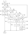
도 3은 본 발명의 바람직한 실시예에 따른 계전기를 포함한 모터 제어 방법을 나타낸 순서도이다.3 is a flowchart illustrating a motor control method including a relay according to a preferred embodiment of the present invention.
< 도면의 주요 부분에 대한 부호의 설명 ><Description of Symbols for Main Parts of Drawings>
1 : 보조회로 2 : 전자식 모터 보호용 릴레이부 1: Auxiliary circuit 2: Electronic motor protection relay
3 : 계전부 4 : CPU 3: relay unit 4: CPU
5 : 메모리부 6 : 모터 5: memory 6: motor
7 : 센서부 10 : 디스플레이부 7
11 : 입력부 11 input unit
본 발명은 모터 시스템에 관한 것이다. 더욱 상세하게는, 모터 제어를 위한 각종 버튼 및 모터 보호 계전기, 검사기, 콘트롤러 등이 기능을 일체화한 종합 디지털 모터 보호 제어 장치로서 계전기가 시스템에 일체화되어 있어 다양한 씨퀀스에 적용가능하며 자체 테스트 실시, CT실시, 수위조정이 사용자의 설정에 의해 자유롭게 설정/실시 할 수 있으며 설치 전선이 많이 들지않아 전력소모가 절감되며 계전기가 디지털 전자화 되어 있어 정확한 릴레이 동작과 정밀한 디지털 데이터를 얻어 낼 수 있고 전자 센서를 설치하고 있어 정확하고 오차없는 센싱이 가능한 계전기를 포함한 모터 시스템 및 방법에 관한 것이다.The present invention relates to a motor system. More specifically, it is a comprehensive digital motor protection control device in which various buttons for motor control, motor protection relay, tester, controller, etc. are integrated, and the relay is integrated in the system, so it can be applied to various sequences. Implementation and level adjustment can be freely set / executed by user's setting, and power consumption is reduced because there is not much installation wire, and relay is digitalized to obtain accurate relay operation and precise digital data, and to install electronic sensor. The present invention relates to a motor system and method including a relay capable of accurate and error-free sensing.
일반적으로, 계전기는 사이러트론·그릿글로관(管)·SCR 등도 계전기의 작용을 하지만, 보통 전자석을 사용하는 기계적인 것을 가리킨다. 입력신호에는 전류·전압·전력·주파수·위상 등의 전기적인 입력과 온도·빛 등 여러 가지 신호가 있다. 또 입력신호를 전기회로의 개폐로 바꾸는 데는 전자석에 의한 전자흡인력(電磁吸引力)·동전구동력(動電驅動力)·정전인력(靜電引力)·전기변형현상(電氣變形現象)·자기변형현상·열팽창현상·광전효과(光電效果) 등 여러 가지 물리현상을 이용하는 것을 생각할 수 있다. In general, the relay also refers to a mechanical system using an electromagnet, although a siretron, a grit globule tube, and an SCR also act as a relay. Input signals include electrical input such as current, voltage, power, frequency, and phase, and various signals such as temperature and light. Electromagnetic attraction, electromotive force, electrostatic attraction, electrical deformation, and magnetostriction phenomena by electromagnets are used to convert the input signal into opening and closing of an electric circuit. It is conceivable to use various physical phenomena such as thermal expansion and photoelectric effect.
그러나 고감도·고신뢰도 및 가볍고도 작으며 값이 싸야 한다는 점을 충족하는 것으로서 전자계전기가 있다. 이것은 전자석을 이용하는 것으로 무극(無極)전자 계전기와 유극(有極)전자계전기가 있으며, 가장 많이 사용되는 것은 무극전자계전기(보통 전자계전기라고 한다)인데, 전화의 자동교환기에 사용되고 있다. However, there are electromagnetic relays that satisfy high sensitivity, high reliability, light weight, small size, and low cost. This uses an electromagnet, and there are a poleless electromagnetic relay and a poleless electromagnetic relay, and the most common one is a poleless electromagnetic relay (commonly referred to as an electromagnetic relay), which is used in an automatic telephone exchange.
상기의 계전기는 모터와 결합되었을 때 모터를 보호하는 역할을 하는데 서로 일체로 되어 있지 않아 많은 전선이 사용됨으로써 전력소모가 증가하고 성능 테스트를 할 때 무거운 장비를 들고와 측정해야 하며 수위 조절을 할 때 자동제어가 이루어지지 않아 조종하는데 어려운 문제점이 있었다. The relay above protects the motor when it is combined with the motor. It is not integrated with each other, which increases the power consumption due to the use of many wires. There was a problem that it is difficult to control because the automatic control is not made.
이러한 문제점을 해결하기 위해 본 발명은 모터 제어를 위한 각종 버튼 및 모터 보호 계전기, 검사기, 콘트롤러 등이 기능을 일체화한 종합 디지털 모터 보호 제어 장치로서 계전기가 시스템에 일체화 되어 있어 다양한 씨퀀스에 적용가능하며 자체 테스트 실시, CT실시, 수위조정이 사용자의 설정에 의해 자유롭게 설정/실시 할 수 있으며 설치 전선이 많이 들지않아 전력소모가 절감되며 계전기가 디지털 전자화 되어 있어 정확한 릴레이 동작과 정밀한 디지털 데이터를 얻어 낼 수 있고 전자 센서를 설치하고 있어 정확하고 오차없는 센싱이 가능한 계전기를 포함한 모터 시스템 및 방법을 제공하는 것을 그 목적으로 한다.In order to solve this problem, the present invention is a comprehensive digital motor protection control device in which various buttons for motor control, motor protection relay, tester, controller, and the like are integrated, and the relay is integrated in the system, and thus it is applicable to various sequences. Test run, CT run, and water level adjustment can be freely set / executed by user's setting. Power consumption is reduced because there are not many installation wires, and relay is digitalized to obtain accurate relay operation and precise digital data. It is an object of the present invention to provide a motor system and method including a relay, which is equipped with an electronic sensor and enables accurate and error-free sensing.
이러한 목적을 달성하기 위하여, 본 발명은 모터 제어 시스템에 있어서, 3상전원을 받아 상기 모터(6)를 보호하며 전자식으로 동작하고 계전부(3); 보조회로(1)로 전기를 공급하는 전자식 모터 보호용 릴레이부(2); 상기 전자식 모터 보호용 릴레이부(2)로부터 신호를 받아 상기 계전부(3)에 신호를 보내 상기 계전부(3) 의 보조적 역할을 하는 보조회로(1); 상기 전자식 모터 보호용 릴레이부(2)로부터 전기를 받고 상기 보조회로(1)로부터 보조신호를 받아 상기 모터(6)를 구동하는 계전부(3); 상기 계전부(3)로부터 공급된 전기를 받아 3상으로 회전 운동을 하고 물을 퍼올리거나 공급하는 역할을 하는 모터(6); 상기 모터(6)와 연결되고 수위의 높이를 감지하며 감지된 신호를 CPU(4)에 보내는 센서부(7); 상기 장치들과 연결되어 상기 계전부(3)의 안정된 릴레이 동작과 상기 모터(6)를 제어하고 상기 센서부(7)로부터 받은 정보를 분석해서 제어에 반영하는 CPU(4); 상기 CPU(4)에서 제어시 발생되는 정보를 저장하고 보내는 역할을 하는 메모리부(5);를 포함하여 이루어진 것을 특징으로 한다.In order to achieve this object, the present invention provides a motor control system, which receives a three-phase power source, protects the motor (6) and operates electronically and includes a relay unit (3); An electronic motor protection relay unit 2 for supplying electricity to the
또한, 본 발명은 모터 제어 방법에 있어서, (a) 관리자가 입력부(11)를 통해서 데이터나 정보를 입력하면 CPU(4)가 입력된 설정값을 메모리부(5)에 저장하는 단계; (b) 시스템이 현재 설정된 상태가 일반모드인지 아닌지를 판단하는 단계;In addition, the present invention provides a motor control method comprising the steps of: (a) storing, by the manager (4), a setting value input by the CPU (4) in the memory unit (5) when the administrator inputs data or information through the input unit (11); (b) the system determining whether the currently set state is the normal mode or not;
(c) 시스템의 현재 설정 상태가 일반모드일 경우 메모리부(5)에 저장된 설정값을 CPU(4)에 전송하는 단계; (d) CPU(4)가 일반모드로 전환하여 모든 장치를 제어하는 상태로 들어가는 단계; (e) 상기 단계(b)에서 일반모드가 아닌 경우 시스템이 테스트 모드 상태인지를 판단하는 단계; (f) 시스템의 상태가 테스트 모드 상태이면 모의적으로 계전부(3)를 ON/OFF시키는 단계; (g) CPU(4)가 장치 테스트 상태로 전환하는 단계; (h) 테스트를 실시하는 단계; (i) 단계(e)에서 시스템 상태가 테스트 모드 상태가 아니면 시스템은 CT모드 상태인지를 판단하는 단계; (j) 시스템 상태가 CT모드 상태라면, CPU(4)가 CT모드로 전환되는 단계; (k) CPU(4)가 각 장치에 제어 신호를 전송하는 단계; (l) 시스템의 파라미터 설정값을 조종하는 단계; (m) 단계 (i)에서 시스템이 CT모드가 아닐경우 수위조정 모드인가를 판단하는 단계; (n) CPU(4)가 수위 조정 모드로 전환하는 단계; (o) 센서부(7)에서 수위를 센싱하는 단계; (p) CPU(4)는 센싱값에 따라서 모터를 가동하는 단계; (q) 단계(m)에서 시스템이 수위조정 모드가 아닌경우 단계(b)로 돌아가는 단계;를 포함하여 이루어진 것을 특징으로 한다.(c) transmitting the setting values stored in the
이하, 본 발명의 바람직한 실시예를 첨부된 도면들을 참조하여 상세히 설명한다. 우선 각 도면의 구성요소들에 참조부호를 부가함에 있어서, 동일한 구성요소들에 대해서는 비록 다른 도면상에 표시되더라도 가능한 한 동일한 부호를 가지도록 하고 있음에 유의해야 한다. 또한, 본 발명을 설명함에 있어서, 관련된 공지 구성 또는 기능에 대한 구체적인 설명이 본 발명의 요지를 흐릴 수 있다고 판단되는 경우에는 그 상세한 설명은 생략한다.Hereinafter, exemplary embodiments of the present invention will be described in detail with reference to the accompanying drawings. First of all, in adding reference numerals to the components of each drawing, it should be noted that the same reference numerals are used as much as possible even if displayed on different drawings. In addition, in describing the present invention, when it is determined that the detailed description of the related well-known configuration or function may obscure the gist of the present invention, the detailed description thereof will be omitted.
도 1은 본 발명의 바람직한 실시예에 따른 계전기를 포함한 모터 시스템을 나타내는 회로도이다.1 is a circuit diagram illustrating a motor system including a relay according to a preferred embodiment of the present invention.
도 1을 참조하면, 본 발명은 3상전원을 받아 모터를 보호하며 전자식으로 동작하고 계전부(3)와 보조회로(1)로 전기를 공급하는 전자식 모터 보호용 릴레이부(2); 전자식 모터 보호용 릴레이부(2)로부터 신호를 받아 계전부(3)에 신호를 보내 계전부(3)의 보조적 역할을 하는 보조회로(1); 전자식 모터 보호용 릴레이부(2) 로부터 전기를 받고 보조회로(1)로부터 보조신호를 받아 모터를 구동하는 계전부(3); 계전부(3)로부터 공급된 전기를 받아 3상으로 회전 운동을 하고 물을 퍼올리거나 공급하는 역할을 하는 모터(6); 모터(6)와 연결되고 수위의 높이를 감지하며 감지된 신호를 CPU(4)에 보내는 센서부(7); 상기 각 장치들과 연결되어 계전부(3)의 안정된 릴레이 동작과 모터(6)를 제어하고 센서부(7)로부터 받은 정보를 분석해서 제어에 반영하는 CPU(4); CPU(4)에서 제어시 발생되는 정보를 저장하고 보내는 역할을 하는 메모리부(5); 를 포함하여 이루어져 있다.Referring to FIG. 1, the present invention provides an electronic motor protection relay unit 2 that receives a three-phase power source, protects a motor, operates electronically, and supplies electricity to the
보조회로(1)는 전원으로부터 들어오는 3상전기를 감지해서 전자식 모터 보호용 릴레이부(2)로부터 들어오는 신호와 결합하여 계전부(3)로 결합된 정보를 보낸다. The
전자식 모터 보호용 릴레이부(2)는 전원으로부터 들어오는 3상전기를 받아 모터를 보호하고 전자식으로 동작한다. 또한 입력된 전기를 적절한 상태로 변환하여 계전부(3)로 전송한다. Electronic motor protection relay unit 2 receives the three-phase electric from the power source to protect the motor and operates electronically. In addition, the input electricity is converted into an appropriate state and transmitted to the
계전부(3)는 전자식 모터 보호용 릴레이부(2)로부터 들어온 전기를 받아 보조회로(1)의 결합된 신호를 이용해 적절한 전기를 생성하고 각 동작 모드에 따라 CPU(4)의 제어에 의해 모터(6)를 구동한다.The
또한, 상기한 바와 같이 본 발명에서는 계전부(3)을 모터 제어 시스템에 일체화 시켜 사용 전선과 소비전력을 대폭적으로 감축할 수 있는데 CPU(4)와 모터(6) 사이에서 동작에 참여하여 시스템의 안정을 가져주며 신속한 처리와 전력의 낭비를 방지하도록 하는 역할을 한다.In addition, as described above, in the present invention, the
또한, 상기 계전기(3)은 기계식이 아닌 디지털 전자식으로 릴레이 동작 오류가 적으며 동작 데이터를 디지털로 확인할 수 있어 시스템 테스트시 정확한 결과를 도출해 낼 수 있도록하며 CPU(4)의 동작에 일조하는 역할을 한다.In addition, the relay (3) is a digital electronic, not mechanical, the relay operation error is small, the operation data can be digitally confirmed to derive the correct results when testing the system and serves to contribute to the operation of the CPU (4) do.
CPU(4)는 각 장치들과 연결되어 계전부(3)의 안정된 릴레이 동작과 모터(6)를 제어하고 센서부(7)로부터 받은 정보를 분석해서 제어에 반영하며 생성된 정보를 메모리부(5)로 보내 보관하고 테스트나, CT시 메모리부(5)로부터 정보를 인출해 사용한다. The
메모리부(5)는 CPU(4)로부터 보내온 정보를 저장하고 보관하다가 CPU(4)가 정보를 요구할 때 데이터를 보내주는 역할을 한다.The
모터(6)는 계전부(3)에서 보내온 전기를 받아 동작하며 CPU(4)에 의해 제어된다. 또한, 센서부(7)의 센싱 결과에 의해 구동되며 여기서는 3상모터를 사용한다.The
센서부(7)는 배관이나 수통에 있는 물의 량을 센싱하여 센싱된 정보를 CPU(4)에 보내서 CPU(4)가 수위 정보를 토대로 모터(6)를 제어하도록 한다.The
또한, 상기 센서부(7)는 감지판에 전자적으로 동작하는 감지 센서가 달려 있어 정확한 센싱이 가능하며 시스템 테스트시 디지털화한 데이터를 만들어내는 효율적인 센싱 동작이 가능하다.In addition, the
또한, 수위 조절시 수위를 민감한 디지털 전자 센서로 측정하여 수위의 움직임을 민감하고 정확하게 감지해내는 역할을 한다.In addition, the water level is measured by a sensitive digital electronic sensor to adjust the water level sensitively and accurately.
도 2는 본 발명의 바람직한 실시예에 따른 계전기를 포함한 모터 시스템을 나타낸 블럭도이다.2 is a block diagram showing a motor system including a relay according to a preferred embodiment of the present invention.
도 2를 참조하면, 본 발명은 CPU(4)와 송수신을 하며 모터(6)을 보호하는 계전부(3); CPU(4)의 제어를 받으며 물을 퍼올리거나 보내는 역할을 하는 모터(6); 키보드나 패드와 같은 것으로 본 시스템에 설정을 입력하는 입력부(11); CPU(4)에서 발생된 정보를 출력해주는 디스플레이부(10); CPU(4)에서 발생된 정보를 저장하고 보관하고 있다가 필요할 경우 정보를 전송해주는 메모리부(5); 물의 높이나 상태를 센싱하여 센싱된 정보를 CPU(4)에 전송하고 모터(6)의 구동에 필요한 정보를 생성하는 센서부(7);를 포함하여 이루져있다.Referring to FIG. 2, the present invention includes a
상기 계전부(3), CPU(4), 메모리부(5), 모터(6), 센서부(7)는 도 1에서 설명하였으므로 여기서는 생략한다.Since the
디스플레이부(10)는 시스템에서 발생하는 정보를 관리자가 인식할 수 있도록 출력하는 역할을 하는데 모니터, LCD, LED 등이 사용된다.The
입력부(11)는 관리자가 시스템에 설정을 하거나 검사 및 CT를 할 때 정보를 입력하는 수단으로 사용된다. The
도 3은 본 발명의 바람직한 실시예에 따른 계전기를 포함한 모터 제어 방법을 나타낸 순서도이다.3 is a flowchart illustrating a motor control method including a relay according to a preferred embodiment of the present invention.
도 3을 참조하면, 관리자가 입력부(11)를 통해서 데이터나 정보를 입력하면 CPU(4)는 이렇게 입력된 설정값을 메모리부(5)에 저장한다(S10). Referring to FIG. 3, when an administrator inputs data or information through the
시스템은 현재 설정된 상태가 일반모드인지 아닌지를 판단하게 된다(S20).The system determines whether the currently set state is the normal mode (S20).
만일, 일반모드일 경우 메모리부(5)에 저장된 설정값을 CPU(4)에 전송한다(S30). In case of the normal mode, the setting value stored in the
CPU(4)는 일반모드로 전환하여 모든 장치를 제어하는 상태로 들어간다(S40).The
만일, 상기 단계 S20에서 일반모드가 아닌 경우 시스템은 테스트 모드 상태인지를 판단하게 된다(S50). If it is not the normal mode in step S20, the system determines whether the test mode state (S50).
시스템의 상태가 테스트 모드 상태이면 모의적으로 계전부(3)를 ON/OFF시킨다(S60). If the state of the system is the test mode state, the
그리고 CPU(4)는 계전부(3)에 의해 장치 테스트 상태로 전환된다(S70). 테스트 모드로 설정된 시스템은 테스트를 하게 된다(S80).The
여기서 테스트 모드란 TRIP SIMULATION이라고도 하는데 가상의 임의의 허 부하를 모터(6)에 인가하여 시스템이 국제 규격의 프로텍션 커브(Protection Curve)로 정상 동작하는지 여부를 실제 부하를 인가하지 않고 테스트를 할 수 있는 기능이다.Here, the test mode is also called TRIP SIMULATION. By applying a virtual arbitrary load to the
이 기능을 사용함으로써 번거롭고 무거운 테스트 장비를 휴대하지 않고 시스템의 정상 유무 등을 손쉽게 확인할 수 있을 뿐 아니라, 외부 환경 변화로 인한 스시템의 오동작을 조기 발견하고 이를 조치하여 예상치 못한 대형 사고를 미연에 방지할 수 있는 장점이 있다. By using this function, it is not only easy to check whether the system is normal without carrying cumbersome and heavy test equipment, but also detects and malfunctions of the system due to changes in the external environment early and prevents unexpected large accidents. There is an advantage to this.
상기 단계 S50에서 시스템 상태가 테스트 모드 상태가 아니면 시스템은 CT모드 상태인지를 판단하게 된다(S90).If the system state is not the test mode state in step S50, the system determines whether the CT mode state (S90).
만일 시스템 상태가 CT모드 상태라면, CPU(4)는 계전부(3)에 의해 CT모드로 전환된다(S100). If the system state is the CT mode state, the
여기서 CT모드는 CT변경으로 인하여 생긴 내부 오차를 보정해 주기 위하 기능으로 시스템 내부와 연산 파라미터를 자동으로 설정 변경하는 기능이다.Here, CT mode is a function to correct the internal error caused by CT change and to automatically change the system internal and arithmetic parameters.
또한 다양한 CT 오차 및 시스템에 대한 오차를 해결하여 시스템의 정밀도를 높여 줄 수 있다.In addition, it is possible to increase the precision of the system by solving various CT errors and errors for the system.
다음으로 CPU(4)는 계전부(3)과 연동하여 각 장치에 제어 신호를 전송한다(S101). 그리고 시스템의 파라미터 설정값을 조종한다(S102). Next, the
상기 단계 S90에서 시스템이 CT모드가 아닐경우 수위조정 모드인가를 판단한다(S103).In step S90, if the system is not in the CT mode, it is determined whether the water level adjustment mode (S103).
시스템이 수위조정 모드이면 CPU(4)가 계전부(3)와 연동해 수위조정 모드로 전환된다(S104).If the system is in the water level adjustment mode, the
여기서 수위조정 모드는 수위가 변동하여 수위가 일정지점만큼 내려갔을 때 이를 감지하여 센서부(7)가 이를 감지해 관리자가 모터를 기동하여 적정 수위까지 증가 시켜줄 수 있게 하는 기능이다. Here, the water level adjustment mode is a function that detects when the water level is lowered by a certain point because the water level fluctuates, and the
다음단계로 센서부(7)에서는 감지판에 설치되어 있는 디지털 전자센서의 감지에 의해 정확한 수위를 센싱한다(S105). 그리고 CPU(4)는 디지털 센싱값에 따라서 모터를 가동한다(S106).In the next step, the
이상의 설명은 본 발명의 기술 사상을 예시적으로 설명한 것에 불과한 것으 로서, 본 발명이 속하는 기술 분야에서 통상의 지식을 가진 자라면 본 발명의 본질적인 특성에서 벗어나지 않는 범위에서 다양한 수정 및 변형이 가능할 것이다. 따라서, 본 발명에 개시된 실시예들은 본 발명의 기술 사상을 한정하기 위한 것이 아니라 설명하기 위한 것이고, 이러한 실시예에 의하여 본 발명의 기술 사상의 범위가 한정되는 것은 아니다. 본 발명의 보호 범위는 아래 청구범위에 의하여 해석되어야 하며, 그와 동등한 범위 내에 있는 모든 기술 사상은 본 발명의 권리범위에 포함되는 것으로 해석되어야 할 것이다.The above description is merely illustrative of the technical idea of the present invention, and those skilled in the art to which the present invention pertains may make various modifications and changes without departing from the essential characteristics of the present invention. Therefore, the embodiments disclosed in the present invention are not intended to limit the technical idea of the present invention but to describe the present invention, and the scope of the technical idea of the present invention is not limited by these embodiments. The scope of protection of the present invention should be interpreted by the following claims, and all technical ideas within the scope equivalent thereto should be construed as being included in the scope of the present invention.
이상에서 설명한 바와 같이 본 발명에 의하면, 모터 제어를 위한 각종 버튼 및 모터 보호 계전기, 검사기, 콘트롤러 등이 기능을 일체화한 종합 디지털 모터 보호 제어 장치로서 계전기가 시스템에 일체화 되어 있어 다양한 씨퀀스에 적용가능하며 자체 테스트 실시, CT실시, 수위조정이 사용자의 설정에 의해 자유롭게 설정/실시 할 수 있으며 설치 전선이 많이 들지않아 전력소모가 절감되며 계전기가 디지털 전자화 되어 있어 정확한 릴레이 동작과 정밀한 디지털 데이터를 얻어 낼 수 있고 전자 센서를 설치하고 있어 정확하고 오차없는 센싱이 가능한 효과가 있다.As described above, according to the present invention, as a total digital motor protection control device in which various buttons for motor control, motor protection relay, tester, controller, and the like are integrated, the relay is integrated in the system, and thus it is applicable to various sequences. Self test, CT, water level adjustment can be freely set / executed by user's setting. Power consumption is reduced because there is not much installation wire, and relay is digitalized to obtain accurate relay operation and precise digital data. In addition, the electronic sensor is installed to enable accurate and error-free sensing.
Claims (6)
Priority Applications (1)
| Application Number | Priority Date | Filing Date | Title |
|---|---|---|---|
| KR1020070043551A KR20080098191A (en) | 2007-05-04 | 2007-05-04 | Motor system and method including relay |
Applications Claiming Priority (1)
| Application Number | Priority Date | Filing Date | Title |
|---|---|---|---|
| KR1020070043551A KR20080098191A (en) | 2007-05-04 | 2007-05-04 | Motor system and method including relay |
Publications (1)
| Publication Number | Publication Date |
|---|---|
| KR20080098191A true KR20080098191A (en) | 2008-11-07 |
Family
ID=40285766
Family Applications (1)
| Application Number | Title | Priority Date | Filing Date |
|---|---|---|---|
| KR1020070043551A Ceased KR20080098191A (en) | 2007-05-04 | 2007-05-04 | Motor system and method including relay |
Country Status (1)
| Country | Link |
|---|---|
| KR (1) | KR20080098191A (en) |
Cited By (1)
| Publication number | Priority date | Publication date | Assignee | Title |
|---|---|---|---|---|
| KR101276919B1 (en) * | 2011-08-19 | 2013-06-19 | 엘에스산전 주식회사 | Method for testing electromechanical relay and electromechanical relay therefor |
-
2007
- 2007-05-04 KR KR1020070043551A patent/KR20080098191A/en not_active Ceased
Cited By (1)
| Publication number | Priority date | Publication date | Assignee | Title |
|---|---|---|---|---|
| KR101276919B1 (en) * | 2011-08-19 | 2013-06-19 | 엘에스산전 주식회사 | Method for testing electromechanical relay and electromechanical relay therefor |
Similar Documents
| Publication | Publication Date | Title |
|---|---|---|
| JP6505774B2 (en) | How to monitor building power usage | |
| CN103344913B (en) | A kind of electromagnetic relay checkout equipment and method | |
| CN100543648C (en) | Method and system for power management | |
| US11721513B2 (en) | Remote load switching circuit breaker | |
| CN101907689B (en) | Generation method and device of test circuit and power supply testing system | |
| CN107943130A (en) | control device with current protection solid-state relay | |
| KR102034894B1 (en) | Management system for circuit breakers in switchboard | |
| US8063763B2 (en) | System for testing NAC operability using reduced operating voltage | |
| TW201429096A (en) | Digital protection relay, digital protection relay test device, and method for testing digital protection relay | |
| JP2010259254A (en) | Current control device and protection device | |
| CN104483567A (en) | 500kV line relay protection device detection method and system | |
| CN112578274B (en) | Circuit breaker and mobile device | |
| KR101044536B1 (en) | Method and apparatus for determining power consumption of electronic switches, and method for controlling inverter and wind turbine | |
| KR20150017256A (en) | Apparatus for testing valve base electronics | |
| JP2009200815A (en) | Electronic device and control method thereof | |
| KR20080098191A (en) | Motor system and method including relay | |
| JP5931143B2 (en) | Isolated operation detection function evaluation test equipment | |
| KR100857393B1 (en) | Remote control device and method of air circuit breaker | |
| JP2007236101A (en) | Test apparatus and test method for isolated operation detection device | |
| KR20200116632A (en) | Power Control System | |
| KR20170124033A (en) | Power measuring system | |
| JP6420984B2 (en) | Power conditioner, terminal device, and soundness confirmation method | |
| CN103544911A (en) | Electronic device | |
| CN104836222B (en) | With the method and apparatus of power management in ETU in breaker when host | |
| TWI374272B (en) | Current consumption measurement system and method thereof |
Legal Events
| Date | Code | Title | Description |
|---|---|---|---|
| A201 | Request for examination | ||
| PA0109 | Patent application |
Patent event code: PA01091R01D Comment text: Patent Application Patent event date: 20070504 |
|
| PA0201 | Request for examination | ||
| E902 | Notification of reason for refusal | ||
| PE0902 | Notice of grounds for rejection |
Comment text: Notification of reason for refusal Patent event date: 20080929 Patent event code: PE09021S01D |
|
| PG1501 | Laying open of application | ||
| E601 | Decision to refuse application | ||
| PE0601 | Decision on rejection of patent |
Patent event date: 20081229 Comment text: Decision to Refuse Application Patent event code: PE06012S01D Patent event date: 20080929 Comment text: Notification of reason for refusal Patent event code: PE06011S01I |