KR20080068526A - Wavelength converting structure and manufacture and use of the same - Google Patents
Wavelength converting structure and manufacture and use of the same Download PDFInfo
- Publication number
- KR20080068526A KR20080068526A KR1020070120003A KR20070120003A KR20080068526A KR 20080068526 A KR20080068526 A KR 20080068526A KR 1020070120003 A KR1020070120003 A KR 1020070120003A KR 20070120003 A KR20070120003 A KR 20070120003A KR 20080068526 A KR20080068526 A KR 20080068526A
- Authority
- KR
- South Korea
- Prior art keywords
- coating
- wavelength
- wavelength converting
- adhesive
- converting structure
- Prior art date
Links
Images


Classifications
-
- G—PHYSICS
- G02—OPTICS
- G02F—OPTICAL DEVICES OR ARRANGEMENTS FOR THE CONTROL OF LIGHT BY MODIFICATION OF THE OPTICAL PROPERTIES OF THE MEDIA OF THE ELEMENTS INVOLVED THEREIN; NON-LINEAR OPTICS; FREQUENCY-CHANGING OF LIGHT; OPTICAL LOGIC ELEMENTS; OPTICAL ANALOGUE/DIGITAL CONVERTERS
- G02F1/00—Devices or arrangements for the control of the intensity, colour, phase, polarisation or direction of light arriving from an independent light source, e.g. switching, gating or modulating; Non-linear optics
- G02F1/01—Devices or arrangements for the control of the intensity, colour, phase, polarisation or direction of light arriving from an independent light source, e.g. switching, gating or modulating; Non-linear optics for the control of the intensity, phase, polarisation or colour
- G02F1/13—Devices or arrangements for the control of the intensity, colour, phase, polarisation or direction of light arriving from an independent light source, e.g. switching, gating or modulating; Non-linear optics for the control of the intensity, phase, polarisation or colour based on liquid crystals, e.g. single liquid crystal display cells
- G02F1/133—Constructional arrangements; Operation of liquid crystal cells; Circuit arrangements
- G02F1/1333—Constructional arrangements; Manufacturing methods
- G02F1/1335—Structural association of cells with optical devices, e.g. polarisers or reflectors
-
- H—ELECTRICITY
- H01—ELECTRIC ELEMENTS
- H01J—ELECTRIC DISCHARGE TUBES OR DISCHARGE LAMPS
- H01J1/00—Details of electrodes, of magnetic control means, of screens, or of the mounting or spacing thereof, common to two or more basic types of discharge tubes or lamps
- H01J1/54—Screens on or from which an image or pattern is formed, picked-up, converted, or stored; Luminescent coatings on vessels
- H01J1/62—Luminescent screens; Selection of materials for luminescent coatings on vessels
- H01J1/64—Luminescent screens; Selection of materials for luminescent coatings on vessels characterised by the binder or adhesive for securing the luminescent material to its support
-
- C—CHEMISTRY; METALLURGY
- C09—DYES; PAINTS; POLISHES; NATURAL RESINS; ADHESIVES; COMPOSITIONS NOT OTHERWISE PROVIDED FOR; APPLICATIONS OF MATERIALS NOT OTHERWISE PROVIDED FOR
- C09K—MATERIALS FOR MISCELLANEOUS APPLICATIONS, NOT PROVIDED FOR ELSEWHERE
- C09K11/00—Luminescent, e.g. electroluminescent, chemiluminescent materials
- C09K11/02—Use of particular materials as binders, particle coatings or suspension media therefor
-
- C—CHEMISTRY; METALLURGY
- C09—DYES; PAINTS; POLISHES; NATURAL RESINS; ADHESIVES; COMPOSITIONS NOT OTHERWISE PROVIDED FOR; APPLICATIONS OF MATERIALS NOT OTHERWISE PROVIDED FOR
- C09K—MATERIALS FOR MISCELLANEOUS APPLICATIONS, NOT PROVIDED FOR ELSEWHERE
- C09K11/00—Luminescent, e.g. electroluminescent, chemiluminescent materials
- C09K11/08—Luminescent, e.g. electroluminescent, chemiluminescent materials containing inorganic luminescent materials
-
- H—ELECTRICITY
- H01—ELECTRIC ELEMENTS
- H01J—ELECTRIC DISCHARGE TUBES OR DISCHARGE LAMPS
- H01J1/00—Details of electrodes, of magnetic control means, of screens, or of the mounting or spacing thereof, common to two or more basic types of discharge tubes or lamps
- H01J1/54—Screens on or from which an image or pattern is formed, picked-up, converted, or stored; Luminescent coatings on vessels
- H01J1/62—Luminescent screens; Selection of materials for luminescent coatings on vessels
- H01J1/68—Luminescent screens; Selection of materials for luminescent coatings on vessels with superimposed luminescent layers
-
- B—PERFORMING OPERATIONS; TRANSPORTING
- B82—NANOTECHNOLOGY
- B82Y—SPECIFIC USES OR APPLICATIONS OF NANOSTRUCTURES; MEASUREMENT OR ANALYSIS OF NANOSTRUCTURES; MANUFACTURE OR TREATMENT OF NANOSTRUCTURES
- B82Y20/00—Nanooptics, e.g. quantum optics or photonic crystals
-
- Y—GENERAL TAGGING OF NEW TECHNOLOGICAL DEVELOPMENTS; GENERAL TAGGING OF CROSS-SECTIONAL TECHNOLOGIES SPANNING OVER SEVERAL SECTIONS OF THE IPC; TECHNICAL SUBJECTS COVERED BY FORMER USPC CROSS-REFERENCE ART COLLECTIONS [XRACs] AND DIGESTS
- Y10—TECHNICAL SUBJECTS COVERED BY FORMER USPC
- Y10T—TECHNICAL SUBJECTS COVERED BY FORMER US CLASSIFICATION
- Y10T428/00—Stock material or miscellaneous articles
- Y10T428/26—Web or sheet containing structurally defined element or component, the element or component having a specified physical dimension
- Y10T428/263—Coating layer not in excess of 5 mils thick or equivalent
- Y10T428/264—Up to 3 mils
- Y10T428/265—1 mil or less
Landscapes
- Chemical & Material Sciences (AREA)
- Physics & Mathematics (AREA)
- Engineering & Computer Science (AREA)
- Materials Engineering (AREA)
- Organic Chemistry (AREA)
- Nonlinear Science (AREA)
- Mathematical Physics (AREA)
- Crystallography & Structural Chemistry (AREA)
- Inorganic Chemistry (AREA)
- General Physics & Mathematics (AREA)
- Optics & Photonics (AREA)
- Luminescent Compositions (AREA)
- Coating Of Shaped Articles Made Of Macromolecular Substances (AREA)
- Laminated Bodies (AREA)
- Led Devices (AREA)
Abstract
Description
본 발명은 파장 변환 구조(wavelength converting structure)에 관한 것이다. 더욱 특히, 본 발명은 280 nm 이하(즉 UVC)의 파장을 갖는 자외선을 가시광으로 변환할 수 있는 파장 변환 코팅을 포함하는 구조에 관한 것이다. 상기 코팅은 UVc 광원과 조합 사용되어 공기 존재하에서 UVc 파장을 가시광 파장으로 변환할 수 있다. 파장 변환 구조를 제조하기 위한 단계는 간단하다. 대형 방출 영역을 갖는 평탄한 광원도 마찬가지로 간단하게 제조될 수 있다. 또한, 본 발명은 발광(light emission) 모듈 및 백라이트(backlight) 모듈의 파장 변환 구조를 적용하는 것에도 관한 것이다. The present invention relates to a wavelength converting structure. More particularly, the present invention relates to a structure comprising a wavelength converting coating capable of converting ultraviolet light having a wavelength of 280 nm or less (ie UV C ) into visible light. The coating can be used in combination with a UVc light source to convert UVc wavelengths into visible light wavelengths in the presence of air. The steps for manufacturing the wavelength conversion structure are simple. Flat light sources with large emission areas can likewise be produced simply. The invention also relates to the application of wavelength converting structures of a light emission module and a backlight module.
디스플레이에 사용되는 광원은 대형 방출 영역을 갖고 점점 평탄해지는 경향이 있다. 대형 방출 영역을 갖는 평탄한 광원은 대규모 평탄 패널 액정 디스플레이에서 백라이트 모듈에 아주 중요하다. 다양한 통상적인 광원의 경우, 에너지/파장 변환을 통하여 가시광을 제공하기 위해 현재 사용되는 수단은 냉음극 형광램 프(CCFL), 외부 전극 형광 램프(EEFL), 발광 다이오드(LED), 탄소 나노튜브 (CNT), 평탄 형광 램프(FFL), 및 유기 발광 디스플레이(OLED)를 포함한다. Light sources used in displays tend to have a large emission area and become flatter. Flat light sources with large emission areas are of great importance for backlight modules in large scale flat panel liquid crystal displays. For various conventional light sources, the means currently used to provide visible light through energy / wavelength conversion are cold cathode fluorescent lamps (CCFL), external electrode fluorescent lamps (EEFL), light emitting diodes (LEDs), carbon nanotubes ( CNTs), flat fluorescent lamps (FFL), and organic light emitting displays (OLEDs).
상술한 방법 중에서, CCFL 수법은 유리 튜브의 내벽 상에 인층(phosphor layer) 코팅을 포함한다. 형광 튜브에는 소량의 불활성 가스 및 Hg 증기도 또한 캡슐화된다. 이어, 전극 방전 과정 동안, Hg 증기는 전자 영향으로 인하여 자외선을 방출한다. 이어 자외선은 튜브 벽 상의 인층에 의해 가시광으로 변환되어, 가시광 파장을 제공한다. CCFL 수법은 향상된 제조 기술, 비교적 저렴한 비용 등과 같은 다수의 이점을 제공한다. 그러나, 인 코팅 및 발광 광원은 동일 진공 램프 튜브에 배치되어야 하므로, 대규모 램프를 제조하여 대규모 영역에서 파장 변환을 허용하기가 어렵다. 또한, 램프 튜브를 연장시키는 것에 의해 더 대규모의 발광 영역을 얻으면, 낮은 제조 수율 및 실질적인 비용 증가와 같은 여러 결점이 존재한다. Among the methods described above, the CCFL technique includes a phosphor layer coating on the inner wall of the glass tube. Small amounts of inert gas and Hg vapor are also encapsulated in the fluorescent tube. Subsequently, during the electrode discharge process, the Hg vapor emits ultraviolet rays due to the electron effect. The ultraviolet light is then converted into visible light by the phosphorus on the tube wall, providing a visible light wavelength. CCFL techniques offer many advantages, such as improved manufacturing techniques, relatively low cost, and the like. However, since the phosphorus coated and luminescent light sources must be placed in the same vacuum lamp tube, it is difficult to fabricate large scale lamps and allow wavelength conversion in large scale regions. In addition, obtaining a larger light emitting area by extending the lamp tube presents several drawbacks such as low manufacturing yield and substantial cost increase.
EEFL는 전극이 주로 램프 튜브 밖에 배치되어서 다수의 형광 램프 튜브가 동일 변환기에 의해 구동될 수 있어 비용이 감소되고 전력 효율이 더 높은 점에서 CCFL과 상이하다. 그러나, EEFL의 적용시 제한점은 여전히 존재한다. 예컨대, EEFL 램프가 부적절한 밝기를 내고 또 증가된 램프 튜브 전압하에서 전류가 증가되어 출력 밝기를 향상시키면, 변환기의 크기는 급격하게 증가할 것이다. 그 결과, 열 손실이 불량하게 될 것이다. 또한, CCFL과 마찬가지로, EEFL은 또한 대규모 발광 영역을 제공할 수 없다. EEFLs differ from CCFLs in that the electrodes are placed primarily outside the lamp tube, allowing multiple fluorescent lamp tubes to be driven by the same converter, reducing costs and providing higher power efficiency. However, there are still limitations in the application of the EEFL. For example, if the EEFL lamp produces inadequate brightness and the current is increased under an increased lamp tube voltage to improve the output brightness, the size of the transducer will increase dramatically. As a result, the heat loss will be poor. In addition, like the CCFL, the EEFL also cannot provide a large emission area.
LED는 반도체 물질로 제조된 발광 장치이다. III-V족 화합물(예컨대, GaP, GaAs 등)이 원료로 사용된다. 전류를 반도체 화합물에 적용하는 것을 통하여, LED 는 전자 및 정공(hole)의 조합 결과로서 광을 방출할 수 있다. LED는 부피가 적고, 사용 수명이 길고, 구동 전압이 낮고 또 응답 속도가 신속한 것을 특징으로 한다. 불행히도, LED는 색 혼합 부정확성, 고 제조비용, 열등한 균일성, 불량한 열손실 및 낮은 전력 효율과 같은 일부 결점을 여전히 갖고 있다. LEDs are light emitting devices made of semiconductor materials. Group III-V compounds (eg GaP, GaAs, etc.) are used as raw materials. By applying a current to the semiconductor compound, the LED can emit light as a result of the combination of electrons and holes. LEDs are characterized by small volume, long service life, low drive voltage and fast response speed. Unfortunately, LEDs still have some drawbacks, such as color mixing inaccuracies, high manufacturing costs, poor uniformity, poor heat loss and low power efficiency.
CNT에서, 전자는 강력한 전계를 이용하여 선단으로부터 방출되며, 또 높은 전압에 의해 가속되어 형광판에 영향을 주어, 광 파장 에너지를 생성한다. CNT는 낮은 전력 소모, 저온 작동, 및 Hg 결여와 같은 이점을 갖고 있지만, CNT는 복잡한 제조공정, 고비용, 불량한 밝기 안정성, 및 열등한 균일성과 같은 문제를 여전히 갖고 있다. 또한 대규모 CNT 제조를 위한 제조 수법이 아직 개발중이다. In CNTs, electrons are emitted from the tip using a strong electric field and are accelerated by high voltages to affect the fluorescent plate, producing light wavelength energy. CNTs have advantages such as low power consumption, low temperature operation, and lack of Hg, but CNTs still have problems such as complex manufacturing processes, high cost, poor brightness stability, and poor uniformity. In addition, manufacturing techniques for large-scale CNT production are still under development.
FFL은 불활성 가스의 방출로부터 생성된 자외선을 이용하여 착색 인 분말을 여기시킨 다음 인간 눈에 가시적인 광 파장을 생성한다. 유사하게, FFL은 Hg의 결여, 긴 사용수명 및 단순화된 광학 디자인과 같은 이점을 갖고 있지만, FFL은 여전히 복잡한 제조공정, 높은 제조비용, 저효율 및 불량한 열 손실과 같은 문제를 제공하고 있다. FFL uses ultraviolet light generated from the release of an inert gas to excite colored phosphorous powder and then produce a light wavelength visible to the human eye. Similarly, while FFL has advantages such as lack of Hg, long service life and simplified optical design, FFL still presents problems such as complex manufacturing processes, high manufacturing costs, low efficiency and poor heat loss.
OLED에서, 바이어스 전압(biasing voltage)은 양극/음극으로부터 전자/정공 주입을 구동하도록 외부적으로 인가되어 전계 존재하에서 정공 및 전자는 재결합을 위해 서로에 대하여 이동할 것이다. 그 결과, 광 파장의 에너지가 방출될 것이다. OLED는 박형 구조(thinner structure), 더 밝음, 더 넓은 작업 온도 범위, 더 낮은 전력 소모 및 더 낮은 구동 전압을 특징으로 하지만, 현재 입수되는 OLED는 대규모 모델 제조의 어려움, 높은 제조 비용, 낮은 효율 및 짧은 사용수명과 같은 문제가 있다. In OLEDs, a biasing voltage is applied externally to drive electron / hole injection from the anode / cathode so that holes and electrons will move relative to each other for recombination in the presence of an electric field. As a result, energy of the light wavelength will be emitted. OLEDs feature thinner structures, brighter, wider working temperature ranges, lower power consumption and lower drive voltages, but currently available OLEDs have the difficulty of manufacturing large models, high manufacturing costs, low efficiency and There are problems such as short service life.
상술한 기재로부터 가시광의 기존 공급원은 제조 기술 면에서 성숙성이 결여(LED, CNT, OLED 및 FFL)되거나, 또는 제조시 본연의 제한으로 인하여 대규모 제조가 방지되는 것을 알 수 있으며, 단순하고 저렴한 수단을 이용하여 대규모로 광을 변환하는데 실패하고 있다. It can be seen from the above-mentioned substrate that existing sources of visible light lack maturity in manufacturing technology (LED, CNT, OLED and FFL) or that large-scale manufacturing is prevented due to the inherent limitations in manufacturing, and simple and inexpensive means. Fail to convert light on a large scale using
상술한 관점에서, 본 발명은 기존의 수법과 조합하여 간단한 방법을 이용하여 대규모로 파장 변환하는 방법을 제공한다. In view of the foregoing, the present invention provides a method for converting wavelengths on a large scale using a simple method in combination with existing methods.
본 발명에서, 용어 "UVC"는 280 nm 이하의 파장을 갖는 자외선을 지칭한다. 200 nm 내지 280 nm, 특히 250 nm 내지 260 nm 범위의 파장이 바람직하다. 253.7 nm 파장이 가장 좋다. 용어 "UVB"는 280 nm 내지 320 nm 파장 범위의 광선을 지칭하는 반면에, "UVA"는 320 nm 내지 400 nm 범위의 파장을 갖는 광선을 지칭한다. 용어 "고분자 접착제"는 올리고머 및 중합체를 비롯한 1000 이상의 분자량을 갖는 분자를 지칭한다. 용어 "자외선(또는 UVC, UVA 또는 UVB)"에 의해 여기될 수 있는 인"은 자외선(또는 UVC, UVA 또는 UVB)를 흡수하며 자외선(또는 UVC, UVA 또는 UVB)에 의해 조사되면 가시광을 방출하는 물질을 지칭한다. In the present invention, the term "UV C " refers to ultraviolet light having a wavelength of 280 nm or less. Preference is given to wavelengths in the range of 200 nm to 280 nm, especially 250 nm to 260 nm. The 253.7 nm wavelength is best. The term “UV B ” refers to light rays in the range of 280 nm to 320 nm, while “UV A ” refers to light rays having a wavelength in the range of 320 nm to 400 nm. The term "polymer adhesive" refers to a molecule having a molecular weight of at least 1000, including oligomers and polymers. The term "ultraviolet (or UV C, UV A or UV B)" is ", which can be excited by absorbs an ultraviolet (or UV C, UV A or UV B) an ultraviolet (or UV C, UV A or UV B When irradiated by) refers to a material that emits visible light.
본 발명의 일개 목적은, One object of the present invention,
기판; 및 Board; And
기판 상에 배치되며 또 Disposed on the substrate and
(a) UVC에 의해 여기될 수 있는 인 분말; 및 (a) phosphorus powders that can be excited by UV C ; And
(b) 항-UVC 접착제를 포함하는 파장 변환 코팅을 포함하는 파장 변환 구조로서, 상기 파장 변환 코팅의 두께는 인 분말의 평균 입자 크기의 약 2 내지 약 10배이고, 파장 변환 코팅 중의 인 분말의 양은, (b) a wavelength converting structure comprising a wavelength converting coating comprising an anti-UV C adhesive, wherein the thickness of the wavelength converting coating is about 2 to about 10 times the average particle size of the phosphor powder, German silver,
(i) 인 분말은 인 분말과 접착제의 전체 용적을 기준으로 하여 파장 변환 코팅의 약 30 용적% 내지 약 85 용적%이고; 또 (i) the phosphor powder is about 30% to about 85% by volume of the wavelength conversion coating based on the total volume of the phosphor powder and the adhesive; In addition
(ii) 인 분말 대 접착제의 중량비가 약 1:1 내지 약 20:1 범위인 요건 중의 적어도 하나를 만족하는 파장 변환 구조를 제공하는 것이다. (ii) provide a wavelength converting structure that satisfies at least one of the requirements that the weight ratio of phosphorus powder to adhesive ranges from about 1: 1 to about 20: 1.
UVC 광원과 조합하여, 본 발명의 파장 변환 구조는 큰 영역의 평탄한 가시광원을 제공할 수 있다. 이러한 가시광원은 백라이트 모듈에 사용되어 간단한 수단에 의해 큰 영역의 디스플레이 패널을 제공할 수 있다. UV C In combination with the light source, the wavelength conversion structure of the present invention can provide a flat visible light source of a large area. Such a visible light source can be used in a backlight module to provide a large area display panel by simple means.
본 발명의 다른 목적은, Another object of the present invention,
기판을 제공하는 단계; Providing a substrate;
기판의 표면 상에 슬러리를 코팅하는 단계; 및 Coating the slurry on the surface of the substrate; And
코팅된 기판을 건조시키는 단계를 포함하며, Drying the coated substrate,
상기 슬러리는 저장 용기 내에 위치하고 또 The slurry is located in a storage vessel and
(a) UVC에 의해 여기될 수 있는 인 분말; 및 (a) phosphorus powders that can be excited by UV C ; And
(b) 항-UVC 접착제; 및 (b) anti-UV C adhesive; And
(c) 유기 용매를 포함하며, (c) comprises an organic solvent,
상기 인 분말 대 접착제의 중량비는 약 1:1 내지 약 20:1 범위인, 파장 변환 구조를 제조하는 방법을 제공한다. The weight ratio of the phosphor powder to the adhesive provides a method of making a wavelength converting structure in the range of about 1: 1 to about 20: 1.
이하에 기재한 구체예를 검토한 후, 당업자들은 본 발명의 기본적 정신과 다른 발명적 목적 그리고 본 발명의 기술적 수단 및 바람직한 실시예를 쉽게 이해할 수 있을 것이다. After reviewing the embodiments described below, those skilled in the art will be able to readily understand the basic spirit of the present invention, other inventive objects, and technical means and preferred embodiments of the present invention.
대 영역의 평탄 광원을 제공하기 위하여, 인을 사용하여 자외선을 가시광으로 변환시킨다. 특히, 인 분말을 함유하는 슬러리를 직접 평탄 기판에 도포하여 파장 구조를 형성한다. 그 결과, 자외선, 특히 UVC 스펙트럼 밴드를 갖는 자외선은 파장 변환 구조를 통하여 가시광으로 변환된다. 즉, 인 분말은 자외선에 의해 여기되어 가시광을 생성한다. 이러한 파장 변환 구조는 발광의 균일성을 향상시킬 수 있고 또 경우에 따라 소망하는 발광 영역을 제공한다. In order to provide a large area flat light source, phosphorus is used to convert ultraviolet light into visible light. In particular, a slurry containing phosphorus powder is applied directly to a flat substrate to form a wavelength structure. As a result, ultraviolet rays, in particular ultraviolet rays having a UV C spectral band, are converted into visible light through the wavelength conversion structure. That is, the phosphor powder is excited by ultraviolet light to produce visible light. Such a wavelength conversion structure can improve the uniformity of light emission and in some cases provide a desired light emitting area.
상술한 바와 같이, CCFL은 향상된 제조 수법 및 더 낮은 비용과 같은 이점을 갖지만, 대규모 램프 튜브를 제조하기 어려워서 인 코팅 및 발광 광원이 동일 진공 램프 튜브에 배치되어야 하기 때문에 대 영역의 파장 변환을 달성하기 어렵다. 더 자세히는, CCFL에서, 인 슬러리 용액(인 분말, 유기 성분, 무기 성분 및 용매로 구성된 조성물)을 유리 튜브의 내벽에 코팅한 후 상기 조성물에 함유된 유기 성분을 소결(sintering)에 의해 제거하여 유리 튜브의 내벽 상에 인층을 형성한다. 이어, Hg 증기를 유리 튜브에 주입하고 그 속에서 캡슐화한다. Hg 증기는 전극을 이용하여 여기되어 UVC light 을 방출하며, 이어 UVC 는 유리 튜브 상의 인층을 통하여 가시광으로 변환된다. As mentioned above, CCFLs have advantages such as improved fabrication techniques and lower cost, but are difficult to manufacture large scale lamp tubes to achieve large-area wavelength conversion since the phosphor coating and emitting light sources must be placed in the same vacuum lamp tube. it's difficult. More specifically, in CCFL, a phosphorus slurry solution (composition consisting of phosphorus powder, organic component, inorganic component and solvent) is coated on the inner wall of the glass tube and then the organic component contained in the composition is removed by sintering Phosphorus is formed on the inner wall of the glass tube. Hg vapor is then injected into the glass tube and encapsulated therein. Hg vapor is excited using an electrode and UVC light Emits UV lightC Is converted into visible light through the phosphorus layer on the glass tube.
상기 통상의 CCFL 제조 방법에서, 인층의 코팅은 수직적으로 실시한다. 예컨대, 인 슬러리는 스탠딩 램프 튜브의 상부에 먼저 사이펀(흡관)된 다음 상부로부터 중력에 의해 저부로 내벽을 코팅하게 된다. 이어, 코팅 중의 유기 성분을 소결에 의해 제거하여 소망하는 인층을 형성한다. 그러나, 이러한 코팅법은 상부와 저부 사이의 불균일한 두께를 초래하며, 특히 램프 튜브가 대규모 요건(즉, 긴 램프 튜브가 필요한 경우)을 가질 때 그러하다. In the conventional CCFL manufacturing method, the coating of the phosphor layer is carried out vertically. For example, the phosphorus slurry is first siphoned (uptake) on top of the standing lamp tube and then coats the inner wall from the top to the bottom by gravity. The organic component in the coating is then removed by sintering to form the desired phosphorus layer. However, this coating method results in a non-uniform thickness between the top and the bottom, especially when the lamp tube has a large scale requirement (ie when a long lamp tube is required).
또한, 현재의 CCFL 구조에서, 인층은 유리 튜브의 내벽 상으로 소결된다. 인층의 틈(interstice)을 통한 자외선의 누출도 또한 방지하기 어렵다. 예컨대, 현재의 LCD 기술에서, 자외선의 누출은 확산판 및 밝기 강화 필름과 같은 광학 물질의 특성에 악영향을 줄 수 있어 이러한 광학 물질의 열화를 초래한다. 이러한 이유로 인하여, 대부분의 물질은 그 사용 수명을 길게 하기 위하여 항-자외선 코팅으로 처리될 필요가 있다. Also in current CCFL structures, the phosphor layer is sintered onto the inner wall of the glass tube. The leakage of ultraviolet light through the interstice of the phosphor is also difficult to prevent. For example, in current LCD technology, the leakage of ultraviolet light can adversely affect the properties of optical materials such as diffuser plates and brightness enhancing films, leading to degradation of such optical materials. For this reason, most materials need to be treated with an anti-ultraviolet coating in order to prolong their service life.
상기와 같은 측면에서, 본 발명자들은 인 슬러리를 유리 튜브의 내벽보다는 개별 기판 상에 직접 코팅하는 것에 의해 인층으로부터 램프 튜브를 분리하려 하였다. 그 결과, CCFL 인층의 불균일성이 제거될 것이므로, 발광 균일성을 향상시키며 또 필요한 만큼의 대형 발광 영역을 제공한다. 특정 용매 및 특정 접착제를 사용하는 것에 의해 또 접착제 및 인 분말의 양을 제어하는 것에 의해, 얻어지는 슬러리 조성물이 기판 상에 파장 변환 코팅을 형성할 수 있고; 또 상기 코팅은 소결 공정 없이 자외선을 가시광으로 효과적으로 변환시킬 수 있다는 것이 연구를 통하여 밝혀졌다. 상기 슬러리는 비교적 간단한 코팅법(예컨대 롤-대-롤(roll-to-roll) 코팅법)으로 기판 상에 코팅될 수 있으므로 대량 생산이 문제되지 않을 것이다. 다르게는, 예컨대(비제한적으로) 딥 코팅법, 코마(comma) 코팅법, 분무 코팅법, 스핀 코팅법, 슬럿(slot) 코팅법, 커튼 코팅법, 그라비아 코팅법, 또는 마이어 로드(meyer rod) 코팅법과 같은 다른 코팅법도 적용될 수 있다. 코팅은 경우에 따라 적절한 방식으로, 예컨대 (비제한적으로) 천연 증발을 통하여, 또는 통풍 및/또는 가열(예컨대 열풍(hot air) 주입을 통하여)하와 같은 강제 증발을 통하여 건조될 수 있다. 기판과 조합된 처리된 코팅은 간단한 파장 변환 코팅 구조로 될 수 있고, 이것은 기존의 구조 디자인 변경없이 기존의 백라이트 광원, 램프, 또는 고상 라이팅(예컨대 LED 및 OLED)와 함께 사용될 수 있다. 그 결과, 코팅은 적용가능성이 높다. In this respect, the inventors attempted to separate the lamp tube from the phosphorus layer by coating the phosphorus slurry directly on the individual substrate rather than on the inner wall of the glass tube. As a result, the nonuniformity of the CCFL phosphorus will be eliminated, thereby improving the light emission uniformity and providing the large light emitting area as needed. By using a specific solvent and a specific adhesive and by controlling the amount of the adhesive and the phosphorus powder, the resulting slurry composition can form a wavelength conversion coating on the substrate; It has also been found through research that the coating can effectively convert ultraviolet light into visible light without a sintering process. The slurry can be coated onto the substrate by a relatively simple coating method (eg, roll-to-roll coating method) so mass production will not be a problem. Alternatively, for example (but not limited to) dip coating, comma coating, spray coating, spin coating, slot coating, curtain coating, gravure coating, or meyer rod Other coating methods, such as coating methods, may also be applied. The coating may optionally be dried in a suitable manner, for example through natural evaporation (but not limited to) or through forced evaporation, such as through ventilation and / or heating (such as through hot air injection). The treated coating in combination with the substrate can be of a simple wavelength converting coating structure, which can be used with existing backlight sources, lamps, or solid state lighting (such as LEDs and OLEDs) without changing the existing structural design. As a result, the coating is highly applicable.
또한, 파장 변환 코팅 구조는 통상의 CCFL에 존재하므로 인 분말의 열화를 효과적으로 방지할 수 있다. 통상의 CCFL의 경우, 방전 중에 생성되는 185 nm 파장의 광은 인 분말이 색 중심(color center)을 생성하도록 하여 새로운 흡수 스펙트럼 밴드를 생성하여서 인 분말의 밝기를 떨어뜨린다(미국특허 6402987호에 기재된 내용 참조, 그 내용은 본 명세서에 참고문헌으로 포함된다). 둘째, 튜브에서 Hg+ 이 온과 전자의 재결합은 10.42 eV의 에너지를 방출할 것이고, 인 분말의 격자 구조를 파괴할 수 있어 밝기를 더 떨어뜨리게 할 수 있다. 또한, Na+ 이온은 보통 CCFL 튜브의 내측을 벗어나서 방전 과정 중에 생성된 전자와 재결합하여 Na 원자를 형성하는 경향이 있다. 이들 Na 원자는 인 분말의 결정 입자(crystal grain)에 확산되어서 인 분말의 성능 열화를 초래할 수 있다. 따라서, 파장 변환 코팅은 본 발명의 파장 변환 구조에서 UVC 광원(즉, 인 분말은 UVC 광원으로부터 분리됨)으로부터 분리되기 때문에, 통상의 CCFL의 동일 램프 튜브 내에서 인 분말과 UVC 광원의 병치로 인한 상술한 문제는 파장 변환 구조가 백라이트 모듈에 적용될 때 효과적으로 제거될 수 있다. In addition, the wavelength conversion coating structure is present in the conventional CCFL, it is possible to effectively prevent degradation of the phosphor powder. In a typical CCFL, the light of 185 nm wavelength generated during discharge causes the phosphor powder to generate a color center, creating a new absorption spectral band, thereby lowering the brightness of the phosphor powder (as described in US Pat. No. 6,402,402). Reference, the content of which is incorporated herein by reference). Second, the recombination of Hg + ions and electrons in the tube will release 10.42 eV of energy and can destroy the lattice structure of the phosphor powder, which can lead to lower brightness. In addition, Na + ions usually tend to escape the inside of the CCFL tube and recombine with electrons generated during the discharge process to form Na atoms. These Na atoms may diffuse into the crystal grains of the phosphor powder, resulting in performance degradation of the phosphor powder. Thus, wavelength converting coatings are UV C light sources (i.e. phosphorus powder is UV C) in the wavelength converting structure of the present invention. Phosphorus powder and UV C in the same lamp tube of a conventional CCFL The above-mentioned problem due to the juxtaposition of the light source can be effectively eliminated when the wavelength conversion structure is applied to the backlight module.
특히, 본 발명은 파장 변환 구조를 제공하며, 그 일례는 도1a에 도시되어 있으며, 이때 ○, ● 및 ![]()
![]()
(i) 인 분말은 인 분말과 접착제의 전체 용적을 기준으로 하여 파장 변환 코팅의 약 30 용적% 내지 약 85 용적%이고; 또 (i) the phosphor powder is about 30% to about 85% by volume of the wavelength conversion coating based on the total volume of the phosphor powder and the adhesive; In addition
(ii) 인 분말 대 접착제의 중량비가 약 1:1 내지 약 20:1 범위인 요건 중의 적어도 하나를 만족한다. (ii) a weight ratio of phosphorus powder to adhesive meets at least one of the requirements ranging from about 1: 1 to about 20: 1.
UVC 에 의해 여기될 수 있는 적합한 인 분말이 파장 변환 코팅에 적용될 수 있다. 예컨대(비제한적으로), 인 분말은 유로퓸 도핑된 이트륨 옥사이드, 테르븀 도핑된 세륨 란타늄 포스페이트, 유로퓸 도핑된 바륨 마그네슘 알루미늄 옥사이드, 및 이들의 조합물로 구성된 군으로부터 선택될 수 있다. 시중에서 직접 입수가능한 적합한 제품도 또한 파장 변환 코팅의 인 분말로서 사용될 수 있다. UV C Suitable phosphor powders that can be excited by can be applied to the wavelength conversion coating. For example (but not limited to), the phosphor powder may be selected from the group consisting of europium doped yttrium oxide, terbium doped cerium lanthanum phosphate, europium doped barium magnesium aluminum oxide, and combinations thereof. Suitable products commercially available directly on the market can also be used as the phosphorus powder of the wavelength conversion coating.
파장 변환 코팅에서, 사용된 접착제는 인 분말을 결합시켜 파장 변환 층을 형성할 수 있으며, 또 통상 고분자 접착제로부터 선택된다. 그러나, UVC 와 조합되어 사용되면, 여기 공정에 의해 유발된 접착제 자체의 열화를 방지하기 위하여 항-UVC 접착제가 파장 변환 코팅에서 바람직하다. In wavelength converting coatings, the adhesive used can combine phosphorus powder to form a wavelength converting layer and is usually selected from polymeric adhesives. However, UV C When used in combination with, anti-UV C adhesives are preferred in wavelength conversion coatings to prevent degradation of the adhesive itself caused by the excitation process.
예로서 253.7 nm UVC를 사용하는 자세한 예가 제공된다. 이러한 UVC의 광 에너지는 약 113 kcal/몰이기 때문에, 113 kcal/몰 보다 더 높은 분자 결합 에너지를 갖는 1 이상의 화학 결합을 갖는 고분자 접착제라면 UVC 스펙트럼 밴드의 에너지를 견디기에 충분할 것이다. 그 결과, 여기에 의한 접착제 자체의 열화가 방지된다. 253.7 nm UVC 가 사용되면, 탄소-플루오르 결합은 132 kcal/몰의 분자 결합 에너지를 갖기 때문에, 다음의 플루오르-함유 중합성 접착제가 적합할 것이다: 폴리테트라플루오로에틸렌(PTFE), 폴리(비닐리덴 플루오라이드)(PVDF), 폴리(비닐리덴 플루오라이드-헥사플루오로프로필렌)(PVDF-HFP), 에틸렌-테트라플루오로에틸렌 공중합 체(ETFE), 플루오르화된 에틸렌 프로필렌 공중합체(FEP), 퍼플루오로알콕시(PFA), 플루오로-고무, 플루오로-탄성중합체, 비정질 플루오로중합체, 및 이들의 조합물. 다르게는, 이하의 실리콘-함유 중합체도 사용될 수 있다: 실리콘 고무, 폴리실옥산, 및 그의 조합물. 또한 253.7 nm UVC의 자외선이 사용될 때 폴리이미드(PI) 및 폴리에테르술폰(PES)와 같은 다른 고효율 중합체도 파장 변환 코팅에서 접착제로서 사용될 수 있다. 바람직하게는, 탄소-플루오르 결합을 함유하는 고분자가 접착제로서 사용된다. 다르게는, 결합능을 갖거나 또는 인 매트릭스로서 작용할 수 있는 다른 무기 또는 유기-무기 화합물, 예컨대 이산화실리콘, 이산화티탄 및 이산화 지르콘 또는 졸-겔 물질과 같은 무기 물질이 253.7 nm UVC 파장과 조합하여 파장 변환 코팅에서 사용될 수 있다. As an example a detailed example of using 253.7 nm UV C is provided. Since the light energy of such UV C is about 113 kcal / mole, a polymeric adhesive having at least one chemical bond with a molecular bond energy higher than 113 kcal / mole will be sufficient to withstand the energy of the UV C spectral band. As a result, deterioration of the adhesive itself by excitation is prevented. If 253.7 nm UV C is used, the following fluorine-containing polymerizable adhesives would be suitable because the carbon-fluorine bond has a molecular binding energy of 132 kcal / mol: polytetrafluoroethylene (PTFE), poly (vinyl) Leadene fluoride) (PVDF), poly (vinylidene fluoride-hexafluoropropylene) (PVDF-HFP), ethylene-tetrafluoroethylene copolymer (ETFE), fluorinated ethylene propylene copolymer (FEP), purple Fluoroalkoxy (PFA), fluoro-rubbers, fluoro-elastomeric polymers, amorphous fluoropolymers, and combinations thereof. Alternatively, the following silicone-containing polymers can also be used: silicone rubber, polysiloxane, and combinations thereof. Other high efficiency polymers such as polyimide (PI) and polyethersulfone (PES) can also be used as adhesives in wavelength converting coatings when ultraviolet rays of 253.7 nm UV C are used. Preferably, a polymer containing a carbon-fluorine bond is used as the adhesive. Alternatively, other inorganic or organic-inorganic compounds, such as silicon dioxide, titanium dioxide and zircon dioxide or sol-gel materials, which have binding capacity or can act as phosphorus matrix, are combined with a wavelength of 253.7 nm UV C Can be used in conversion coatings.
상술한 바와 같이, 파장 변환 코팅 중의 인 분말의 양은 As mentioned above, the amount of phosphorus powder in the wavelength conversion coating
(i) 인 분말은 인 분말과 접착제의 전체 용적을 기준으로 하여 파장 변환 코팅의 약 30 용적% 내지 약 85 용적%이고; 및/또는 (i) the phosphor powder is about 30% to about 85% by volume of the wavelength conversion coating based on the total volume of the phosphor powder and the adhesive; And / or
(ii) 인 분말 대 접착제의 중량비가 약 1:1 내지 약 20:1 범위인 요건을 만족한다. 분명히, 접착제의 양이 적을수록, 생성한 인 층중의 개별 인 사이의 접착력 및 인과 기판 사이의 접착력이 더 적을 것이다. 역으로, 접착제의 양이 많을수록, 접착제 효과는 더 좋을 것이다. 그러나, 접착제가 UVC 에 노출되는 기회가 증대하면, 접착제의 성능 열화를 유발할 뿐만 아니라 장시간에 걸친 파장 변환 구조의 발광 효율을 감소시킬 것이다. 따라서, 적절한 파장 변환 코팅을 얻기 위하여, 파 장 변환 코팅은 다음 요건을 만족하는 소정 양의 인 분말을 함유하여 사치마상(sachima-like) 구조(즉, 코팅 중의 접착제는 연속상이라기 보다는 인 분말 상에 필름 상으로 코팅된다)를 형성하는 것이 바람직하다: (1) 인 분말은 약 50 용적% 내지 약 70용적%이어야 하고; 및/또는 (2) 인 분말 대 접착제의 중량비는 약 2.5:1 내지 약 10:1 이어야 한다. 보다 바람직하게는, 인 분말 대 접착제의 중량비는 약 3:1 내지 약 6:1 범위이다. (ii) meets the requirement that the weight ratio of phosphorus powder to adhesive ranges from about 1: 1 to about 20: 1. Clearly, the smaller the amount of adhesive, the less will be the adhesion between individual phosphorus in the resulting phosphorus layer and the adhesion between phosphorus and substrate. Conversely, the greater the amount of adhesive, the better the adhesive effect will be. However, the adhesive is UV C Increasing the opportunities for exposure will not only result in degradation of the adhesive's performance, but will also reduce the luminous efficiency of the wavelength conversion structure over time. Thus, in order to obtain a suitable wavelength conversion coating, the wavelength conversion coating contains a certain amount of phosphorus powder that satisfies the following requirements so that the sachima-like structure (ie, the adhesive in the coating is a phosphorus phase rather than a continuous phase). Coated onto a film) (1) The phosphorus powder should be from about 50% to about 70% by volume; And / or (2) the weight ratio of phosphorus powder to adhesive should be about 2.5: 1 to about 10: 1. More preferably, the weight ratio of phosphorus powder to adhesive ranges from about 3: 1 to about 6: 1.
발광 효율을 고려할 때, 인 분말의 입자 크기 분포는 바람직하게는 1 ㎛ 내지 30㎛, 보다 바람직하게는 1㎛ 내지 10㎛ 범위이다. 다르게는, 2 또는 그 이상의 입자 크기 분포를 조합하여 사용하여 적층(stack) 효율을 향상시키고 파장 변환 코팅의 자외선 흡수 효율 및 가시발광 효율을 향상시킬 수 있다. 이 경우, 상술한 범위에 속하는 것은 이들 중 오직 1개일 수 있다. 예컨대, 제1 입자 크기 분포는 1 ㎛ 내지 10 ㎛ 범위일 수 있지만, 제2 입자 크기 분포는 1 nm 내지 1000 nm 범위일 수 있다. In light of luminous efficiency, the particle size distribution of the phosphor powder is preferably in the range of 1 μm to 30 μm, more preferably 1 μm to 10 μm. Alternatively, two or more particle size distributions can be used in combination to improve stacking efficiency and to improve ultraviolet absorption efficiency and visible light emitting efficiency of wavelength converting coatings. In this case, only one of them may fall within the above-mentioned range. For example, the first particle size distribution may range from 1 μm to 10 μm, while the second particle size distribution may range from 1 nm to 1000 nm.
파장 변환 구조에서, 변환 코팅이 과도하게 두꺼우면, 변환된 가시광은 그에 의해 차단될 수 있다. 변환 코팅이 과도하게 얇으면, 불충분한 UVC 흡수로 인하여UVC 누출이 생길 수 있어, 파장 변환 구조의 기판 또는 접착제와 같은 중합성 물질의 황화를 초래할 수 있다. 따라서, 적합한 UVC 변환 효율을 제공하고 황화를 피하기 위하여, 파장 변환 코팅의 두께를 제어하는 것이 필요하다. 변환 코팅의 두께가 인 분말의 평균 입자 크기의 약 2 내지 약 10배이면, 상기 코팅은 복수의 인 분말 층 적층으로 구성될 수 있어, 다수회의 UVC 반사 및/또는 굴절이 코팅에서 생겨서 발광 효율 및 UVC 의 차단을 향상시킬 수 있다. 변환 코팅의 두께는 인 분말의 평균 입자 크기의 약 3 내지 약 5배이어야 한다. 예컨대, 인 분말의 평균 입자 크기가 약 3㎛ 내지 약 4㎛ 범위이면, 변환 코팅의 두께는 바람직하게는 약 6㎛ 내지 약 40㎛ 범위이고, 더욱 바람직하게는 약 10㎛ 내지 약 20㎛이다. In the wavelength conversion structure, if the conversion coating is excessively thick, the converted visible light can be blocked by it. If the conversion coating is excessively thin, insufficient UV C Absorption can result in UV C leakage, resulting in sulfidation of polymeric materials such as substrates or adhesives of wavelength converting structures. Therefore, suitable UV C In order to provide conversion efficiency and avoid sulfidation, it is necessary to control the thickness of the wavelength conversion coating. If the thickness of the conversion coating is about 2 to about 10 times the average particle size of the phosphorus powder, the coating may consist of a plurality of phosphorus powder layer stacks, thus providing multiple UV C Reflections and / or refractions may occur in the coating to improve luminous efficiency and blocking of UV C. The thickness of the conversion coating should be about 3 to about 5 times the average particle size of the phosphor powder. For example, if the average particle size of the phosphor powder is in the range of about 3 μm to about 4 μm, the thickness of the conversion coating is preferably in the range of about 6 μm to about 40 μm, more preferably from about 10 μm to about 20 μm.
파장 변환 구조의 기판은 대량 제조를 위해 통상의 롤-대-롤 코팅법을 용이하게 하도록 플렉시블(flexible) 필름, 특히 중합체로 제조된 플렉시블 필름일 수 있다. 플렉시블 필름은 바람직하게는 투명하며, 그렇지 않으면, 고 투명성이다. 예컨대(비제한적으로), 기판은 폴리에틸렌 테레프탈레이트(PET), 트리아세틸-셀룰로오스(TAC), 폴리(에틸렌-2,6-나프탈레이트)(PEN), 폴리에테르 술폰(PES), 폴리(비닐리덴 플루오라이드)(PVDF), 폴리(에틸렌-코-옥텐)(PE-PO), 폴리(프로필렌-코-에틸렌)(PP-PE), 아탁틱 폴리프로필렌(aPP), 이소탁틱 폴리프로필렌(iPP), 관능화된 폴리올레핀 및 선형 저밀도 폴리에틸렌-g-말레산 무수물(LLDPE-g-MA)로 구성된 군으로부터 선택된 물질로 제조된 필름일 수 있다. 광학 레벨 PET 및 TAC가 보다 바람직하다. The substrate of the wavelength converting structure may be a flexible film, in particular a flexible film made of polymer, to facilitate conventional roll-to-roll coating methods for mass production. The flexible film is preferably transparent, otherwise it is high transparency. For example (but not limited to), the substrate may be polyethylene terephthalate (PET), triacetyl-cellulose (TAC), poly (ethylene-2,6-naphthalate) (PEN), polyether sulfone (PES), poly (vinylidene) Fluoride) (PVDF), poly (ethylene-co-octene) (PE-PO), poly (propylene-co-ethylene) (PP-PE), atactic polypropylene (aPP), isotactic polypropylene (iPP) And a film made of a material selected from the group consisting of functionalized polyolefins and linear low density polyethylene-g-maleic anhydride (LLDPE-g-MA). Optical level PET and TAC are more preferred.
파장 변환 구조의 기판으로 투명하고 얇은 시트가 사용될 수 있다. 예컨대(비제한적으로), 기판은 유리, 석영, 폴리(메틸 메타크릴레이트)(PMMA), 폴리스티렌(PS), 메틸 메타크릴레이트-코-스티렌(MS) 또는 폴리카보네이트(PC)로 제조된 얇은 시트일 수 있다. 다르게는, 광 투과형(transmissive) 섬유 패브릭(전형적으로 유리로 제조)이 기판으로 사용될 수 있다. 다르게는, 2 이상의 상술한 필름 및/또는 얇은 시트로 구성된 복합체층도 기판으로 사용될 수 있으며, 이 경우 압력 민감성 중합체 접착제를 이용하여 개별 층을 결합시킬 수 있다. Transparent and thin sheets can be used as the substrate of the wavelength conversion structure. For example (but not limited to), the substrate may be thin made of glass, quartz, poly (methyl methacrylate) (PMMA), polystyrene (PS), methyl methacrylate-co-styrene (MS) or polycarbonate (PC). It may be a sheet. Alternatively, a transmissive fiber fabric (typically made of glass) may be used as the substrate. Alternatively, a composite layer consisting of two or more of the aforementioned films and / or thin sheets can also be used as the substrate, in which case the individual layers can be joined using a pressure sensitive polymer adhesive.
파장 변환 구조는, 다음 단계를 포함하는 방법에 의해 제조될 수 있다: The wavelength conversion structure can be manufactured by a method comprising the following steps:
기판을 제공하는 단계; Providing a substrate;
기판의 표면 상에 슬러리를 코팅하는 단계; 및 Coating the slurry on the surface of the substrate; And
코팅된 기판을 건조시키는 단계를 포함하며, Drying the coated substrate,
상기 슬러리는 저장 용기 내에 위치하고 또 The slurry is located in a storage vessel and
(a) UVC에 의해 여기될 수 있는 인 분말; 및 (a) phosphorus powders that can be excited by UV C ; And
(b) 항-UVC 접착제; 및 (b) anti-UV C adhesive; And
(c) 유기 용매를 포함하며, (c) comprises an organic solvent,
상기 인 분말 및 접착제는 상기 정의한 바와 같고 또 인 분말 대 접착제의 중량비는 약 1:1 내지 약 20:1 범위임. Wherein the phosphor powder and adhesive are as defined above and the weight ratio of phosphor powder to adhesive ranges from about 1: 1 to about 20: 1.
적합한 유기 용매는 인 분말 및 접착제에 대한 담체로서 사용될 수 있다. 일반적으로, 연속 코팅법의 단순성을 고려할 때, 슬러리의 점도는 전형적으로 10 cps 내지 10000 cps 범위내로 제어된다. 이 경우, 용매의 저 휘발성으로 기인한 건조 공정 동안의 인 침강 및 색 변화를 방지하기 위하여 저비점을 갖는 유기 용매가 바람직하다. 저 비점을 갖는 적합한 용매는 (비제한적으로) C3-C4 케톤, 1 또는 그 이상의 할로 기에 의해 치환된 C1-C4 선형 알칸, C5-C7 선형 알칸, C5-C6 시클로알칸, C1-C4 선형 알칸올, C2-C4 에테르, 에틸 아세테이트, 벤젠, 톨루엔, 아세토니트릴, 테트라히드로푸란, 석유 에테르, 플루오로-용매 및 이들의 조합물로 구성된 군으로부터 선택되는 것을 포함한다. 보다 바람직하게는, 유기 용매는 C3-C4 케톤, 1 또는 그 이상의 할로 기에 의해 치환된 C1-C4 선형 알칸, C5-C7 선형 알칸, C5-C6 시클로알칸, 아세토니트릴, 및 이들의 조합물을 포함하는 군으로부터 선택된다. Suitable organic solvents can be used as carriers for phosphorus powders and adhesives. In general, considering the simplicity of the continuous coating method, the viscosity of the slurry is typically controlled in the range of 10 cps to 10000 cps. In this case, an organic solvent having a low boiling point is preferable in order to prevent phosphorus sedimentation and color change during the drying process due to low volatility of the solvent. Suitable solvents having a low boiling point are (but are not limited to) C 3 -C 4 ketones, C 1 -C 4 linear alkanes, C 5 -C 7 linear alkanes, C 5 -C 6 cyclos substituted by one or more halo groups Alkanes, C 1 -C 4 linear alkanols, C 2 -C 4 ethers, ethyl acetate, benzene, toluene, acetonitrile, tetrahydrofuran, petroleum ethers, fluoro-solvents and combinations thereof It includes. More preferably, the organic solvent is a C 3 -C 4 ketone, C 1 -C 4 linear alkanes substituted by one or more halo groups, C 5 -C 7 linear alkanes, C 5 -C 6 cycloalkanes, acetonitrile , And combinations thereof.
저 비점을 갖는 적합한 유기 용매의 특정 예는 (비제한적으로) 아세톤, 메틸 에틸 케톤, 1,2-디클로로에탄, 디클로로메탄, 클로로포름, 펜탄, n-헥산, 헵탄, 시클로펜탄, 시클로헥산, 메탄올, 에탄올, 프로판올, 이소프로판올, t-부탄올, 에틸 에테르, 에틸 아세테이트, 벤젠, 톨루엔, 아세토니트릴, 테트라히드로푸란, 석유 에테르, 및 이들의 조합물을 포함한다. 바람직한 특정 예는 톨루엔, 메틸 에틸 케톤, 에틸 아세테이트, 1,2-디클로로에탄, 또는 이들의 조합물이다. Specific examples of suitable organic solvents having low boiling points include, but are not limited to, acetone, methyl ethyl ketone, 1,2-dichloroethane, dichloromethane, chloroform, pentane, n-hexane, heptane, cyclopentane, cyclohexane, methanol, Ethanol, propanol, isopropanol, t-butanol, ethyl ether, ethyl acetate, benzene, toluene, acetonitrile, tetrahydrofuran, petroleum ether, and combinations thereof. Particularly preferred examples are toluene, methyl ethyl ketone, ethyl acetate, 1,2-dichloroethane, or combinations thereof.
슬러리 중의 유기 용매의 함량은 본 발명에 그리 중요하지 않으며, 슬러리의 소망하는 점도에 따라 조정할 수 있다. 일반적으로, 슬러리의 전체 중량을 기본으로 한 유기 용매의 함량은 약 20 중량% 내지 약 80 중량%, 바람직하게는 약 35 중량% 내지 약 55 중량%이다. The content of the organic solvent in the slurry is not critical to the present invention and can be adjusted according to the desired viscosity of the slurry. Generally, the content of organic solvent based on the total weight of the slurry is from about 20% to about 80% by weight, preferably from about 35% to about 55% by weight.
경우에 따라, 파장 변환 구조의 사용 수명을 연장시키기 위하여 다른 성분을 슬러리에 부가할 수 있다. 경우에 따라 부가되는 다른 성분은 (비제한적으로) 안정화제, 흡수제, 차단제(blocker) 및 그의 조합물을 포함한다. 이와 관련하여, 알루미나, 산화 아연 및 이산화 티탄과 같은 금속 산화물(바람직하게는 나노미터 크기 의 금속 산화물)은 차단 효과를 제공할 수 있다. 벤조페논 및 벤조트리아졸과 같은 유기 화합물은 자외선을 흡수하여 열을 방출할 수 있는 전형적인 흡수제이다. 입체장애 아민과 같은 광 안정화제는 화학 반응으로부터 이들을 방지하는 여기된 기를 흡수할 수 있다. 일반적으로, 파장 변환 구조의 성능에 대한 나쁜 영향을 피하기 위하여, 이들 성분은 전형적으로 슬러리의 전체 중량을 기준하여 10 중량% 이하의 총량으로 부가된다. If desired, other components may be added to the slurry to extend the service life of the wavelength conversion structure. Other components optionally added include (but are not limited to) stabilizers, absorbers, blockers and combinations thereof. In this regard, metal oxides (preferably nanometer sized metal oxides) such as alumina, zinc oxide and titanium dioxide can provide a blocking effect. Organic compounds such as benzophenone and benzotriazole are typical absorbents that can absorb ultraviolet radiation and release heat. Light stabilizers, such as hindered amines, can absorb excited groups that prevent them from chemical reactions. In general, to avoid adverse effects on the performance of the wavelength converting structure, these components are typically added in a total amount of up to 10% by weight, based on the total weight of the slurry.
상술한 방법에서, 인 분말 및 접착제는 코팅 공정 전에 또는 코팅 공정 동안 용매에 배합되어서 소망하는 슬러리를 형성할 수 있으며, 이어 기판의 표면에 코팅된다. 이어, 건조 공정을 통하여 용매를 제거하여 결국 소망하는 파장 변환 코팅을 형성한다. 저장 용기 중의 슬러리는 밀도 차이로 인한 고체 침강 및 상 분리를 피하기 위하여 코팅 공정 중에 적절하게 교반되어야한다. 교반은 다양한 적합한 수단을 통하여 달성될 수 있다. 예컨대(비제한적으로), 교반 작용은 기계적 교반, 호모믹싱(homomixing), 배합, 초음파 혼합, 3롤밀, 볼밀, 플라넷(planet) 혼합에 의해 달성될 수 있거나, 슬러리를 펄스 가압하여 용기 중에 터뷸런스(turbulence)를 형성하게 하여 달성할 수 있다. In the method described above, the phosphor powder and the adhesive can be formulated into a solvent prior to or during the coating process to form the desired slurry, which is then coated on the surface of the substrate. The solvent is then removed through a drying process to eventually form the desired wavelength converting coating. The slurry in the storage vessel should be properly stirred during the coating process to avoid solid sedimentation and phase separation due to density differences. Agitation can be accomplished through various suitable means. For example (but not limited to), the stirring action can be achieved by mechanical stirring, homomixing, compounding, ultrasonic mixing, 3-roll mill, ball mill, planet mixing, or by turbulence pressurizing the slurry into the vessel by forming a turbulence.
코팅 공정은 적절한 수법, 예컨대(비제한적으로) 딥 코팅, 코마 코팅, 분무 코팅, 스핀 코팅, 슬럿 코팅, 커튼 코팅, 그라비아 코팅 또는 롤-대-롤 코팅에 의해 달성될 수 있다. 경우에 따라, 코팅은 1 이상의 코팅 작업을 통하여 소망하는 두께를 달성할 수 있다. 부가적으로, 코팅은 예컨대(비제한적으로) 자연 증발을 통하여, 또는 통풍 및/또는 가열(예컨대 열풍 주입을 통하여) 하와 같은 강제 통풍을 통하여 적절한 방식으로 건조될 수 있다. The coating process can be accomplished by suitable techniques such as (but not limited to) dip coating, coma coating, spray coating, spin coating, slot coating, curtain coating, gravure coating or roll-to-roll coating. In some cases, the coating may achieve the desired thickness through one or more coating operations. In addition, the coating may be dried in a suitable manner, for example, via (but not limited to) natural evaporation, or through forced ventilation such as under ventilation and / or heating (such as through hot air injection).
파장 변환 구조는 발광 모듈에 적용될 수 있다. 이 경우, 광학 효과를 더욱 향상시키기 위하여 파장 변환 층과 대향하는 기판의 일면 상에 프리즘 또는 미립자 구조와 같은 광학 강화 구조가 형성될 수 있다. 경우에 따라, 밝기 또는 폴라라이징 효과(polarizing effect)를 향상하기 위하여, 파장 변환 구조는 예컨대 확산판, 확산 필름, 밝기 강화 필름(BEF), 듀얼 밝기 강화 필름(DBEF), 프리즘 판, 렌즈형(lenticular) 필름, 편광기(polorizer) 및 이들의 조합물과 같은 적절한 요소를 더 포함할 수 있다. 파장 변환 구조의 다른 구체예는 도1b 및 도1c에 도시되어 있으며, 이때 ○, ● 및 ![]()
![]()
도 2a는 상술한 파장 변환 구조를 사용한 발광 모듈의 확대도를 도시한다. 발광 모듈(20)은 프레임(201) 내부에 배치된 복수개의 UVC 광원(203)을 갖는다. 광원(203)은 전형적으로 램프이다. 통상적으로, 램프가 움직이지 않도록 하기 위하 여, 개별 광원(203)과 프레임(201) 사이에 광원 홀더(207)(도 2b에 도시된 바와 같이)를 배치한다. 광원 홀더(207)는 일반적으로 뒷판(backplate)(2071), 복수의 브라켓(bracket)(2073), 및 지지 포스트(2075)를 포함한다. 브라켓(2073) 및 지지 포스트(2075)는 뒷판(2071) 상에 배치되며, 이것은 다시 프레임(201)의 하부에 고정된다. 브라켓(2073)은 광원(203)을 조아서 적절한 위치에 고정하며, 지지 포스트(2075)는 지지 프레임(201) 위로 배치된 광학 요소(도시되지 않음)를 지지하도록 구조화되어, 광학 요소는 약해지지 않는다. 광원 홀더(207)를 UVC 에 의한 손상으로부터 보호하기 위하여, 상술한 바와 같은 파장 변환 코팅(도시되지 않음)은 광원 홀더(207)의 표면상에 경우에 따라 적용될 수 있다. 2A shows an enlarged view of a light emitting module using the above-described wavelength conversion structure. The
이후에 기재될 발광 모듈(백라이트 모듈 포함)은 경우에 따라 광원 홀더를 구비할 수 있다. 그러나, 단순화하기 위하여, 이들 모듈은 특별히 언급하지 않는 한 광원 홀더 없이 기재될 것이다. The light emitting module (including the backlight module) to be described later may optionally include a light source holder. However, for simplicity, these modules will be described without a light source holder unless otherwise noted.
도 2a를 참조하면, 프레임(201)은 개구(2011)를 갖고, 그 위에 파장 변환 구조(205)가 배치되어 프레임(201)과 협동하여 공기를 함유하는 밀폐(enclosed) 공간(2013)을 형성한다. 파장 변환 구조(205)는 파장 변환 코팅(2051) 및 기판(2053)을 포함하며, 이때 파장 변환 코팅(2051)은 한면 상에 광원(203)과 접하여 코팅된다. 발광 모듈(20) 중의 광원(203)이 UVC 선을 생성하여 파장 변환 구조(205) 상에 투영하면, 파장 변환 코팅(2051) 중의 인 분말이 UVC 에 의해 여기되어 가시광을 방출한다. Referring to FIG. 2A, the
가시광의 소망하는 색은 색 혼합 원리에 의해 얻을 수 있다. 예컨대, 실질적으로 백색 가시광은 적색, 녹색 및 청색 가시광을 혼합함으로써 얻는다. The desired color of visible light can be obtained by the color mixing principle. For example, substantially white visible light is obtained by mixing red, green and blue visible light.
도 3a는 상술한 파장 변환 구조(30)를 사용한 발광 모듈(30)의 횡단면도를 도시한다. 발광 모듈(30)은 프레임(301), 파장 변환 구조(305), 프레임에 의해 정의된 공기를 함유하는 밀폐 공간(3013) 및 파장 변환 구조(305), 및 밀폐 공간(3013) 내부에 배치된 UVC 광원(303)을 포함한다. 파장 변환 구조(305)는 제1 파장 변환 코팅(3051) 및 기판(3053)을 포함하며, 상기 제1 파장 변환 코팅(3051)은 광원(303)과 접하는 기판(3053)의 한 면 상에 코팅된다; 즉 상기 코팅은 기판(3053)의 광원측 상에 존재한다. 제1 파장 변환 코팅(3051)은 UVc 선에 의해 여기되면 제1 가시광을 방출할 수 있는 인 분말을 포함한다. 프레임(301)의 내벽 상에 배치된 것은 제2 파장 변환 코팅(307)이며, 이것은 UVc 선에 의해 여기되면 제2 가시광을 방출할 수 있는 인 분말을 포함한다. 광원(303)이 UVc 선을 생성하여 파장 변환 구조(305) 및 제2 파장 변환 코팅(307) 상에 투영되면, 파장 변환 구조(305)의 제1 파장 변환 코팅(3051) 중의 인 분말은 UVc 선에 의해 여기되어 제1 가시광을 방출하는 반면에, 제2 파장 변환 코팅(307) 중의 인 분말은 UVc 선에 의해 여기되어 제2 가시광을 방출한다. 파장 변환 구조(305)를 통하여 전달된 후, 제2 가시광은 구조(305)로부터 방출된 제1 가시광과 혼합되어 제3 가시광을 생성한다. 3A shows a cross-sectional view of a
도 3a의 발광 모듈(30)에서, 제1 가시광 및 제2 가시광이 동일 색이면, 제3 가시광은 동일 색을 가질 것이지만, 밝기가 더 밝을 것이다. 다르게는, 제1 가시광이 제2 가시광과 다른 색을 가지면, 색 혼합 효과가 이루어져서 제3 가시광의 색은 제1 및 제2 가시광과는 다르게 된다. 예컨대, 제1 가시광이 적색 및 녹색 가시광을 포함하고 또 제2 가시광이 청색이면, 상술한 색 혼합 효과로 백색 가시광이 얻어진다. In the
프레임(301)(도3a에 도시된 바와 같이)의 내벽 상에 직접 코팅하는 이외에, 제2 파장 변환 코팅(307)은 다음 방법을 이용하여 배치될 수 있다: 제2 파장 변환 코팅(307)을 적합한 플렉시블 기판(도시되지 않음)에 먼저 도포하여 제2 파장 변환 구조(도시되지 않음)를 형성한 다음 프레임(301)의 내벽 상에 위치시켜 소망하는 색 혼합 효과를 얻는다. In addition to coating directly on the inner wall of the frame 301 (as shown in FIG. 3A), the second
도 3b는 상술한 파장 변환 구조를 이용하는 다른 발광 모듈(32)의 횡단면도이다. 발광 모듈(32)는 프레임(321), 파장 변환 구조(325) 및 프레임(321)에 의해 정의된 공기를 함유하는 밀폐 공간(3213) 및 파장 변환 구조(325)를 포함한다. 밀폐 공간(3213) 내부에 배치된 것은 복수의 광원으로서, UVc 선을 생성하는 광원(3231) 및 가시광(예컨대 청색 가시광)을 생성하는 광원(3233)을 포함한다. 파장 변환 구조(325)는 파장 변환 코팅(3251) 및 기판(3253)을 포함하며, 상기 파장 변환 코팅(3251)은 광원과 접하는 기판(3253)의 한 면 상에 코팅된다. 파장 변환 코팅(3251)은 UVC 선에 의해 여기될 때 가시광을 방출하는 인 분말을 포함한다. 도 3a를 참조하여 기재된 발광 모듈(32)과 유사하게, 발광 모듈(32) 중의 광원(3231)이 UVC 선을 생성하여 파장 변환 구조(325) 상에 투영하면, 파장 변환 코팅(3251) 중의 인 분말은 UVC 선에 의해 여기되어 제1 가시광을 방출한다. 제1 가시광은 광원(3233)으로부터 방출된 제2 가시광과 혼합되어 제3 가시광을 얻는다. 제3 가시광의 색은 제1 가시광의 색이 제2 가시광과 동일하면 제1 및 제2 가시광의 색과 동일하거나, 또는 제1 가시광과 제2 가시광이 상이한 색을 가지면 혼합된 색을 가질 것이다. 3B is a cross-sectional view of another
잘 공지된 바와 같이, UVC 스펙트럼 밴드의 자외선 이외에, 전형적인 UVC 광원으로부터 방출된 광은 또한 UVA 스펙트럼 밴드 및/또는 UVB 스펙트럼 밴드 중에 소량의 광을 포함한다. UVC 광을 효과적으로 이용하기 위하여, UVC 광 흡수 인 분말, 또는 다른 자외선 파장을 흡수하는 인 분말의 조합물을 본 발명에서 인 분말로서 선택하여 사용할 수 있다. 예컨대, 365 nm UVB 광 또는 400 nm UVA 광을 실질적으로 흡수할 수 있는 인 분말이 사용되어 자외선이 충분히 변환된다. As is well known, UV C In addition to ultraviolet in the spectral band, typical UV C The light emitted from the light source is also UV A Spectral band and / or UV B It contains a small amount of light in the spectral bands. UV C To use the light effectively, UV C A light absorbing phosphor powder or a combination of phosphor powders that absorb other ultraviolet wavelengths may be selected and used as the phosphor powder in the present invention. For example, 365 nm UV B Light or 400 nm UV A Phosphorus powder that can absorb light substantially is used to convert ultraviolet light sufficiently.
소량의 UVA 광 및/또는 UVB 광의 나쁜 영향을 제거하기 위하여, 있을 수 있는 UV 누출을 완화시키기 위하여 UVC, UVA 및 UVB 를 흡수할 수 있는 인 분말 이외에, 발광 모듈의 발광 모듈의 파장 변환 구조에 UV 차단 코팅을 더 포함시킬 수 있다. 이러한 UV 차단 코팅을 갖는 발광 모듈의 구체예의 예시는 도 4a 내지 도 4c에 도시되어 있으며, 이때 도 4a는 발광 모듈의 확대도이고, 도 4b 및 도 4c는 도4a의 AA'선을 따라 절단된 부분적 횡단면도로서 파장 변환 구조의 2개의 상이한 구체예 를 도시한다. Small amount of UV A Light and / or UV B In addition to the phosphor powder which can absorb UV C , UV A and UV B to mitigate possible UV leakage, in order to eliminate the adverse effects of light, further includes a UV blocking coating on the wavelength conversion structure of the light emitting module of the light emitting module You can. An example of an embodiment of a light emitting module having such a UV blocking coating is shown in FIGS. 4A-4C, where FIG. 4A is an enlarged view of the light emitting module and FIGS. 4B and 4C are cut along the AA ′ line of FIG. 4A. Two different embodiments of the wavelength conversion structure are shown as partial cross-sectional views.
도 4a에 도시한 바와 같이, 발광 모듈(40)은 복수의 UVC 광원(403)이 배치된 프레임(401)을 포함한다. 이 프레임(401)은 파장 변환 구조(405)가 배치되어 있는 개구(4011)를 갖는다. 파장 변환 구조(405)는 프레임(401)과 협동하여 공기를 함유하는 밀폐 공간(4013)을 형성한다. 도 4b는 파장 변환 구조(405)의 일례를 도시하며, 하부에서부터 상부까지 파장 변환 코팅(4051), 기판(4053) 및 UV 차단 코팅(4055)을 포함한다. 즉, 파장 변환 코팅(4051) 및 UV 차단 코팅(4055)는 기판(4053)의 한 면 상에 각각 배치된다. 다르게는, UV 차단 코팅(4055)은 도 4c에 도시한 바와 같이 파장 변환 코팅(4051)과 기판(4053)의 동일 측에 경우에 따라 배치될 수 있다. As shown in FIG. 4A, the
UV 차단 코팅(4055)은 UV광을 차단할 수 있는 임의 물질, 예컨대 UV 차단물질, UV 안정화 물질, UV 흡수 물질, UV 반사성 물질 또는 이들의 조합물로 제조될 수 있다. 공통되는 UV 차단 물질은 금속 산화물을 포함하며, 그의 특수한 예는 알루미나, 이산화 티탄, 산화아연 및 이들의 조합물을 포함한다. 바람직하게는, 1㎛ 보다 실질적으로 작은 입자 크기를 갖는 금속 산화물이 사용된다. 적합한 UV 안정화 물질은 입체장애 아민이고, UV 흡수성 물질의 적합한 예는 벤조페논, 벤조트리아졸 또는 이들의 조합물을 포함한다.
UV 광의 누출을 더 차단하기 위하여, 발광 모듈 중의 프레임의 내벽 상에 보호층을 더 배치할 수 있다. 도 5를 참조하면, 다른 발광 모듈 중의 프레임의 횡단 면도가 도시되어 있다. 도 4a에는 부가적인 보호층이 프레임의 내벽에 배치된 것을 제외하고는 발광 모듈이 도시되어 있다. 도 5에 도시된 바와 같이, 이 구체예는 복수의 UVC 광원(503)이 배치된 프레임(501)을 포함한다. 상기 프레임의 내벽 상에는 UVC 광원에 의해 방출된 광이 프레임(501)을 통하여 전달되지 않게 차단하는 보호층(505)이 존재한다. 이 보호층(505)은 상기 기재한 UV 차단 코팅, 또는 반사 코팅(예컨대 금속층)에 포함된 UV 차단 물질을 포함한다. 도 3a에 도시한 바와 같이, 파장 변환 코팅은 경우에 따라 프레임(501)의 내벽에 제공될 수 있으며, 이 경우 보호층(505)은 프레임의 내벽과 파장 변환 코팅 사이에 협지된다. In order to further block the leakage of UV light, a protective layer may be further disposed on the inner wall of the frame in the light emitting module. Referring to FIG. 5, a cross shaving of a frame in another light emitting module is shown. 4A shows a light emitting module except that an additional protective layer is disposed on the inner wall of the frame. As shown in FIG. 5, this embodiment includes a
상술한 바와 같은 이들 발광 모듈은 측면 방출형 백라이트 모듈 또는 직접 방출형 백라이트 모듈에서와 같은 액정 장치(LCD)의 다양한 백라이트 모듈에 적용될 수 있다. 도 6은 이러한 발광 모듈을 이용하여 측면 방출형 백라이트 모듈(60)을 예시한다. 이 백라이트 모듈(60)은 일측 상에 배치된 UVC 광원(63)을 갖는 프레임(61)을 포함한다. 광원(63)은 일측 상에 배치된 파장 변환 구조(65)를 갖는다. 프레임(61)의 적절한 위치에는 확산층(671), 프리즘 시트(673), 광 안내판(675), 반사 시트(679) 등과 같은 필수 광학 필름이 존재한다. These light emitting modules as described above can be applied to various backlight modules of liquid crystal devices (LCDs), such as in side emitting backlight modules or direct emitting backlight modules. 6 illustrates a side emitting
도 7은 직접 방출형 백라이트 모듈에 상술한 발광 모듈의 적용을 도시한다. 도 7에서, 직접 방출형 백라이트 모듈(70)은 그 속에 배치된 UVC 광원(703)을 갖는 프레임(701)을 포함한다. 프레임(701)은 파장 변환 구조(705)가 배치된 개구를 가지며, 또 상기 파장 변환 구조(705)는 그 위에 배치된 광학 필름(707)을 갖는다. 여기서, 파장 변환 구조(705)는 전형적으로 투명 기판인 기판(7053) 및 상기 기판(7053)의 광원측 상에 전형적으로 배치된 파장 변환 코팅(7051)을 포함한다. 7 shows the application of the above-described light emitting module to a direct emitting backlight module. In FIG. 7, the direct emitting
도 2b에서 상기 기재한 바와 같이, 광학 필름을 발광 모듈(백라이트 모듈 포함)에 통상적으로 적용시, 지지 포스트를 포함하는 광원 홀더가 발광 모듈의 프레임에 제공된다. 지지 포스트는 광학 필름의 처짐을 방지하고 필름 표면의 구부러짐을 완화시키므로 밝기 불균일 또는 그에 의해 생긴 부적절한 효과를 제거한다. 도 8은 통상의 직접 방출형 백라이트 모듈의 구체예를 도시한다. 직접 방출형 백라이트 모듈(80)은 그 속에 배치된 광원(83)을 갖는 프레임(81)을 포함한다. 프레임(81)은 광학 필름(85)이 배치된 개구를 가지며, 또한 광학 필름(85)을 지지하기 위해 그 속에 배치된 지지 포스트(87)를 가지므로 광학 필름(85)의 곡면에 기인한 바람직하지 않은 효과를 제거한다(간단히 나타내기 위하여, 광원 홀더의 지지 포스트 부분만 상기 도면에 도시되어 있음). As described above in FIG. 2B, when the optical film is typically applied to a light emitting module (including a backlight module), a light source holder including a support post is provided in the frame of the light emitting module. The support posts prevent sagging of the optical film and mitigate the bending of the film surface, thereby eliminating brightness unevenness or the inappropriate effects caused by it. 8 illustrates an embodiment of a conventional direct emitting backlight module. The direct
그러나, 지지 포스트를 갖는 광학 필름(707)을 지지하는 통상의 수단이 도 7에 도시된 바와 같은 직접 방출형 백라이트 모듈(70)에 적용될 때, 파장 변환 코팅(7051)은, 광학 필름(707)이 파장 변환 구조(705) 상에 배치되고 또 파장 변환 코팅(7051)이 파장 변환 구조(705)의 광원측 상에 배치되어 있기 때문에, 지지 포스트와 직접 접촉하게 됨이 밝혀졌다. 이러한 배열은 백라이트 모듈을 다수회 사용하는 후 또는 취급하는 동안 또는 조립하는 동안 파장 변환 코팅(7051)에 손상(예컨대 스크레이핑)을 초래할 수 있다. 그 결과, 발광 결함이 존재한다. However, when conventional means for supporting the
파장 변환 구조에서 지지 포스트에 의한 손상에 기인한 곡면 또는 파장 변환 구조의 불충분한 강성을 회피하기 위하여, 파장 변환 구조에 긴장을 부여할 수 있는 고정 장치를 백라이트 모듈에 더 제공하여 지지 포스트 없이 파장 변환 구조 의 표면을 평탄하게 유지한다. 특히, 파장 변환 구조를 백라이트 모듈 상에 배치하기 전에, 파장 변환 구조에 긴장을 미리 가하여 표면을 실질적으로 평탄하게 만든다. 이어, 실질적으로 평탄하게 유지된 파장 변환 구조의 표면과 함께, 고정 장치를 이용하여 그 상태에서 형상을 고정한다. In order to avoid insufficient rigidity of the curved surface or the wavelength conversion structure due to damage by the support posts in the wavelength conversion structure, the backlight module further provides a fixing device that can impart the tension to the wavelength conversion structure to convert the wavelength without the support post. Keep the surface of the structure flat. In particular, prior to placing the wavelength converting structure on the backlight module, tension is applied to the wavelength converting structure in advance to make the surface substantially flat. Then, with the surface of the wavelength conversion structure kept substantially flat, the fixing device is used to fix the shape in that state.
다양한 적절한 고정 장치가 사용될 수 있다. 예컨대, 고정 장치는 함께 결합되면 파장 변환 구조의 형상을 고정되게 유지할 수 있는 서로에 상응하는 제1 요소 및 제2 요소를 포함한다. 다르게는, 고정 장치는 프레임을 조화시키는 프로파일을 갖는 요소를 포함하므로, 프레임과 함께 협력하여 파장 변환 구조의 형상을 고정되게 유지할 수 있다. Various suitable fastening devices can be used. For example, the fixing device includes a first element and a second element corresponding to each other, which, when coupled together, can keep the shape of the wavelength conversion structure fixed. Alternatively, the anchoring device includes elements with profiles that match the frame, so that they can cooperate with the frame to keep the shape of the wavelength conversion structure fixed.
예컨대, 도 9a 내지 도 9f를 참조하면, 상술한 고정 장치의 특정 특징을 포함하는 백라이트 모듈의 일 구체예가 도시되어 있다. 도 9a는 백라이트 모듈의 확대도이고, 또 도 9b 내지 도 9f는 상이한 특징을 나타내는 도 9a 중의 BB' 선을 따라 취한 파장 변환 구조의 부분적 횡단면도이다. For example, referring to FIGS. 9A-9F, one embodiment of a backlight module including certain features of the above-described fixing device is shown. 9A is an enlarged view of the backlight module, and FIGS. 9B-9F are partial cross-sectional views of the wavelength conversion structure taken along the BB ′ line in FIG. 9A showing different features.
도 9a에 도시된 바와 같이, 백라이트 모듈(90)은 그 속에 배치된 UVC 광원(95)을 갖는 프레임 바디(91)를 포함한다. 프레임 바디(91)는 파장 변환 구조(93)가 배치된 개구(911)를 갖는다. 파장 변환 구조(93)는 기판(933) 및 기판(933)의 광원측 상에 배치된 파장 변환 코팅(931)을 포함한다. 파장 변환 구 조(93)는 실질적으로 동일한 크기를 갖는 제1 프레임(971) 및 제2 프레임(973)을 포함하는 고정 장치에 의해 고정된 형상을 갖는다. 도 9b에 도시한 바와 같이, 프레임(971, 973)은 접착제를 이용하여 파장 변환 구조(93)의 어느 한 면에 고정되므로 파장 변환 구조(93)의 평탄 표면 형상이 유지될 수 있다. As shown in FIG. 9A, the
고정 장치에 포함되는 2개 프레임은 반드시 동일 크기를 가질 필요는 없고, 도 9c에 도시된 바와 같이 상이한 크기일 수 있다. 도 9c에서, 고정 장치는 제1 프레임(975) 및 크기가 제1 프레임보다 작은 제2 프레임(977)(또는 그 역, 즉 크기가 제2 프레임(975) 보다 작은 제1 프레임(975))를 포함한다. 제1 프레임(975) 및 제2 프레임(977)은 고정되어서 실질적으로 평탄한 표면을 유지할 수 있다. The two frames included in the fixing device do not necessarily have the same size, but may be different sizes as shown in FIG. 9C. In FIG. 9C, the fixing device includes a
다르게는, 도 9d에 도시한 바와 같이, 프레임(979) 상에 접착제 또는 다른 수단에 의해 고정된 파장 변환 구조(93)를 갖는 단일 프레임(979)을 사용하여 실질적으로 평탄한 표면을 유지한다. 다르게는, 도 9e 및 9f에 도시한 바와 같이, 개구(911)보다 작은 외경을 갖는 프레임(981) 또는 개구(911) 측 상의 프레임 바디(91)의 횡단면보다 더 큰 내경을 갖는 프레임(983)이 사용될 수 있고, 프레임(981) 또는 (983) 및 프레임 바디(91)을 포개는 것에 의해 파장 변환 구조(93)의 형상은 실질적으로 평탄한 표면으로 고정될 수 있다. Alternatively, as shown in FIG. 9D, a
상기 구체예에 기재된 프레임은 일체로 형성되거나 또는 복수의 스트립 상 요소에 의해 조립될 수 있다. 다르게는, 프레임은 직사각형에 한정되지 않고 특정 용도에 맞게 다른 형상으로 형성될 수 있다(예컨대 타원형). The frame described in the above embodiments may be integrally formed or assembled by a plurality of strip phase elements. Alternatively, the frame is not limited to a rectangle and may be formed in another shape (eg, elliptical) to suit a particular application.
다르게는, 이러한 특징의 상호결합을 통하여 파장 변환 구조를 고정하기 위 하여 고정 장치에 특수한 특징을 디자인할 수 있다. 도 10a 내지 도 10e를 참조하면, 도 10a는 백라이트 모듈의 다른 구체예를 도시하며 특히 백라이트 모듈의 확대도이며, 도 10b 내지 도 10e는 도 10a 중의 CC' 선을 따라 취한 파장 변환 구조의 부분적 횡단면도로서 상이한 특징을 나타낸다. 도 10a에 도시한 바와 같이, 백라이트 모듈(100)의 프레임 바디(101)는 그 속에 배치된 복수의 UVC 광원(105)을 가지며, 또 파장 변환 구조(103)가 배치된 개구(1011)를 갖는다. 파장 변환 구조(103)는 기판(1033) 및 기판(1033)의 광원측 상에 배치된 파장 변환 코팅(1031)을 포함한다. 도 10b에 도시한 바와 같이, 고정 장치는 요면부(concave portion)를 갖는 제1 요소(1071) 및 볼록부(convex portion)를 갖는 제2 요소(1073)를 포함한다. 제1 요소 (1071) 중의 요면부의 위치는 제2 요소(1073) 중의 볼록부의 위치에 상응한다. Alternatively, special features of the fixing device can be designed to fix the wavelength conversion structure through the intercombination of these features. 10A to 10E, FIG. 10A shows another embodiment of the backlight module, in particular an enlarged view of the backlight module, and FIGS. 10B to 10E are partial cross-sectional views of the wavelength conversion structure taken along line CC ′ in FIG. 10A. As different characteristics. As shown in FIG. 10A, the
물론, 도 10c에 도시한 바와 같이, 고정 장치는 다르게는 볼록부를 갖는 제1 요소(1075) 및 요면부를 갖는 제2 요소(1077)을 포함할 수 있다. 요면부의 위치는 볼록부의 위치에 상응한다. 바람직하게는, 요면부 및 볼록부는 스트립 상이어서 이들이 서로에 대해 겹쳐지면, 파장 변환 구조(103)는 그 사이에 고정되어 실질적으로 평탄한 표면을 유지할 수 있다. Of course, as shown in FIG. 10C, the fixing device may alternatively include a
파장 변환 구조는 프레임 바디 및 고정 장치가 조합하는 것에 의해 고정될 수 있다. 도 10d는 이러한 조합의 구체예를 도시한다. 프레임 바디(101a)는 상부 상에 볼록부를 더 가지는 반면에, 고정 장치는 요면부를 갖는 제1 요소(1079)를 포 함한다. 요면부의 위치는 볼록부의 위치에 상응한다. 따라서, 2개 부분이 서로에 대하여 겹쳐지면, 파장 변환 구조(103)는 그 사이에 고정되어 실질적으로 평탄한 표면을 유지한다. 다르게는, 프레임 바디는 그 상부 대신에 요면부를 갖는 반면에, 고정 장치는 도 10e에 도시된 바와 같이 요면부에 상응하는 볼록부를 갖는 요소를 포함한다. 도 10e에서, 프레임 바디(10b)는 또한 상부 상에 요면부를 가지는 반면에, 고정 장치는 볼록부를 갖는 제1 요소(1081)를 포함한다. 요면부의 위치는 볼록부의 위치에 상응한다. The wavelength converting structure can be fixed by combining the frame body and the fixing device. 10D shows an embodiment of this combination. The
상기 구체예에서, 제1 요소(1071, 1075, 1079, 1081) 및 제2 요소(1073, 1077)는 파장 변환 구조(103)의 측면을 따라 배열된다. 그러나, 이들은 이들에 한정되지 않으며, 전체 면을 따라 배열되거나 또는 파장 변환 구조(103) 중의 적절한 위치에 배열될 수 있다. 유사하게, 요면 구조 및 볼록 구조는 본 명세서에 도시된 특정 형상에 한정되지 않는다. 또한, 고정 장치는 2 또는 그 이상의 제1 또는 제2 요소를 경우에 따라 포함할 수 있다. In this embodiment, the
예컨대, 직사각형 개구를 갖는 프레임 바디의 경우, 제1 요소 및 제2 요소는 직사각형으로 둘러싸는 스트립 상 요소이거나, 서로에 대해 겹쳐져서 L-형 또는 I-형 스트립 요소에 의해 조립된 직사각형 요소이다. 이 경우, 프레임 바디 및 고정 장치 상의 요면부/볼록부가 겹쳐진 체결 방식으로 사용되어 파장 변환 구조를 고정하면, 프레임 바디의 요면부/볼록부에 상응하는 요면부/볼록부를 갖는 2개의 I-형 스트립상 요소가 고정 장치에 포함될 수 있다. 파장 변환 구조의 대향측은 상기 I-형 스트립상 요소를 프레임 바디의 상면측으로 겹치는 것에 의해 파장 변환 구조의 표면을 실질적으로 평탄하게 유지할 수 있다. 다르게는, 프레임 바디의 요면부/볼록부에 상응하는 요면부/볼록부를 갖는 2개의 L-형 스트립상 요소는 고정 장치에 포함됨으로써, 상기 스트립상 요소와 프레임 바디의 상면 코너 사이의 겹쳐진 체결에 의해 파장 변환 구조의 대향 코너를 고정할 수 있다. 그 결과, 파장 변환 구조의 표면을 실질적으로 평탄하게 유지한다. For example, in the case of a frame body having a rectangular opening, the first element and the second element are rectangular strip-like elements, or rectangular elements superimposed on one another and assembled by an L-shaped or I-shaped strip element. In this case, if the concave / convex portions on the frame body and the fixing device are used in an overlapping manner to fix the wavelength conversion structure, two I-shaped strips having concave / convex portions corresponding to the concave / convex portions of the frame body are fixed. Phase elements may be included in the fixing device. The opposite side of the wavelength converting structure can keep the surface of the wavelength converting structure substantially flat by overlapping the I-shaped strip-like element onto the upper surface side of the frame body. Alternatively, two L-shaped strip-like elements having concave / convex portions corresponding to the concave / convex portions of the frame body are included in the fastening device, thereby providing an overlapping connection between the strip-like element and the top corner of the frame body. The opposite corner of a wavelength conversion structure can be fixed by this. As a result, the surface of the wavelength conversion structure is kept substantially flat.
고정 장치는 도 11a 내지 도 11d에 도시된 바와 같이 다른 형태로 존재할 수 있다. 도 11a는 백라이트(110)를 도시하며, 특히 백라이트 모듈의 확대도를 도시하며, 도 11b 내지 11d는 도 11a 중의 DD'선을 따라 취한 파장 변환 구조의 부분적 횡단면도이다. 도 11a에 도시한 바와 같이, 백라이트 모듈(110)은 프레임 바디(111)를 포함한다. 프레임 바디(111)는 그 속에 배치된 UVC 광원(115)을 갖고 또 파장 변환 구조(113)가 배치된 개구(1111)를 갖는다. 파장 변환 구조(113)는 기판(1133) 및 기판(1133)의 광원측 상에 배치된 파장 변환 코팅(1131)을 포함한다. 도 11b에 도시한 바와 같이, 고정 장치는 연결부재를 갖는 제1 요소 및 연결 부재와 협력하는 연결 구멍(hole)을 갖는 제2 요소(1173)를 포함한다. 연결부재 및 연결 구멍의 맞물림은 제1 요소(1171)과 제2 요소(1173)을 함께 결합시켜서 파장 변환 구조(113)을 고정하여 실질적으로 평탄한 표면을 유지한다. The securing device can be in other forms as shown in FIGS. 11A-11D. FIG. 11A shows the
백라이트 모듈의 다른 구체예는 도 11c에 도시되며, 여기서 백라이트 모듈은 프레임 바디(111a)가 연결 구멍을 갖는 반면에 고정 장치가 연결 구멍과 상호작용하는 연결 부재를 갖는 제1 요소(1175)를 포함하는 것을 제외하고는 도 11a에 도시 한 것과 유사하다. 연결 부재 및 연결 구멍은 프레임 바디(111a)와 고정 장치의 제1 요소(1171)를 결합시켜 파장 변환 구조(113)를 고정시킴으로써 실질적으로 평탄한 표면을 유지한다. 유사하게, 도 11d에 도시한 바와 같이, 백 라이트 모듈의 프레임 바디(111b)는 연결부재(도면에 도시된 측면 돌출부)를 갖지만, 고정장치는 연결 부재와 협력하는 연결 구멍을 갖는 제1 요소(117)를 포함한다. 연결부재 및 연결 구멍은 프레임 바디(111b) 및 고정 장치의 제1 요소(1177)를 함께 결합시켜 파장 변환 구조(113)를 고정함으로써 실질적으로 평탄한 표면을 유지한다. 상기 실시예에서, 제1 요소(1177) 또는 제2 요소(1173)는 스트립 형태이다. 그러나, 이들은 이들에 한정되지 않으며, 다른 적절한 형상을 취할 수 있다. 또한, 연결 부재는 볼트일 수 있고, 연결 구멍은 너트일 수 있다; 또는 연결 부재는 텅(tongue)일 수 있는 반면에, 연결 구멍은 홈(groove)이거나; 또는 다른 협력 특징은 당업자에게 잘 공지되어 있다. Another embodiment of the backlight module is shown in FIG. 11C, wherein the backlight module includes a
백라이트 모듈의 다른 구체예는 도 12a 내지 12c에 도시되어 있다. 도 12a는 백라이트 모듈의 확대도를 도시하는 반면에, 도 12b 내지 도 12c는 도 12a 중의 EE'선을 따라 취한 파장 변환 구조의 부분적 횡단면도로서 상이한 특징을 나타낸다. 도 12a에 도시한 바와 같이, 백라이트 모듈(120)은 프레임 바디(121)를 포함한다. 프레임 바디(121)는 그 속에 배치된 UVC 광원(125)을 갖지며, 또 파장 변환 구조(123)가 배치된 개구(1211)를 갖는다. 파장 변환 구조(123)는 기판 (1233) 및 기판(1233)의 광원측 상에 배치된 파장 변환 코팅(1231)을 포함한다. 도 12b에 도시 한 바와 같이, 백라이트 모듈(120)은 고정 장치를 더 가지며, 프레임(1271) 및 클립과 같은 탄성 부재(1273)를 포함한다. 이러한 고정 장치를 이용하여, 파장 변환 구조(123)는 탄성 부재(1273)에 의해 프레임(1271) 상에 고정되어 실질적으로 평탄한 표면을 갖도록 고정된 형상을 갖는다. 고정 장치의 다른 구체예는 도 12c에 도시되어 있으며, 이때 프레임 바디(121a)는 그 상단부에서 돌출부를 가지는 반면에, 고정 장치는 클립과 같은 탄성 부재를 갖는 제1 요소(1275)를 포함한다. 이러한 고정 장치를 이용하여, 파장 변환 구조(123)는 실질적으로 평탄한 표면을 갖고 고정된 형상을 갖도록 제1 요소(1276)에 의해 프레임 바디(121a) 상에 고정된다. 상기 구체예에서, 탄성 부재는 예시된 특정 형태에 한정되지 않고, 나선형 형태 또는 기타 적절한 형태를 취할 수 있다. Another embodiment of the backlight module is shown in FIGS. 12A-12C. 12A shows an enlarged view of the backlight module, while FIGS. 12B-12C show different features as partial cross-sectional views of the wavelength conversion structure taken along line EE ′ in FIG. 12A. As shown in FIG. 12A, the
본 명세서에 기재된 파장 변환 구조 및 그의 용도는 특정 구체예에 더 자세하게 기재할 것이다. The wavelength converting structures described herein and their uses will be described in more detail in certain embodiments.
본 발명에 따르면, UVC를 가시광으로 효과적으로 변환하여 높은 표면 영역을 갖는 가시광원을 제공할 수 있는 파장 변환 코팅이 제공된다. According to the present invention, there is provided a wavelength converting coating that can effectively convert UV C into visible light to provide a visible light source with a high surface area.
실시예Example
이하의 실시예에 기재된 성분, 물질 및 기구는 다음과 같다: The components, materials and utensils described in the following examples are as follows:
(1) 접착제의 성분: (1) Components of Adhesives:
접착제 용액 A: 20중량%의 플루오르 고분자를 함유하는 용액인 캔들 라보라토리 컴패니 리미티드 제조의 칩페이스트(chipaste). 접착제 용액 A로부터 생긴 약 100 ㎛ 두께의 습윤 필름을 50℃하에서 30초 동안 완전히 건조시켰다. Adhesive solution A: Chip paste manufactured by Candle Laboratories Ltd., which is a solution containing 20% by weight of fluorine polymer. An about 100 μm thick wet film resulting from the adhesive solution A was completely dried at 50 ° C. for 30 seconds.
접착제 용액 B: 디네온(Dyneon)이 제조한 폴리비닐리덴 디플루오라이드(PVDF)를 아세톤에 용해시켜 약 7중량%의 PVDF를 함유하는 아세톤 용액을 얻었다. 상기 접착제 용액 B로부터 생긴 약 100㎛ 두께의 습윤 필름을 50℃하에서 30초 동안 완전히 건조시켰다. Adhesive Solution B: Polyvinylidene difluoride (PVDF) manufactured by Dyneon was dissolved in acetone to obtain an acetone solution containing about 7% by weight of PVDF. An about 100 μm thick wet film resulting from the adhesive solution B was completely dried at 50 ° C. for 30 seconds.
접착제 용액 C: 아토피나(Kynar2801 상품명)가 제조한 폴리비닐리덴 디플루오라이드-코-헥사플루오로프로필렌(PVDF-HFP)를 아세톤에 용해시켜 약 7 중량%의 PVDF-HFP를 함유하는 아세톤 용액을 얻었다. 상기 접착제 용액 C로부터 생긴 약 100㎛ 두께의 습윤 필름을 50℃하에서 20초 동안 완전히 건조시켰다. Adhesive solution C: Polyvinylidene difluoride-co-hexafluoropropylene (PVDF-HFP) manufactured by Atopina (Kynar2801 trade name) was dissolved in acetone to prepare an acetone solution containing about 7% by weight of PVDF-HFP. Got it. An about 100 μm thick wet film resulting from the adhesive solution C was completely dried at 50 ° C. for 20 seconds.
(2) 인 분말: 가세이 컴패니 리미티드 재팬 제조, 상품명 LP-W1, 컬러 번호 EX-D. (2) Phosphorus powder: Kasei Company Limited Japan make, brand name LP-W1, color number EX-D.
(3) 밝기 시험 방법 I:(3) brightness test method I:
측정 모듈: UVc 광원(253.7 nm)의 모듈을 사용하였다. 이 모듈은 길이 60 cm 및 폭 36 cm 크기이며, 16UVc 램프 튜브(길이 590 cm, 직경 3.5 cm, 및 두께 0.7 cm, 세기 3100 μW/cm2)를 2cm 간격으로 제공하며; 알루미늄 반사 시트를 광원 아래에 제공하였고; 또 샘플을 배치하는 영역은 모듈 위로 유지하였다. Measurement module: A module of UV c light source (253.7 nm) was used. The module is 60 cm long and 36 cm wide and provides 16UV c lamp tubes (590 cm long, 3.5 cm diameter, and 0.7 cm thick, 3100 μW / cm 2 in intensity) at 2 cm intervals; An aluminum reflective sheet was provided under the light source; In addition, the area where the sample is placed was held above the module.
시험 방법: 시험할 샘플을 UVc 광원과 접하는 인 코팅과 함께 광원 위로 위 치시켰다. 라디오테크 코포레이션(상품명 RK828)이 제조한 광학 측정 검출기를 샘플의 0.5 cm 위로 배열시켜 색 좌표(color coordinate) 및 밝기를 측정하였다. Test Method: The sample to be tested was placed over the light source with a phosphorus coating in contact with the UV c light source. An optical measurement detector manufactured by RadioTech Corporation (trade name RK828) was arranged over 0.5 cm of the sample to measure color coordinate and brightness.
(4) 밝기 시험 방법 II: (4) brightness test method II:
측정 모듈: UVc 광원 (253.7 nm) 모듈을 사용하였다. 이 모듈은 길이 72 cm 및 폭 42 cm 크기이며, 16 UVc 램프 튜브(길이 710 cm, 직경 3.5 cm, 및 두께 0.7 cm, 세기 3450 μW/cm2)를 3.5 cm 간격으로 제공하며; 동일 파장 변환 코팅으로 코팅된 반사 시트는 광원 아래에 제공하였고; 또 샘플을 배치하는 영역은 모듈 위로 유지하였다. Measurement module: A UV c light source (253.7 nm) module was used. This module is 72 cm long by 42 cm wide and provides 16 UV c lamp tubes (710 cm long, 3.5 cm diameter, and 0.7 cm thick, 3450 μW / cm 2 in intensity) at 3.5 cm intervals; A reflective sheet coated with the same wavelength conversion coating was provided under the light source; In addition, the area where the sample is placed was held above the module.
시험 방법: 시험할 샘플을 UVc 광원 쪽으로 접하는 인 코팅과 함께 광원 위로 위치시켰다. 토탈스마트 테크놀로지 컴패니 리미티드 (상품명 Topcon BM7)가 제조한 밝기/색도계(colorimeter)를 샘플 50 cm 위로 배열하여 색 좌표(color coordinate) 및 밝기를 측정하였다. Test Method: The sample to be tested was placed above the light source with a phosphorus coating facing the UV c light source. Color coordinates and brightness were measured by arranging the brightness / colorimeter made by TotalSmart Technology Company Limited (trade name Topcon BM7) over 50 cm of samples.
실시예Example 1 One
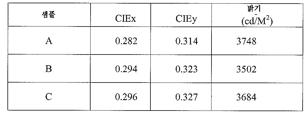
접차제 용액 A 900 g을 2000 ml 비이커에 넣고 자석에 의해 10분간 교반하였다. 이어, 인 분말 900 g을 부가하고, 그 혼합물을 기계적 임펠러(impeller)에 의해 실온에서 20분간 교반하여 균일하게 혼합된 슬러리를 얻었다. 일단 균일하게 혼합되면, 상기 슬러리는 슬럿 코팅법에 의해 PET 기판(125 ㎛ 두께)에 코팅되기 전에 30분간 교반하면서 공기 압력형 펄싱 순환기(pulsing circulator)에 넣었다. 슬럿 코팅하는 동안, 코팅압력 0.12 MPa 및 속도 15 cm/분으로 하고 코팅 슬럿을 PET 기판으로부터 15 ㎛ 간격을 두어 필름을 코팅하였다. 생성한 습윤 필름은 50℃에서 열풍(hot air) 건조시켜 PET 기판 상의 파장 변환 코팅의 두께가 12 내지 15㎛인 샘플을 얻었다. 900 g of the contact solution solution A was put into a 2000 ml beaker, and it stirred with a magnet for 10 minutes. Subsequently, 900 g of phosphorus powder was added, and the mixture was stirred for 20 minutes at room temperature by a mechanical impeller to obtain a uniformly mixed slurry. Once uniformly mixed, the slurry was placed in an air pressure pulsing circulator with stirring for 30 minutes before being coated onto the PET substrate (125 μm thick) by slot coating. During slot coating, the film was coated with a coating pressure of 0.12 MPa and a speed of 15 cm / min and coating slots spaced 15 μm from the PET substrate. The resulting wet film was hot air dried at 50 ° C. to obtain a sample having a thickness of 12 to 15 μm of the wavelength conversion coating on the PET substrate.
밝기 시험법 I을 채용하며, 샘플을 배치하는 영역은 길이 30 cm 및 폭 20 cm로 하며 샘플은 광원으로부터 1.5 cm 떨어지게 배치하였다. x 좌표, y 좌표 및 밝기 값은 CIE 1931에 기재된 색좌표 측정법에 따라 샘플 상에서 측정하였다. 결과를 하기 표 1에 수록하였다. Brightness test method I was employed, and the area where the sample was placed was 30 cm long and 20 cm wide, and the sample was placed 1.5 cm away from the light source. The x, y and brightness values were measured on the samples according to the color coordinate measurement method described in CIE 1931. The results are listed in Table 1 below.
표 1Table 1
파장 변환의 결과는 도 13a 및 도 13b에 도시하며, 이때 도 13a는 UVc 광원을 포함하는 모듈의 원래 광 스펙트럼을 도시하고, 도 13b는 생성한 샘플을 통하여 방출된 스펙트럼을 도시한다. 이들 결과는 파장 변환 코팅의 샘플은 UVc 광을 가시광으로 효과적으로 변환할 수 있음을 보여준다. The results of the wavelength conversion are shown in FIGS. 13A and 13B, where FIG. 13A shows the original light spectrum of the module including the UV c light source and FIG. 13B shows the spectrum emitted through the generated sample. These results show that samples of wavelength converting coatings can effectively convert UV c light into visible light.
실시예Example 2 2
슬러리를 125 ㎛ 두께의 PET 기판상에 코팅한 것을 제외하고는 실시예 1의 슬러리 제조, 코팅 및 건조 단계를 반복하여 PET 기판 상에 12 내지 15 ㎛ 두께의 파장 변환 코팅을 갖는 샘플을 수득하였다. The slurry preparation, coating and drying steps of Example 1 were repeated except that the slurry was coated on a 125 μm thick PET substrate to obtain a sample having a wavelength conversion coating of 12 to 15 μm thick on the PET substrate.
이어, 스크레이퍼(scraper)를 이용하여, 판테크 테이프 컴패니 리미티드(상품명 S3277)가 제조한 아크릴계 접착제를 샘플의 다른 면에 코팅하여 두께 25 ㎛를 달성하였다. 이어, 샘플에 아크릴계 기판(2 cm 두께) 및 PET 보호 기판(25㎛ 두께)과 함께 CSUN MFG 리미티드 (상품명 CSL-M25R)가 제조한 롤 적층기에 의해 적층하였다. 따라서, 샘플의 접착제 측은 아크릴계 기판의 한면에 적층된 반면에, PET 보호 기판은 아크릴계(폴리메틸 메타크릴레이트) 기판의 다른 면에 적층되었다. 적층 과정은 1.5 m/분의 속도, 3 kgf/cm2 압력으로 40℃에서 실시하였다. 유사하게, 아크릴계 기판 대신 폴리카보네이트 기판(2 cm 두께)을 사용하여 상술한 단계를 반복하였다. Subsequently, using a scraper, an acrylic adhesive prepared by Pantech Tape Company Limited (trade name S3277) was coated on the other side of the sample to achieve a thickness of 25 μm. The sample was then laminated with a roll laminator made by CSUN MFG Limited (trade name CSL-M25R) together with an acrylic substrate (2 cm thick) and a PET protective substrate (25 μm thick). Thus, the adhesive side of the sample was laminated to one side of the acrylic substrate, while the PET protective substrate was laminated to the other side of the acrylic (polymethyl methacrylate) substrate. The lamination process was carried out at 40 ° C. at a speed of 1.5 m / min, 3 kgf / cm 2 pressure. Similarly, the above steps were repeated using a polycarbonate substrate (2 cm thick) instead of an acrylic substrate.
밝기 시험법 I을 채용하며, 샘플을 배치하는 영역은 길이 30 cm 및 폭 20 cm로 하며 샘플은 광원으로부터 2 cm 떨어지게 배치하였다. x 좌표, y 좌표 및 밝기 값은 CIE 1931에 기재된 색좌표 측정법에 따라 샘플 상에서 측정하였다. 결과를 하기 표 2에 수록하였다. Brightness test method I was employed, and the area where the sample was placed was 30 cm long and 20 cm wide, and the sample was placed 2 cm away from the light source. The x, y and brightness values were measured on the samples according to the color coordinate measurement method described in CIE 1931. The results are listed in Table 2 below.
표 2TABLE 2
실시예Example 3 3
측량된 분말 및 측량된 접착제 용액을 하기 표 3에 수록된 중량비로 혼합물 로 제제화하였다. 이 혼합물을 6개의 50 ml 밀폐 바이얼에 각각 넣어 자석으로 10분간 교반시킨 다음 10분간 초음파 진동으로 교반하여 6개의 슬러리를 얻었다. The weighed powder and the weighed adhesive solution were formulated into the mixture in the weight ratios listed in Table 3 below. The mixture was placed in six 50 ml sealed vials, each stirred for 10 minutes with a magnet and then stirred for 10 minutes by ultrasonic vibration to obtain six slurries.
10 cm 폭 및 15 cm 길이의 PET 기판(125 ㎛ 두께)을 진공 흡착 테이블에 흡착시키고 상기 슬러리 중의 하나로 마이어 봉 코팅법에 의해 코팅 속도 10 m/분으로 코팅하였다. 이러한 코팅법을 6개 슬러리에 대해 반복하여 각 슬러리가 코팅된 6개의 PET 기판을 얻고, 이것을 공기 순환을 통한 자연 건조법에 3분간 처리하여 약 15 내지 18 ㎛ 두께의 코팅을 얻었다. A 10 cm wide and 15 cm long PET substrate (125 μm thick) was adsorbed onto a vacuum adsorption table and coated with one of the slurries at a coating rate of 10 m / min by Meyer rod coating. This coating method was repeated for six slurries to obtain six PET substrates coated with each slurry, which was treated for 3 minutes in a natural drying method through air circulation to obtain a coating having a thickness of about 15 to 18 μm.
밝기 시험법 I을 채용하며, 샘플을 배치하는 영역은 길이 30 cm 및 폭 20 cm로 하며 샘플은 광원으로부터 2 cm 떨어지게 배치하였다. x 좌표, y 좌표 및 밝기 값은 CIE 1931에 기재된 색좌표 측정법에 따라 샘플 상에서 측정하였다. 결과를 하기 표 3에 수록하였다. Brightness test method I was employed, and the area where the sample was placed was 30 cm long and 20 cm wide, and the sample was placed 2 cm away from the light source. The x, y and brightness values were measured on the samples according to the color coordinate measurement method described in CIE 1931. The results are listed in Table 3 below.
표 3TABLE 3

실시예Example 4 4
I. 탄소-플루오르 결합을 함유하는 접착제I. Adhesives Containing Carbon-Fluorine Bonds
접착제 용액 A, 접착제 용액 B 및 접착제 용액 C를 이 실시예에 사용하고, 각 접착제 용액에 함유된 인 분말 대 개별 접착제의 중량비가 5:1 이 되도록 한 이외에는 실시예 3의 슬러리 제조, 코팅 및 건조 단계를 반복하였다. 생성한 슬러리를 125 ㎛ 두께의 각 PET 기판에 코팅하여 12 내지 15 ㎛ 두께의 코팅을 갖는 샘플을 얻었다. 여기서, 접착제 용액 A, B 및 C로부터 제조한 샘플을 샘플 A, B 및 C라 각각 칭하였다. The slurry preparation, coating and drying of Example 3 was used except that adhesive solution A, adhesive solution B and adhesive solution C were used in this example and the weight ratio of phosphorus powder to individual adhesive contained in each adhesive solution was 5: 1. The step was repeated. The resulting slurry was coated onto each 125 μm thick PET substrate to obtain a sample having a coating of 12 to 15 μm thick. Here, the samples prepared from the adhesive solutions A, B and C were called Samples A, B and C, respectively.
밝기 시험법 I을 채용하며, 샘플을 배치하는 영역은 길이 10 cm 및 폭 10 cm로 하며 샘플은 광원으로부터 2 cm 떨어지게 배치하였다. x 좌표, y 좌표 및 밝기 값은 CIE 1931에 기재된 색좌표 측정법에 따라 샘플 상에서 측정하였다. 결과를 하기 표 4-1에 수록하였다. Brightness test method I was employed, and the area where the sample was placed was 10 cm long and 10 cm wide, and the sample was placed 2 cm away from the light source. The x, y and brightness values were measured on the samples according to the color coordinate measurement method described in CIE 1931. The results are listed in Table 4-1.
표 4-1Table 4-1
또한, 샘플 A 및 샘플 C는 다음 방식으로 가속(accelerated) 시험 처리하였다. 샘플 A 및 샘플 C를 단일 UV 램프 위로 광원으로부터 0.5 cm 떨어지게 놓았다. 각 샘플 상의 2 cm x 2 cm 영역에 UV광을 10000 μW/cm2 세기로 조명하였다. 샘플 상에서 세기 및 색값(chromatic value)을 시험 개시 직후 및 1000 시간 후에 측정하였다. 결과를 하기 표에 수록하였다. Sample A and Sample C were also accelerated tested in the following manner. Sample A and Sample C were placed 0.5 cm away from the light source over a single UV lamp. UV light was illuminated at 10000 μW / cm 2 intensity in a 2 cm × 2 cm area on each sample. Intensities and chromatic values on the samples were measured immediately after the start of the test and after 1000 hours. The results are listed in the table below.

IIII . 탄화수소계 접착제 (. Hydrocarbon-based adhesives ( 비교예Comparative example ))
5:1의 중량비로 인 분말과 접착제 용액 A를 취하여 50 ml 밀봉 바이얼에 넣고 자석에 의해 10분간, 이어 초음파 진동에 의해 10분간 더 교반하여 플루오로 슬러리를 얻었다. 또한 폴리비닐 알코올(PVA) 접착제 용액(탈이온수를 용매로 사용하고 20중량% PVA 함유)을 제조하고 동일 중량의 인 분말과 함께 모르타르에 의해 균일하게 혼합하여 탄화수소 결합 에너지 98 kcal/몰의 탄화수소계 슬러리를 얻었다. Phosphorus powder and adhesive solution A were taken in a weight ratio of 5: 1, and placed in a 50 ml sealed vial, which was further stirred for 10 minutes by magnet followed by ultrasonic vibration for 10 minutes to obtain a fluoro slurry. In addition, a polyvinyl alcohol (PVA) adhesive solution (using deionized water as a solvent and containing 20% by weight of PVA) was prepared and uniformly mixed with mortar with the same weight of phosphorus powder to obtain a hydrocarbon-based energy of 98 kcal / mole. A slurry was obtained.
폭 10 cm 및 길이 15cm 크기의 2개의 PET 기판(125 ㎛ 두께)을 진공 흡착 테이블 상에 흡착시키고 스크레이퍼 클리어런스(scraper clearance) 50 ㎛ 및 코팅 속도 10 m/분으로 상기 슬러리로 코팅하였다. 이어, 플루오로 슬러리로 코팅된 PET 기판은 공기 순환을 통한 자연 건조법에 3분간 처리하는 반면에, 탄화수소계 슬러리가 코팅된 PET 기판은 오븐에서 80℃ 열풍에 의해 30분간 가열하였다. 얻어진 코팅은 약 17 내지 20 ㎛ 두께를 가졌다. Two PET substrates (125 μm thick) 10 cm wide and 15 cm long were adsorbed onto a vacuum adsorption table and coated with the slurry with a scraper clearance of 50 μm and a coating rate of 10 m / min. Subsequently, the PET substrate coated with the fluoro slurry was treated for 3 minutes in a natural drying method through air circulation, while the PET substrate coated with the hydrocarbon slurry was heated for 30 minutes by an 80 ° C. hot air in an oven. The resulting coating had a thickness of about 17-20 μm.
밝기 시험법 I을 채용하며, 샘플을 배치하는 영역은 길이 30 cm 및 폭 20 cm 로 하며 샘플은 광원으로부터 1.5 cm 떨어지게 배치하였다. x 좌표, y 좌표 및 밝기 값은 CIE 1931에 기재된 색좌표 측정법에 따라 샘플 상에서 측정하였다. 결과를 하기 표 4-2에 수록하였다. Brightness test method I was employed, and the area where the sample was placed was 30 cm long and 20 cm wide and the sample was placed 1.5 cm away from the light source. The x, y and brightness values were measured on the samples according to the color coordinate measurement method described in CIE 1931. The results are listed in Table 4-2 below.
표 4-2Table 4-2

상기 표의 결과는 탄화수소계 슬러리의 거의 50% 밝기 감소와 비교하여, 본 발명에서의 탄소-플루오르 결합을 함유하는 접착제 용액으로 제조한 파장 변환 코팅은 180시간 동안 조명된 후에도 처음 값과 필적하는 밝기를 제공할 수 있음을 보여준다. The results in the table above show that the wavelength conversion coatings prepared with the adhesive solution containing carbon-fluorine bonds in the present invention have comparable brightness to the initial values even after being illuminated for 180 hours, compared to a nearly 50% decrease in brightness of the hydrocarbon based slurry. Show that you can provide.
IIIIII . 다른 접착제 용액. Other adhesive solutions
테트라에톡시실란(TEOS) 10g을 취하고 여기에 메틸트리에톡시실란(MTEOS) 10 g, 에탄올 3g, 탈이온수 2 g 및 1% HCl 수용액 1 ml를 부가하였다. 이어, 생성한 혼합물을 실온에서 30분간 교반하여 균일상을 얻었다. 이어, 인 분말 8g이 부가된 무기 수용액을 자석으로 60분간 교반한 다음 초음파 진동에 의해 10분간 교반하고, 또 이어 자석에 의해 30분 더 교반하여 슬러리를 얻었다. 10 g of tetraethoxysilane (TEOS) was taken and 10 g of methyltriethoxysilane (MTEOS), 3 g of ethanol, 2 g of deionized water and 1 ml of an aqueous 1% HCl solution were added. Then, the resulting mixture was stirred at room temperature for 30 minutes to obtain a homogeneous phase. Subsequently, the inorganic aqueous solution to which 8 g of phosphorus powder was added was stirred for 60 minutes with a magnet, then stirred for 10 minutes by ultrasonic vibration, and further stirred for 30 minutes with a magnet to obtain a slurry.
II에 기재된 것과 동일한 방식으로, 슬러리를 100 ㎛ 두께의 PET 기판에 코팅하였다. 코팅된 PET 기판을 100℃의 오븐에서 60분간 건조시킨 다음 꺼내기 까지 냉각시켰다. In the same manner as described in II, the slurry was coated on a 100 μm thick PET substrate. The coated PET substrate was dried in an oven at 100 ° C. for 60 minutes and then cooled to take out.
밝기 시험법 I을 채용하며, 샘플을 배치하는 영역은 5 cm 직경(즉, 19.6 cm2)이었고 또 샘플은 광원으로부터 2 cm 떨어지게 배치하였다. x 좌표, y 좌표 및 밝기 값은 CIE 1931에 기재된 색좌표 측정법에 따라 샘플 상에서 측정하였다. 결과를 하기 표 4-3에 수록하였다. Employing brightness test method I, the area in which the sample was placed was 5 cm in diameter (ie, 19.6 cm 2 ) and the sample was placed 2 cm away from the light source. The x, y and brightness values were measured on the samples according to the color coordinate measurement method described in CIE 1931. The results are listed in Table 4-3 below.
표 4-3Table 4-3

실시예Example 5 5
밝기 시험법 II를 채용하여 실시예 2의 아크릴계 기판으로 제조한 샘플의 성능과 통상의 CCFL이 성능을 동일 램프 전압, 전류 및 동일 측정 방법으로 비교하였다. 비교 결과를 하기 표 5-1 및 5-2에 수록한다. The performance of the sample prepared with the acrylic substrate of Example 2 using the brightness test method II and the performance of the conventional CCFL were compared by the same lamp voltage, current and the same measuring method. The comparison results are listed in Tables 5-1 and 5-2.
표 5-1Table 5-1

표 5-2Table 5-2

상기 결과는 본 발명의 파장 변환 코팅의 성능이 통상의 CCFL의 성능보다 더 우수하다는 것을 보여준다. The results show that the performance of the wavelength conversion coating of the present invention is better than that of conventional CCFLs.
밝기 시험법 II를 채용하며, 이때 아크릴계 기판 샘플(즉, 표 5-2 중에 수록된 "변환 코팅 + 하부 디퓨저" 항목에 상응)은 UVc 모듈에 장시간 동안 조사(조명)되었다. 색 좌표 및 밝기의 변화는 하기 표 6 및 도 14에 나타내었다. 이 시험에서, 각 조명 지속시간 값 동안, 동일한 아크릴계 기판 샘플 2개 세트 상에서 2개 시험을 실시하였다. 이 시험 결과는 표 6의 샘플 A 항목 및 샘플 B 항목에 수록하였다. 이들 결과는 장시간 동안의 조사(조명) 지속 후에도, 본 발명의 파장 변환 코팅은 여전히 뚜렷한 밝기를 제공할 수 있음을 나타낸다. Brightness test method II was employed, wherein an acrylic substrate sample (ie, corresponding to the "Conversion Coating + Lower Diffuser" item listed in Table 5-2) was irradiated (lighted) to the UV c module for a long time. Changes in color coordinates and brightness are shown in Table 6 and FIG. 14. In this test, two tests were run on two sets of identical acrylic substrate samples for each illumination duration value. The test results are listed in Sample A and Sample B in Table 6. These results indicate that even after prolonged irradiation (lighting) duration, the wavelength converting coating of the present invention can still provide distinct brightness.
표 6Table 6

실시예Example 6 ( 6 ( UVUV 차단 코팅의 효과) Effect of barrier coating)
접착제 용액 A 20 g 및 인 분말 20 g을 50 ml의 밀봉 바이얼에 넣고 자석에 의해 10분간, 이어 초음파 진동에 의해 10분 더 교반하였다. 생성한 슬러리를 스크레이퍼 클리어런스 50 ㎛ 및 코팅 속도 10m/분으로 석영 조각(10 cm x 10 cm)의 표면상에 코팅하였다. 이어, 코팅된 석영을 공기 순환을 통하여 자연 건조법에 3분간 처리하여 약 17 내지 20 ㎛ 두께의 코팅을 얻었다. 이렇게하여, UV 차단 코팅을 갖지 않는 파장 변환 코팅 샘플을 제공하였다. 20 g of adhesive solution A and 20 g of phosphorus powder were placed in a 50 ml sealing vial and stirred for 10 minutes by magnet followed by 10 minutes by ultrasonic vibration. The resulting slurry was coated on the surface of a piece of quartz (10 cm x 10 cm) with a scraper clearance of 50 μm and a coating speed of 10 m / min. Subsequently, the coated quartz was treated for 3 minutes in a natural drying method through air circulation to obtain a coating having a thickness of about 17 to 20 μm. This gave a wavelength converting coating sample without a UV blocking coating.
다른 파장 변환 코팅 샘플은 석영 조각 표면에 UV 차단성 나노크기의 산화아연(상품명 NanoZ, 어드밴스트 나노테크놀로지, 오스트랠리아 제조) 층을 마이어 봉 코팅법(RDS 번호 06)에 의해 코팅 속도 10m/분으로 미리 코팅한 것을 제외하고는 실질적으로 동일한 방식으로 제조하였다. 코팅된 석영을 오븐에 넣고 100℃ 열풍에 30분간 두었다. Another wavelength converting coating sample was coated with a layer of UV-blocking zinc oxide (trade name NanoZ, Advanced Nanotechnology, Australia) on the surface of the quartz piece by a Meyer rod coating method (RDS No. 06) for 10 m / min. It was prepared in substantially the same manner except that it was precoated with. The coated quartz was placed in an oven and placed in a 100 ° C. hot air for 30 minutes.
밝기 시험법 I을 채용하며, 샘플을 배치하는 영역은 길이 30 cm 및 폭 20 cm로 하며 샘플은 광원으로부터 2 cm 떨어지게 배치하였다. x 좌표, y 좌표 및 밝기 값은 CIE 1931에 기재된 색좌표 측정법에 따라 샘플 상에서 측정하였다. 결과를 하기 표 6 및 도 15a (UV 차단 코팅 없음) 및 도 15b (UV 차단 코팅 가짐)에 수록하였다.Brightness test method I was employed, and the area where the sample was placed was 30 cm long and 20 cm wide, and the sample was placed 2 cm away from the light source. The x, y and brightness values were measured on the samples according to the color coordinate measurement method described in CIE 1931. The results are listed in Table 6 below and in FIG. 15A (without UV barrier coating) and FIG. 15B (with UV barrier coating).
표 7TABLE 7

도 15a 및 도 15b를 비교함으로써, UV 차단 코팅을 갖지 않는 발광 모듈의 경우에서 사용한 UVc 스펙트럼 밴드 및 사용하지 않은 UVA 및 UVB 스펙트럼 밴드의 약간의 누출이 여전히 밝혀졌다. 이와 대조적으로, UV 차단 코팅이 사용될 때, UVc 스펙트럼 밴드 및 UVA 및 UVB 스펙트럼 밴드는 모두 효과적으로 차단되었다. 또한, 표 7로부터, UV 차단 코팅의 사용은 발광 모듈의 성능에 아무런 영향을 가지지 않음을 알 수 있다. By comparing FIGS. 15A and 15B, slight leakage of the used UV c spectral band and the unused UV A and UV B spectral bands was still found in the case of the light emitting module without UV blocking coating. In contrast, when the UV blocking coating was used, both the UV c spectral band and the UV A and UV B spectral bands were effectively blocked. In addition, from Table 7, it can be seen that the use of the UV blocking coating has no effect on the performance of the light emitting module.
실시예Example 7 ( 7 ( UVUV 차단 코팅의 효과) Effect of barrier coating)
이 실시예는 PET (폴리에틸렌 테레프탈레이트) 기판을 사용하고 또 UV 광 투과율을 도 16a 및 도 16b에 도시한 바와 같이 측정한 것을 제외하고는 실시예 6과 동일하였다. 도 16a는 UV 차단 코팅을 갖지 않는 발광 모듈의 UV 광 투과 스펙트럼을 도시하고, 또 도 16b는 UV 차단 코팅을 갖는 발광 모듈의 UV 광 투과 스펙트럼을 도시하며, 파선으로 표시된 부분은 UVc 스펙트럼 밴드 및 UVB 스펙트럼 밴드를 각각 나타낸다. 도 16a 및 도 16b를 비교함으로써 UV 광 누출은 UV 차단 코팅이 사용되면 거의 완전하게 차단될 수 있음을 알 수 있다. This example was the same as Example 6 except that a PET (polyethylene terephthalate) substrate was used and UV light transmittance was measured as shown in Figs. 16A and 16B. FIG. 16A shows the UV light transmission spectrum of the light emitting module without the UV blocking coating, and FIG. 16B shows the UV light transmission spectrum of the light emitting module with the UV blocking coating, and the portions indicated by the broken lines are the UV c spectral band and UV B spectral bands are respectively shown. Comparing FIGS. 16A and 16B it can be seen that UV light leakage can be almost completely blocked if a UV blocking coating is used.
실시예Example 8 (광 혼합의 효과) 8 (Effect of Light Mixing)
도 3a에 도시한 구조 2개 세트를 제공하였고, 이때 제1 세트의 제1 및 제2 파장 변환 코팅은 동일하였고, 또 제2 세트의 제1 및 제2 파장 변환 코팅은 상이하였다. 접착제 용액 A 및 카세이 컴패니 리미티드 재팬이 제조한 인 분말을 사용하였다. Two sets of structures shown in FIG. 3A were provided, wherein the first set of first and second wavelength converting coatings were the same and the second set of first and second wavelength converting coatings were different. Phosphorus powder prepared by Adhesive Solution A and Kasei Company Limited Japan was used.
제1 세트의 제1 및 제2 파장 변환 코팅은 다음과 같은 방식으로 제조하였다. UVc 선에 의해 여기될 때 적색 가시광을 방출할 수 있었던 인 분말("R 인 분말"), UVc 선에 의해 여기될 때 녹색 가시광을 방출할 수 있었던 인 분말("G 인 분말") 및 UVc 선에 의해 여기될 때 청색 가시광을 방출할 수 있었던 인 분말("B 인 분말")을 4.4:1.6:4.0 비율로 혼합하여 인 분말 혼합물을 얻었다. 생성한 혼합물을 50 ml 밀봉 바이얼에 함유된 접착제 용액 A 10 g에 붓고, 자석에 의해 10분간, 이어 초음파 진동에 의해 10분간 더 교반하여 슬러리를 얻었다. PET 기판(100㎛ 두께; 10 cm x 15 cm)를 진공 흡착 테이블 상에 흡착시키고 스크레이퍼 코팅법을 이용하여 슬러리를 코팅하였다. 상기 코팅법은 스크레이퍼 클리어런스 50㎛ 및 코팅 속도 10 m/분으로 실시하였다. 그후, 코팅된 PET 기판을 공기 순환을 통하여 자연 건조법에 3분간 처리하여 약 17 내지 20㎛ 두께의 코팅을 얻었다. The first set of first and second wavelength converting coatings were prepared in the following manner. Phosphorous powder that could emit red visible light when excited by UV c- rays (“R Phosphorus Powder”), phosphorous powder that could emit green visible light when excited by UV c- rays (“G Phosphorus Powder”), and Phosphorus powder (“B phosphorus powder”), which could emit blue visible light when excited by UV c- rays, was mixed in a 4.4: 1.6: 4.0 ratio to obtain a phosphorus powder mixture. The resulting mixture was poured into 10 g of the adhesive solution A contained in a 50 ml sealed vial, and further stirred for 10 minutes by magnet followed by 10 minutes by ultrasonic vibration to obtain a slurry. PET substrates (100 μm thick; 10 cm × 15 cm) were adsorbed onto a vacuum adsorption table and the slurry was coated using scraper coating. The coating method was performed at a scraper clearance of 50 μm and a coating speed of 10 m / min. Thereafter, the coated PET substrate was treated for 3 minutes in a natural drying method through air circulation to obtain a coating having a thickness of about 17 to 20 μm.
제2 세트의 제1 파장 변환 코팅은, R 인 분말 및 G 인 분말을 4.9: 1.5 비율로 혼합하여 인 분말 혼합물 6.4 g을 제조한 다음 접착제 용액 A 6.4 g에 넣어 슬러리를 제조한 이외에는, 제1 세트와 동일한 방식으로 제2 세트의 제1 파장 변환 코팅을 제조하였다. The second set of first wavelength converting coatings was prepared by mixing the phosphorus R powder and the phosphorus G powder in a 4.9: 1.5 ratio to produce 6.4 g of a phosphorus powder mixture and then placing it in 6.4 g of adhesive solution A to produce a slurry. A second set of first wavelength converting coatings was prepared in the same manner as the set.
제2 세트의 제2 파장 변환 코팅은, B 인 분말 10g을 접착제 용액 A 10 g과 혼합한 다음 두께 225 ㎛의 PET 기판에 코팅한 것을 제외하고는, 제1 세트와 동일한 방식으로 제조하였다. A second set of second wavelength converting coatings was prepared in the same manner as the first set, except that 10 g of powder B was mixed with 10 g of adhesive solution A and then coated onto a PET substrate having a thickness of 225 μm.
제1 파장 변환 코팅을 갖는 PET 기판 2개 세트를 프레임 바디의 양쪽 세트의 개구 위로 배치시키는 한편, 제2 파장 변환 코팅을 갖는 PET 기판은 프레임 바디의 내벽 상에 배치시켰다. 이어, 구조의 2개 세트의 광학 특징을 측정하고, 그 결과를 하기 표 8에 수록하였다. Two sets of PET substrates with a first wavelength converting coating were placed over both sets of openings in the frame body, while a PET substrate with a second wavelength converting coating was placed on the inner wall of the frame body. The optical characteristics of the two sets of structures were then measured and the results are listed in Table 8 below.
표 8Table 8

표 8은 제2 세트에 의해 제공된 밝기가 제1 세트에 비하여 약 5% 내지 6% 증가됨을 나타낸다. Table 8 shows that the brightness provided by the second set is increased by about 5% to 6% relative to the first set.
상기 내용은 본 발명의 상세한 기술 내용 및 특징에 관련된 것이다. 당업자들은 본 발명의 특징에서 벗어남없이 상기 기재한 본 발명의 내용 및 제시를 기본으로 하여 다양한 변형과 치환을 실시할 수 있을 것이다. 이러한 변형 및 치환은 상기 기재에 충분히 기재되지 않았지만, 이들은 첨부한 특허청구범위에 실질적으로 포함되는 것이다. The foregoing is related to the detailed description and features of the present invention. Those skilled in the art will be able to make various modifications and substitutions based on the contents and presentation of the invention described above without departing from the features of the invention. Such modifications and substitutions are not fully described in the above description, but they are substantially included in the appended claims.
도 1a는 본 발명에 따른 파장 변환 구조의 구체예의 설명도이다. 1A is an explanatory view of a specific example of the wavelength conversion structure according to the present invention.
도 1b는 본 발명에 따른 파장 변환 구조의 다른 구체예의 설명도이며, 이 구조에 함유된 기판은 복합체층이다. 1B is an explanatory view of another embodiment of the wavelength conversion structure according to the present invention, wherein the substrate contained in the structure is a composite layer.
도 1c는 본 발명에 따른 파장 변환 구조의 다른 구체예의 설명도이며, 이 구조에 함유된 기판은 광학 강화층이다. 1C is an explanatory view of another embodiment of the wavelength conversion structure according to the present invention, wherein the substrate contained in the structure is an optical enhancement layer.
도 2a는 파장 변환 구조를 이용하는 발광 모듈을 도시한다. 2A shows a light emitting module using a wavelength conversion structure.
도 2b는 본 명세서에 기재된 발광 모듈의 프레임 바디에 사용될 수 있는 광원 홀더의 설명도이다. 2B is an explanatory view of a light source holder that can be used for the frame body of the light emitting module described herein.
도 3a 및 도 3b는 본 발명을 이용하는 발광 모듈의 광 혼합 구체예를 도시한다. 3A and 3B show light mixing embodiments of light emitting modules utilizing the present invention.
도 4a 내지 도 4c는 UV 차단 코팅을 포함하는 발광 모듈의 구체예를 도시한다. 4A-4C show an embodiment of a light emitting module comprising a UV blocking coating.
도 5는 발광 모듈의 프레임 바디의 내벽 상에 배치된 보호층의 설명도이다. 5 is an explanatory view of a protective layer disposed on an inner wall of a frame body of a light emitting module.
도 6은 파장 변환 구조를 이용하는 측면형 백라이트 모듈의 구체예의 설명도이다. 6 is an explanatory diagram of a specific example of a side type backlight module using the wavelength conversion structure.
도 7은 파장 변환 구조를 이용하는 직접형 백라이트 모듈의 구체예의 설명도이다. 7 is an explanatory diagram of a specific example of a direct backlight module using the wavelength conversion structure.
도 8은 통상의 직접형 백라이트 모듈의 설명도를 도시한다. 8 shows an explanatory diagram of a conventional direct backlight module.
도 9a 내지 도 12c는 다양한 고정 장치를 포함하는 백라이트 모듈의 구체예 의 설명도를 도시한다. 9A-12C show explanatory diagrams of embodiments of a backlight module including various fixing devices.
도 13a는 실시예 1의 UVc 모듈의 원래 광 스펙트럼을 도시한다.13A shows the original light spectrum of the UV c module of Example 1. FIG.
도 13b는 본 발명의 파장 변환 구조를 통하여 방출된 도 13a에 도시된 UVc 모듈의 광 스펙트럼을 도시한다. FIG. 13B shows the light spectrum of the UV c module shown in FIG. 13A emitted through the wavelength conversion structure of the present invention.
도 14는 UVc 에 의해 3400 시간 동안 조사된 실시예 2로부터 얻은 샘플 상에서 측정된 색 좌표 및 밝기의 변화를 도시한다. FIG. 14 shows changes in color coordinates and brightness measured on samples obtained from Example 2 irradiated for 3400 hours by UV c .
도 15a는 실시예 6으로부터 얻은 UV 차단 코팅을 갖지 않는 구체예의 광 스펙트럼을 도시한다. 15A shows the light spectrum of an embodiment without the UV blocking coating obtained from Example 6. FIG.
도 15b는 실시예 6으로부터 얻은 UV 차단 코팅을 갖는 구체예의 광 스펙트럼을 도시한다. 15B shows the light spectrum of an embodiment with a UV blocking coating obtained from Example 6. FIG.
도 16a는 실시예 7로부터 얻은 UV 차단 코팅을 갖지 않는 구체예의 광 스펙트럼을 도시한다. 16A shows the light spectrum of an embodiment without the UV blocking coating obtained from Example 7. FIG.
도 16b는 실시예 7로부터 얻은 UV 차단 코팅을 갖는 구체예의 광 스펙트럼을 도시한다. 16B shows the light spectrum of an embodiment with a UV blocking coating obtained from Example 7. FIG.
Claims (58)
Applications Claiming Priority (4)
| Application Number | Priority Date | Filing Date | Title |
|---|---|---|---|
| TW96102110 | 2007-01-19 | ||
| TW096102110 | 2007-01-19 | ||
| TW096127149 | 2007-07-25 | ||
| TW096127149A TW200831658A (en) | 2007-01-19 | 2007-07-25 | Wavelength converting structure and manufacture and use of the same |
Publications (1)
| Publication Number | Publication Date |
|---|---|
| KR20080068526A true KR20080068526A (en) | 2008-07-23 |
Family
ID=39535115
Family Applications (1)
| Application Number | Title | Priority Date | Filing Date |
|---|---|---|---|
| KR1020070120003A KR20080068526A (en) | 2007-01-19 | 2007-11-23 | Wavelength converting structure and manufacture and use of the same |
Country Status (5)
| Country | Link |
|---|---|
| US (1) | US20080176066A1 (en) |
| EP (1) | EP1947670A3 (en) |
| JP (1) | JP2008179781A (en) |
| KR (1) | KR20080068526A (en) |
| TW (1) | TW200831658A (en) |
Cited By (2)
| Publication number | Priority date | Publication date | Assignee | Title |
|---|---|---|---|---|
| KR101326905B1 (en) * | 2011-12-01 | 2013-11-11 | 엘지이노텍 주식회사 | Optical member and display device having the same |
| WO2014148792A1 (en) * | 2013-03-18 | 2014-09-25 | 고려대학교 산학협력단 | Color conversion film comprising inorganic coating layer and polymer coating layer, and method for manufacturing same |
Families Citing this family (25)
| Publication number | Priority date | Publication date | Assignee | Title |
|---|---|---|---|---|
| US20090194774A1 (en) * | 2008-02-04 | 2009-08-06 | Kismart Corporation | Light source module with wavelength converting structure and the method of forming the same |
| WO2009107535A1 (en) * | 2008-02-25 | 2009-09-03 | 株式会社東芝 | White led lamp, backlight, light emitting device, display device and lighting device |
| JP2011513928A (en) * | 2008-03-07 | 2011-04-28 | コーニンクレッカ フィリップス エレクトロニクス エヌ ヴィ | Optical system with removable light extraction member |
| US8081289B2 (en) * | 2008-08-06 | 2011-12-20 | Universal Optoelectronics Co., Ltd. | Enhanced wavelength-converting structure |
| KR20110057239A (en) | 2008-09-16 | 2011-05-31 | 코닌클리즈케 필립스 일렉트로닉스 엔.브이. | Polymeric wavelength converting elements |
| WO2011016282A1 (en) * | 2009-08-05 | 2011-02-10 | コニカミノルタオプト株式会社 | Light emitting device and method for manufacturing light emitting device |
| EP2555260A1 (en) | 2010-03-30 | 2013-02-06 | Mitsubishi Chemical Corporation | Light-emitting device |
| TWI476959B (en) * | 2010-04-11 | 2015-03-11 | Achrolux Inc | Method for transferring a uniform phosphor layer on an article and light-emitting structure fabricated by the method |
| TWI425259B (en) * | 2010-04-23 | 2014-02-01 | Benq Materials Corp | A polarizer structure and a liquid crystal module using the polarizer structure |
| EP2583306A4 (en) * | 2010-06-17 | 2014-09-17 | Achrolux Inc | Light-emitting structure and a method for fabricating the same |
| US8297767B2 (en) | 2010-09-07 | 2012-10-30 | Xicato, Inc. | LED-based illumination modules with PTFE color converting surfaces |
| US8493569B2 (en) * | 2010-12-27 | 2013-07-23 | Mitutoyo Corporation | Optical encoder readhead configuration with phosphor layer |
| US8425065B2 (en) * | 2010-12-30 | 2013-04-23 | Xicato, Inc. | LED-based illumination modules with thin color converting layers |
| KR101210163B1 (en) * | 2011-04-05 | 2012-12-07 | 엘지이노텍 주식회사 | Optical sheet and method of fabricating the same |
| JP5373859B2 (en) * | 2011-07-05 | 2013-12-18 | デクセリアルズ株式会社 | Lighting device |
| CN104011585A (en) * | 2011-09-30 | 2014-08-27 | 皇家飞利浦有限公司 | Display backlight system |
| JP6134176B2 (en) * | 2013-03-22 | 2017-05-24 | スタンレー電気株式会社 | Light emitting device and manufacturing method thereof |
| JP2015038960A (en) * | 2013-05-16 | 2015-02-26 | 株式会社日本セラテック | Light emitting device |
| US20160190406A1 (en) * | 2014-12-24 | 2016-06-30 | Epistar Corporation | Light-emitting device and manufacturing method thereof |
| JP6829969B2 (en) * | 2015-09-28 | 2021-02-17 | 日東電工株式会社 | An optical member, a set of polarizing plates using the optical member, and a liquid crystal display device. |
| JP6288061B2 (en) * | 2015-12-10 | 2018-03-07 | 日亜化学工業株式会社 | Method for manufacturing light emitting device |
| US11047747B2 (en) | 2017-03-27 | 2021-06-29 | Firouzeh Sabri | Light weight flexible temperature sensor kit |
| CN109696792B (en) * | 2017-10-24 | 2022-03-29 | 中强光电股份有限公司 | Projector and wavelength conversion device |
| JP6508368B2 (en) * | 2018-02-07 | 2019-05-08 | 日亜化学工業株式会社 | Light emitting device |
| CN110456555B (en) * | 2019-08-27 | 2022-03-15 | 昆山工研院新型平板显示技术中心有限公司 | Color filter and preparation method thereof |
Family Cites Families (5)
| Publication number | Priority date | Publication date | Assignee | Title |
|---|---|---|---|---|
| IL116092A (en) * | 1994-11-30 | 2000-06-29 | Honeywell Inc | Ultraviolet transparent binder for phosphor fluorescent light box |
| JP2000212554A (en) * | 1998-11-20 | 2000-08-02 | Idemitsu Kosan Co Ltd | Fluorescence conversion medium and display device using the same |
| DE19946125C1 (en) * | 1999-09-20 | 2001-01-04 | Plasma Photonics Gmbh | Phosphor film, especially for low pressure discharge lamp useful e.g. for therapeutic and/or cosmetic treatment, consists of silicone elastomer with embedded phosphor particles |
| US6402987B1 (en) | 1999-12-01 | 2002-06-11 | General Electric Company | YMO4:Eu,L phoshpor with improved lumen maintenance |
| CN101851432B (en) * | 2005-06-14 | 2012-10-17 | 电气化学工业株式会社 | Resin composition and sheet containing phosphor, and light emitting element using such composition and sheet |
-
2007
- 2007-07-25 TW TW096127149A patent/TW200831658A/en unknown
- 2007-11-15 US US11/940,845 patent/US20080176066A1/en not_active Abandoned
- 2007-11-23 KR KR1020070120003A patent/KR20080068526A/en not_active Application Discontinuation
- 2007-12-13 JP JP2007321891A patent/JP2008179781A/en active Pending
-
2008
- 2008-01-02 EP EP08100025A patent/EP1947670A3/en not_active Withdrawn
Cited By (3)
| Publication number | Priority date | Publication date | Assignee | Title |
|---|---|---|---|---|
| KR101326905B1 (en) * | 2011-12-01 | 2013-11-11 | 엘지이노텍 주식회사 | Optical member and display device having the same |
| WO2014148792A1 (en) * | 2013-03-18 | 2014-09-25 | 고려대학교 산학협력단 | Color conversion film comprising inorganic coating layer and polymer coating layer, and method for manufacturing same |
| KR101459718B1 (en) * | 2013-03-18 | 2014-11-12 | 고려대학교 산학협력단 | Color change film containing inorganic coating layer and polymer coating layer, and method for manufacturing thereof |
Also Published As
| Publication number | Publication date |
|---|---|
| JP2008179781A (en) | 2008-08-07 |
| TW200831658A (en) | 2008-08-01 |
| EP1947670A3 (en) | 2009-09-30 |
| EP1947670A2 (en) | 2008-07-23 |
| US20080176066A1 (en) | 2008-07-24 |
Similar Documents
| Publication | Publication Date | Title |
|---|---|---|
| KR20080068526A (en) | Wavelength converting structure and manufacture and use of the same | |
| CN201185179Y (en) | Backlight module unit | |
| US20090194774A1 (en) | Light source module with wavelength converting structure and the method of forming the same | |
| US9850427B2 (en) | Phosphor sheet | |
| KR101604339B1 (en) | Light conversion film, baclight unit and display devive comprising the same | |
| KR102098682B1 (en) | Quantum dot films, lighting devices, and lighting methods | |
| US20160380170A1 (en) | White led, backlight module and liquid crystal display device | |
| TW201105767A (en) | A phosphor sheet, a diffusion plate, an illuminating device, and a display unit | |
| EP3620834A1 (en) | Light conversion film for use in backlight module, backlight module, and display device | |
| KR20160069393A (en) | Method for manufacturing light conversion composite, light conversion film, backlight unit and display device comprising the same | |
| CN204314577U (en) | Optical diaphragm group, backlight module and liquid crystal display module | |
| CN209858903U (en) | Composite optical film, backlight device and display device | |
| WO2017111099A1 (en) | Wavelength conversion film | |
| CN108321284B (en) | Direct type quantum dot white light LED backlight module and preparation method thereof | |
| US9722151B2 (en) | Quantum dots (QD) glass cells, and the manufacturing methods and applications thereof | |
| JP2016075838A (en) | Liquid crystal display device | |
| TWI493258B (en) | Liquid crystal display device with backlight | |
| TW200832495A (en) | Light module | |
| JP2015195397A (en) | Solar battery module | |
| CN106970488A (en) | A kind of optical film assembly, backlight module and display device | |
| Yang et al. | “Giant” quantum dots encapsulated inside a freeform lens | |
| TWM341811U (en) | Light source module with shared wavelength converting structure | |
| JP2016194561A (en) | Quantum dot sheet, backlight device, and display | |
| TWI500883B (en) | Reflective film for lighting fixtures | |
| KR20100112785A (en) | Transmitting-emissive display device |
Legal Events
| Date | Code | Title | Description |
|---|---|---|---|
| A201 | Request for examination | ||
| E902 | Notification of reason for refusal | ||
| E601 | Decision to refuse application |