KR20080022175A - Method of making a sliding bearing - Google Patents
Method of making a sliding bearing Download PDFInfo
- Publication number
- KR20080022175A KR20080022175A KR1020087000139A KR20087000139A KR20080022175A KR 20080022175 A KR20080022175 A KR 20080022175A KR 1020087000139 A KR1020087000139 A KR 1020087000139A KR 20087000139 A KR20087000139 A KR 20087000139A KR 20080022175 A KR20080022175 A KR 20080022175A
- Authority
- KR
- South Korea
- Prior art keywords
- bearing face
- bearing
- depositing
- cavity
- face
- Prior art date
Links
Images


Classifications
-
- B—PERFORMING OPERATIONS; TRANSPORTING
- B23—MACHINE TOOLS; METAL-WORKING NOT OTHERWISE PROVIDED FOR
- B23P—METAL-WORKING NOT OTHERWISE PROVIDED FOR; COMBINED OPERATIONS; UNIVERSAL MACHINE TOOLS
- B23P15/00—Making specific metal objects by operations not covered by a single other subclass or a group in this subclass
- B23P15/003—Making specific metal objects by operations not covered by a single other subclass or a group in this subclass bearings
-
- F—MECHANICAL ENGINEERING; LIGHTING; HEATING; WEAPONS; BLASTING
- F16—ENGINEERING ELEMENTS AND UNITS; GENERAL MEASURES FOR PRODUCING AND MAINTAINING EFFECTIVE FUNCTIONING OF MACHINES OR INSTALLATIONS; THERMAL INSULATION IN GENERAL
- F16C—SHAFTS; FLEXIBLE SHAFTS; ELEMENTS OR CRANKSHAFT MECHANISMS; ROTARY BODIES OTHER THAN GEARING ELEMENTS; BEARINGS
- F16C33/00—Parts of bearings; Special methods for making bearings or parts thereof
- F16C33/02—Parts of sliding-contact bearings
-
- B—PERFORMING OPERATIONS; TRANSPORTING
- B21—MECHANICAL METAL-WORKING WITHOUT ESSENTIALLY REMOVING MATERIAL; PUNCHING METAL
- B21D—WORKING OR PROCESSING OF SHEET METAL OR METAL TUBES, RODS OR PROFILES WITHOUT ESSENTIALLY REMOVING MATERIAL; PUNCHING METAL
- B21D53/00—Making other particular articles
- B21D53/10—Making other particular articles parts of bearings; sleeves; valve seats or the like
-
- F—MECHANICAL ENGINEERING; LIGHTING; HEATING; WEAPONS; BLASTING
- F16—ENGINEERING ELEMENTS AND UNITS; GENERAL MEASURES FOR PRODUCING AND MAINTAINING EFFECTIVE FUNCTIONING OF MACHINES OR INSTALLATIONS; THERMAL INSULATION IN GENERAL
- F16C—SHAFTS; FLEXIBLE SHAFTS; ELEMENTS OR CRANKSHAFT MECHANISMS; ROTARY BODIES OTHER THAN GEARING ELEMENTS; BEARINGS
- F16C17/00—Sliding-contact bearings for exclusively rotary movement
- F16C17/02—Sliding-contact bearings for exclusively rotary movement for radial load only
- F16C17/03—Sliding-contact bearings for exclusively rotary movement for radial load only with tiltably-supported segments, e.g. Michell bearings
- F16C17/035—Sliding-contact bearings for exclusively rotary movement for radial load only with tiltably-supported segments, e.g. Michell bearings the segments being integrally formed with, or rigidly fixed to, a support-element
-
- F—MECHANICAL ENGINEERING; LIGHTING; HEATING; WEAPONS; BLASTING
- F16—ENGINEERING ELEMENTS AND UNITS; GENERAL MEASURES FOR PRODUCING AND MAINTAINING EFFECTIVE FUNCTIONING OF MACHINES OR INSTALLATIONS; THERMAL INSULATION IN GENERAL
- F16C—SHAFTS; FLEXIBLE SHAFTS; ELEMENTS OR CRANKSHAFT MECHANISMS; ROTARY BODIES OTHER THAN GEARING ELEMENTS; BEARINGS
- F16C17/00—Sliding-contact bearings for exclusively rotary movement
- F16C17/04—Sliding-contact bearings for exclusively rotary movement for axial load only
- F16C17/06—Sliding-contact bearings for exclusively rotary movement for axial load only with tiltably-supported segments, e.g. Michell bearings
- F16C17/065—Sliding-contact bearings for exclusively rotary movement for axial load only with tiltably-supported segments, e.g. Michell bearings the segments being integrally formed with, or rigidly fixed to, a support-element
-
- F—MECHANICAL ENGINEERING; LIGHTING; HEATING; WEAPONS; BLASTING
- F16—ENGINEERING ELEMENTS AND UNITS; GENERAL MEASURES FOR PRODUCING AND MAINTAINING EFFECTIVE FUNCTIONING OF MACHINES OR INSTALLATIONS; THERMAL INSULATION IN GENERAL
- F16C—SHAFTS; FLEXIBLE SHAFTS; ELEMENTS OR CRANKSHAFT MECHANISMS; ROTARY BODIES OTHER THAN GEARING ELEMENTS; BEARINGS
- F16C33/00—Parts of bearings; Special methods for making bearings or parts thereof
- F16C33/02—Parts of sliding-contact bearings
- F16C33/04—Brasses; Bushes; Linings
- F16C33/06—Sliding surface mainly made of metal
- F16C33/10—Construction relative to lubrication
- F16C33/1025—Construction relative to lubrication with liquid, e.g. oil, as lubricant
- F16C33/103—Construction relative to lubrication with liquid, e.g. oil, as lubricant retained in or near the bearing
-
- F—MECHANICAL ENGINEERING; LIGHTING; HEATING; WEAPONS; BLASTING
- F16—ENGINEERING ELEMENTS AND UNITS; GENERAL MEASURES FOR PRODUCING AND MAINTAINING EFFECTIVE FUNCTIONING OF MACHINES OR INSTALLATIONS; THERMAL INSULATION IN GENERAL
- F16C—SHAFTS; FLEXIBLE SHAFTS; ELEMENTS OR CRANKSHAFT MECHANISMS; ROTARY BODIES OTHER THAN GEARING ELEMENTS; BEARINGS
- F16C33/00—Parts of bearings; Special methods for making bearings or parts thereof
- F16C33/02—Parts of sliding-contact bearings
- F16C33/04—Brasses; Bushes; Linings
- F16C33/06—Sliding surface mainly made of metal
- F16C33/10—Construction relative to lubrication
- F16C33/1025—Construction relative to lubrication with liquid, e.g. oil, as lubricant
- F16C33/106—Details of distribution or circulation inside the bearings, e.g. details of the bearing surfaces to affect flow or pressure of the liquid
- F16C33/1075—Wedges, e.g. ramps or lobes, for generating pressure
-
- F—MECHANICAL ENGINEERING; LIGHTING; HEATING; WEAPONS; BLASTING
- F16—ENGINEERING ELEMENTS AND UNITS; GENERAL MEASURES FOR PRODUCING AND MAINTAINING EFFECTIVE FUNCTIONING OF MACHINES OR INSTALLATIONS; THERMAL INSULATION IN GENERAL
- F16C—SHAFTS; FLEXIBLE SHAFTS; ELEMENTS OR CRANKSHAFT MECHANISMS; ROTARY BODIES OTHER THAN GEARING ELEMENTS; BEARINGS
- F16C33/00—Parts of bearings; Special methods for making bearings or parts thereof
- F16C33/02—Parts of sliding-contact bearings
- F16C33/04—Brasses; Bushes; Linings
- F16C33/26—Brasses; Bushes; Linings made from wire coils; made from a number of discs, rings, rods, or other members
-
- F—MECHANICAL ENGINEERING; LIGHTING; HEATING; WEAPONS; BLASTING
- F16—ENGINEERING ELEMENTS AND UNITS; GENERAL MEASURES FOR PRODUCING AND MAINTAINING EFFECTIVE FUNCTIONING OF MACHINES OR INSTALLATIONS; THERMAL INSULATION IN GENERAL
- F16C—SHAFTS; FLEXIBLE SHAFTS; ELEMENTS OR CRANKSHAFT MECHANISMS; ROTARY BODIES OTHER THAN GEARING ELEMENTS; BEARINGS
- F16C33/00—Parts of bearings; Special methods for making bearings or parts thereof
- F16C33/30—Parts of ball or roller bearings
- F16C33/58—Raceways; Race rings
- F16C33/62—Selection of substances
-
- F—MECHANICAL ENGINEERING; LIGHTING; HEATING; WEAPONS; BLASTING
- F02—COMBUSTION ENGINES; HOT-GAS OR COMBUSTION-PRODUCT ENGINE PLANTS
- F02F—CYLINDERS, PISTONS OR CASINGS, FOR COMBUSTION ENGINES; ARRANGEMENTS OF SEALINGS IN COMBUSTION ENGINES
- F02F1/00—Cylinders; Cylinder heads
- F02F1/18—Other cylinders
- F02F1/20—Other cylinders characterised by constructional features providing for lubrication
-
- F—MECHANICAL ENGINEERING; LIGHTING; HEATING; WEAPONS; BLASTING
- F02—COMBUSTION ENGINES; HOT-GAS OR COMBUSTION-PRODUCT ENGINE PLANTS
- F02F—CYLINDERS, PISTONS OR CASINGS, FOR COMBUSTION ENGINES; ARRANGEMENTS OF SEALINGS IN COMBUSTION ENGINES
- F02F3/00—Pistons
- F02F3/10—Pistons having surface coverings
-
- Y—GENERAL TAGGING OF NEW TECHNOLOGICAL DEVELOPMENTS; GENERAL TAGGING OF CROSS-SECTIONAL TECHNOLOGIES SPANNING OVER SEVERAL SECTIONS OF THE IPC; TECHNICAL SUBJECTS COVERED BY FORMER USPC CROSS-REFERENCE ART COLLECTIONS [XRACs] AND DIGESTS
- Y10—TECHNICAL SUBJECTS COVERED BY FORMER USPC
- Y10T—TECHNICAL SUBJECTS COVERED BY FORMER US CLASSIFICATION
- Y10T29/00—Metal working
- Y10T29/49—Method of mechanical manufacture
- Y10T29/49636—Process for making bearing or component thereof
- Y10T29/49705—Coating or casting
-
- Y—GENERAL TAGGING OF NEW TECHNOLOGICAL DEVELOPMENTS; GENERAL TAGGING OF CROSS-SECTIONAL TECHNOLOGIES SPANNING OVER SEVERAL SECTIONS OF THE IPC; TECHNICAL SUBJECTS COVERED BY FORMER USPC CROSS-REFERENCE ART COLLECTIONS [XRACs] AND DIGESTS
- Y10—TECHNICAL SUBJECTS COVERED BY FORMER USPC
- Y10T—TECHNICAL SUBJECTS COVERED BY FORMER US CLASSIFICATION
- Y10T29/00—Metal working
- Y10T29/49—Method of mechanical manufacture
- Y10T29/49636—Process for making bearing or component thereof
- Y10T29/49709—Specific metallic composition
-
- Y—GENERAL TAGGING OF NEW TECHNOLOGICAL DEVELOPMENTS; GENERAL TAGGING OF CROSS-SECTIONAL TECHNOLOGIES SPANNING OVER SEVERAL SECTIONS OF THE IPC; TECHNICAL SUBJECTS COVERED BY FORMER USPC CROSS-REFERENCE ART COLLECTIONS [XRACs] AND DIGESTS
- Y10—TECHNICAL SUBJECTS COVERED BY FORMER USPC
- Y10T—TECHNICAL SUBJECTS COVERED BY FORMER US CLASSIFICATION
- Y10T29/00—Metal working
- Y10T29/49—Method of mechanical manufacture
- Y10T29/4998—Combined manufacture including applying or shaping of fluent material
Abstract
Description
본 발명은 일반적으로 슬라이딩 베어링 부재의 베어링 면을 변경하는 방법에 관한 것이다. 보다 상세하게는, 베어링 면상의 형상부 형태로 선택적으로 코팅제를 퇴적시킴으로써 코팅부로서의 하나 이상의 면 형상부를 마모 면에 부가하는 방법에 관한 것이다.The present invention generally relates to a method of changing the bearing face of a sliding bearing member. More particularly, it relates to a method of adding one or more face features as coatings to the wear face by selectively depositing a coating in the form of features on the bearing face.
베어링은 대체로 베어링 부재들의 상대 운동이 가능한 방식으로 이 베어링 부재 중 한 부재를 다른 한 부재에 대해 배치하는 수단으로 정의된다. 베어링 부재는 전형적으로 부재의 상대 이동을 촉진하도록 사용되는 윤활제를 통해 서로 베어링 접촉하게 되는 각각의 베어링 면을 가지고 있고, 이 윤활제는 베어링 면의 마모를 감소시켜, 부식 및 다른 악영향들을 줄인다. 베어링 면의 상대 운동 및 베어링 형태는 베어링 면이 일부분이 될 적용 장치의 필수 요건에 의해 결정된다. 베어링과 베어링 면은 실행되어야하는 기계적 운동 및 작용, 수명과 신뢰성에 관한 적용 용처의 필수 요건, 및 온도, 잠재하는 오염물질, 부식 가능성, 진동, 주기적인 응력 등을 포함하는 환경 조건을 측정함으로써 설계된다. A bearing is generally defined as a means for placing one of the bearing members relative to the other in such a way that the relative movement of the bearing members is possible. The bearing members typically have respective bearing faces brought into bearing contact with each other through a lubricant used to promote the relative movement of the members, which lubricant reduces wear of the bearing faces, thus reducing corrosion and other adverse effects. The relative motion and bearing shape of the bearing face are determined by the requirements of the application in which the bearing face will be part. Bearings and bearing faces are designed by measuring the mechanical motions and actions to be performed, application requirements for life and reliability, and environmental conditions including temperature, potential contaminants, corrosion potential, vibration, and periodic stresses. do.
슬라이딩 베어링 부재의 베어링 면들이 일반적으로 여러 오일 및 그리스의 형태와 같은 윤활제의 얇은 코팅 막에 의해 분리되는 슬라이딩 베어링은 주요 관심 대상이다. 슬라이딩 베어링은 베어링 요소들의 상대 이동이 한 베어링 면이 다른 베어링 면 상에서 슬라이딩 이동하는 것에 관련이 있는 넓은 범위의 장치를 포함하고 있다. 이러한 장치는 일반적으로 회전하는 샤프트의 축선방향 이동을 방지하고 여러 형태의 선형 운동을 위한 유도장치(guide)로서 사용되는 모든 형태의 스러스트 베어링은 물론, 샤프트 즉 이동가능한 부품을 반경방향으로 배치하도록 사용되는 모든 형태의 저널 즉 슬리브 베어링도 포함하고 있다. 또한 스러스트 베어링은 단순하고 편평한 스러스트 칼라로부터 테이퍼형 단부 베어링과 피벗형 슈의 복합(즉, Kingsbury) 베어링까지 여러가지로, 그 설계가 광범위하게 변경된다. 몇몇 저널 베어링 및 스러스트 베어링은 슬라이딩 운동에 의해 발생되는 유압력보다는 가압되는 유체를 통하여 부하가 전달되도록, 충분한 외부 압력 하에서 윤활제가 제공되는 상태로 작동하도록 설계되어있다. 다른 베어링은 윤활막에 의한 분리가 만족스러운 성능 및 수명에 관하여 필수적이지 않도록, 충분히 느리게, 또는 단속적으로, 또는 충분한 경부하 하에서 이동한다. 이러한 예에서, 베어링 면은 베어링 면의 하나 또는 둘 다에 있을 수 있는 윤활제의 경계-윤활 특성만으로, 또는 베어링 면 자체의 베어링 면 특성만으로 서로 마찰되는 것이 허용되어 시저, 마모를 방지한다. 슬라이딩 베어링 및 베어링 면의 또 다른 광범위한 카테고리는 내연기관의 구동 피스톤/실린더를 포함하는 베어링과 같은, 여러 왕복 피스톤/실린더 적용장치를 포함하고 있다. Sliding bearings in which the bearing faces of the sliding bearing member are generally separated by a thin coating film of lubricant, such as in the form of several oils and greases, are of major interest. Sliding bearings comprise a wide range of devices in which the relative movement of the bearing elements is related to the sliding movement of one bearing face on the other bearing face. Such devices are generally used to prevent the axial movement of a rotating shaft and to radially place the shaft, ie the movable part, as well as all types of thrust bearings used as guides for various types of linear motion. It also includes all types of journals, namely sleeve bearings. Thrust bearings also vary widely in design, from simple, flat thrust collars to complex (ie Kingsbury) bearings of tapered end bearings and pivoted shoes. Some journal bearings and thrust bearings are designed to operate with lubricant provided under sufficient external pressure so that the load is transmitted through the pressurized fluid rather than the hydraulic forces generated by the sliding motion. The other bearings move slowly slowly or intermittently or under sufficient light loads such that separation by the lubricating film is not essential with regard to satisfactory performance and life. In this example, the bearing faces are allowed to rub against each other only with the boundary-lubrication properties of the lubricant, which may be on one or both of the bearing faces, or only the bearing face properties of the bearing faces themselves, thus preventing scissor, wear. Another broad category of sliding bearings and bearing faces includes several reciprocating piston / cylinder applications, such as bearings comprising drive pistons / cylinders of internal combustion engines.
여러 주철계 합금, 강철계 합금, 알루미늄계 합금, 구리계 합금 등 여러 기타의 금속과 같은 금속, 여러 형태의 엔지니어링 플라스틱을 포함하고 있는 여러 가지의 재료들이 슬라이딩 베어링, 특히 베어링 면에 사용되고, 이 엔지니어링 플라스틱은 열가소성 재료 및 열경화성 재료, 여러 유리 또는 세라믹 재료, 목재 등 여러 기타의 재료를 포함하고 있다. 윤활제는 물, 오일, 비누, 그리스 및 공기와 같은 여러 유체 윤활제에서부터 흑연, 몰리브덴 디설파이드, 폴리테트라플루오로에틸렌(PTFE) 등과 같은 고체 윤활제에 이르기까지 그 형태와 구성이 다양하다. Various materials, including metals such as various cast iron alloys, steel alloys, aluminum alloys, copper alloys, and other metals, and various types of engineering plastics, are used for sliding bearings, especially bearing surfaces. Plastics include thermoplastics and thermosets, various glass or ceramic materials, wood and many other materials. Lubricants vary in form and composition from various fluid lubricants such as water, oils, soaps, greases and air to solid lubricants such as graphite, molybdenum disulfide, polytetrafluoroethylene (PTFE) and the like.
베어링을 선택하는데에 있어 고려되는 기계적 필수요건은 전해지는 부하 및 부하의 특성, 베어링에 의해 견뎌낼 수 있는 베어링 면의 속도, 베어링의 오정렬 허용가능도, 부하 하에서 베어링이 시동할 때의 마찰, 베어링의 전력 소비, 필요 공간, 발생할 수 있는 고장의 형태, 감쇠능(damping capacity), 및 베어링에 필요한 윤활법이 있다. 이러한 기계적 필수요건의 각각과 관련된 요인들은 잘 알려져 있다. The mechanical requirements considered in the selection of the bearings are the load and the characteristics of the load, the speed of the bearing face that can be tolerated by the bearing, the tolerance of misalignment of the bearing, the friction when the bearing starts under load, the bearing Power consumption, required space, types of failures that may occur, damping capacity, and lubrication required for bearings. The factors associated with each of these mechanical requirements are well known.
또한 베어링의 선택에서 고려되는 전형적으로 경제적이고 환경적인 필수요건이 있다. 이 점에 있어서, 주요 경제적 요인은 수명 및 신뢰성, 보수 관리, 교체의 용이함 및 비용이다. 슬라이딩 베어링이 적절하게 설계되고 적합한 재료를 사용하여 알맞게 균일한 부하 하에서 작동할 때, 슬라이딩 베어링의 수명은 무한할 수 있다. 비용에 있어서, 슬라이딩 베어링은 종종 대량 생산에서 매우 적은 비용으로 생산될 수 있지만, 특수한 설계용으로 적은 양이 생산되어야만 할 때 소모되는 비용은 매우 클 수 있다. 따라서, 이러한 베어링을 제작하는 방법은 바람직하게는 최소한의 필수 단계를 가지고 자동화 및/또는 대량 제조 방법에 적절한 것이 바람직할 것이다. There are also typically economic and environmental requirements to be considered in the choice of bearings. In this respect, the main economic factors are life and reliability, maintenance, ease of replacement and cost. When a sliding bearing is properly designed and operated under moderately uniform loads using suitable materials, the life of the sliding bearing can be infinite. In terms of cost, sliding bearings can often be produced at very low cost in mass production, but the cost consumed when small quantities have to be produced for special designs can be very large. Therefore, it would be desirable for the method of manufacturing such bearings to be suitable for automated and / or mass production methods, preferably with minimal required steps.
전술된 바와 같이, 저널 베어링은 슬라이딩 베어링의 한 형태이다. 저널 베어링은 윤활제를 베어링에 공급하는 방법에 따라 개략적으로, (a)비가압 윤활방식 베어링 (b)압송 윤활방식 베어링, 또는 (c)외부 가압 윤활방식 베어링으로 분류된다. 비가압 윤활방식 베어링의 예는 부싱, 심지 급유(wick-oil) 베어링 및 오일 링 베어링이다. 압송 윤활방식 베어링은 압력 하에 공급되는 윤활제(즉, 오일)를 가지고 있다. 압송 윤활방식 베어링 시스템은 저장 탱크, 펌프, 전류식 혹은 바이패스식 필터 또는 원심분리기, 냉각기, 압력 조절기, 온도 조절기, 베어링으로의 공급 라인, 및 베어링으로부터의 (윤활제가 베어링으로부터 탱크로 다시 흘러나가는)복귀 라인을 포함할 수 있다. 압송 윤활방식 베어링의 예는 원주에 그루브가 있는 베어링, 원통형 베어링, 원통형 오버슈트 베어링, 압력 베어링, 다수의 그루브를 가진 베어링, 타원형 베어링, 타원형 오버슈트 베어링, 저압 저속 저온(three-low) 베어링, 피벗형 슈 베어링, 너트크래커 베어링 및 부분 슬라이딩 베어링을 포함하고 있다. 포켓 베어링 및 정압 베어링과 같은 외부 압력 윤활방식 베어링은 베어링 부하를 지지하기 위해 외부 압력원으로부터의 윤활제(즉, 오일) 압력에 따라 좌우된다. 이는 부하를 지지하기 위해 윤활막에 생기는 윤활제 압력에 좌우되는 유압 베어링과는 다르다. As mentioned above, the journal bearing is a form of sliding bearing. Journal bearings are roughly classified as (a) non-pressurized lubricated bearings, (b) pressurized lubricated bearings, or (c) external pressurized lubricated bearings, depending on how the lubricant is supplied to the bearings. Examples of non-pressure lubricated bearings are bushings, wick-oil bearings and oil ring bearings. Press-lubricated bearings have lubricant (ie oil) supplied under pressure. Pressurized lubricated bearing systems are used for storage tanks, pumps, current or bypass filters or centrifuges, chillers, pressure regulators, thermostats, supply lines to the bearings, and from the bearings (the lubricant flows back from the bearings into the tanks). It may include a return line. Examples of pressurized lubricated bearings include circumferential grooved bearings, cylindrical bearings, cylindrical overshoot bearings, pressure bearings, bearings with multiple grooves, elliptical bearings, elliptical overshoot bearings, low pressure low speed three-low bearings, Pivot type shoe bearings, nut cracker bearings and partial sliding bearings are included. External pressure lubricated bearings, such as pocket bearings and hydrostatic bearings, depend on lubricant (ie oil) pressure from an external pressure source to support the bearing load. This is different from hydraulic bearings, which depend on the lubricant pressure in the lubricating film to support the load.
전술된 바와 같이, 스러스트 베어링은 슬라이딩 베어링의 또 하나의 일반적인 형태이다. 스러스트 베어링의 형태는, 주로 경계 윤활에 좌우되고, 유압 원리로 작동하는 형태인 저속 베어링 및 외부 가압 윤활방식 스러스트 베어링을 포함하고 있다. 이들은 편평한 랜드 스러스트 베어링, 테이퍼형 랜드 스러스트 베어링, 피벗형 슈 스러스트 베어링 즉 Kingsbury 베어링, 스프링이 지지하고 있는 가요성 플레이트 스러스트 베어링, 스텝 스러스트 베어링 및 포켓 스러스트 베어링을 포함하고 있다. As mentioned above, thrust bearings are another common form of sliding bearings. The form of the thrust bearing mainly includes a low speed bearing and an external pressure lubrication type thrust bearing, which depend on boundary lubrication and operate on a hydraulic principle. These include flat land thrust bearings, tapered land thrust bearings, pivoted shoe thrust bearings, namely Kingsbury bearings, spring-supported flexible plate thrust bearings, step thrust bearings and pocket thrust bearings.
슬라이딩 베어링과 조합의 베어링 면의 또 다른 형태는 다수의 피스톤과 조합의 실린더 라이너를 포함하고 있다. 이들은 다수의 내연 기관 및 기타 적용 장치에 사용되는 왕복 피스톤을 포함하고 있다. 왕복 피스톤과 조합의 실린더 하우징은 전형적으로 피스톤 측벽과 실린더 측벽 둘 다를 포함하는 베어링 면의 연속적인 윤활을 필요로 한다. 크랭크샤프트와 같은 구동 기구에 연결되는 조합의 링크장치에 서, 피스톤 핀과 조합의 핀 보어(핀 보어 내에서 회전가능한 원통형 핀)와 같은 또 다른 슬라이딩 베어링을 이용할 수도 있다. 또한 유사한 베어링 배열 구성을 이용하여 피스톤 핀이 커네팅 로드의 보어에 연결된다. 커네팅 로드는 이어서 슬리브 베어링을 통해 크랭크샤프트에 연결된다. 이러한 면 형상부는 동적 실링 및 윤활을 위한 피스톤 링 면에 또한 형성된다. 피스톤 링이 실린더 라이너와 연결된다. 피스톤 면의 면 패턴은 피스톤 링의 기능을 강화한다; 이는 적은 비용을 위해 링을 줄이거나 제거할 수도 있다. 피스톤/실린더의 베어링 및 링크장치와 관련된 베어링의 모든 요소는 윤활을 필요로 하고, 마찰 및 마모 특성이 주요 설계 필요요건이 된다. Another form of bearing face in combination with sliding bearings includes a cylinder liner in combination with a plurality of pistons. These include reciprocating pistons used in many internal combustion engines and other applications. The cylinder housing in combination with the reciprocating piston typically requires continuous lubrication of the bearing face, including both the piston and cylinder sidewalls. In a combination linkage connected to a drive mechanism such as a crankshaft, another sliding bearing may be used, such as a piston pin and a pin bore of a combination (cylindrical pin rotatable within the pin bore). The piston pin is also connected to the bore of the connecting rod using a similar bearing arrangement. The connecting rod is then connected to the crankshaft through the sleeve bearing. This face feature is also formed on the piston ring face for dynamic sealing and lubrication. The piston ring is connected with the cylinder liner. The face pattern of the piston face enhances the function of the piston ring; This may reduce or eliminate the ring for less cost. All elements of the bearings associated with the bearings and linkages of the piston / cylinder require lubrication, and the friction and wear characteristics are the major design requirements.
또 다른 슬라이딩 베어링 배열은 Yuhta 등에게 허여된 미국 특허 462,362호에 개시되어있는 바와 같은, 볼과 소켓 연결이다. 반 구형 베어링 면 또는 다른 만곡 베어링 면을 가지는 볼은 볼의 베어링 면과 접하는 베어링 면을 가지고 있는 짝이 되는 소켓과 함께 사용된다. 이러한 베어링의 적용 용처는 인공 고관절을 포함하고 있다. Another sliding bearing arrangement is a ball and socket connection, as disclosed in US Pat. No. 462,362 to Yuhta et al. Balls with semi-spherical bearing faces or other curved bearing faces are used with mating sockets having bearing faces in contact with the bearing faces of the balls. Applications of such bearings include artificial hip joints.
베어링 형태 및 적용 용처와 적용 용처의 환경에 좌우하여 슬라이딩 베어링에 여러 다른 재료가 이용될 수 있다. 전도성 재료 또는 비전도성 재료로 제작될 수 있고, 전도성 재료의 예는 여러 철계 합금(즉, 여러 주철과 강철 합성물), 구리계 합금 및 알루미늄계 합금과 같은 대부분의 금속과 금속 합금, 및 금속 또는 다른 전도성 재료를 함유하는 여러 복합재를 포함하고 있다. 비전도성 재료는 나일론, 폴리테트라플루오로에틸렌(PTFE), 세라믹, 성형된 편물, 목재 및 여러 기타의 비금속 재료와 같은 여러 엔지니어링 플라스틱을 포함할 수 있다. 전도성 재료는 주조, 소결, 단조 등 다른 주지의 방법과 같은 여러 금속 가공 방법으로 형성될 수 있고, 마무리된 베어링 외형과 면의 완성을 얻기 위해 종종 기계가공, 연삭, 연마 등 다른 주지의 마무리 작업을 채용할 것이다. Different materials may be used for the sliding bearing depending on the bearing type and the application and the environment of the application. It may be made of a conductive material or a non-conductive material, examples of which are most metals and metal alloys, such as various iron-based alloys (ie, several cast iron and steel composites), copper-based alloys and aluminum-based alloys, and metals or other Many composites containing conductive materials are included. Non-conductive materials may include various engineering plastics such as nylon, polytetrafluoroethylene (PTFE), ceramics, molded knitwear, wood, and many other nonmetallic materials. Conductive materials can be formed by various metal processing methods, such as casting, sintering, forging, and other well-known methods, and often require other well-known finishing operations such as machining, grinding and polishing to achieve finished bearing contours and faces. Will be adopted.
이러한 슬라이딩 베어링 형태의 모든 적용 용처에 있어서, 마찰 손실과 마모는 베어링과 베어링 면에 관한 두 개의 주요 문제이다. 이는 상세하게는 다른 마찰/마모 시스템 및 다른 운동 시스템뿐만 아니라 엔진 내에서 왕복 또는 슬라이딩 운동을 겪는 베어링과 같이, 자동차 적용 용처에 사용되는 여러 형태의 슬라이딩 베어링에서 흔히 있는 경우와 같은 혹독한 적용 용처의 환경에서의 문제이다. 평활하고 경질인 베어링 면이 어느 정도까지는 낮은 마모율 및 낮은 마찰률에 있어서 대체적으로 바람직하다. 하지만 접촉하는 면들이 너무 매끄럽고 베어링 면의 접촉 영역이 너무 넓은 경우에, 종종 면의 정지 마찰로 설명되는 현상이 발생할 수 있 다. 정지 마찰은 정적 고정과 마찰의 조합이고, 휴식 상태의 물체를 운동상태로 만들기 위해 힘에 의해서 극복되어야만 하는 물리적인 성질을 나타낸다. 또한, 경질 재료는 대체로 낮은 파괴 인성을 가지고 있기 때문에 종종 베어링 재료로서 사용하기에 적절하지 않다. 베어링 면에 여러 경질의 코팅제를 코팅하는 것이 제안되어왔으나, 낮은 파괴 인성 또는 아래에 놓인 베어링 재료에 베어링 면의 코팅제가 점착되는 것에 관련된 문제들로 인하여 베어링 면에 대한 응력이 높은 상황에서 고장이 나기 쉬운 것으로 또한 알려져 있다. For all applications of this type of sliding bearing, friction loss and wear are two major problems with bearings and bearing faces. This is particularly true in harsh application environments such as those found in many types of sliding bearings used in automotive applications, such as bearings undergoing reciprocating or sliding movements within the engine as well as other friction / wear systems and other motion systems. Is a problem. Smooth and hard bearing surfaces are generally preferred to some extent low wear rates and low friction rates. However, if the surfaces in contact are too smooth and the contact area of the bearing surface is too wide, a phenomenon often described as static friction of the surface can occur. Static friction is a combination of static fixation and friction, and represents a physical property that must be overcome by force in order to bring the rest state into motion. In addition, hard materials are often not suitable for use as bearing materials because they generally have low fracture toughness. It has been proposed to coat several hard coatings on the bearing face, but failures occur under high stress on the bearing face due to problems associated with low fracture toughness or adhesion of the bearing face to the underlying bearing material. It is also known as easy.
White에게 허여된 미국 특허 174,331호, Williams에게 허여된 미국 특허 259,255호, Dann 등에게 허여된 미국 특허 1,581,394호, James에게 허여된 미국 특허 3,436,129호, Yuhta 등에게 허여된 미국 특허 5,462,362호 등에 개시되어있는 바와 같이, 여러 다수의 정방형 랜드, 원통형 도트 및 다른 외형의 형태로 융기된 형상부 즉 돌출부를 베어링 면 상에서 사용하는 것이 제안되어왔다. 사용되는 베어링 재료에 따라 사슴 뿔에서부터 석면과 PTFE와 세라믹과, 주석, 납, 카드뮴 및 이러한 금속의 합금과 같은 금속에 이르는 여러 재료가 융기된 형상부 즉 돌출부에 제안되어왔고, 이 세라믹은 티타늄 질화물, 다이아몬드, 알루미나, 사파이어, 실리콘 질화물, 실리콘 탄화물, 지르코니아, 실리카 및 티타니아를 포함하고 있다. 이러한 재료는 융기된 형상부를 형성하기 위해 베어링 면의 적당한 형태의 홀 내에 별개의 플러그 또는 스터드가 삽입되는 방법에서부터 얇은 막으로 된 융기되는 부분의 재료를 퇴적시키는 방법에 이르는, 여러 방법에 의해 베어링 면에 적용된다. US Patent 174,331 to White, US Patent 259,255 to Williams, US Patent 1,581,394 to Dann, US Patent 3,436,129 to James, US Patent 5,462,362 to Yuhta et al. As such, it has been proposed to use raised features, ie protrusions, on bearing surfaces in the form of a number of square lands, cylindrical dots and other contours. Depending on the bearing material used, a variety of materials have been proposed, such as deer antlers, asbestos and PTFE and ceramics, and metals such as tin, lead, cadmium, and alloys of these metals, with raised features or protrusions, which are titanium nitrides. , Diamond, alumina, sapphire, silicon nitride, silicon carbide, zirconia, silica and titania. Such materials may be bearing surfaces by a number of methods, ranging from the insertion of separate plugs or studs into the appropriately shaped holes in the bearing face to form the raised features, or the deposition of material in the thin filmed portions. Applies to
하지만, 이러한 방법은 전형적으로 베어링의 재료와 융기된 형상부 즉 돌출 부를 형성하기 위해 사용되는 재료의 특정 조합에 특정되는 것이다. 또한, 이러한 방법은 종종 드릴링, 성형 즉 융기된 돌출부를 수용하는 베어링 면의 형성, 또는 수동적인 방법 즉 베어링 면에 융기된 돌출부를 형성하는 다른 제한적인 방법에 의한 바와 같은, 광범위한 베어링 면의 형성이 요구된다. 종래의 공정은 베어링 부품 상에 대형의 형상부를 제작할 수만 있다. 이 공정은 여러 베어링 면 설계에 대하여 충분히 융통성이 있지않고 비효율적이고, 얇은 레이어와 복잡한 면 패턴을 필요로 한다. 또한 종래의 방법은 베어링 면 재료가 기판 재료만큼 잘 작동하지않기 때문에 베어링 부품 상에 너무 많은 베어링 면 재료를 놓아 기판 재료의 성능을 감소시킨다. However, this method is typically specific to the particular combination of material of the bearing and the material used to form the raised features, ie the protrusions. In addition, such methods often involve the formation of a wide range of bearing surfaces, such as by drilling, forming or forming bearing surfaces to accommodate raised projections, or by manual methods, or other restrictive methods of forming raised projections to bearing surfaces. Required. Conventional processes can only produce large shaped portions on bearing parts. This process is not flexible enough for many bearing face designs and is inefficient, requiring thin layers and complex face patterns. Conventional methods also reduce the performance of the substrate material by placing too much bearing surface material on the bearing part because the bearing surface material does not work as well as the substrate material.
그러므로, 넓은 범위의 베어링 면 형태를 가지는 넓은 범위의 베어링 면 재료에 대해 융기된 형상부 즉 돌출부로 사용하기 위한 넓은 범위의 재료의 적용 장치를 제작하는 베어링 및 베어링 면을 만드는 향상된 방법, 상세하게는 단일의 단계 또는 일련의 단계로 다수의 융기된 형상부를 형성하도록 사용될 수 있는 베어링 및 베어링 면을 만드는 방법, 보다 상세하게는 자동화된 장비를 사용하여 실행될 수 있는 베어링 및 베어링 면을 만드는 방법이 필요하게 되었다.Therefore, improved methods of making bearings and bearing faces for fabricating a wide range of materials application devices for use as raised features, ie protrusions, for a wide range of bearing face materials having a wide range of bearing face shapes, in particular There is a need for a method of making bearings and bearing faces that can be used to form multiple raised features in a single step or a series of steps, and more specifically a method of making bearings and bearing faces that can be implemented using automated equipment. It became.
제안되는 표면 구조는 종래의 연속의 균일한 표면에 의해 주어지는 딜레마를 해결할 것이다. 다른 재료를 가진 별개의 표면 요소는 상반되는 표면의 필수요건들을 충족시키도록 설계된다. 비교적 얇고/패턴이 형성된 층 및 기판 재료와 다른 재료를 가진 제안되는 표면 구조는 딜레마를 해결할 것이고, 따라서, 가공된 표면은 베어링 기판의 성능 및 비용 면에 해를 끼치지 않고 윤활제를 보유하고, 윤활제를 펌핑시키며 마모를 견디는 보다 나은 성능을 낳을 수 있다. 이 표면과 달리, 베어링 기판은 내마모성 및 윤활 향상의 대신에 충분한 구조적 강도를 가지는 것이 필요하다. 재료의 대립하는 필수요건은 복합적인 표면에 의해 만족할 수 있다. The proposed surface structure will solve the dilemma given by conventional continuous uniform surfaces. Separate surface elements with different materials are designed to meet the requirements of opposing surfaces. The proposed surface structure with relatively thin / patterned layers and other materials than the substrate material will solve the dilemma, thus the machined surface retains lubricant without harming the performance and cost of the bearing substrate, and the lubricant It can result in better performance to pump and to withstand wear. Unlike this surface, the bearing substrate needs to have sufficient structural strength in place of improved wear resistance and lubrication. The opposing requirements of the material can be satisfied by the composite surface.
향상된 재료 처리 기술은 이러한 표면들을 실현하는 데에 필수적이다. 이러한 처리 기술은 전기화학, 전기-플라즈마, 및 포토-유전(誘電) 리소그래피 등을 포함하고 있다. 몇몇 처리 기술의 최적의 조합은 최대의 생산 효율성 및 가장 적은 비용을 성취하도록 편성된다. Advanced material processing techniques are essential to realizing these surfaces. Such processing techniques include electrochemistry, electro-plasma, photo-dielectric lithography, and the like. Optimal combinations of several treatment techniques are organized to achieve maximum production efficiency and the lowest cost.
본 발명의 여러 특징이 이하의 상세한 설명과 첨부된 도면을 참조하여 보다 잘 이해될 것이다. Various features of the present invention will be better understood with reference to the following detailed description and the accompanying drawings.
도 1은 본 발명의 방법에 따라 제작된 스러스트 와셔의 실시예의 사시도;1 is a perspective view of an embodiment of a thrust washer made according to the method of the present invention;
도 2는 도 1의 일부의 확대도;2 is an enlarged view of a portion of FIG. 1;
도 3은 본 발명의 방법에 따라 제작된 스러스트 와셔의 제2 실시예의 사시도;3 is a perspective view of a second embodiment of a thrust washer made according to the method of the present invention;
도 4는 도 3의 일부의 확대도;4 is an enlarged view of a portion of FIG. 3;
도 5a~5e는 본 발명의 방법의 제1 실시예의 단계를 개략적으로 예시한 도면;5A-5E schematically illustrate the steps of a first embodiment of the method of the present invention;
도 6a~6f는 본 발명의 방법의 제2 실시예의 단계를 개략적으로 예시한 도면;6a-6f schematically illustrate the steps of a second embodiment of the method of the present invention;
도 7a~7f는 본 발명의 방법의 제3 실시예의 단계를 개략적으로 예시한 도면;7A-7F schematically illustrate the steps of a third embodiment of a method of the present invention;
도 8은 본 발명의 방법에 따라 제작된 베어링 면을 가지는 피스톤의 사시도;8 is a perspective view of a piston having a bearing face made according to the method of the present invention;
도 9는 본 발명의 방법에 따라 제작된 베어링 면을 가지는 슬리브 베어링의 사시도;9 is a perspective view of a sleeve bearing having a bearing face made according to the method of the present invention;
도 10은 본 발명의 방법에 따라 제작된 베어링 면을 가지는 실린더의 개략도;10 is a schematic view of a cylinder having a bearing face made according to the method of the present invention;
도 11은 본 발명의 방법에 따라 제작된 베어링 면을 가지는 실린더의 개략도; 및11 is a schematic view of a cylinder having a bearing face made according to the method of the present invention; And
도 12는 본 발명의 또 다른 실시예를 따른 면 형상부를 가지는 피스톤 링의 사시도.12 is a perspective view of a piston ring having a planar portion according to another embodiment of the present invention.
본 발명은 하나 이상의 베어링 면 형상부를 포함하고 있는 베어링 면을 가지는 슬라이딩 베어링을 제작하는 방법이고, 이 베어링 면 형상부는 베어링 면에 형성된 다수의 대응하는 공동으로부터 내측으로 뻗어 위치되어있다. 하나 이상의 베어링 면 형상부는 베어링 면의 마찰 및 마모 특성 중 하나 이상을 개선시켜, 그에 따라 베어링도 향상시키도록 베어링 면 재료로 제작되고 소정의 패턴으로 형성되어있다. The present invention is a method of manufacturing a sliding bearing having a bearing face that includes one or more bearing face features, wherein the bearing face features extend inwardly from a plurality of corresponding cavities formed in the bearing face. The one or more bearing face features are made of a bearing face material and are formed in a predetermined pattern to improve one or more of the friction and wear characteristics of the bearing face, thereby improving the bearing as well.
도 1~2 및 도 3~4는 본 발명의 방법으로 제작될 수 있는 하나 이상의 베어링 면 형상부를 가지는 베어링의 두 예를 각각 예시하고 있다. 도 1~2는 원통형 패드(16)의 형태인 다수의 베어링 면 형상부(14)를 포함하는 베어링 면(12)을 가지는 스러스트 와셔(10) 형태인 슬라이딩 베어링(8)의 베어링 요소(6)의 일례를 예시하고 있다. 이 형상(14)은 유사한 외형으로 된 다수의 (도 5에 잘 도시된)공동(17) 즉 베어링 면(12) 상에 위치된 리세스의 내부에 위치되어있고, 함께 베어링 면(12)의 일부를 포함하고 있다. 베어링 면 형상부의 용어는 다양한 크기의 베어링 면 형상부뿐만 아니라, 이용될 수 있는 다양한 형태 및 패턴의 베어링 면 형상부를 암시하는 것으로 고려된다. 베어링 면 형상부(14)는 바람직하게는 도 5e에 예시된 바와 같이, 베어링 면(12)으로부터 위쪽으로 뻗어 종결하고 있다. 1-2 and 3-4 each illustrate two examples of bearings having one or more bearing face features that can be fabricated by the method of the present invention. 1 to 2 show a
도 3~4는 링(18)의 형태인 베어링 면 형상부(14)를 포함하고 있는 베어링 면(12)을 가지고 있는 스러스트 와셔(10)의 제2 실시예를 예시하고 있고, 이 링(18)은 링을 중심으로 원주방향에서 이격되어있는 다수의 아치형 링 세그먼트 그루브(20)를 가지고 있다. 이러한 베어링 면 형상부(14)는 바람직하게는 베어링(8)의 작동에 관련하여 사용되는 윤활제(미도시)의 보유를 증진하거나 윤활제의 흐름을 안내하도록 선택되어있다. 이러한 예들은 본 발명의 방법에 따라서 제작될 수 있는 두 개의 베어링 면 형상부(14)의 바람직한 실시예를 예시하고 있는 한편, 의도된 베어링(8)의 적용 용처에 좌우하여 베어링 면 형상부(14)의 적절한 패턴 또는 형태가 베어링 면(12) 상에 형성될 수 있다. 또한, 본 발명의 방법은 도 7~10에 대체로 예시된 바와 같이, 임의 형태의 슬라이딩 베어링(8)의 요소(6)의 베어링 면(12)에 적용될 수 있다. 예를 들면, 도 8은 핀 보어(24)와 스커트 면(26)과 같이, 피스톤(22)의 몇몇의 베어링 면(12) 상에 베어링 면 형상부(14)가 결합한 것을 예시하고 있다. 도 9는 크랭크샤프트에 사용될 수 있는 슬리브 베어링(28)의 몇몇 베어링 면(12) 상에 베어링 면 형상부(14)가 결합한 것을 예시하고 있다. 도 10은 격자무늬로 이격된 장방형 패드(30)의 형태인 피스톤의 크라운 또는 스커트와 같은, 베어링 면(12) 상의 베어링 면 형상부(14)의 또 다른 실시예를 예시하고 있다. 패드 사이의 간격(32)은 피스톤의 작동 중에 오일이 그 간격 내에 보유되도록 조장할 것임을 알 수 있다. 도 11은 격자무늬로 이격된 아치형 패드(34)의 형태인 피스톤의 크라운 또는 스커트와 같은, 베어링 면(12) 상의 베어링 면 형상부(14)의 또 다른 실시예를 예시하고 있다. 아치형 패드(34)는 피스톤(29)의 왕복운동 중에 오일과 같은 윤활제에 유체역학 펌핑 작용시킬 수 있는 것을 알 수 있다. 또한, 도시된 실린더가 회전하는 적용 용처에서 사용되는 경우에, 오일과 같은 윤활제에 대한 유체역학 펌핑 작용이 실린더의 회전에 관련하여 초래될 것을 알 수 있다. 고려되는 베어링(8)의 형태와 베어링 면(12)의 소정의 마모, 마찰 및 윤활 필수 요건 등 기타 요인에 좌우하여, 여러 다른 형태의 베어링 면 형상부(14)가 베어링 면(12)에 부가될 수 있다. 3-4 illustrate a second embodiment of a
베어링 면 형상부(14)는 근본적으로 마찰 접촉 및 마모를 겪는 베어링(8)의 베어링 면(12)(즉 표면들)에 끼워 넣어지는 밀집한 패드 또는 패턴으로 구성되어있다. 베어링 면(12)을 포함하는 베어링(8)과 베어링 면 형상부(14)는 다른 재료로 만들어질 수 있다. 도 1 및 도 2는 베어링 면 형상부(14)의 일례를 예시하고 있다. 베어링 면 형상부(14)는 향상된 내마모성을 제공하기 위해 베어링 면(12)의 재료보다 비교적 단단한 경질층을 포함할 수 있다. 철계 합금, 구리계 합금 및 알루미늄계 합금과 같은, 베어링으로 흔히 사용되는 여러 금속에 있어서, 베어링 면 형상부(14)로 사용되는 경질 재료의 일례는 크롬과 같은 재료와 금속 산화물, 질화물 및 탄화물을 포함하는 여러 세라믹 재료를 포함하고 있다. 베어링 면 형상 부(14)는 경질 재료로 형성되기보다는, 전체적으로 볼 때 베어링 면(12)의 마찰 계수를 줄이도록 작용함으로써 내마모성을 제공할 수 있다. 이 경우에, 베어링 면 형상부(14)는 고체 윤활제, 예를 들면 PTFE, 흑연, 폴리이미드, 몰리브덴 디설파이드 또는 다른 주지의 고체 윤활제의 윤활 재료를 포함하여야 한다. The bearing
본 발명의 방법으로 제작된 베어링(8)의 몇몇 실시예에서, 베어링 면 형상부(14)의 재료를 퇴적하도록 채용된 퇴적법(deposition method)이나, 또는 베어링 면 형상부과 베어링 면(12)의 열 팽창 계수 간의 불일치로부터 초래될 수 있는 베어링 면 형상부(14) 사이의 간격(50 및 32)은 형상부를 형성하기 위해 사용된 재료 내부의 고유 응력을 분리하고, 또한 베어링 면(12)의 윤활을 위해 오일을 보유할 수 있다. In some embodiments of the
도 3 및 4는 본 발명의 방법에 따라 제작될 수 있는 베어링 면 형상부(14)의 다른 예를 도시하고 있다. 전술된 기능을 위한 베어링 면 형상부(14)의 이용에 더하여, 패드 사이의 간격은 동적 실링 및 윤활을 위한 펌핑 그루브로 형성될 수 있다. 그루브의 형태 및 설계의 상세는 베어링의 기능 및 기하학 형태에 좌우될 것이고 여러 형태 및 파생물을 포함할 수 있다. 다층의 코팅부와 구조물은 베어링 면 형상부(14)로 이용될 수 있다. 이는 코팅층의 점착력보다 클 수 있는 이러한 코팅부 내의 고유 응력으로 인하여 전체 베어링 면(12)에 걸쳐 마찰 감소 즉 내마모성 코팅층으로 사용할 수 없는 다층 구조물을 포함하고 있다. 3 and 4 show other examples of bearing face features 14 that can be fabricated in accordance with the method of the present invention. In addition to the use of bearing face features 14 for the functions described above, the spacing between the pads can be formed with pumping grooves for dynamic sealing and lubrication. The details of the shape and design of the grooves will depend on the function and geometry of the bearing and may include various forms and derivatives. Multi-layered coatings and structures may be used as bearing
경질이지만 비교적 취성 재료인 베어링 면 코팅부가 베어링 면 형상부(14)를 만들기 위해 사용될 때 베어링 면의 인장 응력을 줄이기 위하여, 베어링 면 형상 부(14)는 도 1 및 2에 도시된 바와 같이 개별의 패드들로 나뉘어있다. 이러한 패드는 세라믹 및 크롬과 같은 경질 코팅 재료로 만들어질 수 있어 압축 하중 및 마모 하중에 대한 내성이 매우 높다. 기판 즉 베어링 면(12)은 저 탄소강 및 알루미늄과 같이, 경질이지만 인성이 높은 재료로 만들어질 수 있어 구조 지지물로서의 인장 응력 및 열 응력을 갖는다. 이러한 구성에서, 경질 코팅부의 분리 가능성이 감소하는 동시에 베어링 면(12)의 내마모성이 증가한다. 일반적으로, 베어링 면 형상부가 더 작아지고 조밀하면 할수록, 베어링 면은 더욱더 강해지고, 코팅층의 고유 응력에 의한 베어링 면 형상부(14)의 분리 가능성이 더욱더 야기되지 않는다. 이러한 방식으로, 내마모성, 파괴 인성, 및 점착력을 포함하는 전체의 부품 성능은 대체로 적은 재료 비용과 함께 개선된다. In order to reduce the tensile stress of the bearing face when a hard but relatively brittle material bearing face coating is used to make the
베어링 면 형상부(14)를 만들기 위해 비교적 약하고 부드러운 재료가 사용될 때 면의 인장 응력을 줄이기 위하여, 베어링 면 형상부(14)는 도 1 및 2에 도시된 바와 같이 개별의 패드들로 나뉘어있다. 이러한 패드는 PTFE와 같은 미끄러운 재료로 만들어질 수 있고, 고체 윤활제의 역할을 하여 베어링 면의 오일이 거의 없는 상태로 마찰이 축소될 수 있게 한다. 기판 즉 베어링 면(12)은 구조 지지 부재로서의 인장 응력 및 열 응력을 취하기 위해, 저 탄소강 및 알루미늄과 같은 재료로 만들어질 수 있다. 이 구성에서, 베어링 면이 약화하지 않고 마찰 손실이 감소한다. 일반적으로, 패드가 더 작아지고 조밀하면 할수록, 베어링 면은 더욱더 강해지고 코팅층의 고유 응력에 의한 베어링 면 형상부(14)의 분리 가능성이 더욱더 야기되지 않는다. 마찰 손실, 파괴 인성, 및 점착력을 포함하는 전체 부품의 성능은 적은 재료와 공정 비용과 함께 개선된다. In order to reduce the tensile stress of the face when a relatively weak and soft material is used to make the bearing
여기에서 설명된 바와 같이, 작은 공동이 베어링 면(12)에 형성될 것이고 베어링 면 형상부(14) 재료가 공동 내에 퇴적된다. 따라서, 이 패드는 접착력을 증가시키기 위해 베어링 면(12) 내에 부설된 기초부를 가질 것이다. 이러한 구조의 배열구성은 베어링 면(12) 재료와 베어링 면 형상부(14) 재료 사이의 면 점착에 관한 필수요건을 감소시킨다. 패드 즉 형상부는 적소에 견고하게 놓이게 될 것이다. 이러한 배열구성은 여러 금속 면에 대한 PTFE의 점착력이 비교적 약한 것으로 알려져 있기 때문에, PTFE를 이용하는 재료를 포함하는 몇몇 재료의 조합물을 사용할 때 더욱 중요하다. As described herein, a small cavity will be formed in the bearing
이와 같이 베어링 면 형상부(14) 사이의 간격(50 및 32)의 두 가지 역할이 있다. 한 역할은 경질 코팅 재료가 미리 언급된 바와 같이 채용될 때 면의 응력을 분리시키는 것이다. 또한, 도 1 및 2에 도시된 바와 같은 베어링 면 형상부를 나뉘는 간격은 윤활제의 보유 수단의 역할을 한다. 오일 부족 및 이러한 오일 부족으로 인한 마모 작용을 방지하기 위해 베어링 면 운동의 최저속도 및 최고속도에서 베어링 면상에서의, 국부적인 윤활제 저장이 매우 바람직하다. As such, there are two roles of the
또한 도 3 및 4에 도시되어있는 지지 패드 사이의 간격은, 바람직하게는 베어링 면(12) 위에서 약간 높아진 그루브(20)를 가지는 링(18) 형태의 베어링 면 형상부(14)를 제공함으로써, 동적 윤활 또는 실링을 위한 다수의 유체 펌핑 그루브(20)의 기능을 하도록 형성될 수 있다. 베어링 면 형상부(14)를 포함한 베어링 면(12)과, 베어링 면(12)과 베어링 접촉 상태에 있는 짝이 되는 베어링 면(미도시) 간의 상대 회전 운동 중에, 오일과 같은 윤활제(미도시)가 베어링 면(12)의 외측부(40)에 제공된다. 윤활제는 베어링 면(12)과 짝이 되는 베어링 면의 상대 회전에 응하여 그루브(20)를 통해 유체 펌핑 작용을 겪게 된다. 윤활제는 이 그루브(20)를 통해 베어링 면(12)의 내측부(42)로 보내진다. The spacing between the support pads shown in FIGS. 3 and 4 is also provided by providing a
본 발명의 방법은 또한 다수의 공동(17) 내부의 베어링 면(12) 부분과 베어링 면 형상부(14)의 하면(46) 사이에 점착 촉진제(44) 즉 점착층을 제공할 수 있다. 점착 촉진제(44)는 베어링 면(12) 부분에 대한 베어링 면 형상부(14) 사이의 계면(48)에서의 점착력을, 점착 촉진제(44)가 없을 때의 점착력과 비교하여 증가시키는 임의의 재료로 형성될 수 있다. 점착 촉진제(44)에 사용되는 재료는 베어링 면(12)과 베어링 면 형상부(14)에 선택된 재료에 좌우될 것이다. 이 재료가 금속 또는 세라믹인 경우에, 얇은 크롬 또는 티타늄층과 같은 주지의 점착 촉진제가 주지의 퇴적법을 사용하여 베어링 재료에 도포될 수 있다. 베어링 면(12)이 금속이고 베어링 면 형상부(14)가 PTFE, 폴리이미드와 같은 엔지니어링 플라스틱이거나, 또는 흑연 또는 석면과 같은 비금속 즉 무기물인 경우에, 점착 촉진제(44)는 이러한 재료를 금속 베어링 면(12)에 접착시키기 위한 다수의 주지의 유기 화합물 또는 다른 점착제를 포함할 수 있다. The method of the present invention may also provide an
전술된 바와 같이, 본 발명의 방법에 따라 만들어진 베어링 면 형상부(14)는 여러 기능을 한다. 베어링 면 형상부(14)는 낮은 마찰 계수를 가지고 있고 인성이 높으며, 강한 베어링 접촉을 하는 다양한 조합물을 형성할 수 있다. 베어링 면 형상부(14)가 베어링 면(12) 위에서 돌출하는 경우에, 베어링 면 형상부(14)가 자리 하지않은 베어링 면(12)의 간격(50)은, 베어링 면 형상부(14)에 관련된 고유 응력을 제한하고 즉 분리하는 수단의 역할을 하는 인접한 베어링 면 형상부 사이의 간격을 제공하는 것뿐만 아니라, 윤활제를 보유하고 유체역학 펌핑을 제공하는 베어링 면(12) 상의 리세스 역할을 한다. 베어링 면 형상부(14)는 경질인 마모면 또는 베어링 면(12)의 마찰 계수보다 작은 마찰 계수를 가진 마모면 중 적어도 어느 하나를 제공함으로써, 베어링 면(12)의 마모를 효율적으로 방지한다. 베어링 면(12)과 베어링(8)이 정상적인 전단 하중과 열 부하를 받아, 베어링 면(12)의 공동(17)이 베어링 면 형상부(14)를 보유하도록 한다. As mentioned above, the bearing face features 14 made in accordance with the method of the present invention serve several functions. The bearing
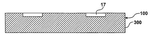
이제 도 5a~5d를 참조하면, 본 발명은 슬라이딩 베어링(8)의 제작 방법(100)을 포함하고 있다. 일 실시예에서, 방법(100)은 베어링 면(12)을 가지는 제1 재료의 베어링 부재(8)를 제조하는 단계(200); 베어링 면(12)의 일부분이 공동(17)에 상응하도록 베어링 면에 다수의 공동(17)을 형성하는 단계(300); 유체 폴리머 층이 다수의 공동(17)에 상응하는 베어링 면(12)의 부분을 제외하고 실질적으로 베어링 면(12)의 전체를 덮도록 유체 폴리머(54) 층을 베어링 면에 퇴적시키는 단계(400); 및 공동(17) 내에 다수의 일치하는 베어링 면 형상부(14)를 형성하기 위해 제2 재료를 공동(17) 내에 퇴적시키는 단계(500)를 포함하고 있다. Referring now to FIGS. 5A-5D, the present invention includes a
도 5a를 참조하면, 베어링 면(12)을 가지는 제1 재료의 베어링 부재(8)를 제조하는 단계(200)가 예시되어있다. 여기에서 설명된 바와 같이, 베어링 부재(8)는 스러스트 와셔(10)(도 1~4 참조), 피스톤 또는 실린더(29)(도 8, 10 및 11 참조) 및 슬리브 베어링(28)(도 9 참조)과 같은, 다수의 주지의 슬라이딩 베어링 부재(8) 를 포함할 수 있다. 제1 재료는 여기에 설명된 임의의 적절한 베어링 재료로 구성될 수 있다. 베어링 부재(8)를 제조하는 단계(200)는 베어링(8)에 선택된 제1 재료에 좌우하여, 여기에서 설명된 다수의 주지의 제조 방법을 채용하여 실행될 수 있다. 제조 방법의 예는 주조 단조, 소결, 사출 성형 등과 같은 성형을 포함하고 있다. 베어링 부재(8)를 제조하는 단계(200)는 또한 보조의 마무리 작업, 상세하게는 기계가공, 연삭, 연마 등 다른 주지의 마무리 작업과 같이 베어링이 복합적인 베어링 면을 가질 수 있는 경우(예를 들면 여기에 설명된 바와 같은 피스톤의 경우)에 베어링 면(12), 즉 면을 마련하는 마무리 작업을 포함할 수 있다. Referring to FIG. 5A, a
도 5는 적은 비용으로 가공된 표면을 얻을 수 있는 한 공정을 도시하고 있다. 제1 단계는 표면의 그루브(grooving)에 마이크로 전해가공(ECM)을 가하는 것이다. 캐소드는 자기장을 제어하도록 패턴을 형성할 것이다. 제2 단계는 그루브 또는 공동 내를 제외하고 상면에 얇은 겔 층을 도포하는 것이다. 이는 도금 또는 압연에 의해 행해질 수 있다. 겔이 공동 내에 들어가지 않도록 폴리머의 표면 장력이 제어된다. 제3 단계는 세라믹, 크롬 또는 PTFE등과 같은 패드 재료로 표면을 전기 코팅하는 것이다. 이 목적에 맞게 여러 개의 코팅법이 사용될 수 있다. 코팅법은 정전 코팅, 전착 도장(electrophoretic doposition), 전기 도금, 및 전기-플라즈마 도금을 포함하고 있다. 주어진 패드 재료를 위한 가장 적절한 코팅법이 선택될 것이다. 이러한 모든 전기 코팅법은 전도성 있는 면 위에만 코팅 재료를 퇴적시킬 수 있으므로, 패드 재료는 공동만을 채워 기초부상에서 쌓아 올려질 것이다. 퇴적 후, 경질이지않은 세라믹 재료를 위한 소결이 실행된다. PTFE를 위한 부가의 가열 단계가 요구된다. 표면상에 있는 겔 또는 다른 희생층을 가열 또는 용해로 제거할 수 있다. Figure 5 illustrates one process by which a machined surface can be obtained at low cost. The first step is to apply micro electrolytic machining (ECM) to the grooves of the surface. The cathode will form a pattern to control the magnetic field. The second step is to apply a thin layer of gel to the top surface except in the groove or cavity. This can be done by plating or rolling. The surface tension of the polymer is controlled so that the gel does not enter the cavity. The third step is to electrically coat the surface with a pad material such as ceramic, chromium or PTFE. Several coating methods can be used for this purpose. Coating methods include electrostatic coating, electrophoretic doposition, electroplating, and electro-plasma plating. The most appropriate coating method will be chosen for a given pad material. All of these electrocoating methods can deposit the coating material only on the conductive side, so that the pad material will only build up on the foundation by filling the cavity. After deposition, sintering is performed for the non-hard ceramic material. An additional heating step for PTFE is required. Gels or other sacrificial layers on the surface may be removed by heating or dissolution.
도 6은 더 높은 형상부를 형성하기 위한 또 다른 공정을 도시하고 있다. 제1 단계는 포토레지스트의 이미지를 부품의 표면상에 도포하는 것이다. 이 리소그래피 공법은 포토레지스트 도포, UV 노출, 및 레지스트 현상을 포함하고 있다. 제2 단계는 포토레지스트 마스크를 통하여 ECM에 의해 공동을 형성하는 것이다. 제3 단계는 이 공동 내부에 패드 재료를 전기적으로 퇴적시켜 패드를 쌓아올리는 단계이다. 제4 단계는 표면으로부터 포토레지스트를 제거하는 것이다. 마지막 단계는 만일 퇴적된 재료가 금속이 아니라면 세라믹을 소결하거나 PTFE를 경화시키는 것이다. 6 illustrates another process for forming higher features. The first step is to apply an image of the photoresist onto the surface of the part. This lithography process involves photoresist application, UV exposure, and resist development. The second step is to form a cavity by the ECM through the photoresist mask. The third step is to stack pad material by electrically depositing pad material inside the cavity. The fourth step is to remove the photoresist from the surface. The final step is to sinter the ceramic or cure the PTFE if the deposited material is not metal.
이러한 방법, 특히 ECM은 높은 생산력을 가지고 있고 비용 효율적이다. ECM은 불과 몇 초 만에 부품의 면에 모든 공동을 형성할 수 있다. 코팅법의 몇몇, 예를 들면 전착 도장이 또한 단시간에 공동을 형성한다. ECM이 기본적인 방법이다. This method, in particular ECM, has high productivity and is cost effective. The ECM can form all the cavities in the face of the component in just a few seconds. Some of the coating methods, for example electrodeposition paint, also form cavities in a short time. ECM is the basic method.
도 12는 본 발명의 또 다른 실시예를 도시하고 있다. 도 12에서, 베어링 면(12)을 가지는 피스톤 링(60)의 형태인 슬라이딩 베어링(8)의 베어링 요소(6)는 원통형 패드(16) 형태인 다수의 베어링 면 형상부(14)를 포함하고 있다. 이러한 베어링 면 형상부(14)는 베어링 면(12) 상에 위치된 다수의 일치하는 형태의 (도 5에 잘 도시된)공동(17) 즉 리세스의 내부에 위치되어있고, 형상부 전부는 베어링 면(12)의 일부를 포함하고 있다. 베어링 면 형상부(14)는 외경 면 또는 내경 면 또는 둘 다에 형성될 수 있다. Figure 12 shows another embodiment of the present invention. In FIG. 12, the
본 발명의 여러 변경과 변화가 본 기술의 견지에서 가능함은 자명하다. 그러므로, 본 발명은 첨부된 청구범위의 범위 내에서, 상세하게 설명된 바와 다르게 실시될 수 있음을 이해할 수 있다. It is apparent that various modifications and variations of the present invention are possible in light of the present technology. Therefore, it is to be understood that the invention may be practiced otherwise than as specifically described within the scope of the appended claims.
Claims (26)
Applications Claiming Priority (2)
| Application Number | Priority Date | Filing Date | Title |
|---|---|---|---|
| US11/169,032 | 2005-06-28 | ||
| US11/169,032 US7458158B2 (en) | 2005-06-28 | 2005-06-28 | Method of making a sliding bearing |
Publications (1)
| Publication Number | Publication Date |
|---|---|
| KR20080022175A true KR20080022175A (en) | 2008-03-10 |
Family
ID=37565587
Family Applications (1)
| Application Number | Title | Priority Date | Filing Date |
|---|---|---|---|
| KR1020087000139A KR20080022175A (en) | 2005-06-28 | 2006-06-07 | Method of making a sliding bearing |
Country Status (6)
| Country | Link |
|---|---|
| US (1) | US7458158B2 (en) |
| EP (1) | EP1907142A2 (en) |
| JP (1) | JP2008544196A (en) |
| KR (1) | KR20080022175A (en) |
| CN (1) | CN101583442A (en) |
| WO (1) | WO2007001779A2 (en) |
Families Citing this family (48)
| Publication number | Priority date | Publication date | Assignee | Title |
|---|---|---|---|---|
| US7878777B2 (en) * | 2006-08-25 | 2011-02-01 | Denso Corporation | Scroll compressor having grooved thrust bearing |
| US9938865B2 (en) | 2008-07-22 | 2018-04-10 | Eaton Corporation | Development of a switching roller finger follower for cylinder deactivation in internal combustion engines |
| US9267396B2 (en) | 2010-03-19 | 2016-02-23 | Eaton Corporation | Rocker arm assembly and components therefor |
| US10415439B2 (en) | 2008-07-22 | 2019-09-17 | Eaton Intelligent Power Limited | Development of a switching roller finger follower for cylinder deactivation in internal combustion engines |
| US20190309663A9 (en) | 2008-07-22 | 2019-10-10 | Eaton Corporation | Development of a switching roller finger follower for cylinder deactivation in internal combustion engines |
| US9228454B2 (en) | 2010-03-19 | 2016-01-05 | Eaton Coporation | Systems, methods and devices for rocker arm position sensing |
| DE102008035698A1 (en) * | 2008-07-30 | 2010-02-04 | Mahle International Gmbh | Piston or piston part manufacturing method for internal combustion engine, involves forming passage opening of circular or oval shape in piston or piston part by electro-shaping using electrode with flat or conical end |
| US20110011200A1 (en) * | 2009-07-16 | 2011-01-20 | Koyo Bearings Usa Llc | Bearing for a Connecting Rod |
| US9194261B2 (en) | 2011-03-18 | 2015-11-24 | Eaton Corporation | Custom VVA rocker arms for left hand and right hand orientations |
| US10087790B2 (en) | 2009-07-22 | 2018-10-02 | Eaton Corporation | Cylinder head arrangement for variable valve actuation rocker arm assemblies |
| US11181013B2 (en) | 2009-07-22 | 2021-11-23 | Eaton Intelligent Power Limited | Cylinder head arrangement for variable valve actuation rocker arm assemblies |
| US9885258B2 (en) | 2010-03-19 | 2018-02-06 | Eaton Corporation | Latch interface for a valve actuating device |
| US9874122B2 (en) * | 2010-03-19 | 2018-01-23 | Eaton Corporation | Rocker assembly having improved durability |
| CN102223005A (en) * | 2010-04-13 | 2011-10-19 | 德昌电机(深圳)有限公司 | Rotor bearing arrangement |
| US20120227718A1 (en) * | 2011-03-11 | 2012-09-13 | Gyula Kis-Benedek | Flexible anti-crack slip-surface ceramic engine cylinder sleeve |
| DE102011102205A1 (en) | 2011-05-21 | 2012-11-22 | Mahle International Gmbh | Processing a sliding surface of component e.g. oil scraper ring that is useful for piston of internal combustion engine, comprises introducing micro recesses into surface by laser machining, and filling recesses with solid material |
| US9297411B2 (en) * | 2011-05-26 | 2016-03-29 | Us Synthetic Corporation | Bearing assemblies, apparatuses, and motor assemblies using the same |
| WO2012166890A1 (en) * | 2011-06-01 | 2012-12-06 | Thomson Industries, Inc. | Hybrid clam-shell linear bearing |
| CN102261374B (en) * | 2011-06-15 | 2014-04-09 | 罗立峰 | Dynamic pressure gas thrust ceramic bearing |
| DE102011114413A1 (en) * | 2011-09-26 | 2013-03-28 | Esk Ceramics Gmbh & Co. Kg | Hydrodynamic thrust bearing |
| US8668388B1 (en) | 2011-11-29 | 2014-03-11 | Us Synthetic Corporation | Bearing assemblies, apparatuses, and motor assemblies using the same |
| CN104246192B (en) | 2012-03-12 | 2017-02-15 | 费德罗-莫格尔公司 | Engine piston |
| US20130287326A1 (en) * | 2012-04-27 | 2013-10-31 | Roller Bearing Company Of America, Inc. | Spherical plain bearing with solid graphite lubricating plugs |
| EP2674645A1 (en) * | 2012-06-15 | 2013-12-18 | Siemens Aktiengesellschaft | Oil blockage ring |
| US9284980B1 (en) * | 2012-11-06 | 2016-03-15 | Us Synthetic Corporation | Heavy load bearings and related methods |
| GB2508915A (en) * | 2012-12-14 | 2014-06-18 | Mahle Int Gmbh | A thrust washer for a sliding bearing |
| GB2508914A (en) | 2012-12-14 | 2014-06-18 | Mahle Int Gmbh | A thrust washer for a sliding bearing |
| CN104903606B (en) * | 2012-12-31 | 2018-01-23 | 美国圣戈班性能塑料公司 | Torque limit component |
| DE102013204577A1 (en) * | 2013-03-15 | 2014-10-02 | Federal-Mogul Nürnberg GmbH | Coated pistons and process for their preparation |
| JP6526675B2 (en) * | 2013-12-13 | 2019-06-05 | シェフラー テクノロジーズ アー・ゲー ウント コー. カー・ゲーSchaeffler Technologies AG & Co. KG | Torque converter including status last bearing |
| GB2521389A (en) * | 2013-12-18 | 2015-06-24 | Skf Ab | Method of producing a raceway ring, inner ring or outer ring,and raceway ring |
| GB2521392A (en) * | 2013-12-18 | 2015-06-24 | Skf Ab | Method of producing a raceway ring, inner ring or outer ring, and raceway ring |
| DE102014000223A1 (en) * | 2014-01-09 | 2015-07-09 | Björn Schröder | Sliding body for a plastic molding machine |
| DE102014201563A1 (en) * | 2014-01-29 | 2015-07-30 | Schaeffler Technologies AG & Co. KG | Aerodynamic air bearing and method for its manufacture |
| CN105121090A (en) | 2014-03-03 | 2015-12-02 | 伊顿公司 | Valve actuating device and method of making same |
| EP3152449B1 (en) * | 2014-06-04 | 2018-07-11 | Koninklijke Philips N.V. | Hydrodynamic bearings |
| US9309923B1 (en) | 2014-12-05 | 2016-04-12 | Us Synthetic Corporation | Bearing assemblies including integrated lubrication, bearing apparatuses, and methods of use |
| US9523386B1 (en) | 2014-12-05 | 2016-12-20 | Us Synthetic Corporation | Bearing assemblies including integrated lubrication, bearing apparatuses, and methods of use |
| US20150129265A1 (en) * | 2015-01-14 | 2015-05-14 | Caterpillar Inc. | Wear assembly |
| JP6095134B2 (en) * | 2015-03-02 | 2017-03-15 | 大同メタル工業株式会社 | Underwater sliding member |
| GB2537857B (en) * | 2015-04-28 | 2020-12-16 | Mahle Int Gmbh | Thrust washer comprising a polymer running layer having a textured surface |
| EP3302178B1 (en) * | 2015-05-27 | 2020-03-25 | Steelcase Inc. | Telescopic column having sliding elements |
| US9954349B2 (en) | 2015-09-25 | 2018-04-24 | The Boeing Company | Two-part snap-together feedthroughs |
| CN106224370A (en) * | 2016-08-31 | 2016-12-14 | 诸暨市三传动科技有限公司 | A kind of steel coppering bimetallic necklace bearing |
| TWI674718B (en) * | 2017-08-21 | 2019-10-11 | 美商波音公司 | Two-part snap-together feedthroughs |
| EP3906367B1 (en) * | 2018-12-31 | 2024-04-10 | Saint-Gobain Performance Plastics Pampus GmbH | Strut bearing, assembly, and method of making and using the same |
| US11905584B2 (en) * | 2020-01-08 | 2024-02-20 | GM Global Technology Operations LLC | Apparatus and process for localized patterned surface hardening for light-weight alloys to increase wear resistance under lubricated contact |
| CN113510891B (en) * | 2021-04-23 | 2022-09-27 | 中国科学院兰州化学物理研究所 | Two-stage hole polyimide material, preparation method thereof, two-stage hole polyimide retainer and application thereof |
Family Cites Families (14)
| Publication number | Priority date | Publication date | Assignee | Title |
|---|---|---|---|---|
| US1194463A (en) | 1916-08-15 | bache | ||
| US259255A (en) | 1882-06-06 | Poiteth to william e | ||
| US174331A (en) | 1876-02-29 | Improvement in anti-friction bearings | ||
| US1581394A (en) | 1918-01-11 | 1926-04-20 | Dann Products Company | Composite element and method of making the same |
| US2431430A (en) * | 1938-12-13 | 1947-11-25 | Shaw Harry | Bearing and bearing surface |
| US3436129A (en) | 1967-01-09 | 1969-04-01 | Robert A James | Bearing |
| US3785711A (en) | 1972-05-12 | 1974-01-15 | Allis Chalmers | Support bearing and assembly for rotary kilns |
| JPH05126138A (en) | 1991-11-01 | 1993-05-21 | Hitachi Ltd | Sliding bearing and manufacturing thereof |
| US5462362A (en) | 1993-04-30 | 1995-10-31 | Nsk Ltd. | Wear resisting slide member |
| US5549394A (en) | 1994-11-10 | 1996-08-27 | Hycomp, Inc. | Bearing arrangement having a polyimide graphite-fiber reinforced composite embedded therein |
| JP3795146B2 (en) * | 1995-09-11 | 2006-07-12 | 株式会社ジェイテクト | Linear motion bearing and method for forming lubricating film on linear motion bearing |
| JP2004019758A (en) * | 2002-06-14 | 2004-01-22 | Daido Metal Co Ltd | Slide bearing |
| US7255933B2 (en) * | 2002-08-23 | 2007-08-14 | Senju Metal Industry Co., Ltd. | Multi-layer sliding part and a method for its manufacture |
| JP2004176757A (en) * | 2002-11-25 | 2004-06-24 | Aisin Seiki Co Ltd | Metal bearing and manufacturing method for metal bearing |
-
2005
- 2005-06-28 US US11/169,032 patent/US7458158B2/en not_active Expired - Fee Related
-
2006
- 2006-06-07 CN CNA200680022178XA patent/CN101583442A/en active Pending
- 2006-06-07 JP JP2008519327A patent/JP2008544196A/en active Pending
- 2006-06-07 EP EP06772501A patent/EP1907142A2/en not_active Withdrawn
- 2006-06-07 KR KR1020087000139A patent/KR20080022175A/en not_active Application Discontinuation
- 2006-06-07 WO PCT/US2006/022224 patent/WO2007001779A2/en active Application Filing
Also Published As
| Publication number | Publication date |
|---|---|
| US20060288579A1 (en) | 2006-12-28 |
| EP1907142A2 (en) | 2008-04-09 |
| WO2007001779A2 (en) | 2007-01-04 |
| WO2007001779A3 (en) | 2009-04-16 |
| JP2008544196A (en) | 2008-12-04 |
| US7458158B2 (en) | 2008-12-02 |
| CN101583442A (en) | 2009-11-18 |
Similar Documents
| Publication | Publication Date | Title |
|---|---|---|
| KR20080022175A (en) | Method of making a sliding bearing | |
| JP6417400B2 (en) | Sliding engine parts | |
| US5313919A (en) | Low friction reciprocating piston assembly | |
| CN1105834C (en) | Self-lubricated bearing | |
| Ahmed et al. | An overview of geometrical parameters of surface texturing for piston/cylinder assembly and mechanical seals | |
| KR100785504B1 (en) | Bearing element | |
| EP1762721A2 (en) | Internal combustion engine | |
| JP2006161563A (en) | Piston for internal combustion engine | |
| CN104395626B (en) | Split bearing | |
| US20080163751A1 (en) | Coated piston and coating method | |
| KR20080032034A (en) | Coated power cylinder components for diesel engines | |
| KR20100097036A (en) | Sliding member | |
| EP2643604B1 (en) | Bearing with integrated seals | |
| JP6263545B2 (en) | Sliding bearing provided with bearing substrate and polymer embedded body, and engine provided with the same | |
| US20080112659A1 (en) | Bearing Device | |
| CN101713298B (en) | Hydraulic motor provided with friction pair with nanometer graphite layer and method for processing nanometer graphite layer | |
| CN105518320A (en) | Bearing shell | |
| CN104696510A (en) | Anti-wear and anti-scuffing piston pin as well as manufacturing method thereof | |
| Dean et al. | Plain bearing materials: the role of tin | |
| GB2537857A (en) | Thrust washer comprising a polymer running layer having a textured surface | |
| CN102537064A (en) | Improved special bearing bush for racing car engine | |
| Ludema | Failures of sliding bearings | |
| SHARMA | PERFORMANCE STUDIES OF TEXTURED JOURNAL BEARING | |
| JPS624924A (en) | Abrasion resistant sliding member | |
| Holland et al. | Cylindrical magnetron sputtering for the production of wear-resistant and durable overlays of uniform thickness for journal bearings for application in high performance combustion engines |
Legal Events
| Date | Code | Title | Description |
|---|---|---|---|
| WITN | Application deemed withdrawn, e.g. because no request for examination was filed or no examination fee was paid |