KR20080011139A - Light-redirecting film containing optical modification layer - Google Patents
Light-redirecting film containing optical modification layer Download PDFInfo
- Publication number
- KR20080011139A KR20080011139A KR1020070076068A KR20070076068A KR20080011139A KR 20080011139 A KR20080011139 A KR 20080011139A KR 1020070076068 A KR1020070076068 A KR 1020070076068A KR 20070076068 A KR20070076068 A KR 20070076068A KR 20080011139 A KR20080011139 A KR 20080011139A
- Authority
- KR
- South Korea
- Prior art keywords
- optical
- film
- light
- redirecting film
- light redirecting
- Prior art date
Links
Images


Classifications
-
- G—PHYSICS
- G02—OPTICS
- G02B—OPTICAL ELEMENTS, SYSTEMS OR APPARATUS
- G02B5/00—Optical elements other than lenses
- G02B5/02—Diffusing elements; Afocal elements
- G02B5/0268—Diffusing elements; Afocal elements characterized by the fabrication or manufacturing method
-
- G—PHYSICS
- G02—OPTICS
- G02B—OPTICAL ELEMENTS, SYSTEMS OR APPARATUS
- G02B5/00—Optical elements other than lenses
- G02B5/02—Diffusing elements; Afocal elements
- G02B5/0205—Diffusing elements; Afocal elements characterised by the diffusing properties
- G02B5/021—Diffusing elements; Afocal elements characterised by the diffusing properties the diffusion taking place at the element's surface, e.g. by means of surface roughening or microprismatic structures
- G02B5/0221—Diffusing elements; Afocal elements characterised by the diffusing properties the diffusion taking place at the element's surface, e.g. by means of surface roughening or microprismatic structures the surface having an irregular structure
-
- G—PHYSICS
- G02—OPTICS
- G02B—OPTICAL ELEMENTS, SYSTEMS OR APPARATUS
- G02B6/00—Light guides; Structural details of arrangements comprising light guides and other optical elements, e.g. couplings
- G02B6/0001—Light guides; Structural details of arrangements comprising light guides and other optical elements, e.g. couplings specially adapted for lighting devices or systems
- G02B6/0011—Light guides; Structural details of arrangements comprising light guides and other optical elements, e.g. couplings specially adapted for lighting devices or systems the light guides being planar or of plate-like form
- G02B6/0033—Means for improving the coupling-out of light from the light guide
- G02B6/005—Means for improving the coupling-out of light from the light guide provided by one optical element, or plurality thereof, placed on the light output side of the light guide
- G02B6/0051—Diffusing sheet or layer
-
- G—PHYSICS
- G02—OPTICS
- G02B—OPTICAL ELEMENTS, SYSTEMS OR APPARATUS
- G02B6/00—Light guides; Structural details of arrangements comprising light guides and other optical elements, e.g. couplings
- G02B6/0001—Light guides; Structural details of arrangements comprising light guides and other optical elements, e.g. couplings specially adapted for lighting devices or systems
- G02B6/0011—Light guides; Structural details of arrangements comprising light guides and other optical elements, e.g. couplings specially adapted for lighting devices or systems the light guides being planar or of plate-like form
- G02B6/0033—Means for improving the coupling-out of light from the light guide
- G02B6/005—Means for improving the coupling-out of light from the light guide provided by one optical element, or plurality thereof, placed on the light output side of the light guide
- G02B6/0053—Prismatic sheet or layer; Brightness enhancement element, sheet or layer
-
- G—PHYSICS
- G02—OPTICS
- G02F—OPTICAL DEVICES OR ARRANGEMENTS FOR THE CONTROL OF LIGHT BY MODIFICATION OF THE OPTICAL PROPERTIES OF THE MEDIA OF THE ELEMENTS INVOLVED THEREIN; NON-LINEAR OPTICS; FREQUENCY-CHANGING OF LIGHT; OPTICAL LOGIC ELEMENTS; OPTICAL ANALOGUE/DIGITAL CONVERTERS
- G02F1/00—Devices or arrangements for the control of the intensity, colour, phase, polarisation or direction of light arriving from an independent light source, e.g. switching, gating or modulating; Non-linear optics
- G02F1/01—Devices or arrangements for the control of the intensity, colour, phase, polarisation or direction of light arriving from an independent light source, e.g. switching, gating or modulating; Non-linear optics for the control of the intensity, phase, polarisation or colour
- G02F1/13—Devices or arrangements for the control of the intensity, colour, phase, polarisation or direction of light arriving from an independent light source, e.g. switching, gating or modulating; Non-linear optics for the control of the intensity, phase, polarisation or colour based on liquid crystals, e.g. single liquid crystal display cells
- G02F1/133—Constructional arrangements; Operation of liquid crystal cells; Circuit arrangements
- G02F1/1333—Constructional arrangements; Manufacturing methods
- G02F1/1335—Structural association of cells with optical devices, e.g. polarisers or reflectors
- G02F1/1336—Illuminating devices
- G02F1/133602—Direct backlight
- G02F1/133606—Direct backlight including a specially adapted diffusing, scattering or light controlling members
- G02F1/133607—Direct backlight including a specially adapted diffusing, scattering or light controlling members the light controlling member including light directing or refracting elements, e.g. prisms or lenses
-
- G—PHYSICS
- G02—OPTICS
- G02F—OPTICAL DEVICES OR ARRANGEMENTS FOR THE CONTROL OF LIGHT BY MODIFICATION OF THE OPTICAL PROPERTIES OF THE MEDIA OF THE ELEMENTS INVOLVED THEREIN; NON-LINEAR OPTICS; FREQUENCY-CHANGING OF LIGHT; OPTICAL LOGIC ELEMENTS; OPTICAL ANALOGUE/DIGITAL CONVERTERS
- G02F2202/00—Materials and properties
- G02F2202/02—Materials and properties organic material
- G02F2202/022—Materials and properties organic material polymeric
Abstract
Description
본 발명은 광학적 변형층을 포함하는 복수의 광학 요소를 포함하는 광 변향 폴리머 필름의 구조에 관한 것이다. 특히, LCD 디스플레이 소자에 빛 에너지를 유도하기에 적합한 넓고 일정한 빛의 출력을 갖는 광 변향 필름에 관한 것이다.The present invention relates to the structure of a light redirecting polymer film comprising a plurality of optical elements comprising an optically deforming layer. In particular, it relates to a light redirecting film having a wide and constant light output suitable for inducing light energy into an LCD display element.
일반적으로, 광 변향 필름(Light Redirecting Films)은 얇고 투명한 광학 필름 또는 기판으로, 상기 필름을 통과한 빛을 재분배하여 상기 필름에서 출사하는 빛의 분배가 상기 필름의 표면에 더욱 수직으로 유도된다. 일반적으로, 광 변향 필름은 필름의 광 출사 표면에 정렬된 프리즘 형상의 그루브(grooves), 렌즈 형상의 홈 또는 피라미드가 제공되어 필름에서 출사광 광선을 위해 필름의 각도/공기 경계면이 변하고, 필름의 표면에 더 수직한 방향으로 재분배되도록 그루브의 굴절 표면에 수직한 평면에서 이동하는 입사광 요소의 분포를 유도한다. 이러한 광 변향 필름은, 예를 들어, 액정 디스플레이(LCD), 랩탑 컴퓨터, 워드 프로세서, 비행기 디스플레이, 휴대폰, PDA 등에서 휘도를 향상시키고 디스플레이를 더 밝게 하기 위해 사용된다. 종래의 광 변향 필름은 광 변향 필름이 액정이나 다른 디스플레이에 사 용될 때 가시적인 무아레(Moire) 패턴 때문에 문제가 있었다. 광 변향 필름의 표면 요소는 백라이트 어셈블리에서 이용되는 다른 광학 필름들, 바람직하지 않은 효과인 무아레 현상을 발생시키는 도광판의 후면에 인쇄된 도트 패턴이나 3차원 소자들, 디스플레이의 액정 부분 내의 픽셀 패턴과 상호 작용한다. 무아레 현상을 감소시키기 위해 종래에 알려진 방법은 광 변향 필름을 제거하여 렌즈 형상 배열이 시트의 어느 측면에서도 수직하지 않게 하는 것이다. 이것은 렌즈 형상 배열을 다른 광 변향 필름 또는 디스플레이 전자제품에 상대적인 각도를 갖도록 만든다. 또한, 사용되는 방법에는 주기적으로 선형 배열을 따라 높이를 변화시키기 위해, 필름의 선형 배열의 반대 측에 확산층을 추가하기 위해, 또는 선형 배열의 능선(ridges)을 둥글게 하기 위해, 선형 배열 소자의 폭에 의해 선형 배열을 랜덤화(randomizing) 하는 것을 포함한다. 또한, 상술한 무아레 현상을 감소시키기 위한 기술은 축상 휘도(on-axis brightness)의 감소를 야기하거나 무아레 문제를 적절히 해결하도록 작용하지 않는다. 무아레 및 축상 휘도는 연관된 경향이 있으며, 높은 축상 게인을 갖는 필름은 시스템에서 높은 무아레를 갖는 것을 의미한다. 적절한 축상 게인을 유지하는 한편 무아레를 감소시킬 수 있는 것이 유리할 것이다.In general, Light Redirecting Films are thin transparent optical films or substrates that redistribute the light passing through the film so that the distribution of light exiting the film is directed more perpendicular to the surface of the film. Generally, the light redirecting film is provided with prismatic grooves, lenticular grooves or pyramids aligned with the light exit surface of the film such that the angle / air interface of the film changes for the outgoing light rays from the film, The distribution of incident light elements moving in a plane perpendicular to the refractive surface of the groove is redistributed in a direction more perpendicular to the surface. Such light redirecting films are used, for example, in liquid crystal displays (LCDs), laptop computers, word processors, airplane displays, mobile phones, PDAs, and the like to improve brightness and make the display brighter. Conventional light redirecting films have suffered from moire patterns that are visible when the light redirecting films are used in liquid crystals or other displays. The surface elements of the light redirecting film interact with other optical films used in the backlight assembly, dot patterns or three-dimensional elements printed on the backside of the light guide plate, which cause an undesirable moire phenomenon, and pixel patterns within the liquid crystal portion of the display. Works. A method known in the art to reduce the moire phenomenon is to remove the light redirecting film so that the lens-like arrangement is not perpendicular to either side of the sheet. This makes the lens-like arrangement at an angle relative to other light redirecting films or display electronics. The method used also includes the width of the linear array element to periodically vary the height along the linear array, to add a diffusion layer on the opposite side of the linear array of films, or to round the ridges of the linear array. Randomizing a linear array. In addition, the technique for reducing the above moire phenomenon does not work to cause a reduction in on-axis brightness or to properly solve the moire problem. Moire and on-axis brightness tend to be associated, meaning films with high on-axis gain have high moire in the system. It would be advantageous to be able to reduce moire while maintaining adequate on-axis gain.
추가적으로, 상대적으로 액정 디스플레이 구성의 수와 비교되는 광 변향 필름의 수가 거의 없다. 각 디스플레이 구성은 바람직한 결과를 얻기 위해 선택된다. 축상 게인, 시야각, 무아레 감소 및 전체 광 출력은 모두 다른 필름을 다른 구성에 결합하여 맞추어진다. 시스템에 사용되는 광 변향 필름은 오직 소수의 다른 광 변향 표면 조직만 가능하기 때문에 제한된다. 디스플레이 소자의 바람직한 결과를 사 용자가 바꿀 수 있는 광 변향 필름을 갖는 것이 바람직할 것이다. In addition, there are relatively few numbers of light redirecting films compared to the number of liquid crystal display configurations. Each display configuration is selected to achieve the desired result. Axial gain, viewing angle, moire reduction, and overall light output are all tailored by combining different films into different configurations. Light redirecting films used in the system are limited because only a few different light redirecting surface textures are possible. It would be desirable to have a light redirecting film that allows the user to change the desired results of the display device.
일반적으로, 광 유도 필름(light directing films)은 수직으로부터 40도 내지 90도 사이의 각도의 조도 소비에서 높은 축상 조도를 제공한다. 이 높은 축상 광 유도 필름은 배터리를 위해 전력 소비를 감소시키는 높은 축상 휘도를 갖고 적정 수준의 시야 프라이버시를 제공하는 랩탑 컴퓨터 및 게임기와 같은 휴대용 디스플레이 소자에서 유용하다. 대중적 감상을 의도하는 TV 및 모니터를 위해, 넓은 범위의 시야각에 걸쳐 높은 휘도가 지속적인 영상 및 비디오의 감상을 위해 고려된다. 넓은 범위의 시야각에 걸쳐 높은 휘도를 제공할 수 있는 광 유도 필름을 갖는 것이 바람직할 것이다.In general, light directing films provide high on-axis roughness at roughness consumption at angles between 40 degrees and 90 degrees from vertical. This high on-axis light guiding film is useful in portable display devices such as laptop computers and game machines, which have high on-axis brightness that reduces power consumption for batteries and provide adequate levels of viewing privacy. For TVs and monitors intended for public viewing, high luminance over a wide range of viewing angles is considered for the viewing of continuous images and video. It would be desirable to have a light guide film that can provide high brightness over a wide range of viewing angles.
미국 특허 제5,919,551호(Cobb, Jr. 등)는 무아레 간섭 패턴의 가시성을 줄이기 위해 다양한 피치(pitch) 피크(peak) 및/또는 그루브(groove)를 갖는 선형 배열 필름을 청구한다. 피치 변화는 인접한 피크 및/또는 골(valley) 또는 인접한 피크 및/또는 골의 쌍의 그룹에 걸칠 수 있다. 선형 배열 소자의 피치 변화가 무아레를 감소시킬 수 있는 반면, 필름의 선형 소자는 여전히 백라이트 도광판 및 디스플레이의 액정 섹션 내의 전자기기 상의 도트(dot) 패턴과 상호작용한다.US Pat. No. 5,919,551 to Cobb, Jr. et al. Claims a linear array film having various pitch peaks and / or grooves to reduce the visibility of moire interference patterns. Pitch changes can span groups of adjacent peaks and / or valleys or pairs of adjacent peaks and / or valleys. While the pitch change of the linear array element can reduce moire, the linear element of the film still interacts with the dot pattern on the electronics in the liquid crystal section of the backlight light guide plate and display.
미국 특허 제6,354,709호는 능선(ridgeline)을 따라 높이가 변하고 능선 또한 좌우로 움직이는 선형 배열을 갖는 필름을 개시한다. 상기 필름이 광을 변향하고(redirect) 능선을 따른 높이 변화가 무아레를 약간 감소시키는 반면, 시스템에 사용될 때 상대적으로 높은 축상 게인을 유지하는 동안 필름의 무아레를 감소시키는 중요한 필름을 갖는 것이 바람직하다. U. S. Patent No. 6,354, 709 discloses a film having a linear arrangement that varies in height along the ridgeline and the ridge also moves from side to side. While the film redirects light and changes in height along the ridges slightly reduce moire, it is desirable to have an important film that reduces the moire of the film while maintaining a relatively high on-axis gain when used in the system.
미국 특허출원 제2001/0053075호(Parker 등)는 LCD 소자에서 높은 축상 게인을 발생시키는 광 변향을 위한 각 광학 요소의 사용을 개시한다.US patent application 2001/0053075 (Parker et al.) Discloses the use of each optical element for light deflection that produces high on-axis gain in LCD devices.
미국 특허 제6,721,102호(Bourdelais 등)는 복합 폴리머 렌즈로 형성된 가시광 확산기(diffuser)를 개시한다. 미국 특허 제6,721,102호에 개시된 복합 렌즈는 낮은 종횡비(aspect ratio)의 폴리머 기반 렌즈의 표면 상에 마이크로미터 크기의 폴리머 렌즈를 추가하여 생성된다. 작은 렌즈에 대한 큰 렌즈의 비율은 2:1 내지 30:1 이다. 미국 특허 제6,721,102호에 개시된 확산기는 광원의 확산, 특히 LCD 백라이트 소스로 유용하다.U. S. Patent No. 6,721, 102 (Bourdelais et al.) Discloses a visible light diffuser formed of a composite polymer lens. The composite lens disclosed in US Pat. No. 6,721,102 is created by adding a micrometer sized polymer lens on the surface of a low aspect ratio polymer based lens. The ratio of large lenses to small lenses is 2: 1 to 30: 1. The diffuser disclosed in US Pat. No. 6,721,102 is useful as a diffuse light source, in particular as an LCD backlight source.
미국 특허 제6,583,936호(Kaminsky 등)는 광 폴리머 확산 렌즈의 미세한 복제를 위한 패터닝된 롤러를 개시한다. 패터닝된 롤러는 다양한 크기의 입자를 갖는 롤러로 제1비드를 블래스팅(blasting)하고, 이어서, 미세 노듈(micro-nodule)을 생성하는 크로밍(chroming) 공정에 의해 생성된다. 롤러의 제조 방법은 입사광 에너지를 확산시키기 위한 광 확산 렌즈에 적합하다.U. S. Patent No. 6,583, 936 (Kaminsky et al.) Discloses a patterned roller for fine replication of an optical polymer diffuser lens. The patterned roller is produced by a chroming process that blasts the first bead into rollers having particles of various sizes and then produces micro-nodule. The method for producing a roller is suitable for a light diffusing lens for diffusing incident light energy.
미국 특허출원 제2005/00247554호(Epstein 등)는 랜덤(random) 확산(scattering)을 생성하기 위해 바람직하게는 2 내지 5 마이크로미터의 직경을 갖는 폴리머 비드를 포함하는 매트릭스(matrix) 폴리머로 코팅된 표면구조를 개시한다.U.S.
미국 특허출원 제2005/0047112호(Chen 등)는 표면에 프리즘이 형성된 도광판을 개시한다. 프리즘의 표면은 전송된 광을 확산시키기 위해 이산화티탄(titanium dioxide), 산화실리콘(silicone dioxide) 또는 산화알루미늄(aluminum oxide)으로 이루어진 코팅된 무기물 나노-입자 층을 포함한다.US
미국 특허출원 제2005/0140860호(Olczak)는 제2표면 구조에 의해 기능이 조절되는 제1표면 구조가 정의된 광학 필름으로, 제1표면이 필름에 입사광을 확산시키는 역할을 수행하고 제2표면 역시 입사광을 확산시키는 기능을 수행하는 광학 필름을 개시한다.US Patent Application No. 2005/0140860 (Olczak) is an optical film in which a first surface structure whose function is controlled by a second surface structure is defined. The first surface serves to diffuse incident light on the film and the second surface. Also disclosed is an optical film that performs the function of diffusing incident light.
미국 특허출원 제2005/0174646호(Cowan 등)는 특정한 범위의 각도로 입사광을 전송하거나 반사시키는, 반사하는 확산부를 개시한다.US
넓은 시야각 범위에서 높은 휘도를 제공하는 광 변향 필름을 제공한다.Provided is a light redirecting film that provides high brightness over a wide viewing angle range.
본 발명은 (a) 광학 요소들 및 (b) 상기 광학 요소들 위에 위치하는 마이크로 비드와 바인더를 포함하는 광 변형 층을 포함하는 광 출사 표면을 포함하되, 적어도 1.20의 광학 게인을 갖는 광 변향 필름을 제공한다.The present invention provides a light redirecting film comprising (a) an optical exit surface comprising (a) a light modifying layer comprising a binder and a microbead and a microbead positioned over the optical elements, the optical redirecting film having an optical gain of at least 1.20. To provide.
본 발명은 시야각의 넓은 범위에서 높은 휘도를 갖는 광 변향 필름을 포함하는 광학 장치를 제공한다.The present invention provides an optical device comprising a light redirecting film having a high luminance over a wide range of viewing angles.
본 발명은 도면과 함께 읽을 때 이하의 상세한 설명으로부터 가장 잘 이해된다. 다양한 특성은 일정한 비율로 도시될 필요가 없음을 강조한다.The invention is best understood from the following detailed description when read in conjunction with the drawings. It is emphasized that the various features need not be drawn to scale.
본 발명은 종래의 광 변향 필름들과 비교하여 많은 이점을 가진다. 본 발명은 넓은 범위의 시야각들에 대하여 높은 레벨의 휘도(brightness)를 제공한다. 고휘도 및 넓은 시야각의 조합은 LCD TV 및 모니터 시장에 잘 맞는다. 고휘도는 LCD 백라이트 에너지의 효율적인 이용을 고려하고, 넓은 시야각은 모니터들과 TV 제품들에서 대표적인 넓은 범위의 시야각들에 대하여 LCD 이미지의 평평하고 균등한 휘도를 보장한다. 더 나아가, 필름은 종래의 광 변향 필름들과 비교하여 더 부드러운 앵귤러 컷오프(angular cut-off)를 제공한다. 종래의 광 변향 필름들은, 조도(illumination)이 몇몇 각도들에 대하여 현저하게 변하게 하는 엄격한(hard) 앵귤러 컷오프를 가진다. 이러한 엄격한 앵귤러 컷오프가 랩탑 컴퓨터와 같은 개인 시청 장치에 대하여 만족스럽고 선호되기 조차하는 반면에, 엄격한 앵귤러 컷오프는 TV 및 공중 시청 모니터들과 같이 더 큰 각도에 대하여 시청되는 LCD 장치에 대하여 이미지 품질의 감소를 유발시킬 수 있다. The present invention has many advantages over conventional light redirecting films. The present invention provides a high level of brightness over a wide range of viewing angles. The combination of high brightness and wide viewing angle is well suited for the LCD TV and monitor market. High brightness allows for efficient use of LCD backlight energy, and a wide viewing angle ensures flat and even brightness of the LCD image over a wide range of viewing angles typical of monitors and TV products. Furthermore, the film provides a smoother angular cut-off compared to conventional light redirecting films. Conventional light redirecting films have a hard angular cutoff that causes the illumination to vary significantly for some angles. While this strict angular cutoff is satisfactory and even preferred for personal viewing devices such as laptop computers, the strict angular cutoff reduces image quality for LCD devices viewed for larger angles, such as TVs and public viewing monitors. May cause.
광학 요소들의 표면에 적용되는 광학적 변형층(optical modification layer)은 종래 기술의 광 변향 필름에 비하여 더 많은 입사광이 광 변향 필름을 통과하도록 한다. 광학 요소들의 표면에 적용되는 광학적 변형층은 광 변향 필름 내에서 전체 내부 반사량을 "제거하거나(frustrate)" 감소시킨다는 것이 발견되었다. 광 변향 필름의 전체 내부 반사의 제거는 광학적 변형층이 없는 동일한 광 변향 필름에 비하여 5 내지 14% 더 높은 광 출력을 유발한다. An optical modification layer applied to the surface of the optical elements allows more incident light to pass through the light redirecting film as compared to prior art light redirecting films. It has been found that the optical strain layer applied to the surface of the optical elements "frustrates" or reduces the total internal reflection in the light redirecting film. Elimination of the total internal reflection of the light redirecting film results in a 5-14% higher light output compared to the same light redirecting film without the optical strain layer.
필름 개개의 광학 요소들의 필름상의 위치는 무아레 리덕션(Moire reduction)과 축상 게인(on-axis gain) 사이의 트레이드오프(tradeoff)의 균형을 맞추며, 무아레를 상당히 감소시키는 동안 상대적으로 높은 축상 게인을 생성한다. 라인들 또는 점들의 두 개 이상의 규칙적인 세트들(regular sets)이 오버랩될 때, 무아레 패턴들이 나타난다. 이것은 라인들 또는 형상들을 반복시키는 패턴을 유발시키며, 라인 크기 및 프리컨시(frequency)는 두 개의 패턴들의 상호 작용에 의존한다. LCD 장치와 같은 디스플레이 장치에서, LCD 장치의 시청자에 의해 관찰될 수 있는 무아레 패턴들은, 이들이 디스플레이되는 정보 또는 이미지의 품질을 방해하기 때문에 용납될 수 없다. 본 발명의 광 변향 필름은, 종래 기술의 광 변향 필름 들에 비하여 무아레를 감소시키는 동시에 축상 게인량을 유지시킨다. 개별 요소들 및 광학적 변형층의 크기 및 형상 분포들은 디스플레이 또는 시청 장치 각각에 대하여 맞춤 설계될 수 있다.The film's on-film position of the individual optical elements balances the tradeoff between moire reduction and on-axis gain, creating a relatively high on-axis gain while significantly reducing moiré. do. Moire patterns appear when two or more regular sets of lines or points overlap. This results in a pattern of repeating lines or shapes, the line size and frequency depending on the interaction of the two patterns. In a display device such as an LCD device, the moire patterns that can be observed by the viewer of the LCD device are unacceptable because they interfere with the quality of the information or image displayed. The light redirecting film of the present invention reduces moire and maintains on-axis gain amount as compared with light redirecting films of the prior art. The size and shape distributions of the individual elements and the optically deformable layer can be custom designed for each display or viewing device.
더 나아가, 본 발명의 광 변향 필름은, 더 효과적으로 광을 변향시키기 위하여 도광판(light guide plate)의 광 출력 및 광원(light source)에 대하여 맞춤 설계될 수 있다. 개별 광학 요소들은 설계 파라미터들 내에서 필름을 매우 플렉서블하게 만들며, 상이한 크기, 형상 또는 배향(orientation)의 상이한 개별 광학 요소들이 필름 표면 전체에 대하여 사용되어 필름에 입사되는 광을 가장 효과적으로 처리한다. 예를 들어, 각도 함수로서의 광 출력이 도광판 상의 모든 점들에 대하여 알려졌다면, 상이한 형상들, 크기들 또는 배향을 가지는 개별 광학 요소들을 사용하는 광 변향 필름은 도광판을 출사하는 광을 효과적으로 처리하도록 설계될 수 있었다. Furthermore, the light redirecting film of the present invention can be custom designed for the light output and light source of the light guide plate in order to redirect light more effectively. Individual optical elements make the film very flexible within the design parameters, and different individual optical elements of different sizes, shapes or orientations are used throughout the film surface to most effectively treat light incident on the film. For example, if the light output as an angle function is known for all points on the light guide plate, the light redirecting film using individual optical elements having different shapes, sizes or orientations may be designed to effectively process the light exiting the light guide plate. Could.
두 개의 반사 표면들(예를 들어 액정 디스플레이에서 광 변향 필름들 또는 다른 광학 필름들)이 상호 간에 충분히 근접하여 거리가 거의 광의 파장으로 시작될 때, 뉴턴 링(Newton ring)들이 발생된다. 광자(photon)들은 두 표면들을 통과할 뿐만 아니라 두 표면들 사이에서 반사되어 간섭 효과(interference effect)를 만들어 낸다. 뉴턴 링들은 액정 디스플레이에 대한 시청자에게 바람직하지 않다. 본 발명의 필름은 일정 비율의 개별 요소들이 광 변향 필름 상에서 다른 요소들 위로 연장되도록 함으로써, 뉴턴 링을 감소시킨다.Newton rings are generated when two reflective surfaces (eg, light redirecting films or other optical films in a liquid crystal display) are sufficiently close to each other and the distance begins at a wavelength of light almost. Photons not only pass through the two surfaces but also reflect between them, creating an interference effect. Newton rings are undesirable for viewers for liquid crystal displays. The film of the present invention reduces the Newton ring by allowing a proportion of individual elements to extend over other elements on the light redirecting film.
본 발명의 필름은, 단지 하나의 크기를 가지는 요소를 구비한 광 변향 필름 보다 다중 크기의 요소들을 구비한 더 큰 유효 피치(effective pitch)를 가진다. 더 큰 유효 피치를 가진다는 것은, 동일한 크기 랜드(land)를 가진 더 오버랩된 필름보다 더 큰 축상 게인을 가질 것, 또는 제조 허용 오차들(manufacturing tolerances)이 감소될 수 있어서 동일한 축상 게인을 가지기 위하여 랜드가 더 커질 수 있었다라는 것을 의미한다. 제조 허용 오차들을 감소시키는 것은 필름 제조의 생산성을 향상시킬 수 있다.Films of the invention have a larger effective pitch with elements of multiple sizes than light redirecting films with elements of only one size. To have a larger effective pitch means to have a larger on-axis gain than a more overlapped film with the same size land, or to have the same on-axis gain as manufacturing tolerances can be reduced It means that the land could get bigger. Reducing manufacturing tolerances can improve the productivity of film manufacturing.
본 발명은, 스크래칭 및 마모에 견디며, UV 경화된 폴리아크릴레이트(polyacrylate)로부터 만들어진 종래 기술의 다른 민감한 광 변향 필름들과 비교하여 기계적으로 더 강한 것을 보여온 베이스 시트 및 바인더에 대하여 폴리머들을 사용한다.The present invention uses polymers for base sheets and binders that resist scratching and abrasion and have been shown to be mechanically stronger compared to other sensitive light redirecting films of the prior art made from UV cured polyacrylates.
또한, 본 발명의 실시예들은 낮은 마찰 계수 표면, 감소된 유전율(dielectric constant), 내마모성, 증가된 단단함(stiffness), 더 낮은 스캐터링(scattering), 향상된 무아레, 더 높은 광 출력 및 향상된 착색(coloration)을 제공할 수 있다. 이들 및 다른 이점들이 아래의 상세한 설명으로부터 명백할 것이다. In addition, embodiments of the present invention provide low friction coefficient surfaces, reduced dielectric constant, wear resistance, increased stiffness, lower scattering, improved moire, higher light output, and improved coloration. ) Can be provided. These and other advantages will be apparent from the detailed description below.
여기서 사용된, "투명(tranparent)"은 상당한 편향(deviation) 또는 흡수(absorption)없이 방사(radiation)를 통과시킬 수 있는 능력을 의미한다. 본 발명에서 "투명" 물질은 90% 보다 큰 스펙트럼 전달(spectral transmission)을 가지는 물질로서 정의된다. 용어 "광(light)"은 가시 광선(visible light)을 의미한다. 용어 "폴리머 필름(polymeric film)"은 폴리머들을 포함하는 필름을 의미한다. 용어 "폴리머"는 호모 폴리머(homo-polymer), 블럭 코-폴리머(block co-polimer), 코-폴리머(co-polymer) 및 폴리머 블렌드(polymer blend)를 의미한다. 여기서 사용된 마이크로비드(microbead) 용어는, 0.1 내지 30 마이크로미터의 직경 또는 주축(major axis)을 가지는 단면상으로 원에서 타원까지인 비드를 의미한다.As used herein, "tranparent" refers to the ability to pass radiation without significant deviation or absorption. In the present invention, "transparent" material is defined as a material having spectral transmission greater than 90%. The term "light" means visible light. The term "polymeric film" means a film comprising polymers. The term "polymer" refers to homo-polymers, block co-polimers, co-polymers and polymer blends. As used herein, the term microbead refers to beads from circle to ellipse on a cross section having a diameter or major axis of 0.1 to 30 micrometers.
광학 필름과 관계되어, 개별 광학 요소들은, 광학 필름에서 돌출부(projection)들 또는 오목부들(depression)들이 될 수 있는 명확한 형상의 요소들을 의미한다. 개별 광학 요소들은 광학 필름의 길이 및 폭에 비하여 작다. 용어 "구부러진 표면(curved surface)"은 적어도 하나의 평면에서 구부러짐을 가지는 필름 상의 3차원 요소를 가리키기 위하여 사용된다. "웨지 형상의 요소(wedge shaped element)들은 하나 이상의 경사진 표면을 포함하는 요소를 가리키기 위하여 사용되고, 이 표면들은 평평한 표면과 구부러진 표면의 결합일 수 있다. 용어 "광학 필름"은 전달된 입사광의 특성을 변화시키는 얇은 폴리머 필름을 가리키기 위하여 사용된다. 예를 들어, 변향 광학 필름은 1.0 보다 큰 광학 게인(출력/입력)을 제공한다. 광 처리 물질(light management material)의 광학 게인(Optical Gain; OG)은 기준 입력 루미넌스에 의해 나눠지는 광 처리 물질의 루미넌스로서 정의된다. 만일 광 분포(light distribution)들이 거의 등방성이 아니라면, 이 비율은 일반적으로 특정한 각 좌표(angular coordinate)(세타(theta) 및 파이(phi))에 대하여 계산된다. 이 비율들의 서브세트(subset)를 2 개의 단면 그래프(cross-sectional graph)로 그리는 것에 의해 나타내는 것을 당업계에서 관습적이다: 파이=0에서 하나 및 파이=90에서 다른 하나이고, 동시에 세타는 -80에서 +80도까지 연속적으로 변한다. 달리 정의되지 않는다면, 광학 게인은, 현재의 LCD TV에 일반적인 상업적으로 이용 가능한 확산기(diffuser)의 관련 기준 입력 루미넌스를 가지고, 파이 및 세타=0인 조건에 대한 게인으로서 정의된다. "축상 게인(on-axis gain)"은 입력 광 강도(intensity)에 의해 나눠지는, 필름 평면에 수직한 출력 광 강도로서 정의된다. "변향"은 입사광 에너지의 방향을 변화시키는 광학 필름의 광학적 특성으로서 정의된다.In the context of an optical film, individual optical elements mean clearly shaped elements that can be projections or depressions in the optical film. Individual optical elements are small compared to the length and width of the optical film. The term "curved surface" is used to refer to a three-dimensional element on a film that has a bend in at least one plane. "Wedge shaped elements are used to refer to an element comprising one or more inclined surfaces, which surfaces may be a combination of a flat surface and a curved surface. The term" optical film "refers to the transmitted incident light. It is used to indicate a thin polymer film that changes its properties, for example, a deflection optical film provides an optical gain (output / input) of greater than 1.0. Optical Gain of light management material OG) is defined as the luminance of the light processing material divided by the reference input luminance, if the light distributions are rarely isotropic, this ratio is generally a specific angular coordinate (theta). And phi), represented by drawing a subset of these ratios in two cross-sectional graphs. It is customary in the art: one at pi = 0 and the other at pi = 90, and at the same time theta varies continuously from -80 to +80 degrees, unless otherwise defined, optical gain is common to current LCD TVs. With the relevant reference input luminance of the commercially available diffuser, it is defined as the gain for the condition of pi and theta = 0. "On-axis gain" is divided by the input light intensity. Loss is defined as the output light intensity perpendicular to the film plane “Turn” is defined as the optical property of the optical film that changes the direction of incident light energy.
용어 "나노-노듈(nano-nodules)" 또는 "나노미터 크기의 노듈(nanometer sized nodules)"은 1200nm보다 작은 광 이동(light travel)의 방향에 수직한 평면에서 평균 최대 코드 길이(average maximum cord length)를 가지는 오목 및/또는 볼록 구조들을 의미한다. 나노 노듈들은, 광학 표면(optical surface)의 광학 출력 특성을 변화시키기 위하여 광학 표면의 표면에 대하여 적용되고, 종종 이들이 적용되는 광학 표면보다 몇몇 크기만큼 더 작다. 나노-노듈은 광학 표면에 일체화되고, 편리하게는 광학 표면과 동일한 조성을 가진다. 나노-노듈들은 규칙적인 또는 불규칙적인 어떠한 형상도 될 수 있고, 광 이동의 방향에 수직한 평면에서 이들의 최대 코드 길이 종횡비를 특징으로 한다. 나노-노듈들은 광학 표면의 일부 또는 전부를 덮을 수 있다. 일 예로서, 광학 표면의 10 제곱 마이크로미터 면적의 표면에는, 크기, 형상 및 커버리지(coverage)에 따라 50 내지 200 나노-노듈들이 존재할 수 있다. 일반적으로 나노-노듈들은 0.5 내지 5.0의, 깊이 또는 높이와 코드 길이 종횡비를 가진다.The terms "nano-nodules" or "nanometer sized nodules" refer to the average maximum cord length in a plane perpendicular to the direction of light travel less than 1200 nm. Means concave and / or convex structures with Nano nodules are applied to the surface of the optical surface to change the optical output properties of the optical surface and are often several orders of magnitude smaller than the optical surface to which they are applied. The nano-nodules are integrated into the optical surface and conveniently have the same composition as the optical surface. Nano-nodules can be of any shape, regular or irregular, and are characterized by their maximum cord length aspect ratio in a plane perpendicular to the direction of light travel. Nano-nodules may cover some or all of the optical surface. As an example, on the surface of a ten square micrometer area of the optical surface, there may be between 50 and 200 nano-nodules, depending on size, shape and coverage. Nano-nodules generally have a depth or height and cord length aspect ratio of 0.5 to 5.0.
평균 거칠기(roughness average), 즉 Ra는 광학적 변형층에서 비드들 사이 의 피크(peak)와 밸리(valley)의 평균 높이를 의미하고, 프로필로미터(profilometer)에 의해 측정되고, 그 결과는 마이크로미터 단위로 표시된다. 용어 Ra는 광학 요소의 표면 또는 주어진 영역의 평균 거칠기를 특징으로 나타내기 위해 사용된다. The roughness average, Ra, means the average height of peaks and valleys between the beads in the optical strain layer, measured by a profilometer, and the result is micrometer It is expressed in units. The term Ra is used to characterize the average roughness of a surface or a given area of an optical element.
광학 요소(optical element)는 포지티브 프로필(positive profile)을 가지는 기판의 표면상의 표면 구조물들을 의미한다. 광학 요소들은 입사광의 변향, 확산 또는 터닝(turning)과 같은 지정된 광학적 기능을 수행하는 요소들이다. 광 변향 필름(light redirecting film)은 원하는 출력으로 입사광을 변향시키는 기능을 수행하는 얇은 필름을 의미한다. 변향은 반사(specular) 또는 확산(diffuse)일 수 있다. 변향 필름들의 예들은 터닝 필름들, 확산 필름들 및 역반사(retro-reflective) 필름을 포함하지만, 이에 한정되는 것은 아니다.Optical element refers to surface structures on the surface of a substrate that have a positive profile. Optical elements are elements that perform a designated optical function, such as redirecting, diffusing or turning incident light. Light redirecting film refers to a thin film that performs a function of redirecting incident light to a desired output. The deflection may be specular or diffuse. Examples of redirecting films include, but are not limited to, turning films, diffuser films, and retro-reflective films.
광학적 변형층(optical modification layer)은 광학 요소의 광 출력을 더 변형시키는 광학적으로 활성화된 층을 의미한다. 광학적 변형층은 원하는 광학 요소들의 표면에 적용된다.Optical modification layer means an optically activated layer that further modifies the light output of the optical element. The optical strain layer is applied to the surface of the desired optical elements.
LCD TV와 같은 디스플레이 장치에서 고휘도 및 넓은 시야각을 가지는 광 변향 필름을 달성하기 위하여, (a) 광학 요소들 및 (b) 상기 광학 요소들에 대하여 마이크로비드들과 바인더를 포함하는 광학적 변형층을 포함하는 광 출사 표면을 포함하되, 상기 광 변형 필름은 적어도 1.20의 광학 게인을 가지는 광 변향 필름이 바람직하다. 일 방향으로 적어도 25 마이크로미터보다 큰 상대적으로 큰 매크로스트럭쳐(macrostructure)를 제공함으로써, 상기 매크로스트럭쳐들은, 수직에서 측정 된 큰 각도들에서 입사광을 반사시키고 수직에서 측정된 작은 각도들 또는 축상으로 광선들이 전달되도록 함에 의해, 입사광 에너지를 시준(collimate)하는 경향이 있을 것이다. 폴리머 매트릭스에 비드들을 포함하는 광학적 변형층을 가지는 변향 매크로스트럭쳐들을 실질적으로 덮음으로써, 입사광 에너지는, 광학적 변형층이 없는 동일한 변향 매크로스트럭쳐와 대비하여 더 넓은 각도에 대하여 변향된다는 것이 보여졌다. 더 나아가, 앵귤러 휘도 컷오프는, 광학적 변형층이 없는 변향 매크로스트럭쳐와 대비하여 더 부드럽고 덜 급하다. 추가적으로, 광학적 변형층은 광학 필름 내의 작은 표면 결함들을 숨기는 것으로 보여졌고, 광학적 변형층이 없는 광 변향 매크로스트럭쳐들과 대비하여 무아레 감소를 제공하며, 광학적 변형층이 없는 광 변형 매크로스트럭쳐들과 대비하여 시청자 눈으로부터 백라이트 패턴을 더 잘 숨긴다.In order to achieve a light redirecting film having a high brightness and a wide viewing angle in a display device such as an LCD TV, (a) an optical element and (b) an optical strain layer comprising microbeads and a binder for the optical elements. Including a light emitting surface, wherein the light modifying film is preferably a light redirecting film having an optical gain of at least 1.20. By providing a relatively large macrostructure that is greater than at least 25 micrometers in one direction, the macrostructures reflect incident light at large angles measured vertically and the light beams at small angles or axes measured vertically. By being delivered, there will be a tendency to collimate the incident light energy. By substantially covering the divergent macrostructures with the optical strain layer comprising beads in the polymer matrix, it has been shown that the incident light energy is deflected over a wider angle as compared to the same deflected macrostructure without the optical strain layer. Furthermore, the angular luminance cutoff is softer and less urgent in contrast to the divergent macrostructure without the optical strain layer. Additionally, the optical strain layer has been shown to hide small surface defects in the optical film, providing moiré reduction in contrast to light deflecting macrostructures without the optical strain layer, and in contrast to light strain macrostructures without the optical strain layer. Better hide the backlight pattern from the viewer's eyes.
광학적 변형층의 비드들은 작으며, 광 에너지를 스캐터(scatter)하는 경향이 있는 종래 기술의 확산 물질들과 대비하여 앵귤러 루미넌스 커브 오프 축(angular luminance curve off axis)의 기울기를 효과적으로 감소시킨다. LCD 디스플레이에서 스캐터된 광 에너지는 액정 셀에서 콘트라스트(contrast) 비율을 상당히 감소시켜 이에 따라 화상 품질을 감소시키는 경향이 있을 것이다. 작은 비드들을 매크로스트럭쳐들의 측부들에 제공함으로써, 바인더 매트릭스에 포함된 비드들은 원치않는 스캐터없이 앵귤러 루미넌스 커브의 기울기를 감소시킨다.The beads of the optically deformable layer are small and effectively reduce the inclination of the angular luminance curve off axis as compared to prior art diffusing materials that tend to scatter light energy. Scattered light energy in LCD displays will tend to significantly reduce the contrast ratio in the liquid crystal cell and thus reduce image quality. By providing small beads to the sides of the macrostructures, the beads included in the binder matrix reduce the slope of the angular luminance curve without unwanted scatter.
축상 휘도 및 루미넌스 각도들은 현재의 LCD TV 형식의 콘트라스트비(contrast ratio)에서 중요한 결정 요소이다. 축상 휘도를 증가시키는 것이 콘트라스트비를 향상시키는 것으로 보여져 왔으나, 앵귤러 휘도 컷오프는 엄격하다. 본 발명은 LCD 모니터들 및 TV와 같은 공중 디스플레이 장치들에 양호한 화상 품질을 제공하는 매우 향상된 광의 앵귤러 분포 및 부드러운 앵귤러 컷오프를 제공하는 동시에, 높은 축상 휘도의 독특한 조합을 제공한다.On-axis brightness and luminance angles are important determinants of the contrast ratio of current LCD TV formats. Increasing on-axis brightness has been shown to improve contrast ratio, but angular brightness cutoff is strict. The present invention provides a highly improved angular distribution of light and smooth angular cutoff that provide good image quality for public display devices such as LCD monitors and TVs, while providing a unique combination of high on-axis brightness.
바람직한 실시예에서, 마이크로 비드들은 폴리머들을 포함한다. 폴리머 비드들은 무기(inorganic) 비드들보다 덜 비싼 경향이 있고, 일반적으로 높은 광 전달율을 가지고, 폴리우레탄(polyurethane)과 같은 폴리머 바인더들과 함께 매크로스트럭쳐들에 잘 접착되는 것으로 보여졌다. 바람직한 비드 물질들은 폴리스티렌(polystyrene), PMMA, 메틸 메타크릴레이트(methyl methacrylate) 및 에틸렌글리콜 디메타크릴레이트(ethyleneglycol dimethacrylate)를 포함하나 이에 한정되지 않는다.In a preferred embodiment, the micro beads comprise polymers. Polymer beads tend to be less expensive than inorganic beads and generally have a high light transmission and have been shown to adhere well to macrostructures with polymer binders such as polyurethane. Preferred bead materials include, but are not limited to, polystyrene, PMMA, methyl methacrylate and ethyleneglycol dimethacrylate.
바람직한 실시예에서, 마이크로 비드들은 실질적으로 원형이다. 원형 마이크로 비드들은 입사광의 양호한 확산을 제공하는 것으로 알려져 왔고, 용이하게 코팅될 수 있으며, 다른 인접한 광학 구성요소들의 마모를 유발할 수 있는 날카로운 앵귤러 프로필(angular profile)을 가지지 않는다. In a preferred embodiment, the micro beads are substantially circular. Circular microbeads have been known to provide good diffusion of incident light and can be easily coated and do not have a sharp angular profile that can cause wear of other adjacent optical components.
바람직한 다른 실시예에서, 마이크로 비드들은 타원형이다. 타원형 비드들은 코팅동안 배향되고 어떤 매크로스트럭쳐들의 방향으로 배향되는 것으로 보여졌다. 또한 타원형 비드들은, 수직 및 수평 휘도의 독립적인 제어를 고려하며, 타원형 비드의 주축에 유리할 수 있는 광 출력을 제공하는 것으로 보여졌다.In another preferred embodiment, the micro beads are elliptical. Elliptical beads were shown to be oriented during coating and in the direction of certain macrostructures. Elliptical beads also have been shown to provide light output that may be beneficial to the major axis of the elliptical bead, taking into account independent control of vertical and horizontal luminance.
본 발명의 바람직한 다른 실시예에서, 마이크로 비드들은 둘 이상의 크기 분 포들로 존재한다. 토우(tow) 또는 매트릭스에 포함된 비드들의 더 많은 크기 분포들을 제공함으로써, 광의 출력은 더 맞춤 설계될 수 있고, 원하는 출력으로 미세 조정(fine-tune)될 수 있다. 더 나아가, 매크로스트럭쳐보다 더 큰 비드 크기를 제공함으로써, 큰 비드 분포는, 가능한 마모, 뉴턴 링 및 바람직하지 않은 광학적 웨트-아웃(wet-out)을 감소시키는 인접한 광학적 구성 요소들 사이의 광학적 스탠드-오프(stand-off)를 제공한다.In another preferred embodiment of the invention, the microbeads are present in two or more size distributions. By providing more size distributions of the beads contained in the tow or matrix, the output of the light can be more custom designed and fine-tune to the desired output. Furthermore, by providing a larger bead size than the macrostructure, the large bead distribution allows the optical stand-up between adjacent optical components to reduce possible wear, Newton rings and undesirable optical wet-out. Provide stand-off.
바람직한 다른 실시예에서, 비드와 바인더 사이의 굴절률은 0.10 보다 작다. 비드와 바인더 사이의 0.10보다 작은 델타 굴절률(delta index of refraction)은, 원치 않는 프레넬 반사(Fresnel reflection)를 감소시킴으로써 광 변향 필름의 효율을 증가시키는 것으로 보여졌다. 또한, 0.10 보다 작은 델타 굴절률은, 높은 축상 휘도를 가지는 변향 필름을 유발시키는 비드들의 광 확산량을 감소시키는 경향이 있다. 본 발명의 다른 실시예에서, 매크로스트럭쳐, 마이크로비드 및 바인더 사이의 델타 굴절률은 0.10 보다 작다. 0.10 보다 작은 델타 굴절률은 광 변향 필름의 효율을 더 증가시키고, 축상 휘도를 더 증가시킨다.In another preferred embodiment, the refractive index between the beads and the binder is less than 0.10. A delta index of refraction of less than 0.10 between the beads and the binder has been shown to increase the efficiency of the light redirecting film by reducing unwanted Fresnel reflections. Also, a delta refractive index of less than 0.10 tends to reduce the amount of light diffusion of the beads leading to the redirecting film having high on-axis brightness. In another embodiment of the present invention, the delta refractive index between the macrostructure, microbeads and binder is less than 0.10. Delta index of refraction less than 0.10 further increases the efficiency of the light redirecting film and further increases on-axis brightness.
바람직한 다른 실시예에서, 바인더와 비드 사이의 델타 굴절률은 0.15보다 크다. 마이크로비드와 바인더 사이의 델타 굴절률을 증가시킴으로써, 광 스캐터(scatter)량은 증가되어 더 부드러운 앵귤러 컷오프 및 더 넓은 1/2 각도를 유발시킨다.In another preferred embodiment, the delta refractive index between the binder and the beads is greater than 0.15. By increasing the delta refractive index between the microbeads and the binder, the amount of light scatter is increased resulting in smoother angular cutoffs and wider half angles.
바람직한 다른 실시예에서, 광학 요소 높이와 마이크로비드의 주축 직경의 비율은 0.10보다 작다. 0.10보다 작은 비율은 많은 비드들이 광학 요소의 표면을 차지하도록 하며, LCD 및 OLED와 같은 디스플레이 시스템에서 전달된 광의 양호한 균일성을 생성한다. In another preferred embodiment, the ratio of the optical element height to the major axis diameter of the microbead is less than 0.10. A ratio of less than 0.10 allows many beads to occupy the surface of the optical element and produce good uniformity of light transmitted in display systems such as LCDs and OLEDs.
바람직한 다른 실시예에서, 마이크로비드들은 무기물질을 포함한다. 일반적으로 높은 인덱스 나노미터(high index nanometer) 크기의 물질들인 몇몇 유기 물질들은 20 내지 80% 사이의 폴리머 물질들의 굴절률을 증가시키는 것으로 보여졌다. 굴절률을 증가시키는 것은 상대적으로 작은 양의 물질에 대하여 더 높은 헤이즈(haze)를 유발시킨다. 또한 무기 물질들은 광을 스캐터시켜 디스플레이 균일성 증가를 제공한다.In another preferred embodiment, the microbeads comprise an inorganic material. Some organic materials, generally high index nanometer sized materials, have been shown to increase the refractive index of polymer materials between 20 and 80%. Increasing the refractive index causes higher haze for a relatively small amount of material. Inorganic materials also scatter light to provide increased display uniformity.
미세한 무기 입자들은 바람직하게는 무기 산화물(inorganic oxide)들을 포함하고, 더욱 바람직하게는 금속 산화물들을 포함한다. 본 발명의 무기 산화물 입자들은 바람직하게는 형상이 실질적으로 구형이고, 크기는 상대적으로 균일하고(실질적으로 모노디스퍼스(monodisperse) 크기 분포를 가짐) 또는 2 개 이상의 실질적인 모노디스퍼스 분포들을 혼합함으로써 얻어지는 폴리모달 분포(polymodal distribution)이다. 뭉침은 광을 스캐터시키고 광학적 투명도를 감소시키는 큰 입자들을 유발시킬 수 있기 때문에, 무기 산화물 입자들이 실질적으로 뭉치지 않거나(non-aggregated) 뭉치지 않은 상태로 유지되는 것(실질적으로 분리된 것)이 더욱 바람직하다.The fine inorganic particles preferably comprise inorganic oxides, more preferably metal oxides. The inorganic oxide particles of the present invention are preferably polymodal which is substantially spherical in shape and relatively uniform in size (substantially having a monodisperse size distribution) or by mixing two or more substantial monodisperse distributions. Polymodal distribution. Aggregation can cause large particles to scatter light and reduce optical clarity, so that the inorganic oxide particles remain substantially non-aggregated or unaggregated (substantially separated). desirable.
넓은 범위의 콜로이드 무기 산화물 입자들은 본 발명의 광학 요소에서 사용될 수 있다. 대표적인 예들은 실리카(silica), 티타니아(titania), 알루미나(alumina), 지르코니아(zirconia), 바나디아(vanadia), 크로미아(chromia), 아이언 산화물(iron oxide), 안티모니 산화물(antimony oxide), 틴 산화물(tin oxide), 및 그들의 혼합물들을 포함한다. 무기 산화물 입자들은 실리카(silica)와 같은 편 산화물(single oxide), 실리카 및 알루미늄 산화물(aluminum oxide)과 같은 산화물들의 배합(combination of oxides), 또는 다른 형태의 산화물이 증착된 일 형태의 산화물 코어(core)(또는 금속 산화물 외의 물질의 코어)를 필수적으로 포함할 수 있다.A wide range of colloidal inorganic oxide particles can be used in the optical elements of the present invention. Representative examples include silica, titania, alumina, zirconia, vanadia, chromia, iron oxide, antimony oxide, Tin oxide, and mixtures thereof. The inorganic oxide particles may be formed from a single oxide such as silica, a combination of oxides such as silica and aluminum oxide, or one type of oxide core on which another type of oxide is deposited. core) (or cores of materials other than metal oxides).
바인더 물질은 바람직하게는 코팅될 수 있는 폴리머이고, 높은 광 전달율을 가지며, 광학 요소들에 접착될 수 있다. 바람직한 물질들은 젤라틴(gelatin), PVA, 폴리우레탄(polyurethane), 아크릴(acrylics), 감압접착제(pressure sensitive adhesives), PVP, 폴리에스테르(polyester) 및 폴리카보네이트(polycarbonate)를 포함하지만 이에 한정되지는 않는다. 바인더는 바람직하게는 기계적으로 강하고, 내마모성이고 UV 노출 후에 상당히 노랗게 되지 않는다. 또한, 계면활성제(surfactant), 안정제(stabilizer), UV 필터 물질, 광학적 브라이트너(optical brightener) 및 산화방지제(antioxidant)는 코팅성(coat-ability), 광학 구조물들의 표면들 상에 비드들을 포함하는 바인더의 웨트-아웃 및 색 안정성을 향상시키기 위하여 바인더에 추가될 수 있다.The binder material is preferably a polymer that can be coated, has a high light transmission, and can be adhered to the optical elements. Preferred materials include, but are not limited to gelatin, PVA, polyurethane, acrylics, pressure sensitive adhesives, PVP, polyester and polycarbonate . The binder is preferably mechanically strong, wear resistant and does not become quite yellow after UV exposure. In addition, surfactants, stabilizers, UV filter materials, optical brighteners and antioxidants are coat-ability binders comprising beads on the surfaces of optical structures. It can be added to the binder to improve the wet-out and color stability of.
본 발명의 일 실시예에서, 매크로스트럭쳐들은 바람직하게는 길이, 직경, 또는 적어도 25 마이크로미터의 다른 주 치수(major dimension)를 가지며, 입사광 에너지를 시준하는 구조물들이다. 본 발명의 일 실시예에서, 매크로스트럭쳐들은 바람직하게는 프리즘을 포함한다. 프리즘 구조물들은 광의 효율적인 시준기(collimator)이고 일반적으로 나노-노듈들을 포함하는 2개의 기울어진 표면들을 가지는 것으로 보여졌다. 광 시준은 일반적으로 프리즘의 포함된 각도가 88 내지 92도일 때 최대화된다. 본 발명의 바람직한 다른 실시예에서, 매크로스트럭쳐들은 능선(ridgeline)을 가지는 개별 광학 요소들을 포함한다. 개별 광학 요소들은 규칙적인 프리즘 구조물들과 대지하여, 휘도 균일성을 향상시키고, 무아레를 감소시키는 것으로 보여졌다.In one embodiment of the invention, the macrostructures are structures that collimate the incident light energy, preferably having a length, diameter, or other major dimension of at least 25 micrometers. In one embodiment of the invention, the macrostructures preferably comprise a prism. Prism structures have been shown to be efficient collimators of light and generally have two inclined surfaces comprising nano-nodules. Light collimation is generally maximized when the included angle of the prism is 88 to 92 degrees. In another preferred embodiment of the invention, the macrostructures comprise individual optical elements having ridgelines. Individual optical elements have been shown to be in contact with regular prismatic structures, improving brightness uniformity and reducing moire.
매크로스트럭쳐들의 깊이는 바람직하게는 10 내지 50 마이크로미터이다. 구부러진 매크로스트럭쳐의 깊이는 구부러진 매크로스트럭쳐의 능선으로부터 구부러진 매크로스트럭쳐의 베이스까지 측정된다. 8 마이크로미터보다 작은 깊이는 낮은 휘도를 가진 변향 필름을 유발시킨다. 55 마이크로미터보다 큰 깊이는 생산하기가 어렵고 무아레 패턴을 생성하기에 충분히 큰 형체(feature)들으로 포함한다.The depth of the macrostructures is preferably 10 to 50 micrometers. The depth of the bent macrostructure is measured from the ridge of the bent macrostructure to the base of the bent macrostructure. Depth less than 8 micrometers results in a redirect film with low brightness. Depths greater than 55 micrometers include features that are difficult to produce and large enough to produce a moire pattern.
바람직한 실시예에서 매크로스트럭쳐들은 바람직하게는 20 내지 100 마이크로미터의 폭을 가진다. 매크로스트럭쳐들이 130 마이크로미터보다 큰 폭을 가질 때, 이들은 시청자가 액정 디스플레이를 통해 이들을 볼 수 있을 만큼 충분히 크게 되어 디스플레이의 품질을 떨어뜨린다. 매크로스트럭쳐들이 12 마이크로미터보다 작은 폭을 가질 때, 형체의 능선의 폭은 형체의 폭의 더 큰 부분까지 이루어진다. 능선은 일반적으로 평평해지고, 매크로스트럭쳐들의 나머지 부분의 동일한 광 형상 특성(light shaping characteristic)을 가지지 않는다. 이러한 매크로스트럭쳐들의 폭까지의 능선 폭의 양의 증가는 광학 필름의 성능을 감소시킨다. 더욱 바람직하게는 구부러진 매크로스트럭쳐들은 15 내지 60 마이크로미터의 폭을 가진다. 이러한 범위는 양호한 광 형상 특성을 제공하고 디스플레이를 통해 시청자에 의해 보여질 수 없다라는 것이 보여졌다. 디스플레이 장치 설계에서 사용되는 특정한 폭은 액정 디스플레이의 픽셀 피치에 부분적으로 의존할 것이다. 요소 폭은 무아레 간섭을 최소화하는데 도움을 주도록 선택되어야 한다.In a preferred embodiment the macrostructures preferably have a width of 20 to 100 micrometers. When macrostructures have a width greater than 130 micrometers, they are large enough to allow viewers to see them through the liquid crystal display, degrading the quality of the display. When the macrostructures have a width less than 12 micrometers, the width of the ridges of the shape extends to a larger part of the width of the shape. Ridges are generally flattened and do not have the same light shaping characteristic of the rest of the macrostructures. Increasing the amount of ridge width up to the width of these macrostructures reduces the performance of the optical film. More preferably the bent macrostructures have a width of 15 to 60 micrometers. It has been shown that this range provides good optical shape properties and cannot be seen by the viewer through the display. The particular width used in the display device design will depend in part on the pixel pitch of the liquid crystal display. Element width should be chosen to help minimize moiré interference.
돌출된 능선을 따라 측정된 매크로스트럭쳐들의 길이는 바람직하게는 800 내지 3000 마이크로미터이다.긴 치수가 늘어남에 따라 패턴은 일 차원이 되고 무아레패턴이 발달될 수 있다. 패턴이 짧아짐에 따라 스크린 게인(screen gain)은 감소되고, 따라서 관심 밖이 된다. 이러한 구부러진 매크로스트럭쳐들의 길이 범위는 원치 않는 무아레 패턴들을 감소시킨고 동시에 높은 축상 휘도를 제공하는 것으로 발견되었다.The length of the macrostructures measured along the protruding ridges is preferably 800 to 3000 micrometers. As the long dimension increases, the pattern becomes one-dimensional and the moire pattern can develop. As the pattern gets shorter, the screen gain is reduced and therefore out of interest. The length range of these curved macrostructures has been found to reduce unwanted moire patterns and at the same time provide high on-axis brightness.
바람직한 다른 실시예에서, 돌출된 능선을 따라 측정된 매크로스트럭쳐들은 바람직하게는 100 내지 600 마이크로미터이다. 매크로스트럭쳐들의 긴 치수가 감소됨에 따라 무아레 패턴을 형성하던 경향은 역시 감소된다. 이러한 매크로스트럭쳐들 길이 범위는 축상 휘도를 제공하는 동시에 디스플레이 장치들에서 만나게 되는 원치 않는 무아레 패턴들을 상당히 감소시키는 것으로 알려져 왔다.In another preferred embodiment, the macrostructures measured along the protruding ridges are preferably 100 to 600 micrometers. As the long dimensions of the macrostructures are reduced, the tendency to form a moire pattern is also reduced. These macrostructures length ranges have been known to provide on-axis brightness while at the same time significantly reducing unwanted moire patterns encountered in display devices.
본 발명의 매크로스트럭쳐들은 바람직하게는 오버래핑된다. 구부러진 매크로스트럭쳐들을 오버래핑시킴으로써, 무아레의 이로운 감소가 관찰되었다. 바람직하게는 본 발명의 구부러진 매크로스트럭쳐들은 랜덤하게 위치되고 상호 간에 평행하다. 이것은 능선들이 일반적으로 동일한 방향으로 배열되도록 한다. 필름이 액정 백라이트 시스템에서 사용될 때 더 높은 축상 게인을 생성하는 다른 것보다 일 방 향으로 더 시준하기 위하여 일반적으로 배향된 능선들을 가지는 것이 바람직하다. 구부러진 매크로스트럭쳐들은 바람직하게는 액정 디스플레이의 픽셀 간격과의 어떠한 간섭도 제거하는 방식으로 랜덤화된다. 이러한 랜덤화는 광학 요소들의 크기, 형상, 위치, 깊이, 배향, 각도 또는 밀도를 포함할 수 있다. 이것은 무아레 및 유사한 효과를 제거하기 위한 확산층에 대한 요구를 제거한다.The macrostructures of the present invention are preferably overlapped. By overlapping the bent macrostructures, a beneficial reduction of moire was observed. Preferably the curved macrostructures of the present invention are randomly located and parallel to each other. This allows the ridges to be generally arranged in the same direction. When the film is used in a liquid crystal backlight system it is desirable to have generally oriented ridges in order to collimate more in one direction than the other, which produces higher on-axis gain. The curved macrostructures are preferably randomized in a manner that eliminates any interference with the pixel spacing of the liquid crystal display. Such randomization may include the size, shape, position, depth, orientation, angle or density of the optical elements. This eliminates the need for a diffusion layer to eliminate moire and similar effects.
적어도 몇개의 매크로스트럭쳐들은 필름들의 출사 표면을 가로질러 그룹화되어 배열될 수 있으며, 그룹들 각각에서 광학 요소들 중 적어도 몇몇은 다른 크기 또는 집단적으로 평균 크기를 생성하는 형상 특성 또는 어떠한 단일의 광학 요소에 대한 가공 허용 오차를 넘는 평균 특성값을 얻기 위하여, 그리고 액정 디스플레이의 픽셀 간격으로 무아레 및 간섭 효과들을 제거하기 위하여 필름들을 가로질러 변하는 그룹들 각각에 대한 형상 특성을 가진다. 추가적으로 매크로스트럭쳐들의 적어도 몇몇은 두 개의 상이한 축들을 따라 광을 재배향/변향시키는 필름의 능력을 맞춤 설계하기 위한, 상호 간에 대한 상이한 각도들로 배향될 수 있다. 형체를 랜덤화할 때, 평평하고 언훼시티드(un-faceted) 표면 영역들을 피하는 것은 필름들의 게인 성능에 중요한다. 언훼시티드 또는 평평한 영역들을 피하는 이들 형체들의 가-랜덤 위치(pseudo-random placement)를 위하여 알고리즘들이 존재한다.At least some macrostructures may be grouped and arranged across the exit surface of the films, with at least some of the optical elements in each of the groups having a different feature or collectively producing a mean size or any single optical element. It has shape characteristics for each of the groups varying across the films to obtain an average characteristic value above the processing tolerance for and to eliminate moire and interference effects at pixel spacing of the liquid crystal display. Additionally at least some of the macrostructures can be oriented at different angles to each other to custom design the film's ability to redirect / redirect light along two different axes. When randomizing the shape, avoiding flat and un-faceted surface areas is important for the gain performance of the films. Algorithms exist for pseudo-random placement of these shapes avoiding unfessated or flat areas.
본 발명의 일 실시예에서, 매크로스트럭쳐들은 바람직하게는 형체의 가장 높은 점에서 90도가 포함된 각도를 가리키는 단면을 가진다. 90도 피크 각도(peak angle)가 광 변향 필름에 대하여 가장 높은 축상 휘도를 생성한다는 것이 보여졌다. 90도 각도는 그것에 대하여 어떠한 래티튜드(latitude)를 가지고, 88 내 지 92도의 각도는 유사한 결과들을 만들고 축상 휘도 손실이 없이 사용될 수 있다는 것이 발견되었다. 피크의 각도는 85도보다 작거나 95도보다 클 때, 광 변향 필름에 대한 축상 휘도는 감소된다. 포함된 각도가 바람직하게는 90도이고 폭은 바람직하게는 15 내지 30 마이크로미터이기 때문에 구부러진 웨지 형상의 형체들은 바람직하게는 7 내지 30 마이크로미터의 형체의 최대 능선 높이를 가진다. 웨지 형상의 요소들의 높이의 이러한 범위는 높은 축상 게인 및 무아레 감소를 제공한다는 것이 보여졌다.In one embodiment of the invention, the macrostructures preferably have a cross section indicating an angle that includes 90 degrees at the highest point of the shape. It has been shown that a 90 degree peak angle produces the highest on-axis brightness for the light redirecting film. It has been found that a 90 degree angle has any latitude with respect to it, and that an angle of 88 to 92 degrees produces similar results and can be used without axial luminance loss. When the angle of the peak is smaller than 85 degrees or larger than 95 degrees, the on-axis brightness for the light redirecting film is reduced. The curved wedge shaped shapes preferably have a maximum ridge height of 7 to 30 micrometers because the included angle is preferably 90 degrees and the width is preferably 15 to 30 micrometers. It has been shown that this range of heights of the wedge shaped elements provide high on-axis gain and moire reduction.
본 발명의 다른 실시예에서, 꼭대기 폭(apex width)은 바람직하게는 90도보다 크고 130도보다 작다. 90도보다 크고 130도보다 작은 꼭대기 폭들이 88 내지 92도의 꼭대기 각도보다 더 부드러운 컷오프를 제공한다는 것이 발견되었다.In another embodiment of the present invention, the apex width is preferably greater than 90 degrees and less than 130 degrees. It has been found that the top widths greater than 90 degrees and less than 130 degrees provide a smoother cutoff than the top angle of 88 to 92 degrees.
매크로스트럭쳐들은 10 내지 55 마이크로미터의 평균 피치를 가진다. 평균 피치는 2개의 인접한 형체들의 가장 높은 점들 사이의 거리의 평균이다. 형체들은 치수가 변하며, 무아레를 감소시키고 필름 상에 패터닝되지 않은 영역이 존재하지 않는다는 것을 확실히 하기 위하여 필름의 표면 상에서 오버래핑되고, 교차되고, 랜덤하게 위치되기 때문에 평균 피치는 형체들의 폭과는 다르다. 패터닝 되지 않은 영역은 성능 저하를 유발하는 웨지 형상의 요소들과 동일한 광학적 성능을 가지지 않기 때문에, 필름 상에 패터닝되지 않은 영역을 0.1%보다 작게 가지는 것이 바람직하다.Macrostructures have an average pitch of 10 to 55 micrometers. The average pitch is the average of the distances between the highest points of two adjacent shapes. The average pitch differs from the width of the shapes because the shapes vary in dimension, are overlapped, crossed and randomly placed on the surface of the film to reduce moire and ensure that there are no unpatterned areas on the film. Since the unpatterned areas do not have the same optical performance as the wedge shaped elements causing performance degradation, it is desirable to have less than 0.1% of the unpatterned areas on the film.
광학 요소들의 형성을 위한 바람직한 폴리머들은 폴리올레핀(polyolefins), 폴리에스테르(polyesters), 폴리아미드(polyamides), 폴리카보네이트(polycarbonates), 셀룰로직 에스테르(cellulosic esters), 폴리스티렌(polystyrene), 폴리비닐 레진(polyvinyl resins), 폴리설폰아미드(polysulfonamides), 폴리에테르(polyethers), 폴리이미드(polyimides), 폴리비닐아이덴 플루오라이드(polyvinylidene fluoride), 폴리우레탄(polyurethanes), 폴리페닐린설피드(polyphenylenesulfides), 폴리테트라플루오로에틸렌(polytetrafluoroethylene), 폴리아세탈(polyacetals), 폴리설포네이트(polysulfonates), 폴리에스테르 아이오노머(polyester ionomers), 및 폴리올레핀 아이오노머(polyolefin ionomers)를 포함한다. 기계적인 또는 광학적인 특성을 향상시키기 위하여 코폴리머(copolymer) 및/또는 이들 폴리머들의 혼합들이 사용될 수 있다. 투명 콤플렉스 렌즈(complex lense)를 위한 바람직한 폴리아미드는 나일론 6(nylon 6), 나일론 66(nylon 66) 및 이들의 혼합들을 포함한다. 폴리아미드들의 코폴리머들은 또한 적당한 연속적인 상 폴리머들(continuous phase polymers)이다. 유용한 폴리카보네이트의 예는 바이스페놀-A 폴리카보네이트(bisphenol-A polycarbonate)이다. 콤플렉스 렌즈의 연속적인 상 폴리머로서 사용이 적합한 셀룰로직 에스테르는 셀룰로즈 나이트레이트(cellulose nitrate), 셀룰로즈 트리아세테이트(cellulose triacetate), 셀룰로즈 디아세테이트(cellulose diacetate), 셀룰로즈 아세테이트 프로피오네이트(cellulose acetate propionate), 셀룰로즈 아세테이트 부티레이트(cellulose acetate butyrate), 및 그들의 혼합물들 또는 코폴리머들을 포함한다. 바람직하게는 폴리비닐 레진은 폴리비닐 크로라이드(polyvinyl cholride), 폴리(비닐 아세탈)(poly(vinyl acetal)), 및 그들의 혼합물들을 포함한다. 비닐 레진의 코폴리머들도 사용될 수 있다. 본 발명의 바람직한 폴리에스테르는 4-20 카본 원자의 아로마틱(aromatic), 앨리파틱(aliphatic) 또는 사이클로애리파틱(cycloaliphatic) 디카르복실산(dicarboxylic acids) 및 2-24 카본 원자로부터 얻은 앨리파틱 또는 앨리사이클릭(alicyclic)의 글리콜(glycols)로부터 생산된 것들을 포함한다. 적합한 디카르복실 산의 예는 테르에프탈릭(terephathalic), 이소프탈릭(isophthalic), 프탈릭(phthalic), 나프탈렌 디카르폭실산(naphthalene dicarboxylic acid), 석시닉(succinic), 글루타릭(glutaric), 아디픽(adipic), 아젤라익(azelaic), 세바킥(sebacic), 퍼마릭(fumaric), 말레익(maleic), 아이타코닉(itaconic), 1,4-사이클로헥산디카르복실(1,4-cyclohexanedicarboxylic), 소디오설포이소프탈릭(sodiosulfoisophthalic) 및 그들의 혼합물들을 포함한다. 적합한 글리콜의 예는 에틸렌 글리콜(ethylene glycol), 프로필렌 글리콜(propylene glycol), 부탄디올(butanediol), 펜탄디올(pentanediol), 헥산디올(hexanediol), 1,4-사이클로헥산디메탄올(1,4-cyclohexanedimethanol), 디에틸렌 글리콜(diethylene glycol), 다른 폴리에틸렌 글리콜들(polyethylene glycols) 및 그들의 혼합물들을 포함한다. Preferred polymers for the formation of optical elements are polyolefins, polyesters, polyamides, polycarbonates, cellulosic esters, polystyrene, polyvinyl resin resins, polysulfonamides, polyethers, polyimides, polyvinylidene fluoride, polyurethanes, polyphenylenesulfides, polytetrafluoro Ethylene (polytetrafluoroethylene), polyacetals, polysulfonates, polyester ionomers, and polyolefin ionomers. Copolymers and / or mixtures of these polymers may be used to improve mechanical or optical properties. Preferred polyamides for transparent complex lenses include
본 발명의 다른 실시예에서, 광학적 변형층은 나노-노듈들의 표면에 적용된다. 나노-노듈들은 바인더와 광학 요소들 사이에 뛰어난 본딩 위치를 제공하며, 일정 수준의 광 확산을 제공한다. 더 나아가 나노-노듈들은, 필름의 작은 결함을 감추어, LCD 디스플레이와 같은 디스플레이 시스템에 더 높은 품질의 광학 필름을 제 공하는 것으로 보여졌다. 나노-노듈들은 바람직하게는 매크로스트럭쳐에 일체화된다. 일체화된 나노-노듈들은 매크로스트럭쳐에 광학적으로 결합되어 일체화되지 않은 나노-노듈들에 비하여 광학 필름 효율을 향상시키기 때문에, 일체화된 나노-노듈들이 바람직하다. 더 나아가, 일체화된 나노-노듈들은, 매크로스트럭쳐의 표면에 코팅되었던 나노-노듈들에 비하여, 매우 내구력이 있고, 변형 및 전위(dislocation)을 피하는 것으로 보여졌다.In another embodiment of the present invention, the optical strain layer is applied to the surface of the nano-nodules. Nano-nodules provide excellent bonding positions between the binder and the optical elements and provide a level of light diffusion. Furthermore, nano-nodules have been shown to conceal small defects in the film, providing higher quality optical films to display systems such as LCD displays. Nano-nodules are preferably integrated into the macrostructure. Integrated nano-nodules are preferred because the integrated nano-nodules are optically coupled to the macrostructure to improve optical film efficiency over non-integrated nano-nodules. Furthermore, integrated nano-nodules have been shown to be very durable and avoid deformation and dislocation compared to nano-nodules that have been coated on the surface of macrostructures.
나노-노듈들은 바람직하게는 폴리머를 포함한다. 폴리머들은, 무기 물질에 비하여 낮은 비용을 가지고, 높은 광 전달율을 가지며, 용해(melt) 처리될 수 있으며, 나노미터 크기의 물체에 필요한 뛰어난 복제 충실도(replication fidelity)를 가지기 때문에 폴리머들이 바람직하다. 본 발명의 일 실시예에서, 나노-노듈들은 올레핀-반복 유니트(olefin-repeating unit)를 포함한다. 폴리올레핀 폴리머들은 광 전달율이 높고 비용이 낮다. 더 나아가 폴리올레핀 폴리머들은 효과적으로 용해-사출 성형(melt-extrudable)할 수 있고, 이에 따라 롤 형태로 나노-노듈들을 생성하기 위하여 사용될 수 있다.Nano-nodules preferably comprise a polymer. Polymers are preferred because they have a lower cost than inorganic materials, have high light transmission, can be melted, and have the excellent replication fidelity required for nanometer-sized objects. In one embodiment of the present invention, the nano-nodules comprise an olefin-repeating unit. Polyolefin polymers have high light transmission and low cost. Furthermore, polyolefin polymers can be effectively melt-extrudable and thus used to produce nano-nodules in roll form.
본 발명의 다른 실시예에서, 나노-노듈들은 카보네이트 반복 유니트(carbonate repeating unit)를 포함한다. 폴리카보네이트들은 높은 광 전달율 및 확산을 허용하는 높은 광학적 전달율 값을 가진다. 높은 광 전달율은, 낮은 광 전달율 값을 가지는 확산 물질들보다 더 밝은 LC 장치를 제공한다. 더 나아가 폴리카보네이트들은 LCD 디스플레이 장치들에 대해 적당한, 상대적으로 높은 Tg를 가진다. 본 발명의 다른 실시예에서, 나노-노듈들은 에스테르 반복 유니트(ester repeating unit)를 포함한다. 폴리에스테르들은 비용이 낮고, 양호한 강성(strength) 및 표면 특성들(surface properties)을 가진다. 더 나아가 폴리에스테르 폴리머는 80 내지 200℃의 온도에서 수치적으로 안정하다고, 따라서, 디스플레이 광원들에 의하여 생성되는 열을 견딜 수 있다.In another embodiment of the invention, the nano-nodules comprise a carbonate repeating unit. Polycarbonates have high optical transmission values that allow for high light transmission and diffusion. High light transmission provides LC devices that are brighter than diffusing materials with low light transmission values. Furthermore polycarbonates have a relatively high Tg, which is suitable for LCD display devices. In another embodiment of the present invention, the nano-nodules comprise an ester repeating unit. Polyesters are low in cost and have good strength and surface properties. Furthermore, the polyester polymer is numerically stable at temperatures of 80-200 ° C., and thus can withstand the heat generated by the display light sources.
도 3은 매끄러운 측벽을 가진 매크로스트럭쳐(macrostructure)와 비교하여 루미넌스 1/2 각이 넓어지도록 하는 나노미터 크기의 노듈(nodule)을 포함하는 90도 꼭대기 각도 매크로스트럭쳐의 확대된 평면도이다. 도 3의 볼록한 나노-노듈은 대략 매크로스트럭쳐의 표면의 95%에 걸쳐 분포되어 있고, 겹치고 교차하는 나노-노듈은 거의 없다. 상기 나노-노듈은 도 3의 매크로스트럭쳐에 통합되어 있고, 같은 물질로 만들어진다. 나노-노듈이 통합되어 있기 때문에, 나노-노듈이 매크로스트럭쳐로부터 분리될 수 있는 확률을 줄이는 좋은 부착력을 가진다. 또한, 나노-노듈이 광 에너지를 전송하는 매크로스트럭쳐에 통합되어 있기 때문에 선택적으로 광학 필름의 효율을 감소시키는 원하지 않은 확산 또는 반사를 제거하는 나노-노듈 내로 결합된다. 도 3의 나노-노듈은 볼록한 노듈이고 대략 타원형의 형상을 띄는 경향이 있다. 도 3의 나노-노듈(300)의 Ra는 925 나노미터(nm)이고 도 3의 나노-노듈은 1.08 마이크로미터(μm)의 직경을 갖는 것으로 측정된다. 도 3의 나노-노듈은 38 나노미터의 표준편차를 갖는 정규분포로 근사된 매크로스트럭쳐의 표면에 걸쳐 분포한다.FIG. 3 is an enlarged plan view of a 90 degree top angle macrostructure including nanometer sized nodules that widen the luminescence half angle as compared to a macrostructure with smooth sidewalls. The convex nano-nodules of FIG. 3 are distributed over approximately 95% of the surface of the macrostructure, with few overlapping and intersecting nano-nodules. The nano-nodules are integrated in the macrostructure of FIG. 3 and are made of the same material. Since the nano-nodules are integrated, they have good adhesion, which reduces the probability that the nano-nodules can be separated from the macrostructure. In addition, since the nano-nodules are integrated into a macrostructure that transmits light energy, they are optionally incorporated into the nano-nodules to remove unwanted diffusion or reflection, which reduces the efficiency of the optical film. The nano-nodules of FIG. 3 are convex nodules and tend to have an approximately oval shape. The Ra of the nano-nodules 300 of FIG. 3 is measured to be 925 nanometers (nm) and the nano-nodules of FIG. 3 have a diameter of 1.08 micrometers (μm). The nano-nodules of FIG. 3 are distributed over the surface of a macrostructure approximated with a normal distribution with a standard deviation of 38 nanometers.
광 출사 표면에 볼록 또는 오목한 광학 요소를 함유한 필름을 포함하는 광학 필름은, 상기 광학 요소가 적어도 25 마이크로미터의 길이, 직경, 다른 주요한 치 수를 갖고, 광학 필름의 표면은 표면 거칠기가 없는 동일한 광학 요소의 배열과 비교하여 적어도 20%의 축상 광학 게인으로 감소를 제공하기에 충분히 낮은 Ra 값을 제시하는 것이 바람직하다. 마이크로구조의 표면에 표면 거칠기를 제공하는 것에 의해, 최종 결과는 축상 휘도는 감소하고 이와 관련하여 1/2 각도는 증가한다. 또한, 적어도 20%로 평균 거칠기를 증가시켜, 광학 요소의 전반사의 일부는 이루어지지 않고, 더 많은 광이 투과되도록 하여, 광학 필름의 효율을 향상시킨다.Optical films comprising films containing convex or concave optical elements on a light exit surface, wherein the optical elements have a length, diameter, and other major dimensions of at least 25 micrometers, the surface of the optical film being the same without surface roughness. It is desirable to present a Ra value low enough to provide a reduction with at least 20% of axial optical gain compared to the arrangement of the optical elements. By providing surface roughness to the surface of the microstructure, the end result is that the on-axis brightness is reduced and the half angle in this regard is increased. In addition, by increasing the average roughness to at least 20%, part of the total internal reflection of the optical element is not achieved, allowing more light to be transmitted, thereby improving the efficiency of the optical film.
매크로스트럭쳐의 크기, 모양 및 분포는 매크로스트럭쳐의 광 출사 분포를 결정하는데 중요하다. 0.5 내지 6.0의 종횡비(aspect ration)를 갖는 매크로스트럭쳐가 바람직하다. 0.2 이하의 종횡비를 갖는 매크로스트럭쳐는 축상 게인을 증가시키는데 작은 영향을 갖는 경향이 있다. 6.0 이상의 종횡비를 갖는 매크로스트럭쳐는 폴리머가 높은 종횡비 형체의 표면에 부착하는 경향이 있기 때문에 패터닝된 금속 롤러에 대하여 녹은 폴리머 캐스트가 이용되어 형성하기 어렵다. 더욱, 높은 압력이 툴 수명을 줄이는데 중요한 높은 종횡비 형체를 완전히 형성하기 위해 요구된다.The size, shape and distribution of the macrostructure is important for determining the light output distribution of the macrostructure. Macrostructures having an aspect ratio of 0.5 to 6.0 are preferred. Macrostructures having an aspect ratio of 0.2 or less tend to have a small effect on increasing on-axis gain. Macrostructures having an aspect ratio of 6.0 or greater are difficult to form using molten polymer cast against patterned metal rollers because polymers tend to adhere to the surface of high aspect ratio shapes. Moreover, high pressure is required to fully form the high aspect ratio shapes which are important for reducing tool life.
본 발명의 일 실시예에서 매크로스트럭쳐는 반복되는 패턴을 가진다. 일반적으로 반복되는 패턴은 적은 양의 바람직하지 않은 패턴되지 않은 영역을 제공한다. 왜냐하면 반복된 패턴은 랜덤(random) 매크로스트럭쳐와 비교하여 상대적으로 높은 패킹(packing) 밀도를 갖기 때문이다. 본 발명의 다른 실시예에서, 매크로스트럭쳐는 랜덤 패턴을 갖는다. 랜덤 패턴이 일반적으로 반복되는 패턴과 비교하여 낮은 패킹 밀도 때문에 약간의 패턴되지 않은 광학 필름의 결과를 나타내는 반면, 랜덤 패턴은 일반적으로 반복되는 패턴과 비교하여 낮은 레벨의 무아레의 결과를 나타낸다. 또한, 랜덤 패턴은 사용자의 눈으로부터 필름 결함을 숨기거나 흐릿하게 보여준다.In one embodiment of the invention the macrostructure has a repeating pattern. Generally repeated patterns provide a small amount of undesirable unpatterned areas. This is because repeated patterns have a relatively high packing density compared to random macrostructures. In another embodiment of the invention, the macrostructures have a random pattern. Random patterns generally result in some unpatterned optical film due to low packing density compared to repeating patterns, while random patterns generally result in lower levels of moire compared to repeating patterns. In addition, the random pattern hides or blurs film defects from the user's eyes.
본 발명의 다른 실시예에서, 매크로스트럭쳐는 적어도 100 마이크로미터의 길이, 직경 또는 다른 치수를 갖는다. 100 마이크로미터 이상의 치수를 갖는 마이크로구조는 1.0 이상의 축상 게인을 제공하기 위해 요구되는 입사광을 위한 바람직한 시준(collimation)을 제공한다. 더욱이, 100 마이크로미터보다 큰 치수를 갖지 않는 마이크로스트럭쳐는 제조하기에 더 어렵다. 그 크기가 광학 필름에 원하지 않은 패턴되지 않은 영역을 가져올 수 있기 때문이다.In another embodiment of the invention, the macrostructures have a length, diameter or other dimension of at least 100 micrometers. Microstructures having dimensions of 100 micrometers or more provide desirable collimation for the incident light required to provide axial gain of 1.0 or more. Moreover, microstructures that do not have dimensions greater than 100 micrometers are more difficult to manufacture. This is because the size can lead to undesired unpatterned areas in the optical film.
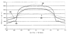
대략 90도의 꼭대기 각도를 갖는 광 변향 매크로스트럭쳐는 일반적으로 비축상 각도로(off axis angle) 입사한 광을 되돌려보내고(reject), 축 상(on-axis)에 또는 근접하여 입사한 광을 통과시킨다. 일반적으로, 시준 매크로스트럭쳐의 각도 대 루미넌스의 플롯은 90도에 근접한 각도에서 루미넌스가 감소함에 따라 0도 또는 근처에서 피크 루미넌스를 나타낸다. 루미넌스 감소의 경사는 매크로스트럭쳐 기하학의 함수이다. 매크로스트럭쳐의 표면에 거칠기를 제공하는 것에 의해 경사의 변화가 넓은 범위의 각도에 걸쳐 증가된 루미넌스를 제공하는 훌륭한 변경을 가져올 수 있음이 발견되었다. 본 발명의 바람직한 실시예에서, 광 출사 표면에 볼록 또는 오목한 매크로스트럭쳐를 포함하는 필름을 포함하는 광학 필름은, 상기 매크로스트럭쳐가 적어도 25 마이크로미터의 길이, 직경, 다른 주요한 치수를 갖고, 매크로스트럭쳐의 표면은 표면 거칠기가 없는 동일한 매크로스트럭쳐의 배열과 비교하여 적 어도 25%의 축상 광학 게인의 감소를 제공하기에 충분히 낮은 Ra 값을 제시하는 것이 바람직하다. 적어도 25%의 축상 게인의 감소는 향상된 루미넌스 특성을 갖는 광학 필름에서 나타낸 매끄러운 매크로스트럭쳐와 비교하여, 오프-각도(off-angles)에서 루미넌스의 바람직한 증가를 가져온다는 것이 발견되었다.Light deflecting macrostructures having a top angle of approximately 90 degrees generally reject the incident light at an off axis angle and allow the incident light to pass on or near the on-axis. . In general, a plot of the angle versus luminance of the collimating macrostructure shows peak luminance at or near zero degrees as the luminance decreases at an angle close to 90 degrees. The slope of the luminance reduction is a function of the macrostructure geometry. It has been found that by providing a roughness on the surface of the macrostructures, the change in the slope can bring about a good change that provides increased luminance over a wide range of angles. In a preferred embodiment of the present invention, an optical film comprising a film comprising a convex or concave macrostructure on the light exit surface, wherein the macrostructure has a length, diameter, other major dimension of at least 25 micrometers, The surface preferably presents a Ra value low enough to provide a reduction in at least 25% of axial optical gain compared to the same arrangement of macrostructures without surface roughness. It has been found that a reduction in on-axis gain of at least 25% results in a desirable increase in luminance at off-angles, compared to the smooth macrostructures shown in optical films with improved luminance characteristics.
도 1은 도 2와 관련되어 설명한 바와 같이, 광학 필름을 제작하기 위한 장치의 개략적인 다이어그램을 간략화한 것이다. 상기 장치는 물질(103)을 압출하는 압출기(100)를 포함한다. 또한, 장치는 광학층(113)에 광학 형체를 형성하는 매크로스트럭쳐를 포함하는 패터닝된 롤러(105)를 포함한다. 추가적으로, 장치는 패터닝된 롤러(105) 내로 물질(103)을 가하는 압력을 제공하는 압력 롤러(107) 및 패터닝된 롤러(105)로부터 물질(103)의 제거를 돕는 스트리핑 롤러(111)를 포함한다.FIG. 1 simplifies a schematic diagram of an apparatus for manufacturing an optical film, as described in connection with FIG. 2. The apparatus includes an extruder 100 for extruding
공정에서, 베이스 층(109)은 압력 롤러(107) 및 패터닝된 롤러(105) 사이에 압출된 물질(103)과 함께 위치된다. 실험 실시예에서, 베이스 층(109)은 배향된(oriented) 폴리머 시트이다. 더욱이, 물질(103)은 광학층(113)을 형성하고, 광학층(113)은 패터닝된 롤러(105)와 압력 롤러(107) 사이를 통과한 후 광학적 형체를 포함한다. 대안으로, 점착층은 압출기(101)에서 물질(103)과 공유 압출될 것이다. 공유압출성형(Co-extrusion)은 둘 이상의 층 이익을 제공한다. 공유 압출된 점착층은 단일층보다 높은 점착력을 생성하는 베이스 층(109) 및 광학층(113)에 최적의 점착을 제공하기 위해 선택될 수 있다. 따라서, 공유 압출된 점착 및 광학층은 입력 롤러(107) 및 패터닝된 롤러(105) 사이의 베이스 층에 힘을 작용한다. 압력 롤러(107) 및 패터닝된 롤러(105) 사이를 통과한 후, 층(113)은 롤러(111)를 따라 통과한다. 특정 실시예에서, 층(113)은 도 3의 관점에서 상세하게 기술된 실시예의 광학 구조이다. In the process, the
다른 바람직한 실시예에서, 물질(103)은 공유 압출된 구조에서 잔여층들보다 50% 더 큰 녹는점을 갖는 패터닝된 롤러(105)와 접촉하는 스킨층(skin layer)를 갖는 폴리머의 공유 압출된 층을 포함한다. 높은 유동 스킨층은 폴리머의 복제 충실성을 돕는 것으로 알려져 있다. 스킨층 외의 다른 층은 훨씬 낮은 녹는점을 갖고, 기계적으로 딱딱한 광학 필름을 가져와 디스플레이 장치의 엄격함을 견디기에 더 적합할 것이다. In another preferred embodiment, the
본 발명은 이하에서 설명하는 전형적인 배열의 액정표시장치와 함께 사용될 것이다. 액정(LC)은 전자 디스플레이에 널리 사용되고 있다. 이러한 디스플레이 시스템에서, LC 층은 편광층과 분석층(analyzer layer) 사이에 위치하고, 수직축에 대하여 층을 통해 방위각이 트위스트된 것을 나타내는 유도기(director)를 갖는다. 본석기는 배향되어 흡수축이 폴라라이저의 흡수측에 대하여 수직하다. 액정 셀을 통과하여 폴라라이저에 의해 편광된 입사된 광은 액정의 분자 방향에 의해 영향을 받는다. 상기 액정의 분자 방향은 셀을 통하는 전압의 응용에 의해 대체될 수 있다. 이 원칙을 적용하여, 환경 광을 포함하는, 외부 소스로부터 광의 전송이 제어될 수 있다. 이러한 제어를 얻기 위해 요구되는 에너지는 일반적으로 음극선관과 같은 다른 디스플레이 타입에 사용되는 조명 물질을 위해 요구되는 것보다 훨씬 적다. 따라서, LC 기술은 표준 중량, 낮은 파워 소비, 긴 동작 수명이 중요한 특징인 디지털 시계, 계산기, 휴대용 컴퓨터, 전자 게임기를 포함하나, 이에 제한되지 않 는, 많은 어플리케이션에 사용된다.The present invention will be used with a liquid crystal display of the typical arrangement described below. Liquid crystals (LC) are widely used in electronic displays. In such display systems, the LC layer is located between the polarizing layer and the analyzer layer and has a director indicating that the azimuth angle is twisted through the layer with respect to the vertical axis. The main stone is oriented so that the absorption axis is perpendicular to the absorption side of the polarizer. The incident light polarized by the polarizer through the liquid crystal cell is affected by the molecular direction of the liquid crystal. The molecular orientation of the liquid crystal can be replaced by the application of voltage through the cell. By applying this principle, the transmission of light from an external source, including ambient light, can be controlled. The energy required to obtain this control is generally much less than that required for lighting materials used in other display types such as cathode ray tubes. Accordingly, LC technology is used in many applications, including, but not limited to, digital watches, calculators, portable computers, electronic gaming machines, where standard weight, low power consumption, and long operating life are important features.
액티브-매트릭스(Active Matrix) LCD는 각 액정 픽셀을 구동하기 위한 스위칭 장치로 TFT(Thin Film Transistor)를 사용한다. 이러한 LCD는 개별 액정이 선택적으로 구동되기 때문에 크로스토크(cross talk) 없이 높은 해상도 이미지를 디스플레이할 수 있다. OMI(Optical Mode Interference) 디스플레이는 액정 디스플레이로, "일반적으로 화이트", 즉 광이 오프 상태에서 디스플레이 층을 투과한다. 투위스트된 네마틱(nematic) 액정이 사용되는 LCD의 동작 모드는 개략적으로 복굴절 모드와 광학적 회절 모드로 나뉜다. FSTN(Film-compensated Super-Twisted Nematic) LCD는 일반적으로 블랙, 즉, 전압이 가해지지 않을 때 광 투과가 오프 상태에서 제한된다. 전하는 바에 따르면, OMI 디스플레이는 빠른 응답 속도 및 넓은 동작 온도 범위를 갖는다.Active Matrix LCDs use Thin Film Transistors (TFTs) as the switching device for driving each liquid crystal pixel. Such LCDs can display high resolution images without cross talk because the individual liquid crystals are selectively driven. An Optical Mode Interference (OMI) display is a liquid crystal display that is "normally white", ie light is transmitted through the display layer in the off state. The operating mode of the LCD in which the twisted nematic liquid crystal is used is roughly divided into the birefringence mode and the optical diffraction mode. Film-compensated Super-Twisted Nematic (FSTN) LCDs are generally black, i.e. light transmission is limited in the off state when no voltage is applied. Allegedly, OMI displays have a fast response speed and a wide operating temperature range.
본 발명의 광학 필름은 필름이 백라이트 시스템에서 광 산란 필름으로 사용될 때에도 루미넌스를 출력할 수 있다. 백-릿(Back lit) LCD 디스플레이 스크린은, 휴대용 컴퓨터에서 사용되는 것과 같은, LCD 스크린에 상대적으로 가까이 위치한 상대적으로 집중된 광원(예를 들어, 형광) 또는 상대적으로 집중된 광원의 배열을 가져 광원에 따른 각 "핫 스팟(hot spot)"이 발견될 수 있다. 확산 필름이 디스플레이의 전역에서 조명의 균형을 잡도록 할 것이다. 액정표시장치는 예를 들어 액티브 매트릭스 구동 및 단순 매트릭스 구동으로부터 선택된 구동 방법과 트위스트 네마틱, 수퍼트위스트 네마틱, 강유전성 액정 및 안티-강유전성 액정 모드로부터 선택된 액정 모드의 조합을 갖는 디스플레이 장치를 포함한다. 그러나, 본 발명은 상 기 조합에 제한되지 않는다. 액정표시장치에서, 본 발명의 방향성 필름은 백라이트의 앞에 위치하는 것이 필요하다. 본 발명의 광학 필름은 디스플레이 전역에 걸쳐 액정표시장치의 밝기를 고르게 할 수 있다. 왜냐하면 필름은 모든 방향에서 우수한 가시성을 주기 위해 광을 확장하는 우수한 광 산란 특성을 갖기 때문이다. 비록 상술한 효과가 이러한 필름의 단일한 사용에 의해 얻어질 수도 있지만 복수의 필름이 조합되어 사용될 것이다. 균질화된 필름은 광을 분배하기 위해 투과 모드에서 LCD 물질의 앞에 위치되어 더욱 균질하게 만들 것이다. The optical film of the present invention can output luminance even when the film is used as a light scattering film in a backlight system. Back lit LCD display screens, such as those used in portable computers, have an arrangement of relatively concentrated light sources (eg, fluorescent) or relatively concentrated light sources located relatively close to the LCD screen, Each "hot spot" can be found. The diffuser film will balance the illumination across the display. The liquid crystal display includes, for example, a display device having a combination of a driving method selected from active matrix driving and simple matrix driving and a liquid crystal mode selected from twisted nematic, supertwist nematic, ferroelectric liquid crystal and anti-ferroelectric liquid crystal modes. However, the present invention is not limited to the above combination. In the liquid crystal display, the directional film of the present invention needs to be located in front of the backlight. The optical film of the present invention can even the brightness of the liquid crystal display device across the display. This is because the film has excellent light scattering properties that extend the light to give good visibility in all directions. Although the above-described effects may be obtained by a single use of such a film, a plurality of films will be used in combination. The homogenized film will be placed in front of the LCD material in transmission mode to distribute the light, making it more homogeneous.
본 발명은 광원 해체 장치로서 중요하게 사용된다. 많은 응용에서, 샘플에 걸쳐 분배된 광이 변하고 이것이 바람직하지 않기 때문에 특정 응용에서 문제가 될 수 있는 필라멘트 구조를 광원 자체의 출력으로부터 제거하는 것이 바람직하다. 또한, 광원 필라멘트의 오리엔테이션의 변화 또는 광원이 대체된 후의 아크는 에러를 발생시키거나 잘못 읽혀질 수 있다. 광원과 감지기(detector) 사이에 위치한 본 발명의 균질화된 필름은 필라멘트 구조의 어떤 트레이스의 광원 출력으로부터 제거될 수 있고, 따라서 광원에서 광원으로 동일한 균질화된 출력을 야기한다.The present invention is importantly used as a light source disassembly apparatus. In many applications, it is desirable to remove the filament structure from the output of the light source itself, which may be problematic in certain applications because the light distributed over the sample changes and this is undesirable. In addition, changes in the orientation of the light source filaments or the arc after the light source has been replaced can cause errors or misreads. The homogenized film of the present invention, located between the light source and the detector, can be removed from the light source output of any trace of the filament structure, resulting in the same homogenized output from the light source to the light source.
광학 필름은 바람직하게는 직접적으로 만족스러운 균질화된 광이 제공되는 단계 동안 광을 조절하기 위해 사용될 것이다. 단계 및 텔레비젼 프로덕션에서, 넓은 다양한 단계의 광은 적절한 광을 위해 필수적으로 모든 다른 효과를 얻기 위해 사용될 것이다. 이것은 많은 불편하고 비싼 다른 램프가 사용될 것을 요구한다. 램프에 걸쳐 위치하는 본 발명의 필름은 요구되는 거의 제한되지 않은 유연한 분산된 광을 줄 수 있다. 결과적으로, 움직이거나 아니거나, 어떠한 물체, 어떠한 형상도 정확하게 조명할 수 있다.The optical film will preferably be used to adjust the light during the step in which directly satisfactory homogenized light is provided. In stage and television production, a wide variety of stages of light will be used to achieve all the different effects necessary for proper light. This requires that many uncomfortable and expensive other lamps be used. The film of the present invention, placed across the lamp, can give almost unlimited flexible distributed light as required. As a result, it is possible to accurately illuminate any object, any shape, moving or not.
반사 필름은 금속 필름 등으로 구성된 반사층을 본 발명의 광학 필름의 광 출사 표면에 적용하여 형성될 수 있고, 예를 들어, 교통신호를 위한 역반사 부재로 사용될 수 있다. 차, 자전거, 사람 등에 적용된 상태로 사용될 수 있다.The reflective film can be formed by applying a reflective layer composed of a metal film or the like to the light exit surface of the optical film of the present invention, and can be used, for example, as a retroreflective member for a traffic signal. It can be used as applied to cars, bicycles, people, etc.
본 발명의 광학 필름은 또한 법 강화 지역 및 보안 시스템에서 자외선(IR) 검지기의 높은 콘트라스트를 제공하기 위해 레이저 다이오드(LD) 또는 발광 다이오드(LED)로부터 출력을 전 보안 영역에 걸쳐 균질화하기 위해 사용될 수 있다. 본 발명의 필름은 또한 은행 노트 리더기 또는 피부 처리 장치와 같은 LED 또는 LD 소스가 사용되는 장치로부터 구조를 제거하기 위해 사용될 수 있다. 이것은 높은 정확도를 가져온다. The optical film of the present invention can also be used to homogenize the output from the laser diode (LD) or light emitting diode (LED) across the entire security area to provide high contrast of ultraviolet (IR) detectors in law-enforced areas and security systems. have. The film of the present invention can also be used to remove structure from devices in which LED or LD sources are used, such as bank note readers or skin treatment devices. This brings high accuracy.
의사의 헤드피스(headpiece)에 설치된 섬유-광학적 광 어셈블리들(fiber-optic light assemblies)은, 만일 섬유-광학적 요소들 중 하나가 외과 수술 중 파손된다면, 혼란시키는 강도 변화를 외과 수술 현장에 비출 수 있다. 섬유 다발(fiber bundle)의 종단에 위치된 본 발명의 광학 필름은 나머지 섬유들로부터 오는 광을 균질화하고, 환자에게 비춰지는 광으로부터 파손된 섬유의 흔적을 제거한다. 표준 그라운드 글래스 확산기(standard ground glass diffuser)는, 작업량 손실을 유발시키는 상당한 백-스캐터(back-scatter) 때문에 이러한 사용에 있어서 효과적이지 않을 것이다. Fiber-optic light assemblies installed in the surgeon's headpiece can project disruptive intensity changes to the surgical site if one of the fiber-optic elements breaks during surgery. have. The optical film of the present invention located at the end of the fiber bundle homogenizes the light coming from the remaining fibers and removes traces of the broken fiber from the light shining on the patient. A standard ground glass diffuser will not be effective in this use because of the significant back-scatter that causes work loss.
또한, 본 발명의 광학 필름들은, 소스(source)의 아크 또는 필라멘트의 구조를 해체하고 동일하게 비추어진 시야를 산출함으로써, 마이크로스코프 아래의 샘플 을 동일하게 비추기 위해 사용될 수도 있다. 또한, 필름들은 섬유를 통해 전파되는 다양한 모드들, 예를 들어 헬리컬 모드 섬유(helical-mode fiber)로부터의 광출력을 균질화하기 위하여 사용될 수도 있다.In addition, the optical films of the present invention may be used to equally illuminate the sample under the microscope by dismantling the structure of the arc or filament of the source and yielding the same illuminated field of view. The films may also be used to homogenize light output from various modes propagating through the fiber, for example helical-mode fiber.
또한, 본 발명의 광학 필름들은 작업 및 거주 공간들을 위한 적절한 조명을 제공하는 것과 같은 중요한 건축적인 사용들도 가진다. 일반적인 상업적인 적용들에서, 비싸지 않은 투명 폴리머 확산 필름들이 방에 대하여 광을 확산시키는 것을 돕기 위해 사용된다. 이들 종래의 확산기들 중 하나를 대체하는, 본 발명의 균질기(homogenizer)는 더 균일한 광 출력을 제공하여 광이 방을 가로질러 모든 각도로 균등하고 핫 스팟(hot spot)이 없도록 확산되도록 한다.The optical films of the present invention also have important architectural uses, such as providing adequate lighting for work and living spaces. In general commercial applications, inexpensive transparent polymer diffusion films are used to help diffuse light over the room. The homogenizer of the present invention, which replaces one of these conventional diffusers, provides a more uniform light output such that the light diffuses evenly at all angles across the room and free of hot spots. .
본 발명의 광학 필름들은 또한 예술작품을 비추는 광을 확산시키기 위해 사용될 수도 있다. 투명 폴리머 필름 확산기는 가장 바람직한 방법으로 예술 작품을 묘사하기 위하여 적합하고 적절하게 크기를 가지고 방향을 가지는 개구를 제공한다.The optical films of the present invention may also be used to diffuse light that illuminates a work of art. The transparent polymer film diffuser provides an opening that is suitable and appropriately sized and oriented to depict the work of art in the most desirable manner.
더 나아가, 본 발명의 광학 필름은 디스플레이 장치와 같은 광학적 장치를 위한 부품으로서 광범위하게 사용될 수 있다. 예를 들어, 위에서 언급한 액정 디스플레이 장치의 백라이트 시스템의 광 스캐터링 판에 더하여, 장치의 뒤쪽(시청자의 반대편)에 금속 필름을 위치시키는 경우에 앞쪽(시청자 편)으로 필름을 안내하는 프론트 스캐터링 필름(front scattering film) 또는 반사 액정 디스플레이 장치 내의 금속 필름과 같은 반사 필름과 함께 라미네이트(laminate)된 광 반사판(light-reflection plate)으로서 사용될 수 있다. 본 발명의 광학 필름은, ITO 필름으로 표시되는 인듐 산화물로 이루어진 투명 전도층을 라미네이트함으로써 전극으로서 사용될 수 있다. 만일 물질이 반사 스크린, 예를 들어 프론트 프로젝션 스크린(front projection screen)을 형성하기 위하여 사용된다면, 광 반사층은 투명 폴리머 필름 확산기에 적용된다.Furthermore, the optical film of the present invention can be widely used as a component for an optical device such as a display device. For example, in addition to the light scattering plate of the backlight system of the liquid crystal display device mentioned above, the front scattering which guides the film to the front side (viewer side) when the metal film is placed on the back side (the opposite side of the viewer) of the device. It can be used as a light-reflection plate laminated with a reflective film, such as a front scattering film or a metal film in a reflective liquid crystal display device. The optical film of the present invention can be used as an electrode by laminating a transparent conductive layer made of indium oxide represented by an ITO film. If the material is used to form a reflective screen, for example a front projection screen, a light reflective layer is applied to the transparent polymer film diffuser.
광학 필름을 위한 다른 적용은 리어 프로젝션 스크린(rear projection screen)이고, 여기서 넒은 범위에 걸쳐 스크린 상으로 광원으로부터 화상을 투사하는 것이 일반적으로 요구된다. 텔레비젼에 대한 시야각은 일반적으로 수평 방향보다는 수직 방향에서 일반적으로 더 작다. 광학 필름은 시야각을 증가시키기 위하여 광을 퍼뜨리도록 작용한다.Another application for optical films is a rear projection screen, where it is generally required to project an image from a light source onto the screen over a wide range. The viewing angle for the television is generally smaller in the vertical direction than in the horizontal direction. The optical film acts to spread the light to increase the viewing angle.
본 발명의 실시예들은 향상된 광 확산 및 시준 뿐 아니라 감소된 광 흡수 경향을 가지거나, 부드러운 앵귤러 컷오프를 나타내거나, LCD 디스플레이 시스템에서 감소된 무아레 또는 뉴턴 링을 보여주는, 감소된 두께의 광학 필름을 제공할 수 있다. Embodiments of the present invention provide a reduced thickness optical film having improved light diffusion and collimation as well as reduced light absorption tendency, exhibiting smooth angular cutoff, or showing reduced moire or Newton rings in LCD display systems. can do.
본 발명은 몇몇 바람직한 실시예들을 참조하여 상세하게 설명되었지만 본 발명의 사상 및 범위 내에서 변경 및 수정이 유효할 수 있다는 것은 이해될 것이다.Although the invention has been described in detail with reference to some preferred embodiments, it will be understood that variations and modifications may be effective within the spirit and scope of the invention.
실험예Experimental Example
본 실험예에서, 1200 마이크로미터의 길이, 35 마이크로미터의 폭 및 27 마이크로미터의 높이이며, 약 90도의 꼭대기 각도를 가지는, 개별적인 일체화된 광학 요소들을 포함하는 폴리카보네이트 베이스 시트가 몇몇 광학적 변형층으로 코팅되 었다. 뉴욕 로체스터의 Eastman Kodak Company에 의해 제조된 13 인치 폭의 마이크로 복제된 폴리카보네이트 서포트(micro replicated polycarbonate support)는, 광학적 변형층이 없는 광학 요소와 대비하여 부드러운 앵귤러 컷오프를 가지는 향상된 넓은 각도 상황을 만들기 위하여 코팅되었다. In this experimental example, a polycarbonate base sheet comprising individual integrated optical elements, with a length of 1200 micrometers, a width of 35 micrometers and a height of 27 micrometers, and having a top angle of about 90 degrees, was fabricated with several optically deformable layers. Coated. The 13-inch wide micro replicated polycarbonate support, manufactured by Eastman Kodak Company in Rochester, New York, is designed to create an improved wide-angle situation with smooth angular cutoffs as compared to optical elements without optical strain layers. Coated.
마이크로 복제된 폴리카보네이트 서포트 상에 코팅되었던 1 킬로그램 디스퍼젼(dispersion)을 만들기 위하여, 비드 코팅 공정을 돕기 위한 소량의 계면활성제와 함께, 988.3 그램의 물, 11.7 그램의 포토그래픽 젤라틴이 함께 추가되었다. 이러한 총 디스퍼젼은 50℃까지 가열되었다.988.3 grams of water, 11.7 grams of photographic gelatin were added together with a small amount of surfactant to aid the bead coating process to make a 1 kilogram dispersion that had been coated onto the micro replicated polycarbonate support. This total dispersion was heated to 50 ° C.
젤라틴 및 매트(matte) 비드 디스퍼젼은 50℃에서 액화되었고(liquefied), 38.1 cm3/m2의 웨트 커버리지(wet coverage)로 마이크로 복제된 폴리카보네이트 서포트에 코팅되고, 건조되었다. 본 실험예에서 사용된 바인더는 포토그래픽 젤라틴(photographic gelatin)이지만, 본 발명은 유기 물질들, 예를 들어 폴리비닐 알콜(PolyVinyl Alcohol) 및 폴리비닐 피릴리돈(PolyVinyl Pyrrilidone), 및 무기 물질과 같은, 젤라틴 외의 바인더들을 사용할 수 있었다.Gelatin and matte bead dispersions were liquefied at 50 ° C., coated on micro replicated polycarbonate support with wet coverage of 38.1 cm 3 / m 2 , and dried. The binder used in this experimental example is photographic gelatin, but the present invention relates to organic materials, such as polyvinyl alcohol and polyvinyl pyrilidone, and inorganic materials. Binders other than gelatin could be used.
실험예Experimental Example 2-23 2-23
뉴욕 로체스터의 Eastman Kodak Company에 의해 제조된 13 인치 폭의 마이크로 복제된 폴리카보네이트 서포트(micro replicated polycarbonate support)는 향상된 넓은 각도 상황을 만들기 위하여 코팅되었다. The 13 inch wide micro replicated polycarbonate support manufactured by Eastman Kodak Company in Rochester, New York was coated to create an improved wide angle situation.
1 킬로그램의 젤라틴 디스퍼젼 및 매트 비드 조성물이 다음과 같이 준비되었다. 702그램의 증류수, 60그램의 포토그래픽 젤라틴 및 234그램으로 시작하여, 젤라틴 및 2-프로페노익산(2-Propenoic acid), 2-메틸-, 메틸 에스테르, 호모폴리머의 코폴리머의 수용액(aqueous solution)이 생성된다. 마이크로스코픽 분석은 수용성 젤라틴 미디움(aqueous gelatin medium) 내에 균일한 1.3-마이크론 매트 비드로 구성된 디스퍼젼을 보여주었다. 매트 비드 크기가 표 1에 보여지는 것처럼 증가 또는 감소함에 따라 미세한 제제 변화(minute formulation changes)가 필요하다. 추가적으로 매트 비드들의 물질 조성이 표 1에 표시된 바와 같이 변함에 따라 미세한 제제 변화(minute formulation changes)가 필요하다.One kilogram of gelatin dispersion and matte bead composition were prepared as follows. Starting with 702 grams of distilled water, 60 grams of graphical gelatin and 234 grams, an aqueous solution of copolymers of gelatin and 2-propenoic acid, 2-methyl-, methyl esters, homopolymers ) Is generated. Microscopic analysis showed a dispersion consisting of homogeneous 1.3-micron matte beads in aqueous gelatin medium. Minute formulation changes are required as the mat bead size increases or decreases as shown in Table 1. In addition, minute formulation changes are required as the material composition of the mat beads changes as shown in Table 1.
마이크로 복제된 폴리카보네이트 서포트(micro replicated polycarbonate support) 상에 코팅되었던 1 킬로그램 디스퍼젼을 만들기 위하여, 962그램의 물, 11.7그램의 포토그래픽 젤라틴 및 젤라틴 및 매트 비드들을 함유하는 26.3 그램의 디스퍼젼이 코팅 공정을 돕기 위한 소량의 계면활성제와 함께 추가되었다. 이러한 전체 디스퍼젼은 50℃까지 가열되었다.To make a 1 kilogram dispersion that was coated onto a micro replicated polycarbonate support, 26.3 grams of dispersion containing 962 grams of water, 11.7 grams of photographic gelatin and gelatin and matt beads were coated. Added with a small amount of surfactant to aid the process. This entire dispersion was heated to 50 ° C.
젤라틴 및 매트 비드 디스퍼젼은 50℃에서 액화되었고(liquefied), 38.1 cm3/m2의 웨트 커버리지(wet coverage)로 마이크로 복제된 폴리카보네이트 서포트에 코팅되고, 건조되었다. Gelatin and matt bead dispersions were liquefied at 50 ° C., coated on micro replicated polycarbonate support with a wet coverage of 38.1 cm 3 / m 2 , and dried.
이러한 넓은 각도 향상층 디스퍼젼은 다중 매트 비드 사이즈들이 사용자 조건에 따라 용이하게 형성될 수 있도록 된다. 이것은 또한 마이크로 복제된 폴리카 보네이트 서포트가 캐스트(cast)될 때 동시에 코팅되거나(1 패스) 마이크로 복제된 폴리카보네이트 서포트의 뒤에 분리되어 코팅될 수 있기 위하여(2 패스) 형상화된다.This wide angle enhancement layer dispersion allows multiple mat bead sizes to be easily formed according to user requirements. It is also shaped so that the micro replicated polycarbonate support can be coated at the same time as it is cast (one pass) or separately coated (two passes) behind the micro replicated polycarbonate support.

작은 매트 비드 및 젤라틴으로 구성된 디스퍼젼은, 비드가 없는 샘플들 및 더 큰 크기의 비드들을 가진 샘플들과 대비할 때, 마이크로 복제된 형체들의 더 균일한 커버리지를 허용하고, 더 높은 비축상 휘도(off-axis brightness)를 산출한다. 바람직한 실시예는 0.110 내지 3.6 마이크론, 바람직하게는 0.68 내지 1.3 마이크론의 크기 범위의 비드들을 포함한다. 매트 비드들이 0.68미크론보다 작아졌을 때, 광을 회절시킬 수 없는 능력(inability to diffract light) 때문에 효과는 상당히 감소되었다. 매트 비드들이 3.6 마이크론보다 커졌을 때, 비드들은 시야각의 함수로서 광학적 성능을 감소시키며, 마이크로 복제된 밸리(micro replicated valley) 내에 설치된다. 도 6 내지 10은 마이크로 복제된 형체 상의 위치 함수(function)로서 매트 비드들을 포함하는 디스퍼젼의 커버리지를 도시한다.Dispersion consisting of small matt beads and gelatin allows for more uniform coverage of micro replicated shapes and higher off-axis brightness when compared to samples without beads and samples with larger size beads. -axis brightness) Preferred embodiments include beads in the size range of 0.110 to 3.6 microns, preferably 0.68 to 1.3 microns. When the matt beads were smaller than 0.68 micron, the effect was significantly reduced due to the inability to diffract light. When the mat beads are larger than 3.6 microns, the beads decrease optical performance as a function of viewing angle and are placed in a micro replicated valley. 6-10 show coverage of a dispersion including mat beads as a position function on the micro replicated shape.
디스퍼젼 웨트 레이다운(dispersion wet laydown)은 공정 조건들과 광학적 성능 사이의 상호 작용을 맞춤 설계하기 위하여 사용될 수 있다. 본 발명의 바람직한 실시예는 16.1 내지 38.1 cm3/m2 범위의 웨트 레이다운을 포함한다. 이 공정 변수는 본 발명의 광학적 요구 조건을 기초로 한 제조 공정을 최적화하기 위하여 사용될 수 있다.Dispersion wet laydown can be used to custom design the interaction between process conditions and optical performance. Preferred embodiments of the invention include wet laydowns in the range of 16.1 to 38.1 cm 3 / m 2 . This process variable can be used to optimize the manufacturing process based on the optical requirements of the present invention.
도 11-14는 본 발명의 다양한 실시예들에 대하여 시야각의 함수로서 광학적 성능을 도시한다. 도 11은 액정 디스플레이 내의 다양한 요소들에 대한 수평기울기 각도의 함수로서 루미넌스를 도시한다. 볼륨 확산기(volume diffuser; 506)는 본 발명의 기준으로서 사용된다. 2개의 상이한 실시예들이 루미넌스 곡선(502, 504)에 의하여 나타나 진다. 곡선(502)으로 표시된 실험예 3에서, 비드 크기 및 레이다운은 더 큰 기울기 각도들에서 루미넌스 곡선의 부드러운 컷오프를 제공하기 위하여 최적화되었다. 곡선(504)에 의해 표시되는 실험예 18에서, 비드 크기 및 레이다운은 더 큰 기울기 각도들에서 루미넌스 곡선의 더 날카로운 컷오프를 제공하기 위하여 최적화되었다. 더 큰 기울기 각도들에서 본 발명 게인을 보여주기 위하여 상업적으로 이용 가능한 휘도 향상 필름(500)이 추가적인 기준(reference)으로서 도 11에 포함되었다. 11-14 illustrate optical performance as a function of viewing angle for various embodiments of the present invention. 11 shows luminance as a function of horizontal tilt angle for various elements in a liquid crystal display.
도 12는 수직 경사 각도의 함수로서 루미넌스 프로파일(profile)을 도시한다. 기울기 각도의 함수로서 루미넌스 곡선 상의 유사한 부드러운 컷오프는 수직 방향으로 얻어진다. 12 shows the luminance profile as a function of the vertical tilt angle. Similar smooth cutoffs on the luminance curve as a function of the tilt angle are obtained in the vertical direction.
도 13 및 14는 기울기 각도의 함수로서 수평 및 수직 방향 각각의 광학 게인을 도시한다. 도 11 및 12에 만들어진 것들과 유사한 관찰들이 도 13 및 14 상에서 만들어 질 수 있고, 광학 게인 프로파일의 더 부드러운 컷오프는 기울기 각도의 함수로서 수평과 수직 방향 모두에서 관찰될 수 있다.13 and 14 show optical gains in the horizontal and vertical directions, respectively, as a function of the tilt angle. Observations similar to those made in FIGS. 11 and 12 can be made on FIGS. 13 and 14, and a smoother cutoff of the optical gain profile can be observed in both the horizontal and vertical directions as a function of the tilt angle.
본 발명에서 참조된 특허들 및 다른 출원들은 참조를 위하여 본 명세서에 병합되는 것이다..Patents and other applications referenced in the present invention are hereby incorporated by reference.
도 1은 실험 실시예에 따른 광학 필름을 제작하기 위한 장치의 개략적인 다이어그램을 간략화한 것이다.1 is a simplified diagram of an apparatus for manufacturing an optical film according to an experimental embodiment.
도 2는 실험 실시예에 따른 매크로스트럭쳐의 확대된 평면도이다.2 is an enlarged plan view of a macrostructure according to an experimental embodiment.
도 3은 실험 실시예에 따른 매크로스트럭쳐의 확대된 평면도이다.3 is an enlarged plan view of a macrostructure according to an experimental embodiment.
도 4는 실험 실시예에 따른 매크로스트럭쳐의 확대된 평면도이다.4 is an enlarged plan view of a macrostructure according to an experimental embodiment.
도 5는 실험 실시예에 따른 매크로스트럭쳐의 확대된 평면도이다.5 is an enlarged plan view of a macrostructure according to an experimental embodiment.
도 6은 실험 실시예에 따른 광 변형층으로 코팅된 매크로스트럭쳐의 확대된 평면도이다.6 is an enlarged plan view of a macrostructure coated with a light modifying layer according to an experimental embodiment.
도 7은 실험 실시예에 따른 광 변형층으로 코팅된 매크로스트럭쳐의 확대된 평면도이다.7 is an enlarged plan view of a macrostructure coated with a light modifying layer according to an experimental embodiment.
도 8은 실험 실시예에 따른 광 변형층으로 코팅된 매크로스트럭쳐의 확대된 평면도이다.8 is an enlarged plan view of a macrostructure coated with a light modifying layer according to an experimental embodiment.
도 9는 실험 실시예에 따른 광 변형층으로 코팅된 매크로스트럭쳐의 확대된 평면도이다.9 is an enlarged plan view of a macrostructure coated with a light modifying layer according to an experimental embodiment.
도 10은 실험 실시예에 따른 광 변형층으로 코팅된 매크로스트럭쳐의 확대된 평면도이다.10 is an enlarged plan view of a macrostructure coated with a light modifying layer according to an experimental embodiment.
도 11은 종래의 광학 필름 및 두 실험 실시예의 수평 경사각과 루미넌스 사이의 플롯(plot)이다.FIG. 11 is a plot between the horizontal tilt angle and luminance of a conventional optical film and two experimental examples. FIG.
도 12는 종래의 광학 필름 및 두 실험 실시예의 수직 경사각과 루미넌스 사 이의 플롯이다.12 is a plot between the vertical tilt angle and luminance of a conventional optical film and two experimental examples.
도 13은 종래의 광학 필름과 두 실험 실시예의 수평 경사각과 광학 게인 사이의 플롯이다.13 is a plot between the horizontal tilt angle and optical gain of a conventional optical film and two experimental examples.
도 14는 종래의 광학 필름과 두 실험 실시예의 수직 경사각과 광학 게인 사이의 플롯이다.14 is a plot between the vertical tilt angle and optical gain of a conventional optical film and two experimental examples.
<도면부호><Drawing symbol>
101: 압출 다이(Extrusion die)101: Extrusion die
103: 폴리머 멜트(Polymer melt)103: polymer melt
105: 패터닝된 롤러(Patterned roller)105: Patterned roller
107: 백킹 롤러(Backing roller)107: backing roller
109: 캐리어 웹(Carrier web)109: carrier web
111: 스트리핑 롤러(Stripping roller)111: stripping roller
113: 광학 필름(Optical film)113: Optical film
500: 상업적으로 이용가능한 휘도 향상 필름(Commercially available brightness enhancement film)500: Commercially available brightness enhancement film
502: 발명 실시에(Invention embodiment)502: Invention embodiment
504: 발명 실시예(Invention embodimemt)504: Invention embodimemt
506: 볼륨 또는 슬랩 디퓨저(Volume or slab diffuser)506: Volume or slab diffuser
Claims (33)
Applications Claiming Priority (4)
| Application Number | Priority Date | Filing Date | Title |
|---|---|---|---|
| US83371306P | 2006-07-27 | 2006-07-27 | |
| US60/833,713 | 2006-07-27 | ||
| US11/657,946 | 2007-01-25 | ||
| US11/657,946 US20080024870A1 (en) | 2006-07-27 | 2007-01-25 | Light-redirecting film containing optical modification layer |
Publications (1)
| Publication Number | Publication Date |
|---|---|
| KR20080011139A true KR20080011139A (en) | 2008-01-31 |
Family
ID=38659662
Family Applications (1)
| Application Number | Title | Priority Date | Filing Date |
|---|---|---|---|
| KR1020070076068A KR20080011139A (en) | 2006-07-27 | 2007-07-27 | Light-redirecting film containing optical modification layer |
Country Status (6)
| Country | Link |
|---|---|
| US (1) | US20080024870A1 (en) |
| EP (1) | EP1884709A3 (en) |
| JP (1) | JP2008033328A (en) |
| KR (1) | KR20080011139A (en) |
| CN (1) | CN101221255B (en) |
| TW (1) | TWI368787B (en) |
Cited By (1)
| Publication number | Priority date | Publication date | Assignee | Title |
|---|---|---|---|---|
| KR101468683B1 (en) * | 2013-03-20 | 2014-12-04 | 이병석 | Manufaturing method for LED spangle |
Families Citing this family (13)
| Publication number | Priority date | Publication date | Assignee | Title |
|---|---|---|---|---|
| US20100302479A1 (en) * | 1996-03-21 | 2010-12-02 | Aronson Joseph T | Optical article |
| US8721123B2 (en) | 2008-01-18 | 2014-05-13 | Syncrolite, Llc | Pattern generator for a light fixture |
| US8596824B2 (en) | 2005-05-24 | 2013-12-03 | Syncrolite, L.P. | Method and apparatus for a scrollable modifier for a light fixture |
| US20060268558A1 (en) * | 2005-05-24 | 2006-11-30 | Synchrolite, L.P. | Method and apparatus for controlling diffusion and color of a light beam |
| US20080081132A1 (en) * | 2006-03-30 | 2008-04-03 | Bourdelais Robert P | Light redirecting film having surface nano-nodules |
| US8616044B2 (en) * | 2008-03-21 | 2013-12-31 | The Regents Of The University Of California | Test surfaces useful for calibration of surface profilometers |
| US8488079B2 (en) * | 2008-10-21 | 2013-07-16 | Dai Nippon Printing Co., Ltd. | Optical sheet for use as a display surface |
| TWI605276B (en) | 2009-04-15 | 2017-11-11 | 3M新設資產公司 | Optical construction and display system incorporating same |
| CN102024524B (en) * | 2009-09-11 | 2012-08-29 | 群康科技(深圳)有限公司 | Preparation method of transmitting film, and transmitting film |
| US20120200816A1 (en) | 2011-02-04 | 2012-08-09 | Guardian Industries Corp. | Electronic devices having reduced susceptibility to newton rings, and/or methods of making the same |
| US20130063493A1 (en) * | 2011-09-14 | 2013-03-14 | Htc Corporation | Devices and Methods Involving Display Interaction Using Photovoltaic Arrays |
| US10222518B2 (en) | 2015-12-07 | 2019-03-05 | Keiwa Inc. | Light diffusion sheet for overlaying, and backlight unit |
| JP6647761B2 (en) * | 2015-12-07 | 2020-02-14 | 恵和株式会社 | Top light diffusion sheet and backlight unit |
Family Cites Families (16)
| Publication number | Priority date | Publication date | Assignee | Title |
|---|---|---|---|---|
| US5919551A (en) * | 1996-04-12 | 1999-07-06 | 3M Innovative Properties Company | Variable pitch structured optical film |
| JP3431415B2 (en) * | 1996-09-20 | 2003-07-28 | 恵和株式会社 | Light diffusion sheet |
| CN2324556Y (en) * | 1998-02-13 | 1999-06-16 | 台湾光宝电子股份有限公司 | Back light plate of light conducting plate with prism structure |
| EP1975649A1 (en) * | 1998-02-18 | 2008-10-01 | Minnesota Mining And Manufacturing Company | Optical film |
| US6752505B2 (en) * | 1999-02-23 | 2004-06-22 | Solid State Opto Limited | Light redirecting films and film systems |
| AU7064400A (en) * | 1999-09-20 | 2001-04-24 | 3M Innovative Properties Company | Optical films having at least one particle-containing layer |
| UA74186C2 (en) * | 2000-05-19 | 2005-11-15 | Лусайт Інтернешнл Юк Лімітед | Illumination device with accent lighting through the rib |
| US6608722B2 (en) * | 2000-08-01 | 2003-08-19 | James Cowan | Directional diffuser |
| US6583936B1 (en) * | 2002-03-11 | 2003-06-24 | Eastman Kodak Company | Patterned roller for the micro-replication of complex lenses |
| US6721102B2 (en) * | 2002-03-11 | 2004-04-13 | Eastman Kodak Company | Surface formed complex polymer lenses for visible light diffusion |
| CN1384391A (en) * | 2002-05-27 | 2002-12-11 | 胜华科技股份有限公司 | Structure of back lighting module |
| TWI328702B (en) * | 2003-11-04 | 2010-08-11 | Hon Hai Prec Ind Co Ltd | Backlight system |
| US7106517B2 (en) * | 2003-12-31 | 2006-09-12 | General Electric Company | Display optical films |
| JP4539160B2 (en) * | 2004-04-28 | 2010-09-08 | 日立化成工業株式会社 | Optical element, optical element manufacturing method, and surface light source device |
| JP5102623B2 (en) * | 2004-11-04 | 2012-12-19 | ランバス・インターナショナル・リミテッド | Long curved wedges in optical films |
| US20080081132A1 (en) * | 2006-03-30 | 2008-04-03 | Bourdelais Robert P | Light redirecting film having surface nano-nodules |
-
2007
- 2007-01-25 US US11/657,946 patent/US20080024870A1/en not_active Abandoned
- 2007-07-25 EP EP07113142A patent/EP1884709A3/en not_active Withdrawn
- 2007-07-26 TW TW096127218A patent/TWI368787B/en not_active IP Right Cessation
- 2007-07-26 JP JP2007194267A patent/JP2008033328A/en active Pending
- 2007-07-27 KR KR1020070076068A patent/KR20080011139A/en not_active Application Discontinuation
- 2007-07-27 CN CN2007101384371A patent/CN101221255B/en not_active Expired - Fee Related
Cited By (1)
| Publication number | Priority date | Publication date | Assignee | Title |
|---|---|---|---|---|
| KR101468683B1 (en) * | 2013-03-20 | 2014-12-04 | 이병석 | Manufaturing method for LED spangle |
Also Published As
| Publication number | Publication date |
|---|---|
| TW200815855A (en) | 2008-04-01 |
| CN101221255A (en) | 2008-07-16 |
| US20080024870A1 (en) | 2008-01-31 |
| EP1884709A2 (en) | 2008-02-06 |
| JP2008033328A (en) | 2008-02-14 |
| EP1884709A3 (en) | 2011-03-09 |
| CN101221255B (en) | 2012-01-18 |
| TWI368787B (en) | 2012-07-21 |
Similar Documents
| Publication | Publication Date | Title |
|---|---|---|
| KR20080011139A (en) | Light-redirecting film containing optical modification layer | |
| KR102199264B1 (en) | Optical sheet, backlight unit, liquid crystal display and information equipment | |
| US7543974B2 (en) | Light redirecting film having variable thickness | |
| US7367705B2 (en) | Long curved wedges in an optical film | |
| TWI449942B (en) | Light redirecting film having discontinuous coating | |
| US20080081132A1 (en) | Light redirecting film having surface nano-nodules | |
| JP2008304524A (en) | Anti-abrasion multilayer lens film | |
| JP2002071965A (en) | Light guide plate, surface light source device, and reflection type liquid crystal display device | |
| WO2006002002A1 (en) | Thermoplastic optical feature with high apex sharpness | |
| JP2010020132A (en) | Abrasion resistant lens sheet | |
| JP2011227231A (en) | Optical sheet, optical sheet combined body, backlight unit and display device | |
| JP2017116930A (en) | Optical sheet for backlight unit and backlight unit | |
| WO2017104677A1 (en) | Optical sheet for backlight unit and backlight unit | |
| JP5256723B2 (en) | Light diffusion plate, optical sheet, backlight unit, and display device | |
| TW202229935A (en) | Light diffusion sheet, backlight unit, liquid crystal display device, information apparatus, and method for manufacturing light diffusion sheet | |
| JP2014086245A (en) | Light guide plate, backlight unit and display device | |
| JP2011242419A (en) | Optical sheet, metal mold, backlight unit and display device | |
| JP2008225228A (en) | Optical sheet and backlight unit and display using the same | |
| JP2007241057A (en) | Optical sheet, and light source device, and display system | |
| JP2011150078A (en) | Optical sheet, backlight unit and display apparatus | |
| JP2009069404A (en) | Optical sheet, backlight unit using same, and display device |
Legal Events
| Date | Code | Title | Description |
|---|---|---|---|
| A201 | Request for examination | ||
| E902 | Notification of reason for refusal | ||
| E601 | Decision to refuse application |